


 Loading...
AM/FM SIGNAL GENERATORS
2023 and 2024
Operating Manual
Document part no. 46892/225
Issue 9
18 May 1998

AM/FM SIGNAL GENERATOR
2023 & 2024
9 kHz - 1.2 GHz 9 kHz - 2.4 GHz
Includes information on:
Option 1: No attenuator.
Option 2: DC operation.
Option 3: High power.
Option 4: High stability frequency standard.
Option 5: Rear panel connectors.
Option 7: Fast pulse modulation.
Option 10: 1 V peak mod input.
Option 11: Fast pulse and high power.
Option 100: Internal pulse generator.
This manual applies to instruments with software issues of 4.06 and higher.
© IFR Ltd. 2007
No part of this book may be reproduced or transmitted in any form or by any means, electronic or mechanical, including photocopying, or recorded by any information storage or retrieval system, without permission in writing by IFR Ltd.
Printed in the UK
Manual part no. 46892-225U Issue 9
18 May 1998
i

About this manual
This manual explains how to use the 2023 and 2024 AM/FM Signal Generators.
Intended audience
Persons engaged on work relating to equipment who have a need for accurately generated signals in the VHF and UHF spectrum.
Structure
Chapter 1
Main features and performance data.
Chapter 2
Installation details.
Chapter 3
Operation for the experienced user.
Chapter 4
Detailed operation including first time usage.
Chapter 5
GPIB operation with keywords and sample programs.
Chapter 6
Brief technical description.
Chapter 7
Instructions for doing acceptance testing.
Annex A
Option 100 - Internal pulse generator.
Annex B
Option 7 - Fast pulse modulation.
Annex C
Option 11 - Fast pulse and high power.
Document conventions
The following conventions apply throughout this manual:
RF OUTPUT |
Titles marked on the instrument panel are shown in capital letters, |
[TRIGGER] |
Key titles are as shown on the key-caps in square brackets, and |
Disable |
Messages on the display are shown in italic letters. |
Associated publications
There is one other publication covering specific aspects of this equipment:-
• Service manual (46880-068C) covers maintenance and repair of the equipment.
ii |
46882-225U |

CONTENTS
Preface
Precautions
Chapter 1 GENERAL INFORMATION
Chapter 2 INSTALLATION
Chapter 3 PRINCIPLES OF OPERATION
Chapter 4 LOCAL OPERATION
Chapter 5 REMOTE OPERATION
Chapter 6 TECHNICAL DESCRIPTION
Chapter 7 ACCEPTANCE TESTING
Annex A OPTION 100 - INTERNAL PULSE GENERATOR
Annex B OPTION 7 - FAST PULSE MODULATION
Annex C OPTION 11 - FAST PULSE AND HIGH POWER
Index
GENERAL |
INFORMATION |
|
|
INSTALLATION |
|
|
|
PRINCIPLESOF |
OPERATION |
|
|
LOCAL |
OPERATION |
|
|
REMOTE |
OPERATION |
|
|
TECHNICAL |
DESCRIPTION |
|
|
ACCEPTANCE |
TESTING |
INDEX

Preface
Patent protection
The 2023 and 2024 Signal Generators are protected by the following patents:
EP 0322139
GB 2214012
US 4870384
EP 0125790
GB 2140232
US 4609881
iv |
46882-225U |
Precautions
These terms have specific meanings in this manual:
WARNING 
 information to prevent personal injury.
information to prevent damage to the equipment. important general information.
Hazard symbols
The meaning of hazard symbols appearing on the equipment is as follows:
Symbol Description
!General hazard
Dangerous voltage
Toxic hazard
General conditions of use
This product is designed and tested to comply with the requirements of IEC/EN61010-1 ‘Safety requirements for electrical equipment for measurement, control and laboratory use’, for Class I, portable equipment and is for use in a pollution degree 2 environment. The equipment is designed to operate from an installation category I and II supply.
Equipment should be protected from the ingress of liquids and precipitation such as rain, snow, etc. When moving the equipment from a cold to a hot environment, it is important to allow the temperature of the equipment to stabilise before it is connected to the supply to avoid condensation forming. The equipment must only be operated within the environmental conditions specified in Chapter 1 ‘Performance data’ in the Operating manual, otherwise the protection provided by the equipment may be impaired.
This product is not approved for use in hazardous atmospheres or medical applications. If the equipment is to be used in a safety-related application, e.g. avionics or military applications, the suitability of the product must be assessed and approved for use by a competent person.
WARNING 

!Electrical hazards (AC supply voltage)
This equipment conforms with IEC Safety Class I, meaning that it is provided with a protective grounding lead. To maintain this protection the supply lead must always be connected to the source of supply via a socket with a grounded contact.
Be aware that the supply filter contains capacitors that may remain charged after the equipment is disconnected from the supply. Although the stored energy is within the approved safety requirements, a slight shock may be felt if the plug pins are touched immediately after removal.
Do not remove covers, no user serviceable parts inside. See list of IFR Ltd International Service Centres at rear of manual.
Fuses
Note that the internal supply fuse is in series with the live conductor of the supply lead. If connection is made to a 2-pin unpolarized supply socket, it is possible for the fuse to become
PRECAUTIONS
transposed to the neutral conductor, in which case, parts of the equipment could remain at supply potential even after the fuse has ruptured.
WARNING 

!Fire hazard
Make sure that only fuses of the correct rating and type are used for replacement.
If an integrally fused plug is used on the supply lead, ensure that the fuse rating is commensurate with the current requirements of this equipment. See under 'Performance Data' in Chapter 1 for power requirements.
WARNING 

 Toxic hazards
Some of the components used in this equipment may include resins and other materials which give off toxic fumes if incinerated. Take appropriate precautions, therefore, in the disposal of these items.
WARNING 

 Beryllia
Beryllia (beryllium oxide) is used in the construction of some of the components in this equipment. This material, if incorrectly handled, could cause a danger to health - refer to the Maintenance part of the Service Manual for safe handling precautions.
WARNING 

 Beryllium copper
Some mechanical components within this instrument are manufactured from beryllium copper. This is an alloy with a beryllium content of approximately 5%. It represents no risk in normal use.
The material should not be machined, welded or subjected to any process where heat is involved. It must be disposed of as “special waste”.
It must NOT be disposed of by incineration.
WARNING 

!Tilt facility
When the instrument is in the tilt position, it is advisable, for stability reasons, not to stack other instruments on top of it.
 Static sensitive components
This equipment contains static sensitive components which may be damaged by handling - refer to the Maintenance part of the Service Manual for handling precautions.
vi |
46882-225U |

PRECAUTIONS
Précautions
Les termes suivants ont, dans ce manuel, des significations particulières:
WARNING  contient des informations pour éviter toute blessure au personnel. contient des informations pour éviter les dommages aux équipements.
contient d'importantes informations d'ordre général.
Symboles Signalant Un Risque
La signification des symboles liés à cet équipement est la suivante:
Symbole |
Nature du risque |
!Risques généraux
Tension dangereuse
Danger produits toxiques
Conditions générales d’utilisation
Ce produit a été conçu et testé pour être conforme aux exigences des normes CEI/EN61010-1 “Règles de sécurité pour appareils électriques de mesurage, de régulation et de laboratoire”, pour des équipements Classe I, portables et pour une utilisation dans un environnement de pollution de niveau 2. Cet équipement est conçu pour fonctionner à partir d’une alimentation de catégorie I et II.
Cet équipement doit être protégé de l’introduction de liquides ainsi que des précipitations d’eau, de neige, etc... Lorsqu’on transporte cet équipement d’un environnement chaud vers un environnement froid, il est important de laisser l’équipement se stabiliser en température avant de le connecter à une alimentation afin d’éviter toute formation de condensation. L'appareil doit être utilisé uniquement dans le cadre des conditions d'environnement spécifiées au chapitre 1 "Performance data" du manuel d'utilisation, toute autre utilisation peut endommager les systèmes de protection.
Ce produit n’est pas garanti pour fonctionner dans des atmosphères dangereuses ou pour un usage médical. Si l'équipement doit être utilisé pour des applications en relation avec la sécurité, par exemple des applications militaires ou aéronautiques, la compatibilité du produit doit être établie et approuvée par une personne compétente.
WARNING 

!Sécurité électrique (tension d’alimentation alternative)
Cet appareil est protégé conformément à la norme CEI de sécurité Classe 1, c’est-à-dire que sa prise secteur comporte un fil de protection à la terre. Pour maintenir cette protection, le câble d’alimentation doit toujours être branché à la source d’alimentation par l’intermédiaire d’une prise comportant une borne de terre.
Notez que les filtres d’alimentation contiennent des condensateurs qui peuvent encore être chargés lorsque l’appareil est débranché. Bien que l’énergie contenue soit conforme aux exigences de sécurité, il est possible de ressentir un léger choc si l’on touche les bornes sitôt après débranchement.
Ne pas enlever les capots, aucune pièce réparable ne se trouve à l'intérieur. Contacter un des Centres de Maintenance Internationaux de IFR Ltd dans la liste jointe à la fin du manuel.
46882-225U |
vii |
PRECAUTIONS
Fusibles
Notez que le fusible d’alimentation interne est en série avec la phase du câble d’alimentation. Si la prise d’alimentation comporte deux bornes non polarisées, il est possible de connecter le fusible au neutre. Dans ce cas, certaines parties de l’appareil peuvent rester à un certain potentiel même après coupure du fusible.
WARNING 

!Risque lie au feu
Lors du remplacement des fusibles vérifiez l'exactitude de leur type et de leur valeur.
Si le cable d'alimentation comporte une prise avec fusible intégré, assurez vous que sa valeur est compatible avec les besoins en courant de l'appareil. Pour la consommation, reportez-vous au chapitre 1 "Spécifications".
WARNING 

 Danger produits toxiques
Certains composants utilisés dans cet appareil peuvent contenir des résines et d'autres matières qui dégagent des fumées toxiques lors de leur incinération. Les précautions d'usages doivent donc être prises lorsqu'on se débarrasse de ce type de composant.
WARNING 

 Le Beryllia
Le Beryllia (oxyde de Beryllium) entre dans la composition de certains composants de cet appareil. Cette matière peut représenter un danger pour la santé s'il elle n'est pas manipulée de façon correcte - se référer à la partie "Maintenance" du "Manuel de Maintenance" pour les précautions de manipulation.
WARNING 

Bronze au béryllium
Dans cet équipement,certaines pièces mécaniques sont à base de bronze au béryllium. Il s'agit d'un alliage dans lequel le pourcentage de béryllium ne dépasse pas 5%. Il ne présente aucun danger en utilisation normale.
Toutefois, cet alliage ne doit pas être travaillé, soudé ou soumis à un processus qui implique l'utilisation d'une source de chaleur.
En cas de destruction, il sera entreposé dans un container spécial. IL ne devra pas être détruit par incinération.
WARNING 

!Position inclinée
Lorsque l'appareil est dans une position inclinée, il est recommandé, pour des raisons des stabilité, de ne pas y empiler d'autres appareils.
viii |
46882-225U |
PRECAUTIONS
Vorsichtsmaßnahmen
Diese Hinweise haben eine bestimmte Bedeutung in diesem Handbuch:
WARNING  dienen zur Vermeidung von Verletzungsrisiken.
 dienen dem Schutz der Geräte.
enthalten wichtige Informationen.
Gefahrensymbole
Die Gefahrensymbole auf den Geräten sind wie folgt:
Symbol Gefahrenart
!Allgemeine Gefahr
Gefährliche Spannung
Warnung vor giftigen Substanzen
Allgemeine Hinweise zur Verwendung
Dieses Produkt wurde entsprechend den Anforderungen von IEC/EN61010-1 “Sicherheitsanforderungen für elektrische Ausrüstung für Meßaufgaben, Steuerung und Laborbedarf”, Klasse I, transportabel zur Verwendung in einer Grad 2 verunreinigten Umgebung, entwickelt und getestet. Dieses Gerät ist für Netzversorgung Klasse I und II zugelassen.
Das Gerät sollte vor dem Eindringen von Flüssigkeiten sowie vor Regen, Schnee etc. geschützt werden. Bei Standortänderung von kalter in wärmere Umgebung sollte das Gerät wegen der Kondensation erst nach Anpassung an die wärmere Umgebung mit dem Netz verbunden werden. Das Gerät darf nur in Umgebungsbedingungen wie in Kapitel 1 "Leistungsdaten (Performance data)" der Bedienungsanleitung beschrieben, betrieben werden; ansonsten wird der vom Gerät vorgesehene Schutz des Anwenders beeinträchtigt.
Dieses Produkt ist nicht für den Einsatz in gefährlicher Umgebung (z.B. Ex-Bereich) und für medizinische Anwendungen geprüft. Sollte das Gerät für den Einsatz in sicherheitsrelevanten Anwendungen wie z.B. im Flugverkehr oder bei militaerischen Anwendungen vorgesehen sein, so ist dieser von einer für diesen Bereich zuständigen Person zu beurteilen und genehmigen.
WARNING 

!Elektrische Schläge (Wechselspannungsversorgung)
Das Gerät entspricht IEC Sicherheitsklasse 1 mit einem Schutzleiter nach Erde. Das Netzkabel muß stets an eine Steckdose mit Erdkontakt angeschlossen werden.
Filterkondensatoren in der internen Spannungsversorgung können auch nach Unterbrechung der Spannungszuführung noch geladen sein. Obwohl die darin gespeicherte Energie innerhalb der Sicherheitsmargen liegt, kann ein leichter Spannungsschlag bei Berührung kurz nach der Unterbrechung erfolgen.
Entfernen Sie keine Gehäuseabdeckungen, es befinden sich keine austauschbaren Teile im Gerät. Eine Liste der IFR Servicestellen finden Sie auf der Rückseite des Handbuches.
46882-225U |
ix |
PRECAUTIONS
Sicherungen
Die interne Sicherung in der Spannungszuführung ist in Reihe mit der spannungsführenden Zuleitung geschaltet. Bei Verbindung mit einer zweiadrigen, nicht gepolten Steckdose kann die Sicherung in der Masseleitung liegen, so daß auch bei geschmolzener Sicherung Geräteteile immer noch auf Spannungspotential sind.
WARNING 

!Feuergefahr
Es dürfen nur Ersatzsicherungen vom gleichen Typ mit den korrekten Spezifikationen entsprechend der Stromaufnahme des Gerätes verwendet werden. Siehe hierzu die Leistungsdaten (Performance Data) in Kapitel 1.
WARNING 

 Warnung vor giftigen Substanzen
In einigen Bauelementen dieses Geräts können Epoxyharze oder andere Materialien enthalten sein, die im Brandfall giftige Gase erzeugen. Bei der Entsorgung müssen deshalb entsprechende Vorsichtsmaßnahmen getroffen werden.
WARNING 

 Beryllium Oxid
Beryllium Oxid wird in einigen Bauelementen verwendet.
Bei inkorrekter Handhabung kann dieses Material Gesundheitsschäden verursachen. Siehe hierzu die Hinweise zur Handhabung im Service-Handbuch.
WARNING 

 Beryllium Kupfer
In diesem Gerät sind einige mechanische Komponenten aus Berylium Kupfer gefertigt. Dies ist eine Verbindung welche aus einem Berylliumanteil von ca. 5 % besteht. Bei normaler Verwendung besteht kein Gesundheitsrisiko.
Das Metall darf nicht bearbeitet, geschweißt oder sonstiger Wärmebehandlung ausgesetzt werden. Es muß als Sondermüll entsorgt werden.
Es darf nicht durch Verbrennung entsorgt werden.
WARNING 

!Schrägstellung
Bei Schrägstellung des Geräts sollten aus Stabilitätsgründen keine anderen Geräte darauf gestellt werden.
x |
46882-225U |
PRECAUTIONS
Precauzioni
Questi termini vengono utilizzati in questo manuale con significati specifici:
WARNING  riportano informazioni atte ad evitare possibili pericoli alla persona.
 riportano informazioni per evitare possibili pericoli all'apparecchiatura. riportano importanti informazioni di carattere generale.
Simboli di pericolo
Significato dei simboli di pericolo utilizzati nell'apparato:
Simbolo |
Tipo di pericolo |
!Pericolo generico
Tensione pericolosa
Pericolo sostanze tossiche
Condizioni generali d’uso
Questo prodotto è stato progettato e collaudato per rispondere ai requisiti della direttiva IEC/EN61010-1 ‘Safety requirements for electrical equipment for measurement, control and laboratory use’ per apparati di classe I, trasportabili e per l’uso in un ambiente inquinato di grado 2. L’apparato è stato progettato per essere alimentato da un alimentatore di categoria I e II.
Lo strumento deve essere protetto dal possibile ingresso di liquidi quali, ad es., acqua, pioggia, neve, ecc. Qualora lo strumento venga portato da un ambiente freddo ad uno caldo, è importante lasciare che la temperatura all’interno dello strumento si stabilizzi prima di alimentarlo per evitare formazione di condense. Lo strumento deve essere utilizzato esclusivamente nelle condizioni ambientali descritte nel capitolo 1 ‘Performance data’ del manuale operativo, in caso contrario le protezioni previste nello strumento potrebbero risultare non sufficienti.
Questo prodotto non è stato approvato per essere usato in ambienti pericolosi o applicazioni medicali. Se lo strumento deve essere usato per applicazioni particolari collegate alla sicurezza (per esempio applicazioni militari o avioniche), occorre che una persona o un istituto competente ne certifichi l'uso.
WARNING 

!Pericoli da elettricità (alimentazione c.a.)
Quest ’apparato è provvisto del collegamento di protezione di terra e rispetta le norme di sicurezza IEC, classe 1. Per mantenere questa protezione è necessario che il cavo, la spina e la presa d’alimentazione siano tutti provvisti di terra.
Il circuito d’alimentazione contiene dei filtri i cui condensatori possono restare carichi anche dopo aver rimosso l’alimentazione. Sebbene l’energia immagazzinata è entro i limiti di sicurezza, purtuttavia una leggera scossa può essere avvertita toccando i capi della spina subito dopo averla rimossa.
Non rimuovere i coperchi, utilizzare solo parti di scorta originali. Vedi elenco internazionale dei Centri di Assistenza in fondo al manuale.
46882-225U |
xi |
PRECAUTIONS
Fusibili
Notare che un fusibile è posto sul filo caldo del cavo di alimentazione. Qualora l’alimentazione avvenga tramite due poli non polarizzati, è possibile che il fusibile vada a protezione del neutro per cui anche in caso di una sua rottura, l’apparato potrebbe restare sotto tensione.
WARNING 

!Pericolo d'incendio
Assicurarsi che, in caso di sostituzione, vengano utilizzati solo fusibili della portata e del tipo prescritti.
Se viene usata una spina con fusibili, assicurarsi che questi siano di portata adeguata ai requisiti di alimentazione richiesti dallo strumento. Tali requisiti sono riportati nel cap. 1 "Performance data".
WARNING 

 Pericolo sostanze tossiche
Alcuni dei componenti usati in questo strumento possono contenere resine o altri materiali che, se bruciati, possono emettere fumi tossici. Prendere quindi le opportune precauzioni nell'uso di tali parti.
WARNING 

 Berillio
Berillio (ossido di berillio) è utilizzato nella costruzione di alcuni componenti di quest'apparato.
Questo materiale, se maneggiato non correttamente, può causare danni alla salute. Far riferimento ai capitoli di manutenzione del Manuale di Servizio per le precauzioni richieste.
WARNING 

Rame berillio
Alcuni componenti meccanici in questo strumento sono realizzati in rame berillio. Si tratta di una lega con contenuto di berillio di circa il 5%, che non presenta alcun rischio in usi normali.
Questo materiale non deve essere lavorato, saldato o subire qualsiasi processo che coinvolge alte temperature.
Deve essere eliminato come "rifiuto speciale". Non deve essere eliminato tramite "inceneritore".
WARNING 

!Posizionamento inclinato
Quando lo strumento è in posizione inclinata è raccomandato, per motivi di stabilità, non sovrapporre altri strumenti.
xii |
46882-225U |
PRECAUTIONS
Precauciones
Estos términos tienen significados específicos en este manual:
WARNING  contienen información referente a prevención de daños personales. contienen información referente a prevención de daños en equipos.
contienen información general importante.
Símbolos de peligro
Los significados de los símbolos de peligro que aparecen en los equipos son los siguientes:
Símbolo |
Naturaleza del peligro |
!Peligro general
Voltaje peligroso
Aviso de toxicidad
Condiciones generales de uso
Este producto ha sido diseñado y probado para cumplir los requerimientos de la normativa IEC/EN61010-1 “Requerimientos de la normativa para equipos eléctricos de medida, control y uso en laboratorio”, para equipos clase I, portátiles y para uso en un ambiente con un grado de contaminación 2. El equipo ha sido diseñado para funcionar sobre una instalación de alimentación de categorías I y II.
Debe protegerse el equipo de la entrada de líquidos y precipitaciones como nieve, lluvia, etc. Cuando se traslada el equipo de entorno frío a un entorno caliente, es importante aguardar la estabilización el equipo para evitar la condensación. Sólo debe utilizarse el aparato en las condiciones ambientales especificadas en el capítulo 1 “Especificaciones” o “Performance data” del Manual de Instrucciones/Manual de Operación, en caso contrario la propia protección del equipo puede resultar dañada.
Este producto no ha sido aprobado para su utilización en entornos peligrosos o en aplicaciones médicas. Si se va a utilizar el equipo en una aplicación con implicaciones en cuanto a seguridad, como por ejemplo aplicaciones de aviónica o militares, es preciso que un experto competente en materia de seguridad apruebe su uso.
WARNING 

!Nivel peligroso de electricidad (tensión de red)
Este equipo cumple las normas IEC Seguridad Clase 1, lo que significa que va provisto de un cable de protección de masa. Para mantener esta protección, el cable de alimentación de red debe de conectarse siempre a una clavija con terminal de masa.
Tenga en cuenta que el filtro de red contiene condensadores que pueden almacenar carga una vez desconectado el equipo. Aunque la energía almacenada está dentro de los requisitos de seguridad, pudiera sentirse una ligera descarga al tocar la clavija de alimentación inmediatamente después de su desconexión de red.
No quitar las tapas, en el interior no existen piezas reemplazables por el usuario. Vea la lista de Centros de Servicios Internacionales en la parte trasera del manual.
46882-225U |
xiii |
PRECAUTIONS
Fusibles
Se hace notar que el fusible de alimentación interno está enserie con el activo del cable de alimentación a red. Si la clavija de alimentación de red cuenta con sólo dos terminales sin polaridad, el fusible puede pasar a estar en serie con el neutro, en cuyo caso existen partes del equipo que permanecerían a tensión de red incluso después de que el fusible haya fundido.
WARNING 

!Peligro de incendio
Asegúrese de utilizar sólo fusibles del tipo y valores especificados como recuesto.
Si se utiliza una clavija con fusible incorporado, asegúrese de que los valores del fusible corresponden a los requeridos por el equipo. Ver sección de especificaciones del capítulo 1 para comprobar los requisitos de alimentación.
WARNING 

 Aviso de toxicidad
Alguno de los componentes utilizados en este equipo pudieran incluir resinas u otro tipo de materiales que al arder produjeran sustancias tóxicas, Por tanto, tome las debidas precauciones en la manipulación de esas piezas.
WARNING 

 Berilio
Berilio (óxido de berilio) Este material es utilizado en la fabricación de alguno de los componentes de este equipo.
Si se manipulase incorrectamente podria causar daños a la salud - En la sección de mantenimiento y reparación encontrará normas de manejo de seguridad.
WARNING 

Berilio-cobre
Algunos componentes mecánicos contenidos en este instrumento incorporan berilio-cobre en su proceso de fabricación. Se trata de una aleación con un contenido aproximado de berilio del 5%, lo que no representa ningún riesgo durante su uso normal.
El material no debe ser manipulado, soldado, ni sometido a ningún proceso que implique la aplicación de calor.
Para su eliminación debe tratarse como un "residuo especial". El material NO DEBE eliminarse mediante incineración.
WARNING 

!Tener en cuenta con el equipo inclinado
Si utiliza el equipo en posición inclinada, se recomienda, por razones de estabilidad, no apilar otros equipos encima de él.
xiv |
46882-225U |

Chapter 1
GENERAL INFORMATION
Contents
Introduction.................................................................................................................................... |
1-2 |
Main features.................................................................................................................................. |
1-2 |
Operation................................................................................................................................. |
1-2 |
Display .................................................................................................................................... |
1-2 |
Frequency selection................................................................................................................. |
1-2 |
Output ..................................................................................................................................... |
1-2 |
Calibration............................................................................................................................... |
1-3 |
Modulation.............................................................................................................................. |
1-3 |
Incrementing ........................................................................................................................... |
1-3 |
Frequency sweep..................................................................................................................... |
1-3 |
Memory................................................................................................................................... |
1-3 |
Programming........................................................................................................................... |
1-4 |
Calibration data ....................................................................................................................... |
1-4 |
Performance data............................................................................................................................ |
1-5 |
Versions, options and accessories .................................................................................................. |
1-9 |
GENERAL INFORMATION
46882-225U |
1-1 |

GENERAL INFORMATION
Introduction
The 2023 and 2024 are portable and lightweight synthesized signal generators covering the frequency range 9 kHz to 1.2 GHz (2023) and 9 kHz to 2.4 GHz (2024). A dot matrix display with a comprehensive set of utility menus allow flexibility of operation and ease of use. The RF output can be amplitude, frequency, phase or pulse modulated. An internal programmable AF source is capable of generating simultaneous two-tone modulation.
All parameters can be entered from a front panel keyboard and a rotary control can be used to adjust most settings. Microprocessor control ensures that the instruments are flexible and easy to use and allows programming by either the General Purpose Interface Bus (GPIB) or by RS-232. The GPIB is designed to IEEE Standard 488.2. The interfaces allow remote control of all functions except the supply switch, and allow the instruments to be used either manually or as part of a fully automated test system.
Main features
Operation
Selection of parameters on the screen may involve one or more of the numeric, hard or menu selection keys or the rotary control knob. Parameters may be set to specific values by numeric key entry, while values may be varied in steps of any size using the DOWN/UP keys or altered by moving the control knob, set to a particular sensitivity.
Display
The display is a dot matrix liquid crystal panel, with backlighting. Display contrast may be varied to accommodate differing lighting conditions and the setting saved in memory. A graphical display test is available to the user.
Frequency selection
Carrier frequency is either selected directly via the keyboard or remotely via the interfaces. Frequency resolution is 1 Hz across the band. A series of carrier frequencies can be stored in nonvolatile memory for recall when required.
Output
RF output up to +13 dBm can be set by direct keyboard entry with a resolution of 0.1 dB over the entire range. For instruments fitted with the high power option, RF output is increased to
+25 dBm. A carrier ON/OFF key is provided to completely disable the output.
A choice of level units is available to the user and provision is made for the conversion of units (for example, dBm to μV) by a simple keypress.
An electronic trip protects the generator output against reverse power of up to 50 W. This prevents damage to output circuits when RF or DC power is accidentally applied to the RF OUTPUT connector.
To facilitate testing of receiver squelch systems, an attenuator hold function allows control of the RF output without introducing RF level drop-outs from the step attenuator.
The RF output level can be offset by up to ±5.0 dB to compensate for cable or switching losses, or standardize a group of instruments.
Maximum RF output level can be set so as to protect sensitive devices connected to the RF OUTPUT socket.
1-2 |
46882-225U |

Spectral purity
With an SSB phase noise performance of typically -121 dBc/Hz at 20 kHz offset from a 1 GHz carrier, these instruments can be used for both in-channel and adjacent channel receiver measurements. Harmonically related signals and non-harmonics are typically better than -25 dBc and -60 dBc respectively.
Calibration
This instrument has a recommended two year calibration interval after which it should be returned for recalibration (for addresses refer to 'Addresses' section at end of manual).
Modulation
Comprehensive amplitude, frequency and phase modulations are available. Pulse modulation can be applied to the carrier from an external pulse source. The instrument also accepts one or two logic level inputs to produce a 2-level or 4-level FSK modulated output. An internal modulation oscillator is provided, having a frequency range of 0.01 Hz to 20 kHz. The oscillator is capable of generating one or two modulation tones simultaneously in one modulation channel. An independent BNC input on the front panel allows external modulation signals to be combined with the internal signal(s). These sources can be combined to give a number of modulation modes. The pulse modulation can be used in combination with the other forms of modulation.
The frequency modulation range provides a 1 dB bandwidth of typically 100 kHz and provides FM deviation up to a maximum of 100 kHz. AC or DC coupled FM can be selected. Phase modulation is also available with a 9 kHz bandwidth up to a maximum of 10 radians.
Amplitude modulation with a 1 dB bandwidth of typically 30 kHz and with modulation depths of up to 99.9% is available with a resolution of 0.1%. Pulse modulation is available as standard with typical rise and fall times of less than 10 μs and 40 dB on/off ratio.
The external input voltage required for 100% modulation is 1 V RMS or, optionally, 1 V peak. To accommodate other signal levels, Automatic Level Control (ALC) can be selected which provides correctly calibrated modulation for inputs between 0.75 and 1.25 V RMS.
A MOD ON/OFF key simplifies the testing of signal to noise ratio.
An optional fast pulse modulator improves the rise/fall times to typically 10 ns.
Incrementing
All major parameters can be incremented or decremented in step sizes entered via keyboard entry or remotely. If no step size is entered for a parameter, the steps are preset to 1 kHz for carrier frequency, 1 kHz for modulation oscillator, 1 kHz for FM deviation, 0.1% for AM depth, 0.01 rad for ΦM and 1 dB for output level.
In addition, the rotary control knob can be used to vary the parameter with the sensitivity of the knob being changed by means of the ×10 and ÷10 keys.
Frequency sweep
The sweep capability of the instrument allows comprehensive testing of systems. Sweeps may be logarithmic or linear. Four parameters are used to specify sweep; start, stop, step size and time per step and a percentage increment in the case of logarithmic sweep, all of which may be specified by the user. The sweep can be paused at any time. During the sweep the RF level can be altered using the rotary control. Sweep triggering can be single shot or continuous and can be initiated directly or on the detection of a trigger. The triggering signal may either be programmed or from a TTL signal applied to the rear panel TRIGGER input.
Memory
The instrument provides both non-volatile and volatile memory for storing instrument settings. The non-volatile memory provides 100 instrument settings and 100 settings of carrier frequency only. The volatile memory (RAM) also provides 100 instrument settings. Any one of the nonvolatile instrument settings can be selected as the power-up setting for the instrument.
46882-225U |
1-3 |
GENERAL INFORMATION

GENERAL INFORMATION
Memory cloning
The stored settings in one instrument can be easily transferred (without the use of a controller) to another instrument using the RS-232 interface, or to several other instruments using the GPIB interface.
Memory sequencing
A software facility allows sequences of stored instrument settings to be defined. The incrementing facilities can then be used to cycle through the settings in manually operated test systems or be operated via an external trigger.
Memory protection
To prevent accidental change of the contents of the stored settings, individual memories or ranges of memories can be write-protected.
Programming
A GPIB interface is fitted so that all functions are controllable via the interface bus which is designed to the IEEE Standard 488.2. The instrument can function both as talker and listener. The instrument also has an RS-232 interface which uses the common GPIB command set. The interfaces enable the instrument to be remotely controlled as well as being used to transfer settings (cloning) from one instrument to another.
Calibration data
All alignment data is digitally derived. Realignment can be undertaken, without removing covers, by protected front panel functions or via the GPIB interface.
1-4 |
46882-225U |

Performance data
Carrier frequency |
|
|
Range: |
9 kHz to 1.2 GHz (2023). |
|
|
9 kHz to 2.4 GHz (2024). |
|
Resolution: |
1 Hz. |
|
Accuracy: |
Equal to the frequency standard accuracy. |
|
RF output |
|
|
Range: |
-140 dBm to +13 dBm. |
|
|
When AM is selected the maximum RF output level decreases linearly with increasing |
|
|
AM depth to +7 dBm at 99.9% depth. |
|
Resolution: |
0.1 dB. |
|
Accuracy: |
For output levels above -127 dBm and over a temperature range of 17 to 27°C: |
|
|
±0.8 dB to 1.2 GHz; |
|
|
±1.6 dB to 2.4 GHz. |
|
|
Temperature coefficient <±0.02 dB/°C to 1.2 GHz, and <±0.04 dB/°C to 2.4 GHz. |
|
Attenuator hold: |
Selection of Attenuator Hold provides for uncalibrated level reduction of at least 10 dB |
|
|
without the mechanical attenuator operating. |
|
RF output connector: |
50 Ω, type-N connector to MIL 390123D. |
|
VSWR: |
For output levels less than -5 dBm output VSWR is less than 1.3:1 for carrier frequencies |
|
|
up to 1.2 GHz and less than 1.5:1 for carrier frequencies up to 2.4 GHz. |
|
Output protection: |
Protected against the application of reverse power to the output connector for levels up |
|
|
to 50 W from 50 Ω or 25 W from a source VSWR of 5:1. Protection circuit can be reset |
|
|
from the front panel or via the GPIB/RS-232 interfaces. |
|
75 Ω calibration: |
The output level can be entered as the value after a 50/75 Ω external adapter. |
|
Spectral purity |
|
|
Harmonics: |
Typically better than -30 dBc for RF levels up to +7 dBm. |
|
|
Typically better than -25 dBc for RF levels up to +13 dBm. |
|
Non-harmonics: |
Better than -70 dBc for carrier frequencies up to 1 GHz. |
|
|
Better than -64 dBc for carrier frequencies above 1 GHz. |
|
|
Better than -60 dBc for carrier frequencies above 2 GHz. |
|
Residual FM (FM off): |
Less than 4.5 Hz RMS in a 300 Hz to 3.4 kHz unweighted bandwidth at a carrier |
|
|
frequency of 1 GHz. |
|
|
Residual FM (typical) |
|
|
<1 Hz at |
249 MHz |
|
<2 Hz at |
501 MHz |
|
<3 Hz at |
1001 MHz |
|
<6 Hz at |
2001 MHz |
SSB phase noise: |
Better than -124 dBc/Hz at 20 kHz offset from a 470 MHz carrier. |
|
|
Typically -121 dBc/Hz at 20 kHz offset from a 1 GHz carrier. |
|
RF leakage:
Modulation
Frequency modulation
Less than 0.5 μV at the carrier frequency into a two-turn 25 mm diameter loop 25 mm from the surface of the signal generator.
FM, AM or phase modulation can be applied to the carrier from an internal or external modulation source. The internal modulation source is capable of generating two simultaneous signals into any one of the modulation channels. Internal and external modulation can be simultaneously enabled to produce combined amplitude and frequency (or phase) modulation. Pulse modulation can be applied to the carrier from an external pulse source. The pulse modulation can be used in combination with the other forms of modulation. 2 level or 4 level FSK modulation can be applied to the carrier using data from an external source.
Deviation range: |
0 to 100 kHz. |
|
Resolution: |
3 digits or 1 Hz. |
|
Bandwidth (1 dB): |
DC to 100 kHz (DC coupled), |
|
|
10 |
Hz to 100 kHz (AC coupled), |
|
20 |
Hz to 100 kHz (AC coupled with ALC). |
Accuracy: |
±5% at 1 kHz modulation rate. |
|
Carrier frequency |
Less than 1% of the set frequency deviation. |
|
46882-225U 1-5
GENERAL INFORMATION
GENERAL INFORMATION
offset (DC coupled): Distortion:
Group delay:
FSK
Modes:
Data source:
Frequency shift:
Accuracy:
Timing jitter:
Filter:
Phase modulation
Range:
Resolution:
Bandwidth (3 dB):
Accuracy:
Distortion:
Amplitude modulation (for carrier frequencies <500 MHz, usable to
1.5GHz)
Range: Bandwidth (1 dB):
Resolution:
Accuracy:
Distortion:
ΦM on AM:
Pulse modulation (for fast pulse see Options 7 or 11 when fitted)
Carrier frequency range: RF level range:
RF level accuracy:
Input:
On-off ratio:
Rise and fall time:
Overshoot:
Modulation oscillator
Frequency range:
Resolution:
Distortion:
Sine wave frequency response:
Less than 1% at 1 kHz rate for deviations up to 100 kHz. Typically 0.3% at 1 kHz rate for deviations up to 10 kHz.
Less than 5 μs to 100 kHz.
2 level or 4 level FSK.
External data connected to 2FSK connector (2 level) or 2FSK and 4FSK connectors (4 level).
Settable up to ±100 kHz. As FM deviation accuracy.
±3.2 μs
8th order Bessel, −3 dB at 20 kHz.
0 to 10 radians.
3 digits or 0.01 radians.
100 Hz to 10 kHz.
±5% at 1 kHz modulation rate.
Less than 3% at 10 radians at 1 kHz.
Typically 0.5% for deviations up to 1 radian at 1 kHz.
0 to 99.9%.
DC to 30 kHz (DC coupled), 10 Hz to 30 kHz (AC coupled),
20 Hz to 30 kHz (AC coupled with ALC). 0.1%.
±5% of set depth at 1 kHz rate at +17°C to 27°C ambient temperature. Temperature coefficient <0.02% per °C.
Less than 2.5% at 1 kHz rate for modulation depths up to 80%. Less than 1.5% at 1 kHz rate for modulation depths up to 30%.
Typically 0.1 radians at 30% depth at 470 MHz.
32 MHz to 2.4 GHz, usable to 10 MHz.
Maximum guaranteed output is reduced to +8 dBm (+20 dBm or +14 dBm with high power option) when pulse modulation is selected.
Maximum additional uncertainty is ±0.5 dB.
Rear panel BNC connector with an input impedance of 10 kΩ nominal. A logical '1' (5 V) turns the carrier on, a logical '0' (0 V) turns the carrier off. Maximum safe input is ±15 V.
Better than 40 dB,
better than 45 dB below 1.2 GHz. Less than 10 μs.
Less than 1 dB.
The internal modulation oscillator is capable of generating one or two modulation tones simultaneously in one modulation channel.
0.01Hz to 20 kHz.
0.01Hz to 100 Hz,
0.1Hz to 1 kHz,
1 Hz to 20 kHz.
Less than 0.1% at 1 kHz. Typically 1 dB DC to 20 kHz.
1-6 |
46882-225U |

Waveforms:
Output:
External modulation input
Input level:
Input impedance:
Modulation ALC:
Sweep mode
Frequency standard
Internal standard:
Aging rate:
Temperature stability:
External standard:
Calibration interval
Remote control
GPIB:
Capabilities:
RS-232:
Connector:
Baud rate:
Handshake:
Electrical:
Electromagnetic compatibility
Safety
Rated range of use (over which full specification is met)
Conditions of storage and transport
Power requirements
Dimensions and weight
Sine (to 20 kHz),
triangle or square wave (to 3 kHz). Square wave jitter <6.4 μs on any edge.
The modulation oscillator signal is available on a front panel BNC connector at a nominal level of 2 V RMS EMF from a 600 Ω source impedance.
A front panel external modulation input is provided.
1 V RMS (1.414 V peak) sine wave for set deviation. Input sensitivity may be optionally specified for 1 V peak (Option 10). Maximum safe input is ±15 V.
100 kΩ nominal.
Levels the applied external modulation over the range 0.75 to 1.25 V RMS. High and low indicators in display indicate when the input is outside levelling range.
A carrier frequency sweep mode is provided. The sweep is defined by entry of the start, stop and frequency step size. The sweep step size may be specified linearly or logarithmically. The step time can be set from 20 ms to 10 s per step. A trigger input on the rear panel may be used to trigger a step or the complete sweep. Sweep can be set to continuous.
The carrier frequency and internal modulation frequency are synthesized from either an internal reference oscillator or an external reference.
10 MHz TCXO.
Less than ±1 in 106 per year.
Better than ±5 in 107 over the temperature range 0 to 55°C.
Input: Requires an input of 220 mV RMS to 1.8 V RMS into 1 kΩ on rear panel BNC connector. Input frequency can be 1 MHz or 10 MHz.
Output: Rear panel BNC socket provides an output of 10 MHz at a nominal level of 2 V pk-pk into 50 Ω.
Recommended 2 years. Realignment can be accomplished by GPIB control or from the front panel. There are no mechanical adjustments required for realignment.
All functions except the supply switch are remotely programmable.
Complies with the following subsets as defined in IEEE Std 488.1: SH1, AH1, T6, TE0, L4, LE0, SR1, PP0, DC1, DT1, C0, E2.
All functions except the supply switch are remotely programmable. 9-way male D-type.
300 to 9600 bit/s.
Hardware: DTR, RTS, CTS and DSR. Software: XON and XOFF.
Interface to EIA-232-D.
Conforms to the protection requirements of Council Directive 89/336/EEC. Complies with the limits specified in the following standards:
EN55011 Class B |
CISPR 11 |
EN50082-1 |
IEC 1000-4-2,-3,-4 |
EN61000-3-2 |
IEC 1000-3-2 |
This instrument is designed to comply with the requirements of EN61010-1/IEC1010-1, for Class 1 portable equipment and is for use in a pollution degree 2 environment. The equipment is designed to operate from an installation category 1 and 2 supply.
Temperature: 0 to +55°C.
Humidity: |
Up to 93% at 40°C. |
Altitude: |
Up to 3050 m (10,000 ft). |
Temperature: |
-40°C to +71°C. |
Humidity: |
Up to 95% at 40°C. |
Altitude: |
Up to 4600 m (15,000 ft). |
47 to 63 Hz at 90 to 132 V, or 188 to 264 V at 175 VA maximum.
Height |
Width |
Depth |
Weight |
107 mm |
419 mm |
440 mm |
<8 kg |
4.2 in |
16.5 in |
17.3 in |
<17.6 lb |
46882-225U |
1-7 |
GENERAL INFORMATION

GENERAL INFORMATION
Options
Option 1: No attenuator
Omits the internal step attenuator. Specification as standard instrument with the following exceptions:
RF output range: |
-2 dBm to +15 dBm. When AM is selected the maximum output level reduces linearly |
|
with AM depth to +9 dBm at maximum AM depth. |
RF level accuracy: |
As standard instrument for levels between -2 dBm and +15 dBm. |
Pulse modulation: |
Not available. |
Reverse power protection: |
Reverse power protection is not provided. |
Option 2: DC operation
Allows for operation from an external DC power source in addition to an AC power source. Specification as standard instrument with the following additions:
DC supply range: |
11 to 32 V. |
|
|
18 to 32 |
V when acting as backup to AC supply. |
DC consumption: |
70 W with Option 3 not fitted. |
|
AC supply frequency |
47 to 440 Hz at 90 to 132 V, |
|
|
47 to 63 |
Hz at 188 to 264 V. |
Option 3: High power
Increases maximum output from the normal +13 dBm. Specification as standard instrument with the following exceptions:
RF output range: |
-140 dBm to +25 dBm (output power above +19 dBm is uncalibrated for carrier |
|
frequencies above 1.2 GHz). |
|
Maximum output is reduced by 5 dB when pulse modulation is selected and/or by up to |
|
6 dB dependant upon set AM depth. |
RF level accuracy: |
Over a temperature range 17°C to 27°C: |
|
±1 dB up to 1.2 GHz, |
|
±2 dB up to 2.4 GHz. |
|
Temperature coefficient <±0.02 dB/°C to 1.2 GHz, and <±0.04 dB/°C to 2.4 GHz. |
Harmonics: |
Typically better than -25 dBc for levels 6 dB below the maximum specified output. |
Option 4: High stability frequency standard
Replaces the internal TCXO with a high stability OCXO. Specification as standard instrument with the following exceptions:
Aging rate:
Temperature stability:
Warm-up time:
<±2.5 in 107 per year, <±5 in 109 per day after 2 months continuous use. Better than ±5 in 108 over the temperature range 0 to 50°C.
Within 2 in 107 of final frequency 10 minutes after switch on at a temperature of 20°C.
Option 5: Rear panel connectors
The front panel connectors RF OUTPUT, LF OUTPUT and EXT MOD INPUT are relocated on the rear panel for rack mounted operation.
Option 7: See Annex B.
Option 10: 1 V peak mod input.
The external modulation input level is changed to 1 V peak sine wave for set deviation.
External modulaton input |
|
Level |
1 V peak (0.707 V RMS) sine wave for set deviation. Maximum safe input is |
|
±15 V. |
1-8 |
46882-225U |

Option 11: See Annex C.
Option 100: See Annex A.
Versions, options and accessories
When ordering please quote the full ordering number information.
Ordering numbers |
Versions |
2023 |
9 kHz to 1.2 GHz Signal Generator. |
2024 |
9 kHz to 2.4 GHz Signal Generator. |
|
Options |
Option 1 |
No attenuator. |
Option 2 |
DC operation. |
Option 3 |
High power. |
Option 4 |
High stability frequency standard. |
Option 5 |
Rear panel connectors. |
Option 7 |
Fast pulse modulation. |
Option 10 |
1 V peak mod input. |
Option 11 |
Fast pulse and high power. |
Option 100 |
Internal pulse generator. |
|
Supplied accessories |
− |
AC power supply lead (see ‘Power cords’, Chap. 2). |
46882-225U |
Operating manual (this manual). |
43130-119U |
DC supply lead (supplied with Option 2 only). |
|
Optional accessories |
54311-208Z |
50/75 Ω adapter. |
46880-068C |
Service manual. |
46884-792D |
Rack bracket kit containing rack mounting brackets only. |
46662-601J |
Transit case. |
46662-602F |
Carrying case. |
46884-650F |
RS-232 cable, 9-way female to 9-way female, 1.5 m. |
46883-408K |
IEEE/IEC adapter block for GPIB socket. |
43129-189U |
GPIB lead assembly. |
59999-524N |
TEM cell. |
GENERAL INFORMATION
46882-225U |
1-9 |

|
GENERAL INFORMATION |
46882-225U |
1-11 |

Chapter 2
INSTALLATION
Contents
Initial visual inspection .................................................................................................................. |
2-2 |
Installation requirements ................................................................................................................ |
2-2 |
Mounting arrangements .......................................................................................................... |
2-2 |
Ventilation............................................................................................................................... |
2-2 |
Power cords.................................................................................................................................... |
2-2 |
Goods-in checks ............................................................................................................................. |
2-2 |
Instrument operating position......................................................................................................... |
2-4 |
AC operation .................................................................................................................................. |
2-5 |
Connecting to supply .............................................................................................................. |
2-5 |
AC fuse ................................................................................................................................... |
2-5 |
Internal fuse ............................................................................................................................ |
2-5 |
DC operation (Option 2) ................................................................................................................ |
2-5 |
Connecting to supply .............................................................................................................. |
2-5 |
DC fuse ................................................................................................................................... |
2-5 |
DC supply cable ...................................................................................................................... |
2-5 |
General purpose interface bus (GPIB) ........................................................................................... |
2-5 |
GPIB cable connection............................................................................................................ |
2-6 |
GPIB connector contact assignments...................................................................................... |
2-6 |
IEEE to IEC conversion ................................................................................................................. |
2-6 |
Interface bus connection ......................................................................................................... |
2-6 |
RS-232 interface............................................................................................................................. |
2-7 |
RS-232 connector.................................................................................................................... |
2-7 |
Rack mounting ............................................................................................................................... |
2-7 |
Routine maintenance ...................................................................................................................... |
2-7 |
Safety testing and inspection................................................................................................... |
2-7 |
Cleaning ......................................................................................................................................... |
2-9 |
Cleaning the LCD window............................................................................................................. |
2-9 |
Putting into storage ........................................................................................................................ |
2-9 |
List of figures
Fig. 2-1 |
DC INPUT socket showing connector polarity (viewed from rear of instrument)......... |
2-5 |
Fig. 2-2 |
GPIB connector contact assignments (viewed from rear of instrument) ......................... |
2-6 |
Fig. 2-3 |
IEEE to IEC conversion .................................................................................................. |
2-6 |
Fig. 2-4 |
RS-232 connector contact assignments (viewed from rear of instrument)...................... |
2-7 |
INSTALLATION
46882-225U |
2-1 |

INSTALLATION
WARNING 

Initial visual inspection
After unpacking the instrument, inspect the shipping container and its cushioning material for signs of stress or damage. If damage is identified, retain the packing material for examination by the carrier in the event that a claim is made. Examine the instrument for signs of damage; do not connect the instrument to a supply when damage is present, internal electrical damage could result in shock if the instrument is turned on.
Installation requirements
Mounting arrangements
Excessive temperatures may affect the performance of the instrument. Completely remove the plastic cover, if one is supplied over the case, and avoid standing the instrument on or close to other equipment which is hot.
Ventilation
This instrument is forced air cooled by a fan mounted on the rear panel. Air must be allowed to circulate freely through the ventilator grills located on the side and underside of the instrument. Before switching on the instrument, ensure that the fan outlet on the rear panel is not restricted (i.e., clearance of at least 75 mm at the rear, 25 mm at each side, 15 mm on the underside). Failure to provide to adequate clearances will increase internal temperatures and reduce the instrument reliability, so its performance may not meet specification.
Power cords
Class I power cords (3-core)
General
When the equipment has to be plugged into a Class II (ungrounded) 2-terminal socket outlet, the cable should either be fitted with a 3-pin Class I plug and used in conjunction with an adapter incorporating a ground wire, or be fitted with a Class II plug with an integral ground wire. The ground wire must be securely fastened to ground. Grounding one terminal on a 2-terminal socket will not provide adequate protection.
In the event that a moulded plug has to be removed from a lead, it must be disposed of immediately. A plug with bare flexible cords is hazardous if engaged in a live socket outlet.
Power cords with the following terminations are available from IFR Ltd. Please check with your local sales office for availability.
This equipment is provided with a 3-wire (grounded) cordset which includes a moulded IEC 320 connector for connection to the equipment. The cable must be fitted with an approved plug which, when plugged into an appropriate 3-terminal socket outlet, grounds the case of the equipment. Failure to ground the equipment may expose the operator to hazardous voltage levels. Depending upon the destination country, the colour coding of the wires will differ:-
2-2 |
46882-225U |
INSTALLATION
Wire ended
Country |
IEC 320 plug type |
IFR part number |
|
GREEN/YELLOW |
|
EARTH |
|||
|
|
|
|
|
Universal |
Straight through |
23424-158 |
BROWN |
|
|
||||
|
|
|
|
|
Universal |
Right angled |
23424-159 |
|
|
LIVE |
BLUE |
|||
|
|
|
|
|
|
|
|
|
NEUTRAL |
|
North America |
Harmonised |
|
Line (Live) |
Black |
Brown |
|
Neutral |
White |
Blue |
HARMONISED-WIRE ENDED |
Ground (Earth) |
Green |
Green/Yellow |
|
C3509 |
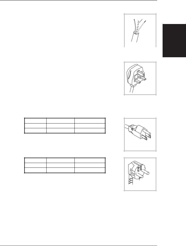
British
Country |
IEC 320 plug type |
IFR part number |
|
|
|
United Kingdom |
Straight through |
23422-001 |
|
|
|
United Kingdom |
Right angled |
23422-002 |
|
|
|
The UK lead is fitted with an ASTA approved moulded plug to BS 1363.
A replaceable 13 A fuse to BS 1362 is contained within the plug. This fuse is only designed to protect the lead assembly. Never use the plug with the detachable fuse cover omitted or if the cover is damaged.
EARTH
NEUTRAL
LIVE
UNITED KINGDOM
C3510
The fuse(s) or circuit breaker to protect the equipment is fitted at the back of the equipment.
North American |
|
|
|
|
Country |
IEC 320 plug type |
IFR part number |
|
|
North American |
Straight through |
23422-004 |
|
|
North American |
Right angled |
23422-005 |
EARTH |
|
The North American lead is fitted with a NEMA 5-15P (Canadian |
LIVE |
|||
|
||||
CS22.2 No 42) plug and carries approvals from UL and CSA for use in |
NEUTRAL |
|||
|
||||
the USA and Canada. |
|
|
||
|
|
|
U.S./CANADA/KOREA |
|
Continental Europe |
|
|
C3511 |
|
|
|
|
||
Country |
IEC 320 plug type |
IFR part number |
|
|
Europe |
Straight through |
23422-006 |
EARTH |
|
|
||||
Europe |
Right angled |
23422-007 |
LIVE |
|
|
|
|
||
The Continental European lead is fitted with a right angle IEC83 |
NEUTRAL |
|||
|
||||
standard C4 plug (CEE 7/7) which allows it to be used in sockets with |
EARTH |
|||
either a male earth pin (standard C 3b) or side earth clips (standard |
CONTINENTAL |
|||
C 2b) the latter is commonly called the German ‘Schuko’ plug. In |
||||
EUROPE |
||||
common with other Schuko style plugs, the plug is not polarized when |
C3512 |
|||
|
||||
fitted into a Schuko socket. The lead carries approvals for use in Austria, Belgium, Finland, |
||||
France, Germany, Holland, Italy, Norway and Sweden. Note that this plug will not fit Italian |
||||
standard CEI 23-16 outlets. The lead should not be used in Denmark given that the earth |
||||
connection will not be made. |
|
|
||
Français
Le câble d'alimentation d'Europe Continentale est muni d'un connecteur mâle à angle droit type CEI83, standard C4 (CEE 7/7), qui peut être utilisé dans une prise femelle à ergot de terre (standard C 3b) ou à clips latéraux (standard C 2b), cette dernière étant communément appelée prise “Schuko” allemande. De la même façon que les autres connecteurs de type Schuko, celui-ci n'est pas polarisé lorsqu'il s'adapte à une prise femelle Schuko. Ce câble d'alimentation est
INSTALLATION
46882-225U |
2-3 |

INSTALLATION
homologué en Allemagne, Autriche, Belgique, Finlande, France, Hollande, Italie, Norvège et Suède. A noter que ce connecteur n'est pas compatible avec les prises de courant italiennes au standard CEI 23-16. Ce câble ne doit pas être utilisé au Danemark à cause du défaut de connexion de masse.
Deutsch
Das kontinentaleuropäische Netzkabel ist mit einem rechtwinkeligen Stecker nach IEC83 C4 (CEE7/7) Standard versehen, welcher sowohl in Steckdosen mit Erde-Stift (Standard C 3b) oder seitlichen Erdeklemmen, im allgemeinen “Schukosteckdose” genannt, paßt. Üblicherweise ist der Schukostecker bei Verwendung in Schukosteckdosen nicht gepolt. Dieses Netzkabel besitzt Zulassung für Österreich, Belgien, Finnland, Frankreich, Deutschland, Holland, Italien, Norwegen und Schweden.
Hinweis: Dieser Schukostecker paßt nicht in die italienischen Standardsteckdosen nach CEI 23-16 Norm. Dieses Netzkabel sollte nicht in Dänemark verwendet werden, da hier keine Erdeverbindung hergestellt wird.
Español
El cable de alimentación tipo Europeo Continental dispone de una clavija C4 normalizada IEC83 (CEE 7/7) que permite su utilización tanto en bases de enchufe con toma de tierra macho (tipo C 3b) o con toma de tierra mediante contactos laterales (tipo C 2b) que, en este último caso, suele denominarse “Schuko”. Al igual que cualquier otra clavija tipo Schuko, las conexiones a red no están polarizadas cuando se conectan a una base tipo Schuko. El cable lleva autorización para su uso en Austria, Bélgica, Finlandia, Francia, Alemania, Holanda, Italia, Noruega y Suecia. Observe que este cable no se adapta a la norma italiana CEI 23-16. El cable no debe utilizarse en Dinamarca en el caso de no efectuarse conexión a tierra.
Italiano
I cavi d'alimentazione per l'Europa continentale vengono forniti terminati con una spina ad angolo retto del tipo C4 secondo lo standard IEC83 (CEE 7/7) che può essere usato in prese in cui la terra può essere fornita o tramite connettore maschio (C 3b) o tramite clips laterali (C 2b), quest'ultima comunemente detta di tipo tedesca “Schuko”. Questa spina, quando collegata ad una presa Schuko, non è polarizzata.
Il cavo può essere usato in Austria, Belgio, Finlandia, Francia, Germania, Olanda, Norvegia, Svezia ed Italia. E' da notare che per l'Italia questo non risponde allo standard CEI 23-16.
Questa spina non dovrebbe invece essere usata in Danimarca in quanto non realizza il collegamento di terra.
Goods-in checks
The following goods-in check verifies that the instrument is functioning correctly, but does not verify conformance to the listed specification. To verify that the instrument conforms to the specification given in Chapter 1, refer to Chapter 7, 'Acceptance testing'.
(1)Ensure that the correct fuse is fitted (accessible from the rear panel) and connect the instrument to the supply.
(2)Switch on and check that a display is present.
(3)If the instrument appears to be completely dead, carry out the following: Check that the mains power supply line is providing power to the instrument. Check that the mains fuses have not blown.
Instrument operating position
For reasons of stability and ventilation the instrument must only be operated on its underside feet (with or without the tilt stands).
2-4 |
46882-225U |
Loading...