

Page 1
For the very latest specifications visit www.aeroflex.com
AA nneeww,, ccoosstt eeffffeeccttiivvee RRFF tteessttiinngg ttooooll ffoorr tthhee RRFF pprrooffeessssiioonnaall wwhhoo ddeemmaannddss mmoorree ffrroomm aa
ccoommmmuunniiccaattiioonnss sseerrvviiccee mmoonniittoorr
Wireless
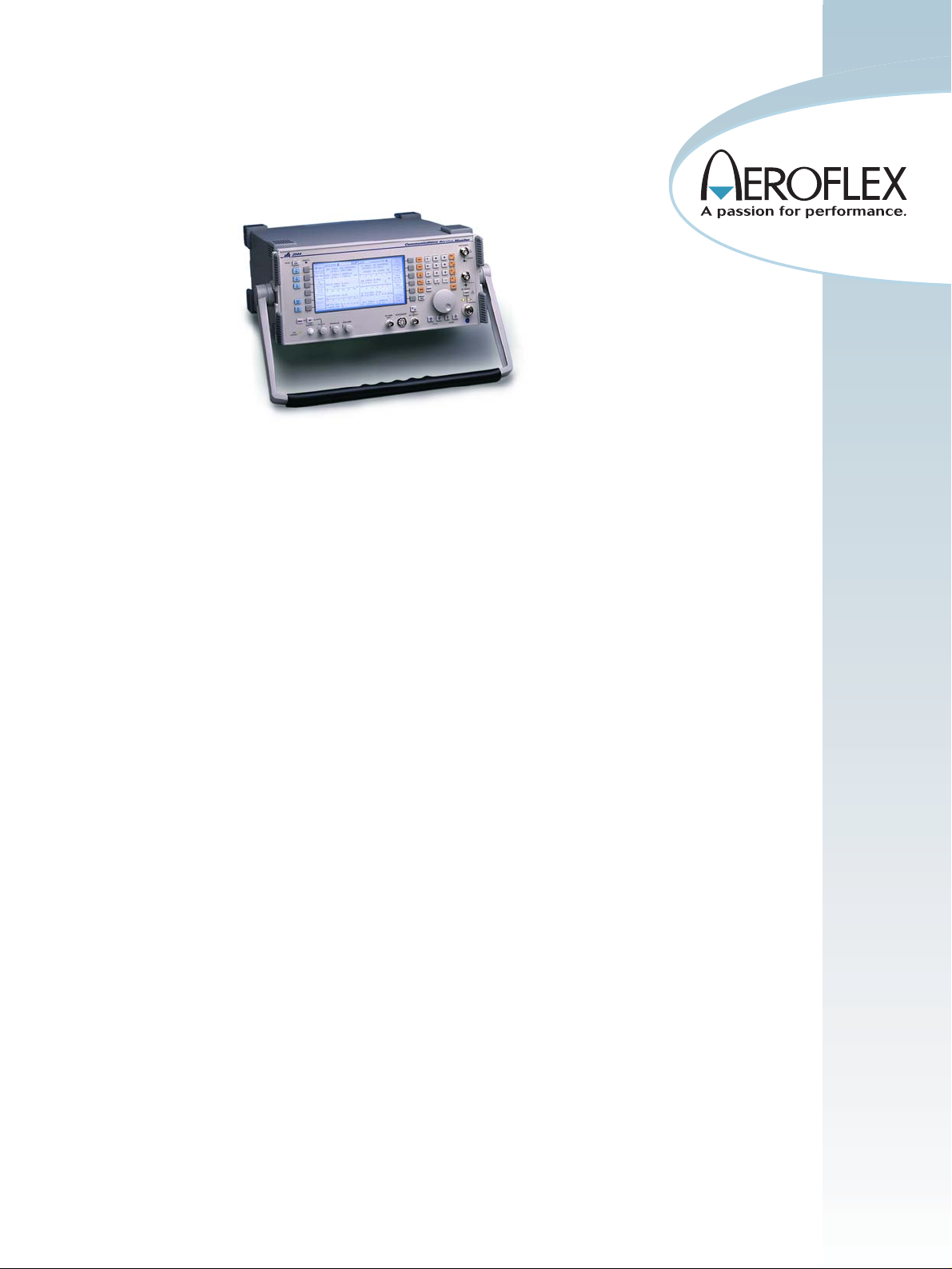
2944 Communications Service Monitor
• Automatically tunes to transmit signal
• Proven performance backed by IFR’s long
history of RF test excellence
• 0.5 ppm TCXO standard
• Duplex RF output levels down to
-141 dBm
• SSB phase noise better than -95 dBc/Hz
• Dual audio generators from 10 Hz to
25 kHz
• Narrow and broad band power meters
• Full function audio analysis tools
Audio bar charts
Audio voltmeters
Audio S/N meters
Audio distortion meters
Audio frequency meters
• Rugged lightweight package
• Full span spectrum analyzer with optional
tracking generator and offset tracking
• Accurate power measurements to 150 W
• 5 W protection on all RF ports standard
The 2944 Communications Service Monitor is
the lightest, most rugged service monitor available with a full performance spectrum analyzer
as standard. For field work the 2944 provides
an excellent combination of instruments for all
types of maintenance work. In the workshop, it
provides all of the performance you would
expect for exacting measurements.
Full Featured, High Accuracy, Low Cost
Designed for the wireless communications professional, the 2944,
shown with optional bail arm (OPT30), includes high powered accuracy and features at a very affordable cost. RF professionals involved
in day-to-day AM/FM measurements can use the 2944 to perform all
of their transmitter and mobile unit measurements without having
to pay for “extras” that add cost to other service monitors.
Field Operation
At under 12 kg (25 lbs.), the 2944 is the lightest RF Communications
Service Monitor on the market. Using the proven Aeroflex look and
feel of the 2945A series, the 2944 is ideal for carrying. The side handle ensures that the instrument is clear of stairs when ascending
buildings and the depth is suitable for the 2944 to be operated comfortably when it is placed on the floor.
With the optional bail arm, the 2944 allows a stowage cover to be fitted over the front panel for storage of adapters and further protection to the instrument’s front panel. Full operation is possible from
the “ever-ready” case so that your instrument is protected from transit damage.
Battery - Carry a Spare
The battery fits neatly into the “ever-ready” case and is easily
replaced with a spare when discharged. There is no memory effect
associated with the battery, even when partially discharged.
Fast Warm Up - Fast Results
The standard TCXO allows results to be made reliably within a
minute of switch on. Where even better stability is required, an
optional OCXO is available (OPT3). Stored settings may be recalled
from internal memory allowing fast and straightforward setup.
Page 2
Fast Full Performance Spectrum Analyzer - Provided as
Standard
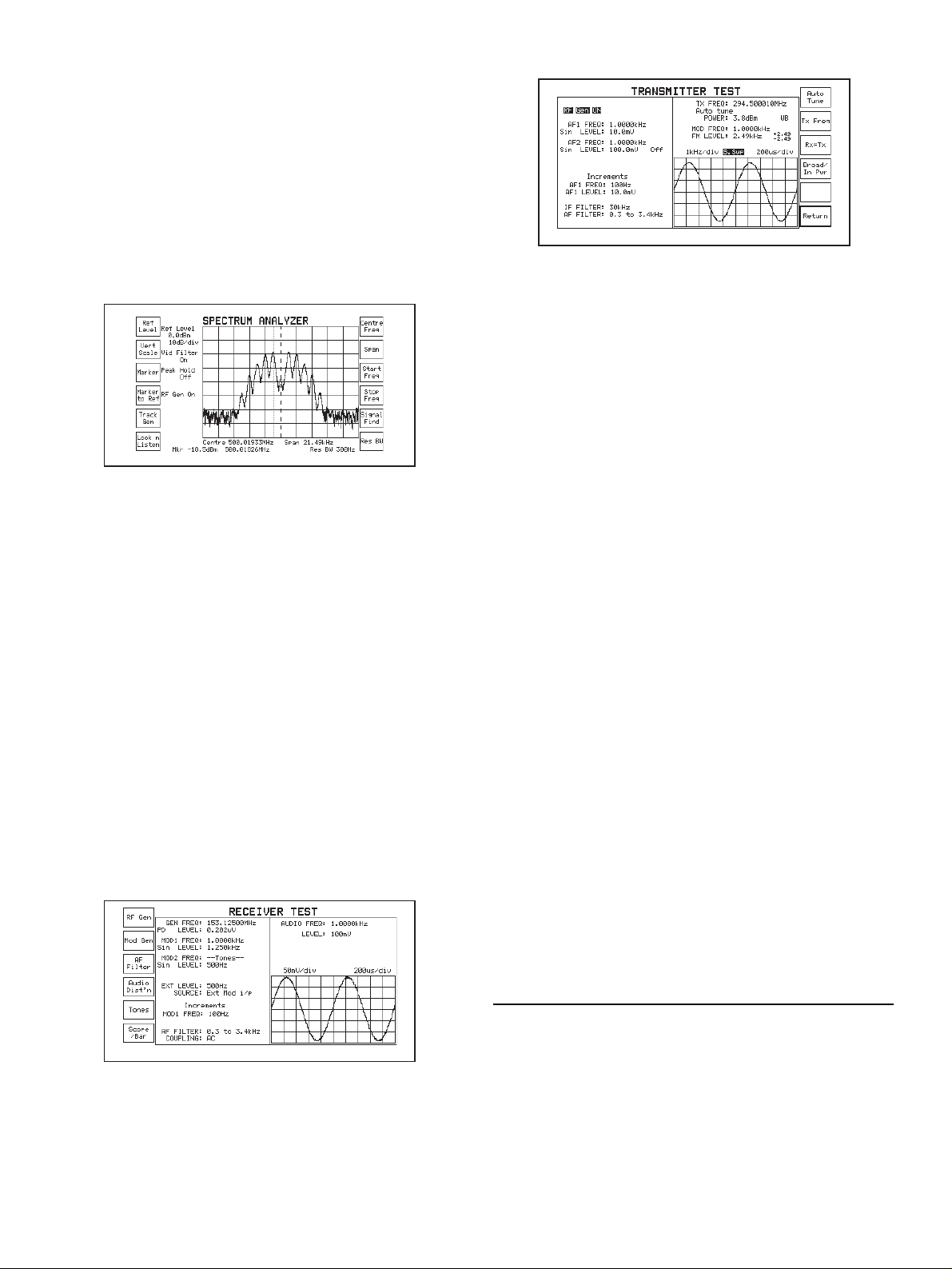
The spectrum analyzer provides spans from 100 Hz per division to
full span and has a fully adjustable reference level. Speed is comparable to analog analyzers, allowing real time adjustments over the displayed dynamic range. With the optional tracking generator, duplexers and filters can be aligned quickly and easily. An offset facility provides testing of equipment with frequency translation. Channel stepping can be performed by defining an increment and then using the
FREQ ×Ø keys. This is particularly useful when testing multi-channel systems.
High performance spectrum analyzer provided as a standard
feature
From 2 µV to 150 W
The 2944 will measure the power of low level signals such as those
encountered when monitoring off-air signals or those found when
probing a circuit. 150 W measurement is provided without the need
for external attenuators, so high power base stations can be measured
directly. Measurement accuracy of better than 10% is guaranteed all
the way down to 5 mW on the N-Type connector, allowing radios to be
qualified at low power levels.
Accurate RF Signals
The signal generator provides coverage from 400 kHz to 1.05 GHz
with +5 dBm output (+7 dBm overrange) and fast switching speed.
Level accuracy is ±2 dB at all levels above -127 dBm.
Duplex - Provided as Standard
Full duplex operation is provided by the 2944 allowing testing of
duplex radios as well as simultaneous testing of repeater transmit and
receive paths. There are no restrictions to the duplex offset.
2944 provides full duplex capability
Remote Control - RS-232 or GPIB
Remote control is provided with an RS-232 interface as standard. An
IEEE-488.2 interface (OPT5) can be fitted where other instruments
are required to operate in a system with the 2944.
Printing Made Easy
With the parallel printer port interface (OPT4), screen dumps, automatic test results or previously stored results may be sent to any parallel printer. These facilities are available as standard using the serial RS-232 interface. A screen capture facility is available so any screen
displayed can be saved direct to a PC, via the serial port, as a bitmap
file.
Audio Analysis
Full featured audio analysis tools include; audio bar charts, audio voltmeter, audio S/N meter, audio distortion meter and audio frequency
meter. A comprehensive range of filters is provided as standard,
including band pass, low pass and high pass. The direct measurement of CTCSS is possible with the 300 Hz LP filter, even with
speech present. Two full range audio generators are provided as standard for internal modulation or audio sources.
Comprehensive Oscilloscope
Analysis of audio signals, whether from the demodulated signal or the
audio input direct, can be viewed for further inspection. The oscilloscope can either be combined with the measurement screen in the
Tx, Rx or AF test modes or ‘zoomed’ to a full screen display.
Different levels of persistence can be selected to allow short or long
term effects to be captured.
Tones Generation and Decoding
The tones menus now include full remote control so that radio workshops can further automate their tasks. These and other improvements are in response to user feedback and allow better control of the
tones from the top level screens.
Page 3

For the very latest specifications visit www.aeroflex.com
SSPPEECCIIFFIICCAATTIIOONN
GGEENNEERRAALL IINNFFOORRMMAATTIIOONN
Certain characteristics are shown as typical. These provide additional
information for applying the instrument, but are unwarranted.
RRFF SSIIGGNNAALL GGEENNEERRAATTOORR
FREQUENCY
Frequency Range
400 kHz to 1.05 GHz
Resolution
10 Hz
Indication
10 digit display
Setting
Keyboard entry, delta increment/decrement function and rotary control
Accuracy
As frequency standard
OUTPUT LEVEL
Output Level Range
N-Type socket: -141 to -21 dBm
BNC socket: -115 to +5 dBm (overrange to +7 dBm)
Resolution
0.1 dB
Indication
4 digits plus sign (dBm, dBµV, µV, mV PD/EMF)
Accuracy
±2 dB for levels above -127 dBm on N-Type socket up to 1 GHz
Reverse Power Protection
N-Type: 50 W for 10 minutes, normal operation
150 W for 1 minute at 20°C
Overload indicated by audible and visual warning
BNC: 5 W Overload indicated by audible and visual warning
Output Impedance
Nominally 50 Ω
VSWR
N-Type
Better than 1.2:1 up to 500 MHz
Better than 1.35:1 up to 1.05 GHz
BNC
Better than 2.2:1 up to 1.05 GHz
SPECTRAL PURITY
(If you require even better spectral purity than that specified here,
please consider the 2948B)
Residual FM
<15 Hz RMS (0.3 to 3.4 kHz) up to 500 MHz
<20 Hz RMS (0.3 to 3.4 kHz) up to 1.0 GHz (with OCXO)
Harmonics
Better than -20 dBc
Spurious Signals
Better than -30 dBc (±10 kHz to 1.5 MHz offset from carrier frequency or over range 600 to 700 MHz)
Better than -40 dBc from 400 kHz to 1 GHz
SSB Phase Noise (20 kHz offset)
Better than -95 dBc/Hz up to 1 GHz
RF Carrier Leakage
Less than 0.5 µV Potential Difference generated in a 50
Ω
load by a 2
turn loop 25 mm from the case. Output level less than -40 dBm into
a sealed 50
Ω
load.
AMPLITUDE MODULATION - INTERNAL
Frequency Range
400 kHz to 1.05 GHz
AM Depth Range
0 to 99%
Resolution
1%
Indication
2 digits
Setting
Keyboard entry, delta increment/decrement function and rotary control
Accuracy
For carrier frequencies from 1.5 MHz to 400 MHz
±7% ±1 digit for modulation frequency of 1 kHz
±10% ±1 digit for modulation frequencies from 50 Hz to 5 kHz
±15% ±1 digit for modulation frequencies from 50 Hz to 15 kHz
Distortion
Less than 2% at 1 kHz for 30% AM, CCITT weighted
Modulation Frequency
20 Hz to 20 kHz
AMPLITUDE MODULATION - EXTERNAL
Input Impedance
Nominally 10 kΩ in parallel with 40 pF
Frequency Range
As internal AM
Modulation Frequency Range
As internal AM
Sensitivity
1 V RMS for 0 to 100% AM
FREQUENCY MODULATION - INTERNAL
Frequency Range
400 kHz to 1.05 GHz
Maximum Deviation
0 to 75 kHz
Indication
3 digits
Page 4

Setting
Keyboard entry, delta increment/decrement function and rotary control
Accuracy
(1)
±5% ± 10 Hz at 1 kHz modulating frequency
±10% at modulating frequencies from 50 Hz to 15 kHz
Distortion
<1% at 1 kHz for deviation of 5 kHz, CCITT weighted
Modulation Frequency Range
20 Hz to 25 kHz
Resolution
25 Hz
Pre-emphasis
750 µs selectable
FREQUENCY MODULATION - EXTERNAL
Input Impedance
Nominally 10 k
Ω
in parallel with 40 pF
Frequency Range
As internal FM
Modulation Frequency Range
DC to 100 kHz
Pre-emphasis
750 µs selectable
Sensitivity
1 Volt RMS for 0 to 75 kHz deviation
MICROPHONE INPUT
Input Level
2 mV to 200 mV (AGC levelled)
Input Impedance
Nominally 150 Ω
Press To Talk (PTT)
When using the optional microphone in Tx Test mode, the PTT will
switch instrument to Rx Test.
AAUUDDIIOO VVOOLLTTMMEETTEERR
Input Impedance
Nominally 1 MΩ in parallel with 40 pF
Frequency Range
DC and 50 Hz to 50 kHz
AC only 50 Hz to 50 kHz
Level Ranges
0 to 100 mV to 0 to 30 V RMS in a 1, 3, 10 sequence
Digital readout also in mW (user selectable)
Resolution
1 mV or 1% of reading
Indication
3 digits and bar-chart
Accuracy
±3% ±3 mV ±1 digit
AAUUDDIIOO FFRREEQQUUEENNCCYY MMEETTEERR
Frequency Range
20 Hz to 20 kHz
Resolution
0.1 Hz at <10 kHz
1 Hz at 10 kHz and above
Indication
5 digits
Accuracy
As frequency standard ±1 digit ± resolution
Sensitivity
50 mV
AAUUDDIIOO SSIINNAADD MMEETTEERR
Frequency
1 kHz
Range
0 to 18 dB and 0 to 50 dB
Resolution
0.1 dB
Indication
3 digits and bar-charts
Accuracy
±1 dB
Sensitivity
50 mV (100 mV for 40 dB SINAD) reading suppressed if audio voltage
is <5 mV
AAUUDDIIOO DDIISSTTOORRTTIIOONN MMEETTEERR
Frequency
1 kHz
Range
0 to 10%, 0 to 30% and 0 to 100%
Resolution
0.1% distortion
Indication
3 digits and bar-charts
Accuracy
±5% of reading ±0.5% distortion
Sensitivity
50 mV (100 mV for 1% distortion) reading suppressed if audio voltage
is <5 mV
Page 5

For the very latest specifications visit www.aeroflex.com
AAUUDDIIOO SS//NN MMEETTEERR
Range
0 to 30 dB and 0 to 100 dB
Resolution
0.1 dB
Indication
3 digits and bar-chart
Accuracy
±1 dB
Sensitivity
50 mV (100 mV for 40 dB S/N) reading suppressed if audio voltage is
<5 mV
AAUUDDIIOO OOSSCCIILLLLOOSSCCOOPPEE
Operating Modes
Single with digital storage on screen or repetitive sweep
Frequency Range
DC to 50 kHz, 3 Hz to 50 kHz AC coupled
Voltage Range
10 mV to 20 V per division in a 1, 2, 5 sequence
Voltage Accuracy
±5% of full scale
FM Ranges
±75, 30, 15, 6, 3 and 1.5 kHz deviation full scale, ±10% accuracy
AM Ranges
20, 10 and 5% per division, ±10% accuracy
Timebase
50 µs/div to 5 s/div in a 1, 2, 5 sequence
Graticule
10 Horizontal by 6 Vertical divisions
Special Features
Built in anti-aliasing circuitry and variable decode trigger level
AAUUDDIIOO BBAARR--CCHHAARRTTSS
Bar-chart Displays
AF Voltage, SINAD, Distortion, S/N
Vertical Resolution
2% of full scale
Ranging
Auto-ranging, range hold or manual selection
1, 2, 5, sequence with hysteresis
Audio and Modulation Filters
300 Hz, 3 kHz, 15 kHz Low pass
300 Hz to 3.4 kHz Bandpass
300 Hz High pass
750 µs de-emphasis
50 kHz Low pass (No filters applied)
Audio Analyzer General Features
Tones Mode
RRFF FFRREEQQUUEENNCCYY MMEETTEERR
Frequency Range
100 kHz to 1.05 GHz (manual tune)
10 MHz to 1 GHz (auto-tune)
Resolution
1 Hz or 10 Hz, selectable
Indication
Up to 10 digits
Accuracy
As frequency standard ± resolution
Acquisition Time
<1 second (manual tune)
Typically 3 seconds (auto-tune)
Sensitivity
Auto-tuned: 5 mW (N-Type)
0.05 mW (Antenna port)
Manual Tuned: -34 dBm (N-Type)
-60 dBm (Antenna port)
VSWR
N-Type: Better than 1.2:1 up to 500 MHz
Better than 1.25:1 up to 1.05 GHz
BNC: Better than 3:1 up to 1.05 GHz
RRFF PPOOWWEERR MMEETTEERR ((BBRROOAADDBBAANNDD))
Frequency Range
200 kHz to 1.05 GHz
Dynamic Range
5 mW to 150 W (N-Type)
0.05 to 250 mW (Antenna port)
Indication Units
W, dBm or dBW
Indication
3 digits or bar-chart
Resolution
0.1 dB maximum, typically 1%
Accuracy (N-Type)
±10% ± resolution up to 1 GHz
Maximum Continuous Rating
N-Type: 50 W at 20°C
Antenna port: 1 W
Intermittent Rating
N-Type: 150 W for limited periods, typically 1 minute at 20°C
Overload indicated by audible and visual warning
Page 6

MMOODDUULLAATTIIOONN MMEETTEERR
Sensitivity
Auto-tuned: 5 mW (N-Type)
0.05 mW (Antenna port)
Manual Tuned: -34 dBm (N-Type)
-60 dBm (Antenna port)
Audio & Modulation Filters
300 Hz, 3 kHz, 15 kHz Lowpass
300 Hz to 3.4 kHz Bandpass
300 Hz Highpass
750 µs de-emphasis
50 kHz Lowpass (No filters applied)
AMPLITUDE MODULATION
Frequency Range
100 kHz to 1.05 GHz
Modulation Frequency Range
10 Hz to 15 kHz
AM Depth Range
0 to 99% (manually tuned)
0 to 90% below 100 MHz
0 to 80%, 100 to 400 MHz
Resolution
1% AM
Indication
2 digits and bar-chart
Accuracy
(1)
±5% ±1 digit at 1 kHz
±8.5% ±1 digit, 50 Hz to 10 kHz
Demodulation Distortion
(1)
<2%, at 1 kHz and 30% AM (CCITT weighted)
Residual AM
<1% (300 Hz to 3.4 kHz)
FREQUENCY MODULATION
Frequency Range
100 kHz to 1.05 GHz
Modulation Frequency Range
10 Hz to 15 kHz
Deviation Range
0 to 75 kHz
Resolution
10 Hz below 2 kHz deviation
1% above 2 kHz deviation
Indication
3 digits and bar-chart
Accuracy
(1)
±5% ±1 digit at 1 kHz modulation frequency
±7.5% ±1 digit for modulation frequencies 50 Hz to 10 kHz
Demodulation Distortion
<2% at 1 kHz and 5 kHz FM (CCITT weighted)
Residual FM
<30 Hz (300 Hz to 3.4 kHz)
Demodulation Output Socket
200 mV peak to peak ±10% per 1 kHz deviation
RRFF SSPPEECCTTRRUUMM AANNAALLYYZZEERR
Frequency Range
100 kHz to 1.0 GHz
Spans
100 Hz/division to 100 MHz/division in a 1, 2, 5 sequence or continuously variable
Start - stop facility allows selection of infinitely variable span width
Resolution Bandwidth
300 Hz, 3, 30, 300 kHz, 3 MHz
Reference Level (top of screen)
-50 dBm to +52 dBm
0.7 mV to 71 V
Displayed Dynamic Range
80 dB
Noise Floor
Typically 75 dB below top of screen
On Screen Linearity
Typically ±2 dB ±1 resolution (10 dB/div) >10 dB above noise floor
Vertical Resolution
0.1 dB on 2 dB/division
0.5 dB on 10 dB/division
Level Flatness
±1 dB ± resolution over 50 MHz span
Intermodulation Distortion
Better than 70 dB for two signals at -30 dBm into first mixer
Sweep Speeds
10 ms/div to 200 ms/div in a 1, 2, 5 sequence (optimum sweep speed
and bandwidth selected according to span or user selectable)
Span Resolution Update
Bandwidth (Sweeps/sec)
10 kHz 300 Hz 5
100 kHz 3 kHz 9
1 MHz 30 kHz 9
10 MHz 300 kHz 9
100 MHz 300 kHz 5
1000 MHz 3 MHz 5
Marker Indication
Level and frequency or delta marker from center line of screen
Single marker for frequency and level display
Marker to center frequency
Page 7

For the very latest specifications visit www.aeroflex.com
∆ marker
Sensitivity
2 µV
AAUUDDIIOO GGEENNEERRAATTOORRSS
FREQUENCY
Frequency Range
10 Hz to 25 kHz (sine or square)
Setting
Keyboard entry, delta increment/decrement function and rotary control
Indication
5 digits
Resolution
0.1 Hz below 3.25 kHz
1 Hz above 3.25 kHz
Accuracy
0.01 Hz below 180 Hz, 0.1 Hz above 180 Hz
LEVEL
Level Range
0.1 mV to 4V RMS
Setting
Keyboard entry, delta increment/decrement function and rotary control
Indication
4 digits
Resolution
0.1 mV below 409 mV
1 mV above 409 mV
Accuracy
± 5% + resolution 50 Hz to 15 kHz
Output Impedance
Nominally 5 Ω (minimum load 25
Ω
)
Distortion
<0.5% at 1 kHz
<1%, 50 Hz to 15 kHz
Signaling Encoder / Decoder
Sequential tones functions including revert
User defined tones
Encodes and decodes up to 40 tones
CCIR, ZVEI, DZVEI, EEA, EIA or user defined
Any of the tones may be extended
Continuous, burst and single step modes available
Up to two frequency plans may be defined and stored within the 2944
for sequential tones
Any of the standard tone frequency plans may be copied to user
defined and modified
Tone length 20 ms to 1 s
Standard tone frequencies may be selected from a menu
Generation and decoding of DTMF tones
Generation and decoding of DCS (Digitally Coded Squelch)
Generation of POCSAG code CCIR No.1 Rec 584
Bit rates from 400 to 4800 bit/s. Inversion available
AUDIO MONITOR
Demodulated signals and audio signals may be monitored via the internal loudspeaker and the accessory socket output on the front panel.
FFRREEQQUUEENNCCYY SSTTAANNDDAARRDD
Internal Frequency Standard (TCXO)
Frequency
10 MHz
Temperature Stability
0.5 ppm, 0° to 40°C
0.6 ppm, 0° to 50°C
Ageing Rate
Better than 1 ppm per year
Warm-up
1 minute to specified accuracy
External Frequency Standard Input
Frequency
1, 2, 5 and 10 MHz
Input Level
>1 V peak to peak
Input Impedance
Nominally 1 kΩ
GGEENNEERRAALL
Keyboard and Display
Logical color coded keyboard with bright high resolution fast LCD
Display Size
160 x 85 mm
RS-232C
RS-232C interface is provided for printing and remote instrument control.
Connector
9 way female ‘D’ Type
POWER REQUIREMENTS
AC Supply Voltage
100 to 240 V (±10%)
AC Supply Frequency
90 - 264 V, 45 to 67 Hz
90 - 132 V, 45 to 440 Hz
Maximum AC Power
190 VA
Page 8

DC Supply Voltage
11 to 32 V
Maximum DC Power
100 W
Charge Output
13.8 V at 6 A maximum to charge a 12 V sealed lead acid battery
CALIBRATION INTERVAL
2 years
ELECTROMAGNETIC COMPATIBILITY
Conforms with the protection requirements of Council Directive
89/336/EEC. Complies with the limits specified in the following standards:
IEC/EN61326-1 : 1997, RF Emission Class B, Immunity Table 1,
Performance Criteria B
SAFETY
Conforms with the requirements of EWEC Council Directive 73/23/EEC
and Standard IEC/EN 61010-1 : 1993
Complies with IEC 1010-1 , BS EN61010-1 for class 1 portable
equipment and is for use in a pollution degree 2 environment. The
instrument is designed to operate from an installation category 1 or 2
supply.
Approved to UL3111-1
ENVIRONMENTAL
Rated Range of Use
0° to 50°C, up to 95% relative humidity at 40°C
Storage and Transport
Temperature
-40° to +71°C
Altitude
Up to 2500 m (pressurized freight at 27 kPa differential)
DIMENSIONS AND WEIGHT
380 mm wide, 178 mm high, 457 mm deep
15 in. wide, 7 in. high, 18 in. deep
(including handle, feet and covers)
Weight
<11.4 kg (<25 lbs.)
OOPPTTIIOONNSS AANNDD AACCCCEESSSSOORRIIEESS
600 ΩΩMATCHING UNIT (OPT1)
INPUT CIRCUIT
Impedance
600
Ω
Return Loss
>21 dB at 1 kHz
Frequency Response
±0.5 dB at 200 Hz to 5 kHz
±2 dB at 100 Hz to 20 kHz
Accuracy of 1:1 input:output ratio
±1% at 1 kHz ± accuracy of 2944
Maximum Input
5 V RMS maximum at 200 Hz to 5 kHz
3 V RMS maximum at 100 Hz to 20 kHz
OUTPUT CIRCUIT
Impedance
600
Ω
Return Loss
>21 dB at 1 kHz
Frequency response
±0.5 dB at 200 Hz to 5 kHz
±2 dB at 100 Hz to 20 kHz
Level Accuracy
±2% at 1 kHz ± accuracy of 2944
Output Level
1 mV to 2.5 V RMS across 600
Ω
HIGH STABILITY INTERNAL FREQUENCY (OCXO) STANDARD (OPT3)
Frequency
10 MHz
Temperature Stability
Better than 0.05 ppm, 5 to 55°C
Ageing Rate
Better than 0.1 ppm per year, after 1 month continuous use
Warm-up Time
<10 minutes to within 0.2 ppm at 20°C
PARALLEL INTERFACE (OPT4)
Allows direct connection of a parallel printer
Additionally provides four software programmable output lines
Printer Port
Connector
25 way female D type
Printers Supported
75, 100, 150 dots per inch laser printers, FX 80, FX 100 Epson format
Accessory Port
Connector
9 way female D type
Outputs
4 independently programmable output lines, each one configurable as
a logic line or as a relay contact closure. +5V supply available
GPIB (OPTION 5)
Capability
For printing, remote instrument control or for programming of user
defined test sequences.
Complies with the following subsets defined
Page 9

For the very latest specifications visit www.aeroflex.com
IEEE-488:- SH1, AH1, T6, L4, SR1, RL1, DT0, EI, DC1
SSB DEMODULATOR (OPTION 8)
The SSB demodulator allows signals to be demodulated either via the
internal loudspeaker or via the accessory socket. Provides demodulation of SSB signals (upper and lower sideband).
Frequency Range
400 kHz to 1 GHz
AF Demodulation Range
10 Hz to 15 kHz
Distortion
Typically less than 3% at 1 kHz (300 to 3.4 kHz)
Detection Range
2 µV to 150 W
Features
Automatic detection of USB or LSB. BFO can be used for tuning of
carrier for AM and FM radios.
CCITT FILTER (OPT23)
Allows a CCITT filter to be inserted into either the demodulated audio
path or the audio input path
CMESS FILTER (OPT24)
Allows a CMESS filter to be inserted into either the demodulated audio
path or the audio input path
LOOK AND LISTEN (OPT27)
Provides simultaneous spectrum display and demodulation of the centre frequency for span widths of 100 kHz, 200 kHz, 500 kHz and
1 MHz
Sensitivity 2 µV
TRACKING GENERATOR (OPT28)
Output specification as signal generator. A positive or negative frequency offset can be applied up to 999 MHz
BAIL ARM/FRONT COVER (OPTION 30)
Provides a bail arm carrying handle and front panel cover and storage
area. The bail arm will also provide additional viewing angles when
mounted on a bench.
BATTERY PACK
Type
12 V Sealed lead-acid
Connector XLR Type
Capacity
7 AH (30 minutes operation)
Weight
3 kg (6.6 lbs.)
Charge time from instrument
16 hours
VVEERRSSIIOONNSS AANNDD AACCCCEESSSSOORRIIEESS
When ordering please quote full ordering number information
Ordering Numbers
Versions
2944 Communications Service Monitor
Options
OPT1 600 Ω Matching Unit
OPT3 High Stability OCXO
OPT4 Parallel Interface †
OPT5 GPIB Interface †
OPT8 SSB Demodulator
OPT23 CCITT Filter ††
OPT24 CMESS Filter ††
OPT27 Look and Listen Addition to Spectrum Analyzer
OPT28 Tracking Generator
OPT30 Bail Arm and Front Panel Stowage Cover
Supplied Accessories
AC Supply Lead
DC Supply Lead
Operating Manual
Programming Manual
Optional Accessories
44991/145 Microphone with PTT
43113/021 Battery Pack for 2944
46662/571 ‘Ever-Ready’ Case
46662/616 ‘Ever-Ready’ Case for use with OPT30
54431/023 20 dB AF Attenuator (BNC)
54421/001 BNC Telescopic Antenna
46884/650 Serial Port to PC Control Cable (9 way)
46884/649 Serial Port to PC Control Cable (25 way)
46884/648 RS-232 Printer Cable (25 way)
59999/170 RF Directional Bridge
46880/106 Service Manual
Notes
(1)
At low modulation levels the residual AM/FM may become significant.
† Options 4 and 5 cannot be fitted together.
†† Options 23 and 24 cannot be fitted together.
Page 10

Page 11

For the very latest specifications visit www.aeroflex.com
Page 12

Part No. 46891/127, Issue 3, 03/04
CHINA
Tel: [+86] (10) 6467 2716
Fax: [+86] (10) 6467 2821
EUROPE
Tel: [+44] (0) 1438 742200
Fax: [+44] (0) 1438 727601
FRANCE
Tel: [+33] 1 60 79 96 00
Fax: [+33] 1 60 77 69 22
HONG KONG
Tel: [+852] 2832 7988
Fax: [+852] 2834 5364
SCANDINAVIA
Tel: [+45] 9614 0045
Fax: [+45] 9614 0047
SPAIN
Tel: [+34] (91) 640 11 34
Fax: [+34] (91) 640 06 40
UNITED KINGDOM
Tel: [+44] (0) 1438 742200
Toll Free: [+44] (0800) 282 388 (UK only)
Fax: [+44] (0) 1438 727601
USA
Tel: [+1] (316) 522 4981
Toll Free: [+1] (800) 835 2352 (US only)
Fax: [+1] (316) 522 1360
www.aeroflex.com
As we are always seeking to improve our products,
the information in this document gives only a general
indication of the product capacity, performance and
suitability, none of which shall form part of any contract. We reserve the right to make design changes
without notice. All trademarks are acknowledged.
Parent company Aeroflex, Inc. ©Aeroflex 2004.
 Loading...