

Page 1
Microwave
6210 Reflection Analyzer
66221100 eennhhaanncceess tthhee ccaappaabbiilliittyy ooff 66220000BB sseerriieess bbyy pprroovviiddiinngg pprreecciissiioonn rreefflleeccttiioonn ccooeeffffiicciieenntt aanndd ttiimmee
ddoommaaiinn mmeeaassuurreemmeennttss
• Excellent directivity and test port match
for precise measurements of reflection
coefficient
• Time domain software for pinpointing
impedance discontinuities in devices or
systems
• Polar and Smith Chart displays to facilitate matching of devices in circuits
• Fast sweep rate to speed up alignment of
components in production test
• Wide range of calibration kits for 3.5 mm,
Type N and 7 mm connectors
• Works with standard 6200 series
Microwave Test Set for easy upgrade
route
The 6210 Reflection Analyzer is designed specifically for precision measurements of reflection
coefficient from 250 MHz to 26.5 GHz. 6210 fits
underneath a 6200B series Microwave Test Set
(MTS) which provides the synthesized signal
source and analyzer display to form a single integrated test system. 6210 consists of additional
hardware and software to enable error corrected
reflection coefficient measurements with both
cartesian and polar displays.
an autotester. An analysis of return loss measurements using an
autotester shows that errors are dominated by test port match and
directivity. The 6210 Reflection Analyzer makes error corrected
return loss measurements to give improved accuracy and reduced
uncertainty. The test port match and directivity achieved with 6210
is significantly better than that obtainable from autotesters.
6210 performs precision reflection coefficient measurements
from 250 MHz to 26.5 GHz
Depending upon the test port connector and the quality of the calibration kit a test port match of >40 dB and directivity of >50 dB can
be achieved.
Accurate Return Loss Measurements
Reflection coefficient is the primary performance
test for microwave systems and components.
Return loss and VSWR are derivatives of reflection
coefficient, they can be measured with a standard
scalar analyzer and a directional RF bridge such as
For the very latest specifications visit www.aeroflex.com
Page 2
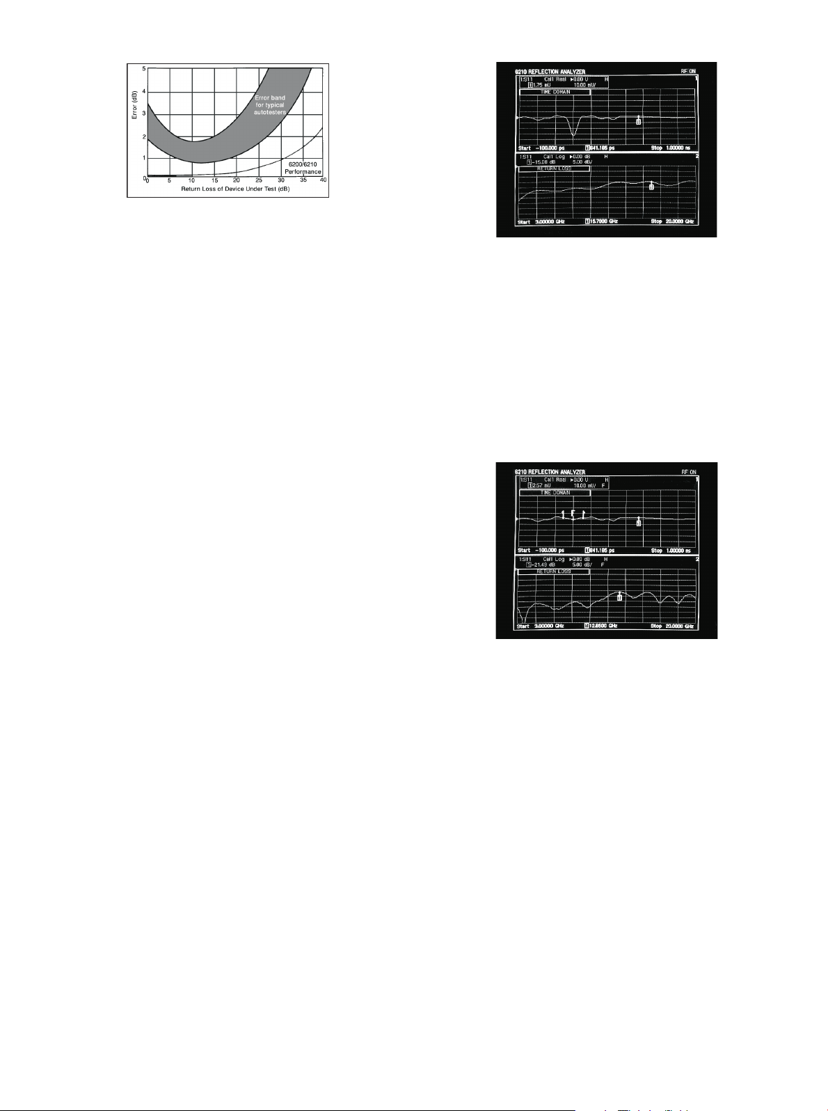
Improvement of accuracy obtained with 6210 compared to an
autotester.
In production areas this means less stand off due to measurement
uncertainty resulting in higher yield and shorter test and rework time.
To design engineers it means greater confidence in the quality of the
initial design.
The measurement can be displayed in log magnitude, linear magnitude, VSWR, phase, polar, real, imaginary or Smith Chart formats.
Integration of the synthesized source, reflection analyzer and display
unit into one system makes the 6210 ideal for both production testing
and design work. The soft key menu structure leads the user through
the measurement and prompts appear when data has to be entered.
Measurement setups and calibrations can be stored in the instrument
memory. The macro facility reduces test time in production areas by
automating repetitive test methods.
Time Domain Analysis
For design engineers early iterations of systems or components often
need trouble shooting. A poor return loss can be the result of bad
connector assembly, unoptimized track layout or incorrect component design. Time domain software gives a display of reflection coefficient against time (or distance) which simplifies diagnosis and pinpoints the problem area. The nature of the problem, capacitive or
inductive, can be identified from the reflection coefficient value.
Engineers can easily see if the device under test is faulty or needs
improved impedance matching between adjacent components.
Time domain works by performing an inverse Fourier transform on
the frequency domain data. Both lowpass and bandpass modes are
available. Lowpass mode simulates a traditional Time Domain
Reflectometer (TDR). It can be set up for both step and impulse
responses. Low-pass mode can only be used on devices whose frequency characteristics extend down to DC. For frequency selective
devices such as waveguide, filters and antennas bandpass mode must
be used. The display zoom feature can be used to examine the frequency range of interest with greater clarity rather than the complete
range of the calibration.
To overcome the effects of dispersion in waveguide a non linear
(warped) frequency sweep can be selected. A normal linear sweep
would blur the position of a discontinuity. Warped sweeps allow the
discontinuity to be pinpointed accurately.
Time domain response and return loss measurement of a
microwave component
Once a discontinuity has been identified the gating and fencing functions can be used to isolate it mathematically. Fencing allows the user
to see what the return loss would be without the effect of a particular
fault. Conversely gating allows the user to see what the return loss of
a specific fault or discontinuity is. These features are very powerful
tools for diagnosing and improving the performance of a system.
Knowing the position and severity of faults in a device means that they
can be modified in the shortest possible time, speeding up design
cycles.
For the same device shown previously, this display shows time
domain response with fence around fault and return loss of
device with effect of discontinuity removed
Complex Reflection Coefficient
When building up systems which include devices such as transistors,
PIN diodes, varactor diodes, capacitors and resistors, it is often necessary to fully characterize these devices. This allows prediction of
the performance of a circuit at an early stage of the design reducing
the number of design iterations. In order to match consecutive
devices in a circuit it is essential to have knowledge of the complex
reflection coefficient of each stage (input and output). This enables
a matching circuit to be designed to ensure the overall circuit performance meets its specification. 6210 can display complex reflection
coefficient in either polar or Smith Chart format. The accuracy of the
device characterization can be enhanced by using the time domain
gating function and electrical delay.
Page 3
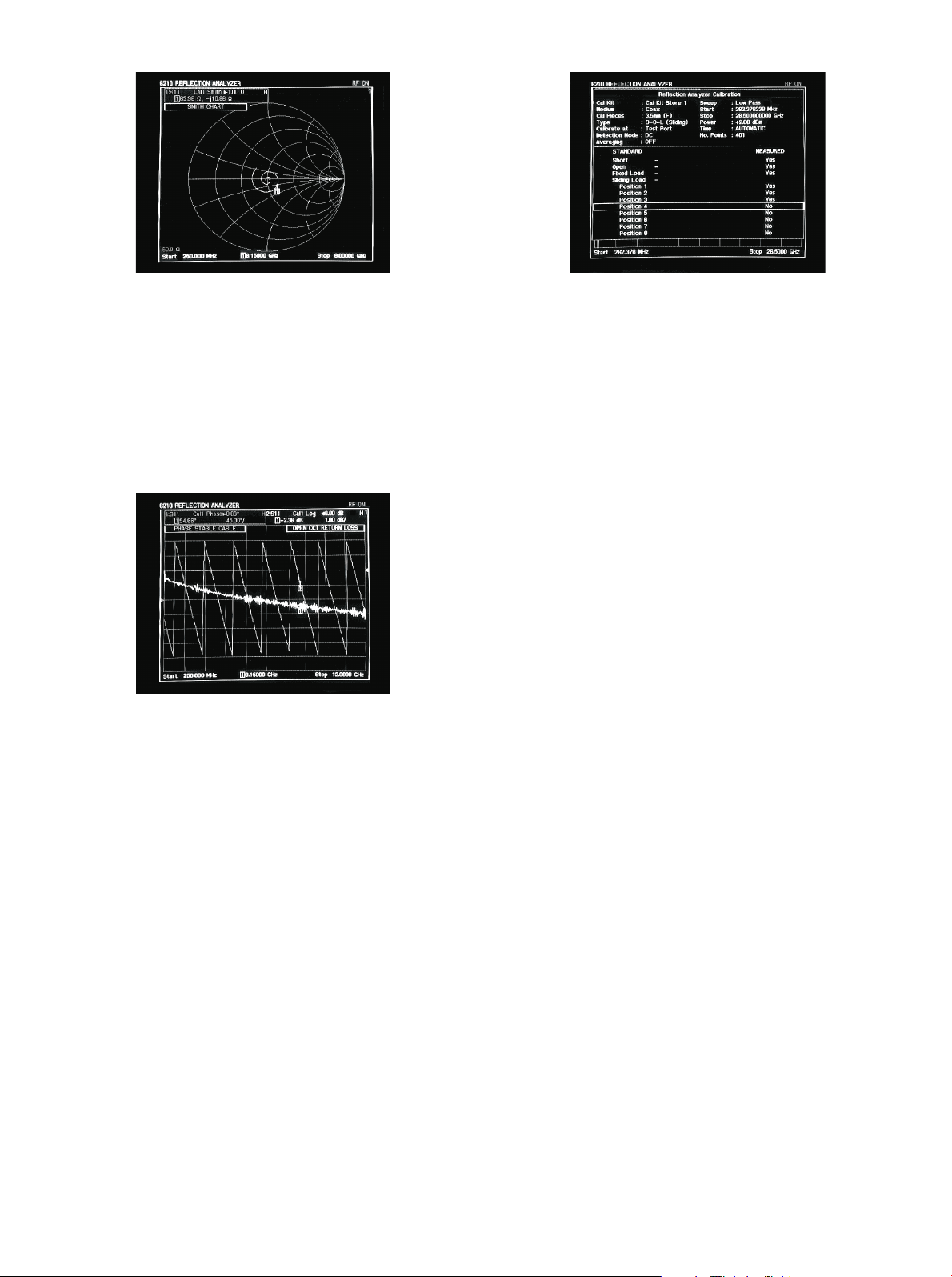
Smith Chart gives impedance information to aid design of
matching circuits
The electrical delay facility of 6210 allows the user to shift the reference plane. When characterizing devices on a substrate or in a test
fixture it is often necessary to shift the reference plane to the input of
the device. This removes the response of the length of transmission
line between the test port and the device input resulting in a display
of input impedance of the device.
Phase Display
Phase characteristics and open circuit return loss measurement
on a phase stable cable
The display can be formatted to show phase in degrees against frequency. This facility is invaluable for testing the phase stability of
cables and for phase matching lengths of transmission line such as
semi-rigid coax.
A cable with poor phase stability will introduce errors into measurements if moved after a calibration. Storing the phase characteristics
of a cable into a trace memory and then comparing with a live trace
enables the quality of the cable to be evaluated quickly.
Fast Calibration
An intuitive menu structure enables the user to quickly calibrate the
6210. Calibration kits are available for coaxial 3.5 mm, Type N and 7
mm connectors. Waveguide calibrations are also supported. A sliding load can give directivities of over 50 dB for coaxial measurements.
Screen displays lead the user through the calibration procedure
The overall performance of the 6210 is determined by the specification of the calibration kit used. The directivity, source match and
response errors can be characterized by measuring known standards.
Error correction routines in the 6210 then minimize errors during
normal measurements. IFR offer full calibration kits including short
and open circuits, fixed and sliding loads, connector gauges, test port
adapters and torque spanners. To verify calibrations optional airlines
are also available. The calibration kits are supplied in a protective
wooden storage box.
Economy calibration kits which include open and short circuits and
fixed loads are also available.
Active Device Measurement
For testing some active devices such as PIN and varactor diodes and
transistors it is necessary to have a biasing voltage on the output of the
test port. The optional bias tee (option 011) allows voltages to be
applied to the test port. The internal voltage/current source of the
MTS can be used as the supply.
Test Port Flexibility
The use of adapters at the test port to provide the most suitable test
port connector does not degrade measurement accuracy. This is
because calibration removes the effect of the adapter. Errors associated with scalar analyzers and autotesters using test port adapters are
therefore not encountered when using the 6210 Reflection Analyzer.
A range of ruggedized test port cables are available. Test port cables
allow error corrected measurements to be made remote from the
front panel connector with the choice of test port connectors including 3.5 mm male and female and Type N male and female or 7 mm.
All test port cables are phase stable so that repositioning the cable
after a calibration will still give good measurement accuracy.
Comprehensive Measurement System
A 6210 can be added to any 6200B series Microwave Test Set. All the
features of the 6200B are retained including absolute power measurement, frequency counter, voltage/current source, standard scalar
analyzer and synthesized sweep generator. The synthesizer can also
be used as a CW signal source.
6210 can be added to an MTS at any time giving an easy upgrade
route for users whose measurement requirements become more
demanding. The comprehensive marker functions, limit lines, scaling and plotting functions are all available when using the 6210
Reflection Analyzer.
For the very latest specifications visit www.aeroflex.com
Page 4

SSPPEECCIIFFIICCAATTIIOONN
Number of Test Ports
1 for the measurement of S11
Frequency Range (when used with)
6202B 250 MHz to 2 GHz
6201B 250 MHz to 8 GHz
6200B 250 MHz to 20 GHz
6203B or 6204B 250 MHz to 26.5 GHz
Dynamic Range (Noise Floor) (Source set to + 3 dBm)
250 MHz to 500 MHz >50 dB, 60 dB typical
500 MHz to 18 GHz >60 dB
18 GHz to 26.5 GHz > 50 dB, 60 dB typical
Insertion Loss from RF Input to Test Port
Typically 5 + (8 x f / 26.5) dB
where f is the set frequency in GHz
Number of Measurement Points
User selectable 2 to 800
SWEEP TIME
Auto
Sweep time is as fast as possible for the attributes selected
Manual
Sweep time will never be less than the sweep time entered and may
be greater depending on constraints imposed by the system hardware,
number of points and measurement software processing overhead.
Fastest time (401 points)
300 ms
Settable range
40 ms to 500 s
NOISE REDUCTION
Averaging
1 to 1000 (applied instrument wide)
Smoothing
0.01% to 20% of span, resolution 0.01%
CALIBRATION
Calibration Types - 1 Port
COAX WAVEGUIDE
short, open, fixed load short, offset short, fixed load
short, open, sliding load short, 2 x offset shorts
short, offset short sliding load.
In addition the ability to specify sex and connector type of the test port
Number of cal points
Same as number of measurement points
Calibration kits (optional)
Economy – Type N and 3 5 mm
Full – Type N, 3.5 mm and 7 mm
Calibration stores
4, with number of calibration points user selectable from 2 to 800
Additional storage is available via memory card (optional accessory)
REFLECTION ANALYZER SYSTEM PERFORMANCE
Dependent on calibration kit used. Specifications assume a 2 hour
warm up period from power on and an ambient temperature of 23°C
±3°C
N type calibration kit (economy)
Directivity
<2 GHz >40 dB
2 GHz to 18 GHz >30 dB
Source Match
<2 GHz >30 dB
2 GHz to 18 GHz >24 dB
Frequency response Within ±0.25 dB
N type calibration kit (full)
Directivity >40 dB
Source Match >30 dB
Frequency response Within ±0.2 dB
7 mm type calibration kit (full)
Directivity >50 dB
Source Match >40 dB
Frequency response Within ±0.1 dB
3.5 mm type calibration kit (economy)
Directivity
<2 GHz >40 dB
2 GHz to 26.5 GHz >25 dB
Source Match
<2 GHz >30 dB
2 GHz to 26.5 GHz >22 dB
Frequency response Within ±0.4 dB
3.5 mm type calibration kit (full)
Directivity >40 dB
Source match >30 dB
Frequency response Within ±0.2 dB
REFLECTION ANALYZER CHANNEL FEATURES
DOMAINS
Frequency
Modes
CW, F1-F2, CF/span, frequency list sweep, harmonic
frequency sweep, waveguide frequency sweep.
Ability to blank frequency information to be restored by PRESET.
Resolution
1 Hz settable
Six digits displayed on graticule
POWER
Sweep range
25 dB
85 dB with MTS attenuator option
Resolution
0.01 dB settable
Offset
Ability to enter offset (per channel) between source and display
TIME
Time domain response for impedance discontinuity analysis
Page 5

Stimuli
Lowpass step
Lowpass impulse
Bandpass impulse
Resolution (26.5 GHz sweep)
Reflection (in air transmission lines)
Lowpass 0.7 cm
Bandpass 1.4 cm
Point Spacing
<0.01 cm
Windowing
Kaiser Bessel - user definable.
Gating
User definable start, stop and shape.
Fencing
User definable start, stop and shape.
VOLTAGE/CURRENT
Ability to sweep rear panel V/l output in the range
–15 V to +15 V(±15 mV, 2.5 W max) or in the range
–150 mA to +150 mA (±300 mA, 1.25 W max)
Voltage resolution
1 mV
Current resolution
10 mA
REFLECTION ANALYZER CHANNEL FEATURES
RESPONSE
Format
Cartesian: Logarithmic magnitude, Linear magnitude, Phase, VSWR,
Real, Imaginary.
Polar: Smith and Inverse Smith chart, Logarithmic magnitude,
Linear magnitude.
Scaling
Magnitude - Log format 0.01 dB/div to 20 dB/div in 1, 2, 5 sequence
Lin format 10-12 units/div to 103 units/div
Phase - Cartesian: 0.1°/div to 180°/div
Polar: 45°/div
Reference Level Position
Any graticule line
Reference Level Value
–99.99 to +99.99 all units except VSWR
1 to 100 VSWR
MEASUREMENT MANIPULATION
Display
Display live measurement
Display trace memory
Display user defined expressions involving subtraction and division on a
live measurement and a trace memory
Measurement Hold applied per trace
Complex limit lines
Four stores of 12 segments each. Each segment defines an upper and
a lower limit line. Any store can be applied to any cartesian trace
MARKERS
Eight per trace, any one of which can be enabled to become the active
marker, plus a separate delta marker.
Marker domain resolution
Frequency - Six digits by default. User has the ability to select
Power - 0.01 dB
Voltage - 1 mV
Current - 10 mA
Marker Response Resolution
Magnitude Log 0.01 dB
Phase 0.01°
Marker functions
Active marker, delta marker, minimum, maximum, search left, search
right, ‘N-dB’ bandwidth, peak-to-peak response.
Reference Plane Extension
User definable
Electrical Delay - ±1 s maximum or ±300,000 km
Phase Offset - ±360° maximum
Non-Dispersive Media
Can enter delay as either physical length (m) or electrical delay (s).
Relative velocity (Vr) and relatively permittivity (er) may be entered.
Characteristic Impedance
User definable, default 50
Waveguide Cut Off Frequency
User definable
TEST PORT CONNECTOR
Ruggedized precision 3.5 mm male
Maximum Input Power - 0.5 W
POWER SUPPLY
Consumption - 50 W maximum (in addition to MTS)
SIZE
46 mm high, 325 mm wide 450 mm deep
WEIGHT
6.5 kg (including interconnecting cables and fixing kit)
OPTIONAL BIAS TEE
Bias Voltage Range - ±42 V
Current Range - 0.5 A max
Insertion Loss - <1.5 dB
1 Hz resolution
Lin Six digits
Ω
For the very latest specifications visit www.aeroflex.com
Page 6
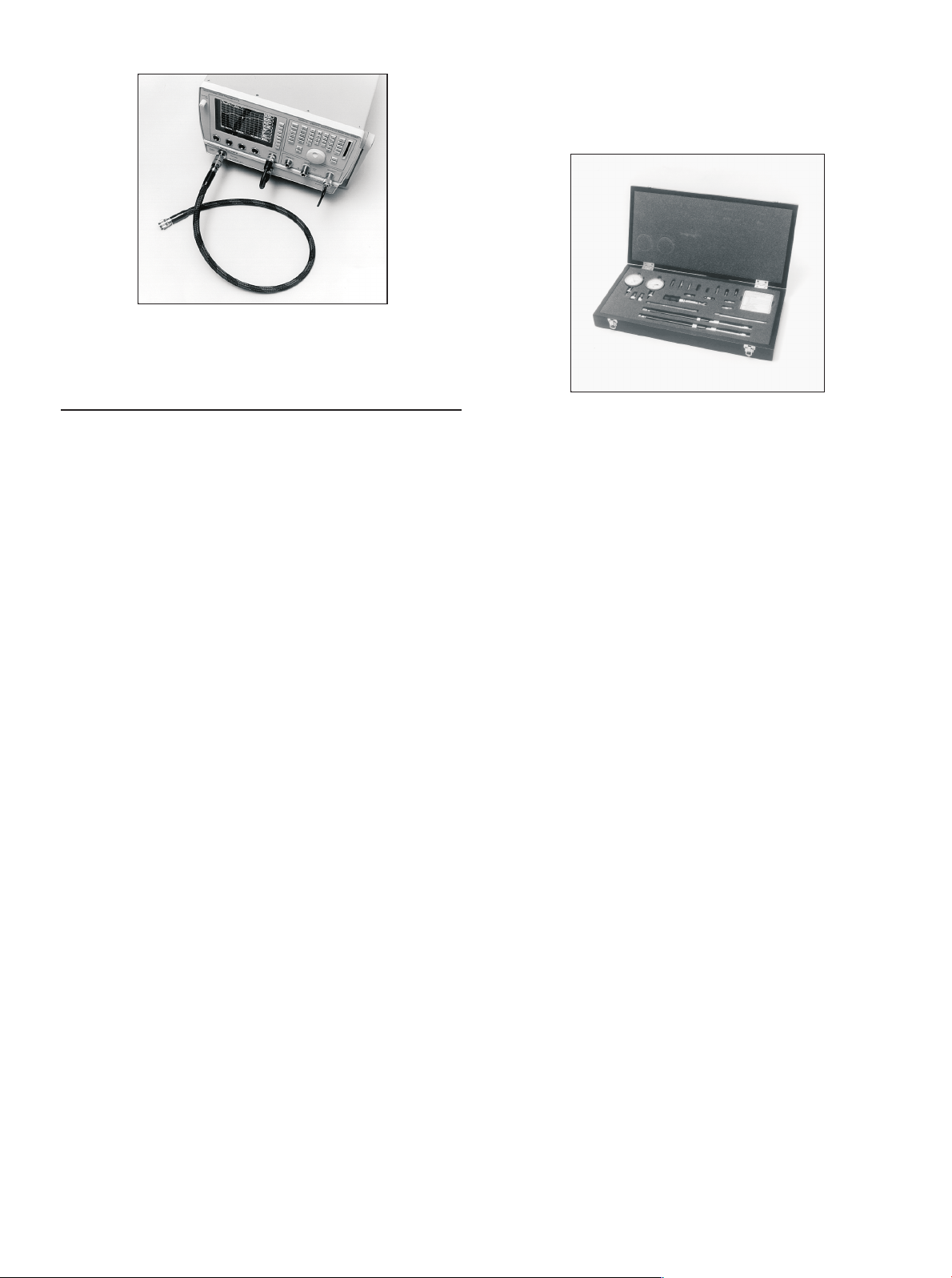
Ruggedized test port cables are available with 3.5 mm, Type N
and 7 mm connectors
VVEERRSSIIOONNSS AANNDD CCAALLIIBBRRAATTIIOONN KKIITTSS
ACCESSORIES
54112/157 Soft carrying case
54124/028 Front stowage cover for assembled MTS and 6210
When ordering please quote the full ordering number information.
REFLECTION ANALYZER
Order Numbers
6210 250 MHz to 26.5 GHz Reflection Analyzer
Options
Option 011 Bias tee
Option 012 Retrofit version
Supplied with
43138/328 Auxiliary signal channel cable
43138/283 Auxiliary data cable
43138/284 Auxiliary power cable
43138/366 RF interconnection cable – N type
43138/367 RF interconnection cable – 3.5 mm
Note: The 6210 Reflection Analyzer can be supplied as part of a system with one
of the 6200B series Microwave Test Sets above or as a retrofit version for fitting
to an existing 6200B series Microwave Test Set. Microwave Test Sets must be fitted with software issue 2.0 or higher. Contact your local IFR Service Center if a
software upgrade is required.
TEST PORT CABLES
Phase stability 0 2 x f (GHz) degrees
54311/155 Rugged 3.5 mm female to 7 mm
54311/156 Rugged 3.5 mm female to N type male
54311/157 Rugged 3.5 mm female to N type female
54311/158 Rugged 3.5 mm female to rugged 3.5 mm male
54311/159 Rugged 3.5 mm female to std. 3.5 mm female
50 Ω FIXED LOADS
Specification as for calibration kits
54421/009 7 mm Fixed Load
54421/010 3.5 mm (f) Fixed Load
54421/011 3.5 mm (m) Fixed Load
54421/012 N Type (f) Fixed Load
54421/013 N Type (m) Fixed Load
Full and Economy calibration kits are available with 3.5 mm,
Type N and 7 mm connectors
BOXED CAL KITS IN 3.5 MM
Order numbers
54424/009 Economy comprising
2 x short circuit (male and female)
2 x open circuit (male and female)
2 x fixed load (male and female)
Female/female precision adapter
Fixed load return loss
<2 GHz 40 dB
2 GHz to 26.5 GHz 25 dB
Optional Accessories
54425/005 Gauge kit (3.5 mm), comprising:- 2 x Gauges (m)
and (f), adapter and gauge blocks
54152/001 3.5 mm torque wrench
54311/164 3.5 mm male/male matched adapter
54311/165 3.5 mm male/female matched adapter
54424/007 Full comprising
As economy kit including optional accessories plus 2
x sliding load (male and female)
Optional Accessory
54425/003 Precision 15 cm airline (3.5 mm)
BOXED CAL KITS IN 7 mm
Economy not available
54424/001 Full comprising
Short circuit Open circuit
Fixed load Sliding load
Collet extractor Torque wrench
Gauge and gauge block
Rugged 3.5 mm (female) to 7 mm adapter
Fixed load return loss
<2 GHz 50 dB
2 GHz to 18 GHz 30 dB
Page 7

Optional Accessories
54425/001 Precision 30 cm airline (7 mm)
54311/163 Rugged 3.5 mm (female) to 7 mm adapter
54421/009 Fixed matched load (return loss as above)
BOXED CAL KITS IN TYPE N
Order numbers
54424/005 Economy comprising
2 x short circuit (male and female)
2 x open circuit (male and female)
2 x fixed load (male and female)
Rugged 3.5 mm to N(m) Adapter
Rugged 3.5 mm to N(f) Adapter
Fixed load return loss
<2 GHz 40 dB
2 GHz to 18 GHz 30 dB
Optional Accessories
54425/004 Gauge kit (N type), comprising:- 2 x Gauges (m)
and (f), adapters and gauge blocks
54311/166 N type male/male matched adapter
54311/167 N type male/female matched adapter
54311/168 N type female/female matched adapter
54424/003 Full comprising
As economy kit including optional accessories plus
2 x sliding load (male and female)
Optional Accessory
54425/002 Precision 30 cm airline (N type)
Note: Calibration kits and accessories carry a one year warranty excluding wear
and tear and misuse.
For the very latest specifications visit www.aeroflex.com
Page 8

CHINA Beijing
Tel: [+86] (10) 6467 2761 2716
Fax: [+86] (10) 6467 2821
CHINA Shanghai
Tel: [+86] (21) 6282 8001
Fax: [+86] (21) 62828 8002
FINLAND
Tel: [+358] (9) 2709 5541
Fax: [+358] (9) 804 2441
FRANCE
Tel: [+33] 1 60 79 96 00
Fax: [+33] 1 60 77 69 22
GERMANY
Tel: [+49] 8131 2926-0
Fax: [+49] 8131 2926-130
HONG KONG
Tel: [+852] 2832 7988
Fax: [+852] 2834 5364
INDIA
Tel: [+91] 80 5115 4501
Fax: [+91] 80 5115 4502
KOREA
Tel: [+82] (2) 3424 2719
Fax: [+82] (2) 3424 8620
SCANDINAVIA
Tel: [+45] 9614 0045
Fax: [+45] 9614 0047
SPAIN
Tel: [+34] (91) 640 11 34
Fax: [+34] (91) 640 06 40
UK Burnham
Tel: [+44] (0) 1682 604455
Fax: [+44] (0) 1682 662017
UK Stevenage
Tel: [+44] (0) 1438 742200
Fax: [+44] (0) 1438 727601
Freephone: 0800 282388
USA
Tel: [+1] (316) 522 4981
Fax: [+1] (316) 522 1360
Toll Free: 800 835 2352
www.aeroflex.com
As we are always seeking to improve our products,
the information in this document gives only a general
indication of the product capacity, performance and
suitability, none of which shall form part of any contract. We reserve the right to make design changes
without notice. All trademarks are acknowledged.
Parent company Aeroflex, Inc. ©Aeroflex 2004.
Our passion for performance is defined by three
attributes represented by these three icons:
solution-minded, performance-driven and customer-focused.
Part No. 46891/055, Issue 4, 12/03
 Loading...