

Aeroflex 8800 Operation Manual

Digital Radio
Test System
8800
Operation Manual
EXPORT CONTROL WARNING: This document contains controlled technical data under the
jurisdiction of the Export Administration Regulations (EAR), 15 CFR 730-774. It cannot be
transferred to any foreign third party without the specific prior approval of the U.S. Department of
Commerce, Bureau of Industry and Security (BIS). Violations of these regulations are punishable
by fine, imprisonment, or both.

OPERATION MANUAL
DIGITAL RADIO TEST SYSTEM
8800
PUBLISHED BY
Aeroflex
COPYRIGHT Aeroflex 2014
All rights reserved. No part of this publication may be reproduced, stored in a retrieval system, or
transmitted in any form or by any means, electronic, mechanical, photocopying, recording or
otherwise without the prior permission of the publisher.
Original Printing Jun 2014
10200 West York / Wichita, Kansas 67215 U.S.A. / (316) 522-4981 / FAX (316) 524-2623
Subject to Export Control, see Cover Page for details.

Electromagnetic Compatibility:
For continued EMC compliance, all external cables must be shielded and three meters or less in
length.
Nomenclature Statement:
In this manual, 8800, Test Set or Unit refers to the 8800 Digital Radio Test System.
Subject to Export Control, see Cover Page for details.

THIS PAGE INTENTIONALLY LEFT BLANK.
Subject to Export Control, see Cover Page for details.

SAFETY FIRST: TO ALL OPERATIONS PERSONNEL
REFER ALL SERVICI NG OF UNIT TO QUALIFIED TECHNI CAL PERSONNEL. THIS UNIT CONTAI NS NO
OPERATOR SERVICE ABLE PARTS.
WARNING: USING THIS EQUIP MENT IN A MANNER NOT SPECIFIED BY THE ACCOMPANYING
CASE, COVER OR PANEL REMOVAL
Opening the Case Assembly ex poses the operator to electrical hazards t hat can result in electrical shock or
equipment damage. Do not operate this Tes t Set with the Case Assembly open.
SAFETY IDENTIF ICATION IN TECHNICAL MANUAL
This manual uses the followi ng terms to draw attention to possible saf ety hazards, that may exist when
operating or servicing this equi pment.
CAUTION: THIS TERM IDENTI FIES CONDITIONS OR ACTIVI TIES THAT, IF IGNORED, CAN RESULT IN
WARNING: THIS TERM IDENTI FIES CONDITIONS OR ACTIVIT IES THAT, IF IGNORED, CAN RES ULT IN
SAFETY SYMBOLS IN MANUALS AND ON UNITS
DOCUMENTATION MAY IM PAIR THE SAFETY PROTECTION PROVIDED BY THE EQUIPMENT.
EQUIPMENT OR PROPERTY DAMAGE (E.G., FIRE).
PERSONAL INJURY OR DEATH.
CAUTION: Refer to accompanying doc uments. (This symbol refers to s pecific CAUTIONS
represented on the unit and clarified in t he text.)
AC OR DC TERMINAL: Terminal that m ay supply or be supplied with AC or DC voltage.
DC TERMINAL: Terminal that may supply or be supplied with DC voltage.
AC TERMINAL: Terminal that m ay supply or be supplied with AC or alternating volt age.
EQUIPMENT GROUNDING PRECAUTION
Improper grounding of equipment can result i n electrical shock.
USE OF PROBES
Check the specificat ions for the maximum voltage, current and power rati ngs of any connector on the Test Set
before connecting it with a probe from a terminal device. Be sure the terminal devi ce performs within these
specifications bef ore using it for measurement, to prevent elect rical shock or damage to the equipment.
POWER CORDS
Power cords must not be frayed, broken nor expose bare wiring when operating this equipment.
USE RECOMMENDED FUS ES ONLY
Use only fuses speci fically recommended for the equipment at the s pecified current and voltage ratings.
INTENDED USE
The 8800 is intended for indoor use only and should not be subj ected to conditions which cause water or other
liquids to collect on t he Touch Screen Display.
INTERNAL BATTERY
This unit contains a Lit hium Ion Battery, serviceable only by a qualified technician.
CAUTION: SIGNAL GENERATORS CAN BE A SOURCE OF ELECTROMAGNETIC INTERFERENCE (EM I) TO
COMMUNICATION RECEI VERS. SOME TRANSMITTED SIGNALS CAN CAUSE DIS RUPTION AND
INTERFERENCE TO COM MUNICATION SERVICES OUT T O A DISTANCE OF SEVERAL MILES.
USERS OF THIS EQUIPMENT SHOULD SCRUTINI ZE ANY OPERATION THAT RE SULTS IN
RADIATION OF A SI GNAL (DIRECTLY OR INDIRECTLY) A ND SHOULD TAKE NECESSARY
PRECAUTIONS TO AVOID POTENT IAL COMMUNICATION INTERFE RENCE PROBLEMS.
Subject to Export Control, see Cover Page for details.

THIS PAGE INTENTIONALLY LEFT BLANK.
Subject to Export Control, see Cover Page for details.

DECLARATION OF CONFORMITY
The Declaration of Conformity Certificate included with
the Unit should remain with the Unit.
Aeroflex recommends the operator reproduce a copy of
the Declaration of Conformity Certificate to be stored
with the Operation Manual for future reference.
Subject to Export Control, see Cover Page for details.

THIS PAGE INTENTIONALLY LEFT BLANK.
Subject to Export Control, see Cover Page for details.

RoHs Product Inform ation for People’s Republi c of China
Toxic or Hazardous Substance Content Table
The table provided below lists information as require d by People’s Republic of China
Electronic Industry Standard SJ/T 11364-2006, Marking for Control of Pollution Caused by
Electronic Information Products. The table lists toxic or hazardous substances c ontained in
Aeroflex products that exceed limits in SJ/T 11363-2006
Table 1. Toxic or Hazardous Subs tances in Product
部件名称
Parts
印刷板组件
Printed Board
Assemblies
机箱子组件
Chassis
subassembly
电源
Power Supply
电缆及电缆组件
Cables & Cable
Assemblies
O: Indicates that the toxic or hazardous substance contained in all of the homogenous
materials for this component is below the limit requirement in SJ/ T11363-2006
Lead
(Pb)
铅 汞 镉 六价铬 多溴联苯 多溴二苯醚
X O O O O O
X O O O O O
X O O O O O
X O O O O O
Toxic or Hazardous Substa nces 有毒有害物质或元素
Mercury
(Hg)
Cadmium
(Cd)
Hexavalent
Chromium
(Cr6+)
Polybrominated
Biphenyls (PBB)
Polybrominated
Diphenyl Ethers
(PBDE)
O: 表示该有毒有害物质在该部件所有均质材料中的含量均在 SJ/T 11363-2006
标准规定的限量要求以下
X: Indicates that the toxic or hazardous substance contained in at least one of the
homogeneous materials for this component is abo ve the limit requirement in SJ/T11363-
2006.
X: 表示该有毒有害物质至少在该部件的某一均质材料中的含量超出 SJ/T 11363-2006
标准规定的限量要求
Subject to Export Control, see Cover Page for details.

RoHs Product Inform ation for People’s Republ ic of China (cont)
Pollution Control Marking
The following marking is located on all Aeroflex products sold in China. The number in the
center indicates the Environmental Protection U se Period. This indicates the period in years
during which the hazardous substan ces described in Table 1 will not leak or mutate under
normal operating conditions so that the use of the prod uct will not result in any severe
environmental problem, any bodily injury, or damage to as sets. The Environmental Protection
Use period is valid only when the product is oper ated under the conditions defined in the
product manual.
Subject to Export Control, see Cover Page for details.

PREFACE
SCOPE
This Manual contains Instructions for operating the 8800. It is strongly recommended that the
Operator be thoroughly familiar with this manual before attempting to operate the equipment.
ORGANIZATION
The Manual is composed of the following Chapters:
CHAPTER 1 - INTRODUCTION
Provides an Introduction and a Brief Overview of Functions and Features. Principles of
Operation are also included.
CHAPTER 2 - OPERATING INSTRUCTIONS
Identifies and functionally describes all Controls, Indicators and Connectors.
Provides UI interaction.
Provides a Turn-On Procedure and Initial Adjustments.
Provides Operation Procedures.
Provides Applications.
CHAPTER 3 - OPERATOR MAINTENANCE
Identifies and explains Routine Service, Troubleshooting, Maintenance and Storage
Procedures.
Subject to Export Control, see Cover Page for details. i

TABLE OF CONTENTS
PARAGRAPH PAGE
CHAPTER 1 - INTRODUCTION
1-1 General Information ..................................................................................... 1-1
1-1A Scope .................................................................................................... 1-1
1-1B Nomenclature Cross-Reference List ........................................................... 1-1
1-2 Equipment Capabilities and Features ............................................................. 1-2
1-2A Capabilities ............................................................................................ 1-2
1-2B Features ................................................................................................. 1-3
1-3 Equipment Data ........................................................................................... 1-5
1-4 Principles of Operation ................................................................................. 1-19
CHAPTER 2 - O PERATING INSTRUCTIONS
2-1 Operator’s Controls, Indicators and Connectors .............................................. 2-1
2-2 Functions and Tiles ..................................................................................... 2-5
2-2-1 System Icons .......................................................................................... 2-7
2-2-2 Touch Screen .......................................................................................... 2-10
2-2-3 User Interface (UI) Components ................................................................ 2-11
2-2-3A Launch Bar ......................................................................................... 2-11
2-2-3B Function Icons .................................................................................... 2-12
2-2-3C Tile Windows ...................................................................................... 2-13
2-2-3D Defining Parameters ............................................................................ 2-16
2-2-3E Dropdown Menus ................................................................................. 2-20
2-2-3F Message Windows ............................................................................... 2-22
2-2-4 System Menu .......................................................................................... 2-23
2-2-5 Suspend (Sleep) Mode ............................................................................. 2-24
2-2-6 Multi-Language Support ........................................................................... 2-26
2-3 Preventive Maintenance Checks and Services ................................................. 2-28
2-3-1 General .................................................................................................. 2-28
2-3-2 Preventive Maintenance Procedures .......................................................... 2-28
2-3-2A Tools, Materials and Equipment Required .............................................. 2-28
2-3-2B Routine Checks ................................................................................... 2-28
2-3-2C Schedule of Checks ............................................................................. 2-28
2-4 Operation Under Usual Conditions ................................................................. 2-29
2-4-1 Turn-On Procedure .................................................................................. 2-29
2-4-2 Install/Remove License ............................................................................ 2-30
2-4-3 Install Software ....................................................................................... 2-34
2-4-4 Save/Recall Function Windows .................................................................. 2-37
2-4-5 Snapshot ................................................................................................ 2-38
2-4-6 Clone Unit .............................................................................................. 2-41
2-5 Basic Setups ............................................................................................... 2-42
2-5-1 Analog Demod ......................................................................................... 2-42
2-5-2 Analog SINAD ......................................................................................... 2-44
2-5-3 Digital DMR ............................................................................................ 2-46
ii Subject to Export Control, see Cover Page for details.

PARAGRAPH PAGE
CHAPTER 3 - MAINTENANCE
3-1 Service Upon Receipt ................................................................................... 3-1
3-1-1 Service Upon Receipt of Material .............................................................. 3-1
3-1-1A Unpacking .......................................................................................... 3-1
3-1-1B Checking Unpacked Equipment ............................................................. 3-2
3-1-2 Preliminary Servicing and Adjustment of Equipment .................................... 3-3
3-2 Self Test ..................................................................................................... 3-4
3-3 Troubleshooting .......................................................................................... 3-5
3-4 Maintenance Procedures .............................................................................. 3-9
3-4-1 Battery Recharging .................................................................................. 3-9
3-4-2 Battery Replacement ................................................................................ 3-10
3-4-3 Fuse Replacement ................................................................................... 3-11
3-4-4 DMM Fuse Replacement ........................................................................... 3-12
3-4-5 Feet Replacement.................................................................................... 3-13
3-5 Preparation for Storage or Shipment .............................................................. 3-14
3-5A Packaging ............................................................................................. 3-14
3-5B Environment ............................................................................................ 3-14
APPENDICES
A Connector Pin-Out Tables ............................................................................. A-1
A-1 I/O Connectors ........................................................................................ A-1
A-2 MIC Connector Pin-Out Table.................................................................... A-3
A-3 REMOTE Connector Pin-Out Table ............................................................ A-4
A-4 ETHERNET Connector Pin-Out Table ......................................................... A-5
A-5 USB Connector Pin-Out Table ................................................................... A-6
B Abbreviations ............................................................................................. B-1
INDEX
Subject to Export Control, see Cover Page for details. iii

LIST OF ILLUSTRATIONS / TABLES
LIST OF TABLES
TITLE PAGE
I/O Connectors (Front Panel) A-1
I/O Connectors (Rear Panel) A-2
MIC Connector Pin-Out Table A-3
REMOTE Connector Pin-Out Table A-4
ETHERNET Connector Pin-Out Table A-5
USB Connector Pin-Out Table A-6
iv Subject to Export Control, see Cover Page for details.

SERVICE UPON RECEIPT OF MATERIAL
Unpacking
Special-design packing material inside the shipping container provides maximum protection for the
8800. Avoid damaging the shipping container and packing material during equipment unpacking.
Use the following steps for unpacking the 8800.
l Cut and remove the sealing tape on top of the shipping container and open the shipping
container.
l Remove the top packing mold.
l Remove 8800 and packing material from the bottom packing mold.
l Remove the protective plastic bag from the 8800 and inspect the contents.
l Place the protective plastic bag and packing material inside the shipping container.
l Store the shipping container for future use should the 8800 need to be returned/shipped.
Checking Unpacked Equipment
Use the following steps for checking the equipment.
l Inspect the equipment for damage incurred during shipment. If the equipment has been
damaged, report the damage to Aeroflex Customer Service.
l Review the packing slip to verify the shipment is complete. The packing slip identifies the
standard items as well as the purchased Options. Report all discrepancies to Aeroflex.
CONTACT: Aeroflex
Telephone: (800) 835-2350 (U.S. only)
(316) 522-4981
FAX: (316) 524-2623
E-Mail: americas.service@aeroflex.com
Subject to Export Control, see Cover Page for details. v

Checking Unpacked Equipment (cont)
STANDARD ITEMS
DESCRIPTION PART NUMBER QTY
8800 Digital Radio Test System 112581 1
External DC Power Supply 67374 1
Fuse, Spare (5 A, 32 Vdc, Mini-Blade) 56080 2
Manual, Getting Started (Paper) (English)
Manual, Operation (CD) (English)
Power Cable (AC) (China) 91803 1
Power Cable (AC) (Continental Europe) 27480 1
Power Cable (AC) (North America) 27478 1
Power Cable (AC) (UK) 27477 1
113615 1
113613 1
vi Subject to Export Control, see Cover Page for details.
Checking Unpacked Equipment (cont)
8800
112581
External DC Power Supply
67374
Fuse, Spare (5 A, 32 Vdc, Mini-Blade)
56080
Power Cable (AC) (China)
91803
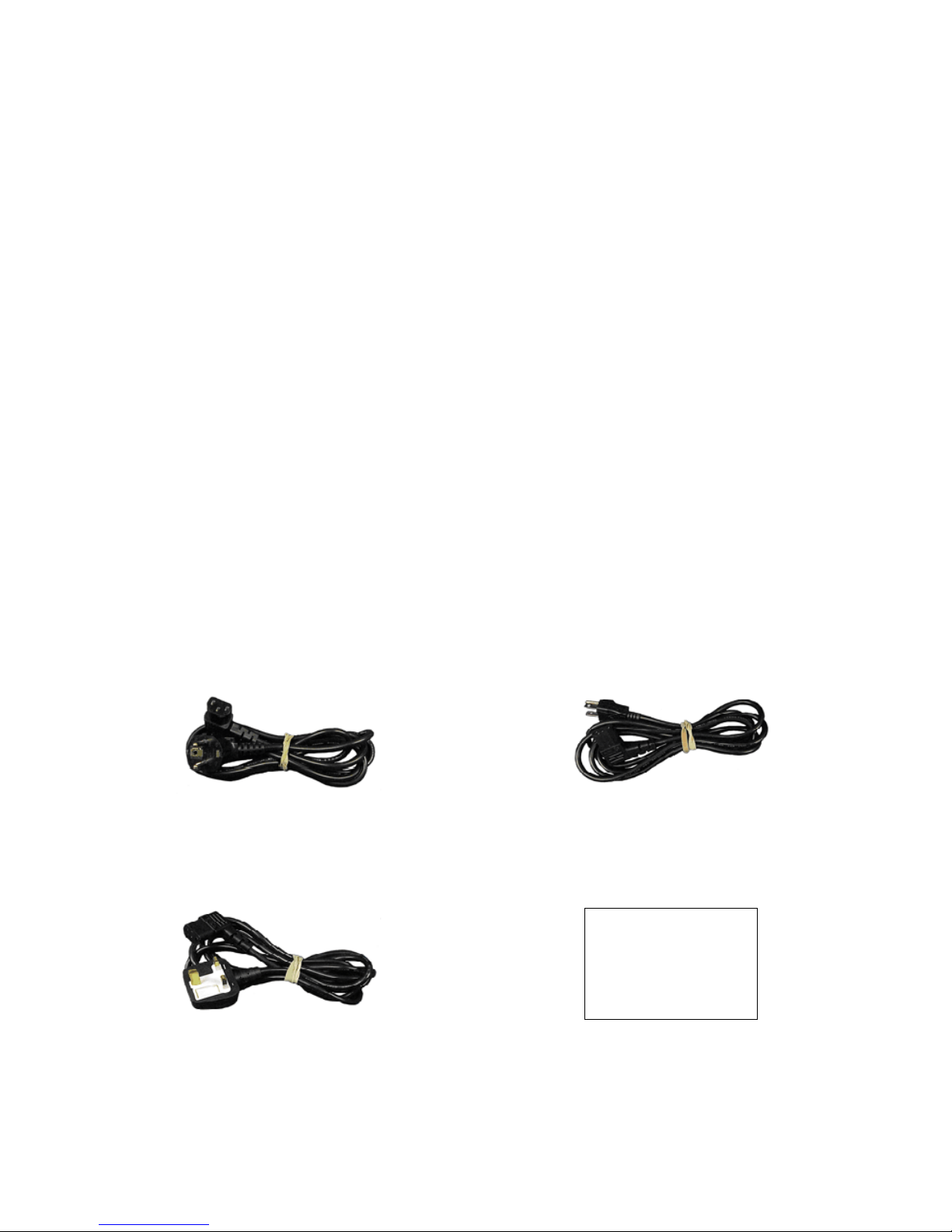
Power Cable (AC) (Continental Europe)
27480
Power Cable (AC) (North America)
27478
8800
Digital Radio Test System
Getting Started Manual
EXPORT CONTROLWARNING: This document contains controlled technical data under the jurisdiction
of the ExportAdminis tration Regulations (EAR), 15 CFR 730-774. It cannot be transferred to any foreign
third party without the specific prior approval of the U.S. Department of Comme rce, Bureau of Industry
and Security (BIS). Violations of these regulations are punishable by fine, imprisonment, or both.
Power Cable (AC) (UK)
27477
Manual, Getting Started (Paper) (English)
113615
STANDARD ITEMS
Subject to Export Control, see Cover Page for details. vii

Checking Unpacked Equipment (cont)
Manual, Operation (CD) (English)
113613
STANDARD ITEMS
viii Subject to Export Control, see Cover Page for details.

Checking Unpacked Equipment (cont)
OPTIONAL ITEMS
(These optional items may be included if ordered)
DESCRIPTION PART NUMBER QTY
Manual, Getting Started (Paper)
Arabic
Chinese - Simplified
Chinese - Traditional
French
German
Japanese
Korean
Malay
Polish
Portuguese
Russian
Spanish
Manual, Maintenance (CD) (English) 113614 1
Manual, Operation (CD)
Arabic
Chinese - Simplified
Chinese - Traditional
French
German
Japanese
Korean
Malay
Polish
Portuguese
Russian
Spanish
113699
113698
1
1
Subject to Export Control, see Cover Page for details. ix

Checking Unpacked Equipment (cont)
Manual, Getting Started (Paper)
(Spanish)
Manual, Maintenance (CD) (English)
Manual, Operation (CD)
(Spanish)
OPTIONAL ITEMS
(Arabic)
(Chinese - Simplified) 113699
(Chinese - Traditional)
(French)
(German)
(Japanese)
(Korean)
(Malay)
(Polish)
(Portuguese)
(Russian)
113614
(Arabic)
(Chinese - Simplified) 113698
(Chinese - Traditional)
(French)
(German)
(Japanese)
(Korean)
(Malay)
(Polish)
(Portuguese)
(Russian)
x Subject to Export Control, see Cover Page for details.

CHAPTER 1 - INTRODUCTION
1-1. GENERAL INF ORMATION
A. Scope
Type of Manual: Operation Manual
Equipment Name and Model Number: 8800 Digital Radio Test System
Purpose of Equipment: The 8800 Digital Radio Test System is used for testing
radios and related equipment.
B. Nomenclature Cross-Reference List
COMMON NAME OFFICIAL NOMENCLATURE
8800 8800 Digital Radio Test System
Test Set or Unit 8800 Digital Radio Test System
Subject to Export Control, see Cover P age for details. 1-1

1-2. EQUIPMENT CAPABILITIES AND FEATURES
The 8800 is a Touch Screen Digital Radio Test System for Radio installation testing. The 8800 is
capable of measuring high power, up to 50 W, as well as fault finding for antennas, power amplifiers
and interconnects. The 8800 meets the needs of a variety of vehicular radios, as well as commercial
radio applications.
The 8800 is designed for ease of use, portability, reliability and long service life.
Power is derived from an optional internal battery. When using as a portable Test Set, the DC IN
Connector is provided for battery charging, bench operation or servicing.
A. Capabilities
Capabilities
RF Receiver Testing - Up to 1 GHz bandwidth; AM, FM, frequency and level measurements.
RF Transmitter Testing - Up to 1 GHz bandwidth; AM, FM, 1 kHz / 150 Hz and external
modulation sources.
RF Power Meter - Up to 50 W continuous; 200 W with an external attenuator.
VSWR measurements.
Simple operation with few key strokes and textual displays.
Large Touch Screen Display with user adjustable Backlight Brightness.
Self Test for internal validation and testing.
Optional Battery allows 2.5 hours typical continuous use before recharge.
Automatic power shutdown after approximately 5 to 20 minutes (selectable) of non-use when
AC power is not connected.
Compact and lightweight enough to allow for one person operation.
1-2 Subject to Export Control, see Cover P age for details.

B. Features
Features
Generators Tile
Generator
AF Gen
Modulation
Receivers Tile
Receiver
Decode
DCS Decode
DTMF Decode
Tone Decode
Digital
Playback
Analog
Freq Select
Analyzers Tile
Ch Analyzer
Oscilloscope
Tracking Gen
Digital Plots
Power Profile
Ant-Cable Test
Meters Tile
RSSI
DMM
Modulation
Distortion
SINAD
AF Counter
Audio Level
RF
RF Error
RF Power
Inline
Power
Config
Subject to Export Control, see Cover P age for details. 1-3

B. Features (cont)
Features (cont)
Utilities Tile
Language
English
Arabic
Chinese - Simplified
Chinese - Traditional
French
German
Japanese
Korean
Malay
Polish
Portuguese
Russian
Spanish
Store/Recall
Software
Options
Update
Presets
Presets 1
Presets 2
Presets 3
Cal
Cal Database
Calibrations
System
Freq-Flex
Aeroflex
Self Test
File Manager
Touch Util
Config Tile
Audio
Digital
Freq Find
Freq List
Analog
Channel Plan
Tone
1-4 Subject to Export Control, see Cover P age for details.

1-3. EQUIPME NT DATA
NOTE
• Where specified resolution exceeds specified accuracy, the specified
resolution takes precedence.
• Accuracy and resolution stated in percentages are referenced to the
measured or selected value.
• All RF characteristics are referenced to 50 Ω .
• Allow warm-up period of at least 5 minutes.
• Received (input) signal modulation bandwidth does not exceed selected
receiver IF bandwidth.
• ANT and GEN Connector’s VSWR specification only applies when the
connector is selected.
• Specifications are subject to change without notice.
RF GENERATOR
PORT INPUT PROTECTION
ANT Port: ..................................................................... +20 dBm (Input Power Alarm Typical)
T/R Port: ................................................................ +49 dBm CW (Input Power Alarm Typical)
>+90°C (Temperature Alarm Typical)
FREQUENCY
Range: ......................................................................................................... 2 to 1000 MHz
Usable Range: .......................................................................................... 100 kHz to 2 MHz
Accuracy: ............................................................................................... Same as Timebase
Resolution: ................................................................................................................. 1 Hz
OUTPUT LEVEL RANGE
T/R Connector: ........................................................................................... -50 to -125 dBm
ANT Connector: ............................................................................................ -30 to -90 dBm
GEN Connector: ............................................................................................. -5 to -65 dBm
Level Accuracy: ......................................................................................................... ± 2 dB
±3 dB (<-100 dBm)
±3 dB (<-110 dBm Hold Atten Mode)
ANT Connector Generator output level only applies when Receiver port is
selected to ANT.
Generator ANT Port level accuracy is valid >0°C.
Level Resolution: ........................................................................................................ 1 dB
Level Resolution (Hold Atten Mode): ......................................................... 0.1 dB (0 to -6 dB)
Level Accuracy is not specified over Temperature in “Hold Atten Mode.”
Subject to Export Control, see Cover P age for details. 1-5
NOTE
NOTE

1-3. EQUIPME NT DATA (cont)
RF GENERATOR (cont)
PTT Operation (w/ provided Handset): ... PTT ON/OFF (when PTT activated RF Generator is enabled)
CONNECTOR VSWR
ANT Connector: ............................................................................................. <1.5:1 Typical
GEN Connector: ............................................................................................. <1.5:1 Typical
T/R Connector: ......................................................................................................... <1.2:1
SSB PHASE NOISE: ........................................................................ <-89 dBc/Hz at 20 kHz offset
<-93 dBc/Hz at 20 kHz offset (Typical)
SPURIOUS
Harmonics: ............................................................................................................. -30 dBc
Non-Harmonics: ......................................... -40 dBc (>± 20 kHz Offset from Carrier) 0 to 1 GHz
Internal Clock Harmonics: ..................... Spurious signals related to harmonics of internal clock
frequencies of 25.6, 50 and 80 MHz shall not exceed
-95 dBm. Performance of Generator and Receiver
functions below -100 dBm are degraded when the Unit
is tuned to frequency of spurious signal.
RESIDUAL FM: ........................................................................ <20 Hz rms in 300 Hz to 3 kHz BW
<4 Hz rms, Typical <100 MHz
<6 Hzrms, Typical <800 MHz
<11 Hzrms, Typical >800 MHz
RESIDUAL AM: ........................................................................... <5% rms in 300 Hz to 3 kHz BW
MODULATION TYPES
Analog: .................................................................................................... None, FM and AM
Digital: ....................................................................... P25, DMR, dPMR, ARIBT98 and NXDN
DTMF:...................................................................................................... None, FM and AM
DCS:........................................................................................................ None, FM and AM
Two Tone Sequence: ................................................................................. None, FM and AM
Tone Remote: ........................................................................................... None, FM and AM
Tone Sequential: ....................................................................................... None, FM and AM
MODULATION - FM
Interval: ......................................................................................................... Gen 1, Gen 2
Frequency Rate:
Range: ..................................................................................................... 0 Hz to 20 kHz
Resolution: ........................................................................................................... 0.1 Hz
Accuracy: ............................................................................................... Timebase ± 2 Hz
FM Deviation Range: ................................... Off, 0 Hz to 100 kHz (GEN1 and GEN2 selectable)
Total Harmonic Distortion: .............. 3% (1000 Hz Rate, >2 kHz Deviation, 300 Hz to 3 kHz BPF)
FM Deviation Resolution: ............................................................................................. 1 Hz
FM Deviation Accuracy: ............................. ± 10% (2 to 50 kHz deviation, 150 Hz to 3 kHz rate)
1-6 Subject to Export Control, see Cover P age for details.

1-3. EQUIPME NT DATA (cont)
RF GENERATOR (cont)
External: ....................................................................................................... MIC, Audio In
MIC FM:
Microphone Input:
Alternate Microphone Configurations MIC Connector Pins
Range 1: 2 to15 mVrms (8 mVrms Typical) Pin 2-OPEN, Pin 6-GND
Range 2: 35 to 350 mVrms(100 mVrms Typical) Pin 2-GND, Pin 6-OPEN
Range 3: 2 to 32 mVrms (20 mVrms Typical) Pin 2-OPEN, Pin 6-OPEN
NOTE
Range 2 turns ON a nominal 3 Vdc bias voltage.
FM Frequency Range: .............................................................................. 300 Hz to 3 kHz
FM Level: ........................................................................................... Off, 0 Hz to 80 kHz
FM Modulation Accuracy: ........................................................... ±20% (300 Hz to 1.2 kHz)
±30% (>1.2 kHz)
FM Input Slope: ................................................... Positive voltage yields positive deviation
AUD IN:
Input Range: .................................................................................................... 3 V, 30 V
Switchable Loads:
3 V Range: ........................................................................ 150 Ω, 600 Ω, 1 kΩ, High Z
30 V Range: ................................................................................................... High Z
Input Levels:
3 V Range: ....................................................................................... 0.05 to 3.2 Vrms
30 V Range: ........................................................................................... 3 to 30 Vrms
FM Input Frequency Range: ..................................................................... 300 Hz to 5 kHz
FM Input Level Sensitivity:
3 V Range: ........................................................................... 1 kHz / 35 mVrms Typical
30 V Range: ....................................................................... 1 kHz / 350 mVrms Typical
FM Input Slope: ................................................... Positive voltage yields positive deviation
MODULATION - AM
Internal: ......................................................................................................... Gen 1, Gen 2
Frequency Rate:
Range: ................................................................................................... 10 Hz to 20 kHz
Resolution: ........................................................................................................... 0.1 Hz
Accuracy: ............................................................................................... Timebase ± 2 Hz
Range: ........................................................... OFF, 0% to 100% (GEN1 and GEN2 selectable)
Resolution: ................................................................................................................. 0.1%
Subject to Export Control, see Cover P age for details. 1-7

1-3. EQUIPME NT DATA (cont)
RF GENERATOR (cont)
Total Harmonic Distortion: ................ 3% (20% to 90% mod, 1000 Hz rate, 300 Hz to 3 kHz BPF)
Accuracy: ................................... 10% of setting, 150 Hz to 5 kHz rate, 10% to 90% Modulation
External: ....................................................................................................... MIC, Audio In
MIC AM
Microphone Input:
Alternate Microphone Configurations MIC Connector Pins
Range 1: 2 to15 mVrms (8 mVrms Typical) Pin 2-OPEN, Pin 6-GND
Range 2: 35 to 350 mVrms(100 mVrms Typical) Pin 2-GND, Pin 6-OPEN
Range 3: 2 to 32 mVrms (20 mVrms Typical) Pin 2-OPEN, Pin 6-OPEN
NOTE
Range 2 turns ON a nominal 3 Vdc bias voltage.
Input Frequency Range: ........................................................................... 300 Hz to 3 kHz
Modulation: .................................................................................................... 0% to 80%
Modulation Accuracy: ................................................................ ± 20% (300 Hz to 1.2 kHz)
±30% (>1.2 kHz)
AUD IN:
Input Range: .................................................................................................... 3 V, 30 V
Switchable Loads:
3 V Range: ........................................................................ 150 Ω, 600 Ω, 1 kΩ, High Z
30 V Range: ................................................................................................... High Z
Input Levels:
3 V Range: ....................................................................................... 0.05 to 3.2 Vrms
30 V Range: ........................................................................................... 3 to 30 Vrms
FM Input Frequency Range: ..................................................................... 300 Hz to 5 kHz
FM Input Level Sensitivity:
3 V Range: .......................................................... 1% / 35 mVr ms Typical (High Z Load)
30 V Range: ...................................................... 1% / 350 mVrms Typical (High Z Load)
AUDIO GENERATORS (AFGEN1 AND AFGEN2)
NOTE
When GEN1 and GEN2 sources are selected, they are summed together.
Specifications are for each AFGEN individually routed out the AUD OUT
Connector only.
Frequency Range: .............................................................................................. 0 to 20 kHz
Frequency Resolution: ............................................................................................. 0.1 kHz
1-8 Subject to Export Control, see Cover P age for details.

1-3. EQUIPMENT DATA (cont)
RF GENERATOR (cont)
Frequency Accuracy: ................................................................................... Timebase ±2 Hz
Output Level:
Load Impedance: .................................................................................................. 600 Ω
Audio Level Out: ....................................................................................... 0 to 1.57 Vrms
Resolution: .................................................................................................... 0.001 Vrms
Accuracy: ...................................................................... ±10%, >100 Vrms, 30 Hz to 5 kHz
Distortion: ................................................................. <3% (1 kHz rate, sine 300 Hz to 3 kHz)
Subject to Export Control, see Cover P age for details. 1-9

1-3. EQUIPME NT DATA (cont)
RF RECEIVER
PORT INPUT PROTECTION
ANT Port: ..................................................................... +20 dBm (Input Power Alarm Typical)
T/R Port: ................................................................ +49 dBm CW (Input Power Alarm Typical)
>+90°C (Temperature Alarm Typical)
FREQUENCY:
Range: ......................................................................................................... 2 to 1000 MHz
Usable Range: ...................................................................................... <100 kHz to <2 MHz
ACCURACY: .............................................................................................................. Timebase
RESOLUTION: .................................................................................................................. 1 Hz
INPUT AMPLITUDE
Sensitivity:
ANT Connector: .............................. -80 dBm Typical, 10 dB SINAD (-110 dBm with Preamp)
T/R Connector: .................................................................. -40 dBm Typical, 10 dB SINAD
Minimum Input Level Receiver Measurements:
ANT Connector: ............................................... -60 dBm Preamp OFF, -80 dBm Preamp ON
(RF Error Meter, DEMOD Meters: Distortion, SINAD, Modulation, AF Counter)
T/R Connector: ................................................ -20 dBm Preamp OFF, -40 dBm Preamp ON
(RF Error Meter, DEMOD Meters: Distortion, SINAD, Modulation, AF Counter)
Maximum Input Level Receiver Measurements:
ANT Connector: ................................................................... +10 dBm (Auto, Preamp OFF)
T/R Connector: .......................................................................................... +41 dBm (AM)
+47 dBm (CW, FM)
DEMODULATION TYPES: ....................................... AM, FM, DMR, dPMR, ARIBT98, NXDN and P25
FM DEMOD
IF BW: ......................................................... 5, 6.25, 8.33, 10, 12.5, 25, 30, 100 and 300 kHz
Audio Filters BW: ...................................... C-Wt BP, CCITT BP, NONE, 15 kHz LP, 300 Hz LP,
300 Hz HP, 5 kHz LP, 300 Hz to 5 kHz BP, 300 Hz to 3 kHz BP,
300 Hz to 20 kHz BP and 3 kHz LP
Level Sensitivity: ...................................................... 3 Vrms per kHz Dev / IF BW (kHz) ±15%
AM DEMOD
AM Demod:
IF BW: .................................................................... 5, 6.25, 8.33, 10, 12.5, 25 and 30 kHz
Audio Filters BW: .................................. C-Wt BP, CCITT BP, NONE, 15 kHz LP, 300 Hz LP,
300 Hz HP, 5 kHz LP, 300 Hz to 5 kHz BP, 300 Hz to 3 kHz BP,
300 Hz to 20 kHz BP and 3 kHz LP
Level Sensitivity (AUD OUT Connector): ........................................ 7 mVrms per %AM ± 15%
LO EMISSIONS: .......................................................................................................... <-50 dBc
1-10 Subject to Export Control, see Cover P age for details.
 Loading...