

Page 1

AM/FM SIGNAL GENERATORS
2023 and 2024
Operating Manual
Document part no. 46892/225
Issue 9
18 May 1998
Page 2

AM/FM SIGNAL GENERATOR
2023 & 2024
9 kHz - 1.2 GHz 9 kHz - 2.4 GHz
Includes information on:
Option 1: No attenuator.
Option 2: DC operation.
Option 3: High power.
Option 4: High stability frequency standard.
Option 5: Rear panel connectors.
Option 7: Fast pulse modulation.
Option 10: 1 V peak mod input.
Option 11: Fast pulse and high power.
Option 100: Internal pulse generator.
This manual applies to instruments with software issues of 4.06 and higher.
© IFR Ltd. 2007
No part of this book may be reproduced or transmitted in any form
or by any means, electronic or mechanical, including photocopying,
or recorded by any information storage or retrieval system, without
permission in writing by IFR Ltd.
Printed in the UK
Manual part no. 46892-225U
Issue 9
18 May 1998
i
Page 3

This manual explains how to use the 2023 and 2024 AM/FM Signal Generators.
Intended audience
Persons engaged on work relating to equipment who have a need for accurately generated
signals in the VHF and UHF spectrum.
Structure
Chapter 1
Main features and performance data.
Chapter 2
Installation details.
Chapter 3
Operation for the experienced user.
Chapter 4
Detailed operation including first time usage.
Chapter 5
GPIB operation with keywords and sample programs.
Chapter 6
Brief technical description.
Chapter 7
Instructions for doing acceptance testing.
Annex A
Option 100 - Internal pulse generator.
Annex B
Option 7 - Fast pulse modulation.
Annex C
Option 11 - Fast pulse and high power.
About this manual
Document conventions
The following conventions apply throughout this manual:
RF OUTPUT Titles marked on the instrument panel are shown in capital letters,
[TRIGGER] Key titles are as shown on the key-caps in square brackets, and
Disable Messages on the display are shown in italic letters.
Associated publications
There is one other publication covering specific aspects of this equipment:-
• Service manual (46880-068C) covers maintenance and repair of the equipment.
ii 46882-225U
Page 4

Preface
Precautions
CONTENTS
GENERAL
INFORMATION
Chapter 1 GENERAL INFORMATION
Chapter 2 INSTALLATION
Chapter 3 PRINCIPLES OF OPERATION
Chapter 4 LOCAL OPERATION
Chapter 5 REMOTE OPERATION
Chapter 6 TECHNICAL DESCRIPTION
Chapter 7 ACCEPTANCE TESTING
Annex A OPTION 100 - INTERNAL PULSE GENERATOR
Annex B OPTION 7 - FAST PULSE MODULATION
Annex C OPTION 11 - FAST PULSE AND HIGH POWER
Index
INSTALLATION
OPERATION
PRINCIPLES OF
LOCAL
OPERATION
REMOTE
OPERATION
TECHNICAL
DESCRIPTION
TESTING
ACCEPTANCE
INDEX
Page 5

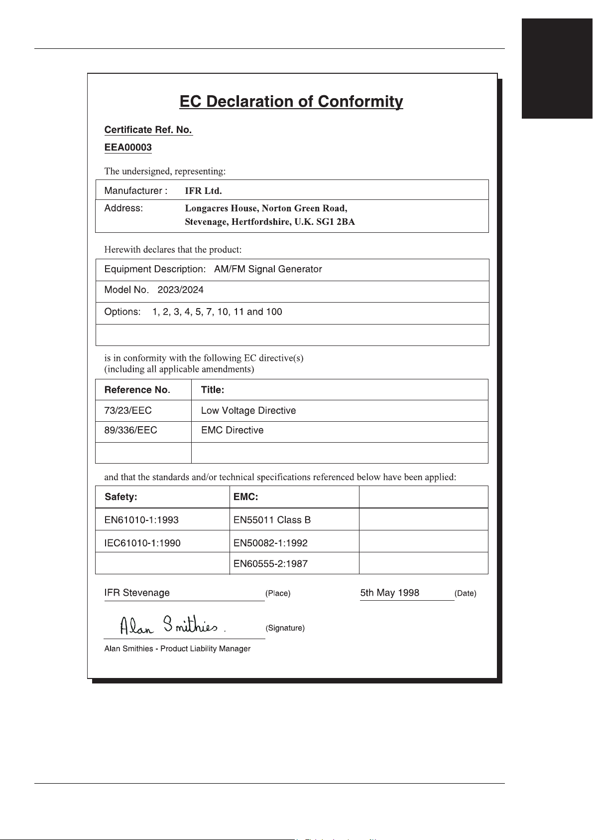
Patent protection
The 2023 and 2024 Signal Generators are protected by the following patents:
EP 0322139
GB 2214012
US 4870384
EP 0125790
GB 2140232
US 4609881
Preface
iv 46882-225U
Page 6
Precautions
These terms have specific meanings in this manual:
WARNING
information to prevent personal injury.
information to prevent damage to the equipment.
important general information.
Hazard symbols
The meaning of hazard symbols appearing on the equipment is as follows:
Symbol Description
!
General hazard
Dangerous voltage
Toxic hazard
General conditions of use
This product is designed and tested to comply with the requirements of IEC/EN61010-1 ‘Safety
requirements for electrical equipment for measurement, control and laboratory use’, for Class I,
portable equipment and is for use in a pollution degree 2 environment. The equipment is designed
to operate from an installation category I and II supply.
Equipment should be protected from the ingress of liquids and precipitation such as rain, snow,
etc. When moving the equipment from a cold to a hot environment, it is important to allow the
temperature of the equipment to stabilise before it is connected to the supply to avoid condensation
forming. The equipment must only be operated within the environmental conditions specified in
Chapter 1 ‘Performance data’ in the Operating manual, otherwise the protection provided by the
equipment may be impaired.
This product is not approved for use in hazardous atmospheres or medical applications. If the
equipment is to be used in a safety-related application, e.g. avionics or military applications, the
suitability of the product must be assessed and approved for use by a competent person.
WARNING
!
Electrical hazards (AC supply voltage)
This equipment conforms with IEC Safety Class I, meaning that it is provided with a protective
grounding lead. To maintain this protection the supply lead must always be connected to the
source of supply via a socket with a grounded contact.
Be aware that the supply filter contains capacitors that may remain charged after the equipment is
disconnected from the supply. Although the stored energy is within the approved safety
requirements, a slight shock may be felt if the plug pins are touched immediately after removal.
Do not remove covers, no user serviceable parts inside. See list of IFR Ltd International Service
Centres at rear of manual.
Fuses
Note that the internal supply fuse is in series with the live conductor of the supply lead. If
connection is made to a 2-pin unpolarized supply socket, it is possible for the fuse to become
Page 7
PRECAUTIONS
transposed to the neutral conductor, in which case, parts of the equipment could remain at supply
potential even after the fuse has ruptured.
WARNING
Fire hazard
!
WARNING
Toxic hazards
WARNING
Beryllia
Make sure that only fuses of the correct rating and type are used for replacement.
If an integrally fused plug is used on the supply lead, ensure that the fuse rating is commensurate
with the current requirements of this equipment. See under 'Performance Data' in Chapter 1 for
power requirements.
Some of the components used in this equipment may include resins and other materials which give
off toxic fumes if incinerated. Take appropriate precautions, therefore, in the disposal of these
items.
Beryllia (beryllium oxide) is used in the construction of some of the components in this
equipment. This material, if incorrectly handled, could cause a danger to health - refer to the
Maintenance part of the Service Manual for safe handling precautions.
WARNING
Beryllium copper
Some mechanical components within this instrument are manufactured from beryllium copper.
This is an alloy with a beryllium content of approximately 5%. It represents no risk in normal use.
The material should not be machined, welded or subjected to any process where heat is involved.
It must be disposed of as “special waste”.
It must NOT be disposed of by incineration.
WARNING
!
Tilt facility
When the instrument is in the tilt position, it is advisable, for stability reaso ns, not to stack other
instruments on top of it.
Static sensitive components
This equipment contains static sensitive components which may be damaged by handling - refer to
the Maintenance part of the Service Manual for handling precautions.
vi 46882-225U
Page 8

PRECAUTIONS
Précautions
Les termes suivants ont, dans ce manuel, des significations particulières:
WARNING
contient des informations pour éviter toute blessure au personnel.
contient des informations pour éviter les dommages aux équipements.
contient d'importantes informations d'ordre général.
Symboles Signalant Un Risque
La signification des symboles liés à cet équipement est la suivante:
Symbole Nature du risque
!
Risques généraux
Tension dangereuse
Danger produits toxiques
Conditions générales d’utilisation
Ce produit a été conçu et testé pour être conforme aux exigences des normes CEI/EN61010-1
“Règles de sécurité pour appareils électriques de mesurage, de régulation et de laboratoire”, pour
des équipements Classe I, portables et pour une utilisation dans un environnement de pollution de
niveau 2. Cet équipement est conçu pour fonctionner à partir d’une alimentation de catégorie I et
II.
Cet équipement doit être protégé de l’introduction de liquides ainsi que des précipitations d’eau,
de neige, etc... Lorsqu’on transporte cet équipement d’un environnement chaud vers un
environnement froid, il est important de laisser l’équipement se stabiliser en température avant de
le connecter à une alimentation afin d’éviter toute formation de condensation. L'appareil doit être
utilisé uniquement dans le cadre des conditions d'environnement spécifiées au chapitre 1
"Performance data" du manuel d'utilisation, toute autre utilisation peut endommager les systèmes
de protection.
Ce produit n’est pas garanti pour fonctionner dans des atmosphères dangereuses ou pour un usage
médical. Si l'équipement doit être utilisé pour des applications en relation avec la sécurité, par
exemple des applications militaires ou aéronautiques, la compatibilité du produit doit être établie
et approuvée par une personne compétente.
WARNING
Sécurité électrique (tension d’alimentation alternative)
!
46882-225U vii
Cet appareil est protégé conformément à la norme CEI de sécurité Classe 1, c’est-à-dire que sa
prise secteur comporte un fil de protection à la terre. Pour maintenir cette protection, le câble
d’alimentation doit toujours être branché à la source d’alimentation par l’intermédiaire d’une prise
comportant une borne de terre.
Notez que les filtres d’alimentation contiennent des condensateurs qui peuvent encore être chargés
lorsque l’appareil est débranché. Bien que l’énergie contenue soit conforme aux exigences de
sécurité, il est possible de ressentir un léger choc si l’on touche les bornes sitôt après
débranchement.
Ne pas enlever les capots, aucune pièce réparable ne se trouve à l'intérieur. Contacter un des
Centres de Maintenance Internationaux de IFR Ltd dans la liste jointe à la fin du manuel.
Page 9
PRECAUTIONS
Fusibles
Notez que le fusible d’alimentation interne est en série avec la phase du câble d’alimentation. Si la
prise d’alimentation comporte deux bornes non polarisées, il est possible de connecter le fusible au
neutre. Dans ce cas, certaines parties de l’appareil peuvent rester à un certain potentiel même
après coupure du fusible.
WARNING
Risque lie au feu
!
WARNING
WARNING
Lors du remplacement des fusibles vérifiez l'exactitude de leur type et de leur valeur.
Si le cable d'alimentation comporte une prise avec fusible intégré, assurez vous que sa valeur est
compatible avec les besoins en courant de l'appareil. Pour la consommation, reportez-vous au
chapitre 1 "Spécifications".
Danger produits toxiques
Certains composants utilisés dans cet appareil peuvent contenir des résines et d'autres matières qui
dégagent des fumées toxiques lors de leur incinération. Les précautions d'usages doivent donc être
prises lorsqu'on se débarrasse de ce type de composant.
Le Beryllia
Le Beryllia (oxyde de Beryllium) entre dans la composition de certains composants de cet
appareil. Cette matière peut représenter un danger pour la santé s'il elle n'est pas manipulée de
façon correcte - se référer à la partie "Maintenance" du "Manuel de Maintenance" pour les
précautions de manipulation.
WARNING
Bronze au béryllium
Dans cet équipement,certaines pièces mécaniques sont à base de bronze au béryllium. Il s'agit d'un
alliage dans lequel le pourcentage de béryllium ne dépasse pas 5%. Il ne présente aucun danger en
utilisation normale.
Toutefois, cet alliage ne doit pas être travaillé, soudé ou soumis à un processus qui implique
l'utilisation d'une source de chaleur.
En cas de destruction, il sera entreposé dans un container spécial. IL ne devra pas être détruit par
incinération.
WARNING
!
Position inclinée
Lorsque l'appareil est dans une position inclinée, il est recommandé, pour des raisons des stabilité,
de ne pas y empiler d'autres appareils.
viii 46882-225U
Page 10
Vorsichtsmaßnahmen
Diese Hinweise haben eine bestimmte Bedeutung in diesem Handbuch:
PRECAUTIONS
WARNING
dienen zur Vermeidung von Verletzungsrisiken.
dienen dem Schutz der Geräte.
enthalten wichtige Informationen.
Gefahrensymbole
Die Gefahrensymbole auf den Geräten sind wie folgt:
Symbol Gefahrenart
!
Allgemeine Gefahr
Gefährliche Spannung
Warnung vor giftigen Substanzen
Allgemeine Hinweise zur Verwendung
Dieses Produkt wurde entsprechend den Anforderungen von IEC/EN61010-1
“Sicherheitsanforderungen für elektrische Ausrüstung für Meßaufgaben, Steuerung und
Laborbedarf”, Klasse I, transportabel zur Verwendung in einer Grad 2 verunreinigten Umgebung,
entwickelt und getestet. Dieses Gerät ist für Netzversorgung Klasse I und II zugelassen.
Das Gerät sollte vor dem Eindringen von Flüssigkeiten sowie vor Regen, Schnee etc. geschützt
werden. Bei Standortänderung von kalter in wärmere Umgebung sollte das Gerät wegen der
Kondensation erst nach Anpassung an die wärmere Umgebung mit dem Netz verbunden werden.
Das Gerät darf nur in Umgebungsbedingungen wie in Kapitel 1 "Leistungsdaten (Performance
data)" der Bedienungsanleitung beschrieben, betrieben werden; ansonsten wird der vom Gerät
vorgesehene Schutz des Anwenders beeinträchtigt.
Dieses Produkt ist nicht für den Einsatz in gefährlicher Umgebung (z.B. Ex-Bereich) und für
medizinische Anwendungen geprüft. Sollte das Gerät für den Einsatz in sicherheitsrelevanten
Anwendungen wie z.B. im Flugverkehr oder bei militaerischen Anwendungen vorgesehen sein, so
ist dieser von einer für diesen Bereich zuständigen Person zu beurteilen und genehmigen.
WARNING
Elektrische Schläge (Wechselspannungsversorgung)
!
46882-225U ix
Das Gerät entspricht IEC Sicherheitsklasse 1 mit einem Schutzleiter nach Erde. Das Netzkabel
muß stets an eine Steckdose mit Erdkontakt angeschlossen werden.
Filterkondensatoren in der internen Spannungsversorgung können auch nach Unterbrechung der
Spannungszuführung noch geladen sein. Obwohl die darin gespeicherte Energie innerhalb der
Sicherheitsmargen liegt, kann ein leichter Spannungsschlag bei Berührung kurz nach der
Unterbrechung erfolgen.
Entfernen Sie keine Gehäuseabdeckungen, es befinden sich keine austauschbaren Teile im Gerät.
Eine Liste der IFR Servicestellen finden Sie auf der Rückseite des Handbuches.
Page 11
PRECAUTIONS
Sicherungen
Die interne Sicherung in der Spannungszuführung ist in Reihe mit der spannungsführenden
Zuleitung geschaltet. Bei Verbindung mit einer zweiadrigen, nicht gepolten Steckdose kann die
Sicherung in der Masseleitung liegen, so daß auch bei geschmolzener Sicherung Geräteteile immer
noch auf Spannungspotential sind.
WARNING
Feuergefahr
!
WARNING
WARNING
Warnung vor giftigen Substanzen
Beryllium Oxid
Es dürfen nur Ersatzsicherungen vom gleichen Typ mit den korrekten Spezifikationen
entsprechend der Stromaufnahme des Gerätes verwendet werden. Siehe hierzu die Leistungsdaten
(Performance Data) in Kapitel 1.
In einigen Bauelementen dieses Geräts können Epoxyharze oder andere Materialien enthalten sein,
die im Brandfall giftige Gase erzeugen. Bei der Entsorgung müssen deshalb entsprechende
Vorsichtsmaßnahmen getroffen werden.
Beryllium Oxid wird in einigen Bauelementen verwendet.
Bei inkorrekter Handhabung kann dieses Material Gesundheitsschäden verursachen. Siehe hierzu
die Hinweise zur Handhabung im Service-Handbuch.
WARNING
Beryllium Kupfer
In diesem Gerät sind einige mechanische Komponenten aus Berylium Kupfer gefertigt. Dies ist
eine Verbindung welche aus einem Berylliumanteil von ca. 5 % besteht. Bei normaler
Verwendung besteht kein Gesundheitsrisiko.
Das Metall darf nicht bearbeitet, geschweißt oder sonstiger Wärmebehandlung ausgesetzt werden.
Es muß als Sondermüll entsorgt werden.
Es darf nicht durch Verbrennung entsorgt werden.
WARNING
!
Schrägstellung
Bei Schrägstellung des Geräts sollten aus Stabilitätsgründen keine anderen Geräte darauf gestellt
werden.
x 46882-225U
Page 12
Precauzioni
Questi termini vengono utilizzati in questo manuale con significati specifici:
PRECAUTIONS
WARNING
riportano informazioni atte ad evitare possibili pericoli alla persona.
riportano informazioni per evitare possibili pericoli all'apparecchiatura.
riportano importanti informazioni di carattere generale.
Simboli di pericolo
Significato dei simboli di pericolo utilizzati nell'apparato:
Simbolo
Tipo di pericolo
!
Pericolo generico
Tensione pericolosa
Pericolo sostanze tossiche
Condizioni generali d’uso
Questo prodotto è stato progettato e collaudato per rispondere ai requisiti della direttiva
IEC/EN61010-1 ‘Safety requirements for electrical equipment for measurement, control and
laboratory use’ per apparati di classe I, trasportabili e per l’uso in un ambiente inquinato di grado
2. L’apparato è stato progettato per essere alimentato da un alimentatore di categoria I e II.
Lo strumento deve essere protetto dal possibile ingresso di liquidi quali, ad es., acqua, pioggia,
neve, ecc. Qualora lo strumento venga portato da un ambiente freddo ad uno caldo, è importante
lasciare che la temperatura all’interno dello strumento si stabilizzi prima di alimentarlo per evitare
formazione di condense. Lo strumento deve essere utilizzato esclusivamente nelle condizioni
ambientali descritte nel capitolo 1 ‘Performance data’ del manuale operativo, in caso contrario le
protezioni previste nello strumento potrebbero risultare non sufficienti.
Questo prodotto non è stato approvato per essere usato in ambienti pericolosi o applicazioni
medicali. Se lo strumento deve essere usato per applicazioni particolari collegate alla sicurezza
(per esempio applicazioni militari o avioniche), occorre che una persona o un istituto competente
ne certifichi l'uso.
WARNING
Pericoli da elettricità (alimentazione c.a.)
!
46882-225U xi
Quest ’apparato è provvisto del collegamento di protezione di terra e rispetta le norme di sicurezza
IEC, classe 1. Per mantenere questa protezione è necessario che il cavo, la spina e la presa
d’alimentazione siano tutti provvisti di terra.
Il circuito d’alimentazione contiene dei filtri i cui condensatori possono restare carichi anche dopo
aver rimosso l’alimentazione. Sebbene l’energia immagazzinata è entro i limiti di sicurezza,
purtuttavia una leggera scossa può essere avvertita toccando i capi della spina subito dopo averla
rimossa.
Non rimuovere i coperchi, utilizzare solo parti di scorta originali. Vedi elenco internazionale dei
Centri di Assistenza in fondo al manuale.
Page 13
PRECAUTIONS
Fusibili
Notare che un fusibile è posto sul filo caldo del cavo di alimentazione. Qualora l’alimentazione
avvenga tramite due poli non polarizzati, è possibile che il fusibile vada a protezione del neutro
per cui anche in caso di una sua rottura, l’apparato potrebbe restare sotto tensione.
WARNING
Pericolo d'incendio
!
WARNING
WARNING
Assicurarsi che, in caso di sostituzione, vengano utilizzati solo fusibili della portata e del tipo
prescritti.
Se viene usata una spina con fusibili, assicurarsi che questi siano di portata adeguata ai requisiti di
alimentazione richiesti dallo strumento. Tali requisiti sono riportati nel cap. 1 "Performance data".
Pericolo sostanze tossiche
Alcuni dei componenti usati in questo strumento possono contenere resine o altri materiali che, se
bruciati, possono emettere fumi tossici. Prendere quindi le opportune precauzioni nell'uso di tali
parti.
Berillio
Berillio (ossido di berillio) è utilizzato nella costruzione di alcuni componenti di quest'apparato.
Questo materiale, se maneggiato non correttamente, può causare danni alla salute. Far riferimento
ai capitoli di manutenzione del Manuale di Servizio per le precauzioni richieste.
WARNING
Rame berillio
Alcuni componenti meccanici in questo strumento sono realizzati in rame berillio. Si tratta di una
lega con contenuto di berillio di circa il 5%, che non presenta alcun rischio in usi normali.
Questo materiale non deve essere lavorato, saldato o subire qualsiasi processo che coinvolge alte
temperature.
Deve essere eliminato come "rifiuto speciale". Non deve essere eliminato tramite "inceneritore".
WARNING
!
Posizionamento inclinato
Quando lo strumento è in posizione inclinata è raccomandato, per motivi di stabilità, non
sovrapporre altri strumenti.
xii 46882-225U
Page 14

Precauciones
Estos términos tienen significados específicos en este manual:
PRECAUTIONS
WARNING
contienen información referente a prevención de daños personales.
contienen información referente a prevención de daños en equipos.
contienen información general importante.
Símbolos de peligro
Los significados de los símbolos de peligro que aparecen en los equipos son los siguientes:
Símbolo
Naturaleza del peligro
!
Peligro general
Voltaje peligroso
Aviso de toxicidad
Condiciones generales de uso
Este producto ha sido diseñado y probado para cumplir los requerimientos de la normativa
IEC/EN61010-1 “Requerimientos de la normativa para equipos eléctricos de medida, control y uso
en laboratorio”, para equipos clase I, portátiles y para uso en un ambiente con un grado de
contaminación 2. El equipo ha sido diseñado para funcionar sobre una instalación de alimentación
de categorías I y II.
Debe protegerse el equipo de la entrada de líquidos y precipitaciones como nieve, lluvia, etc.
Cuando se traslada el equipo de entorno frío a un entorno caliente, es importante aguardar la
estabilización el equipo para evitar la condensación. Sólo debe utilizarse el aparato en las
condiciones ambientales especificadas en el capítulo 1 “Especificaciones” o “Performance data”
del Manual de Instrucciones/Manual de Operación, en caso contrario la propia protección del
equipo puede resultar dañada.
Este producto no ha sido aprobado para su utilización en entornos peligrosos o en aplicaciones
médicas. Si se va a utilizar el equipo en una aplicación con implicaciones en cuanto a seguridad,
como por ejemplo aplicaciones de aviónica o militares, es preciso que un experto competente en
materia de seguridad apruebe su uso.
WARNING
Nivel peligroso de electricidad (tensión de red)
!
46882-225U xiii
Este equipo cumple las normas IEC Seguridad Clase 1, lo que significa que va provisto de un
cable de protección de masa. Para mantener esta protección, el cable de alimentación de red debe
de conectarse siempre a una clavija con terminal de masa.
Tenga en cuenta que el filtro de red contiene condensadores que pueden almacenar carga una vez
desconectado el equipo. Aunque la energía almacenada está dentro de los requisitos de seguridad,
pudiera sentirse una ligera descarga al tocar la clavija de alimentación inmediatamente después de
su desconexión de red.
No quitar las tapas, en el interior no existen piezas reemplazables por el usuario. Vea la lista de
Centros de Servicios Internacionales en la parte trasera del manual.
Page 15
PRECAUTIONS
Fusibles
Se hace notar que el fusible de alimentación interno está enserie con el activo del cable de
alimentación a red. Si la clavija de alimentación de red cuenta con sólo dos terminales sin
polaridad, el fusible puede pasar a estar en serie con el neutro, en cuyo caso existen partes del
equipo que permanecerían a tensión de red incluso después de que el fusible haya fundido.
WARNING
Peligro de incendio
!
WARNING
WARNING
Asegúrese de utilizar sólo fusibles del tipo y valores especificados como recuesto.
Si se utiliza una clavija con fusible incorporado, aseg úrese de que los valores del fusible
corresponden a los requeridos por el equipo. Ver sección de especificaciones del capítulo 1 para
comprobar los requisitos de alimentación.
Aviso de toxicidad
Alguno de los componentes utilizados en este equipo pudieran incluir resinas u otro tipo de
materiales que al arder produjeran sustancias tóxicas, Por tanto, tome las debidas precauciones en
la manipulación de esas piezas.
Berilio
Berilio (óxido de berilio) Este material es utilizado en la fabricación de alguno de los componentes
de este equipo.
Si se manipulase incorrectamente podria causar daños a la salud - En la sección de mantenimiento
y reparación encontrará normas de manejo de seguridad.
WARNING
Berilio-cobre
Algunos componentes mecánicos contenidos en este instrumento incorporan berilio-cobre en su
proceso de fabricación. Se trata de una aleación con un contenido aproximado de berilio del 5%,
lo que no representa ningún riesgo durante su uso normal.
El material no debe ser manipulado, soldado, ni sometido a ningún proceso que implique la
aplicación de calor.
Para su eliminación debe tratarse como un "residuo especial". El material NO DEBE eliminarse
mediante incineración.
WARNING
!
Tener en cuenta con el equipo inclinado
Si utiliza el equipo en posición inclinada, se recomienda, por razones de estabilidad, no apilar
otros equipos encima de él.
xiv 46882-225U
Page 16

Chapter 1
Contents
GENERAL INFORMATION
Introduction....................................................................................................................................1-2
Main features..................................................................................................................................1-2
Operation
Display
Frequency selection
Output
Calibration
odulation..............................................................................................................................1-3
M
Increm
Frequency sweep
Mem
Program
Calibration data
Perform
Versions, options and accessories
.................................................................................................................................1-2
....................................................................................................................................1-2
.................................................................................................................1-2
.....................................................................................................................................1-2
...............................................................................................................................1-3
enting ...........................................................................................................................1-3
.....................................................................................................................1-3
ory...................................................................................................................................1-3
ming...........................................................................................................................1-4
.......................................................................................................................1-4
ance data............................................................................................................................1-5
..................................................................................................1-9
GENERAL
INFORMATION
46882-225U 1-1
Page 17

GENERAL INFORMATION
Introduction
The 2023 and 2024 are portable and lightweight synthesized signal generators covering the
frequency range 9 kHz to 1.2 GHz (2023) and 9 kHz to 2.4 GHz (2024). A dot matrix display
with a comprehensive set of utility menus allow flexibility of operation and ease of use. The RF
output can be amplitude, frequency, phase or pulse modulated. An internal programmable AF
source is capable of generating simultaneous two-tone modulation.
All parameters can be entered from a front panel keyboard and a rotary control can be used to
adjust most settings. Microprocessor control ensures that the instruments are flexible and easy to
use and allows programming by either the General Purpose Interface Bus (GPIB) or by RS-232.
The GPIB is designed to IEEE Standard 488.2. The interfaces allow remote control of all
functions except the supply switch, and allow the instruments to be used either manually or as part
of a fully automated test system.
Main features
Operation
Selection of parameters on the screen may involve one or more of the numeric, hard or menu
selection keys or the rotary control knob. Parameters may be set to specific values by numeric key
entry, while values may be varied in steps of any size using the DOWN/UP keys or altered by
moving the control knob, set to a particular sensitivity.
Display
The display is a dot matrix liquid crystal panel, with backlighting. Display contrast may be varied
to accommodate differing lighting conditions and the setting saved in memory. A graphical
display test is available to the user.
Frequency selection
Carrier frequency is either selected directly via the keyboard or remotely via the interfaces.
Frequency resolution is 1 Hz across the band. A series of carrier frequencies can be stored in nonvolatile memory for recall when required.
Output
RF output up to +13 dBm can be set by direct keyboard entry with a resolution of 0.1 dB over the
entire range. For instruments fitted with the high power option, RF output is increased to
+25 dBm. A carrier ON/OFF key is provided to completely disable the output.
A choice of level units is available to the user and provision is made for the conversion of units
(for example, dBm to μV) by a simple keypress.
An electronic trip protects the generator output against reverse power of up to 50 W. This prevents
damage to output circuits when RF or DC power is accidentally applied to the RF OUTPUT
connector.
To facilitate testing of receiver squelch systems, an attenuator hold function allows control of the
RF output without introducing RF level drop-outs from the step attenuator.
The RF output level can be offset by up to ±5.0 dB to compensate for cable or switching losses, or
standardize a group of instruments.
Maximum RF output level can be set so as to protect sensitive devices connected to the RF
OUTPUT socket.
1-2 46882-225U
Page 18

Spectral purity
Calibration
Modulation
With an SSB phase noise performance of typically -121 dBc/Hz at 20 kHz offset from a 1 GHz
carrier, these instruments can be used for both in-channel and adjacent channel receiver
measurements. Harmonically related signals and non-harmonics are typically better than -25 dBc
and -60 dBc respectively.
This instrument has a recommended two year calibration interval after which it should be returned
for recalibration (for addresses refer to 'Addresses' section at end of manual).
Comprehensive amplitude, frequency and phase modulations are available. Pulse modulation can
be applied to the carrier from an external pulse source. The instrument also accepts one or two
logic level inputs to produce a 2-level or 4-level FSK modulated output. An internal modulation
oscillator is provided, having a frequency range of 0.01 Hz to 20 kHz. The oscillator is capable of
generating one or two modulation tones simultaneously in one modulation channel. An
independent BNC input on the front panel allows external modulation signals to be combined with
the internal signal(s). These sources can be combined to give a number of modulation modes.
The pulse modulation can be used in combination with the other forms of modulation.
The frequency modulation range provides a 1 dB bandwidth of typically 100 kHz and provides
FM deviation up to a maximum of 100 kHz. AC or DC coupled FM can be selected. Phase
modulation is also available with a 9 kHz bandwidth up to a maximum of 10 radians.
Amplitude modulation with a 1 dB bandwidth of typically 30 kHz and with modulation depths of
up to 99.9% is available with a resolution of 0.1%. Pulse modulation is available as standard with
typical rise and fall times of less than 10 μs and 40 dB on/off ratio.
The external input voltage required for 100% modulation is 1 V RMS or, optionally, 1 V peak. To
accommodate other signal levels, Automatic Level Control (ALC) can be selected which provides
correctly calibrated modulation for inputs between 0.75 and 1.25 V RMS.
A MOD ON/OFF key simplifies the testing of signal to noise ratio.
An optional fast pulse modulator improves the rise/fall times to typically 10 ns.
GENERAL
INFORMATION
Incrementing
All major parameters can be incremented or decremented in step sizes entered via keyboard entry
or remotely. If no step size is entered for a parameter, the steps are preset to 1 kHz for carrier
frequency, 1 kHz for modulation oscillator, 1 kHz for FM deviation, 0.1% for AM depth, 0.01 rad
for ΦM and 1 dB for output level.
In addition, the rotary control knob can be used to vary the parameter with the sensitivity of the
knob being changed by means of the ×10 and ÷10 keys.
Frequency sweep
The sweep capability of the instrument allows comprehensive testing of systems. Sweeps may be
logarithmic or linear. Four parameters are used to specify sweep; start, stop, step size and time per
step and a percentage increment in the case of logarithmic sweep, all of which may be specified by
the user. The sweep can be paused at any time. During the sweep the RF level can be altered
using the rotary control. Sweep triggering can be single shot or continuous and can be initiated
directly or on the detection of a trigger. The triggering signal may either be programmed or from a
TTL signal applied to the rear panel TRIGGER input.
Memory
The instrument provides both non-volatile and volatile memory for storing instrument settings.
The non-volatile memory provides 100 instrument settings and 100 settings of carrier frequency
only. The volatile memory (RAM) also provides 100 instrument settings. Any one of the nonvolatile instrument settings can be selected as the power-up setting for the instrument.
46882-225U 1-3
Page 19

GENERAL INFORMATION
Memory cloning
The stored settings in one instrument can be easily transferred (without the use of a controller) to
another instrument using the RS-232 interface, or to several other instruments using the GPIB
interface.
Memory sequencing
A software facility allows sequences of stored instrument settings to be defined. The incrementing
facilities can then be used to cycle through the settings in manually operated test systems or be
operated via an external trigger.
Memory protection
To prevent accidental change of the contents of the stored settings, individual memories or ranges
of memories can be write-protected.
Programming
A GPIB interface is fitted so that all functions are controllable via the interface bus which is
designed to the IEEE Standard 488.2. The instrument can function both as talker and listener.
The instrument also has an RS-232 interface which uses the common GPIB command set. The
interfaces enable the instrument to be remotely controlled as well as being used to transfer settings
(cloning) from one instrument to another.
Calibration data
All alignment data is digitally derived. Realignment can be undertaken, without removing covers,
by protected front panel functions or via the GPIB interface.
1-4 46882-225U
Page 20

Performance data
Carrier frequency
Range: 9 kHz to 1.2 GHz (2023).
Resolution: 1 Hz.
Accuracy: Equal to the frequency standard accuracy.
RF output
Range: -140 dBm to +13 dBm.
Resolution: 0.1 dB.
Accuracy:
Attenuator hold: Selection of Attenuator Hold provides for uncalibrated level reduction of at least 10 dB
RF output connector:
VSWR: For output levels less than -5 dBm output VSWR is less than 1.3:1 for carrier frequencies
Output protection: Protected against the application of reverse power to the output connector for levels up
75 Ω calibration: The output level can be entered as the value after a 50/75 Ω external adapter.
9 kHz to 2.4 GHz (2024).
When AM is selected the maximum RF output level decreases linearly with increasing
AM depth to +7 dBm at 99.9% depth.
For output levels above -127 dBm and over a temperature range of 17 to 27°C:
±0.8 dB to 1.2 GHz;
±1.6 dB to 2.4 GHz.
Temperature coefficient <±0.02 dB/°C to 1.2 GHz, and <±0.04 dB/°C to 2.4 GHz.
without the mechanical attenuator operating.
50 Ω, type-N connector to MIL 390123D.
up to 1.2 GHz and less than 1.5:1 for carrier frequencies up to 2.4 GHz.
to 50 W from 50 Ω or 25 W from a source VSWR of 5:1. Protection circuit can be reset
from the front panel or via the GPIB/RS-232 interfaces.
GENERAL
INFORMATION
Spectral purity
Harmonics: Typically better than -30 dBc for RF levels up to +7 dBm.
Non-harmonics: Better than -70 dBc for carrier frequencies up to 1 GHz.
Residual FM (FM off): Less than 4.5 Hz RMS in a 300 Hz to 3.4 kHz unweighted bandwidth at a carrier
SSB phase noise: Better than -124 dBc/Hz at 20 kHz offset from a 470 MHz carrier.
RF leakage:
Modulation
Frequency modulation
Deviation range: 0 to 100 kHz.
Resolution: 3 digits or 1 Hz.
Bandwidth (1 dB): DC to 100 kHz (DC coupled),
Accuracy:
Carrier frequency Less than 1% of the set frequency deviation.
Typically better than -25 dBc for RF levels up to +13 dBm.
Better than -64 dBc for carrier frequencies above 1 GHz.
Better than -60 dBc for carrier frequencies above 2 GHz.
frequency of 1 GHz.
Residual FM (typical)
<1 Hz at 249 MHz
<2 Hz at 501 MHz
<3 Hz at 1001 MHz
<6 Hz at 2001 MHz
Typically -121 dBc/Hz at 20 kHz offset from a 1 GHz carrier.
Less than 0.5 μV at the carrier frequency into a two-turn 25 mm diameter loop 25 mm
from the surface of the signal generator.
FM, AM or phase modulation can be applied to the carrier from an internal or external
modulation source. The internal modulation source is capable of generating two
simultaneous signals into any one of the modulation channels. Internal and external
modulation can be simultaneously enabled to produce combined amplitude and
frequency (or phase) modulation. Pulse modulation can be applied to the carrier from an
external pulse source. The pulse modulation can be used in combination with the other
forms of modulation. 2 level or 4 level FSK modulation can be applied to the carrier
using data from an external source.
10 Hz to 100 kHz (AC coupled),
20 Hz to 100 kHz (AC coupled with ALC).
±5% at 1 kHz modulation rate.
46882-225U 1-5
Page 21

GENERAL INFORMATION
offset (DC coupled):
Distortion: Less than 1% at 1 kHz rate for deviations up to 100 kHz. Typically 0.3% at 1 kHz rate for
Group delay:
deviations up to 10 kHz.
Less than 5 μs to 100 kHz.
FSK
Modes: 2 level or 4 level FSK.
Data source: External data connected to 2FSK connector (2 level) or 2FSK and 4FSK connectors
Frequency shift:
Accuracy: As FM deviation accuracy.
Timing jitter:
Filter:
Phase modulation
Range: 0 to 10 radians.
Resolution: 3 digits or 0.01 radians.
Bandwidth (3 dB): 100 Hz to 10 kHz.
Accuracy:
Distortion: Less than 3% at 10 radians at 1 kHz.
Amplitude modulation (for carrier
frequencies <500 MHz, usable to
1.5 GHz)
Range: 0 to 99.9%.
Bandwidth (1 dB): DC to 30 kHz (DC coupled),
Resolution: 0.1%.
Accuracy:
Distortion: Less than 2.5% at 1 kHz rate for modulation depths up to 80%.
ΦM on AM:
Pulse modulation (for fast pulse
see Options 7 or 11 when fitted)
Carrier frequency range: 32 MHz to 2.4 GHz, usable to 10 MHz.
RF level range: Maximum guaranteed output is reduced to +8 dBm (+20 dBm or +14 dBm with high
RF level accuracy:
Input:
On-off ratio: Better than 40 dB,
Rise and fall time:
Overshoot: Less than 1 dB.
(4 level).
Settable up to ±100 kHz.
±3.2 μs
th
order Bessel, −3 dB at 20 kHz.
8
±5% at 1 kHz modulation rate.
Typically 0.5% for deviations up to 1 radian at 1 kHz.
10 Hz to 30 kHz (AC coupled),
20 Hz to 30 kHz (AC coupled with ALC).
±5% of set depth at 1 kHz rate at +17°C to 27°C ambient temperature.
Temperature coefficient <0.02% per °C.
Less than 1.5% at 1 kHz rate for modulation depths up to 30%.
Typically 0.1 radians at 30% depth at 470 MHz.
power option) when pulse modulation is selected.
Maximum additional uncertainty is ±0.5 dB.
Rear panel BNC connector with an input impedance of 10 kΩ nominal. A logical '1' (5 V) turns
the carrier on, a logical '0' (0 V) turns the carrier off. Maximum safe input is ±15 V.
better than 45 dB below 1.2 GHz.
Less than 10 μs.
Modulation oscillator
Frequency range: 0.01 Hz to 20 kHz.
Resolution: 0.01 Hz to 100 Hz,
Distortion: Less than 0.1% at 1 kHz.
Sine wave frequency response: Typically 1 dB DC to 20 kHz.
The internal modulation oscillator is capable of generating one or two modulation tones
simultaneously in one modulation channel.
0.1 Hz to 1 kHz,
1 Hz to 20 kHz.
1-6 46882-225U
Page 22

Waveforms: Sine (to 20 kHz),
Output: The modulation oscillator signal is available on a front panel BNC connector at a nominal
External modulation input
Input level: 1 V RMS (1.414 V peak) sine wave for set deviation. Input sensitivity may be optionally
Input impedance:
Modulation ALC:
Sweep mode
Frequency standard
Internal standard: 10 MHz TCXO.
Aging rate:
Temperature stability:
External standard:
Calibration interval
Remote control
GPIB: All functions except the supply switch are remotely programmable.
Capabilities: Complies with the following subsets as defined in IEEE Std 488.1: SH1, AH1, T6, TE0,
RS-232: All functions except the supply switch are remotely programmable.
Connector: 9-way male D-type.
Baud rate: 300 to 9600 bit/s.
Handshake: Hardware: DTR, RTS, CTS and DSR.
Electrical: Interface to EIA-232-D.
triangle or square wave (to 3 kHz).
Square wave jitter <6.4 μs on any edge.
level of 2 V RMS EMF from a 600 Ω source impedance.
A front panel external modulation input is provided.
specified for 1 V peak (Option 10). Maximum safe input is ±15 V.
100 kΩ nominal.
Levels the applied external modulation over the range 0.75 to 1.25 V RMS. High and
low indicators in display indicate when the input is outside levelling range.
A carrier frequency sweep mode is provided. The sweep is defined by entry of the start,
stop and frequency step size. The sweep step size may be specified linearly or
logarithmically. The step time can be set from 20 ms to 10 s per step. A trigger input on
the rear panel may be used to trigger a step or the complete sweep. Sweep can be set
to continuous.
The carrier frequency and internal modulation frequency are synthesized from either an
internal reference oscillator or an external reference.
Less than ±1 in 106 per year.
Better than ±5 in 107 over the temperature range 0 to 55°C.
Input: Requires an input of 220 mV RMS to 1.8 V RMS into 1 kΩ on rear panel BNC
connector. Input frequency can be 1 MHz or 10 MHz.
Output: Rear panel BNC socket provides an output of 10 MHz at a nominal level of 2 V
pk-pk into 50 Ω.
Recommended 2 years. Realignment can be accomplished by GPIB control or from the
front panel. There are no mechanical adjustments required for realignment.
L4, LE0, SR1, PP0, DC1, DT1, C0, E2.
Software: XON and XOFF.
GENERAL
INFORMATION
Electromagnetic compatibility
Safety
Rated range of use (over which full
specification is met)
Conditions of storage and
transport
Power requirements
Dimensions and weight Height Width Depth Weight
Conforms to the protection requirements of Council Directive 89/336/EEC.
Complies with the limits specified in the following standards:
EN55011 Class B CISPR 11
EN50082-1 IEC 1000-4-2,-3,-4
EN61000-3-2 IEC 1000-3-2
This instrument is designed to comply with the requirements of EN61010-1/IEC1010-1,
for Class 1 portable equipment and is for use in a pollution degree 2 environment. The
equipment is designed to operate from an installation category 1 and 2 supply.
Temperature: 0 to +55°C.
Humidity: Up to 93% at 40°C.
Altitude: Up to 3050 m (10,000 ft).
Temperature: -40°C to +71°C.
Humidity
Altitude: Up to 4600 m (15,000 ft).
47 to 63 Hz at 90 to 132 V, or 188 to 264 V at 175 VA maximum.
107 mm 419 mm 440 mm <8 kg
4.2 in 16.5 in 17.3 in <17.6 lb
: Up to 95% at 40°C.
46882-225U 1-7
Page 23

GENERAL INFORMATION
Options
Option 1: No attenuator
Omits the internal step attenuator. Specification as standard instrument with the following
exceptions:
RF output range: -2 dBm to +15 dBm. When AM is selected the maximum output level reduces linearly
RF level accuracy: As standard instrument for levels between -2 dBm and +15 dBm.
Pulse modulation: Not available.
Reverse power protection:
Option 2: DC operation
Allows for operation from an external DC power source in addition to an AC power source.
Specification as standard instrument with the following additions:
DC supply range: 11 to 32 V.
DC consumption: 70 W with Option 3 not fitted.
AC supply frequency 47 to 440 Hz at 90 to 132 V,
with AM depth to +9 dBm at maximum AM depth.
Reverse power protection is not provided.
18 to 32 V when acting as backup to AC supply.
47 to 63 Hz at 188 to 264 V.
Option 3: High power
Increases maximum output from the normal +13 dBm. Specification as standard instrument with
the following exceptions:
RF output range: -140 dBm to +25 dBm (output power above +19 dBm is uncalibrated for carrier
RF level accuracy:
Harmonics: Typically better than -25 dBc for levels 6 dB below the maximum specified output.
frequencies above 1.2 GHz).
Maximum output is reduced by 5 dB when pulse modulation is selected and/or by up to
6 dB dependant upon set AM depth.
Over a temperature range 17°C to 27°C:
±1 dB up to 1.2 GHz,
±2 dB up to 2.4 GHz.
Temperature coefficient <±0.02 dB/°C to 1.2 GHz, and <±0.04 dB/°C to 2.4 GHz.
Option 4: High stability frequency standard
Replaces the internal TCXO with a high stability OCXO. Specification as standard instrument
with the following exceptions:
Aging rate:
Temperature stability:
Warm-up time:
<±2.5 in 107 per year, <±5 in 109 per day after 2 months continuous use.
Better than ±5 in 108 over the temperature range 0 to 50°C.
Within 2 in 107 of final frequency 10 minutes after switch on at a temperature of 20°C.
Option 5: Rear panel connectors
The front panel connectors RF OUTPUT, LF OUTPUT and EXT MOD INPUT are relocated on
the rear panel for rack mounted operation.
Option 7: See Annex B.
Option 10:
External modulaton input
Level 1 V peak (0.707 V RMS) sine wave for set deviation. Maximum safe input is
1-8 46882-225U
1 V peak mod input.
The external modulation input level is changed to 1 V peak sine wave for set deviation.
±15 V.
Page 24

Option 11: See Annex C.
Option 100:
See Annex A.
Versions, options and accessories
When ordering please quote the full ordering number information.
Ordering numbers Versions
2023 9 kHz to 1.2 GHz Signal Generator.
9 kHz to 2.4 GHz Signal Generator.
2024
Options
Option 1 No attenuator.
Option 2 DC operation.
Option 3 High power.
Option 4 High stability frequency standard.
Option 5 Rear panel connectors.
Option 7 Fast pulse modulation.
Option 10 1 V peak mod input.
Option 11 Fast pulse and high power.
Option 100 Internal pulse generator.
Supplied accessories
− AC power supply lead (see ‘Power cords’, Chap. 2).
46882-225U Operating manual (this manual).
43130-119U DC supply lead (supplied with Option 2 only).
Optional accessories
54311-208Z 50/75 Ω adapter.
46880-068C Service manual.
46884-792D Rack bracket kit containing rack mounting brackets only.
46662-601J Transit case.
46662-602F Carrying case.
46884-650F RS-232 cable, 9-way female to 9-way female, 1.5 m.
46883-408K IEEE/IEC adapter block for GPIB socket.
43129-189U GPIB lead assembly.
59999-524N TEM cell.
GENERAL
INFORMATION
46882-225U 1-9
Page 25

Page 26
GENERAL
INFORMATION
46882-225U 1-11
Page 27

Contents
Chapter 2
INSTALLATION
Initial visual inspection ..................................................................................................................2-2
Installation requirements................................................................................................................2-2
Mounting arrangem
Ventilation
Power cords
Goods-in checks
Instrum
AC operation
DC operation (Option 2)
General purpose interface bus (GPIB)
IEEE to IEC conversion
RS-232 interface
Rack m
Routine m
Cleaning
Cleaning the LCD window
Putting into storage
ent operating position.........................................................................................................2-4
Connecting to supply
AC fuse
Internal fuse
Connecting to supply
DC fuse
DC supply
GPIB cable connection
GPIB connector contact assignm
Interface bus connection
RS-232 connector
ounting ...............................................................................................................................2-7
Safety testing and inspection
...............................................................................................................................2-2
....................................................................................................................................2-2
..................................................................................................................................2-5
...................................................................................................................................2-5
...................................................................................................................................2-5
cable......................................................................................................................2-5
aintenance......................................................................................................................2-7
.........................................................................................................................................2-9
ents ..........................................................................................................2-2
.............................................................................................................................2-2
..............................................................................................................2-5
............................................................................................................................2-5
................................................................................................................2-5
..............................................................................................................2-5
...........................................................................................2-5
............................................................................................................2-6
ents......................................................................................2-6
.................................................................................................................2-6
.........................................................................................................2-6
.............................................................................................................................2-7
....................................................................................................................2-7
...................................................................................................2-7
.............................................................................................................2-9
........................................................................................................................2-9
INSTALLATION
List of figures
Fig. 2-1 DC INPUT socket showing connector polarity (viewed from rear of instrument).........2-5
Fig. 2-2 GPIB connector contact assignments (viewed from rear of instrument).........................2-6
Fig. 2-3 IEEE to IEC conversion
Fig. 2-4 RS-232 connector contact assignm
46882-225U 2-1
..................................................................................................2-6
ents (viewed from rear of instrument)......................2-7
Page 28

INSTALLATION
WARNING
Initial visual inspection
After unpacking the instrument, inspect the shipping container and its cushioning material for
signs of stress or damage. If damage is identified, retain the packing material for examination by
the carrier in the event that a claim is made. Examine the instrument for signs of damage; do not
connect the instrument to a supply when damage is present, internal electrical damage could result
in shock if the instrument is turned on.
Installation requirements
Mounting arrangements
Excessive temperatures may affect the performance of the instrument. Completely remove the
plastic cover, if one is supplied over the case, and avoid standing the instrument on or close to
other equipment which is hot.
Ventilation
This instrument is forced air cooled by a fan mounted on the rear panel. Air must be allowed to
circulate freely through the ventilator grills located on the side and underside of the instrument.
Before switching on the instrument, ensure that the fan outlet on the rear panel is not restricted
(i.e., clearance of at least 75 mm at the rear, 25 mm at each side, 15 mm on the underside). Failure
to provide to adequate clearances will increase internal temperatures and reduce the instrument
reliability, so its performance may not meet specification.
Power cords
Class I power cords (3-core)
General
When the equipment has to be plugged into a Class II (ungrounded) 2-terminal socket outlet, the
cable should either be fitted with a 3-pin Class I plug and used in conjunction with an adapter
incorporating a ground wire, or be fitted with a Class II plug with an integral ground wire. The
ground wire must be securely fastened to ground. Grounding one terminal on a 2-terminal socket
will not provide adequate protection.
In the event that a moulded plug has to be removed from a lead, it must be disposed of
immediately. A plug with bare flexible cords is hazardous if engaged in a live socket outlet.
Power cords with the following terminations are available from IFR Ltd. Please check with your
local sales office for availability.
This equipment is provided with a 3-wire (grounded) cordset which includes a moulded IEC 320
connector for connection to the equipment. The cable must be fitted with an approved plug which,
when plugged into an appropriate 3-terminal socket outlet, grounds the case of the equipment.
Failure to ground the equipment may expose the operator to hazardous voltage levels. Depending
upon the destination country, the colour coding of the wires will differ:-
2-2 46882-225U
Page 29
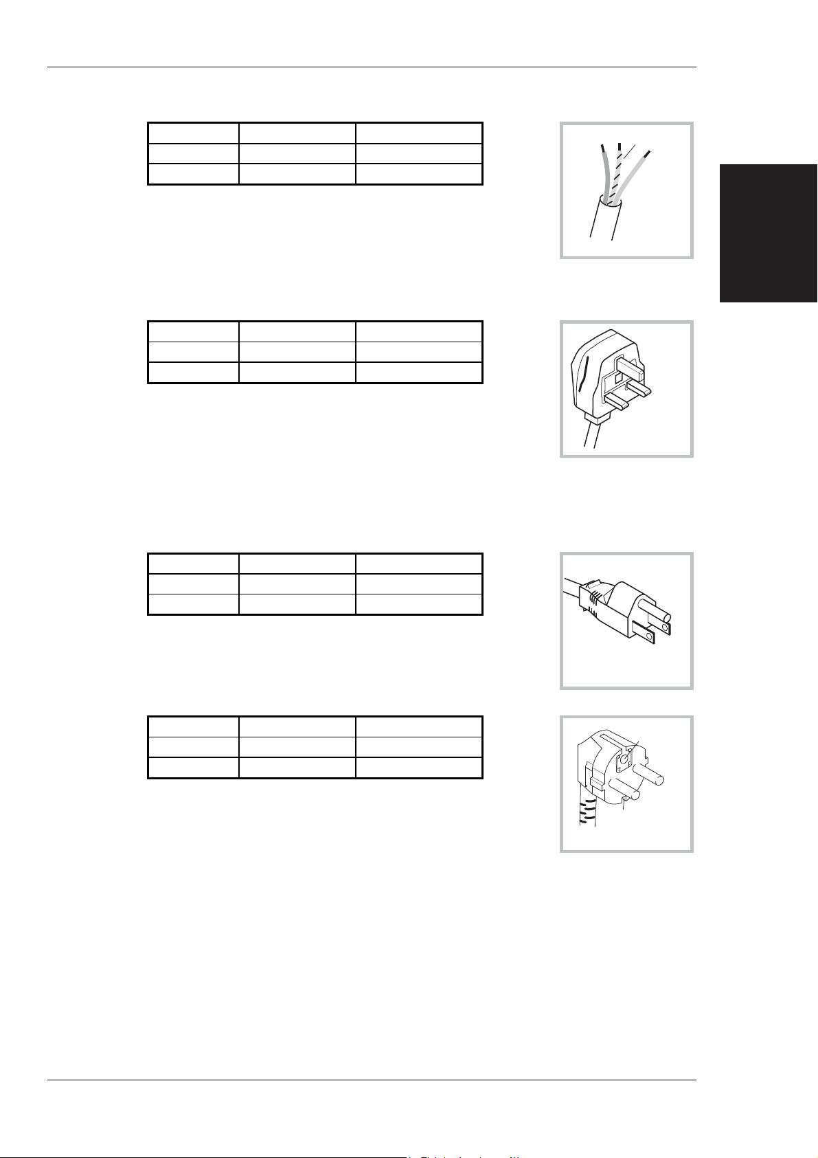
Wire ended
INSTALLATION
Country IEC 320 plug type IFR part number
GREEN/YELLOW
EARTH
Universal Straight through 23424-158
Universal Right angled 23424-159
BROWN
LIVE
BLUE
NEUTRAL
North America Harmonised
Line (Live) Black Brown
Neutral White Blue
Ground (Earth) Green Green/Yellow
HARMONISED-WIRE ENDED
C3509
INSTALLATION
British
Country IEC 320 plug type IFR part number
United Kingdom Straight through 23422-001
United Kingdom Right angled 23422-002
The UK lead is fitted with an ASTA approved moulded plug to BS
1363.
A replaceable 13 A fuse to BS 1362 is contained within the plug. This
fuse is only designed to protect the lead assembly. Never use the plug
with the detachable fuse cover omitted or if the cover is damaged.
The fuse(s) or circuit breaker to protect the equipment is fitted at the back of the equipment.
EARTH
NEUTRAL
LIVE
UNITED KINGDOM
C3510
North American
Country IEC 320 plug type IFR part number
North American Straight through 23422-004
North American Right angled 23422-005
The North American lead is fitted with a NEMA 5-15P (Canadian
CS22.2 No 42) plug and carries approvals from UL and CSA for use in
the USA and Canada.
Continental Europe
Country IEC 320 plug type IFR part number
Europe Straight through 23422-006
Europe Right angled 23422-007
The Continental European lead is fitted with a right angle IEC83
standard C4 plug (CEE 7/7) which allows it to be used in sockets with
either a male earth pin (standard C 3b) or side earth clips (standard
C 2b) the latter is commonly called the German ‘Schuko’ plug. In
common with other Schuko style plugs, the plug is not polarized when
fitted into a Schuko socket. The lead carries approvals for use in Austria, Belgium, Finland,
France, Germany, Holland, Italy, Norway and Sweden. Note that this plug will not fit Italian
standard CEI 23-16 outlets. The lead should not be used in Denmark given that the earth
connection will not be made.
NEUTRAL
U.S./CANADA/KOREA
EARTH
NEUTRAL
EARTH
CONTINENTAL
EUROPE
EARTH
LIVE
C3511
LIVE
C3512
Français
Le câble d'alimentation d'Europe Continentale est muni d'un connecteur mâle à angle droit type
CEI83, standard C4 (CEE 7/7), qui peut être utilisé dans une prise femelle à ergot de terre
(standard C 3b) ou à clips latéraux (standard C 2b), cette dernière étant communément appelée
prise “Schuko” allemande. De la même façon que les autres connecteurs de type Schuko, celui-ci
n'est pas polarisé lorsqu'il s'adapte à une prise femelle Schuko. Ce câble d'alimentation est
46882-225U 2-3
Page 30

INSTALLATION
Deutsch
Español
homologué en Allemagne, Autriche, Belgique, Finlande, France, Hollande, Italie, Norvège et
Suède. A noter que ce connecteur n'est pas compatible avec les prises de courant italiennes au
standard CEI 23-16. Ce câble ne doit pas être utilisé au Danemark à cause du défaut de connexion
de masse.
Das kontinentaleuropäische Netzkabel ist mit einem rechtwinkeligen Stecker nach IEC83 C4
(CEE7/7) Standard versehen, welcher sowohl in Steckdosen mit Erde-Stift (Standard C 3b) oder
seitlichen Erdeklemmen, im allgemeinen “Schukosteckdose” genannt, paßt. Üblicherweise ist der
Schukostecker bei Verwendung in Schukosteckdosen nicht gepolt. Dieses Netzkabel besitzt
Zulassung für Österreich, Belgien, Finnland, Frankreich, Deutschland, Holland, Italien, Norwegen
und Schweden.
Hinweis: Dieser Schukostecker paßt nicht in die italienischen Standardsteckdosen nach CEI 23-16
Norm. Dieses Netzkabel sollte nicht in Dänemark verwendet werden, da hier keine
Erdeverbindung hergestellt wird.
El cable de alimentación tipo Europeo Continental dispone de una clavija C4 normalizada IEC83
(CEE 7/7) que permite su utilización tanto en bases de enchufe con toma de tierra macho (tipo C
3b) o con toma de tierra mediante contactos laterales (tipo C 2b) que, en este último caso, suele
denominarse “Schuko”. Al igual que cualquier otra clavija tipo Schuko, las conexiones a red no
están polarizadas cuando se conectan a una base tipo Schuko. El cable lleva autorización para su
uso en Austria, Bélgica, Finlandia, Francia, Alemania, Holanda, Italia, Noruega y Suecia.
Observe que este cable no se adapta a la norma italiana CEI 23-16. El cable no debe utilizarse en
Dinamarca en el caso de no efectuarse conexión a tierra.
Italiano
I cavi d'alimentazione per l'Europa continentale vengono forniti terminati con una spina ad angolo
retto del tipo C4 secondo lo standard IEC83 (CEE 7/7) che può essere usato in prese in cui la terra
può essere fornita o tramite connettore maschio (C 3b) o tramite clips laterali (C 2b), quest'ultima
comunemente detta di tipo tedesca “Schuko”. Questa spina, quando collegata ad una presa
Schuko, non è polarizzata.
Il cavo può essere usato in Austria, Belgio, Finlandia, Francia, Germania, Olanda, Norvegia,
Svezia ed Italia. E' da notare che per l'Italia questo non risponde allo standard CEI 23-16.
Questa spina non dovrebbe invece essere usata in Danimarca in quanto non realizza il
collegamento di terra.
Goods-in checks
The following goods-in check verifies that the instrument is functioning correctly, but does not
verify conformance to the listed specification. To verify that the instrument conforms to the
specification given in Chapter 1, refer to Chapter 7, 'Acceptance testing'.
(1) Ensure that the correct fuse is fitted (accessible from the rear panel) and connect the
instrument to the supply.
(2) Switch on and check that a display is present.
(3) If the instrument appears to be completely dead, carry out the following :
Check that the mains power supply line is providing power to the instrument.
Check that the mains fuses have not blown.
Instrument operating position
For reasons of stability and ventilation the instrument must only be operated on its underside feet
(with or without the tilt stands).
2-4 46882-225U
Page 31

AC operation
Connecting to supply
Ensure that the AC supply is correctly connected to the POWER SUPPLY socket. For supplies in
the range 90 - 132 V and 188 - 264 V the PSU automatically selects the appropriate range. There
is no manual voltage range selection provided.
Note that for AC operation when Option 2: DC operation is fitted, the AC supply frequency range
is extended to 440 Hz within the AC supply range of 90 to 132 V.
AC fuse
For the AC voltage range of 90 to 264 V the fuse rating is 2 A-T (time lag). The AC fuse is a
cartridge type measuring 20 mm x 5 mm.
The fuse-holder is integral with the rear panel 3-pin supply plug. For access to change the fuse,
use a screwdriver to lever out the holder.
Internal fuse
Note that there is an additional, non-operator replaceable internal, fuse fitted in the switched mode
power supply (not applicable to instruments fitted with Option 2, DC operation, which have a
different power supply).
INSTALLATION
INSTALLATION
DC operation (Option 2)
Connecting to supply
Before connecting the instrument to a DC supply, for an instrument fitted with Option 2, check
that the DC supply is within the following range:
If, however, the DC supply is to provide a back-up for the AC supply, the following DC supply
range must be used:
DC fuse
For the DC voltage range of 11 to 32 V the fuse rating is 10 A-T (time lag). Fuses are cartridge
type measuring 20 mm × 5 mm.
DC supply cable
Connection is made to a 3-pin polarized plug on the instrument (see Fig. 2-1). Note that the
negative (-) connector is internally connected to the chassis of the instrument. A suitable lead is
available as a supplied accessory (see Chap. 1 'Versions, options and accessories').
11 to 32 V
18 to 32 V
Fig. 2-1 DC input socket showing connector polarity (viewed from rear of instrument)
General purpose interface bus (GPIB)
The GPIB interface built into the instrument enables the signal generator to be remotely controlled
to form part of an automatic measuring system, as well as being used to dump memory (cloning)
from one instrument to another.
46882-225U 2-5
Page 32

INSTALLATION
GPIB cable connection
Connection to other equipment which has a 24-way connector to IEEE Standard 488 is made using
the rear panel IEEE 488-2 socket. For this purpose the GPIB cable assembly, available as an
optional accessory (see Chap. 1 'Accessories'), may be used.
GPIB connector contact assignments
The contact assignments of the GPIB cable connector are as given in the table below and shown in
Fig. 2-2.
Contact Function Contact Function
1
2
3
4
5
6
7
8
9
10
11
12
Fig. 2-2 GPIB connector contact assignments (viewed from rear of instrument)
IEEE to IEC conversion
An optional IEEE to IEC adapter is also available (see Chap. 1 ‘Versions, options and
accessories’) for interfacing with systems using a 25-way bus connector to IEC Recommendation
625. The method of use is shown in Fig. 2-3.
Data I/O 1
Data I/O 2
Data I/O 3
Data I/O 4
EOI
DAV
NRFD
NDAC
IFC
SRQ
ATN
Ground shield
13
14
15
16
17
18
19
20
21
22
23
24
12 1
24 13
DataI/O 5
DataI/O 6
DataI/O 7
DataI/O 8
REN
Pair with 6
Pair with 7
Pair with 8
Pair with 9
Pair with 10
Pair with 11
Logic ground
Fig. 2-3 IEEE to IEC conversion
Interface bus connection
The cables for the interface bus use special male-female connectors at both ends. This allows
several connectors to be stacked one on top of another permitting several cables to be connected to
the same source and secured by a lockscrew mechanism. Too large a stack, however, may form a
cantilevered structure which might cause damage and should be avoided. The piggyback
2-6 46882-225U
Page 33

arrangement permits star or linear interconnection between the devices with the restriction that the
total cable length for the system must be:-
(1) No greater than 20 m (65 ft).
(2) No greater than 2 m (6 ft) times the total number of devices (including the controller)
RS-232 interface
The RS-232 interface built into the instrument enables the signal generator to be remotely
controlled as well as being used to dump memory (cloning) from one instrument to another.
INSTALLATION
connected to the bus.
RS-232 connector
The rear panel male D-type RS-232 connector is shown in Fig. 2-4.
1
6
Fig. 2-4 RS-232 connector contact assignments (viewed from rear of instrument)
The pin-outs for the 9-way RS-232 connector are shown below:
Contact Signal
1 DCD Data carrier detect
2 RXD Receive data
3 TXD Transmit data
4 DTR Data terminal ready
5 SG Signal ground
6 DSR Data set ready
7 RTS Request to send
8 CTS Clear to send
9 RI Ring indicator
The RS-232 interface can be connected to a personal computer's AT connector using a
null-modem cable. A suitable cable is available from IFR - see 'Versions, options and accessories'
in Chap. 1.
5
9
INSTALLATION
Rack mounting
The instrument, which is normally supplied for bench mounting, may be mounted in a standard 19
inch rack (see Chap. 1 'Versions, options and accessories').
Routine maintenance
Safety testing and inspection
In the UK the ‘Electricity at Work Regulations’ (1989) section 4(2) places a requirement on the
users of equipment to maintain it in a safe condition. The explanatory notes call for regular
inspections and tests together with a need to keep records.
The following electrical tests and inspection information is provided for guidance purposes and
involves the use of voltages and currents that can cause injury. It is important that these tests are
only performed by competent personnel.
46882-225U 2-7
Page 34

INSTALLATION
Prior to carrying out any inspection and tests the instruments must be disconnected from the mains
supply and all external signal connections removed. All tests should include the instrument’s own
supply lead, all covers must be fitted and the supply switch must be in the ‘ON’ position.
The recommended inspection and tests fall into three categories and should be carried out in the
following sequence:
1. Visual inspection
2. Earth bonding test
3. Insulation resistance test.
1. Visual inspection
A visual inspection should be carried out on a periodic basis. This interval is dependant on the
operating environment, maintenance and use, and should be assessed in accordance with
guidelines issued by the Health and Safety Executive (HSE). As a guide, this equipment, when
used indoors in a relatively clean environment, would be classified as ‘low risk’ equipment and
hence should be subject to safety inspections on an annual basis. If the use of the equipment is
contrary to the conditions specified, you should review the safety re-test interval.
As a guide, the visual inspection should include the following where appropriate:
Check that the equipment has been installed in accordance with the instructions provided (e.g. that
ventilation is adequate, supply isolators are accessible, supply wiring is adequate and properly
routed).
• The condition of the mains supply lead and supply connector(s).
• The correct rating and type of supply fuses.
• Security and condition of covers and handles.
• Check the presence and condition of all warning labels and markings and supplied safety
• Check the wiring in re-wireable plugs and appliance connectors.
• Check the cleanliness and condition of any ven tilation fan filters.
• Check that the mains supply switch isolates the equipment from the supply.
• Check the supply indicator functions (if fitted).
If any defect is noted this should be rectified before proceeding with the following electrical tests.
information.
2. Earth bonding tests
Earth bonding tests should be carried out using a 25 A (12 V maximum open circuit voltage) DC
source. Tests should be limited to a maximum duration of 5 seconds and have a pass limit of
0.1 Ω after allowing for the resistance of the supply lead. Exceeding the test duration can cause
damage to the equipment. The tests should be carried out between the supply earth and exposed
case metalwork, no attempt should be made to perform the tests on functional earths (e.g. signal
carrying connector shells or screen connections) as th is will result in damage to the equipment.
3. Insulation tests
A 500 V DC test should be applied between the protective earth connection and combined live and
neutral supply connections with the equipment supply switch in the ‘on’ position. It is advisable to
make the live/neutral link on the appliance tester or its connector to avoid the possibility of
returning the equipment to the user with the live and neutral poles linked with an ad-hoc strap.
The test voltage should be applied for 5 seconds before taking the measurement.
IFR Ltd., employ reinforced insulation in the construction of their products and hence a minimum
pass limit of 7 MΩ should be achieved during this test.
Where a DC power adapter is provided with the equipment the adapter must pass the 7 MΩ test
limit.
We do not recommend dielectric flash testing during routine safety tests. Most portable appliance
testers use AC for the dielectric strength test which can cause damage to the supply input filter
capacitors.
2-8 46882-225U
Page 35

4. Rectification
Cleaning
INSTALLATION
It is recommended that the results of the above tests are recorded and checked during each repeat
test. Significant differences between the previous readings and the measured values should be
investigated.
If any failure is detected during the above visual inspection or tests, the instrument should be
disabled and the fault should be rectified by an experienced Service Engineer who is familiar with
the hazards involved in carrying out such repairs.
Safety critical components should only be replaced with equivalent parts, using techniques and
procedures recommended by IFR Ltd.
The above information is provided for guidance only. IFR products are designed and constructed
in accordance with International Safety Standards such that in the normal use they represent no
hazard to the operator. IFR Ltd reserve the right to amend the above information in the course of
continuing its commitment to product safety.
Before commencing any cleaning, switch off the instrument and disconnect it from the supply.
The exterior surface of the case may be cleaned using a soft cloth moistened in water. Do not use
aerosol or liquid solvent cleaners.
INSTALLATION
Cleaning the LCD window
To prevent damage to the LCD window, care should be taken not to scratch the surface during use
and also when cleaning. The LCD window should be cleaned by wiping a slightly damp, soft,
lint-free cloth gently over the surface
Putting into storage
If the instrument is to be put into storage, ensure that the following conditions are maintained:
Temperature range: −40 to +70°C
Humidity: Less than 93% at 40°C
46882-225U 2-9
Page 36

Contents
Introduction....................................................................................................................................3-2
Main screen operation....................................................................................................................3-2
Utility m
Mem
List of figures
Fig. 3-1 Utility menu operation summary showing a modulation selection example...................3-5
Fig. 3-2 Utility menu family tree...................................................................................................3-7
Chapter 3
PRINCIPLES OF OPERATION
enu operation ...................................................................................................................3-2
enu grouping........................................................................................................................3-3
M
ily tree ..............................................................................................................................3-3
Fam
ory operation..........................................................................................................................3-3
OPERATION
PRINCIPLES OF
46882-225U 3-1
Page 37

PRINCIPLES OF OPERATION
Introduction
This chapter is specifically for use by the experienced signal generator user and therefore the
operation of the instrument is not explained in detail. Since the instrument has been designed to
be easy to use, the experienced user may need only to refer to this chapter to efficiently use the
instrument.
The operation of the instrument is based on using the main screen and using the menus. The main
screen is used in association with six function keys while menu operation is entered using the
[MENU] key. Four of the function keys [CARR FREQ], [RF LEVEL], [MOD] and
[MOD SOURCE] enable you to set the basic parameters of a signal. The remaining two function
keys [STO] and [RCL] control memory store and recall operations. The blue [MENU] key
enables you to select utility menu operation which provides access to a wide range of utilities.
Main screen operation
The main screen is displayed at switch-on and after one of the dark grey function keys has been
pressed. Pressing a function key highlights the area of the screen appropriate to that key and the
instrument awaits either parameter entry or menu operation.
Both the [MOD] and [MOD SOURCE] function keys operate in a cyclic fashion as shown by the
arrows marked on the keys. Repeated pressing of the [MOD] key steps through each modulation
of the currently selected modulation mode, together with full source information for that mode.
As each modulation mode is displayed, the signal source for that modulation can be selected. For
internal sources, repeated pressing of the [MOD SOURCE] key steps through and selects each of
the available waveforms. If the displayed modulation mode is external, repeated pressing of the
key displays and selects each of the external types of coupling.
Utility menu operation
The instrument provides a range of utilities for such applications as setting the GPIB address,
adjusting the LCD contrast, poking the latches and selecting the modulation mode. Utility menu
operation is summarized in Fig. 3-1 which uses a modulation selection example. This is intended
to be opened out and used in conjunction with the explanatory text which follows.
The function keys are closely connected with the utility menus for greater efficiency of operation.
This means that when you press a function key followed by the [MENU] key, those utilities
associated with that function are called up for immediate use. Thus pressing [MOD][MENU]
takes you to the modulation group of menus.
Within the menus, pressing [SELECT] will take you down the menu chain, pressing [MENU] will
take you back up.
Moving between items on a menu is done by means of the [NEXT] and [PREV] keys.
Once you are familiar with the use of the utility menus, you can immediately call up commonly
used menus by using the sequence:
To return to the main screen, press any one of the function keys.
With the main screen displayed, pressing [SELECT] will either display your last selected utility or,
if you have just switched on, display the software status of the instrument.
[MENU] Utility number [ENTER]
3-2 46882-225U
Page 38

Menu grouping
To save you having to memorize specific utility numbers the utilities are split into the ten groups
listed below:
PRINCIPLES OF OPERATION
Utility number
01 - 09 FREQUENCY/SWEEP
10 - 19 RF LEVEL
20 - 29 MODULATION (Normal and FSK)
30 - 39 MODULATION SOURCE
40 - 49 MEMORY
50 - 59 SETUP
60 - 69 INFORMATION
70 - 79 DIAGNOSTICS
80 - 89 LOCK/UNLOCK
100 onwards CALIBRATION
Utility group
OPERATION
PRINCIPLES OF
Family tree
Menu operation is graphically presented in Fig. 3-2.
Memory operation
During operation, either the current carrier frequency or the current instrument settings can be
saved by means of the memory store [STO] key and recalled when required by means of the recall
[RCL] key. The type of store is determined by the location number selected:
Note that the instrument factory settings can be recalled from memory location 999.
Carrier store non-volatile 0 - 99
Full store non-volatile 100 - 199
Full store volatile 200 - 299
46882-225U 3-3
Page 39

Page 40

PRINCIPLES OF OPERATION
To Printer: Trim A3 printed sheets by 0.75" (19mm) from right edge to clear binder.
Main screen
Pressing
ON
Modulation selected as current on main screen
MENU
Modulation highlighted
SELECT
displays the LASTselected
utility orthe DEFAULT
Utility numberentered terminated with [ENTER]
CARR
FREQ
LEVEL
MOD
Any FUNCTIONkey
RCL
RF
STO
MOD
SOURCE
MENU
SELECT
■
20 Modulation Mode (Normal)
Modulation Mode highlighted
SELECT
MENU
Util___Modulation Menu
C2350
Fig. 3-1 Utility menu operation summary showing a modulation selection example
46882-225U 3-5
Page 41

PRINCIPLES OF OPERATION
Fig. 3-2 Utility menu family tree
3-6 46882-225U
Page 42

PRINCIPLES OF OPERATION
To Printer: Trim A3 printed sheets by 0.75" (19mm) from right edge to clear binder.
Fig. 3-2 Utility menu family tree
46882-225U 3-7
Page 43

PRINCIPLES OF OPERATION
OPERATION
PRINCIPLES OF
Utility menu family tree
3-8 46882-225U
Page 44

Contents
Chapter 4
LOCAL OPERATION
Introduction....................................................................................................................................4-4
Front panel controls and connectors...............................................................................................4-4
Connectors
Keyboard
Rear panel connectors
FIRST TIME USE
Switching on...................................................................................................................................
Display
Selecting functions and keyboard entry
Using [NEXT]
Usi
Using the utility m
M
DETAILED OPERATION
Selecting carrier frequency
Carrier sweep operation
Carrier phase adjustm
Selecting RF level
RF level linear units
RF level logarithm
M
Mode selection
Source selection - internal
Source selection - external
M
M
M
Default settings
MEMORY
Mem
Mem
Mem
Mem
.........................................................................................................................................4-10
Carrier frequency
RF level
odulation............................................................................................................................4-12
M
ng the [×÷10] and [Ø×10] keys.............................................................................................4-12
ith the control knob ...........................................................................................................4-13
W
ith steps..............................................................................................................................4-13
W
enu conventions........................................................................................................................4-15
Carrier on/off
Sweep param
Sweep m
Sweep control
Choice of units
Attenuator hold
Reverse power protection
odulation modes........................................................................................................................4-23
odulation enable/disable ...........................................................................................................4-26
odulation source phase adjustment...........................................................................................4-26
odulation selection....................................................................................................................4-27
plitude modulation selection ...........................................................................................4-27
Am
Frequency
Phase m
Pulse m
FSK selection
ory stores..............................................................................................................................4-33
ory recall..............................................................................................................................4-34
Recalling data
Recalling default settings
ory sequencing..................................................................................................................... 4-35
ory write protection..............................................................................................................4-36
..............................................................................................................................4-4
.................................................................................................................................4-4
....................................................................................................................4-7
........................................................................................................................4-9
4-9
.......................................................................................4-12
..................................................................................................................4-12
.................................................................................................................................4-12
and [PREV] to select a function..........................................................................4-12
enus ................................................................................................................4-14
........................................................................................................4-16
...........................................................................................................4-16
........................................................................................................................4-16
...............................................................................................................4-16
eters .................................................................................................................4-16
ode..........................................................................................................................4-17
........................................................................................................................4-18
ent..............................................................................................................4-19
........................................................................................................................4-20
......................................................................................................................4-20
.....................................................................................................................4-20
......................................................................................................4-20
.....................................................................................................................4-21
ic units............................................................................................................4-22
.............................................................................................................................4-23
............................................................................................................4-24
...........................................................................................................4-25
modulation selection ...........................................................................................4-28
odulation selection...................................................................................................4-29
odulation selection....................................................................................................4-30
........................................................................................................................4-31
.............................................................................................................................4-32
...................................................................................................................................4-33
........................................................................................................................4-34
......................................................................................................4-34
LOCAL
OPERATION
46882-225U 4-1
Page 45

LOCAL OPERATION
Memory state summary................................................................................................................4-37
Memory cloning........................................................................................................................... 4-38
GENERAL
Frequency standard selection
50 Ω/
RF level limit
RF level offsets
DCFM nulling
Keyboard locking and display blanking
Power-up options
Adjusting the display
Software inform
Hardware inform
Instrum
Protection locking and unlocking.
Changing the password
ERROR MESSAGES
Error handling
Background errors:
Foreground errors:
Error m
GPIB errors
..................................................................................................................................4-39
.......................................................................................................4-39
75 Ω impedance selection................................................................................................... 4-40
...............................................................................................................................4-41
............................................................................................................................4-42
..............................................................................................................................4-43
......................................................................................4-44
.........................................................................................................................4-45
...................................................................................................................4-46
ation...................................................................................................................4-47
ation.................................................................................................................. 4-47
ent options ....................................................................................................................... 4-48
...............................................................................................4-49
................................................................................................................4-50
................................................................................................................4-51
..............................................................................................................................4-51
...............................................................................................................4-51
................................................................................................................4-51
essage priority:.........................................................................................................4-51
...........................................................................................................................4-51
List of tables
Table 4-1 Instrument default settings .........................................................................................4-32
Table 4-2 Background errors (500 - 599) in priority order......................................................... 4-52
Table 4-3 Foreground errors (0 - 399)
Table 4-4 GPIB errors (400 - 499)
List of figures
Fig. 4-1 2024 front panel showing SUPPLY switch and connectors ......................................... 4-4
Fig. 4-2 Instrument front panel showing keyboard..................................................................... 4-5
Fig. 4-3 Instrum
Fig. 4-4 2023 m
Fig. 4-5 2024 m
Fig. 4-6 Division of the display into fields
Fig. 4-7 Step setting display showing default settings
Fig. 4-8 Utility group m
Fig. 4-9 Frequency/sweep m
Fig. 4-10 Frequency standard m
Fig. 4-11 Carrier sweep param
Fig. 4-12 Carrier sweep m
Fig. 4-13 Carrier sweep control m
Fig. 4-14 Carrier phase adjust m
Fig. 4-15 RPP tripped display
Fig. 4-16 RF level linear units m
Fig. 4-17 RF level logarithm
Fig. 4-18 M
Fig. 4-19 M
Fig. 4-20 M
Fig. 4-21 M
Fig. 4-22 M
Fig. 4-23 Pulse m
Fig. 4-24 M
Fig. 4-25 Mem
Fig. 4-26 M
........................................................................................4-53
.............................................................................................4-54
ent rear panel showing connectors.................................................................... 4-7
ain screen in normal operation showing default display................................... 4-9
ain screen in normal operation showing default display................................... 4-9
...............................................................................4-11
..............................................................4-14
enu......................................................................................................4-14
enu............................................................................................... 4-14
enu ........................................................................................... 4-15
eters menu..................................................................................4-16
ode select menu................................................................................. 4-17
enu (shown with sweep enabled).......................................... 4-18
enu........................................................................................... 4-19
.....................................................................................................4-20
enu .......................................................................................... 4-21
ic units menu................................................................................. 4-22
odulation mode menu - first page............................................................................ 4-23
odulation mode menu - second page .......................................................................4-23
odulation source menu............................................................................................. 4-24
odulation source menu - shown with an external source selected........................... 4-25
odulation source phase menu................................................................................... 4-26
odulation menu............................................................................................... 4-30
odulation mode (special) menu................................................................................ 4-31
ory sequencing menu.......................................................................................... 4-35
emory write protection menu (showing stores 0 to 100 protected) ......................... 4-36
4-2 46882-225U
Page 46

LOCAL OPERATION
Fig. 4-27 Memory state summary (showing carrier stores 0 to 20 protected).............................4-37
Fig. 4-28 Memory cloning menu (showing instrument ready to receive via the GPIB).............4-38
Fig. 4-29 Frequency standard m
g. 4-30 50 Ω/75 Ω calibration menu........................................................................................4-40
Fi
Fig. 4-31 RF level limit m
Fig. 4-32 RF level offsets m
Fig. 4-33 DCFM nulling display
Fig. 4-34 Key lock/display blanking m
Fig. 4-35 Power-up settings m
Fig. 4-36 LCD adjustm
Fig. 4-37 Software status
Fig. 4-38 Hardware status
Fig. 4-39 Instrum
Fig. 4-40 Protection locking and unlocking
Fig. 4-41 Password selection m
Fig. 4-42 Background errors display
ent menu (with the setting saved for automatic recall at switch-on)......4-46
ent options display...........................................................................................4-48
enu............................................................................................4-39
enu.....................................................................................................4-41
enu..................................................................................................4-42
.................................................................................................4-43
enu.................................................................................4-44
enu...............................................................................................4-45
.............................................................................................................4-47
...........................................................................................................4-47
................................................................................4-49
enu.............................................................................................4-50
...........................................................................................4-51
LOCAL
OPERATION
46882-225U 4-3
Page 47

CONTROLS AND CONNECTORS
Introduction
All operations of the signal generator are carried out from the front panel keyboard which is
colour-coded. An extensive suite of utility menus make this a very versatile instrument. The
built-in GPIB and RS-232 interfaces enable the instrument to be remotely operated.
Front panel controls and connectors
Parameters are selected by means of keys which have their functions printed on them, a numerical
key pad and a rotary control knob. The numerical keys are used to set parameters to specific
values which can also be varied in steps of any size by using the [⇑÷10] and [⇓×10] keys or the
rotary control knob.
Connectors
The front panel connectors are shown in Fig. 4-1 below:
Keyboard
Fig. 4-1 2024 front panel showing SUPPLY switch and connectors
(1) SUPPLY switch Switches the supply on and off using a press on, press off
action.
(2) LF OUTPUT
(3) RF OUTPUT
(4) EXT MOD INPUT
The keyboard is functionally colour-coded. The keys for the primary functions of carrier
frequency, level and modulation are dark grey. Secondary functions such as unit selection and
on/off keys are medium grey. Menu selection, which plays such a prominent part in this
instrument, has keys which are coloured blue.
600 Ω BNC socket which monitors the modulation
oscillator.
With Option 5 this socket is fitted on the rear panel.
50 Ω N-type socket. Protected against the application of
reverse power of up to 50 W.
With Option 5 this socket is fitted on the rear panel.
100 kΩ BNC socket. An independent input which allows an
external modulating signal to be applied.
With Option 5 this socket is fitted on the rear panel.
4-4 46882-225U
Page 48

The front panel keyboard is shown in Fig. 4-2 below:
CONTROLS AND CONNECTORS
5
MENU
PREV
NEXT MOD
SELECT
LOCAL ENTER
26 1618202325
CARR
FREQ
RF
LEVEL
24
RCL
STO
MOD
SOURCE
SET
Δ
7
4
1
0
8
5
2
.
22 21 19 17
GHz
9
sV
MHz
6
ms mV
kHz
3
%Vμ
Hz
-
rad dB
X10
÷10
TOTAL
Δ
SET
REF
RETN
KNOB/
STEP
CARR
ON/OFF
MOD
ON/OFF
SOURCE
ON/OFF
ATTEN
LOCK
156 7 10 11 1412 1398
C2314
Fig. 4-2 Instrument front panel showing keyboard
(5) [PREV] A key used to scrolls backwards through a menu list or the
function list.
LOCAL
OPERATION
[NEXT] A menu key used to scroll forwards through a menu list or
the function list.
(6) [MENU] Selects the main utility menu, or within utility menus steps
back up through the menus.
(7) [CARR FREQ] Selects carrier frequency as the current function and causes
the main screen to be displayed.
(8) [RF LEVEL] Selects RF level as the current function and causes the main
screen to be displayed.
(9) [RCL] Used to recall a previously stored instrument setting from
memory.
(10) Numerical key pad For entering the value of a selected parameter. Minus sign
and decimal point are included.
(11) Control knob When enabled by the [KNOB/STEP] key, adjusts the value
of the selected parameter.
(12) [TOTAL Δ] While the key is held down, displays the total shift from the
keyed-in value.
(13) [SOURCE ON/OFF] Switches the current modulation source on and off.
(14) [CARR ON/OFF] Switches the carrier output on and off.
(15) [MOD ON/OFF] Switches ALL modulation on and off.
(16) [ATTEN LOCK] Holds the attenuator at the current setting with Atten Lock
displayed. Allows the RF level to be decreased by a further
10 dB without the step attenuator operating.
(17) [RETN] After using the [×÷10] or [Ø×10] keys or the control knob
returns the setting of the function to the last keyed-in value.
(18) [KNOB/STEP] Switches between enabling the control knob and enabling the
step operation.
46882-225U 4-5
Page 49

CONTROLS AND CONNECTORS
(19) [SET REF] Transfers the current value as the keyed-in setting.
(20) [×÷10]
[Ø×10]
(21) [ENTER]/Units keys Determine the units of the set parameters and also used to
(22) [MOD SOURCE]
(23) [SET Δ] Press to obtain the step setting display. To change the step
(24) [STO] Used to store the current instrument settings in memory.
(25) [MOD] Selects modulation as the current function and causes the
(26) [SELECT] Selects an item highlighted on a utility menu.
[LOCAL] Transfers control from the GPIB to the front panel
When KNOB is enabled, increases the knob resolution by a
factor of 10.
When STEP is enabled, increments the current function by
one step.
When KNOB is enabled, decreases the knob resolution by a
factor of 10.
When STEP is enabled, decrements the current function by
one step.
terminate a numerical entry.
Selects modulation source as the current function and causes
the main screen to be displayed.
For internal modulation repetitive pressing of this key cycles
through the currently selected modulation sources while
displaying the appropriate wave shape on the screen.
For external modulation it cycles through the currently
selected external coupling modes.
size, press the relevant function key.
main screen to be displayed. Repetitive pressing of this key
cycles through each of the modulations of the current mode
together with their source values.
With the main screen displayed selects the last utility
accessed.
After power-up causes the software status to be displayed.
(providing local lockout not asserted).
4-6 46882-225U
Page 50

Rear panel connectors
The rear panel connectors are shown in Fig. 4-3 below.
(27) EXT MOD INPUT
(optional)
(28) LF OUTPUT (optional) An Option 5 BNC socket which monitors the modulation
(29) FREQ STD IN-OUT BNC socket for the input of external standard frequencies of
(30) PULSE I/P
4FSK
(31) TRIGGER
2FSK
(32) RS232 9-way RS-232 connector for remote control of the
(33) IEEE 488.2 24-pin socket accepts the standard GPIB connector to allow
(34) RF OUTPUT (optional) An Option 5 50 Ω N-type socket. When fitted, replaces the
(35) POWER SUPPLY 3-pin plug integral with fuse holder. Mates with AC supply
(36) DC SUPPLY FUSE
(optional)
(37) DC input (optional) When Option 2 fitted, the socket allows operation from an
CONTROLS AND CONNECTORS
Fig. 4-3 Instrument rear panel showing connectors
An Option 5 BNC socket which allows an external
modulating signal to be applied. When fitted, replaces the
front panel socket.
oscillator. When fitted, replaces the front panel socket.
either 1 MHz or 10 MHz. Can also supply a 10 MHz
internal standard output.
10 kΩ BNC socket which accepts a pulsed input. Also used
as one logic input (the other is the TRIGGER input) for
4FSK modulation.
BNC socket which has three uses; in priority order these are:
FSK logic input
Memory sequencing
Sweep trigger
instrument. For contact allocation see Chap. 2.
remote control of the instrument. For contact allocation see
Chap. 2.
front panel socket.
lead socket.
When Option 2 fitted, fuses the DC input socket.
external 11 to 32 V DC source. For contact polarity see
Chap. 2.
LOCAL
OPERATION
46882-225U 4-7
Page 51

CONTROLS AND CONNECTORS
4-8 46882-225U
Page 52

FIRST TIME USE
First time users can quickly become familiar with the principles of control and display by carrying
out the following exercise, which demonstrates how to set up a typical basic signal having the
following parameters:
Carrier frequency: 100 MHz,
Output level: 10 dBm,
Frequency modulation: 100 kHz deviation at 500 Hz mod.
Switching on
Before switching the instrument on, check that the power supply is connected and ensure that no
external signal sources are connected.
Switch on by means of the SUPPLY switch and check that the display is similar to that shown in
Fig. 4-4 or Fig. 4-5. This shows the main screen as it appears during normal operation.
If the default display shown in Fig. 4-4 or Fig. 4-5 is not obtained, a previous user may have set
the instrument to switch on with one of the user memories recalled, rather than using the d efault
factory settings.
To reset to the factory settings press the [RCL] hard key. RCL appears highlighted at the top right
of the screen with the cursor blinking awaiting your entry. Enter 999 on the keyboard and press
[ENTER]. (Note that any one of the units keys can be used to perform the [ENTER] function.)
The RESET annunciator is shown and the factory settings are now recalled from memory location
999 and displayed on the screen.
FIRST TIME USE
LOCAL
OPERATION
Fig. 4-4 2023 main screen in normal operation showing default display
Fig. 4-5 2024 main screen in normal operation showing default display
46882-225U 4-9
Page 53

FIRST TIME USE
Display
Before entering any parameters it will be found useful to look at the effect that pressing various
keys has on the display. The display is divided into a number of fields as shown in Fig. 4-6.
Carrier frequency field
When you press [CARR FREQ] it causes Carr Freq to be highlighted and your data entry is
recognised as a frequency setting. Ext is displayed when the instrument is locked to an external
standard.
Memory field
When you press the [STO] or [RCL] key it causes STO or RCL to be highlighted respectively.
Your data entry is recognized as a memory location number. The type of recall, FREQ, FULL or
RAM (or sequence number for memory sequencing) is additionally shown.
Error message field
Error messages are displayed when, for example, you exceed a parameter limit. A list of error
messages is given at the end of this Chapter.
RF level field
When you press [RF LEVEL] it causes RF Level to be highlighted and your data entry is
recognized as a level setting. Units and unit type are displayed together with the carrier ON or
OFF state. When selected, Atten Lock is displayed unless overwritten by Offs when an RF level
offset has been enabled.
Modulation field
When you press [MOD] it causes the currently selected type of modulation to be highlighted and
your data entry is recognized as a modulation depth or deviation setting. Modulation ON or OFF
is also shown.
Modulation source field
When you press [MOD SOURCE] it causes the currently selected internal modulation source or
external coupling to be highlighted. For an internal source a sine, triangle or square wave symbol
is shown. Your data entry is recognized as a modulating frequency. For an external source AC,
DC or ALC coupling is shown.
When the instrument is operating under remote control REM is displayed.
Modulation summary field
In this field are shown your other selected modulation sources. All your settings: types of
modulation, waveforms, current ON or OFF states as well as modulation enabled or disabled are
shown.
4-10 46882-225U
Page 54

FIRST TIME USE
Carrier frequency
Error message
RF level Modulation summary
Modulation Modulation source
Memory
REM
B2312
LOCAL
OPERATION
Fig. 4-6 Division of the display into fields
46882-225U 4-11
Page 55

FIRST TIME USE
Selecting functions and keyboard entry
Whenever one of the main functions - carrier frequency, RF level, modulation, modulation source
- is highlighted on the main screen, making any terminated numerical entry will be accepted as
being a changed parameter for that function. This enables you to enter, for example, a sequence of
carrier frequencies without having to re-press the [CARR FREQ] function key for each entry.
Carrier frequency
(1) Press [CARR FREQ] to select carrier frequency as the current function. Carr Freq: is
highlighted on the screen.
(2) Using the numerical key pad, enter 100 MHz by entering 100 on the key pad and terminate
with [MHz]. Observe that the Carr Freq: display changes to 100.000 000 MHz.
If you make an error when keying in, press the function key again and key in the correct value. If
this causes an error message (e.g. Err 100: Carrier limit) to be displayed, it can be cancelled by a
correct entry (e.g. by entering a value which is within limits).
RF level
(3) Press [RF LEVEL] to select RF level as the current function. RF Levl: is now highlighted
on the screen.
(4) Using the numerical key pad, enter 10 dBm by entering 10 on the key pad and terminate
with [dB]. Observe that the RF Levl: display changes to +10.0 dBm.
(5) Press [CARR ON/OFF]. Repeated pressing toggles between the on and off states as shown
by ON and OFF at the centre of the screen. Select ON. A 100 MHz, 10 dBm carrier is now
being generated from the RF OUTPUT socket.
Modulation
(6) Press [MOD] which highlights FM Devn. Repeated pressing of the key alternates between
FM1 and FM2. Select FM1 Devn. Enter 100 on the key pad and terminate with [kHz].
100 kHz is displayed.
(7) Press [MOD ON/OFF]. Repeated pressing toggles between the off state (when Mod
Disable is displayed) and the on state. Select ON. A 100 MHz, 10 dBm carrier is now
being generated at a 100 kHz deviation from the RF OUTPUT socket.
(8) Press [MOD SOURCE] which highlights ModF with a waveform displayed. Repeated
pressing of the key cycles through sine, triangle and square waveforms. Select sine wave.
Enter 500 on the key pad and terminate with Hz. 500.00 Hz is displayed.
(9) Press [SOURCE ON/OFF]. Repeated pressing toggles between the on and off states.
Select ON. A 100 MHz, 10 dBm carrier is now being generated at a 100 kHz deviation,
modulated at 500 Hz, from the RF OUTPUT socket.
Using [NEXT] and [PREV] to select a function
The operating example above was carried out by pressing the four function keys in turn in order to
enter the parameter values. Another method is to repeatedly press either the [NEXT] or [PREV]
key. This enables you to access each of the four functions CARR FREQ, RF LEVEL, MOD,
MOD SOURCE in either forward or reverse rotation.
Using the [×÷10] and [Ø×10] keys
When you have entered a parameter value using the numerical key pad, you can adjust its value
either in single steps or continuous steps.
As an example of its use we will adjust the carrier frequency using the knob for continuous
adjustment as well as in selected increments/decrements using single steps.
4-12 46882-225U
Page 56

(1) Press [CARR FREQ] to select carrier frequency as the current function. Note that the
frequency is displayed as 100.000 000 MHz. The number of digits behind the decimal point
shows the maximum resolution and indicates that the frequency can be changed in 1 Hz
steps.
With the control knob
(2) Select the control knob for adjustment by toggling the [KNOB/STEP] key so that the carrier
frequency is displayed underlined by a bracket. With the bracket displayed the control
knob is enabled and its sensitivity can be set.
(3) Adjust the control knob sensitivity by pressing either the [×÷10] key or the [Ø×10] key.
Pressing the [×÷10] key increases the bracket length by one decimal place. Pressing the
[Ø×10] key shortens the bracket length by one decimal place. In this way the resolution of
the control knob is respectively increased or decreased by a factor of ten.
(4) Move the control knob in either direction and note how the displayed carrier frequency
changes by the desired amount.
(5) To check the current amount of offset from the reference carrier frequency press and hold
[TOTAL Δ]. For the duration of the key press the offset is displayed as either a negative or
positive value.
(6) You can return at any time to the reference carrier frequency by pressing [RETN]. 100.000
000 MHz is displayed.
(7) Alternatively, you can make the currently displayed frequency the reference carrier
frequency by pressing [SET REF]. Subsequently pressing [RETN] will then return you to
this frequency.
FIRST TIME USE
With steps
(8) Press [KNOB/STEP] to disable the control knob (as indicated by the bracket no longer
(9) Press [SET Δ]. The screen changes to display the default step settings for frequency, level
(10) Press [CARR FREQ]. Freq Step is highlighted. Enter the step value on the key pad and
(11) Press [CARR FREQ] again to return to the main screen.
(12) Now repeatedly press the [ ×÷10] and [Ø×10] keys and note how the displayed carrier
(13) As for control knob operation, you can check the current amount of offset from the
(14) As for control knob operation, pressing [RETN] returns you to the reference carrier
LOCAL
OPERATION
being displayed).
and modulation as shown in Fig. 4-7.
terminate with the [MHz], [kHz] or [Hz] key.
Note that pressing one of the function keys at any time will at once retu rn you to the main
screen.
frequency changes in steps of the desired amount. Holding either of these keys pressed
provides continuous stepping.
reference carrier frequency by pressing and holding [TOTAL Δ].
frequency; pressing [SET REF] selects the currently displayed frequency as the reference
frequency.
46882-225U 4-13
Page 57

FIRST TIME USE
Using the utility menus
As an exercise in the use of the utility menus we will perform the operation of selecting an
alternative frequency standard.
(1) Press [CARR FREQ] followed by [MENU] to display the Utility Group Menu shown in
Fig. 4-8. This is the top level menu of a 3-tier menu chain. Since the [CARR FREQ]
function key preceded the [MENU] key, the required Frequency/Sweep group is already
highlighted on the menu.
Fig. 4-7 Step setting display showing default settings
B2032SS01
B2033UG01
Fig. 4-8 Utility group menu
(2) Use the [NEXT] and [PREV] keys to move around the menu.
(3) Highlight Frequency/Sweep again and press [SELECT]. This causes the 2nd level
Frequency/Sweep Menu shown in Fig. 4-9 to be displayed.
B2034UMFS01
Fig. 4-9 Frequency/sweep menu
(4) Highlight utility 4 Frequency Standard and press [SELECT]. This displays the 3rd level
menu used for internal and external standard selection shown in Fig. 4-10. A flashing
cursor awaiting entry is shown against the current selection.
4-14 46882-225U
Page 58

FIRST TIME USE
B2356UT004
Fig. 4-10 Frequency standard menu
(5) Step through the selections using the [×÷10] and [Ø×10] keys or by direct entry on the key
pad. Each time, the highlighted selection becomes the current selection (no terminator is
required).
Since no external standard is connected, the message Err 503: Ext standard missing is
displayed every time you select an external standard.
(6) Select 0: Internal to restore the instrument to normal operation. Internal is displayed as the
current selection.
(7) Press any function key which returns you again to the main display. Pressing [SELECT] at
any time from now on will always return you to your last selected utility menu.
Short cut
Note that for the top and 2nd level menus Util is shown each time at the top right. This allows you
to use a short cut. Since you now know the utility number for the Frequency Standard utility,
enter 4 on the key pad for this menu followed by [ENTER] which takes you straight to the
requested menu.
Moving within the menus
When you are using the menus, pressing [SELECT] will take you down the menu chain, pressing
[MENU] will take you back up.
Looking through the list of menus
To see what utilities are available to you, display the top level menu then press [SELECT] to
display the numbered list of menus. Now you can use the [NEXT] and [PREV] keys to browse
through the complete list.
Menu operation is summarized graphically in Chap. 3.
Menu conventions
The following simple conventions apply to the menus:
A filled-in square indicates an unprotected function.
An open, unfilled, square indicates a protected function.
An ellipsis (...) indicates a continuation to another screen.
Additionally, the following are used for memory operation:
A dash (-) indicates an unprotected memory store.
A lower-case p indicates a protected memory store.
LOCAL
OPERATION
46882-225U 4-15
Page 59

DETAILED OPERATION
DETAILED OPERATION
Selecting carrier frequency
Carrier frequency can be entered in the range 9 kHz to 1.2 GHz (2023) or 9 kHz to 2.4 GHz
(2024) to a resolution of 1 Hz.
(1) Press [CARR FREQ] to select carrier frequency as the current function. Carr Freq: is
highlighted on the screen.
(2) Enter the required value using the numerical key pad. Terminate using the [Hz], [kHz],
[MHz] or [GHz] key.
(3) The frequency can then be adjusted either in steps or by using the control knob for continuous
adjustment. The default increment/decrement is 1 kHz.
(4) You can check the current amount of offset from the reference carrier frequency by pressing
and holding [TOTAL Δ].
(5) Pressing [RETN] returns you to the reference carrier frequency; pressing [SET REF] selects
the currently displayed frequency as the reference frequency.
Carrier on/off
The carrier may be switched ON or OFF at any time via the [CARR ON/OFF] key. This
effectively switches the output on and off, retaining the 50 Ω output impedance.
Carrier sweep operation
The sweep capability allows the comprehensive testing of systems, since measurements at single
points will not necessarily give an overall indication of the performance. Sweep operation is
carried out in this instrument by means of three utility menus.
Sweep parameters
Carrier start and stop frequencies together with step size and time are set as follows:
(1) Select the Util 1: Carrier Sweep Parameters menu. This shows the currently selected
parameter values (see Fig. 4-11) as well as the currently selected mode.
(2) Enter the sweep start and stop frequencies.
(3) Enter the step size. For linear sweeps enter the step size in the range 1 Hz to the instrument
maximum frequency to a resolution of 1 Hz.
For log sweeps enter the step size in the range 0.01% to 50.00% to a resolution of 0.01%.
Enter step time in the range 50 ms to 10 s (5 s when Option 100 fitted).
B2049UT001
Fig. 4-11 Carrier sweep parameters menu
4-16 46882-225U
Page 60

(4) To change the mode of sweeping, highlight Sweep Mode... and press [SELECT]. This
(5) To carry out the sweeping operation, highlight Sweep Control... and press [SELECT]. This
Sweep mode
The following menu allows you to set the carrier sweep mode to either single shot or continuous
sweep, to logarithmic or linear sweep and to select the mode of external triggering. For external
operation, connect a TTL trigger signal to the rear panel TRIGGER connector. Ensure however,
that this socket is not disabled by higher priority mode having been selected. The order of priority
is as follows:
All three modes of operation may be enabled at the same time, but only one mode will be active,
the one with the highest priority. Therefore ensure that FSK and memory recall are not enabled,
otherwise selecting sweep triggering will have no effect. Sweep mode selection is as follows:
(1) Select the Util 2: Carrier Sweep Mode Select menu. This shows the currently selected sweep
DETAILED OPERATION
gives you immediate access to the Util 2: Carrier Sweep Mode Select menu shown below.
gives you immediate access to the Util 3: Carrier Sweep Control menu shown below.
FSK logic input
Memory recall
Sweep trigger
mode (See Fig. 4-12 ).
Fig. 4-12 Carrier sweep mode select menu
(2) Select the required sweep mode by setting Mode to either 1 for continuous sweep or 0 for
single shot.
(3) Select the required sweep type by setting Type to either 1 for logarithmic sweep or 0 for linear
sweep.
(4) For external triggering set Ext Trig to 0 to inhibit the extern al trigger, or to 1, 2, or 3 to select
one of the following triggering modes:
Start: The first trigger input causes the carrier sweep to commence sweeping. Any other
trigger inputs whilst sweeping are ignored. Only at the end of each sweep is the trigger latch
reset ready for the next input.
Start/Stop: The first trigger input starts the carrier sweep and the following trigger input
pauses it, so that the user can investigate a particular point of interest. The next trigger input
continues the sweep from where it was paused. At the start of each sweep the trigger latch is
reset ready for the next input.
Step: Each trigger input steps the sweep on by one frequency step. The trigger latch is reset
after each step ready for the next step.
(5) To carry out the sweeping operation highlight Sweep Control... and press [SELECT] to access
the Util 3: Carrier Sweep Control menu.
(6) To return to the Carrier Sweep Parameters menu, highlight Sweep Params... and press
[SELECT].
LOCAL
OPERATION
46882-225U 4-17
Page 61

DETAILED OPERATION
Sweep control
Control of the sweep: start, stop, reset and continue is performed as follows:(1) Select the Util 3: Carrier Sweep Control menu. Initially this shows Start Sweep and the
start Carr Freq: value together with the currently selected Freq Mode: (see Fig. 4-13).
(2) Enable the sweep operation by setting Freq Mode: to 1 (no terminator is necessary).
** WAITING FOR TRIGGER ** is displayed.
(3) To start the sweep, select Start Sweep. The selection changes to Stop Sweep, the frequency
is shown changing and ** SWEEPING ** is displayed.
(4) During the sweep, Reset Sweep may be selected to discontinue the sweep and reset it to the
start frequency. Note that during the sweep all of the function keys are still accessible.
(5) Selecting Stop Sweep causes the selection to change to Continue Sweep and
** PAUSED ** is displayed.
(6) Selecting Continue Sweep allows the sweep to continue. At the end of a single sweep, the
stop frequency is shown and the selection changes to Restart Sweep with
** COMPLETE ** displayed. For continuous sweep, the sweep automatically
recommences from the start frequency.
(7) To change the sweep parameters, highlight Set Parameters... and press [SELECT] to return
to the Carrier Sweep Parameters menu.
(8) To change the sweep mode, highlight Sweep Mode... and press [SELECT] to return to the
Carrier Sweep Mode Select menu.
Fig. 4-13 Carrier sweep control menu (shown with sweep enabled)
B2051UT003
4-18 46882-225U
Page 62

Carrier phase adjustment
The phase offset of the carrier can be adjusted in degrees as follows:
(1) Select the Util 5: Carrier Phase Adjust menu. This shows the currently selected phase shift
setting (see Fig. 4-14).
(2) Select the required control knob sensitivity between Fine (0.09°), Medium (0.9°) and Coarse
(2.7°).
(3) Highlight Phase Shift and adjust the phase using the control knob. Adjustment is in the range
-359.91° to +359.91° (fine sensitivity). Note that if you have set the carrier phase and
subsequently adjusted the carrier frequency, the menu Phase Shift value will be blanked. This
is because the value will then be indeterminate due to the adjustment.
Fig. 4-14 Carrier phase adjust menu
DETAILED OPERATION
B2053UT005
(4) To establish a reference the displayed ph ase shift can be reset to 0° by highlighting Reset and
pressing [SELECT].
LOCAL
OPERATION
46882-225U 4-19
Page 63

DETAILED OPERATION
Selecting RF level
RF level can be entered in the range -140 to +13 dBm (or to +25 dBm for the High Power Option).
(1) Select the RF level from the main screen by pressing [RF LEVEL]. RF Levl: is highlighted
on the screen.
(2) Enter the required value using the numerical key pad.
(3) For voltage terminate using the [μV], [mV] or [V] key. For dBm terminate using the [dB]
key. RF levels in linear (PD or EMF) and logarithmic units are selected from the utilities.
(4) The level can then be adjusted either in steps or by using the control knob for continuous
adjustment. The default increment/decrement is 1 dB.
(5) You can check the current amount of offset from the reference level by pressing and holding
[TOTAL Δ].
(6) Pressing [RETN] returns you to the reference level; pressing [SET REF] selects the currently
displayed level as the reference level.
(7) The RF output level may be toggled on and off by means of the [CARR ON/OFF] key.
Choice of units
Conversion can be made between dB and V by pressing the appropriate units key. Selection of
linear and logarithmic units is made using Util 10 and Util 11 respectively (see below).
Attenuator hold
Pressing the [ATTEN LOCK] key inhibits operation of the step attenuator from the level at which
the key is enabled. Usable for a level reduction of at least 10 dB. Whilst in operation the display
shows Atten Lock.
Reverse power protection
Accidental application of power to the RF OUTPUT socket trips the reverse power protection
(RPP) circuit (unless Option 1: No Attenuator is fitted, which has no protection) and causes Fig. 415 to be displayed.
The protection circuit can be reset by pressing any key after having removed the power source.
The display then returns to the menu in use at the time that the RPP was tripped.
Note that the protection circuit may be activated when the generator is set to a hig h level and the
RF OUTPUT socket has no terminating load.
Fig. 4-15 RPP tripped display
4-20 46882-225U
Page 64

RF level linear units
You can set the RF level in linear units of volts PD or volts EMF as follows:
(1) Select the Util 10: RF Level Linear Unit menu. This shows the currently selected linear
unit (see Fig. 4-16).
(2) Enter 1 for Volts PD or 0 for Volts EMF (no terminator is necessary).
(3) To select a logarithmic unit, highlight Logarithmic Unit... and press [SELECT]. This gives
you immediate access to the Util 11: RF Level Logarithmic Unit menu shown below.
Fig. 4-16 RF level linear units menu
DETAILED OPERATION
B2054UT010
LOCAL
OPERATION
46882-225U 4-21
Page 65

DETAILED OPERATION
RF level logarithmic units
You can set the RF level in logarithmic units as follows:
(1) Select the Util 11: RF Level Logarithmic Unit menu. This shows the currently selected
logarithmic unit (see Fig. 4-17).
(2) Enter a number in the range 0 to 6 (no terminator is necessary) to select between volts (dBV),
millivolts (dBmV), microvolts (dBμV) - in EMF or PD - and 1 milliwatt into 50 Ω (dBm).
(3) To select a linear unit, highlight Linear Unit... and press [SELECT]. This gives you
immediate access to the Util 10: RF Level Linear Unit menu shown above.
Fig. 4-17 RF level logarithmic units menu
B2055UT011
4-22 46882-225U
Page 66

Modulation modes
The EXT MOD INPUT socket allows an external modulation signal to be summed with the
signals from the internal oscillator. This allows up to 3 modulations to be available e.g. external
FM with a combined internal AM1 and AM2.
Modulation source can be internal or external. If internal, the modulation can be the sum of two
signals i.e. AM1 + AM2, FM1 + FM2 or ΦM1 + ΦM2, each of which can have its own
depth/deviation and modulation frequency.
The common carrier wave can be modulated by two different types of modulation, where one uses
an internal source and the other an external source. The internal source may be composed of two
signals. Allowed combinations are:
internal AM + external FM ; internal FM + external AM
internal AM + external ΦM ; internal ΦM + external AM
Note that pulse modulation may be selected in addition to any normal modulation combination.
Mode selection
Modulation mode may be selected as follows:(1) Select the Util 20: Modulation Mode (Normal) menu. This shows the currently selected
modulation mode against Mod Mode:. If pulse modulation is enabled this will additionally
be displayed.
(2) From the menu select the desired modulation mode by highlighting the item and then
pressing [SELECT]. The current modulation mode changes accordingly. Select single on
the first menu page (shown in Fig. 4-18) or dual on the second (shown in Fig. 4-19).
DETAILED OPERATION
LOCAL
OPERATION
B2057UT020A
Fig. 4-18 Modulation mode menu - first page
B2058UT020B
Fig. 4-19 Modulation mode menu - second page
(3) Press [MOD] to return to the main screen. Repeatedly pressing [MOD] will now step
through each modulation of your selected modulation mode.
46882-225U 4-23
Page 67

DETAILED OPERATION
Source selection - internal
Having previously selected internal modulation from the Util 20: Modulation Mode menu, select
the waveform and modulating frequency as follows:-
(1) Press [MOD SOURCE] to highlight the current modulation source selection.
(2) Repeatedly press [MOD SOURCE] to cycle through and select a sine, square or triangular
waveform.
(3) Enter the required modulating frequency on the keypad and terminate with the [Hz] or
[kHz] key. If the modulation requested exceeds 20 kHz the modulation is set to the
maximum value.
The output waveform can be switched in a different sequence to that allowed by the [MOD
SOURCE] key. For instance it may be required to switch from sine to square wave without the
necessity of switching via the triangular wave. For this requirement, use the Util 30: Modulation
Source menu shown in Fig. 4-20.
Fig. 4-20 Modulation source menu
B2064UT030a
4-24 46882-225U
Page 68

Source selection - external
AC or DC coupling or automatic levelling control (ALC) can be used in conjunction with an
external source. Having previously selected external modulation from the Util 20 Modulation
Mode menu continue as follows:-
(1) Press [MOD SOURCE] for modulation source selection.
(2) Repeatedly press [MOD SOURCE] to cycle through the selections Ext DC, Ext AC and Ext
ALC.
(3) Apply a signal to the EXT MOD INPUT socket. Note that on switch-on this socket is
disabled.
(4) If EXT ALC has been selected and the error message Err 511: ALC too high or Err 512: ALC
too low is displayed the signal input is outside the 0.75 to 1.25 V RMS ALC range of the
instrument.
(5) If EXT DC has been selected, note that a DCFM nulling facility is available (refer to ‘DCFM
nulling’ in the ‘General’ section below).
External source selection may also be made by means of the Util 30: Modulation Source menu
shown in Fig. 4-21.
DETAILED OPERATION
Fig. 4-21 Modulation source menu - shown with an external source selected
LOCAL
OPERATION
46882-225U 4-25
Page 69

DETAILED OPERATION
Modulation enable/disable
[SOURCE ON/OFF] switches the current modulation channel on or off. To switch all modulation
on or off press [MOD ON/OFF]; this function is mainly used when more than one modulation
source is enabled. Switching all modulation off causes Mod Disable to appear on the main screen.
Modulation source phase adjustment
The phase difference of the modulation oscillator channel 2 relative to channel 1 can be adjusted
in degrees as follows:
(1) Select the Util 31: Modulation Source Phase menu. This shows the currently selected
phase difference setting (see Fig. 4-22).
B2065UT031
Fig. 4-22 Modulation source phase menu
(2) Select the required control knob sensitivity between Fine (0.1°), Medium (1°) and Coarse
(3°).
(3) Highlight Phase Difference and adjust the phase using the control knob. Adjustment is in the
range -359.9° to +359.9° (fine sensitivity). Note that if you have set the source phase and
subsequently adjusted the source frequency or changed the waveform, the menu Phase
Difference value will be blanked. This is because the value will then be indeterminate due to
the adjustment or changed waveform.
(4) To establish a reference the displayed ph ase shift can be reset to 0° by highlighting Reset and
pressing [SELECT].
4-26 46882-225U
Page 70

Modulation selection
The carrier can be frequency, amplitude or phase modulated from an internal or external source.
Additionally pulse modulation is available from an external source. The internal modulation
oscillator is capable of generating two tones simultaneously in one modulation channel and has a
frequency range of 0.01 Hz to 20 kHz.
Amplitude modulation selection - internal
Having previously selected the modulation mode (see 'Mode selection' above) select amplitude
modulation as follows:-
(1) Press [MOD] to display the main screen with AM1 Depth highlighted.
(2) Enter the required internal modulation depth via the numerical key pad and terminate with
the [%] key. If you exceed the 99.9% modulation depth it is reset by default to the
maximum value.
(3) If the internal modulation is to be the sum of two signals (selected from the Util 30 menu),
press the [MOD] key again to highlight AM2 Depth. Enter the required modulation depth
for the second signal. If you exceed the (99.9% - AM1) modulation depth limit it is reset
by default to the maximum allowed value.
DETAILED OPERATION
LOCAL
OPERATION
46882-225U 4-27
Page 71

DETAILED OPERATION
Frequency modulation selection - internal
Having previously selected the modulation mode (see 'Mode selection' above) select frequency
modulation as follows:-
(1) Press [MOD] to display the main screen with FM1 Devn highlighted.
(2) Enter the required internal FM deviation via the numerical key pad and terminate with the
[Hz] or [kHz] key. If you exceed the 100 kHz deviation limit it is reset by default to the
maximum value.
(3) If the internal modulation is to be the sum of two signals (selected from the Util 30 menu),
press the [MOD] key again to highlight FM2 Devn. Enter the required deviation for the
second signal. If you exceed the (100 kHz - FM1) deviation limit it is reset by default to
the maximum allowed value.
4-28 46882-225U
Page 72

Phase modulation selection - internal
Having previously selected the modulation mode (see 'Mode selection' above) select phase
modulation as follows:-
DETAILED OPERATION
(1) Press [MOD] to display the main screen with
(2) Enter the required internal ΦM deviation via the numerical key pad and terminate with the
[rad] key. If you exceed the 10 radians deviation limit it is reset by default to the maximum
value.
(3) If the internal modulation is to be the sum of two signals, press the [MOD] key again to
highlight
(10 rad - ΦM1) deviation limit it is reset by default to the maximum allowed value.
Φ
M2 Devn. Enter the required deviation for the second signal. If you exceed the
Φ
M1 Devn highlighted.
LOCAL
OPERATION
46882-225U 4-29
Page 73

DETAILED OPERATION
Pulse modulation selection
Pulse modulation may be selected in addition to any other normal modulation modes. The source
is external only from the rear panel PULSE I/P socket. (Note that using this socket prevents 4FSK
operation). Selection may be made as follows:
(1) Select the Util 22: Pulse Modulation menu. This shows the currently selected modulation
mode against Mod Mode: (see Fig. 4-23).
B2060UT022
Fig. 4-23 Pulse modulation menu
(2) Enter 1 on the key pad (no terminator is required) to Enable the external modulation. The
display changes to show the current modulation plus Pulse (e.g. Mod Mode: AM int + FM
ext + Pulse).
(3) Press [MOD] to return to the main screen with Pulse displayed together with its ON or OFF
state.
When ON the carrier is controlled by the logic level applied to the PULSE I/P socket. A logical '1'
(5 V) allows carrier output, a logical '0' (0 V) suppresses it. Turning pulse mod OFF effectively
applies a logical '1' allowing carrier output.
4-30 46882-225U
Page 74

FSK selection
The instrument accepts one or two logic level inputs to produce an FSK modulated output signal.
The input data is sampled at 156 kHz and produces a 2 or 4 level shift waveform which is filtered
by a 20 kHz Bessel filter and applied to the carrier. Frequency shift keying is selected as follows:
(1) Select the Util 21: Modulation Mode (Special) menu. This shows the currently selected
DETAILED OPERATION
modulation mode against Mod Mode: (see Fig. 4-24).
Fig. 4-24 Modulation mode (special) menu
(2) Select the type of FSK. Either 2FSK or 4FSK is shown against Mod Mode.
(3) For 2FSK apply a TTL signal to the 2FSK socket. For 4FSK apply the signals to the 2FSK
and 4FSK sockets.
(4) Press [MOD] to return to the main screen with FM Devn displayed. Enter the required
deviation via the numerical key pad and terminate with the [Hz] or [kHz] key. If you exceed
the 100 kHz deviation limit it is reset by default to the maximum value.
(5) Either 2FSK Ext or 4FSK Ext is shown in the modulation source field. Note that for FSK
operation pressing [MOD SOURCE] has no effect on the instrument.
(6) If FSK is turned OFF no frequency shift is applied to th e carrier.
The frequency shifts produced by the applied data are as follows:
4FSK
2FSK
2FSK SHIFT 2FSK 4FSK SHIFT
1 +D 1 0 +D
0
0 1
0 0
−D
1 1 +D/3
−D/3
−D
Where D is the set deviation value.
LOCAL
OPERATION
46882-225U 4-31
Page 75

DETAILED OPERATION
Default settings
The instrument is reset to the factory default settings in the following cases:
(1) At power-up.
(2) Following execution of the RCL 999 command.
(3) Following execution of the *RST comma nd.
The default settings are shown in Table 4-1 .
Table 4-1 Instrument default settings
Carrier frequency :
Step :
RF level
Step :
Modulation mode Internal FM, modulation disabled
Modulations : FM1 : Deviation: 0 Hz, OFF
FM2 : Deviation: 0 Hz, OFF
AM1 : Deviation: 0%, OFF
AM1 : Deviation: 0%, OFF
Pulse : OFF
Modulation steps :
Mod frequency steps : 10 Hz
Carrier sweep
Freq mode :
Mode :
Type:
Ext trigger :
Start :
Stop :
Step size :
Time :
(Maximum available) 1.2 GHz/2.4 GHz
1 kHz
−140 dBm (or −2 dBm with the No Attenuator option)
1 dB Status: ON
: Internal source, frequency: 1 kHz, sine
: Internal source, frequency: 400 Hz, sine
ΦM1 : Deviation: 0 rad, OFF
: Internal source, frequency: 1 kHz, sine
ΦM2 : Deviation: 0 rad, OFF
: Internal source, frequency: 400 Hz, sine
: Internal source, frequency: 1 kHz, sine
: Internal source, frequency: 400 Hz, sine
:
ΔFM 1 kHz, ΔΦΜ 0.1 rad, ΔΑΜ 1%
Fixed
Single sweep
Linear
Off
10 kHz
(Maximum available)
1 kHz
50 ms
4-32 46882-225U
Page 76

MEMORY
Memory stores
There are three types of store: carrier, full and RAM. Both carrier and full stores are non-volatile.
The contents of the RAM store are lost when the instrument is switched off.
Carrier store
The non-volatile carrier frequency store has 100 locations numbered 0 to 99 for the storage of
carrier frequency only. This store can be used to apply a set of test conditions to a range of
frequencies. For example, if you wish to use the same modulation at a variety of frequencies you
can use the carrier store to set the instrument to each of the frequencies in turn. When a carrier
store is used it will only replace the current carrier frequency - all the other settings will remain
unchanged.
Full store
The non-volatile full store has 100 locations numbered 100 to 199 for the storage of instrument
settings. This store is used to store those parameters which currently affect the RF output; carrier
frequency, RF level, modulations in use, on/off and source information and the two modulation
oscillator frequencies in use.
A full store contains the following information:
Carrier frequency setting
Carrier frequency step size
RF level setting
RF level step size
All modulation settings
All modulation step sizes
Modulation mode and status
The active modulation frequencies
The modulation frequency step size
All sweep settings
MEMORY
LOCAL
OPERATION
RAM store
The volatile RAM store has locations numbered from 200 to 299 for the full storage of instrument
settings. The parameters stored are the same as those for the full store. However, the RAM store
has no long term wear-out mechanism and is therefore recommended for use in ATE programs
where all the settings to be used in a test sequence are initially declared and then recalled. This
results in a reduction of the GPIB/RS-232 overhead.
Storing data
To store data, press the [STO] key and enter the location number on the key pad then press
[ENTER]. According to which location range the number falls in, so the display shows FREQ
(for carrier store), FULL or RAM. If you make a mistake, and have not yet pressed [ENTER],
press [STO] again and re-enter the location number.
46882-225U 4-33
Page 77

MEMORY
Memory recall
There are three types of recall: carrier, full and RAM. Both carrier and full stores are non-volatile.
The contents of the RAM store are lost when the instrument is switched off.
Carrier recall
The non-volatile carrier frequency store has 100 locations numbered 0 to 99 for carrier frequency
only. These can be recalled and used in conjunction with full recall to apply a set of test
conditions to a range of frequencies.
Full recall
The non-volatile full store has 100 locations numbered 100 to 199 for the storage of instrument
settings. These stores may be recalled and used to reset the instrument's parameters to those which
affect the RF output; carrier frequency, RF level, modulations in use, on/off and source
information and the two modulation oscillator frequencies in use.
RAM recall
The volatile RAM store has locations numbered 200 onwards for the full storage of instrument
settings. The parameters that are recalled are the same as those for full recall.
Recalling data
To recall data, press the [RCL] key and enter the location number on the key pad then press
[ENTER]. According to which location range the number falls in, so the display shows FREQ
(for carrier store), FULL or RAM. The [×÷10] and [Ø×10] keys as well as the control knob can
be used to recall the next and previous locations.
Recalling default settings
To recall the factory default settings, press the [RCL] key and enter 999 on the keypad then press
[ENTER]. The RESET annunciator is shown and the instrument is reset to the settings shown in
Table 4-1.
4-34 46882-225U
Page 78

Memory sequencing
You can step the memory up in a sequence from a start location using a TTL input connected to
the rear panel TRIGGER socket. Note that the triggering order of priority is as follows:
Therefore ensure that FSK is not enabled, otherwise selecting memory recall triggering will have
no effect. The memory sequencing operation is as follows:
(1) Select Util 40: Memory Sequencing to display the menu shown in Fig. 4-25.
FSK logic input
Memory recall
Sweep trigger
MEMORY
B2066UT040
Fig. 4-25 Memory sequencing menu
(2) Select one of up to 9 sequences by entering a number in the range 1 to 9. Select 0 to turn
sequence off (normal mode).
(3) Enter the Memory Num Start and Mem Num Stop store numbers for the selected sequence
within the ranges:
0 - 99 Carrier store
100 - 199 Full store
200 - 299 RAM store
(4) To enable memory recall sequencing set Memory Trigger to 1. Each trigger will then recall
the next memory store. When the end of the sequence is reached the carrier and full stores
will wrap around to the start.
(5) To protect your selected memory sequence against accidental overwriting, highlight Memory
Write Protect... and press [SELECT]. This gives immediate access to the Util 41: Memory
Write Protect menu shown below.
LOCAL
OPERATION
46882-225U 4-35
Page 79

MEMORY
Memory write protection
To use the memory protection utility first ensure that the instrument is unlocked to Level 1 using
Util 80: Protection Lock/Unlock. Then you can either write protect a block of stores (or a single
store) to prevent accidental overwriting or unprotect it as follows:
(1) Select Util 41: Memory Write Protect to display the menu shown in Fig. 4-26.
Fig. 4-26 Memory write protection menu (showing stores 0 to 100 protected)
(2) For a memory block enter the Memory Num Start and Memory Num Stop store numbers. For
a single store make both numbers the same.
(3) Select Protect or Unprotect as required. This action is acknowledged by the message
** Protected ** or ** Unprotected ** appearing respectively.
(4) You can see which areas of the memory are protected by highlighting Memory Store State
Summary... and pressing [SELECT]. This gives immediate access to the Util 42: Memory
State Summary shown below.
Note that at power-on the volatile RAM stores are unprotected to allow immediate use.
B2067UT041
4-36 46882-225U
Page 80

Memory state summary
The memory state summary enables you to look at blocks of 100 stores at a time to see their
protection states as follows:
(1) Select Util 42: Memory State Summary to display the summary shown in Fig. 4-27.
Fig. 4-27 Memory state summary (showing carrier stores 0 to 20 protected)
(2) Choose which of the three blocks you require by selecting Next Blk or Prev Blk.
(3) An unprotected store is indicated by a dash, a protected store is indicated by a letter p. To
change the protection status select Wr.Protect... This gives immediate access to the Util 41:
Memory Write Protect menu above.
MEMORY
B2068UT042A
LOCAL
OPERATION
46882-225U 4-37
Page 81

MEMORY
Memory cloning
You can transfer the stored settings from one signal generator to another by using either the GPIB
or the RS-232 interface. These stored settings are the full and carrier stores together with their
currently protected states. This means that after cloning has been performed all of the nonprotected memory stores on the receiving instrument will have been overwritten.
For GPIB operation the transmitting instrument is automatically configured as a talker sending to
one or more automatically configured listeners. It does not matter which addresses the instruments
are set to.
For RS-232 operation the transmitting instrument can only send to one receiving instrument. The
settings of the serial ports of the two instruments do not matter except that data tran sfer will be at
the higher baud rate.
To use this utility first of all ensure that the instrument is unlocked to Level 1 using Util 80:
Protection Lock/Unlock. Then proceed as follows:
(1) Ensure that the correct mode of operation, either GPIB or RS-232, has been selected for both
instruments using Util 50: Remote Operation Select.
(2) Select Util 43: Memory Cloning on transmitting and receiving instruments to display the
menu shown in Fig. 4-28. Check that all instruments show the same remote mode - either
GPIB or RS232.
B2071UT043A
Fig. 4-28 Memory cloning menu (showing instrument ready to receive via the GPIB)
(3) On the receiving instrument highlight Receive and press [SELECT]. The message * Press
SELECT to receive * changes to * Ready to receive * and the instrument enters the remote
mode (displays REM).
(4) On the transmitting instrument highlight Transmit and press [SELECT]. The message * Press
SELECT * changes to * Transmitting *, REM is displayed and data transfer takes place.
Cloning times via GPIB and RS-232 are approximately 4s and 14s respectively.
(5) At the end of the data transfer process * Transfer complete * is displayed by all particip ating
instruments.
4-38 46882-225U
Page 82

GENERAL
Frequency standard selection
This utility enables you to select a 10 MHz output to provide a standard for us e with associated
equipment. It also enables you to select a standard (either external or internal) for use by the
instrument. When an external standard is selected, the internal TCXO is locked to the external
standard using a phase locked loop. In this case, the menu allows you to select between direct and
indirect. When direct is selected the internal standard for the RF tray is provided directly from the
external standard. When indirect is selected this standard is provided from the TCXO locked to
the external standard. Frequency standard selection is as follows:
(1) Select the Util 4: Frequency Standard menu shown in Fig. 4-29.
GENERAL
B2356UT004
Fig. 4-29 Frequency standard menu
(2) To select the standard for the instrument, choose between Internal or one of the three external
standard selections. When an external standard is selected, Ext is displayed on the main
screen.
(3) To obtain an internally generated 10 MHz standard from the instrument's FREQ STD IN-
OUT socket, select Internal 10MHz out.
(4) To provide an externally generated 1 or 10 MHz standard for the instrument, connect the
signal to the rear panel FREQ STD IN-OUT socket. Then with an external standard selected,
you can choose between direct and indirect. You should select direct if your provided
standard is better than that fitted in the instrument.
LOCAL
OPERATION
46882-225U 4-39
Page 83

GENERAL
50 Ω/75 Ω impedance selection
The performance specification of the instrument assumes operation into 50 Ω loads. By means of
this menu in association with the 75 Ω adapter (see 'Versions, options and accessories' in Chap. 1)
you can select operation into 75 Ω loads whilst maintaining correct voltage calibration. It also
enables the reverse power protection circuit to function correctly. But note that in the event of an
overload the RPP will function but the adapter will NOT be protected. To use this utility ensure
that the instrument is unlocked to Level 1 using Util 80:Protection Lock/Unlock. Then proceed as
follows:
(1) First of all connect the 50 Ω/75 Ω adapter to the front panel RF OUTPUT socket.
(2) Select the Util 12: 50 Ohm/75 Ohm Calibration menu. This shows the currently selected
impedance (see Fig. 4-30).
B2056UT012
Ω
Fig. 4-30 50
/75 Ω calibration menu
(3) Select 1 for 75 Ω or 0 for 50 Ω (no terminator is necessary). When 75 Ω is selected, the value
of the displayed output level is reduced by 5.7 dB to compensate for the 50 Ω/75 Ω adaptor
loss.
4-40 46882-225U
Page 84

RF level limit
To use the RF level limit utility first ensure that the instrument is unlocked to Level 1 usin g Util
80: Protection Lock/Unlock. This utility enables you to set your own maximum output power
limit which allows you to protect sensitive devices connected to the RF OUTPUT socket.
Proceed as follows:
(1) Select the Util 13: RF Level Limit menu. This shows the currently selected RF level limit (see
GENERAL
Fig. 4-31).
Fig. 4-31 RF level limit menu
(2) Set the required RF Level Limit in the range -125 to +13 dBm to a resolution of 0.1 dB.
For the High Power Option (Option 3), the maximum calibrated output level is +25.1 dBm
up to 1.2 GHz and +19 dBm above this frequency. Above 1.2 GHz an uncalibrated level up
to +25.1 dBm is allowed but an RF Level Uncalibrated message will be displayed.
(3) Enter 0 to disable or 1 to enable the function.
The setting will be saved in non-volatile memory so that when subsequently the instrument is
switched on again it will be set with your specified RF level limit.
LOCAL
OPERATION
46882-225U 4-41
Page 85

GENERAL
RF level offsets
To use the RF level offsets utility first ensure that the instrument is unlocked to Level 1 using Util
80: Protection Lock/Unlock. This utility enables you to offset the RF output level to compensate
for cable or switching losses, or to standardize a group of instruments so that they give identical
measurements. The offsets do not change the displayed RF level but do change the RF output
level. Setting a negative offset decreases the level from the RF OUTPUT socket.
One offset is allowed in each of the following frequency ranges:
Proceed as follows:
(1) Select the Util 14: RF Level Offsets menu. This shows the selected RF level offset for the
currently selected carrier frequency (see Fig. 4-32).
9 kHz - 150 MHz
150 MHz - 300 MHz
300 MHz - 600 MHz
600 MHz - 1.2 GHz
1.2 GHz - 2.4 GHz
Fig. 4-32 RF level offsets menu
(2) Enter the required carrier frequency (which automatically selects the appropriate frequency
range).
(3) Set the required positive or negativ e RF offset in the range 0 to 5.0 dB to a resolution of
0.1 dB using either the key pad or control knob. The applicable frequency range follows in
brackets.
(4) Repeat steps (2) and (3) above for each required additional range.
(5) Enter 0 to disable or 1 to enable all ranges.
(6) Select Save which causes * Saved * to be displayed. Now all your offsets are saved in non-
volatile memory so that when subsequently the instrument is switched on again it will be set
with your specified offsets.
Note that setting an RF level offset may cause the RF level displayed to decrease, so that the
absolute limits of the instrument are not exceeded.
4-42 46882-225U
Page 86

DCFM nulling
For a DC-coupled external FM signal, small frequency offsets can be reduced by using the DCFM
nulling facility. Operation is as follows:
(1) First of all select external FM from Util 20: Modulation Mode (Normal). Then select DC
(2) Select the Util 23: DCFM Nulling utility shown in Fig. 4-33 below.
GENERAL
coupling from Util 30: Modulation Source.
B2061UT023
Fig. 4-33 DCFM nulling display
(3) Follow the on-screen directions by connecting your ground reference to the EXT MOD
INPUT socket.
(4) With DCFM Null highlighted press [SELECT]. * DCFM Nulling * appears during the nulling
process and when it disappears the process is completed.
LOCAL
OPERATION
46882-225U 4-43
Page 87

GENERAL
Keyboard locking and display blanking
You may lock the keyboard to prevent unauthorised use of the instrument. Additionally you may
blank the display to prevent sensitive data from being displayed . Selection is made as follows:
(1) Unlock the protection by selecting Util 80: Protection Lock/Unlock and entering the 4-digit
password for Level 1 using the keypad and pressing [ENTER].
(2) Select the Util 53: Key Lock/Display Blanking menu shown in Fig. 4-34.
Fig. 4-34 Key lock/display blanking menu
B2077UT053
Keyboard locking/unlocking
(3) To lock the keyboard highlight Lock Keyboard and press [SELECT]. The instrument
automatically returns to the main screen which indicates the locked status by displaying a keyshaped icon at the top right of the display. Now the keyboard is locked, although the
instrument still responds to GPIB or RS-232 commands.
(4) To unlock the keyboard enter the 4-digit password for Level 1 using the keypad and pressing
[ENTER].
Display blanking
(5) To blank the display highlight Display Blanking and press 1 [ENTER]. Press any function
key to return to the main screen. Here it can be seen that the main parameters are blanked and
replaced by dashes. This also applies to Util 1: Carrier Sweep Parameters where the start and
stop frequencies are blanked, and to Util 3: Carrier Sweep Control where the carrier
frequency is blanked.
(6) To unblank the display re-enter Util 53 and press 0 [ENTER].
(7) You may lock the display in the blank state by using Util 80 to enter an incorrect password.
4-44 46882-225U
Page 88

Power-up options
The instrument can power-up in one of two states; with the factory settings or with the settings of
your choice stored in one of the full memory locations. Selection is made as follows:
(1) Select the Util 54: Power Up Settings menu. This shows the currently selected power-up
choice (see Fig. 4-35).
(2) Enter 1 for Memory Recall or 0 for Factory (no terminator is necessary).
(3) The current recall memory location is shown. To change, highlight Recall Memory and
enter the required location number (in the range 0 to 199) and terminate with [ENTER].
Fig. 4-35 Power-up settings menu
GENERAL
B2078UT054
LOCAL
OPERATION
46882-225U 4-45
Page 89

GENERAL
Adjusting the display
Display contrast may be set to suit different lighting conditions and the setting saved in memory as
follows:
(1) Select the Util 55: LCD Adjustment menu. This shows the currently selected contrast
setting (see Fig. 4-36).
Fig. 4-36 LCD adjustment menu (with the setting saved for automatic recall at switch-on)
(2) Enter a number in the low- to high-contrast range 0 - 255 (the default setting is 127). The
setting can be adjusted by use of the [×÷10] and [Ø×10] keys or the control knob.
(3) If required, you can save the setting by selecting Save Contrast Setting. The instrument
responds with ** SAVED ** and from now on whenever the instrument is switched on, the
contrast will be at your individual setting.
B2079UT055
4-46 46882-225U
Page 90

Software information
You can obtain a description of the instrument's software by selecting Util 60: Software Status.
This causes the software version and date as well as the programmed EPROM part number to be
displayed (see Fig. 4-37).
GENERAL
Hardware information
You can obtain a description of the instrument's hardware by selecting Util 61. This causes the
instrument type and serial number to be displayed (see Fig. 4-38).
(1) Highlight Instrument Options... and press [SELECT]. This give you immediate access to the
Util 62: Instrument Options display shown below.
Fig. 4-37 Software status
Fig. 4-38 Hardware status
B2080UT060
LOCAL
OPERATION
B2081UT061
46882-225U 4-47
Page 91

GENERAL
Instrument options
You can obtain a list of the options fitted in the instrument by selecting Util 62: Instrument
Options (see Fig. 4-39). For available options refer to 'Options' in Chapter 1.
Note that if no attenuator is fitted reverse power protection is not provided.
Fig. 4-39 Instrument options display
B2082UT062
4-48 46882-225U
Page 92

Protection locking and unlocking.
To prevent accidental interference with the contents of internal memories, internal data is
protected by secure key sequences. There are two levels of protection. The most secure, Level 2,
used for servicing, is reserved for features such as altering the calibration data of th e instrument.
Level 1 protection is used for locking the keyboard, blanking the display and for memory
protection. A filled-in square indicates an unprotected function. An open, unfilled square
indicates a protected function.
To lock or unlock the protection select the Util 80: Protection Lock/Unlock menu shown in Fig. 4-
40.
GENERAL
B2096UT080
Fig. 4-40 Protection locking and unlocking
(1) Highlight Level 1: and enter the 4-figure password on the keypad and press [ENTER].
Locked changes to Unlocked. The default password is 1234.
(2) Highlight Level 2: and enter the 6-figure password on the keypad and press [ENTER].
Locked changes to Unlocked.
(3) If the entered password is not recognised by the instrument the password will have been
changed by operating personnel.
(4) To lock the instrument, highlight either Level 1: or Level 2: and enter an incorrect password.
Both levels will then become locked.
LOCAL
OPERATION
46882-225U 4-49
Page 93

GENERAL
Changing the password
To change the password first ensure that the instrument is unlocked to Level 2 using Util 80:
Protection Lock/Unlock. Then select the Util 81: Password menu shown in Fig. 4-41 and proceed
as follows:
(1) Highlight Set Level 1 Password: and enter a 4-figure password on the keypad then press
[ENTER].
(2) Highlight Set Level 2 Password: and enter a 6-figure password on the keypad and press
[ENTER].
Keep a copy of your passwords in a safe place and remember to update the copy whenever the
passwords are changed. In the event that you have forgotten your password(s) get in touch
with your local Service Centre (for address refer to the end of this manual).
Fig. 4-41 Password selection menu
B2097UT081
4-50 46882-225U
Page 94

Error handling
Error messages are divided into four groups:
(1) Background errors - represent a condition of the instrument.
(2) Foreground errors - generally caused by the user.
(3) GPIB errors - generated by incorrect programming.
(4) Fatal errors - caused by failure associated with the main RAM or the
Background errors:
These are generated due to an incorrect operating condition within the instrument. These errors
are generated automatically to warn the operator. For example if the reverse power protection
circuit should trip the message: Err 500: RPP tripped will be displayed on the main screen.
Background errors are listed in Table 4-2. Only one error will be displayed, that with the highest
priority. To obtain a full list of errors occurring on your instrument in priority order, select
Util 75: Background Errors (see Fig. 4-42). Select Down... if the list is continued on a subsequent
page.
ERROR MESSAGES
ERROR MESSAGES
PROM. These errors may or may not be displayed
according to the severity of the failure or corruption.
Foreground errors:
These are typically generated when an entered parameter value is outside the valid range or for
some other invalid operation. For example trying to set the carrier frequency above or below the
specified range will display the following message Err 100: Carrier limit on the screen. The
foreground errors are cleared upon function selection or by re-entering the parameter correctly.
Foreground errors are listed in Table 4-3.
Error message priority:
A background error has a priority bit set which is used to determine which message needs to be
displayed. A foreground error will temporarily overwrite the background error if currently
displayed, but will return to displaying that error once the foreground error has been cleared.
Fig. 4-42 Background errors display
LOCAL
OPERATION
B2093UT076A
GPIB errors
When an error occurs the error number is put into the error queue and the error message is
displayed. Clearing the error message from the screen does not clear the error queue, which is
only cleared by the GPIB command ERROR? query, which returns the error at the head of the
queue, or by the *CLS command which clears the whole error queue. GPIB errors are listed in
Table 4-4.
46882-225U 4-51
Page 95

ERROR MESSAGES
The queue holds a maximum of 64 error message error numbers. If an error occurs while the
queue is full the last error number is replaced with 399 to indicate that the queue is full. The
ERROR? query returns a value of 399 for queue full and 0 for queue empty.
When an error number is written into the queue, a bit (<erb>) in the status byte register is set, and
an appropriate bit in the standard event register is also set (one of <cme>, <exe>, <dde> or
<qye>). These errors will also generate SRQ if the relevant bit in the status register is set. Many
background errors are also reported in the Hardware and Coupling Status Registers.
Table 4-2 Background errors (500 - 599) in priority order
- - - 591 ftl Main PROM faulty
590 ftl Main RAM faulty - - -
- - - - - -
- - - - - -
- - - - - 500 dde RPP tripped 501 dde Fractional-N loop low
502 dde Fractional-N loop high 503 dde Ext standard missing
504 dde External std frequency low 505 dde External std frequency high
506 dde VCXO loop low 507 dde VCXO loop high
508 dde Amplitude modulator unlevelled 509 dde Output unlevelled
510 dde Power Amp Fail or Unterminated 511 dde ALC too high
512 dde ALC too low 513 dde DSP not responding
- - - - - -
- - - - - -
- - - 549 exe RF level uncalibrated
550 exe RF level limited by AM 551 exe AM2 limited by AM1
552 exe FM2 limited by FM1 553 exe ΦM2 limited by ΦM1
4-52 46882-225U
Page 96

ERROR MESSAGES
Table 4-3 Foreground errors (0 - 399)
0 dde No error 1 dde EEPROM checksum
2 dde Pad cal checksum 3 dde RF cal checksum
4 dde Freq std checksum 5 dde Synthesizer cal checksum
6 dde Mod ref checksum 7 dde Mod offset checksum
8 dde Mod amp checksum 9 dde ALC cal checksum
10 dde FM cal factor checksum 11 dde FM tracking checksum
12 dde ΦM cal factor checksum 13 dde System cal checksum
14 dde AM cal checksum 15 dde Store checksum
16 dde Image checksum - - -
20 dde Frac-N out of lock at <freq> 21 dde VCO cal fail at <freq>
22 dde VTF tune cal fail at <freq> 23 dde FM tracking cal fail at <freq>
- 51 dde Keyboard buffer overflow
52 dde Display buffer overflow 53 dde Display missing
- - - - - 100 exe Carrier limit 101 exe Carrier step limit
102 exe RF level limit 103 exe RF level step limit
104 exe Invalid modulation mode 105 exe AM limit
106 exe AM2 limit 107 exe AM step limit
108 exe AM2 step limit 109 exe FM limit
110 exe FM2 limit 111 exe FM step limit
112 exe FM2 step limit 113 exe ΦM limit
114 exe ΦM2 limit 115 exe ΦM step limit
116 exe ΦM2 step limit 117 exe Memory limit
118 exe AM mod freq limit 119 exe AM mod step limit
120 exe AM2 mod freq limit 121 exe AM2 mod step limit
122 exe FM mod freq limit 123 exe FM mod step limit
124 exe FM2 mod freq limit 125 exe FM2 mod step limit
126 exe ΦM mod freq limit 127 exe ΦM mod step limit
128 exe ΦM2 mod freq limit 129 exe ΦM2 mod step limit
130 exe Return/Transfer not allowed 131 exe Util limit
132 exe Start freq limit 133 exe Stop freq limit
134 exe Sweep time limit 135 exe Sweep mode disabled
136 exe Carrier phase limit 137 exe AM phase limit
138 exe FM phase limit 139 exe ΦM phase limit
140 exe Memory store limit 141 exe Memory recall limit
142 exe Display blanking limit 143 exe GPIB address limit
144 exe Latch address limit 145 exe Latch data limit
146 exe Freq std carrier limit 147 exe Freq std course adj limit
148 exe Freq std fine adj limit 149 exe Mod ref adj limit
170 exe Util not available 171 exe Entry outside limits
172 exe Data out of range 173 exe Units not valid
174 exe Unlev fact limited by FM fact 175 exe Invalid baud rate
176 exe Data overrun 177 exe Data parity
178 exe Data framing 179 exe Break in data
180 exe Transmit buffer full 181 exe Receiver not enabled
182 exe Protected utility - Level 1 183 exe Protected utility - Level 2
184 - - 185 exe This store is Read Only
186 - - 187 - 188 exe Pulse unavailable in 4FSK mode 189 exe Pulse has been disabled
190 exe No attenuator fitted 191 exe No high power amp fitted
192 - - 193 exe Ext DCFM mod mode required
398 - - 399 exe Error queue full
LOCAL
OPERATION
46882-225U 4-53
Page 97

ERROR MESSAGES
Table 4-4 GPIB errors (400 - 499)
400 cme Syntax error 401 cme Unrecognised mnemonic
402 cme Numeric syntax 403 cme Data expected
404 cme Illegal data 405 cme Too much data
406 cme Incorrect data type 407 cme Unrecognised character data
408 cme Character data not unique 409 cme Block definition
410 cme Block size 411 cme Missing quote
412 cme Terminator expected 413 cme Invalid unit
414 cme Unit not expected 415 cme No header match found
416 cme Header not unique 417 cme Illegal star command
418 cme Sub-command not allowed 419 cme Action not allowed with header
420 cme Query not allowed with header 421 cme Parser decode
- - - - - -
- - - - - -
- - - - - -
- - - - - 450 qye Query INTERRUPTED 451 qye Query UNTERMINATED
452 qye Query DEADLOCK 453 qye Query lost after arbitrary char
- - - - - -
- - - - - -
- - - - - -
4-54 46882-225U
Page 98

Contents
Preparing the instrument for remote operation...............................................................................5-3
Rem
RS-232 operation
GPIB operation
GPIB functions
Device listening elem
Device talking elem
Program
Carrier frequency
RF level
Output control
odulation mode.........................................................................................................................5-16
M
odulation control .......................................................................................................................5-16
M
Frequency
Phase m
Am
Pulse m
Mem
Mem
Mem
Mem
Mem
Mem
Sweep operation
Sweep m
Sweep control
Miscellaneous com
Status byte
Status data structure - register m
Standard event registers
CONTENTS (contd.)
Chapter 5
REMOTE OPERATION
Introduction.............................................................................................................................5-3
Local lockout...........................................................................................................................
ote/local operation ...........................................................................................................5-3
Rem
ote operation selection............................................................................................................5-3
...........................................................................................................................5-4
RS-232 control port
Handshaking
Software only
Hardware only
Hardware and software
Control characters
Setting RS-232 param
...............................................................................................................................5-6
GPIB control port
Setting GPIB address
...............................................................................................................................5-6
ming..................................................................................................................................5-8
Program
Com
Program
Message exchange protocol
Com
Device dependent com
Default settings
plitude modulation..................................................................................................................5-21
ory - store.............................................................................................................................5-24
ory - recall............................................................................................................................5-24
ory - erase.............................................................................................................................5-24
ory - sequencing...................................................................................................................5-24
ory - triggering.....................................................................................................................5-26
ory - protection.....................................................................................................................5-26
messages ...................................................................................................................5-8
pound headers..................................................................................................................5-8
data...........................................................................................................................5-9
mon commands and queries (IEEE 488.2)....................................................................5-10
........................................................................................................................................5-13
..............................................................................................................................5-15
modulation (and FSK)................................................................................................5-17
odulation .........................................................................................................................5-19
odulation..........................................................................................................................5-23
...........................................................................................................................5-27
ode.................................................................................................................................5-27
...............................................................................................................................5-28
....................................................................................................................................5-33
.................................................................................................................5-4
...........................................................................................................................5-4
...................................................................................................................5-4
..................................................................................................................5-4
....................................................................................................5-4
...................................................................................................................5-4
eters......................................................................................................5-4
.................................................................................................................... 5-6
..............................................................................................................5-6
ents...............................................................................................................5-7
ents .................................................................................................................5-7
....................................................................................................5-9
mands................................................................................................5-11
.....................................................................................................................5-11
.........................................................................................................................5-12
mands.............................................................................................................5-29
odel...........................................................................................5-34
...............................................................................................................5-35
5-3
contd./...)
(
REMOTE
OPERATION
46882-225U 5-1
Page 99

REMOTE OPERATION
Hardware event registers ............................................................................................................. 5-36
Coupling event registers .............................................................................................................. 5-37
Instrum
Queue flag details
Status byte when read by *STB?
Status byte when read by serial poll
mary of status reporting commands and queries.................................................................. 5-42
Sum
List of figures
Fig. 5-1 Remote operation select menu ........................................................................................ 5-3
Fig. 5-2 RS-232 setup menu......................................................................................................... 5-5
Fig. 5-3 GPIB address m
ent event registers............................................................................................................ 5-38
........................................................................................................................5-39
.................................................................................................5-40
............................................................................................5-41
enu......................................................................................................... 5-6
5-2 46882-225U
Page 100

Preparing the instrument for remote operation
Introduction
The 2023 and 2024 Signal Generators can be controlled remotely using either the RS-232
interface or the GPIB (General Purpose Interface Bus) interface. The command set used is
designed to comply with IEEE 488.2. In RS-232 mode some IEEE 488.2 features are not
implemented due to the restrictions of the interface.
Programs to control the instrument remotely over the two interfaces have much in common, the
main difference being the way in which characters are transmitted.
Local lockout
In the remote mode the controller can set the instrument into Local Lockout state. When Local
Lockout is set the front panel is disabled and the [LOCAL] key is made ineffective. This state is
often used when the instrument is part of an automatic test system and left unattended. In this
state the instrument cannot be affected by operation of the front panel. The keyboard can only be
re-enabled by releasing Local Lockout over the remote interface or by switching the supply off
and on again.
Remote/local operation
When the instrument is addressed by the GPIB controller it will enter its remote mode and the
screen will display the [REM] annunciator at the lower right corner. Only one key, [Go To
Local], will have any effect. Pressing this key returns th e instrument to normal manual operation,
unless Local Lockout (LLO) has been asserted by the controller
When the instrument is addressed by the RS-232 controller, the remote mode is normally not
entered (and thus no [REM] annunciator appears on the screen), although RS-232 operation is
taking place.
In order to go to remote mode via the RS-232 it is necessary to transmit a control character (^A or
01H - connect or go to remote) following which the [REM] annunciator appears. Subsequently
pressing [Go To Local] or transmitting a control character (^D or 04H - disconnect or go to local)
will return the instrument to normal manual operation (unless Local Lockout has been asserted).
REMOTE OPERATION
Remote operation selection
Remote operation can be selected between RS-232 and GPIB as follows:
(1) Select the Util 50: Remote Operation Select menu. This shows the currently selected remote
mode of operation (see Fig. 5-1).
(2) Select between RS232 and GPIB remote operation.
(3) To set the RS-232 parameters highlight RS232 Setup... and press [SELECT]. This causes the
Util 52: RS232 Setup menu shown in Fig. 5-2 to be displayed.
(4) To set the GPIB address highlight GPIB Address... and press [SELECT]. This causes the
Util 51: GPIB Address menu shown in Fig. 5-3 to be displayed.
Fig. 5-1 Remote operation select menu
REMOTE
OPERATION
B2074UT050
46882-225U 5-3
 Loading...