

Page 1
OMM-0095_0E
AERCO International, Inc. • 100 Oritani Dr. • Blauvelt, New York 10913 • Phone: 800-526-0288
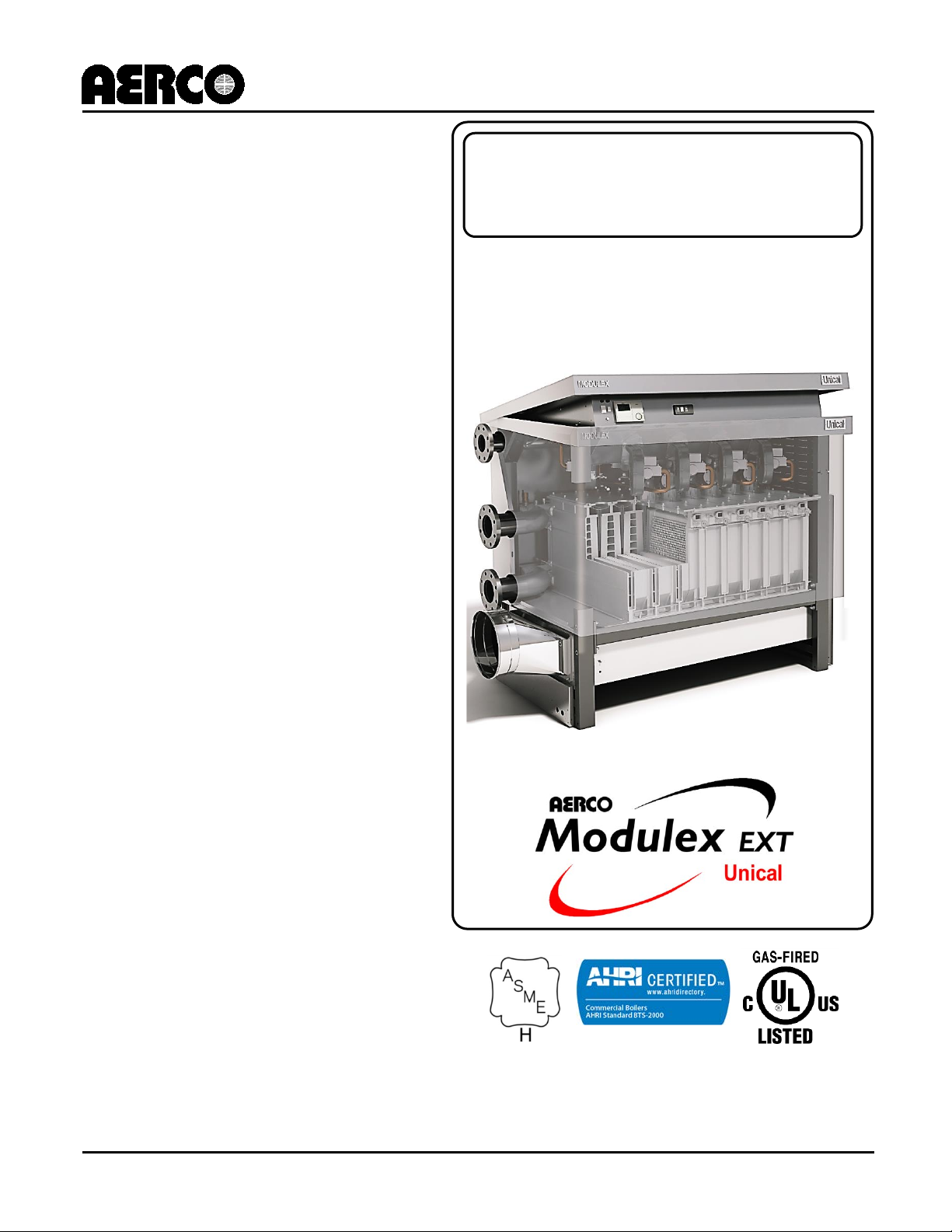
MODULEX EXT
USER MANUAL
Natural Gas Modulating &
Condensing Modular Hot
Water Boiler
COMMERCIAL CAPACITY
Covering Models:
• EXT 1530
• EXT 1912
• EXT 2295
• EXT 2677
• EXT 3060
GF-139
Installation, Operation and Maintenance
Modular Condensing Boilers
.0
Commercial Series
Latest Update: 12/01/2014
Page 2
MODULEX EXT 1530, 1912, 2295, 2677, 3060 Boilers
Installation, Operation & Maintenance Manual
DISCLAIMER
The information contained in this manual is subject to change without notice from AERCO
International, Inc. AERCO makes no warranty of any kind with respect to this material, including,
but not limited to, implied warranties of m erchantability and fitness for a particular application.
AERCO International is not liable for errors appearing in this manual, nor for incidental or
consequential damages occurring in connection with the furnishing, performance, or use of
these m aterials.
AERCO Technical Support:
(Mon–Fri, 8am-5pm EST)
1 (800) 526-0288
AERCO Document Conventions
In this document, some types of information are presented as shown in the following examples:
Message Type Example and Description
NOTE
Notes
NOTE messages indicate specific information related to the
surrounding contextual information, and highlighted for special
attention.
CAUTION!
Cautions
CAUTION messages inform of potential problems relating to the
functioning of equipment, safety to persons, harm to the
environment, and/or damage to property or equipment.
WARNING!
Warnings
WARNING messages warn of potential dangerous situations that
may result in serious injury and/or death to persons or animals.
Text is red within a red box.
How Instructions are Presented
1. Instructions are shown in a blue box with an underlined title.
2. All text, excepting in accompanying illustrations, is colored blue.
Instructions
3. All procedures are listed in steps starting with “1.” and using
letters [a), b), c), etc.], indicating sub=steps.
4. Steps that are continued on the next page have a “- Continued”
appended to the instruction title.
Page 2 of 138 AERCO Int ernational, Inc. • 100 Orita ni D r. • Blau v elt, NY 10913 OMM-0095_0E
12/01/14 Phone: 800-526-0288 GF-139
Page 3

MODULEX EXT 1530, 1912, 2295, 2677, 3060 BOILERS
Installation, Operation & Maintenance Manual
TABLE OF CONTENTS
CHAPTER 1: GENERAL INFORMATION .............................................................................................. 7
1.1 Correct Use of the Appliance ............................................................................................................................... 7
1.2 Water Treatment ................................................................................................................................................. 7
1.3 Information to Be Made Available to the User .................................................................................................... 7
1.4 Safety Warnings ................................................................................................................................................... 8
1.5 Modifications to Parts Connected To the Appliance ........................................................................................... 8
1.6 For Appliances Operating with Propane Gas ....................................................................................................... 9
1.7 Data Plate .......................................................................................................................................................... 10
1.8 Operational Requirements ................................................................................................................................ 11
1.8.1 General Requirements ............................................................................................................................ 11
1.8.2 Regulatory Requirements ....................................................................................................................... 11
1.8.3 Water Quality Requirements .................................................................................................................. 12
1.9 Tools, Materials, and Additional Equipment ..................................................................................................... 13
1.10 Disposal of Packaging and Parts ...................................................................................................................... 13
1.11 General Warnings ............................................................................................................................................ 13
1.11.1 Using the Operation and Maintenance Manual ................................................................................... 13
1.11.2 Installation and Servicing Personnel ..................................................................................................... 13
1.11.3 Installation Materials ............................................................................................................................ 13
1.11.4 Preparing Boiler for Servicing ............................................................................................................... 14
1.11.5 Returning a Boiler to Service ................................................................................................................ 14
1.11.6 Change in Ownership ............................................................................................................................ 14
1.12 Operational Limits of the Boiler....................................................................................................................... 14
CHAPTER 2: TECHNICAL FEATURES AND DIMENSIONS ................................................................ 15
2.1 Modulex EXT Technical Features ....................................................................................................................... 15
2.1.1 Temperature Control Devices: ................................................................................................................ 15
2.1.2 Control Panel (E8) Includes: .................................................................................................................... 15
2.1.3 Other Features Include: .......................................................................................................................... 15
2.2 General Boiler Operation ................................................................................................................................... 16
2.3 Dimensional Drawings ....................................................................................................................................... 17
2.4 Performance Data .............................................................................................................................................. 20
CHAPTER 3: INSTALLATION INSTRUCTIONS .................................................................................. 21
3.1 Installation Warnings and Requirements .......................................................................................................... 21
3.1.1 Appropriate Use of the Boiler ................................................................................................................. 21
3.1.2 Prerequisite System Flushing .................................................................................................................. 21
3.1.3 Installation Personnel Qualifications ...................................................................................................... 21
3.1.4 Carbon Monoxide Detector Installation ................................................................................................. 21
3.1.5 Installation Conformity Requirements.................................................................................................... 21
3.2 Code and Standards Approvals .......................................................................................................................... 22
3.3 Packaging ........................................................................................................................................................... 22
3.4 Transporting and Securing the Boiler Safely ...................................................................................................... 23
3.5 Unpacking the Boiler.......................................................................................................................................... 23
3.6 Boiler Package Contents .................................................................................................................................... 24
3.7 Boiler Location Inside a Boiler Room ................................................................................................................. 25
3.7.1 Boiler Room Safety Concerns.................................................................................................................. 25
3.7.2 Products to Avoid in the Boiler Room ..................................................................................................... 26
3.8 Recommended Clearances for Servicing ........................................................................................................... 26
3.9 Gas Connection General Information ................................................................................................................ 27
3.9.1 Natural Gas Connections ........................................................................................................................ 28
3.9.1.1 Natural Gas Piping Sizes ....................................................................................................................... 28
3.9.1.2 Natural Gas Piping Connections........................................................................................................... 28
3.9.1.3 Natural Gas Supply Pressure Requirements ........................................................................................ 28
OMM-0095_0E AERCO International, Inc. • 100 Or itani Dr. • Blau v elt, NY 10913 Page 3 of 138
GF-139 Phone: 800-526-0288 12/01/14
Page 4

MODULEX EXT 1530, 1912, 2295, 2677, 3060 Boilers
Installation, Operation & Maintenance Manual
3.9.2 Propane Gas Connections ....................................................................................................................... 28
3.9.2.1 Propane Gas Piping Sizes ..................................................................................................................... 28
3.9.2.2 Propane Gas Piping Connections ......................................................................................................... 28
3.9.2.3 Propane Gas Supply Pressure Requirements ....................................................................................... 28
3.10 Flow and Return Pipe Connections .................................................................................................................. 29
3.11 Pressure Relief Valve ....................................................................................................................................... 29
3.12 CSD-1 MANIFOLD ASSEMBLY (SUPPLIED) ........................................................................................................ 30
3.13 Determination of Primary Boiler Pump or Boiler System Pump ...................................................................... 31
3.14 Condensate Piping and Drain .......................................................................................................................... 32
3.15 Water Treatment ............................................................................................................................................. 34
3.16 Important Installation Warnings...................................................................................................................... 34
3.16.1 Oxygen Levels in the System Water Warning ....................................................................................... 34
3.16.2 Antifreeze Compatibility Warning ........................................................................................................ 34
3.16.3 Lime Scale and Corrosive Water Damage Warning .............................................................................. 35
3.16.4 Connection to Refrigeration System Warning ...................................................................................... 35
3.17 Optional Air Intake Connection ....................................................................................................................... 35
3.18 Flue Manifold Installation ................................................................................................................................ 35
3.19 Flue Exhaust Piping to Vent ............................................................................................................................. 37
3.20 Vent Starter Pieces .......................................................................................................................................... 37
3.21 Combustion Air and Ventilation Openings ...................................................................................................... 39
3.21.1 Insufficient Ventilation and Combustion Air......................................................................................... 39
3.21.2 Room Air Combustion ........................................................................................................................... 40
3.21.3 Sealed Combustion ............................................................................................................................... 40
3.22 Installation of the Exhaust and Air Intake System ........................................................................................... 41
3.22.1 Important Factors for Terminal Orientation and Location ................................................................... 42
3.22.2 Minimum and Maximum Wall Thickness .............................................................................................. 42
3.23 Vent Pipe Sizing ............................................................................................................................................... 42
3.24 Electrical Connections...................................................................................................................................... 44
3.24.1 Regulations in Force.............................................................................................................................. 44
3.24.2 Mains Electrical Supply Connection (120 V – 60 Hz)............................................................................. 44
3.24.3 Service Relay Requirement ................................................................................................................... 45
3.24.4 Electrical Requirements ........................................................................................................................ 45
3.25 Functional Wiring Diagram .............................................................................................................................. 49
3.26 Ladder Diagrams .............................................................................................................................................. 51
3.27 General Ladder Diagram .................................................................................................................................. 52
3.28 E8 Controller and BCM Terminal Assignments ................................................................................................ 52
3.29 Installation Examples ....................................................................................................................................... 55
3.30 Starting Up: Filling and De-Aerating the Boiler ................................................................................................ 57
3.30.1 Necessary Precautions for Safety ......................................................................................................... 57
3.30.2 Supply Voltage, Gas Pressure, and Water pressure .............................................................................. 57
3.31 Filling the System ............................................................................................................................................. 57
3.31.1 Necessary Precautions While Filling the System .................................................................................. 57
3.31.2 Filling Locations and Preparation.......................................................................................................... 58
3.32 Testing the Ignition Safety Shut-off Device ..................................................................................................... 60
3.33 Burner Calibration ........................................................................................................................................... 61
3.33.1 Installing the Gas Analyzer Probe ......................................................................................................... 61
3.33.2 Maximum Output Calibration ............................................................................................................... 62
3.33.3 Minimum Output Calibration................................................................................................................ 63
3.33.4 Final Check and Ignition Failure Adjustment Procedure....................................................................... 63
3.34 Sweeper Mode (Manual Control) .................................................................................................................... 66
3.35 High Altitude Adjustment ................................................................................................................................ 67
3.36 High Altitude Conversion Label........................................................................................................................ 68
3.37 Conversion from Natural Gas to Propane Gas ................................................................................................. 69
3.38 Controls and Emergency Functions ................................................................................................................. 70
3.39 Initial Boiler Ignition......................................................................................................................................... 71
3.39.1 Preliminary Checks................................................................................................................................ 71
Page 4 of 138 AERCO Int ernational, Inc. • 100 Orita ni D r. • Blau v elt, NY 10913 OMM-0095_0E
12/01/14 Phone: 800-526-0288 GF-139
Page 5

MODULEX EXT 1530, 1912, 2295, 2677, 3060 BOILERS
Installation, Operation & Maintenance Manual
CHAPTER 4: E8 CONTROLLER AND BCM MODULES ...................................................................... 72
4.1 E8 Controller ...................................................................................................................................................... 72
4.1.1 E8 Controller Features and Functions ..................................................................................................... 72
4.1.2 E8 Display Functions ............................................................................................................................... 73
4.1.3 E8 HEATING Mode Selection................................................................................................................... 74
4.1.4 E8 MENU Mode Operation (Door Open) ................................................................................................ 75
4.1.5 E8 MENU Navigation and Parameter Settings ........................................................................................ 76
4.1.6 E8 Parameter Navigation, Selection, and Setting ................................................................................... 77
4.2 BCM (Boiler Communication Module) ............................................................................................................... 78
4.2.1 BCM Features and Functions .................................................................................................................. 78
4.2.2 BCM Description ..................................................................................................................................... 78
CHAPTER 5: OPERATION OF THE E8 CONTROLLER ...................................................................... 81
5.1 Installation Menu: Initializing the E8 Controller ................................................................................................ 82
5.2 Quick Start Instructions ..................................................................................................................................... 83
5.2.1 Setting Maximum and Minimum Flow Temperature ............................................................................. 83
5.2.2 Setting Room Temperature and Outdoor Compensation....................................................................... 84
5.2.3 Setting Heating Programs and Pumps .................................................................................................... 85
5.3 Menu and Sub-Menu Descriptions .................................................................................................................... 86
5.3.1 Menus (Top Level): ................................................................................................................................. 86
5.3.2 Sub-Menus: ............................................................................................................................................. 86
5.4 General Menu .................................................................................................................................................... 87
5.5 Service Menu ..................................................................................................................................................... 89
5.6 Display Menu ..................................................................................................................................................... 91
5.7 User Menu ......................................................................................................................................................... 93
5.8 Time Program Menu .......................................................................................................................................... 95
5.9 Expert Menu ...................................................................................................................................................... 96
5.10 Other Possible Settings .................................................................................................................................. 100
5.10.1 Settings for Heating Circuit 1/2........................................................................................................... 100
5.10.1.1 Heating Adjustment With Constant Flow Temp .............................................................................. 100
5.10.1.2 Temperature Settings For Heating Circuits ...................................................................................... 100
5.10.1.3 A Second DHW Storage Tank ........................................................................................................... 101
5.10.1.4 Temperature Setting For Second DHW Storage Tank ...................................................................... 101
5.10.1.5 Swimming Pool ................................................................................................................................ 101
5.10.1.6 Swimming Pool Temperature Setting .............................................................................................. 101
5.10.1.7 Screed Dry Program (For Floor Heating Installation) ....................................................................... 101
5.10.1.8 Temperature Setting For Screed Program ....................................................................................... 101
5.10.1.9 Signal 0 – 10 V ................................................................................................................................. 101
5.10.1.10 Slope And Temperature Setting with 0 – 10 V Signal ................................................................... 101
5.10.2 Setting of DHW Circuit ........................................................................................................................ 102
5.10.2.1 Operation of Pumps In Parallel ........................................................................................................ 102
5.10.2.2 Use of a DHW Storage Tank Thermostat (On/Off) ........................................................................... 102
5.10.2.3 Antilegion ......................................................................................................................................... 102
5.10.2.4 Setting for Solar Panel Use .............................................................................................................. 102
5.11 Access Code Setting ....................................................................................................................................... 102
CHAPTER 6: TROUBLESHOOTING.................................................................................................. 103
6.1 E8 Controller Fault Codes ................................................................................................................................ 103
6.1.1 Using the Fault Code Tables.................................................................................................................. 103
6.1.2 E8 Controller Fault Codes ..................................................................................................................... 105
6.1.3 BCM (Boiler Communications Module) Fault Codes ............................................................................. 109
6.1.4 BMM (Burner Management Module) Fault Codes ............................................................................... 110
CHAPTER 7: INSPECTION AND MAINTENANCE SCHEDULE ........................................................ 113
7.1 Instructions for Inspection and Maintenance.................................................................................................. 114
7.2 Periodic Examination of Venting System ......................................................................................................... 114
OMM-0095_0E AERCO International, Inc. • 100 Or itani Dr. • Blau v elt, NY 10913 Page 5 of 138
GF-139 Phone: 800-526-0288 12/01/14
Page 6

MODULEX EXT 1530, 1912, 2295, 2677, 3060 Boilers
Installation, Operation & Maintenance Manual
7.3 Proper Procedure for Cleaning Exhaust Flue ................................................................................................... 114
7.3.1 Cleaning the Condensate Drain Line ..................................................................................................... 115
7.4 Checking CSD-1 Manifold Flow Switch ............................................................................................................ 115
7.5 Visual Inspection of the Flame......................................................................................................................... 116
7.5.1 FLAME COLOR: ...................................................................................................................................... 116
7.6 Proper Reassembly and Resealing of the Vent-Air Intake System................................................................... 116
7.7 Pressure Switch Hoses And Connections ......................................................................................................... 117
7.8 Burner / Heat Exchanger Cleaning Procedure ................................................................................................. 118
7.9 Heat and Return Sensor Resistance Values ..................................................................................................... 118
7.10 Unit Disassembly ........................................................................................................................................... 119
7.11 Cleaning the Burner Module and Combustion Chamber............................................................................... 125
7.12 Reassembly of the Burner Modules............................................................................................................... 126
7.13 Final Procedures after Maintenance ............................................................................................................. 126
7.14 Maintenance Kit Part Number ....................................................................................................................... 126
7.15 Accessory Kit Part Number ............................................................................................................................ 128
CHAPTER 8: SPARE PARTS DRAWING AND LISTS ....................................................................... 129
AERCO/MODULEX STANDARD WARRANTY ................................................................................... 137
Page 6 of 138 AERCO Int ernational, Inc. • 100 Orita ni D r. • Blau v elt, NY 10913 OMM-0095_0E
12/01/14 Phone: 800-526-0288 GF-139
Page 7

MODULEX EXT 1530, 1912, 2295, 2677, 3060 BOILERS
Installation, Operation & Maintenance Manual
CHAPTER 1: GENERAL INFORMATION
1.1 Correct Use of the Appliance
The MODULEX EXT boiler has been designed utilizing the latest heating technologies and in
compliance with current safety regulations. However, if not used or operated properly, the unit
may cause injury or death to persons, or serious damage to the equipment or surrounding objects.
The MODULEX EXT boiler is designed to be used in pumped hot water central heating systems.
Any other use of this appliance shall be considered improper, and AERCO declines any
responsibility for damages or injuries caused by the improper use of this equipment. In order to
use the equipm ent appropriately and safely according to its design, it is essential to carefully
follow the instructions in this manual.
1.2 Water Treatment
It is vital to maintain the pH of boiler water betw een 6.5 and 8. Failure to do so could result in
•
severe damage to the boiler.
• The hardness of the main water supply influences the frequency with which the heat
exchanger must be cleaned.
• In hard water areas where the main water can exceed 15°f total hardness, a scale reducing
device is recomm ended.
• In order to improve the resistance to lime scale it is recommended that the domestic hot water
temperature be as near as possible to the temperature required for end use.
• AERCO rec omm ends inspecting the state of cleanliness of the domestic hot water heat
exchanger at the end of the first year and subsequently, on the basis of the lime scale found,
this period can be extended to two years after the initial inspection.
1.3 Information to Be Made Available to the User
Go through the information in this manual with the owner/operator and m ake sure that he or she is
familiar with all necessary operating instructions, in particular:
• These instructions shall be m ade available to the end user, together with any other
literature regarding this appliance. It is highly recommended that the user keep these
documents in a safe and convenient place in order to always have them at hand for future
reference.
• It is imperative that a proper venting and exhaust system be implemented with this unit.
Refer to the AERCO Venting Application Guide (GF-115-V).
• It is absolutely forbidden to make any alterations to the boiler not in keeping with the
manufacturers recomm endations and instructions.
• It is critical to check the system’s water pressure and ensure it is at the correct pressure.
• For optimal operation of time and temperature controls, thermostats, heating controls, and
radiators, refer to separate E8 Controll er User Manual (GF-115-C).
• It is obligatory to carry out comprehensive maintenance services annually with a
combustion analysis every two years (in compliance with national and local laws).
• If the appliance is sold or transferred to another owner, or if the present user moves from
the installation site and leaves the appliance installed, ensure that the manual stays with
the boiler so that it can be consulted by the new owner and/or installer.
OMM-0095_0E AERCO International, Inc. • 100 Or itani Dr. • Blau v elt, NY 10913 Page 7 of 138
GF-139 Phone: 800-526-0288 12/01/14
Page 8

MODULEX EXT 1530, 1912, 2295, 2677, 3060 Boilers
Installation, Operation & Maintenance Manual
Failure to follow the instructions indicated in this manual, which is supplied with the boiler,
could cause injury to persons, animals or damage to property. The manufacturer shall not
be held liable for any such injury and/or damage.
1.4 Safety Warnings
WARNING!
• Children must be supervised so they do not play on, around, or
with the appliance.
• The installation, adjustment, and servicing of this appliance
must be carried out by a competent person and installed in
accordance with the current standards and regulations. Failure
to correctly install this appliance could cause injury to persons,
anim als or dam age to property. The manufacturer shall not be
held liable for any injury and/or damage.
• Servicing or repairs of the appliance must be carried out by
AERCO authorized service technicians; AERCO recommends
drawing up a service contract. Incomplete, inappropriate, or
irregular servicing could compromise the safe operation of the
appliance, and could cause injury to persons, animals or
damage to property for which AERCO shall not be held liable.
1.5 Modifications to Parts Connected To the Appliance
Do NOT carry out any modifications to the following parts:
• The boiler
• To the gas, air, water supply pipes and electrical pow er
• To the flue pipe, safety relief valve and its drainage pipe
• To the constructive components which influence the appliance’s safe operation
WARNING!
When tightening or loosening the screw pipe connections, use only
properly sized wrenches. The improper use of inadequate
equipm ent can cause damage (for example, water or gas leakages)
to the equipm ent.
Page 8 of 138 AERCO Int ernational, Inc. • 100 Orita ni D r. • Blau v elt, NY 10913 OMM-0095_0E
12/01/14 Phone: 800-526-0288 GF-139
Page 9

MODULEX EXT 1530, 1912, 2295, 2677, 3060 BOILERS
WARNING!
WHAT TO DO IF YOU SMELL GAS:
Installation, Operation & Maintenance Manual
1.6 For Appliances Operating with Propane Gas
Before installing the appliance, ensure that the gas tank has been purged. For correct instructions
on purging the tank, contact the liquid gas supplier or a competent person who is legally
authorized to provide such inform ation. If the tank has not been correctly purged, problems may
occur during ignition. If this happens contact the liquid gas tank’s supplier.
Do not store or use gasoline or other flammable vapors
or liquids in the vicinity of this or any other appliance.
• Do not try to light any appliance.
• Do not touch any electrical switch.
• Do not use any phone in the building.
• Immediately call your gas supplier from a neighbor’s
phone. Follow the gas supplier’s instructions.
• If you cannot contact your gas supplier, call the fire
department.
WARNING!
The boiler must be installed in such way as to avoid, under the
foreseen operation conditions, the freezing of the water and to
prevent the control devices from being exposed to tem peratures
lower than 5°F (15°C) or higher than 104°F (40°C). The boiler must
be protected against environm ental variations with:
• The insulation of the hydraulic pipelines and the condensate
drain.
• The adoption of specific antifreeze products in the Cold/Hot
water installation.
OMM-0095_0E AERCO International, Inc. • 100 Or itani Dr. • Blau v elt, NY 10913 Page 9 of 138
GF-139 Phone: 800-526-0288 12/01/14
Page 10
MODULEX EXT 1530, 1912, 2295, 2677, 3060 Boilers
Installation, Operation & Maintenance Manual
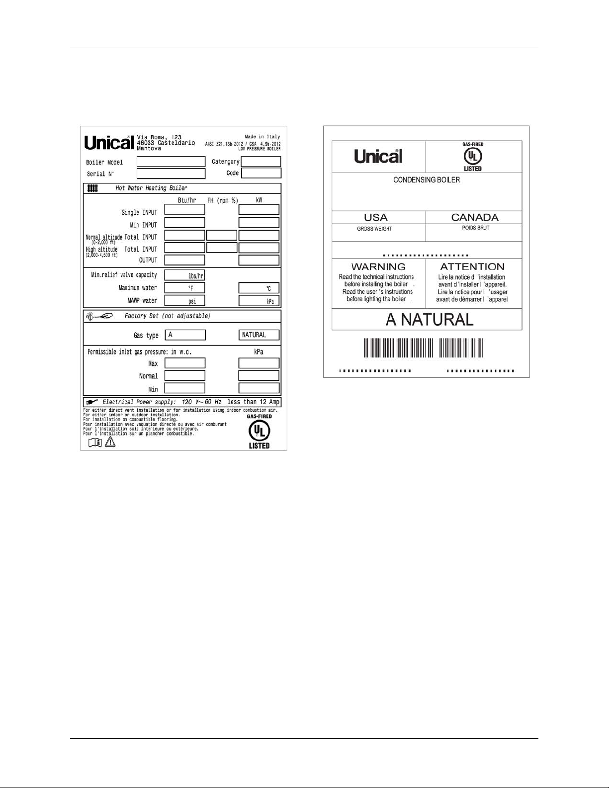
1.7 Data Plate
A sample Data Plate for a MODULEX EXT boiler is shown in the left figure below. A sample of the
Data Packaging label is shown in the right image below.
Figure 1-1: MODULEX EXT Data Plate (L) and Data Packing Label (R)
Each unit is fitted with a data plate, which may be consulted for the details on gas type, power
source, and venting classification.
Page 10 of 138 AERCO Int ernational, Inc. • 100 Orita ni D r. • Blau v elt, NY 10913 OMM-0095_0E
12/01/14 Phone: 800-526-0288 GF-139
Page 11

MODULEX EXT 1530, 1912, 2295, 2677, 3060 BOILERS
Installation, Operation & Maintenance Manual
1.8 Operational Requirements
1.8.1 General Requirements
The following instructions MUST be followed:
• The boiler must only be used for its designated purpose as described in these installation
instructions.
• Each unit is fitted with a data plate. Consult the details on this plate to verify whether the
boiler is compliant with its intended location, e.g.: gas type, power source, and venting
classification.
• Only use the boiler with the accessories and spare parts listed.
• Other combinations of accessories and products must only be used if they are specifically
designed for the intended application and do not affect the system performance or the
safety requirements.
• Maintenance and repairs must only be perform ed by trained professionals.
• Installation of a condensing gas boiler must be approved per all federal and local
governm ent codes, regulations, and laws.
• Operation of a condensing gas boiler must use a vent system that has been specifically
designed and approved for this type of boiler.
• Note that local permission and approval for the vent system and condensate water
connection to a public sewage system may be required.
1.8.2 Regulatory Requirements
You must also conform to any rules, regulations, or laws concerning the following:
• Local building codes regarding the installation.
• Local building codes concerning the air intake and outlet systems and the ven t connection.
• Regulations for the power supply connection.
• Technical rules laid down by the gas utility company concerning the connection of the gas
connection to the local gas mains.
• Instructions and standards concerning the safety equipm ent for the w ater/space heating
system.
• Installation instructions for building heating systems.
• The boiler must be located in an area where leakage of the boiler or connections will not
result in damage to the area adjacent to the boiler or to l ower floors of the structure. When
such locations cannot be avoided, it is recommended that a suitable drain pan be installed
under the boiler.
• Do not restrict or seal any air intake or outlet openings.
• If you find any defects, you must inform the owner, in writing, of the system defect and the
associated hazard.
OMM-0095_0E AERCO International, Inc. • 100 Or itani Dr. • Blau v elt, NY 10913 Page 11 of 138
GF-139 Phone: 800-526-0288 12/01/14
Page 12

MODULEX EXT 1530, 1912, 2295, 2677, 3060 Boilers
Installation, Operation & Maintenance Manual
WARNING!
Should overheating occur, or the gas supply fail to shut off, do not
turn off or disconnect the electrical supply to the pump. Instead,
shut off the gas supply at a location external to the boiler.
1.8.3 Water Quality Requirements
NOTE
For additional inform ation concerning water quality and treatm ent,
refer to AERCO technical documents Glycol Directive and AERCO
Piping Application Guide (GF-136-P).
Unsuitable heating system water can cause the formation of scale or sludge, which affects system
efficiency. It can also cause corrosion and reduce life of the heat exchanger.
• You must follow guidelines for boiler water quality.
• Thoroughly flush the system prior to filling.
• Follow the cleaning instructions.
• Never use water to fill the heating system that has been treated by reverse osmosis,
deionization, or distilled water in order to soften the water.
• Do not use inhibitors or other additives unless approved by AERCO for that purpose.
• When frost protection of the heating system is desired, only use AERCO-approved
antifreezes. The allowed maximum concentration is 50%.
• When using oxygen-permeable pipes, e. g. for under floor heating systems, you must
separ ate the system from the boiler using plate heat exchangers.
• Close the valves of the boiler while flushing the system, do not introduce any system
cleaner into the boiler loop. Flush system thoroughly to remove all system cleaner before
filling boiler.
Approved antifreeze (maximum concentration of 50%):
• Rhomar RhoGard Mutli-Metal (AL safe)
• Noble Noburst AL
Approved system cleaners:
• Noble Noburst Hydronic System Cleaner
• Fernox F3 Cleaner
• Rhomar Hydro-Solv 9100
The system cleaners from NoBurst, Rhomar, and Fernox are NOT to be used in the boiler itself.
The boiler must be closed off (valves closed) from the rest of the system or not connected while
the cleaners are in the system. The system should then be drained and then thoroughly flushed
with clean water to remove all the system cleaner.
Approved inhibitors:
• Rhomar Pro-tek 922
• Noble Noburst AL inhibitor
• AERCO/Sentinel products. See list in GF-136-P, section 2.3 - System Flushing, Treatment,
and Cleansing.
Page 12 of 138 AERCO Int ernational, Inc. • 100 Orita ni D r. • Blau v elt, NY 10913 OMM-0095_0E
12/01/14 Phone: 800-526-0288 GF-139
Page 13

MODULEX EXT 1530, 1912, 2295, 2677, 3060 BOILERS
•
•
•
•
•
•
•
•
•
Installation, Operation & Maintenance Manual
1.9 Tools, Materials, and Additional Equipment
For the installation and maintenance of the boiler you will need:
Standard tools for space heating, gas, and water fitting
Manom eter that is capable of reading both positive and negative pressures
Combustion analyzer
Digital multimeter
pH digital m eter
Metric Allen wrenches
Metric socket wrenches
1.10 Disposal of Packaging and Parts
Dispose of the boiler packaging in an environmentally sound manner.
Dispose of components of the heating system (e.g. boiler or control device), that must be
replaced in an environmentally responsible manner.
1.11 General Warnings
1.11.1 Using the Operation and Maintenance Manual
This instruction manual is an integral and indispensable part of the product and must be
retained by the person in charge of the appliance. Please read the instructions contained
in this manual carefully as they pr ovid e important information regarding the safe
installation, use and servicing of this appliance. Keep this manual in a safe place for
future referenc e.
1.11.2 Installation and Servicing Personnel
Installation and servicing must be carried out in accordance with the regulations in force
according to the manufacturer’s instructions and by legally competent authorized
persons. By definition, a competent person is a person who has a specific technical
qualification in the field of com ponents for central heating system s for domestic use,
domestic hot water production, and servicing. This person must have the qualifications
legitimized by the current laws and regulations in force.
Inappropriate, incom plete, or irr egul ar servicing could compromise the safe op eration of
the appliance, and could cause injury to persons, animals or damage t o property. The
manufacturer shall not be held liable for any such injury and/or damage.
Any repairs must be carried out by AERCO authorized technicians and using only original
spare parts. Non-observance of the above requirement may jeopardize the safety of the
appliance and void any warranties.
In the event of failure and/or faulty functioning of the appliance, switch off the boiler. Do
not attempt to make any repairs, but instead contact qualified technicians.
To guarantee the efficiency and correct functioning of the appliance it is required that the
boiler be serviced annually by a qualified person.
1.11.3 Installation Materials
The installations for the domestic hot water production MUST be built, in their entirety,
with materials (taps, pipes, fittings, etc.) approved for drinkable water.
OMM-0095_0E AERCO International, Inc. • 100 Or itani Dr. • Blau v elt, NY 10913 Page 13 of 138
GF-139 Phone: 800-526-0288 12/01/14
Page 14

MODULEX EXT 1530, 1912, 2295, 2677, 3060 Boilers
Installation, Operation & Maintenance Manual
1.11.4 Preparing Boiler for Servicing
Before carrying out any cleaning or servicing turn off the electrical supply to the boiler by
means of the ON/OFF switch and/or by m eans of the approp riate shutdown devices.
1.11.5 Returning a Boiler to Service
Before putting a boiler, which has been unused for a length of time, back into service,
rinse the entire dom estic hot water system, allowing the water to flow an appropriate
amount of tim e in order to circulate throughout the entire system.
1.11.6 Change in Ownership
If the appliance is sold or transferred to another owner, or if the present user moves from
the installation site and leaves the appliance installed, ensure that the manual stays with
the appliance so that it can be consulted by the new owner and/or installer.
1.12 Operational Limits of the Boiler
Max. boiler temperature: 180° F (80° C)
•
Max Allowable Working Temperature ASME: 200 °F
•
• Max. Allowable W orking Pressur e ASME: 92 psi
Page 14 of 138 AERCO Int ernational, Inc. • 100 Orita ni D r. • Blau v elt, NY 10913 OMM-0095_0E
12/01/14 Phone: 800-526-0288 GF-139
Page 15

MODULEX EXT 1530, 1912, 2295, 2677, 3060 BOILERS
•
•
•
Installation, Operation & Maintenance Manual
CHAPTER 2: TECHNICAL FEATURES AND DIMENSIONS
2.1 Modulex EXT Technical Features
Compact, gas fired, Low NOx, condensing boiler.
•
Comprised of one sectional boiler body, suitable as a single boil er or in a cascaded group.
•
May be installed in either an inside or outside l ocation.
•
Low internal water volume.
•
Fast response to load variations.
•
Flue exhaust outlet positionabl e on three sides.
•
Mani fold delivery and return.
•
Made up of four or more heating elements (4 to 8), cast alum inum / silicon / m agnesium.
•
Full range of modulation by variable speed blowers and premix burners.
•
Each heating element monitors its ow n water tem perature, and will individually shutdown
•
if flow is interrupted, without affecting the other burner sections.
One gas supply line.
•
• Individual modules capable of between 83 and 382.5 kBTU/hr.
These boilers are designed for use with category IV venting.
The boiler is supplied complete with all the safety and control devices in accordance with all
current regulations, and its technical and functional features comply with the regulations
prescribed by: ANSI Z21.13 / CSA 4.9 - Gas-fired low pressure steam and hot water boilers.
2.1.1 Temperature Control Devices:
• Local NTC sensor (each heating
element)
• Limit thermostat (each heating
element)
• Return NTC sensor (General)
• Safety therm ostat approved (manual
reset)
• Flow sensor BCM
• Flow NTC sensor (Gen eral)
2.1.2 Control Panel (E8) Includes:
• ON-OFF switch
• Temperature control / Boiler operation
• Fuses
• Air pressure fans
• Condensate level sensor
• Air pressure switch (anti-obstruction)
• High limit sensors
2.1.3 Other Features Include:
• NTC heat sensors for global temperature control on the flow and return.
• 0-10 V output to control variable speed primary pump
• Integral insulation with hypoallergenic synthetic wool.
Premix fiber m esh m odulating burner (premixes into the fan with autom at ic diaphragm
backflow separation from the combustion chamber).
Less than 49 dBA of noise at m aximum power.
Heating operation: instantaneous power microprocessor control, with preset param eters for
OMM-0095_0E AERCO International, Inc. • 100 Or itani Dr. • Blau v elt, NY 10913 Page 15 of 138
GF-139 Phone: 800-526-0288 12/01/14
Page 16

MODULEX EXT 1530, 1912, 2295, 2677, 3060 Boilers
•
•
•
•
•
•
•
•
•
•
•
•
•
•
•
Installation, Operation & Maintenance Manual
comparison between temperature (or calculated from the external temperature regulation)
and global temperature flow.
Operation modes:
o Ability to control power to the individual heating elements for any calibration with or
without confidential code access.
o Production of A.C.S. (Active Cooling System) by NTC sensor of priorities for control by
boiler feed pump or by three-way diverter valve controller.
E8 electronic controller included.
BCM (Boiler Communication Module) included.
Ability to control power of the individual heating elements.
Control of heat demand: constant or remote setpoint.
Monitoring of operating status and temperature.
Reporting of alarms.
Setting of parameters.
Emergency operation prevents the boiler from shutting down as a result of the interruption
of communication with a control system or any remote control unit.
Alarm managem ent.
Alarm reset input.
Warning alarm relay.
Stainless steel condensate collector tank with siphon, drain trap, and smoke chamber.
Easily removable stainless steel panels painted for outdoor installation.
Built-in air vent
2.2 General Boiler Operation
The boiler may be operated from the E8 controller or alternatively from a BCM (Boiler Cascade
Manager). The boiler management logic automatically fires the maximum number of
simultaneously operating heating elements in order to maxim ize heat production and overall
efficiency. Burner efficiency and a high heat exchange between surfaces contribute to the reliable
and efficient output power. The various components are designed to work together so that
operating tim e is shared equally among the components, thus reducing maintenance and labor
costs.
The hot water moved by the pump is pushed to the return of the primary flow of the hydraulic
separ ator. From here a second pump will distribute the hot water to the various destinations. The
cooled return water is drawn by the pump through the hydraulic separator to resume the cycle via
the boiler.
WARNING!
If installing to an outdoor location where freezing temperatures may
occur, it is necessary to install devices and/or materials to prevent
any freezing in the condensate drain and the Flow and Return
manifolds. Failure to do so may cause serious dam age to the
equipm ent.
Page 16 of 138 AERCO Int ernational, Inc. • 100 Orita ni D r. • Blau v elt, NY 10913 OMM-0095_0E
12/01/14 Phone: 800-526-0288 GF-139
Page 17
MODULEX EXT 1530, 1912, 2295, 2677, 3060 BOILERS
Installation, Operation & Maintenance Manual
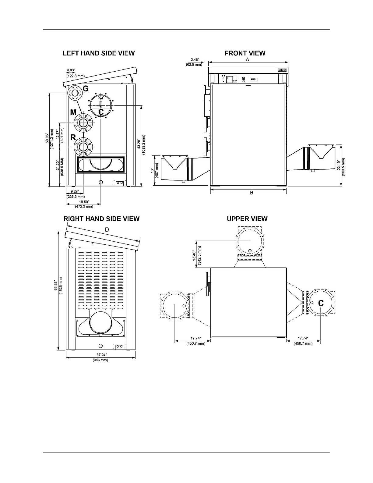
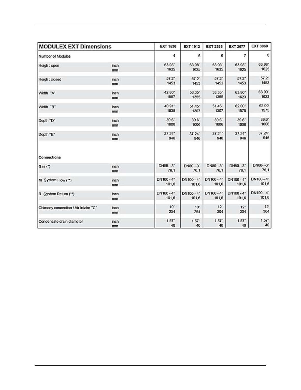
2.3 Dimensional Drawings
Figure 2-1: MODULEX EXT Dimensional Drawings
OMM-0095_0E AERCO International, Inc. • 100 Or itani Dr. • Blau v elt, NY 10913 Page 17 of 138
GF-139 Phone: 800-526-0288 12/01/14
Page 18
MODULEX EXT 1530, 1912, 2295, 2677, 3060 Boilers
(*) DN 80 – 3” ASME B16.5 Flange 150 lbs./sq. inch
Installation, Operation & Maintenance Manual
Table 2-1: MODULEX EX T Dim ens ion s and Size s
(*) DN 100 – 4” ASME B16.5 Flange 150 lbs./sq. inch
Page 18 of 138 AERCO Int ernational, Inc. • 100 Orita ni D r. • Blau v elt, NY 10913 OMM-0095_0E
12/01/14 Phone: 800-526-0288 GF-139
Page 19
MODULEX EXT 1530, 1912, 2295, 2677, 3060 BOILERS
Installation, Operation & Maintenance Manual
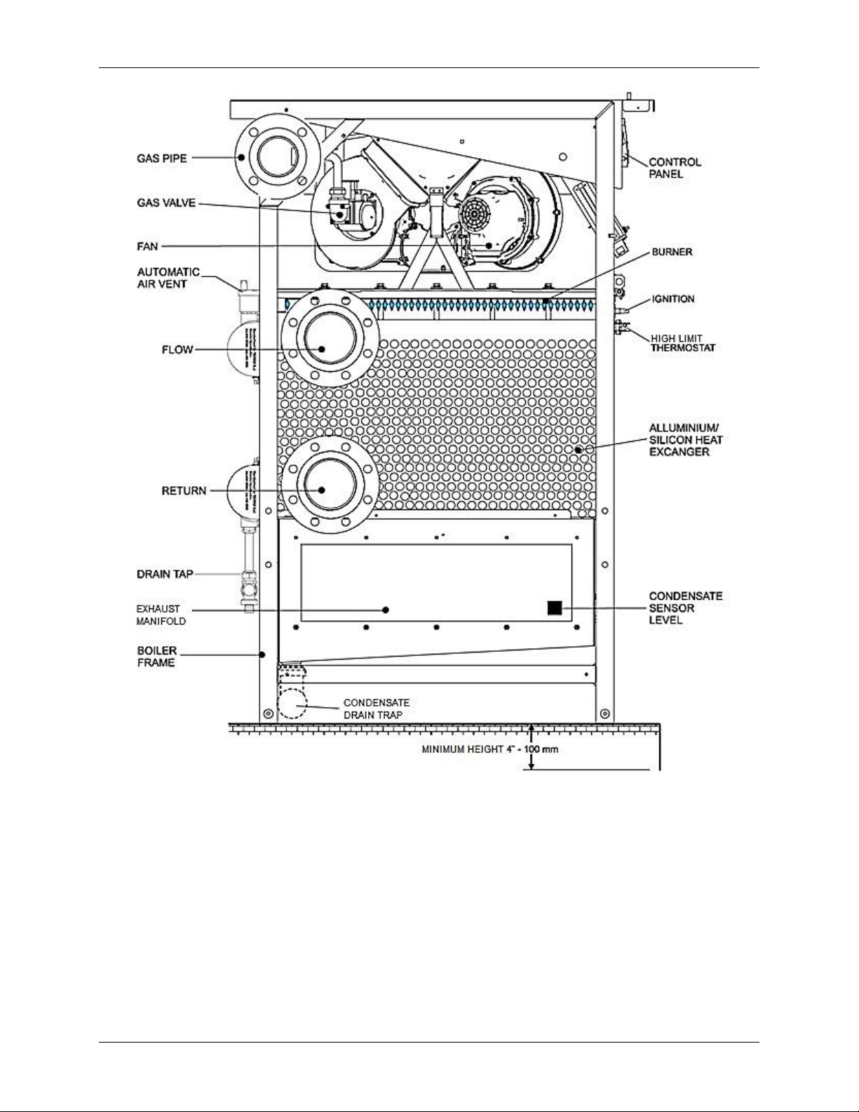
Figure 2-2: MODULEX EXT Main Components (Left Side View)
• Flue Exhaust connection is located on the RIGHT HAND side (supply condition),
but may be moved to LEFT or REAR positions.
• Air Intake connection is located on the LEFT HAND side.
• Condensate Evacuation connection is located on the RIGHT HAND side.
• Cold/Hot Flow connection is located on the LEFT HAND side.
• Cold/Hot Return connection is located on the LEFT HAND side.
• Gas Connection is located on the LEFT HAND side.
OMM-0095_0E AERCO International, Inc. • 100 Or itani Dr. • Blau v elt, NY 10913 Page 19 of 138
GF-139 Phone: 800-526-0288 12/01/14
Page 20
MODULEX EXT 1530, 1912, 2295, 2677, 3060 Boilers
Installation, Operation & Maintenance Manual
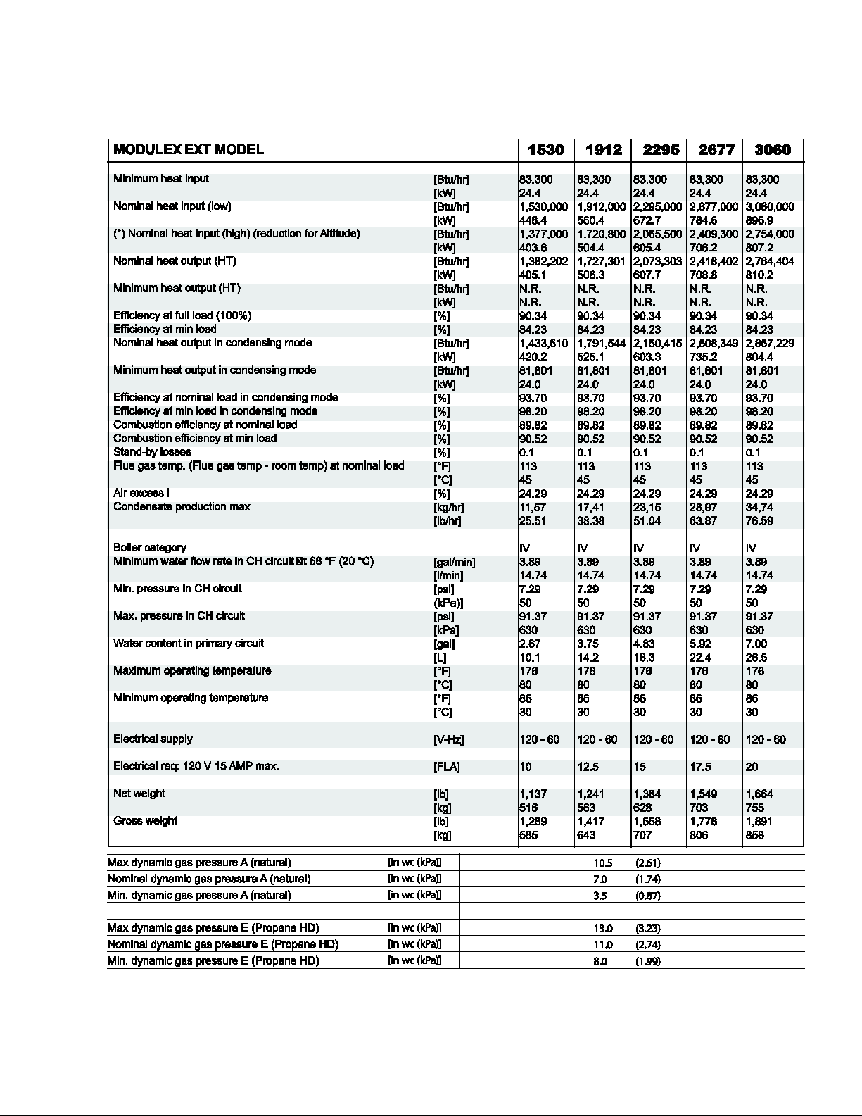
2.4 Performance Data
Table 2-2: MODULEX EXT Performance Data
NOTE
The Technical data plate is placed under the casing.
Page 20 of 138 AERCO Int ernational, Inc. • 100 Orita ni D r. • Blau v elt, NY 10913 OMM-0095_0E
12/01/14 Phone: 800-526-0288 GF-139
Page 21

MODULEX EXT 1530, 1912, 2295, 2677, 3060 BOILERS
Installation, Operation & Maintenance Manual
CHAPTER 3: INSTALLATION INSTRUCTIONS
3.1 Installation Warnings and Requirements
3.1.1 Appropriate Use of the Boiler
This boiler MUST be used in the application for which it has been expressly designed. Any other
use shall be considered improper and therefore dangerous. This boiler is designed to heat water
at a temperature below the boiling point at atmospheric pressure.
3.1.2 Prerequisite System Flushing
Before installing the boiler the following actions MUST be carried out by a competent engineer or
technician:
a) The whole system should be thoroughly flushed in order to remove any residual dirt or
grime which could compromise correct boiler operation.
b) Check that the boiler has been preset for operating with the gas type available. This is
verifiable via the data badge.
c) Check that the flue pipe has an adequate draft, does not have any constrictions or
obstructions, and that no other appliance’s flue outlets have been fitted, unless the flue
pipe is serving more than one heating appliance, according to the specific standards and
regulations in force. The connection between the boiler and flue outlet can be made only
after this verification has been carried out.
3.1.3 Installation Personnel Qualifications
The appliance MUST be installed by a qualified engineer or technician, who complies with the
technical requirements, who, under his own responsibility, guarantees the compliance of the
standards according to the latest regulations.
The appliance must be positioned so that at least the minimum operational and servicing
clearances are provided.
The boiler must be connected to a heating system which is compatible to its performance and
output.
FOR MASSACHUSETTS INSTALLATIONS: The boiler MUST be installed by a plumber or gas
fitter licensed within the Commonwealth of Massachusetts.
3.1.4 Carbon Monoxide Detector Installation
Installers MUST follow local regulations with respect to installation of Carbon Monoxide (CO)
Detectors. Also, they must follow the maintenance recommendations in this manual.
3.1.5 Installation Conformity Requirements
The installation MUST conform to the requirements of the authority having jurisdiction or, in the
absence of such requirements, to one of the following:
• United States: Installation must conform to the requirements of the National Fuel Gas
Code, ANSI Z223.1/NFPA 54.
• Canada: Installation must conform to the requirements of CAN/CSA-B149.1 - Natural Gas
and Propane Installation Code
• Where required by the authority having jurisdiction, the installation must conform to the
Standard ASME CSD-1 Controls and Safety Devices for Automatically Fired Boilers.
OMM-0095_0E AERCO International, Inc. • 100 Or itani Dr. • Blau v elt, NY 10913 Page 21 of 138
GF-139 Phone: 800-526-0288 12/01/14
Page 22
MODULEX EXT 1530, 1912, 2295, 2677, 3060 Boilers
Model
A B C
Gross Weight
(1252 mm)
(1140 mm)
(2095 mm)
(585 kg)
59.8”
(1531 mm)
44.8‘‘
(1140 mm)
82.4‘‘
(2095 mm)
1417 lb.
(643 kg)
(1531 mm)
(1140 mm)
(2095 mm)
(707 kg)
(1819 mm)
(1140 mm)
(2095 mm)
806 kg
71.6‘‘
44.8‘‘
82.4‘‘
1891 lb.
Installation, Operation & Maintenance Manual
3.2 Code and Standards Approvals
The MODULEX EXT boiler has been reviewed for com pliance with the applicable sections of
the following North American Standards:
• ANSI Z21.13/CSA 4.9: Gas-fired low pressure steam and hot water boil ers
• ASME SECTION IV: ASME Boiler and Pressure Vessel Code with addenda, Section IV:
Rules for Construction of Heating Boilers
• BTS – 2000: Testing standard m ethod to determ ine efficiency of commercial space
heating boilers.
• SCAQMD RULE 1146.2: Emissions of oxides of nitrogen from large water heaters and
small boilers and process heat ers.
• CSD-1: Controls and safety devices for aut omatically gas-fir ed boilers.
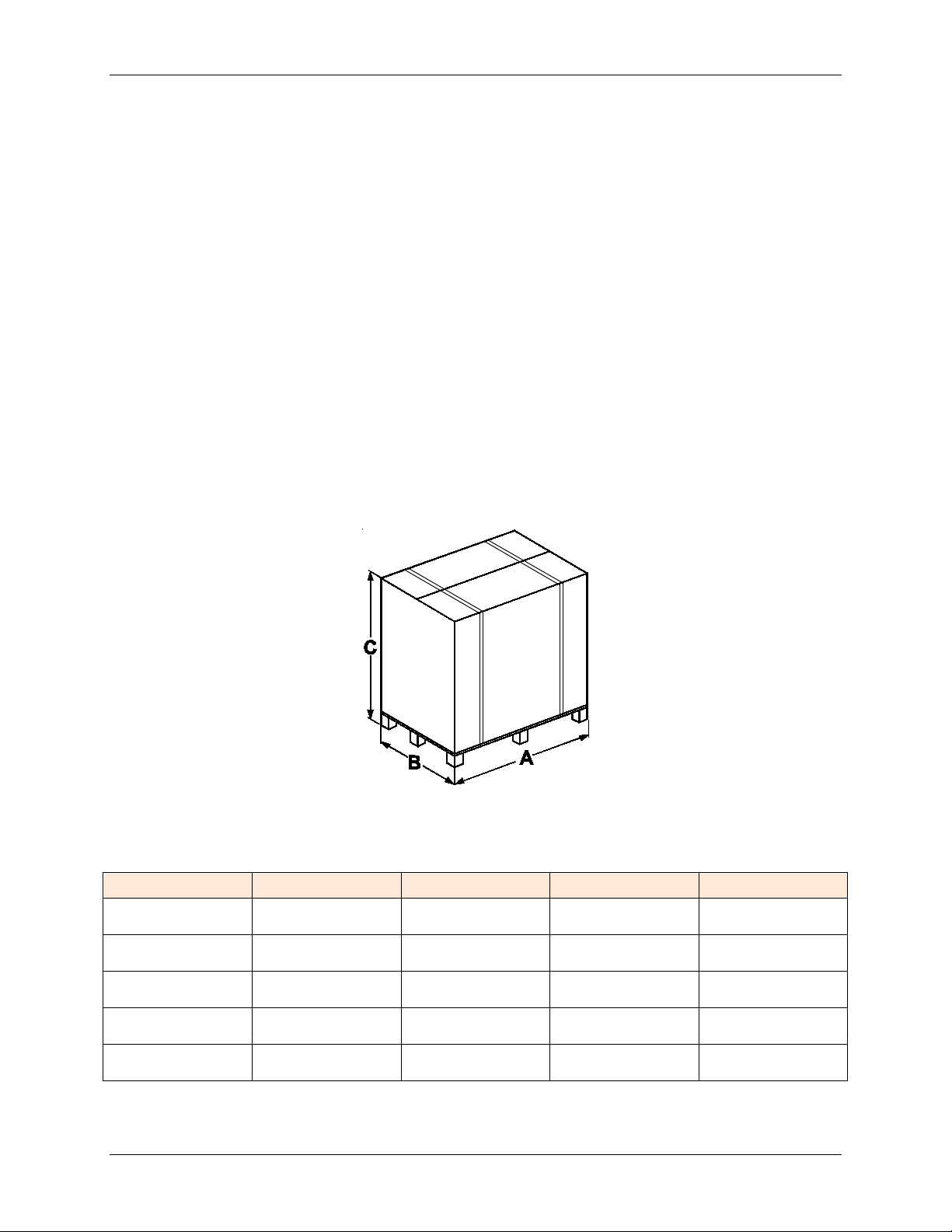
3.3 Packaging
The MODULEX EXT boiler is delivered assembled and protected by a plastic bag inside a
strong cardboard box and affi xed to a pallet. This allows the boiler to be handled by a forklift.
The boiler minimum dimension without packaging is 37.2”. By removing the sheet metal, the unit
can be moved through a standard 36” doorway.
Figure 3-1: MODULEX EXT Shipping Package and Included Parts Location
Table 3-1: MODULEX EXT Shipping Package Dimensions
EXT 1530
EXT 1912
EXT 2295
EXT 2677
EXT 3060
49.3‘‘
59.8”
71.6‘‘
(1819 mm)
44.8‘‘
44.8‘‘
44.8‘‘
(1140 mm)
82.4‘‘
82.4‘‘
82.4‘‘
(2095 mm)
1289 lb.
1558 lb.
1776 lb.
(858 kg)
Page 22 of 138 AERCO Int ernational, Inc. • 100 Orita ni D r. • Blau v elt, NY 10913 OMM-0095_0E
12/01/14 Phone: 800-526-0288 GF-139
Page 23
MODULEX EXT 1530, 1912, 2295, 2677, 3060 BOILERS
Installation, Operation & Maintenance Manual
3.4 Transporting and Securing the Boiler Safely
The boiler is susceptible to serious damage when not secured properly.
• Follow the transportation instructions on the packaging.
• Only transport the boiler using appropriate transportation equipment, such as a hand-truck
with a fastening belt or special equipment for transporting heavy equipm ent.
• When m oving the boiler, it must be secured on the transportation equipment to prevent it
from falling off.
• Protect all parts against impacts during transportation.
3.5 Unpacking the Boiler
CAUTION!
The packing elements (cardboard box, straps, plastic bags, etc.)
should be kept away from children to prevent suffocation and
choking hazards. AERCO refuses all liability for injury to persons,
anim als or dam age to property derived from not respecting the
above mentioned recommendations.
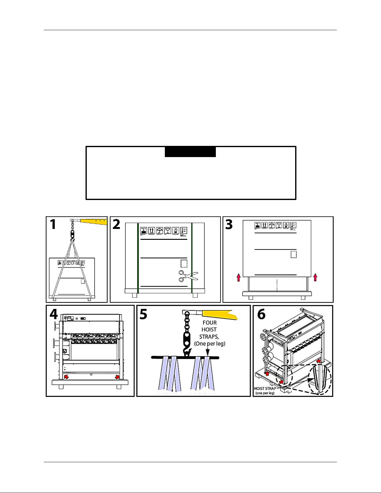
Refer to panels 1-6 of Figure 3-2 while unpacking per these instructions:
Figure 3-2: Boiler Unpacking and Hoisting
1. Prior to opening, the boiler may be moved by a hoist crane as shown (Panel 1) or forklift.
2. Remove both packing straps (Panel 2) and, finally, the cardboard box from above (Panel 3),
making sure the product is intact.
3. For the r em oval of the boiler from the pallet it is necessary to have a jib crane (P anel 5), to
OMM-0095_0E AERCO International, Inc. • 100 Or itani Dr. • Blau v elt, NY 10913 Page 23 of 138
GF-139 Phone: 800-526-0288 12/01/14
Page 24
MODULEX EXT 1530, 1912, 2295, 2677, 3060 Boilers
CSD-1
Manifold
Installation, Operation & Maintenance Manual
avoid damage to the boiler during the removal.
4. To prepare the boiler for lifting by the hoist, remove panel covers from front, rear, right, left
and top (Panel 6).
5. Use the four hoist straps (Panel 5) as slings and place one under each of four boiler legs
ensuring that strap is located UNDER the cross bars of the frame as shown in Panel 6.
6. Ensure belts are placed correctly on all four boiler legs before attempting to lift it.
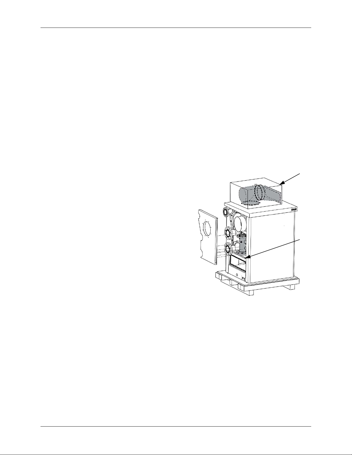
3.6 Boiler Package Contents
In the packaging, in addition to the boiler, you will also find the following contents:
ON THE LEFT HAND SIDE OF BOILER (UNDER PANEL)
• CSD-1 manifold.
CARDBOARD BOX #1
• Gasket between exhaust manifold and adaptor
• Four (4) piping elbows, a piping tee, and plastic plug for
condenstate draining system
• Hardware for assembling exhaust manifold
Box #2
Flue Parts
• Three (3) sensors:
o Remote temperature sensor
o DHW Storage tank sensor
o Outdoor temerature sensor
• Electrical resistor kit for emergency operation
• Combustion sampling port for the flue
• Metal plate and cable for power output
CARDBOARD BOX #2
• European-to-USA vent adaptor
• Two (2) gaskets for air intake and exhaust connections
• One (1) 300mm diameter gasket
INSIDE CASING ON THE BACK OF THE BOILER
• Two (2) pipes, each 39.3 feet (1 m) long for the
condensate draining system
ABOVE THE TOP COVER OF THE BOILER
• A plastic bag containing:
o This installation and user manual for the installer.
o E8 controller instruction manual.
IN A SEPARATE BOX
• Air intake adaptor for spiral ducting
• Temperature & Pressure gauge
• Flow Switch
• Pipe adaptor (rubber)
Page 24 of 138 AERCO Int ernational, Inc. • 100 Orita ni D r. • Blau v elt, NY 10913 OMM-0095_0E
12/01/14 Phone: 800-526-0288 GF-139
Page 25
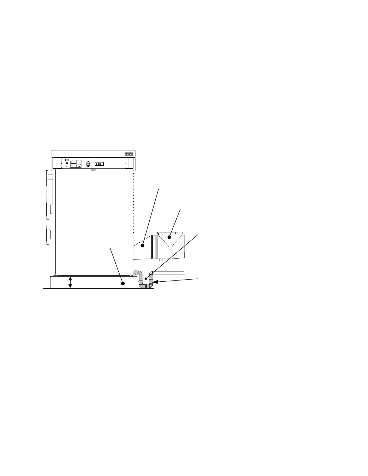
MODULEX EXT 1530, 1912, 2295, 2677, 3060 BOILERS
Boiler Housekeeping
Pad (Support Base)
European-to-USA
Flue Adapter
Flue Manifold
Installation, Operation & Maintenance Manual
3.7 Boiler Location Inside a Boiler Room
Special attention shall be paid to local regulations and laws about boiler enclosures and boiler
rooms, particularly to the minimum clearances around the boil er. The installation shall be in
com pliance with all the latest regulations and laws ab out boiler enclosures, boiler rooms,
installations of heating and hot-water system s, ventilation, vents capable of exhausting the flue
gases of cond ensing boilers, and any other applicable requirements.
The boil er can be put on a flat and sufficiently strong base with the same dimensions as the
boiler and at least 3.93’’ (100 mm) high (see Figure 3-3), in order to assemble the condensate
trap. An alternative to this base m ay be a 100mm deep well or trench next to the boiler to
accommodate the condensate “U” dr ain pipe (see Figure 3-3). After installation the boiler shall
be perfectly horizontal and stable, to reduc e any possible vibrations or noises.
Well or Trench for Condensate Drain Pipe
At Least
4” (100mm )
Condensate Drain Pipe
Figure 3-3: Boiler on Housekeeping Pad with Condensate Drain Pipe (Front View)
3.7.1 Boiler Room Safety Concerns
When selecting the position for the inst allation of the boiler please comply with the following
safety requir em ents:
• Ensure easy access to the com ponents of the boiler to facilitate maintenance.
• The room where the b oiler will be placed must always be frost free.
Do not store or use gasoline or other flammable vapors and liquids in the vicinity of this or
•
any other appliance.
Never use or st ore any chlorinated d et ergents or halog enat ed hydroc arbons (e.g. in
•
spraycans, solvents and detergents, paints, adhesives) in proximity to the boiler.
•
OMM-0095_0E AERCO International, Inc. • 100 Or itani Dr. • Blau v elt, NY 10913 Page 25 of 138
GF-139 Phone: 800-526-0288 12/01/14
For outdoor installation see Warning for Outdoor installation on page 10.
Page 26
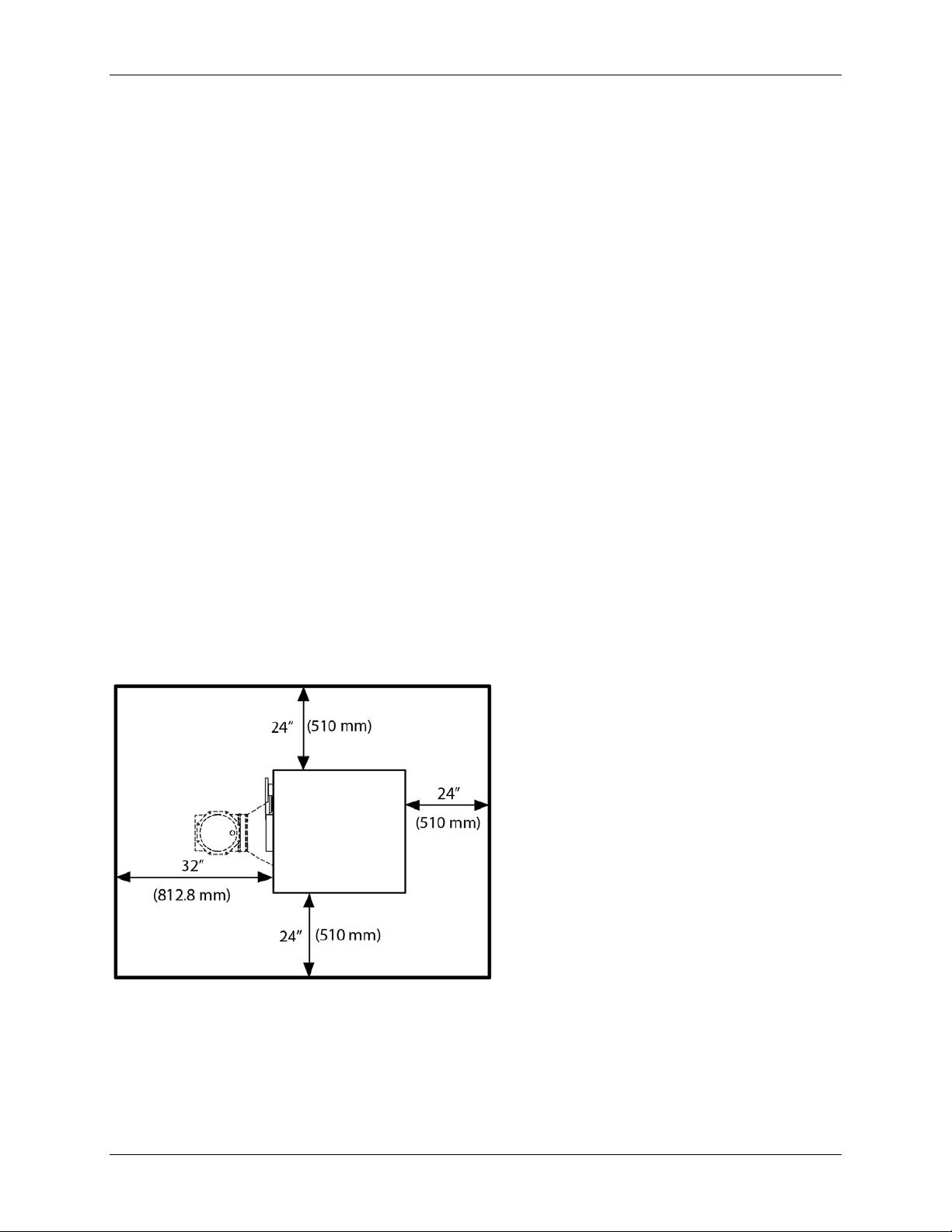
MODULEX EXT 1530, 1912, 2295, 2677, 3060 Boilers
TOP of the boiler: 24‘‘ (600 mm)
Installation, Operation & Maintenance Manual
3.7.2 Products to Avoid in the Boiler Room
Do NOT store the foll owing products in the boiler room and/or around combustion air intake
vents.
• Spray cans containing chlorocarb ons/fluorocarbons
• Ammonium and/or amm onium solutions
• Permanent wave solutions
• Chlorinated waxes and/or cleaners
• Chlorinated swimming pool chemicals
• Calcium chloride used for thawing
• Sodium chloride used for water soft ening
• Refrigerant leaks
• Paint or varnish rem overs
• Hydrochloric acid/muriatic acid
• Cements and glues
• Antistatic fabric soft en ers used in clothes dryers
• Chlorine-type bleaches, deterg ents, and cleaning solvents
• Adhesives used to fasten building products
• other damaging or flammable products
3.8 Recommended Clearances for Servicing
Recommended clearances around the boiler are listed below (see Figure 3-4):
FRONT of the boiler: 24’’ (600 mm)
UNVENTED side: 24’’ (600 mm)
VENTED side: 32’’ (600 mm)
FLOOR/GROUND: 4’’ (100 mm)
REAR of the boiler: 24’’ (600 mm)
Figure 3-4: MODULEX EXT Boiler Clearances
It is recomm ended to provide the boiler with the clearances as shown in the drawing in order to be
able to perform normal service and cleaning operations. Minimum required clearances depend on
the piping and venting configuration. For further details, contact your loal manufacturer’s
representative.
Page 26 of 138 AERCO Int ernational, Inc. • 100 Orita ni D r. • Blau v elt, NY 10913 OMM-0095_0E
12/01/14 Phone: 800-526-0288 GF-139
Page 27

MODULEX EXT 1530, 1912, 2295, 2677, 3060 BOILERS
Installation, Operation & Maintenance Manual
3.9 Gas Connection General Information
For natural gas connections, refer to section 3.9.1. For propane gas connections, refer to
Section 3.9.2.
The gas supply connection must comply with local regulations or, if such regulations do not exist,
with the National Fuel Gas Code, ANSI Z223.1/NFPA 54.
For Canada, the gas connection must comply with local regulations or, if such regulations do not
exist, with the CAN/CSA-B149.1 - Natural Gas and Propane Installation Code.
Before installing the boiler it is recommended t hat all the supply piping be thoroughly cleaned in
order to remove any residual grim e which could compromise the boilers correct functioning.
As a safety measure against gas leaks, AERCO recommends installing a surveillance and
protective system made up of a gas leakage d etector combined with an on-off solenoid valve on
the gas supply line.
The boiler and its individual shutoff valve must be disconnected from the gas supply piping system
during any pressure testing of that system at test pressures in excess of 1/2 PSI (3.5kPa).
The boiler must be isolated from the gas supply piping system by closing its individual manual
shutoff valve during any pressure testing of the gas supply piping system at test pressures equal
to or less than 1/2 PSI (3.5 kPa).
Clause 1.34.1b.12: Provisions for combustion and ventilation air in accordance with the section
“Air for Combustion and Ventilation,” of the National Fuel Gas Code, ANSI Z223.1/NFPA 54, or
Sections 8.2, 8.3 or 8.4 of Natural Gas and Propane Installation Code, CAN/CSA B149.1, or
applicable provisions of the local building codes.
Clause 1.34.1b.21: A sediment trap must be provided upstream of the gas controls.
WARNING!
THE GAS CONNECTION MUST BE INSTALLED BY A
REGISTERED ENGINEER WHO MUST COMPLY WITH THE
REGULATIONS IN FORCE AND TO THE REQUIREMENTS
INDICATED BY THE LOCAL GAS SUPPLIER. AN INCORRECT
INSTALLATION CAN CAUSE INJURY OR DEATH TO
PERSONS, ANIMALS OR DAMAGE TO PROPERTY. THE
MANUFACTURER SHALL NOT BE HELD LIABLE FOR ANY
INJURY AND/OR DAMAGE DUE TO INAPPROPRIATE
INSTALLATION.
Do not use the boiler for another type of gas than indicated on the
identification plate of the boiler. This will cause improper functioning
and can damage the boiler. The suitable gas type for the boiler is
indicated on the packaging label and on the data plate boiler.First
check the identification plate on the boiler for the suitable gas type.
Always check the safety of the gas pipe system by means of a soap
bubble test using a leak-search spray.
OMM-0095_0E AERCO International, Inc. • 100 Or itani Dr. • Blau v elt, NY 10913 Page 27 of 138
GF-139 Phone: 800-526-0288 12/01/14
Page 28

MODULEX EXT 1530, 1912, 2295, 2677, 3060 Boilers
•
•
•
Installation, Operation & Maintenance Manual
3.9.1 Natural Gas Connections
Natural Gas Piping Sizes 3.9.1.1
Contact your local gas supplier for natural gas pipe sizes and meter types.
Natural Gas Piping Connections 3.9.1.2
The boiler g as pipe is equipped with external 3’’ ASME B16.5 flange, onto which the tail
piece of the gas shut off valve can be connected. Use appropriate sealing.
The connection to the boiler must include a suitable method of disconnection and a gas
control valve must be installed adjac ent to the boiler for isolation purp oses.
Natural Gas Supply Pressure Requirements 3.9.1.3
The nominal inlet working gas pressure measured at the boiler should be 7” W.C. (18 mbar)
for natural gas. Maxim um pressure with no flow (lockup) or with the boiler running is 10.5
inches W.C. Minimum pressure with gas flowing (verify during boiler startup) is 4.0 inches
W.C.
3.9.2 Propane Gas Connections
Propane Ga s Pi pin g Si zes 3.9.2.1
Contact your local gas supplier for Propane gas pipe sizes, tanks, and 100% lockup gas
pressure regulator.
Propane Ga s Pi pin g C onnec tions 3.9.2.2
The boil er pipe is provided with external 3’’ ASME B16.5 flange, onto which the t ail piec e of
the gas shut off valve can be screwed. Use appropriat e sealing.
The connection to the boiler must include a suitable method of disconnection. Use a gas shut
off valve compatible with propane gases. A sediment trap must be provide upstream of the
gas controls.
Propane Gas Supply Pressure Requirements 3.9.2.3
Pressures required at gas valve inlet pressure port:
Nominal gas pressure is 11 inches W.C.
Maximum gas pressure is 13 inches W.C. with no flow (lockup) or with boiler running.
Minimum gas pressure is 8 inches W.C. with gas flowing (verify during boiler startup).
NOTE
Ensure that the high gas pressure regulator is installed at least 6 to
10 feet upstream of the boiler.
Page 28 of 138 AERCO Int ernational, Inc. • 100 Orita ni D r. • Blau v elt, NY 10913 OMM-0095_0E
12/01/14 Phone: 800-526-0288 GF-139
Page 29
MODULEX EXT 1530, 1912, 2295, 2677, 3060 BOILERS
Installation, Operation & Maintenance Manual
3.10 Flow and Return Pipe Connections
The cold and hot water flow and return circuits must be connected to the boiler via the
resp ective 4” M and R connections as indicated in Table 2-1.
When determining the size of the cold/hot water circuit pipes it is essential to bear in mind the
pressure losses induced by any of the system’s components and by the configuration of the
system.
When planning the routing of the cold/h ot water piping, take the necessary precautions to avoid
air traps and pockets and to facilitate the continuous purging of the system.
WARNING!
• Before installing the boiler we recomm end that the system is
flushed out with a suitable cleaning product in order to eliminate
any m etallic tooling or welding residues, or oil and grime, which
could reach the boiler and affect the proper functioning of the
boiler.
• Ensure that the system piping is NOT used for earth grounding
of electrical or telephone systems. Such grounding of system
piping is unsuitable and can cause serious damage to the
piping, boiler, and radiators.
• IT IS ABSOLUTELY FORBIDDEN TO FIT ON-OFF VALVES IN
THE PIPING BEFORE THE REQUIRED SAFTEY DEVICES.
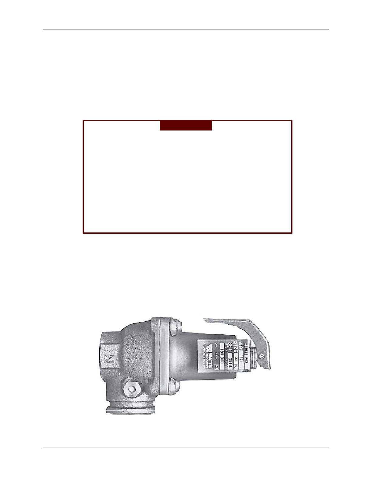
3.11 Pressure Relief Valve
A pressure relief valve (Figure 3-5) must be fitted on the CSD-1 manifold. It must be
dim ensioned for the capacity of the boiler and must comply with the ANSI/ASME
CSA 4.9
Pressure vessel, and Pressure Piping Code, as applicable.
The boiler ships with an 80 psi pressure relief valve for installation into the CSD-1 manifold
header. Lower system pressures will require lower rated pressure reli ef valves (not supplied).
Boiler and Pressure Vessel Code, Section IV (‘’Heating Boilers’’), or CSA B51, Boiler,
ANSI Z21.13 /
Figure 3-5: Pressure Relief Val ve
OMM-0095_0E AERCO International, Inc. • 100 Or itani Dr. • Blau v elt, NY 10913 Page 29 of 138
GF-139 Phone: 800-526-0288 12/01/14
Page 30
MODULEX EXT 1530, 1912, 2295, 2677, 3060 Boilers
Flow S witch
3/4” Pressure Relief
Installation, Operation & Maintenance Manual
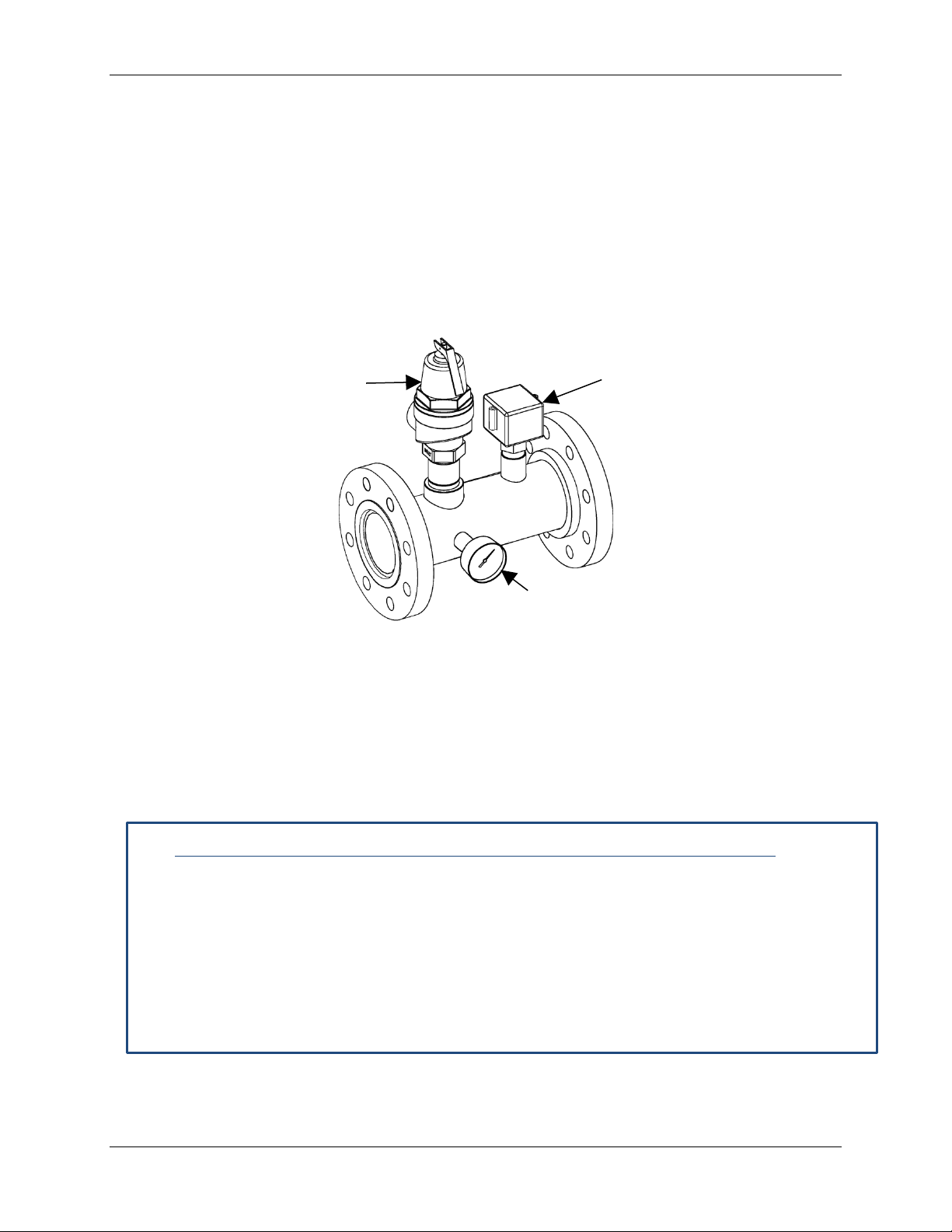
3.12 CSD-1 MANIFOLD ASSEMBLY (SUPPLIED)
The installation of a flow switch, pressure/temperature gauge, and an ASME compliant safety
pressure relief valve designed for the boiler output capacity are required. These major
components are supplied with the boiler and must be assembled and wired when installing the
boiler at the site. The manifold assembly components supplied are:
• 3/4” Pressure Relief Val ve
• Flow Switch
• Pressure/Temperature Gauge
The pressure relief valve and all other manifold components are shown in Figure 3-6.
Valve
Pressure/Temperature
Gauge
Figure 3-6: Manifold Assembly and Components
To install the pressure reli ef valve and the other components shown, proceed as shown in
Instruction 4.0, below.
NOTE
Use T eflon tape or a suit able pipe joint compound for com ponent
and piping connections described in the following steps. Refer to
Figure 3- 6 for component identification.
Installing the Pressure Relief Valve and Other Components
1. Attach manifold to the outlet supply connection on the boiler via the flanged connections.
2. Cut the flow switch paddle. For EXT models 1530 to 3060, cut for 4” pipe as directed in
the flow switch paddle packaging. For installations expecting less than a 10 gpm flow,
the switch m ust be adjusted as follows:
a) With no flow, turn adjustm ent screw on the switch counter-clockwise until the switch
trips.
b) Then turn screw 1/2 turn clock-wise and continue installation.
Page 30 of 138 AERCO Int ernational, Inc. • 100 Orita ni D r. • Blau v elt, NY 10913 OMM-0095_0E
12/01/14 Phone: 800-526-0288 GF-139
Page 31

MODULEX EXT 1530, 1912, 2295, 2677, 3060 BOILERS
Installation, Operation & Maintenance Manual
Installing the Pressure Relief Valve and Other Components – Continued
3. Connect the foll owing components to the tapped holes in the manifold assembly (Figure 3-
6):
• 3/4” Pressure Relief Val ve
• Flow Switch
• Pressure/Tem perature Gauge
NOTE
It is important to next ensure that the flow switch is installed with the
“flow” arrow pointing in the direction of the flow.
4. Check t o ensure t hat all c omponents are secu r el y tight ened and that the flow switch
paddle moves freely without interference.
5. Locate the BMM module with the “FL” label (Figure 3-7), and remove the bl ac k jum p er
wire from the t erminals of th e connector shown i n the d et ail of Figure 3-7. Connect the two
flow switch wires to th e tw o term inals. Flow switch wires have no pol arity, so can be
inserted without regard to position.
DETAIL
Remove this black jumper and
insert the two wires from the flow
switch into terminal connector.
Figure 3-7: BMM Location and Flow Switch Connection
3.13 Determination of Primary Boiler Pump or Boiler System Pump
The following table gives an indication of the pump’s flow rate in function of the ∆t of the
primary circuit if the installation has a mixing header.
The size of the pumps must be determined by installers or technical engineers according to
boiler data and syst em design.
OMM-0095_0E AERCO International, Inc. • 100 Or itani Dr. • Blau v elt, NY 10913 Page 31 of 138
GF-139 Phone: 800-526-0288 12/01/14
Page 32

MODULEX EXT 1530, 1912, 2295, 2677, 3060 Boilers
Boiler Model
EXT 1530
EXT 1912
EXT 2295
EXT 2677
EXT 3060
Min. flow rate demanded in
Max flow rate demanded in
Max flow rate demanded in
Installation, Operation & Maintenance Manual
Table 3-2: MODULEX EXT Minimum/Maximum Flow Rates
Min. flow rate demanded in
gpm ∆T 27°F (15°C)
gpm ∆T 36°F (20°C)
gpm ∆T 27°F (15°C)
gpm ∆T 36°F (20°C)
5 5 5 5 5
4 4 4 4 4
102 128 153 179 205
77 96 115 134 153
The water side resistance curve of the b oiler is shown in the diagram in Figure 3-8.
The pump is not an integral p art of the boiler. It is recommended to choose a pump with the rate
and delivery head at about 2/3 of its characteristic heating curve.
3.14 Condensate Piping and Drain
To avoid condensat e collecting inside the combustion exhaust system, the condenate piping
must slope toward the drain at least 3/8 in./ft (30 mm/m).
The liquid column, inside the condensate siphon, (see Condensate Siphon Filling Plug in Figure
3-9) needs to be filled with water aft er installation. The minimum height of the water in the
column, when all the fans are in operati on, must be at least 25 mm (1 in.).
Page 32 of 138 AERCO Int ernational, Inc. • 100 Orita ni D r. • Blau v elt, NY 10913 OMM-0095_0E
12/01/14 Phone: 800-526-0288 GF-139
Figure 3-8: MODULEX EXT Water Side Pressure Losses
NOTE
The use of a mixing header fitted betw een the boiler circuit and the
system circuit is always advisable. It becomes INDISPENSABLE if
the system requires flow rates superior to the maximum permitted
boiler flow rates, which is to say lower than 27° F (15 K).
Page 33

MODULEX EXT 1530, 1912, 2295, 2677, 3060 BOILERS
Installation, Operation & Maintenance Manual
In order to avoid ice formation while the boiler is operating, which can cause the boiler to stop
functioning, the entire condensate evacuation system must be well insulated. Not e th at it is
forbidden to evacuate the condensate through an open gutter to prevent the risk of ice forming
and avoid exposure of the corrosive condensate to the ext ernal environment.
The condensate must be neutralized before being evacuated to the sewer, which can be
achieved by mixing the c ondensate with lime or w ith drain water coming from washing
machines, dish washing machines, etc., which normally has a b ase pH.
The connection to the sewer will be through a closed, but visible drain. Given the high acidity
(pH 3 to 5) of the condensate, only plastic m aterial may be used for the condensat e evacuation
pipes. Moreover it m ust be dim ensioned and constructed so as to allow the correct out-flow to
the drain, preventing any bottleneck and any l eakage.
Consult local codes regarding condensat e neutralization. Neutralization may be obtained by
mixing it with the buildings drain water or with limestone, which normally has a base pH.
AERCO Internati on al offers a condensate neutralizing kit and a neutalizing tank, for prep aring
conden sate wast e for safe evacuati on into a sew er system, if other means of neutralizing the
waste are not available.
Figure 3-9: MODULEX EXT Condensate Piping
The outlet of the condensate drain pipe exits from the right side of the b oiler, just below the
RIGHT-SIDE flue outlet opening.
IMPORTANT NOTE
If it is not possible to use a 4’’ (101mm) base or housekeeping pad
on which to place the boiler, install the boiler on the floor and
provide a well or trough (minimum of 4’’ - 101 mm deep) in w hich to
lodge the U of the condensate piping. See Figure 3-9.
WARNING!
• Before commissioning the boiler, fill the condensate siphon with
water, at the dedicated filling-up plug. See Figure 3-9.
• Do not install the condensate drain where freezing may occur.
Use m aterials approved by the authority having jurisdiction in your area. In the absence of such
authority, PVC and CPVC pipe must comply with ASTM D1785, F441 or D2665. Cement and
primer must comply with ASTM D2564 or F493. For Canada, use ULC certified PVC or CPVC
pipe, fittings and cement. Periodic cleaning of the condensate disposal system must be
carried out.
OMM-0095_0E AERCO International, Inc. • 100 Or itani Dr. • Blau v elt, NY 10913 Page 33 of 138
GF-139 Phone: 800-526-0288 12/01/14
Page 34

MODULEX EXT 1530, 1912, 2295, 2677, 3060 Boilers
Installation, Operation & Maintenance Manual
3.15 Water Treatment
The chemical/physical composition of the heating syst em’s water is fundamental for the boiler’s
correct operation and safety.
Among the problems caused by poor quality of feed water, the m ost frequent and the most
serious is the buildup of deposits on boiler therm al exchang e surfaces.
Less frequent, but also serious, are deposits on the water circulating piping surfaces. Because
of the low thermal conductivity of mineralization desposits caused by im properly treated water,
the thermal exchange efficiency may be seri ously r educed, and can result in very dangerous
localized overheating.
AERCO suggests treating and conditioning feed water for the heating circuit in the following
cases:
• When the hardness of the water is higher than 9 grains (15°f).
• For cold/hot water installations with large water content.
• Renewal of the water system due to uncontrolled leakages.
• Subsequent refilling of the system due to maintenance work on the installation.
• Presence of different m etals in the water circuit.
Properly treated syst em and feed water will eliminate or substanti ally reduce the following
problems:
• lim e scale deposit
• corrosion sludge
• deposits
• microbiological growths (molds, bacteria etc.)
An appropriate treatment of the supply water will prevent the above stated problems and will
maintain the correct operation and efficiency of the boiler over time.
In order to prop erly treat water for use in a hydronic boiler heating system, the following
physical/chemical characteristics must be addressed.
Water Hardness: If water hardness is over 6 to 9 grains, a water softener must be used.
Sediment: If sedim ent is present in the system , a sediment filter or other appropriate device,
must be used.
Water pH: If water has a pH above 8, or b el ow 5, then the water must be treated to provide a
medium pH of between 5 and 8.
The system water to be judged for water characteristics should be taken from the return pipe of
the prim ary circuit downstream of the circulating pump.
3.16 Important Installation Warnings
3.16.1 Oxygen Levels in the System Water Warning
All necessary precautions must be taken for preventing the form ation and localization of
oxygen in the system’s water. For this reason, ensure that the plastic piping used in
under-floor heating systems is impermeable to oxygen.
3.16.2 Antifreeze Compatibility Warning
If any anti-freeze solutions are used ensure that they are compatible with aluminum and
any other boiler components and materials.
Page 34 of 138 AERCO Int ernational, Inc. • 100 Orita ni D r. • Blau v elt, NY 10913 OMM-0095_0E
12/01/14 Phone: 800-526-0288 GF-139
Page 35

MODULEX EXT 1530, 1912, 2295, 2677, 3060 BOILERS
AIR INTAKE
Installation, Operation & Maintenance Manual
3.16.3 Lime Scale and Corrosive Water Damage Warning
Any damage caused to the boiler due to the form ation of lime scale or by corrosive w ater
will not be covered by the warranty. Appropriate steps must be taken to ensure the indirect
tank water heater does not become plugged by scale caused by hard water or sediment. If
the indirect tank water heater becomes plugged by either scaling from hard water or
sediment it is not the responsibility of AERCO International.
3.16.4 Connection to Refrigeration System Warning
The boiler, when used in connection with a refrigeration system, must be installed so the
chilled medium is piped in parallel with the boiler with appropriate valves to prevent the
chilled m edium from entering the boiler.
The boiler piping system of a hot water boiler connected to heating coils located in air
Handling units where they may be exposed to refrigerated air circulation must be equipped
with flow control valves or other automatic means to prevent gravity circulation of the boiler
water during the cooling cycle.
3.17 Optional Air Intake Connection
Install air intake connector as shown in Figure 3-10. Use silicone to lubricate the internal surface of
the seals before assembling.
For air intake connection piping use only:
• 10” for Modulex EXT 1530, 1912
• 12” for Modulex EXT 2295, 2677, 3060
The Air Intake Connector that ships with the unit is for spiral ducts only. For other m aterial s,
please contact AERCO directly.
AIR INTAKE
PIPING
(NOT SUPPLIED)
CONNECTOR
(SUPPLIED)
Figure 3-10: MODULEX EXT Air Intake Connection
3.18 Flue Manifold Installation
To assem ble the flue manifold to the boiler flue exhaust opening, retrieve the ten (10) nuts and
washers from the plastic bag, shipped with the boiler, and affix to the boiler opening per Figure 3-
11. The Manifold may be installed on left, front, or rear. If switching to left or rear positions,
unused outlet should be covered with the plate and gasket removed from outlet being used.
OMM-0095_0E AERCO International, Inc. • 100 Or itani Dr. • Blau v elt, NY 10913 Page 35 of 138
GF-139 Phone: 800-526-0288 12/01/14
Page 36

MODULEX EXT 1530, 1912, 2295, 2677, 3060 Boilers
FLUE MANIFOLD
GASKET FOR ATTACHING
FLUE MANIFOLD
NUTS (10)
WASHERS (10)
Installation, Operation & Maintenance Manual
RECTANGULAR GASKET
EUROPEAN-TO-USA
FLUE ADAPTER
Figure 3-11: Connection of Exhaust Manifold To Boiler Flue Exhaust Outlet
For venting systems in the USA, it is necessary to assemble the Euro-to-USA adaptor to the flue manifold
as shown in Figure 3-12.
GASKET FOR ATTACHING
EUROPEAN-TO-USA FLUE
ADAPTER
EUROPEAN-TO-USA
FLUE ADAPTER
Page 36 of 138 AERCO Int ernational, Inc. • 100 Orita ni D r. • Blau v elt, NY 10913 OMM-0095_0E
12/01/14 Phone: 800-526-0288 GF-139
Figure 3-12: Assembly of USA-to-European Flue Adaptor to Flue Manifold
NOTE
The gasket may seem large. It is intentionally designed to produce a tight fit.
Page 37

MODULEX EXT 1530, 1912, 2295, 2677, 3060 BOILERS
Installation, Operation & Maintenance Manual
3.19 Flue Exhaust Piping to Vent
In a condensing boiler the flue exhaust is evacuated at a ver y low temperature (maximum of
about 183°F / 84°C). Thus, it is necessary that the chim ney be impermeble to the condensate of
the combustion products and be made of corrosion resistant materials.
The different joints must be well sealed and equipped with suitable gasket s in order to prevent
the escape of condensate and prevent the ingress of air.
To determ ine the proper cross section and height dimensions of the flue exhaust piping, refer to
national and local codes.
In order to prevent the formation of ice during the operation, the temperature of the intern al wall
of the flue exhaust system should not be below 32 °F (0 °C) throughout its length.
For efficient venting of the combustion exhaust and to address conden sation due to lower
external temperatures, ensure that combustion condensation is discharged into the boiler
conden sate tray or into an other separate collection pan according to the installation.
A test nipple, for measuring combustion gases, should be installed onto the first three feet of the
exhaust manifold flue. To do this, a h ol e with a diameter of 0.83‘‘ is drilled in a convenient
location for testing and the test nipple hardware assembled to the Flue pipe as shown in Figure
3-13.
Figure 3-13: Installation of Test Nipple into Flue Manifold Piping
NOTE
Damage caused by mistakes in installation, failure to complete the
instructions as written, or the improper use of the flue system are
not the responsibility of the supplier.
3.20 Vent Starter Pieces
All vent starter pieces for the Modulex EXT 1530 through 3060 can be purchased directly from
the vent manufacturer.
OMM-0095_0E AERCO International, Inc. • 100 Or itani Dr. • Blau v elt, NY 10913 Page 37 of 138
GF-139 Phone: 800-526-0288 12/01/14
Page 38

MODULEX EXT 1530, 1912, 2295, 2677, 3060 Boilers
Stainless
Contact vent manufacturer
Polypropylene
Contact vent manufacturer
PVC
58115-1
EXT 2295
Stainless
Contact vent manufacturer
Polypropylene
Contact vent manufacturer
PVC
58115-2
DIAMETER REDUCTION
WORM-DRIVEN HOSE CLAMP
WASHERS (8 EACH)
SCREWS (8 EACH)
FLUE MANIFOLD
Example Vent Starter Piece
ACCESS POINT FOR
CLEANING (underneath)
Installation, Operation & Maintenance Manual
ADAPTOR CONNECTOR
GASKET
EUROPEAN-TO-USA
STANDARD FLUE ADAPTER
Figure 3-14: Flue Exhaust Diameter Reduction Adaptor Kit
Table 3-3: Vent Part Numbers
Model Dia. Material Part Number
EXT 1530
EXT 1912
EXT 2677
EXT 3060
In the case of PVC venting, the flue venting pipe is affixed to the adapter using RTV liquid
silicone and then clamped with a worm -driven Hose Clam p.
When using non-metallic (plastic) venting materi als, use schedule 40 or thicker, single-wall,
uninsulated pipes. When using non-metallic (plastic) vent systems for Canadi an inst allations,
per CSA B149.1, use vent systems that are certified to the standard for Type BH Gas Venting
Systems, ULC-S636.
10”
12”
Please note that 10” and 12” PVC can be heavy and expensive. Alternative vent materials, such
as AL29-4C or polypropylene should be considered prior to installation.
The plastic components, primers and glues of the certified vent system must be from a single
system manufacturer and not mixed with other manufacturer’s vent system parts.
Page 38 of 138 AERCO Int ernational, Inc. • 100 Orita ni D r. • Blau v elt, NY 10913 OMM-0095_0E
12/01/14 Phone: 800-526-0288 GF-139
Page 39

MODULEX EXT 1530, 1912, 2295, 2677, 3060 BOILERS
INSTAL FLUE PIPING
HOSE CLAMP
FLUE VENT PIPE
ADAPTER ASSEMBLY
Test Nipple
flue start.
3 feet
(914.4 mm)
Installation, Operation & Maintenance Manual
The Inspection Port should be plugged with an appropriate plug (not included).
TO ADAPTER W ITH
RTV LIQUID
SILICONE AND
WORM-DRIVEN
should be
installed
within first
3 feet of
EUROPEAN TO AMERICAN
STANDARD FLUE ADAPTER
Figure 3-15: Installed Flue Exhaust Diameter Reduction Adaptor Kit
3.21 Combustion Air and Ventilation Openings
Provisions for com bustion and ventiiation air must be made in accordance with section 5.3, Air
for Combustion and Ventilation, of the National Flue Gas Code, ANSI Z223.1/NFPA 54., or
Sections 7.2, 7.3 or 7.4 of CAN/CSA-B149.1-05, installation codes, or appilcable provisi ons of
the local building codes.
3.21.1 Insufficient Ventilation and Combustion Air
BOILER DAMAGE AND OPERATIONAL FAILURES may occur due to insufficient or improper
openings for combustion air and/or ventilation of the boiler room.
Provisions for combustion air and ventilation are always required, regardless of whether the
combustion air is taken from the outside (sealed combustion) or inside (room air used as
combustion air).
Insufficient ventilation of the boiler room can lead to high air temperatures. This can result in boiler
damage. Note the following:
• Make sure that intake and exhaust openings are sufficiently sized and no
reduction or closure of any openings takes place.
• When a combustion air or ventilation problem is not resolved, do not operate
the boiler.
When one expects contaminated combustion air (near swimming pools, chemical cleaning
operations, hair salons, etc.), sealed combustion operation is recommended.
OMM-0095_0E AERCO International, Inc. • 100 Or itani Dr. • Blau v elt, NY 10913 Page 39 of 138
GF-139 Phone: 800-526-0288 12/01/14
Page 40

MODULEX EXT 1530, 1912, 2295, 2677, 3060 Boilers
Installation, Operation & Maintenance Manual
WARNING!
Fire danger due to flammable materials or liquids. Do not store
flammable materials and liquids in the immediate vicinity of the
boiler.
CAUTION!
See Section 3.7.2 for warnings and guidelines concerning materials
and contaniments that should be avoided in the boiler room and
near air inlets when operating the boiler.
3.21.2 Room Air Combustion
The boiler room shall be provided with two permanent openings communicating directly with an
additional room (s). The total input of all gas utilization equipment installed in the combined space
shall be considered in making this determination. Each opening shall have a minimum free area of
1 square inch per 1,000 Btu per hour of total input rating of all gas utilization equipm ent in the
confined space, but no less than 100 square inches. One opening shall commence within 12
inches (305 mm) of the top, and one opening shall commence within 12 inches (305 mm) of the
bottom of the enclosure. The minimum dimension of air openings shall not be less than 4 inches
(101.6 mm).
3.21.3 Sealed Combustion
The boiler room shall be provided with two permanent openings, one commencing within 12
inches (305 mm) from the top of the enclosure, and one commencing within 12 inches (305 mm)
from the bottom of the enclosure. The openings shall communicate directly, or by ducts, with the
outdoors or spaces (crawl or attic) that freely communicate with the outdoors. The minimum
dim ension of air openings shall be no less than 4 inches (101.6 mm).
1. Where directly communicating with the outdoors, each opening shall have a minimum free area
of 1 square inch per 4,000 Btu/hr of total input rating of all equipment in the enclosure.
2. Where communicating with the outdoors through vertical ducts, each opening shall have a
minimum free area of 1 square inch per 4,000 Btu/hr of total input rating of all equipm ent in the
enclosure.
3. Where communicating with the outdoors through horizontal ducts, each opening shall have a
minimum free area of 1 square inch per 2,000 Btu/hr of total input rating of all equipm ent in the
enclosure.
4. Where ducts are used, they shall be of the same cross-sectional area as the free area of the
opening to which they connect.
Page 40 of 138 AERCO Int ernational, Inc. • 100 Orita ni D r. • Blau v elt, NY 10913 OMM-0095_0E
12/01/14 Phone: 800-526-0288 GF-139
Page 41

MODULEX EXT 1530, 1912, 2295, 2677, 3060 BOILERS
Installation, Operation & Maintenance Manual
3.22 Installation of the Exhaust and Air Intake System
NOTES
Consult local and state codes pertaining to special building code
and fire departm ent requirements. Adhere to national code
requirements.
Observe the listed maxim um lengths of vent system which are
boiler model dependent. The maximum permissible lengths are
listed in Section 3.23.
Minimum clearance of 4 ft. (1.22m) horizontally from, and in no case above or below, unless a 4 ft
(1.22 m) horizontal distance is maintained, from electric meters, gas meters, regulators and relief
equipm ent.
The minimum distance from adjacent public walkways, adjacent buildings, openable windows and
building openings shall not be less than those values sp ecified in the National Fuel Gas Code,
ANI Z223.1 / NFPA 54 and/or the Natural Gas and Propabne Installation Code CAN/CSA B149.1.
Do not extend exposed vent pipe outside the building beyond recomm ended distance.
Condensate could freeze and block vent pipe.
Vent should term inate at least 3 ft (915 mm) away from adjacent walls, inside corners and 5 ft.
(1525 mm) below roof overhang (see Figure 3-16).
It is not recommended to terminate vent above any door or window, as condensate can freeze
causing ice form ations.
Do not use a chimney as a raceway if another boiler or fireplace is vented into or through the
chimney.
Figure 3-16: Minimum Distances of Exhaust Opening and Building Features
OMM-0095_0E AERCO International, Inc. • 100 Or itani Dr. • Blau v elt, NY 10913 Page 41 of 138
GF-139 Phone: 800-526-0288 12/01/14
Page 42

MODULEX EXT 1530, 1912, 2295, 2677, 3060 Boilers
Max. Vent Equiv.
Examples 1 & 2
Max. Vent Equiv.
Examples 3 & 4
Sharp 90° Elbow
Feet (m)
Sweep 90° Elbow
Feet (m)
45° Elbow
Feet (m)
Maximum Length
Feet (Meters)
EXT 1912
EXT 2295
Installation, Operation & Maintenance Manual
3.22.1 Important Factors for Terminal Orientation and Location
Terminals should be positioned so as to avoid products of combustion from entering openings into
the buildings or other vents.
The terminal should be located where dispersal of combustion products is not impeded and with
due regard for the damage or discoloration that might occur to building surfaces in the vicinity. In
certain weather conditions condensation may also accumulate on the outside of the air inlet pipe.
Such conditions must be considered and where necessary insulation of the inlet pipe may be
required. In cold and/or humid weather water vapor may condense when leaving the vent
terminal. The effect of such condensation must be considered. The terminal must be located in a
place not likely to cause a nuisance.
Maintain 12” of clearance above the highest anticipated snow level or grade, whichever is greater.
Please refer to your local codes for the snow level in your area.
The whole route of the vent system must be installed upwards and NEVER completely nor partly
downwards.
3.22.2 Minimum and Maximum Wall Thickness
The label at right, which is placed on the unit,
indicates the minimum and maximum wall thickness
through which venting is allowed to penetrate
horizontally. However, if venting is vertical, then there
is no minimum wall thickness.
3.23 Vent Pipe Sizing
The maximum length is the combined length of straight horizontal and vertical runs, and the
equivalent straight length of fittings. The required lengths for each boiler are as follows:
NOTE
The examples referenced in the table below are on the next page.
Table 3-4: MODULEX EXT Vent and Piping Diameter Chart
Model
EXT 1530
EXT 1912
EXT 2295 6 12” (304 mm) 100 ft. (30 m) 6 + 6 (1.8 + 1.8)
EXT 2677
EXT 3060
No. of
Modules
4 10” (254 mm) 100 ft. (30 m) 6 + 6 (1.8 + 1.8)
5 10” (254 mm) 100 ft. (30 m) 6 + 6 (1.8 + 1.8)
7 12” (304 mm) 100 ft. (30 m) 6 + 6 (1.8 + 1.8)
8 12” (304 mm) 100 ft. (30 m) 6 + 6 (1.8 + 1.8)
Table 3-5: MODULEX EXT Vent and Piping Length Chart
Model
EXT 1530
Vent Pipe
Diameter
10”
(254 mm)
Vent Diameter
Inches (mm)
Equivalent
13 Feet
(4 m)
Feet (M)
Equivalent
7 Feet
(2 m)
Equivalent
5 Feet
(1.5 m)
Feet (M)
Equivalent
100 Feet
(30 m)
EXT 2677
EXT 3060
Page 42 of 138 AERCO Int ernational, Inc. • 100 Orita ni D r. • Blau v elt, NY 10913 OMM-0095_0E
12/01/14 Phone: 800-526-0288 GF-139
12”
(304 mm)
13 Feet
(4 m)
7 Feet
(2 m)
5 Feet
(1.5 m)
100 Feet
(30 m)
Page 43

MODULEX EXT 1530, 1912, 2295, 2677, 3060 BOILERS
Installation, Operation & Maintenance Manual
NOTE
The flue system must be installed in accordance with the local and
national Standards.
Figure 3-17: Modulex EXT Allow ab le Ve ntin g S olut ion Examples
OMM-0095_0E AERCO International, Inc. • 100 Or itani Dr. • Blau v elt, NY 10913 Page 43 of 138
GF-139 Phone: 800-526-0288 12/01/14
Page 44

MODULEX EXT 1530, 1912, 2295, 2677, 3060 Boilers
•
•
•
•
Installation, Operation & Maintenance Manual
3.24 Electrical Connections
3.24.1 Regulations in Force
The electrical connections to the boil er must be made in accordance with all applicable local
codes and the latest revision of the National Electrical Code, ANSI/NFPA-70.
Installations should also conform with CSA C22.1 Canadi an Electrical Code Part 1, if installed in
Canada.
CAUTION!
The boiler must be electrically grounded in accordance with local
codes, or in absence of local codes, with the National Electrical
Code, ANSI/NFPA 70 and/or the CSA C22.1, Electrical Code.
The gas, D.H.W . (Domestic Hot W ater), and C/H system pipes
must NEVER be used for electrical grounding.
Ensure that the ab ove safety electrical requirements are instituted. If in doubt, ask a
professionally qualified technician to check the appliance’s electrical system.
AERCO does not accept responsibility for any damages arising from failure to correctly
electrically ground the boiler.
It is necessary that a qualified technician verify that the electrical system is adequate to satisfy
the appli ance’s maximum power requirements, indicated on the data plate, verifying in particular
that the cables are suitable for the applianc e’s m axim um power use.
CAUTION!
For the appliance’s general electrical supply, the use of adaptors,
multiple sockets, and/or extension cords is strictly forbidden.
The use of any power supply equipment implies the observance of
several fundamental rules, such as:
Do not touch the appliance with any wet part of your body
and/or while barefooted.
Do not pull the supply cables.
Do not expose the boiler to sunlight, rain, etc., unless it is
explicitly prepared and installed for such use.
Do not perm it children or inexpert people to use the appliance.
3.24.2 Mains Electrical Supply Connection (120 V – 60 Hz)
Mains electrical requirements call for a 120V, 60 Hz power source. The electric power
connections to the junction box of the boiler are shown in Figure 3-18.
The power supply to the boiler, 120 VAC - 60 Hz single phase, must be made in the JUNCTION
BOX of the boiler, with three core cable H05VV-F (PHASE - NEUTRAL - EARTH) according to the
polarity of the phase and neutral power supply, with phase and neutral terminals indicated on the
plug.
It is required to fit a double pole switch on the electrical supply line, having a contact separation in
both poles, in an easily accessible position in order to provide a means to rem ove power from the
unit during servicing.
Page 44 of 138 AERCO Int ernational, Inc. • 100 Orita ni D r. • Blau v elt, NY 10913 OMM-0095_0E
12/01/14 Phone: 800-526-0288 GF-139
Page 45

MODULEX EXT 1530, 1912, 2295, 2677, 3060 BOILERS
Installation, Operation & Maintenance Manual
WARNING!
DANGER OF FATAL ACCIDENT DUE TO ELECTRIC SHOCK!
120 VAC connections may be present on the external connection
board when power is supplied to the boiler.
The electrical connections must be carried out only by a qualified
person. Before carrying out the connections or any other operation
on the electrical parts, always switch off and disconnect the
electricity supply and ensure for yourself that it cannot be
accidentally turned on.
3.24.3 Service Relay Requirement
Upstream of the electrical connection, a service relay is required (not supplied) which, when the
additional electrical safety devices intervene, shuts down the electrical supply to the on-off fuel
valve fitted on the gas supply circuit, but NOT to the boiler, so as to guarantee the running of the
pump and permit the boiler to cool down.
3.24.4 Electrical Requirements
• No changes may be made to the wiring of the boiler.
• All connections should be designed in accordance with the applicable regulations.
• Label all wires prior to disconnection when servicing controls. Wiring errors can cause
improper and dangerous operation.
NOTE
Verify proper operation of the boiler after all servicing operations.
OMM-0095_0E AERCO International, Inc. • 100 Or itani Dr. • Blau v elt, NY 10913 Page 45 of 138
GF-139 Phone: 800-526-0288 12/01/14
Page 46

MODULEX EXT 1530, 1912, 2295, 2677, 3060 Boilers
AUX
Installation, Operation & Maintenance Manual
Figure 3-18: 12 0VAC Power Wiring for Main Ele ctrical Jun ctio n B ox and Signal
Wiring for E8 Controller and Boiler Control Module (BCM)
WARNING!
120 VAC cables shall be separated from 24VAC and signal wires,
using the two plastic conduits supplied within the boiler casing
LEFT-HAND side panel.
Page 46 of 138 AERCO Int ernational, Inc. • 100 Orita ni D r. • Blau v elt, NY 10913 OMM-0095_0E
12/01/14 Phone: 800-526-0288 GF-139
Page 47

MODULEX EXT 1530, 1912, 2295, 2677, 3060 BOILERS
(GROUND)
Installation, Operation & Maintenance Manual
Figure 3-19: Main Power Junction Box Location and 120VAC Wiring
OMM-0095_0E AERCO International, Inc. • 100 Or itani Dr. • Blau v elt, NY 10913 Page 47 of 138
GF-139 Phone: 800-526-0288 12/01/14
Page 48

MODULEX EXT 1530, 1912, 2295, 2677, 3060 Boilers
Installation, Operation & Maintenance Manual
(This page intentionally blank)
Page 48 of 138 AERCO Int ernational, Inc. • 100 Orita ni D r. • Blau v elt, NY 10913 OMM-0095_0E
12/01/14 Phone: 800-526-0288 GF-139
Page 49

MODULEX EXT 1530, 1912, 2295, 2677, 3060 BOILERS
Installation, Operation & Maintenance Manual
3.25 Functional Wiring Diagram Figure 3-20: Modulex EXT 1530 / 1912 / 2295 / 2677 / 3060 Wiring Diagram
OMM-0095_0E AERCO International, Inc. • 100 Or itani Dr. • Blau v elt, NY 10913 Page 49 of 138
GF-139 Phone: 800-526-0288 12/01/14
Page 50

MODULEX EXT 1530, 1912, 2295, 2677, 3060 Boilers
Installation, Operation & Maintenance Manual
(This page intentionally blank)
Page 50 of 138 AERCO Int ernational, Inc. • 100 Orita ni D r. • Blau v elt, NY 10913 OMM-0095_0E
12/01/14 Phone: 800-526-0288 GF-139
Page 51

MODULEX EXT 1530, 1912, 2295, 2677, 3060 BOILERS
Installation, Operation & Maintenance Manual
3.26 Ladder Diagrams
Figure 3-21: Module Ladder Diagram
OMM-0095_0E AERCO International, Inc. • 100 Or itani Dr. • Blau v elt, NY 10913 Page 51 of 138
GF-139 Phone: 800-526-0288 12/01/14
Page 52

MODULEX EXT 1530, 1912, 2295, 2677, 3060 Boilers
Installation, Operation & Maintenance Manual
3.27 General Ladder Diagram
Figure 3-22: General Ladder Diagram
3.28 E8 Controller and BCM Terminal Assignments
On the rear panel of the E8 controller, there are two terminal blocks, one of which is for the
mains (120 V) connections, and the other for the low voltage connections.
The main controls, necessary for th e C/H system manag em ent and for the boiler control, as well
some components which are part of the boiler housing, must be connected to the terminal
blocks. See Figure 3-23 for a wiring diagram showing the E8 controller terminal wiring, and see
Figure 3-24 for a wiring diagram of sensor and BCM terminal wiring.
Page 52 of 138 AERCO Int ernational, Inc. • 100 Orita ni D r. • Blau v elt, NY 10913 OMM-0095_0E
12/01/14 Phone: 800-526-0288 GF-139
Page 53

MODULEX EXT 1530, 1912, 2295, 2677, 3060 BOILERS
Installation, Operation & Maintenance Manual
Figure 3-23: E8 Controller Terminal Assignments
OMM-0095_0E AERCO International, Inc. • 100 Or itani Dr. • Blau v elt, NY 10913 Page 53 of 138
GF-139 Phone: 800-526-0288 12/01/14
Page 54

MODULEX EXT 1530, 1912, 2295, 2677, 3060 Boilers
Installation, Operation & Maintenance Manual
Figure 3-24: Sensor and BCM Terminal Assignments
Page 54 of 138 AERCO Int ernational, Inc. • 100 Orita ni D r. • Blau v elt, NY 10913 OMM-0095_0E
12/01/14 Phone: 800-526-0288 GF-139
Page 55

MODULEX EXT 1530, 1912, 2295, 2677, 3060 BOILERS
Installation, Operation & Maintenance Manual
3.29 Installation Examples
(Functional Wiring and Connections Description)
OMM-0095_0E AERCO International, Inc. • 100 Or itani Dr. • Blau v elt, NY 10913 Page 55 of 138
GF-139 Phone: 800-526-0288 12/01/14
Page 56

MODULEX EXT 1530, 1912, 2295, 2677, 3060 Boilers
Installation, Operation & Maintenance Manual
Page 56 of 138 AERCO Int ernational, Inc. • 100 Orita ni D r. • Blau v elt, NY 10913 OMM-0095_0E
12/01/14 Phone: 800-526-0288 GF-139
Page 57

MODULEX EXT 1530, 1912, 2295, 2677, 3060 BOILERS
•
•
•
•
•
•
•
Installation, Operation & Maintenance Manual
3.30 Starting Up: Filling and De-Aerating the Boiler
Carry out the following tasks in connection with maintenance, etc. to an already installed unit:
Shut down all programs
Close the gas shutoff valve upstream from the boiler
Shut off the power at the main power switch
Close the C/H service valves (supply and return)
3.30.1 Necessary Precautions for Safety
The following safety rules MUST be observed:
All work on the unit must take place in a dry environment.
AERCO units should never be in operation without their cover panels, except in connection
with maintenance or adjustments.
Never allow electrical or electronic components to come into contact with water.
3.30.2 Supply Voltage, Gas Pressure, and Water pressure
The unit must be able to function during maintenance procedures or when adjustments are
perform ed. For this reason, the unit’s supply voltage, gas pressure and water pressure must be
maintained and available during these activities.
WARNING!
Following maintenance or other activities, always check the integrity
of all parts through which gas flow s with a bubble test using soap
spray to ensure there are no gas leaks.
3.31 Filling the System
3.31.1 Necessary Precautions While Filling the System
Do not mix the C/H system’s water with anti-freeze or anti-corrosion solutions using incorrect
concentrations! Doing so can cause damage to the gaskets and might cause noise during normal
boiler operation.
WARNING!
AERCO refuses all liability for injury to persons, animals or damage
to property deriving from not having respected the above m entioned
recommendations.
Before filling the heating system, the complete system, including all zones, must be thoroughly
cleaned and flu shed to remove sediment.
Flush until clean water runs free of sediment. AERCO suggests using an approved system
cleaner to flush the system , but not the boiler. Always use AERCO approved antifreezes. See
the list in Section 1.9.3, Water Quality Requirements.
Never use reverse osmosis, deionized, distilled water or m ineral treated water for filling the
heating system.
OMM-0095_0E AERCO International, Inc. • 100 Or itani Dr. • Blau v elt, NY 10913 Page 57 of 138
GF-139 Phone: 800-526-0288 12/01/14
Page 58

MODULEX EXT 1530, 1912, 2295, 2677, 3060 Boilers
•
•
•
•
Installation, Operation & Maintenance Manual
WARNING!
Do not use petroleum-based cleaning or sealing compounds in the
boiler system. Damage of seals and gaskets in boiler and system
could occur, resulting in substantial property damage and/or
danger.
The central heating installation needs to be filled with clean water. Use only clean wat er or
approved glycol for filling the heating system.
When the water hardness of the filling water exceed s 9 grains, the water must be treated until
below the maximum value of 9 grains.
The pH value of the installation water must be between 6.5 and 8. Check the pH value using
proper equipment or by having the water analyzed by a water treatm ent company.
If pH differs fr om above, contact AERCO engineering for further assistance.
WARNING!
Failure to adhere to the water quality requirements will result in a
voidance of of warranty.
3.31.2 Filling Locations and Preparation
For filling the system, a filling tap must be inserted on the system return pipe.
Filling can also be accomplished through the draining tap on the boiler return manifold.
In both cases, an approved hydraulic disconnection system must be fitted.
Before connecting the boiler, car efully rinse out the whole system with running water.
Page 58 of 138 AERCO Int ernational, Inc. • 100 Orita ni D r. • Blau v elt, NY 10913 OMM-0095_0E
12/01/14 Phone: 800-526-0288 GF-139
Page 59

MODULEX EXT 1530, 1912, 2295, 2677, 3060 BOILERS
Installation, Operation & Maintenance Manual
FOR YOUR SAFETY READ BEFORE OPERATING
WARNING: If you do not follow these instructions, a fire or explosion may result
causing property damage, personal injury, or loss of life.
A. This appliance does not have a pilot light. It is equipped with an ignition device, which
automatically lights the burner. Do NOT try to light the burner by hand.
B. BEFORE OPERATING smell all around the appliance area for gas. Be sure to smell next
to the floor, as some gas is heavier than air and will settle on the floor.
C. Use only your hand to turn the gas ball-valve knob. Never use tools. If the knob will not
turn by hand, do NOT try to repair it, but rather call a qualified service technician. Force
or attempted repair may result in a fire or explosion.
D. Do not use this appliance if any part has been submerged under water. Immediately call
a qualified service technician to inspect the appliance and to replace any part of the
control system and any gas control device that has been submerged under water.
WHAT TO DO IF YOU SMELL GAS:
• Do not try to light any appliance
• Do not touch or operate any electric switch
• Do not use any phone in the building
• Immediately call your gas supplier from a neighbors phone or from
outside with your cell phone and follow the gas supplier’s instructions.
OPERATING INSTRUCTIONS
1. STOP! Read the safety information above on this warning.
2. Turn off all electric power to the appliance.
3. Open the gas valve.
4. Check gas and water pressure.
5. Wait five (5) minutes to clear out any gas, then smell for gas, including near the floor.
6. If you smell gas, STOP! Follow the instructions “WHAT TO DO IF YOU SMELL GAS” that are
printed above in these warnings. If you do not smell gas, go to the next step.
7. Turn on all el ectric power to the applianc e.
8. Turn the start-up switch (next to the E8 controller) to the ON position. Replace the control
access panel.
9. Set Thermostat to the desired temperature.
10. If the appliance will not operate, follow instructions to turn off the gas (see below), and then call
your service technician or gas supplier.
TO TURN OFF GAS TO APPLIANCE
1. Set the thermostat to its lowest setting.
2. Turn off all electric power to the appliance if servic e is to be perform ed.
3. Close the gas valve.
OMM-0095_0E AERCO International, Inc. • 100 Or itani Dr. • Blau v elt, NY 10913 Page 59 of 138
GF-139 Phone: 800-526-0288 12/01/14
Page 60

MODULEX EXT 1530, 1912, 2295, 2677, 3060 Boilers
Installation, Operation & Maintenance Manual
3.32 Testing the Ignition Safety Shut-off Device
Ignition Safety Shut-off Device Test
1. Power on by switching on the ON-OFF switch.
2. Creat e a request in C/H Central Heating using the E8 controller.
3. Turn burners ON.
4. Disconnect the igniter cable (WHITE) of BURNER 1 (See Figure 7-2).
NOTE
Ensure the cable end is not grounded to the enclosure fram e, or to
any other grounded part.
5. The display will show Fault Code E05 (Loss of Flame).
Figure 3-25: “Loss of Flame” FaultCode (E 05)
6. Press Reset Button on E8 Controller.
7. The boiler will retry the ignition cycle and the display will show Fault Code E04 (No Flame
Detected During Ignition).
Figure 3-26: “No Flame Detected During Ignition” Fault C o de ( E 04)
8. Reconnect the ignition cable of BURNER 1.
9. Press Reset Button
10. Check that the boiler starts correctly.
WARNING!
Do not touch the inside of the ignition cable while it is disconnected
during start-up of the boiler.
Page 60 of 138 AERCO Int ernational, Inc. • 100 Orita ni D r. • Blau v elt, NY 10913 OMM-0095_0E
12/01/14 Phone: 800-526-0288 GF-139
Page 61

MODULEX EXT 1530, 1912, 2295, 2677, 3060 BOILERS
Installation, Operation & Maintenance Manual
3.33 Burner Calibration
WARNING!
All the instructions indicated below are for the exclusive use of
qualified AERCO service technicians or installers.
All the boilers are supplied already calibrated and tested. However, if it is necessary to change
the calibration due to gas conversion or adaptation to the mains suppl y system, the gas valve
must be re-calibrated (using Service Mode function in the E8 controller).
3.33.1 Installing the Gas Analyzer Probe
Before making adjustments, a gas analyzer sensor probe must first be installed into the flue
exhaust outlet as sh ow n in Figure 3-23, above.
Installing the Gas Analyzer Probe into Flue Outlet
1. Remove the cap (#2) from the gas outlet (#1)
2. Install the probe adapter (#3) into the gas outlet (#1) where cap was removed.
3. Insert the an alysis probe (#4) into hol e of the probe adaptor.
4. After measurements are taken and adjustments made, remove the probe, probe adaptor,
then reinstall the cap (#2) onto the gas outlet (#1).
Figure 3-27: Gas Analyzer Probe Location in Flue Outlet
OMM-0095_0E AERCO International, Inc. • 100 Or itani Dr. • Blau v elt, NY 10913 Page 61 of 138
GF-139 Phone: 800-526-0288 12/01/14
Page 62

MODULEX EXT 1530, 1912, 2295, 2677, 3060 Boilers
A
Maximum
Output Adjust
B
BOILER
TOP VIEW
Minimum
Output Adjust
Installation, Operation & Maintenance Manual
REAR
FRONT
B
A
Figure 3-28: Loc ati on of Minimum and Maximum Adjustments (Top View)
3.33.2 Maximum Output Calibration
After installing the gas an alyzer probe (Figure 3-27), refer to Figure 3-28 to locate the gas
valves and the Maximum Gas Adjustment screw (A) on each valve. Follow the instructions
below to set the maximum gas output level for each valve.
Adjusting the Maximum (A) Gas Output Setting
1. Remove the cap of the combustion gases sampling point (Figure 3-27) and connect a
suitable gas analyzer.
2. Operate the burner to a m inimum power following the procedure described in Section 3.34
(Figure 3-30) ‘’Sweeper’’ function (CASCADE MAN 100%).
3. Check that the CO
4. If necessary correct the value by turning the adjustment screw “A” in a CLOCKW ISE
direction to decrease the value or ANTICLOCKWISE to increase the value.
values are within the values indicated in Table 3-6, below.
2
5. Repeat the adjustm ent for all gas valves in the boiler.
Page 62 of 138 AERCO Int ernational, Inc. • 100 Orita ni D r. • Blau v elt, NY 10913 OMM-0095_0E
12/01/14 Phone: 800-526-0288 GF-139
Page 63

MODULEX EXT 1530, 1912, 2295, 2677, 3060 BOILERS
Installation, Operation & Maintenance Manual
3.33.3 Minimum Output Calibration
After setting the maxim um gas output for each valve (section 3.33.2), refer to Figure 3-28,
above, to locate the Minimum Gas Adjustment screw (B) on each valve. Follow the instructions
below to set the minimum gas output level for each valve.
Adjusting the Minimum (B) Gas Output Setting
1. Operate the burner t o a minimum power foll owing the procedure described in section 3.34
(Figure 3-30) ‘’Sweeper’’ function (CASCADE MAN 10%).
2. Check that the CO
3. If necessary, correct the value by turning the adjustment screw “B” in a CLOCKW ISE direction
to increase the valu e or ANTICLOCKWISE to decrease it the value.
4. Repeat the adjustm ent for all gas valves in the boiler.
values are within the values indicated in Table 3-6, below.
2
NOTE
If the CO2 percentage is too low, check if the air and exhaust flue
are obstructed. If they are not obstructed, check if the burner and/or
the exchanger (aluminum sections) are properly cleaned. After
confirmation, check the maximum gas settings again, as described
in section 3.33.2.
3.33.4 Final Check and Ignition Failure Adjustment Procedure
After completing the Minimum and Maximum output adjustments, check the CO2 minimum and
maxim um values at the flue outl et and, if necessar y, make any required adj ustments.
If the boiler fails to ignite, perform the following procedure:
Ignition Failure Adjustment Procedure
Figure 3-29: Maximum Output Adjustment Screw
1. Tighten the maximum adjustm ent screw “A” (see Figure 3-29) in a clockwise direction until it is
fully abutted into the gas valve body, than slacken back out for nine (9) turns.
2. Verify boiler ignition.
3. If the boiler goes into lockout, slacken the screw “A” again for one turn, than retry ignition.
4. If the boiler goes into lockout again, repeat step 3 and retry ignition.
5. Once ignition succeeds, carry out the minimum and maximum gas output burner adjustments,
OMM-0095_0E AERCO International, Inc. • 100 Or itani Dr. • Blau v elt, NY 10913 Page 63 of 138
GF-139 Phone: 800-526-0288 12/01/14
Page 64

MODULEX EXT 1530, 1912, 2295, 2677, 3060 Boilers
EXT 1530
Ǿ Mixer
Injectors
Consumption
EXT 1912
Ǿ Mixer
Injectors
Consumption
EXT 2295
Ǿ Mixer
Injectors
Consumption
Installation, Operation & Maintenance Manual
described in sections 3.33.2 and 3.33.3, above.
Table 3-6: Modulex EXT Pressure, CO2 and O2 Level Calibration Tables
Gas
Type
Natural
Propane
Natural
Propane
Gas
Type
Natural
Supply
Pressure
Wc (kPa)
7 (1.74) 8.5 10 3.1 5.8 26 84 0.35 (9) 79.8 (2.26) 1466 (41.5) 50
11 (2.74) 10 11 1.3 3.1 26 82 0.35 (9) 32.4 (0.92) 595 (16.8) 50
7 (1.74) 8.5 10 3.1 5.8 28 100 0.35 (9) 79.8 (2.26) 1411 (39.9) 50
11 (2.74) 10.8 10.8 1.3 3.1 26 76 0.35 (9) 32.4 (0.92) 536 (19.2) 50
CO2 Level O2 Level Fan Speed
(%)
Min.
(%)
Max.
(%)
Min.
(%)
Max.
Min.
Max.
(FL)
NOMINAL ALTITUDE
HIGH ALTITUDE
(FH)
Ǿ in.
(mm)
Min. Gas
Consumption
ft3/hr (m3/hr)
Max. Gas
ft3/hr (m3/hr)
Start
Output
% IG
Supply
Pressure
Wc (kPa)
7 (1.74) 8.5 10 3.1 5.8 26 84 0.35 (9) 79.8 (2.26) 1832 (51.8) 50
CO2 Level O2 Level Fan Speed
(%)
Min.
(%)
Max.
(%)
Min.
(%)
Max.
Min.
Max.
(FL)
NOMINAL ALTITUDE
(FH)
Ǿ in.
(mm)
Min. Gas
Consumption
ft3/hr (m3/hr)
Max. Gas
ft3/hr (m3/hr)
Start
Output
% IG
Propane
Natural
Propane
Gas
Type
Natural
Propane
Natural
Propane
11 (2.74) 10 11 1.3 3.1 26 82 0.35 (9) 32.4 (0.92) 744 (21.1) 50
HIGH ALTITUDE
7 (1.74) 8.5 10 3.1 5.8 28 100 0.35 (9) 79.8 (2.26) 1832(51.8) 50
11 (2.74) 10.2 10.6 1.3 3.1 26 76 0.35 (9) 32.4 (0.92) 670 (19.0) 50
Supply
Pressure
Wc (kPa)
7 (1.74) 8.5 10 3.1 5.8 26 84 0.35 (9) 79.8 (2.26) 2199 (62.2) 50
11 (2.74) 10 11 1.3 3.1 26 82 0.35 (9) 32.4 (0.92) 893 (25.3) 50
7 (1.74) 8.5 10 3.1 5.8 28 100 0.35 (9) 79.8 (2.26) 2199 (62.2) 50
11 (2.74) 10.2 10.6 1.3 3.1 26 76 0.35 (9) 32.4 (0.92) 804 (22.8) 50
CO2 Level O2 Level Fan Speed
(%)
Min.
(%)
Max.
(%)
Min.
(%)
Max.
Min.
Max.
(FL)
NOMINAL ALTITUDE
HIGH ALTITUDE
(FH)
Ǿ in.
(mm)
Min. Gas
Consumption
ft3/hr (m3/hr)
Max. Gas
ft3/hr (m3/hr)
Start
Output
% IG
NOTE
Check the O2 levels often, especially at low flow rates.
Page 64 of 138 AERCO Int ernational, Inc. • 100 Orita ni D r. • Blau v elt, NY 10913 OMM-0095_0E
12/01/14 Phone: 800-526-0288 GF-139
Page 65

MODULEX EXT 1530, 1912, 2295, 2677, 3060 BOILERS
EXT 2677
Ǿ Mixer
Injectors
Consumption
EXT 3060
Ǿ Mixer
Injectors
Consumption
Installation, Operation & Maintenance Manual
For high altitude installations, consult document number C302.6 (MLX EXT Alt Derate).
Table 3-6: Modulex EXT Pressure, CO2 and O2 Level Calibration Tables
Gas
Type
Natural
Propane
Natural
Propane
Gas
Type
Natural
Supply
Pressure
Wc (kPa)
7 (1.74) 8.5 10 3.1 5.8 26 84 0.35 (9) 79.8 (2.26) 2565 (72.6) 50
11 (2.74) 10 11 1.3 3.1 26 82 0.35 (9) 32.4 (0.92) 1042 (29.5) 50
7 (1.74) 8.5 10 3.1 5.8 28 100 0.35 (9) 79.8 (2.26) 2565 (72.5) 50
11 (2.74) 10.2 10.6 1.3 3.1 26 76 0.35 (9) 32.4 (0.92) 938 (26.6) 50
CO2 Level O2 Level Fan Speed
(%)
Min.
(%)
Max.
(%)
Min.
(%)
Max.
Min.
Max.
(FL)
NOMINAL ALTITUDE
HIGH ALTITUDE
(FH)
Ǿ in.
(mm)
Min. Gas
Consumption
ft3/hr (m3/hr)
Max. Gas
ft3/hr (m3/hr)
Start
Output
% IG
Supply
Pressure
Wc (kPa)
7 (1.74) 8.5 10 3.1 5.8 26 84 0.35 (9) 79.8 (2.26) 2932 (83.0) 50
CO2 Level O2 Level Fan Speed
(%)
Min.
(%)
Max.
(%)
Min.
(%)
Max.
Min.
Max.
(FL)
NOMINAL ALTITUDE
(FH)
Ǿ in.
(mm)
Min. Gas
Consumption
ft3/hr (m3/hr)
Max. Gas
ft3/hr (m3/hr)
Start
Output
% IG
Propane
Natural
Propane
11 (2.74) 10 11 1.3 3.1 26 82 0.35 (9) 32.4 (0.92) 1191 (33.7) 50
7 (1.74) 8.5 10 3.1 5.8 28 100 0.35 (9) 79.8 (2.26) 2639 (82.9) 50
11 (2.74) 10.2 10.6 1.3 3.1 26 76 0.35 (9) 32.4 (0.92) 1072 (30.3) 50
For high altitude installations, consult document number C302.6 (MLX EXT Alt Derate).
HIGH ALTITUDE
NOTE
Check the O2 levels often, especially at low flow rates.
OMM-0095_0E AERCO International, Inc. • 100 Or itani Dr. • Blau v elt, NY 10913 Page 65 of 138
GF-139 Phone: 800-526-0288 12/01/14
Page 66

MODULEX EXT 1530, 1912, 2295, 2677, 3060 Boilers
Installation, Operation & Maintenance Manual
3.34 Sweeper Mode (Manual Control)
Figure 3-30: Sweeper Mode (Manual Control)
NOTE
The function is active for 15 minutes, after which it defaults to the
previous parameters.
Page 66 of 138 AERCO Int ernational, Inc. • 100 Orita ni D r. • Blau v elt, NY 10913 OMM-0095_0E
12/01/14 Phone: 800-526-0288 GF-139
Page 67

MODULEX EXT 1530, 1912, 2295, 2677, 3060 BOILERS
This conversion to high altitude
operation shall be made by a
qualified service agency in
having jurisdiction. The qualified
specified in the manufacturer’s
Installation, Operation & Maintenance Manual
3.35 High Altitude Adjustment
It is necessary to adjust the fan speed at altitudes at or above 5,000 feet. Modify the parameter
FAN MAX from the E8 Control Panel. Note that it is m odifiable only with an access code. See
Table 3-7 on the next page for a list of the FA (Factory) parameters.
WARNING!
accordance with the manufacturer’s
instructions and all applicable codes
and requirements of the authority
service agency is responsible for the
proper installation of this conversion.
The installation is not proper and
complete until the operation of the
converted appliance is checked as
instructions supplied with the unit.
2
NOTE
Figure 3-31: Adjusting Fan Speed to Set Input Range for High Altitude
See the value of param eter FH
Level Calibration Tables.
(FAN MAX) in Table 3-7,
MODULEX EXT Pressure and CO
OMM-0095_0E AERCO International, Inc. • 100 Or itani Dr. • Blau v elt, NY 10913 Page 67 of 138
GF-139 Phone: 800-526-0288 12/01/14
Page 68

MODULEX EXT 1530, 1912, 2295, 2677, 3060 Boilers
MODULEX EXT
For Low Altitude
For High Altitude
FAN MOD IGN
80
No Change
FAN MOD STBY
26
No Change
FAN MAX (FH)
84
100
FAN MIN (FL)
31
28
MAX DIFF PRO
30
No Change
MIN FLOW PRO
00
No Change
MIN FLOW RAT
200
No Change
BOIL HYS
5
No Change
BOIL SLP LIM
10
No Change
BOIL P VAL
25
No Change
BOIL I VAL
12
No Change
BOIL D VAL
00
No Change
PUMP OVERRUN
05
No Change
PUMP MIN MOD
----
----
CAP FLOW RATE
----
----
FAN P VAL
04
No Change
FAN I VAL
08
No Change
FAN SLP
FAN SLP POS
----
----
FAN SLP NEG
----
----
FAN START PW
----
----
FAN ADAPT
----
----
RESTARTS
----
----
SW NO
Software N°
Software N°
SW RWV
Software Revision
Software Revision
Installation, Operation & Maintenance Manual
Table 3-7: MODULEX EXT FA (Factory) Parameters Set in PARAM HS xx Menu
Parameters
3.36 High Altitude Conversion Label
After calibr ation of the unit from Normal Altitude (0 - 2,000 feet) to High Altitude (2,000 –
4,500 feet) operation, the label below must be filled out with the appropriate information
and applied to the unit in close proximity to the rating label. If the unit is calibrated again
for normal altitude operation, the label should be removed.
Figure 3-32: Hi gh A ltit ud e Co nv ersi on La bel
Page 68 of 138 AERCO Int ernational, Inc. • 100 Orita ni D r. • Blau v elt, NY 10913 OMM-0095_0E
12/01/14 Phone: 800-526-0288 GF-139
Page 69

MODULEX EXT 1530, 1912, 2295, 2677, 3060 BOILERS
Natural Gas
Installation, Operation & Maintenance Manual
3.37 Conversion from Natural Gas to Propane Gas
To convert the unit to use prop ane gas, instead of natural gas, do the following:
Converting From Natural Gas to Propane Gas
1. Set nominal heat by adjusting the fan speed parameter FH (FAN MAX) from the E8
controller as shown in Table 3-7, MODULEX EXT Pressure and CO
Level C alibration
2
Tables in section 3.3. This parameter requires a password to change.
2. Adjust CO
(%) minimum and maximum levels according to the type of gas as shown in the
2
table below. See section 3.33 - Burner Calibration, above, for more information.
Gas Type CO2 Level (%) Minimum CO2 Level (%) Maximum
8.5 10
Propane Gas 10 11
3. After gas conversion to propane and calibration, the gas installer should complete and apply
this label, or equival ent, as close to the rating label as possible:
Figure 3-33: MODULEX EXT Label
OMM-0095_0E AERCO International, Inc. • 100 Or itani Dr. • Blau v elt, NY 10913 Page 69 of 138
GF-139 Phone: 800-526-0288 12/01/14
Page 70

MODULEX EXT 1530, 1912, 2295, 2677, 3060 Boilers
ITEM
COMPONANT/FUNCTION
B
Main Power Switch
C
Fuses: 1 = 6.3 A 2 = 10 A
D
Warning lamp of the Thermostatic Lockout from GTL (General Limit Thermost at).
E
H*
Installation, Operation & Maintenance Manual
3.38 Controls and Emergency Functions
Figure 3-34: MODULEX EXT Panel Controls and Indicators
GLT (General Limit Thermostat): when enabl ed, it cuts the power supply to the
A
boiler and lights the warning lamp (Item D). To reset, remove the cap and push
the reset button.
Main Switch
Change-over Series/Par allel:
F*
0 = Emergency is active or the control is managed by PLC or BMS.
I = Series connection (the cascade is managed by the BCM)
II = Parallel connection (condition of supply).
G*
In position “I” the plant will operate when requested at “CONSTANT SETPOINT”:
70°C –
Max heat output 50%.
Enables burner reset in case of lock-out.
YELLOW LED = Blinking = Communication between BMM and BCM is OK.
I*
GREEN LED = ON = Active Pump
RED LED = ON = Failure Code Detected
*See section 4.2 for more information regarding the BCM (Boiler Communication Module).
NOTE
The em ergency function enables the boiler’s burners to fire only at
50% and at 50°C in system return. All the system’s heating loads,
including the header pump, must be controlled manually.
Page 70 of 138 AERCO Int ernational, Inc. • 100 Orita ni D r. • Blau v elt, NY 10913 OMM-0095_0E
12/01/14 Phone: 800-526-0288 GF-139
Page 71

MODULEX EXT 1530, 1912, 2295, 2677, 3060 BOILERS
•
•
•
•
•
•
•
•
•
•
•
•
•
•
•
Installation, Operation & Maintenance Manual
3.39 Initial Boiler Ignition
3.39.1 Preliminary Checks
CAUTION!
To ensure the continued safe operation of the boiler it is highly
recom mended that it is checked at regular intervals and serviced
when necessary, and that only original spare parts are used.
Regular attention will prolong the life of the boiler.
Before igniting the boiler, check that:
The boiler install ation h as been carri ed out in accordance with the specific standards as
instructed in this manual.
The combustion air inlet and the discharge of combustion exhaust occur in the correct
manner in accordance to the specific standards in force.
The gas supply system is correctly configured for the boiler’s output.
The boiler’s electrical supply is 120 V - 60 Hz.
The system has been filled with water (pressure registered on the gauge 0.8/1 bar with
pump not running).
All of the system’s on/off valves are in the appropri ate p osition (open or closed as required)
The mains gas supply corresponds to the one which the boiler has been calibrat ed for.
Otherwise convert the b oiler to use the available gas (refer to section: “GAS
CONVERSION”). This operation must be carried out by a qualified technician in compliance
with the regulations in force.
The gas supply valve is open.
There are no gas leaks.
There are no water leaks.
The external mains electrical supply switch is on.
The boiler system’s safety valve is not blocked and is connected to the waste water system.
The condensate drain line has been filled with water and that it is connected to the waste
water system. (For more inform ation, see section 3.14.)
WARNING!
Before firing up the appliance, be sure to fill up the condensate
drain line (see section 3.14) through the filling hole and check the
correct drainage of the condensate.
Using the boiler with the condensate drain siphon empty could
cause a dangerous condition due to poisonous emissions from the
flue exhaust gasses.
All the necessary ventilation conditions and m inimum clearance di stances are in place for
subsequent servicing in case the boiler is sited in a cupboard compartment.
There are no water leaks.
OMM-0095_0E AERCO International, Inc. • 100 Or itani Dr. • Blau v elt, NY 10913 Page 71 of 138
GF-139 Phone: 800-526-0288 12/01/14
Page 72

MODULEX EXT 1530, 1912, 2295, 2677, 3060 Boilers
•
•
•
•
•
•
•
Installation, Operation & Maintenance Manual
CHAPTER 4: E8 CONTROLLER AND BCM MODULES
MODULEX boilers contain advanc ed and reliable electronic controls, the E8 Controller and the
BCM (Boiler Communications Modul e), which provide comprehensive programming and
monitoring of the MODULEX boiler and its functions. Features and functions of the E8 Controller
and BCM are described in this chapter.
CAUTION!
This chapter instructs how to operate and navigate the E8
Controller menus, sub-menus, and parameters, as well as
describing the functions of the BCM (Boiler Control Module).
However, before the boiler m ay be used, the E8 controller MUST
be first intitialized by entering language, year, month, day, and hour
in the Installation Menu as described in section 5.1, below.
4.1 E8 Controller
A standard component included in MODULEX units, the E8 Controller is responsible for the
staging and modulation of individual thermal heating modules in a MODULEX boiler and also
monitors supply and return water temperatures and domestic hot water zones.
The E8 Controller is housed in a compact enclosure measuring 5.7” (145 mm) x 3.9” (100 mm).
The Controller is mounted on the front of the MODULEX Boiler and contains all of the controls,
indicators and displ ays necessary to adjust, op erate and troubleshoot the MODULEX Boiler.
The main components of the closed E8 Controller include the display, door, and data wheel
(see Figure 4-1).
4.1.1 E8 Controller Features and Functions
The E8 features the following functions for MODULEX boilers:
Shares the heating load among as many of the boiler's thermal heating modules as
possible, maximizing the overall oper ating efficiency of the boiler.
Provides access to all testing/programming parameters of each individual heating module:
operation test, operation tim e, boiler freeze prot ection and pum p's anti seize program.
Drives lead-lag burner operation based on operating hours. The boiler module with the least
burner operating hours is the first to start and the burner with the most operating hours is the
first to stop.
Supports DHW (Domestic Hot Water) production using a dedicated sensor to control a
dedicated pum p or 3-way diverting valve for storage tan k temperature control.
Supports a manual operation service mode to control individual modules during
troubleshooting or combustion calibration procedures.
Drives diagnostics such as relay and senor testing.
Supports Modbus integration with AERCO BMS II and AERCO Control System (ACS) or
Building Automation System s. AERCO also offers a Comm unication Gateway to supp ort
BACnet, Lonworks and N2 syst em integration.
Page 72 of 138 AERCO Int ernational, Inc. • 100 Orita ni D r. • Blau v elt, NY 10913 OMM-0095_0E
12/01/14 Phone: 800-526-0288 GF-139
Page 73

MODULEX EXT 1530, 1912, 2295, 2677, 3060 BOILERS
Item
Function
A
G
I
Rotary Knob
LCD Display
Hinged Cover
(in closed position)
A B C
D
E
F
G H I
Installation, Operation & Maintenance Manual
Window
Figure 4-1: MODULEX E8 Controller Front Panel (Cover Closed)
4.1.2 E8 Display Functions
The E8 Controll er operat es in NORMAL Mode when the controller door is closed, which allows
for monitoring the boiler status through the display window and setting the HEATING Mode.
When the door is opened, the unit ent ers MENU Mode, and in this mode the boiler m ay be
initialized, configured, and adjusted. The controls and display for the E8 controller are described
in the following sub-sections.
Figure 4-2: E8 (NORMAL Mode) Display Features
Table 4-1: E8 (NORMAL Mode) Display Features and Functions
Current time (24 hour format)
B
C
D
E
H
DCF reception OK (only if receiver is connected via eBUS)
Display of the active heating program for the first heating circuit (here: 6:00 to 08:00 a.m. and
4:00 to 10:00 p.m.)
Bus icon (if this icon does not appear, check data line to connected CAN controllers => check
eBUS via DISPLAY level)
Status display: Shows symbols for Internal Burner 1 Relay ON; Heating Mode; Hot Water
Preparation.
Heating Mode display symbol. The display symbols apply to all internal heating circuits for which
F
a separate heating mode has been selected. Note that each symbol occupies a different space
across the display bottom. See Figure 4-3.
Display of current temperature of HS 1 or header temperature when cascading.
Display of number of active heat generators (only applies when cascading).
Selectable display and Fault Codes (refer to "DISPLAY SEL" parameter in the USER menu).
OMM-0095_0E AERCO International, Inc. • 100 Or itani Dr. • Blau v elt, NY 10913 Page 73 of 138
GF-139 Phone: 800-526-0288 12/01/14
Page 74

MODULEX EXT 1530, 1912, 2295, 2677, 3060 Boilers
the bottom of the display. It takes effect when the
e 1; HW
rature; HW
Heating Mode
Installation, Operation & Maintenance Manual
4.1.3 E8 HEATING Mode Selection
Heating modes may be selected using the Rotary Knob on the controller when the hinged door
is in the closed position (NORMAL Mode). As the Rotary Knob is turned, each appropriate
heating mode symbol is displayed, in turn, along the lower edge of the display.
Mode changes t ake effect when the setting is not changed for 5 seconds. The symbols and
description for the available heating modes are shown in Figure 4-3.
Figure 4-3: E8 HEATING Mode Display Features (NORMAL Mode)
Symbols: Only the
one currently
selected mode will
be displayed.
Table 4-2: E8 HEATING Mode Features and Functions (NORMAL Mode)
SYMBOL MODE NAME DESCRIPTION
Turn the Rotary Knob t o select the heating mode
Heating Mode
Selection
Standby / OFF
Automatic Mode 1
Automatic Mode 2
Summer Mode Heating OFF, HW according to HW program.
Day Mode
Night Mode
required. The heating mode is indicated by a symbol at
setting is not changed for 5 seconds.
Heat OFF and hot wat er (HW ) preparation OFF, only
frost protection mode.
Heat according to timer program 1; HW according to
HW program.
Heat according to timer program 2; HW according to
HW program.
24 Hour heating with comfort temperatur
according to HW program.
24 Hour heating with reduced tempe
according to program.
Service Mode
Automatic reset after 15 minutes. Boiler regulated at
max boiler temperatur e.
Page 74 of 138 AERCO Int ernational, Inc. • 100 Orita ni D r. • Blau v elt, NY 10913 OMM-0095_0E
12/01/14 Phone: 800-526-0288 GF-139
Page 75

MODULEX EXT 1530, 1912, 2295, 2677, 3060 BOILERS
ITEM
FEATURE
FUNCTION
Selected Menu/Sub-menus, par am eter nam es/values, and selected
busses are indicated in the LCD display when in MENU Mode.
Mounting Key
Access Holes
Insert narrow screwdriver deep into holes and lift up controller to
remove.
When lit, this LED indicates that the value shown in the display can
be changed using the Rotary Knob (A).
Optical
Adaptor
Used to sel ect a sub-menu level, sel ect a parameter value to
A 2-position (10/2 o’clock) screwdriver adjustabl e switch. Norm ally,
EXPERT/INSTALLATION menu).
Used to navigate through menus and parameters or adjust
INSTALLATION
A B C D E
F
G
B
Installation, Operation & Maintenance Manual
4.1.4 E8 MENU Mode Operation (Door Open)
Opening the E8 controller hinged door reveals the E8 controls (Figure 4-4) and initiates the
MENU Mode, which enables access to an ext ensive set of software menus.
Figure 4-4: E8 MENU Mode Display Fe atu r es
Table 4-3: E8 MENU M ode Featur e s and Fu ncti on s
A
LCD display
B
C
D
E
F
Change LED
Program Key
Manual/
Automatic
Switch
For PC connection
change, or save a new parameter value.
this switch is set to the Automatic (2 o’clock) position to allow
program control of the boiler. W hen set to the Manual (10 o’clock)
position, a flashing “EMERG – MODE” message is displayed.
Heating Circuit 1 (HC1) pump and the first burner stage are switched
on. Pumps for Heating Circuit 2 (HC2) and Domestic Hot Water
(DHW ) will also be switched on if sensors are installed and enabled.
The pump(s) will turn off when the flow temperature reaches the
value set for MAX T-FLOW (in EXPERT/HEAT CIRCUIT 1 menu).
The first burner stage will cut off when the boiler temperature
reaches the value set for MAX T-MODUL (in
G
OMM-0095_0E AERCO International, Inc. • 100 Or itani Dr. • Blau v elt, NY 10913 Page 75 of 138
GF-139 Phone: 800-526-0288 12/01/14
Rotary Knob
parameters.
Page 76

MODULEX EXT 1530, 1912, 2295, 2677, 3060 Boilers
INSTALLATION
Sub-MENU Name
Points left to
Points down to
MENU
Points down to
Points right to
Buss(es)
Sub-MENU
Installation, Operation & Maintenance Manual
4.1.5 E8 MENU Navigation and Parameter Settings
The selected Menu and Sub-menu are indicated by two black arrows at display bottom
pointing to the Menu and Sub-menu names silk-screened below the display (Figure 4-5).
Following initial startup and one-time entry of the required INSTALLATION menu items (see
section 5.1, below), to access, view and/ or change menu items follow these instructions:
Selected
Selected Buss(es)
Selected
MENU Name
Names
Selected
Sub-MENU Name
Names
Figure 4-5: MODULEX E8 Controller Front Panel
E8 Controller Menu Navigation Procedure
1. When the ON/OFF switch on the front of the boiler is turned ON and the swing-down hinged
panel is opened, the controll er will enter MENU Mode and INSTALLATION will be displayed
(Figure 4-5) in the LCD. This is the initial INSTALLATION menu and it is assumed that all
entries have already been made. See sub-section 4.8 of the E8 Controller User Manual
(GF-115-C) for INSTALLATION menu initial entry information.
2. Turn the Rotary Knob clockwise until the display advances to the DISPLAY menu. The dial
on the clock face w ill rotate one revolution counterclockwise and then go off. The display
will then show INSTALLATION, which is the first sub-menu in the DISPLAY menu group
(Figure 4-5). The two small black arrows at the bottom of the display will point down to the
menu and submenu names, in this case DISPLAY and INSTALLATION, respectively.
3. To view functions included in the INSTALLATION sub-menu, press the Program Key (Item
E, Figure 4-4). If desired, turn the Rotary Knob to scroll through the functions in the
INSTALLATION sub-menu. As previously mentioned, these display functions are read-only
and cannot be changed. Once you reach the end of the sub-menu, RETURN will appear in
the display.
4. To exit this sub-menu and advance to the next sub-menu in the DISPLAY menu, press the
Program Key while RETURN is displayed. INSTALLATION will again be displayed. Turn the
Rotary Knob clockwise until the next sub-menu is displayed.
5. Repeat steps 2, 3 and 4 to view the remaining main menus and their associated sub-
menus. The remaining main menus are: USER, TIME PROGRAM, EXPERT, EXPERT HS
(Not Applicable to MODULEX), and GENERAL.
Page 76 of 138 AERCO Int ernational, Inc. • 100 Orita ni D r. • Blau v elt, NY 10913 OMM-0095_0E
12/01/14 Phone: 800-526-0288 GF-139
Page 77

MODULEX EXT 1530, 1912, 2295, 2677, 3060 BOILERS
Description
Examples
Use Rotary Knob to navigat e to the desired Menu/Sub-
Figure 4-5).
HOT-WATER
Displayed
Sub-menu
Display Detail
Example: User Menu & Hot Water Sub-menu
displayed
sub-menu
parameters
push
HOT-WATER
T-DHW
T-DHW
Cycle thru
T-DHW
displayed
values
accessed
push
140.0
141.0
cycle thru
142.0
displayed
value
Displayed
push
142.0
Installation, Operation & Maintenance Manual
4.1.6 E8 Parameter Navigation, Selection, and Setting
When in the USER, TIME PROGRAM, EXPERT, or GENERAL Main Menu, virtually all submenu items can be changed, if desired. Perform the following steps to access, view, and/or
change menu item parameters:
Table 4-4: E8 P ar a m eter Na vig atio n, Sel ec tion, and Sett ing
menu. Menu and sub-menu ar e indicated by two sm all
black arrows at the bottom of the LCD display pointing
down to menu/sub-menu nam es below the display (see
Press Program Key to access par am eters in the selected
(displayed) sub-menu.
Turn Rotary Knob to sequence through the availabl e
parameters.
parameters
accessed
To change a par am eter valu e, press the Program Key
when the desired parameter is displayed. The Change
LED will light up indicating the displayed parameter may
now be changed.
To change the displayed parameter value, turn the Rotary
Knob; clockwise to increase value and counter-clockwise
to decrease the value.
To save the displayed parameter value to the controller
memory, press the Program Key. The Change LED will
turn off indicating the new value has been saved.
parameter
values
Value Sav ed!
OMM-0095_0E AERCO International, Inc. • 100 Or itani Dr. • Blau v elt, NY 10913 Page 77 of 138
GF-139 Phone: 800-526-0288 12/01/14
Page 78

MODULEX EXT 1530, 1912, 2295, 2677, 3060 Boilers
•
•
•
•
•
Installation, Operation & Maintenance Manual
4.2 BCM (Boiler Communication Module)
NOTE
Only the basic features and functions of the BCM are described in
the follow ing sections. Refer to the E8 Controller User Manual (GF115-C) for detailed information and diagrams for wiring and using
the BCM in its various capacities.
The BCM (Boiler Communication Module) is an electronic module in MODULEX boilers, which
supports full interoper ability to BAS (Building Automation System s) via Modbu s protocol to
make remote communications and control possible. In addition, it provides customers with a
remote alarm contact to notify customers of faults detected within any of the boiler's multiple
therm al modules. Finally, in the event the boiler's m aster contr oller stops working, the BCM also
takes over operations of the boil er.
As a back-up controller, the BCM further increases the reli ability of a product line already known
for its uniquely redundant design. Each MODULEX boiler combines between four and eight
independent, 382,000 BTU/hr., pre-assembled thermal modules housed in a common
enclosure. Each module has its own dedicated controller with a combustion safeguard, variablespeed fan, modulating gas valve, electronic ignition, modulating burner, flow temperature
sensor, thermostat and heat exchanger. The independent operation of these therm al modules
increases each boiler's overall reli ability. If a single m odule requires maintenance or r epair, the
other module(s) in the boiler can m aintain the syst em load requirements -- thereby providing a
level of redundancy that was previously only realized in multi-boiler installations.
A photo of the module is shown in Figure 4-6. Additional inform ation for the BCM component
can be found in Section 7, 9, and 10 of the E8 Controller User Manual (GF-115-C).
4.2.1 BCM Features and Functions
When installed and enabled, the BCM enhances the range of c ontrol functions offered by the
Modulex Boilers. These additional control functions include the following:
Providing a fault relay which energizes when any fault condition occurs in the Modulex
Boiler.
Serving as a Back-up Controller in the event that the primary E8 Controller fails.
Providing a 0-10V output to control a variable speed primary pum p
May be selected as the Prim ary Controller instead of the E8.
Functioning as a “Slave” t o a “Mast er” Energy Man ag em ent System (EMS), Building
Automation System (BAS) or AERCO’s Boiler Management System II (BMS II/AERCO
Control System [ACS]) on a Modbus Network.
4.2.2 BCM Description
The BCM shown in Figure 4-6 is housed in a compact enclosure measuring 4.13” (105 mm) x
3.50” (89 mm). The BCM is installed on the front of the Modulex Boiler cont rol panel.
Input/Output (I/O) connections to the BCM are made via four connectors mounted on the
Printed Circuit Board (PCB) of the BCM. Three Control Switches are mounted on the clear
plastic cover on the front of the BCM. Three LED Status Indicators are mounted directly on the
BCM PCB and can be viewed through the clear plastic cover. In addition, the PCB contains an
on-board, screwdriver-adjustable 10-position address switch, which is used to set the
corresponding address of the boil er on the input Modbus or EBUS Network.
Refer to Tables 4-5 and 4-6 for details on the features and functions of the BCM.
Page 78 of 138 AERCO Int ernational, Inc. • 100 Orita ni D r. • Blau v elt, NY 10913 OMM-0095_0E
12/01/14 Phone: 800-526-0288 GF-139
Page 79

MODULEX EXT 1530, 1912, 2295, 2677, 3060 BOILERS
Item
Feature
Function
Change-Over Series/Parallel,
3-Position Switch
Two-position rocker switch enables the BCM to act as a Back-Up
6 for
description of settings related to Item B switch.
Momentary two-position rocker switch resets (clears) fault relay and
LED when activated.
SW1,
10-Position Rotary Switch
Rotary switch labeled 0 – 9. Sets the corresponding address of Boiler
on the input Modbus or EBUS Network.
No devices detected by either communication
interface.
Only one communication device detected at
one communication interface (input or output).
Both communication interfaces
(input & output) are active.
Alarm Status LED lights when a fault is detected by the BCM.
Activating the Reset Switch will clear the faults.
G
Input
Output
DL1 (YELLOW)
DL2 (RED)
DL3 (GREEN)
Enable/Disable
2-Pos. Switch
SW1 Switch
Change-Over
3-Pos. Switch
Reset Switch
B C
A D E F
G
Communications
Connector
(Modbus/Ebus)
Communications
Connector (Ebus)
Installation, Operation & Maintenance Manual
A
B
C
D
E
Figure 4-6: BCM (Boiler Control Module) Features
Table 4-5: BCM (Boiler Control Module) Features and Functions
Enable/Disable (I/0),
2-Position Switch
Reset Switch
DL1 LED: (YELLOW)
Three-position rocker switch for setting internal/external boiler control.
Controller when placed in the ON (I) position. See Table 4-
Communication Status Indicator functions as follows:
Status Description
OFF
BLINKING
ON
F
DL2 LED: (RED)
DL3 LED: (GREEN)
OMM-0095_0E AERCO International, Inc. • 100 Or itani Dr. • Blau v elt, NY 10913 Page 79 of 138
GF-139 Phone: 800-526-0288 12/01/14
Pump Status Indicator lights when Pump is running.
Page 80

MODULEX EXT 1530, 1912, 2295, 2677, 3060 Boilers
2-Pos Switch
(Enable/Disable)
3-Pos Switch
(I/O/II)
Position I
(NOTE 1)
Position O
(see NOTE 2)
Position II
(See NOTE 3)
The BCM is the Gate-way for
Modbus signal fails.
The E8 is the primary
The BCM is the Gate-way for
pump with the boiler. If E8 is in
continuously run the pump.
The E8 is the primary
pump.
Installation, Operation & Maintenance Manual
Table 4-6: BCM 3-Position and 2-Position Switch Functions
O = OFF (Disable) DO NOT USE
I = ON (Enable) DO NOT USE
Modbus and external control.
The E8 does not control the
boiler and the BCM will not
take over the boiler if the
Modbus and external control.
The E8 does not control the
boiler and the BCM will take
over the boiler if the Modbus
signal fails. If E8 is in Standby
Mode, BCM will cycle the
Day Mode, the E8 will
controller and the BCM
allows monitoring through
Modbus, but will not take
over boiler if the E8 fails.
controller and the BCM
allows monitoring, and the
BCM will take over the boiler
if E8 fails. If E8 is in Standby
Mode, E8 will cycle the pump
(must use Enable/Disable). If
E8 is in Day Mode, the E8
will continuously run the
NOTES:
1) DO NOT set the 3-Position Switch to Position I.
2) Set the 3-Position Switch to Position O ONLY when controlling Boilers from an external
Controller vi a Modbus Communication. See Paragraph 3.1.2 of the E8 Controll er User
Manual (GF-115-C) for setting HEAT Modes.
3) Position II is the Default position for the 3-Position Switch. Ensure it is set to this position
when it arrives from the Factory. See Paragraph 3.1.2 of the E8 Controller User Manual
(GF-115-C) for setting HEAT Modes.
Page 80 of 138 AERCO Int ernational, Inc. • 100 Orita ni D r. • Blau v elt, NY 10913 OMM-0095_0E
12/01/14 Phone: 800-526-0288 GF-139
Page 81

MODULEX EXT 1530, 1912, 2295, 2677, 3060 BOILERS
Installation, Operation & Maintenance Manual
CHAPTER 5: OPERATION OF THE E8 CONTROLLER
This chapter introduces the E8 controller basic menus/sub-menus needed to set up the
MODULEX EXT boiler. Refer to Chapter 4 for instructions for using the E8 controls to navigate
and change settings. For m ore detailed information concerning the E8 controller menus, submenus, and functions, refer to the E8 Controller User Manu al (GF-115-C).
Modulex E8 Controll er Front Pan el (Cover Closed)
Modulex E8 Controll er Front Pan el (Cover Open)
OMM-0095_0E AERCO International, Inc. • 100 Or itani Dr. • Blau v elt, NY 10913 Page 81 of 138
GF-139 Phone: 800-526-0288 12/01/14
Page 82

MODULEX EXT 1530, 1912, 2295, 2677, 3060 Boilers
•
•
•
Installation, Operation & Maintenance Manual
5.1 Installation Menu: Initializing the E8 Controller
Each time power is appli ed to the boiler and the E8 controller cover (Figure 5-1) is opened, the
INSTALLATION Menu is displayed once (only). These values MUST be entered in order to
initialize the boiler for operation. Once the values grouped here have been ent ered and
accepted, the controller is initiated and operatable and may be c onfigured for your boiler
installation. To re-enter the INSTALLATION menu, cycle the boiler power and open the cover
again.
To initialize the E8 Controller, set the foll owing values in the INSTALLATION Menu:
Set the param eters: ENGLISH, HOUR, YEAR, MONTH, and DAY.
Leave the BUS – ID HS parameter blank.
Remaining parameters are already set and do not require any entry.
WARNING
Menu selections shown are
the factory default settings.
Refer to GF-115-C for the
com plete menu selections.
Figure 5-1: INSTALLATION Menu
Page 82 of 138 AERCO Int ernational, Inc. • 100 Orita ni D r. • Blau v elt, NY 10913 OMM-0095_0E
12/01/14 Phone: 800-526-0288 GF-139
Page 83

MODULEX EXT 1530, 1912, 2295, 2677, 3060 BOILERS
INSTALLATION
Installation, Operation & Maintenance Manual
5.2 Quick Start Instructions
Below are instructions for setting the most basic settings in the E8 controller, including
maxim um and minimum flow temperature, room temperature settings, heat slope, and initiation
of heating programs.
IMPORTANT NOTE!
Before the boiler may be used, the E8 controller MUST be first
intitialized by entering language, year, month, day, and hour in the
Installation Menu, as described in section 5.1, above.
5.2.1 Setting Maximum and Minimum Flow Temperature
Figure 5-2: E8 Quick Start, Max. & Min. Flow Temperature Settings
OMM-0095_0E AERCO International, Inc. • 100 Or itani Dr. • Blau v elt, NY 10913 Page 83 of 138
GF-139 Phone: 800-526-0288 12/01/14
Page 84

MODULEX EXT 1530, 1912, 2295, 2677, 3060 Boilers
INSTALLATION
Installation, Operation & Maintenance Manual
5.2.2 Setting Room Temperature and Outdoor Compensation
Figure 5-3: E8 Quick Start, Room Temperature and Outdoor Compensation
Settings with Outdoor Temperature (Slope) Chart
Page 84 of 138 AERCO Int ernational, Inc. • 100 Orita ni D r. • Blau v elt, NY 10913 OMM-0095_0E
12/01/14 Phone: 800-526-0288 GF-139
Page 85

MODULEX EXT 1530, 1912, 2295, 2677, 3060 BOILERS
Installation, Operation & Maintenance Manual
5.2.3 Setting Heating Programs and Pumps
Figure 5-4: E8 Quick Start, Heating and Pump Program Settings
OMM-0095_0E AERCO International, Inc. • 100 Or itani Dr. • Blau v elt, NY 10913 Page 85 of 138
GF-139 Phone: 800-526-0288 12/01/14
Page 86

MODULEX EXT 1530, 1912, 2295, 2677, 3060 Boilers
•
•
•
•
•
Installation, Operation & Maintenance Manual
5.3 Menu and Sub-Menu Descriptions
There are six top l evel menus and five sub-menus as listed below.
5.3.1 Menus (Top Level):
• GENERAL
Value sel ection summary. Service => for service engineers. Date/Time/Holiday => for
user s.
• DISPLAY
System value display (e.g. sensor values and setpoints). No adjustments can be made.
Operating err ors are therefore excluded in this area.
• USER
Summary of settings that can be made by the op erat or.
• TIME PROGRAMS
Summary of tim e programs for heating circuits, the hot water circuit and extra functions
where applicable
• EXPERT
Summary of values for which expert knowledge is required to make settings (installation
technician). Values in the expert level are prot ected by a code number.
• EXPERT FA (Only for FA via BUS)
Summary of values tr ansm itted by the automatic firing device.
5.3.2 Sub-Menus:
INSTALLATION
All display values and settings that relate to the unit or the entire system and cannot be
assigned to a consum er circuit.
HOT WATER
All display values and settings that affect central hot water preparation and circulation.
HEATING CIRCUIT I
All indicator and set values that relate to the c onsumer circuit 1 (also, for example, as
decentralized hot-water circuit).
HEATING CIRCUIT II
All indicator and set values that relate to the c onsumer circuit 2 (also, for example, as
decentralized hot-water circuit).
SOLAR/MF
All indicator and set values that relate to solar energy recovery and settings for the
multifunction relay.
Page 86 of 138 AERCO Int ernational, Inc. • 100 Orita ni D r. • Blau v elt, NY 10913 OMM-0095_0E
12/01/14 Phone: 800-526-0288 GF-139
Page 87

MODULEX EXT 1530, 1912, 2295, 2677, 3060 BOILERS
Installation, Operation & Maintenance Manual
5.4 General Menu
The GENERAL menu contains the sub-menus DATE/TIME, HOLIDAY, and CLOCK CHANGE.
Figure 5-5: GENERAL Menu
OMM-0095_0E AERCO International, Inc. • 100 Or itani Dr. • Blau v elt, NY 10913 Page 87 of 138
GF-139 Phone: 800-526-0288 12/01/14
Page 88

MODULEX EXT 1530, 1912, 2295, 2677, 3060 Boilers
LEVEL
DESCRIPTION
ENTRY RANGE
YEAR START
Set current holliday start year
XXXX
MONTH START
Set current holliday start month
01 - 12
DAY START
Set earli est day for start of summer time
01 - 31
MONTH STOP
Set month for start of winter time
12 - 31
Installation, Operation & Maintenance Manual
Table 5-1: GENERAL Menu
DATE/TIME
TIME (HOURS) Current hours blink and can be adjusted 00:00 - 24:00
YEAR Adjust current year XXXX
MONTH Adjust current month 01 - 12
DAY Adjust current day 01 - 31
HOLIDAY
DAY START Set current holliday start day 01 - 31
YEAR STOP Set current holliday end year XXXX
MONTH STOP Set current holliday end year 12 - 31
DAY STOP Set current holliday end day 01 - 31
CLOCK CHANGE
MONTH START Set month for start of summer tim e 01 - 12
DAY STOP Set earliest day for start of winter tim e 01 - 31
Page 88 of 138 AERCO Int ernational, Inc. • 100 Orita ni D r. • Blau v elt, NY 10913 OMM-0095_0E
12/01/14 Phone: 800-526-0288 GF-139
Page 89

MODULEX EXT 1530, 1912, 2295, 2677, 3060 BOILERS
Installation, Operation & Maintenance Manual
5.5 Service Menu
The SERVICE menu contains the TEST RELAY, SENSOR TEST, and OTHER PARAMETERS
sub-menus as shown below:
NOTE
The SERVICE menu is accessed as shown below. However,
SERVICE MODE ( ) is different and can only be accessed when
the E8 cover is closed.
Figure 5-6: SERVICE Menu
OMM-0095_0E AERCO International, Inc. • 100 Or itani Dr. • Blau v elt, NY 10913 Page 89 of 138
GF-139 Phone: 800-526-0288 12/01/14
Page 90

MODULEX EXT 1530, 1912, 2295, 2677, 3060 Boilers
LEVEL
DESCRIPTION
TEST RELAYS
RELAY TEST 00
No relay
RELAY TEST 01
A1: Pump heating circuit 1
RELAY TEST 02
A2: Pump heating circuit 2
RELAY TEST 03
A3: Hot water charging pump
RELAY TEST 04
A4: Mixer OPEN heating circuit 2
RELAY TEST 05
A5: Mixer CLOSED heating circuit 2
RELAY TEST 06
A6: Heat Source 1 ON
RELAY TEST 07
A7: Heat Source 2 ON [2 stage: HS 1+2 (after 10s) ON]
RELAY TEST 08
A8: Mixer OPEN heating circuit 1 / Multifunction 1
RELAY TEST 09
A9: Mixer CLOSED heating circuit 1 / Multifunction 2
RELAY TEST 10
A10: Multifunction 3
RELAY TEST 11
A11: Collector pump / Multifunction 4
F1
Lower buffer storage tem perature
F2
Middle buffer storage temperature or room temperature heating circuit 1
F3
Upper buffer storage tem perature
F5
Flow temperature heating circuit 2
F6
Upper h ot water temperature
F8
Boiler/Header temperature
F9
Outside temperature
F11
Flow temperature heating circuit 1 or temperature multifunction 1
F12
Hot water temperature lower or temper ature multifunction 2
F14
Collector 1 temperature or temperature multifunction 4
Room temperature heating circuit 2 or measured value of the sensor or
OTHER PARAMETERS
SW NO XXX-XX
Software number with index
CASCADE MANU
Manual control of each module
BURNER TIME (1÷8)
Burner time for all stages
BURNER START (1÷8)
Burner start for all stages
LIMITER TEST (1÷8)
Safety temperatur e lim iter test: press and hold button
SERVICE
Date/Hour setting for service purposes
RESET USER 00
Do not use
RESET EXPERT 00
Do not use
RESET T-PRG 00
Do not use
RETURN
Installation, Operation & Maintenance Manual
Table 5-2: SERVICE Menu
SENSOR TEST
F13 Solid fuel boiler temperature or collector 2 or tem perature multifunction 3
F15
voltage value 0-10V input
Page 90 of 138 AERCO Int ernational, Inc. • 100 Orita ni D r. • Blau v elt, NY 10913 OMM-0095_0E
12/01/14 Phone: 800-526-0288 GF-139
Page 91

MODULEX EXT 1530, 1912, 2295, 2677, 3060 BOILERS
Installation, Operation & Maintenance Manual
5.6 Display Menu
The DISPLAY menu contains the INSTALLATION, HOT-WATER, HTG CIRCUIT 1/2, and
SOLAR / MF sub-menus as shown bel ow :
Figure 5-7: DISPLAY Menu
NOTE
Some menus are visible only if the relevant sensor is wired (e.g.
HOT WATER is displayed only if the DHW storage sensor is wired).
OMM-0095_0E AERCO International, Inc. • 100 Or itani Dr. • Blau v elt, NY 10913 Page 91 of 138
GF-139 Phone: 800-526-0288 12/01/14
Page 92

MODULEX EXT 1530, 1912, 2295, 2677, 3060 Boilers
T-OUTSIDE
Outside temperature
T-EXT DES
External set value specification (0-10 V)
T-COLL DES
HS / Header set value (cascade)
T-COLLECTOR
HS / Header temperature (cascade)
T-BOIL
Temperature and status of the HS (HS1 - HS8)
T-SOLID FUEL
For HS2 = Solid fuel boiler
T-RETURN 1
Return flow temperature of HS 1
T-RETURN 2
Return flow temperature of HS 2
T-BUFFER T
Buffer storage tank temperature: top position
T-BUFFER M
Buffer storage tank temperature: midle position
T-BUFFER L
Buffer storage tank temperature: lower position
T-STORAGE 3
Temperature of storage tank 3 (e.g. solar pool-heating)
MODGRAD
Modulation level for each module
T-DHW RATED
Hot water set temperature value
T-DHW
Hot water temperature value
T-DHW L
Hot water temperature in infeed area
T-CIRC
Recirculating temperature
RETURN
HTG CIRCUITC 1/2
T-ROOM DES A
Current value for set room temperature
T-ROOM
Room temperature
HUMIDITY
Displays room humidity (if value is available)
T-POOL DES
Pool set temperature
T-POOL
Pool temperature
T-DHW RATED
Hot water set temperature value
T-DHW
Hot water temperature value
T-FLOW RATED
Current flow temperature setting
T-FLOW
Current flow temperature
N-OPT-TIME
Display of the time last required for heating-up
RETURN
SOLAR / MF
T-MF1
Temperature MF sensor 1 (=F11)
T-MF3
Temperature MF sensor 3 (=F13)
T-MF4
Temperature MF sensor 4 (=F14)
T-COLLECTOR
Temperature collector 1
T-DHW
Upper hot water temperature
T-DHW L
Hot water temperature infeed
RETURN
Installation, Operation & Maintenance Manual
Table 5-3: DISPLAY Menu
LEVEL DESCRIPTION
INSTALLATION
RETURN
HOT-WATER
T-MF2 Temperature MF sensor 2 (=F12)
Page 92 of 138 AERCO Int ernational, Inc. • 100 Orita ni D r. • Blau v elt, NY 10913 OMM-0095_0E
12/01/14 Phone: 800-526-0288 GF-139
Page 93

MODULEX EXT 1530, 1912, 2295, 2677, 3060 BOILERS
Installation, Operation & Maintenance Manual
5.7 User Menu
The USER menu contains the INSTALLATION, HOT-WATER, HTG CIRCUIT 1/2, and SOLAR /
MF sub-menus as shown below:
Figure 5-8: USER Menu
OMM-0095_0E AERCO International, Inc. • 100 Or itani Dr. • Blau v elt, NY 10913 Page 93 of 138
GF-139 Phone: 800-526-0288 12/01/14
Page 94

MODULEX EXT 1530, 1912, 2295, 2677, 3060 Boilers
LEVEL
DESCRIPTION
ENTRY
INSTALLATION
Range
ENGLISH
Set language
ENG
CONTRAST
Adjust intensity of display
00
(-20) / (20)
DISPLAY SEL
Select additional display in standard operation
----
SELEC-PROG
Heating circuit 1 or Heating circuit 2
01
(01 ÷ 02)
RETURN
HOT WATER
1-DHW
If the value is 1, the boiler switches on immediatly
00
(01 ÷ 02)
T-DHW 1
Hot water temperature setting in first enable time
140
(50 ÷ 158)
T-DHW 2
Hot water temperature setting in second enable time
140
(50 ÷ 158)
T-DHW 3
Hot water temperature setting in third enable time
140
(50 ÷ 158)
BOB VALUE
Operation without burner (solar or solid fuel integration)
0
(0 ÷ 126)
if the value is 01, the circulation pump runs when the
disabled.
If the value is 01, every 20th time that heating takes
RETURN
HTG CIRCUIT 1/2
When setting an alternative oparating mode this only
applies to the assigned heating circuit
T-ROOM DES 1
Room temperature setting in first enable time
68
(41÷105)
T-ROOM DES 2
Room temperature setting in second enable time
68
(41÷105)
Required room temperature setting during night
T-ABSENCE
Required room temperature setting during holidays
59
(41÷105)
T-LIMIT DAY
Set the temperature value during heating time
66
(23 ÷104)
T-LIMIT N
Set the temperature value during reduction time
50
(23 ÷ 104)
HEATSLOPE
Set the Heatslope according to the installation
1,20
(0 ÷ 3)
Only active if an FBR analogue room device is
connected and an outdoor sensor
OPTIM HEAT
Activates the function for automatically starting the unit
10
(0 ÷ 20)
ADAP ROOM-T
Room sensor adaptation
0
(-9 ÷ 9)
OPTIM HEAT
Heating optimisation
0
(00 ÷ 02)
The start of heating is brought forward by no more than
Automatic reduction of burner disabling to the end of
set heating time
Code number for enabling access to heating circuit
data from a PC (0000= access is blocked)
SOLAR / MF
RETURN
NOT USED
Installation, Operation & Maintenance Manual
Table 5-4: USER Menu
Default
CIRCL-P-DHW
ANTILEGION
MODE
T-ROOM DES 3 Room temperature setting in third enable time 68 (41÷105)
T REDUCED
ADAPTION
hot water is enabled, but the circulation program is
place or once a week on Saturday at 1:00, the storage
tank is heated up to 149° F
reduction
0 (0 ÷ 1)
0 (0 ÷ 1)
-----
50 (41÷105)
0 (0 ÷ 1)
MAX OPT-TIME
ECONO OPTI
PC-ENABLE
this time
NOTE: Some menus are visible only if the relevant sensor is wired.
Page 94 of 138 AERCO Int ernational, Inc. • 100 Orita ni D r. • Blau v elt, NY 10913 OMM-0095_0E
12/01/14 Phone: 800-526-0288 GF-139
2 (00 ÷ 03)
0 (00 ÷ 02)
0000 (0000÷9999)
Page 95

MODULEX EXT 1530, 1912, 2295, 2677, 3060 BOILERS
LEVEL
DESCRIPTION
Installation, Operation & Maintenance Manual
5.8 Time Program Menu
The TIME PROGRAM menu contains the items shown below:
Figure 5-9: TIME PROGRAM Menu
Table 5-5: TIME PROGRAM Menu
CIRCL TIME Program for circulation pump
HOTW -PROG (*)
HTG-PROG 1 1
HTG-PROG 2 1
HTG-PROG 1 2
HTG-PROG 2 2
Program for hot water charging pump
1st Heating progr am for first controller heating circuit
2nd Heating program for first controller heating circuit
1st Heating progr am for second controller heating circuit
2nd Heating program for second controller heating circuit
(*) = Active only with parameter 1 x HW = 00
NOTE
By leaving the hour blank (_ _ : _ _), the heating period is
bypassed.
OMM-0095_0E AERCO International, Inc. • 100 Or itani Dr. • Blau v elt, NY 10913 Page 95 of 138
GF-139 Phone: 800-526-0288 12/01/14
Page 96

MODULEX EXT 1530, 1912, 2295, 2677, 3060 Boilers
Installation, Operation & Maintenance Manual
5.9 Expert Menu
The EXPERT menu contains the item s shown below:
Figure 5-10: EXPERT Menu – 1 of 2
Page 96 of 138 AERCO Int ernational, Inc. • 100 Orita ni D r. • Blau v elt, NY 10913 OMM-0095_0E
12/01/14 Phone: 800-526-0288 GF-139
Page 97

MODULEX EXT 1530, 1912, 2295, 2677, 3060 BOILERS
Installation, Operation & Maintenance Manual
Figure 5-11: EXPERT Menu – 2 of 2
NOTE
The shaded items in the following table indicate those parameters
that change according to the boiler type and whether used singly or
in a cascaded configuration.
OMM-0095_0E AERCO International, Inc. • 100 Or itani Dr. • Blau v elt, NY 10913 Page 97 of 138
GF-139 Phone: 800-526-0288 12/01/14
Page 98

MODULEX EXT 1530, 1912, 2295, 2677, 3060 Boilers
Boiler Bus address only for cascade of E8
controllers
BUS ID 1
The heating circuits are sequentially numbered.....
01
(01 ÷ 15)
BUS ID 2
The heating circuits are sequentially numbered.....
--
(01 ÷ 15)
AF SUPPLY
01
(01 ÷ 15)
BUS TERM
01
(00 ÷ 01)
Switching eBUS supply on/off in realtion to
connected
TIME MASTER
00 no time master; 01 controller is time master
00
(01 ÷ 01)
MAX T-COLL
Protects the HS from overheating
176°F
(86 ÷ 230)
Decreased condensation build-up in HS with low
heat requirement
MAX T-HS2
Protects the HS from overheating
185°F
(86 ÷ 230)
Decreased condensation build-up in HS with low
V-CURVE
11
(00 ÷ 11)
CURVE 11 - U1
0 V
(0 V÷10 V)
CURVE 11 - U2
10 V
(0 V÷10 V)
CURVE 11 - T1
Low temperature level
68°F
(32 ÷ 248)
CURVE 11 - T2
High temperature level
185°F
(32 ÷ 248)
CURVE 11 - UA
Starting with this voltage level
2 V
(0 V÷10 V)
HYSTERESIS
Dyn. Switching hysteresys stage 1
9
(4Ra÷36Ra)
Display of burners automatically reported via
BUS
NEW CONFIG
New bus configuration
(00 ÷ 01)
MIN MOD CASC
Min. modulation cascade
0
(00 ÷ 100)
HW-BOILER
Number of stages for HW operation
0
(00 ÷ 08)
CONTR DEVIAT
Header control variance
(00 ÷ 08)
DES OUPUT
Required system output [in %]
(0 ÷ 100)
BLOCK TIME
Currently remaining value
MAX T-MODUL
Maximum temperature of the heat generator
185°F
(122 ÷ 230)
DYN UPWARD
Dynamic heat generator connection
100
(20 ÷ 500)
DYN DOWNWARD
Dynamic heat generator deactivation
80
(20 ÷ 500)
RESET TIME
Resetting time for I-Controller
180
(5 ÷ 500)
Installation, Operation & Maintenance Manual
Table 5-6: EXPERT Menu
LEVEL DESCRIPTION ENTRY
INSTALLATION DEFAULT RANGE
BUS-ID HS
EBUS SUPPLY
MIN T-COLL
MIN T-HS2
Outdoor sensor power supply
Bus terminating resistor
heat requirement
Only for 0-10V input/output
Low voltage set
Higth voltage set
---- (01 ÷ 08)
01 (00 ÷ 01)
50°F (50 ÷ 176)
104°F (50 ÷ 176)
FOUND MODULS
CAP/MODULE
After restarting the controller searches the bus
systems
0 (0÷30 min)
---- (0÷1000)
Page 98 of 138 AERCO Int ernational, Inc. • 100 Orita ni D r. • Blau v elt, NY 10913 OMM-0095_0E
12/01/14 Phone: 800-526-0288 GF-139
Page 99

MODULEX EXT 1530, 1912, 2295, 2677, 3060 BOILERS
If this modulation degree is exceeded, the next
heat .....
MODULAT MIN
If values drop this modulation degree, the last heat
35
(10 - 60)
MIN MOD HS
Connection of the next heat generator
35
(0 - 60)
Entry of the set modulation degree for the heat
generators
SEQUENCE 1
Boiler sequence 1
12345678
SEQUENCE 2
Boiler sequence 2
87654321
SEQU CHANGE
Sequence change mode
06
(01 - 06)
SEQ SW TIME
Time to sequence change
200
(10 - 800)
Min. delay time after switching on or with switching
HS
pump
HS COOL-FCT
Not used
0
(0 - 1)
T-HS COOL
Not used
176
(122 - 203)
HEATSOURCE 1
Primary heat generator type
06
(00 - 06)
HS 1 BUS
Connections for HS
02
(00 - 04)
HEATSOURCE 2
Secondary heat generator type
0
(00 - 05)
STORAGE HS 2
Heat accumulator for HS2
0
(00 - 03)
BUFFER
Heater buffer storage tank
0
(00 - 03)
SCREED
Activation of screed drying process
0
(00 - 01)
SCREED PROGR
Program setting
DHW RELIEF
The charging pump is not switched until.....
0
(00 - 01)
PARALLEL
Pump parallel running
0
(00 - 03)
Boiler temperature setting with hot water
preparation
HYST DHW
Hot water hyst eresys
5
(9 - 54) Ra
DHW FOLLOWUP
Pump run-down time
0
(00 - 30)
THER INPUT
Storage tank with thermostat
0
(00 - 01)
Boiler temperature setting with hot water
preparation
LOAD THROUGH
The charge through function can be activated by...
0
(00 - 01)
Installation, Operation & Maintenance Manual
Table 5-6: EXPERT Menu - Continued
LEVEL DESCRIPTION ENTRY
INSTALLATION (Cont.) DEFAULT RANGE
IMODULAT MAX
MOD LEVEL HW
LOCK TIME
HYST BURNER2
Solid fuel integration: hysteresys for the charging
35 (10 - 60)
80 (40 - 100)
01 (00 - 30)
4 (3.6 – 36)Ra
RETURN
HOT-WATER
T-BOILER DHW
WALL HUNG
RETURN
36 (00 - 90) Ra
0 (00 - 01)
OMM-0095_0E AERCO International, Inc. • 100 Or itani Dr. • Blau v elt, NY 10913 Page 99 of 138
GF-139 Phone: 800-526-0288 12/01/14
Page 100

MODULEX EXT 1530, 1912, 2295, 2677, 3060 Boilers
HC FUNCTION
Heating circuit function selection
0
(00 ÷ 04)
PUMP MOD E
Pump operating mode
00
(00 ÷ 03)
MIXER OPEN
Open mixer dynamic
18
(5 ÷ 25)
MIXER CLOSE
Close mixer dynamic
12
(5 ÷ 25)
MAX T-FLOW
Max flow temperature setting
176
(68 ÷ 230)
MIN T-FLOW
Min flow temperature setting
10
(50 ÷ 230)
T-FROST PROT
Frost protection temperature
32
(5 ÷ 41)
OUT-TEMP-DEL
Ouside temperature delay
0
(0 ÷ 24)
SLOPE OFFSET
Heating slope distance
9
(0 ÷ 90)
B-HEAT SINK
Circuit enable
0
(00 ÷ 01)
RETURN
RELAY FUNC 1 to 4
Function selection relay 1 to 4
0
(00 ÷ 26)
T-MF1 to 4 SETP
Switching temperature relay MF1 to 4
86
(86 ÷ 194)
MF 1 to 4 HYST
Hysteresys relay MF1 to 4
9
(4 ÷ 18)
FUNZ. F15
Sersor function F15
0
(00 ÷ 02)
RETURN
Installation, Operation & Maintenance Manual
Table 5-6: EXPERT Menu - Continued
LEVEL DESCRIPTION ENTRY
HTG CIRCUIT 1/2
SOLAR / MF
NOTE
There is another sub-menu under the EXPERT menu called
EXPERT HS. See section 3.35 – High Altitude Adjustment for
details.
NOTE
Some menus are visible only if the relevant sensor is wired.
5.10 Other Possible Settings
5.10.1 Settings for Heating Circuit 1/2
Heating Adjustm ent W ith Cons ta nt Fl ow Tem p 5.10.1.1
(Without Outer Sensor)
Offers the possibility to have a constant flow temper ature on the selected heating circuit.
• INSTALLATION menu > HC FUNC “01”
Temperature Settings For Heating Circuits 5.10.1.2
(Only After Function Selection)
• USER menu ⇒ Heating circuit I / II ⇒ FLOW TEMP DAY
• USER menu ⇒ Heating circuit I / II ⇒ FLOW TEMP NIGHT
Page 100 of 138 AERCO Int ernational, Inc. • 100 Orita ni D r. • Blau v elt, NY 10913 OMM-0095_0E
12/01/14 Phone: 800-526-0288 GF-139
 Loading...