


 Loading...
Electronic Control System (ECS) and Type CXT-E Valve
User Manual
USER MANUAL
Installation, Operation, and Maintenance
Electronic Control
System (ECS) and
Type CXT-E
Electronic Valve
Electronic Control System
Type CXT-E Electronic Valve
Revised: 02/28/2014
VD2: 02/28/14 AERCO International, Inc. •100 Oritani Dr. • Blauvelt, New York 10913 •Phone: 800-526-0288 |
Page 1 of 82 |
AC-105 |
OMM-0003_0D |

Electronic Control System (ECS) and Type CXT-E Valve
User Manual
Technical Support:
(Mon–Fri, 8am-5pm EST)
1-800-526-0288
www.aerco.com
Disclaimer
The information contained in this manual is subject to change without notice from AERCO International, Inc. AERCO makes no warranty of any kind with respect to this material, including but not limited to implied warranties of merchantability and fitness for a particular application. AERCO International is not liable for errors appearing in this manual. Nor for incidental or consequential damages occurring in connection with the furnishing, performance, or use of this material.
Page 2 of 82 AERCO International, Inc. •100 Oritani Dr. • Blauvelt, New York 10913 •Phone: 800-526-0288 |
VD2: 02/28/14 |
OMM-0003_0D |
AC-105 |

Electronic Control System (ECS) and Type CXT-E Valve
TABLE OF CONTENTS
TABLE OF CONTENTS
TABLE OF CONTENTS.................................................................................................. |
3 |
|||
SAFETY PRECAUTIONS............................................................................................... |
5 |
|||
1. |
GENERAL INFORMATION ..................................................................................... |
7 |
||
|
1.1 |
INTRODUCTION................................................................................................................... |
7 |
|
|
1.2 |
ELECTRONIC CONTROL SYSTEM (ECS) ................................................................................. |
7 |
|
|
1.2.1 |
Control Box Assembly............................................................................................................................. |
9 |
|
|
1.2.2 |
Feed-Forward Flow Sensor................................................................................................................... |
11 |
|
|
1.2.3 |
Outlet Temperature Sensors ................................................................................................................ |
11 |
|
|
1.2.4 Heating Fluid Inlet/Outlet Temperature Sensors ................................................................................. |
11 |
||
|
1.2.5 |
Over-Temperature Solenoid Valve ....................................................................................................... |
11 |
|
|
1.3 |
ELECTRONIC CONTROL VALVE CXT-E................................................................................. |
12 |
|
|
1.3.1 |
Control Valve Accessories .................................................................................................................... |
12 |
|
|
1.4 |
REFERENCE DOCUMENTS.................................................................................................. |
14 |
|
|
1.4.1 |
AERCO Documents ............................................................................................................................... |
14 |
|
|
1.4.2 Eurotherm Documents – (Available at www.eurotherm.com) ............................................................ |
14 |
||
2. |
INSTALLATION..................................................................................................... |
15 |
||
|
2.1 |
INTRODUCTION................................................................................................................. |
15 |
|
|
2.2 |
ELECTRONIC CONTROL VALVE TYPE CXT-E INSTALLATION................................................ |
15 |
|
|
2.3 |
ELECTRONIC CONTROL SYSTEM (ECS) INSTALLATION....................................................... |
17 |
|
|
2.4 |
CHANGING COMMUNICATION ADDRESSES ON AERCO EUROTHERM TEMPERATURE |
||
|
CONTROLLER............................................................................................................................. |
21 |
||
|
2.5 |
ENABLING REMOTE SETPOINT CONFIGURATION ON THE AERCO EUROTHERM |
||
|
TEMPERATURE CONTROLLER.................................................................................................... |
24 |
||
3. |
ADJUSTMENT ...................................................................................................... |
25 |
||
|
3.1 |
INTRODUCTION................................................................................................................. |
25 |
|
|
3.2 |
CONTROL VALVE TYPE CXT-E ADJUSTMENT...................................................................... |
25 |
|
|
3.3 |
ELECTRONIC CONTROL SYSTEM (ECS) ADJUSTMENT ........................................................ |
27 |
|
|
3.3.1 |
Setpoint Temperature Adjustment ...................................................................................................... |
28 |
|
|
3.3.2 Over-Temperature Alarm Limit Adjustment ........................................................................................ |
29 |
||
|
3.3.3 Over-Temperature Switch Sensor Adjustment..................................................................................... |
30 |
||
4. |
OPERATION.......................................................................................................... |
31 |
||
|
4.1 |
INTRODUCTION................................................................................................................. |
31 |
|
|
4.2 |
PRE-OPERATIONAL CHECKS .............................................................................................. |
31 |
|
|
4.3 |
INITIAL START-UP .............................................................................................................. |
31 |
|
|
4.4 |
CHECKING WATER HEATER FLOW RATE............................................................................ |
32 |
|
|
4.5 |
CHECKING THE VALVE POSITION OUTPUT IN AUTO MODE............................................... |
32 |
|
5. |
FUNCTIONAL DESCRIPTION .............................................................................. |
33 |
||
|
5.1 |
INTRODUCTION................................................................................................................. |
33 |
|
|
5.2 |
FUNCTIONAL OVERVIEW................................................................................................... |
33 |
|
|
5.3 |
OVER-TEMPERATURE CONTROL AND SAFETY FEATURES ................................................. |
33 |
|
6. |
ROUTINE MAINTENANCE ................................................................................... |
35 |
||
|
6.1 |
INTRODUCTION................................................................................................................. |
35 |
|
|
6.2 |
CXT-E CONTROL VALVE ROUTINE MAINTENANCE ............................................................ |
35 |
|
|
|
|
||
VD2: 02/28/14 |
AERCO International, Inc. • 100 Oritani Dr. • Blauvelt, New York 10913 • Phone: 800-526-0288 |
Page 3 of 82 |
||
AC-105 |
|
|
OMM-0003_0D |
|

Electronic Control System (ECS) and Type CXT-E Valve
TABLE OF CONTENTS
|
6.2.1 |
Monthly Maintenance ......................................................................................................................... |
35 |
|
|
6.2.2 |
Semi-Annual Maintenance:.................................................................................................................. |
35 |
|
|
6.3 |
ELECTRONIC CONTROL SYSTEM (ECS) ROUTINE MAINTENANCE...................................... |
36 |
|
|
6.3.1 |
Quarterly Maintenance:....................................................................................................................... |
36 |
|
|
6.3.2 |
Annually: .............................................................................................................................................. |
36 |
|
|
6.3.3 |
Temperature Sensors: .......................................................................................................................... |
36 |
|
|
6.3.4 |
Flow Sensor:......................................................................................................................................... |
37 |
|
|
6.4 |
HEAT EXCHANGER ROUTINE MAINTENANCE CLEANING .................................................. |
38 |
|
|
6.4.1 Pumping System Set-Up Instructions: .................................................................................................. |
38 |
||
|
6.4.2 |
Cleaning Procedure:............................................................................................................................. |
39 |
|
|
6.4.3 |
Testing HydroSkrub Effectiveness ........................................................................................................ |
40 |
|
|
6.4.4 Calcium Carbonate Spot Test:.............................................................................................................. |
40 |
||
|
6.4.5 |
pH Trend Charting:............................................................................................................................... |
40 |
|
7. |
TROUBLESHOOTING........................................................................................... |
41 |
||
|
7.1 |
INTRODUCTION................................................................................................................. |
41 |
|
|
7.1.1 Electronic Control System (ECS) Preliminary Check:............................................................................. |
41 |
||
|
7.1.2 Electronic Control Valve, CXT-E Preliminary Check: ............................................................................. |
41 |
||
|
7.2 |
TROUBLESHOOTING PROCEDURES ................................................................................... |
41 |
|
8. |
CORRECTIVE MAINTENANCE ............................................................................ |
47 |
||
|
8.1 |
INTRODUCTION................................................................................................................. |
47 |
|
|
8.2 |
PART 1 - CXT-E CONTROL VALVE CORRECTIVE MAINTENANCE......................................... |
47 |
|
|
8.2.1 Valve Shaft Seal Retainer Replacement:.............................................................................................. |
47 |
||
|
8.2.2 |
Valve Disassembly................................................................................................................................ |
48 |
|
|
8.2.3 |
Valve Reassembly ................................................................................................................................ |
50 |
|
|
8.2.4 |
Actuator Replacement ......................................................................................................................... |
58 |
|
|
8.2.5 |
Linkage Assembly Replacement........................................................................................................... |
59 |
|
|
8.3 |
PART 2 - ECS CORRECTIVE MAINTENANCE ........................................................................ |
61 |
|
|
8.3.1 Control Box Assembly and Components .............................................................................................. |
61 |
||
|
8.3.2 Control Box Assembly Replacement..................................................................................................... |
62 |
||
|
8.3.3 |
Temperature Controller Replacement ................................................................................................. |
62 |
|
|
8.3.4 Over-Temperature Switch and Temperature Indicator Replacement.................................................. |
63 |
||
|
8.3.5 DC Power Supply Replacement ............................................................................................................ |
64 |
||
|
8.3.6 DC Voltage Regulator Replacement..................................................................................................... |
65 |
||
9. |
RECOMMENDED SPARE PARTS........................................................................ |
73 |
||
|
9.1 |
CXT-E CONTROL VALVE RECOMMENDED SPARE PARTS ................................................... |
73 |
|
|
9.2 |
ELECTRONIC CONTROL SYSTEM RECOMMENDED SPARE PARTS ...................................... |
73 |
|
APPENDIX A ................................................................................................................ |
75 |
|||
|
9.3 |
PROCESS ALARMS: ............................................................................................................ |
76 |
|
|
9.4 |
EUROTHERM 2408 PROCESS ALARMS........................................................................................ |
76 |
|
|
9.5 |
DIAGNOSTIC ALARMS........................................................................................................ |
76 |
|
|
9.6 |
EUROTHERM 2408 DIAGNOSTIC ALARMS................................................................................... |
76 |
|
|
9.6.1 Clearing Hardware Error (Hw.Er) Display............................................................................................. |
77 |
||
APPENDIX B ................................................................................................................ |
79 |
|||
Page 4 of 82 AERCO International, Inc. •100 Oritani Dr. • Blauvelt, New York 10913 •Phone: 800-526-0288 |
VD2: 02/28/14 |
OMM-0003_0D |
AC-105 |
Electronic Control System (ECS) and Type CXT-E Valve
SAFETY PRECAUTIONS
SAFETY PRECAUTIONS
Installing or operating personnel must, at all times, observe all safety regulat ions. The following warnings are general and must be given the same attention as specific precautions included in the instructions.
! WARNING !
FLUIDS UNDER PRESSURE MAY CAUSE INJURY TO
PERSONNEL OR DAMAGE TO EQUIPMENT WHEN RELEASED.
CLOSE ALL SHUTOFF VALVES AND CAREFULLY DECREASE
ALL TRAPPED PRESSURES TO ZERO BEFORE PERFORMING
ANY MAINTENANCE. TAG THE PRESSURE SOURCE “OUT OF
SERVICE” WHILE PERFORMING MAINTENANCE TASKS.
! WARNING !
LIVE STEAM CAN CAUSE SEVERE BURNS.
NEVER SEARCH FOR LEAKAGE IN A LIVE STEAM LINE BY SIGHT ALONE OR BY “FEEL.” USE A MIRROR OR OTHER SUITIBLE POLISHED OBJECT. ALSO, ALWAYS WEAR GLOVES AND LONG SLEEVES.
VD2: 02/28/14 |
AERCO International, Inc. • 100 Oritani Dr. • Blauvelt, New York 10913 • Phone: 800-526-0288 |
Page 5 of 82 |
AC-105 |
|
OMM-0003_0D |

Electronic Control System (ECS) and Type CXT-E Valve
SAFETY PRECAUTIONS
(This page intentionally blank)
Page 6 of 82 AERCO International, Inc. •100 Oritani Dr. • Blauvelt, New York 10913 •Phone: 800-526-0288 |
VD2: 02/28/14 |
OMM-0003_0D |
AC-105 |

Electronic Control System (ECS) and Type CXT-E Valve
1.GENERAL INFORMATION
1.GENERAL INFORMATION
1.1INTRODUCTION
This Instruction Manual provides detailed coverage for both the AERCO Electronic Control System (ECS) and the Electronic Control Valve CXT-E. This Control System and Valve combination can be used with all models and sizes of AERCO Indirect Fired Water Heaters which include the following Models:
•SW1A PLUS,
•SW1B PLUS, SW1B PLUS II,
•WW3E PLUS
DoubleWall Heater Models DW-24, DW-45, DW-68 (Refer to HE-111 for SWDW-24, SWDW45 & SWDW-68 Models)
Figure 1-1 shows a typical installation with a Water Wizard, Model SW1B-Plus II Packaged Water Heater. The remaining paragraphs in this section provide descriptions of the units, assemblies and sub-assemblies included with the Electronic Control System (ECS) and the Electronic Control Valve CXT-E.
NOTE:
This Instruction Manual provides detailed Installation, Operation, Maintenance and Parts information and procedures for the Electronic Control System and Electronic Control Valve. A separate Instruction Manual for the Heat Exchanger is included with the Packaged Water Heater. Also, refer to the paragraph titled REFERENCE DOCUMENTS at the end of this Section for additional documentation which may be required for accessories or options provided with your order.
1.2ELECTRONIC CONTROL SYSTEM (ECS)
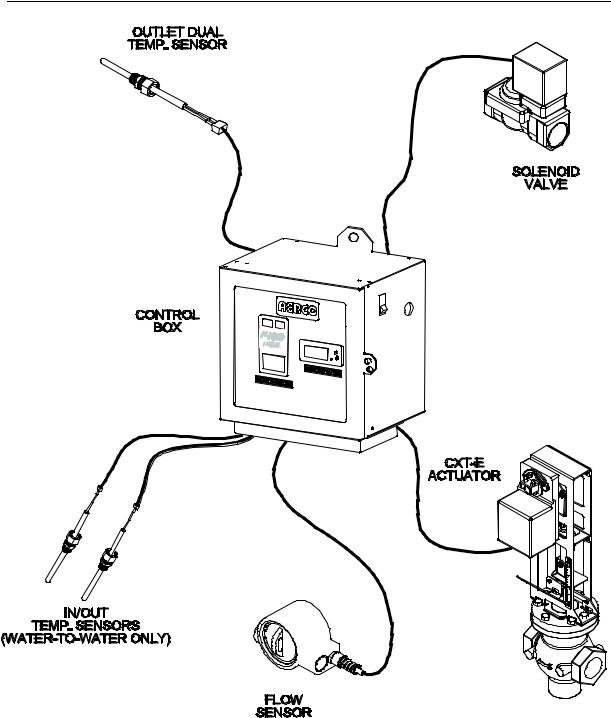
The Electronic Control System contains a Control Box Assembly which includes all of the electronic circuitry for the ECS. In addition, the ECS includes several sensors and safety devices which provide temperature and flow control information to the Control Box circuitry. The Control Box and the additional devices included in the ECS are shown in Figure 1-2. The additional devices included in the ECS include:
•Feed-Forward Flow Sensor (Flowmeter)
•Outlet Dual Temperature Sensors (Type J Thermocouples)
•Heating Fluid Inlet/Outlet Temperature Sensors (Type J Thermocouples) – For Water-to- Water Heat Exchangers Only
•Over-Temperature Solenoid Valve
If desired, the Electronic Control System (ECS) can be ordered with a Modbus Communication Option. This option permits the ECS to be externally controlled by an Energy Management System (EMS), Building Automation System (BAS), or Computer supplied by other manufacturers.
A Gateway option exists to link with other communication protocols. Check with your AERCO sales representative for more information.
The Electronic Control System assemblies and components are described in the following paragraphs.
VD2: 02/28/14 |
AERCO International, Inc. • 100 Oritani Dr. • Blauvelt, New York 10913 • Phone: 800-526-0288 |
Page 7 of 82 |
AC-105 |
|
OMM-0003_0D |
 User Manual")
Electronic Control System (ECS) and Type CXT-E Valve
1. GENERAL INFORMATION
Figure 1-1. Typical ECS & CXT-E Installation With a Packaged Water Heater
Page 8 of 82 AERCO International, Inc. •100 Oritani Dr. • Blauvelt, New York 10913 •Phone: 800-526-0288 |
VD2: 02/28/14 |
OMM-0003_0D |
AC-105 |
Electronic Control System (ECS) and Type CXT-E Valve
1.GENERAL INFORMATION
Figure 1-2. Electronic Control System (ECS)
1.2.1 Control Box Assembly
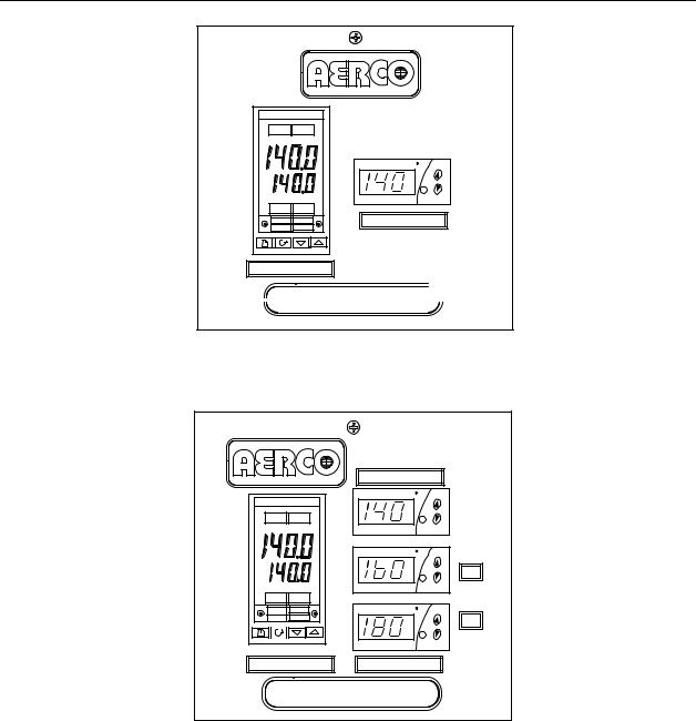
The Control Box Assembly is available in two models; one for Steam-to-Water Heaters and one for Water-to-Water Heaters. The only difference between these two models are the Display devices provided on the front panels. The panel of the Control Box model for Water-to-Water applications contain two additional Display devices which display the heating fluid (hot boiler water) inlet and outlet temperatures. The Control Box front panels for both models are shown in Figure 1-3.
VD2: 02/28/14 |
AERCO International, Inc. • 100 Oritani Dr. • Blauvelt, New York 10913 • Phone: 800-526-0288 |
Page 9 of 82 |
AC-105 |
|
OMM-0003_0D |
Electronic Control System (ECS) and Type CXT-E Valve
1. GENERAL INFORMATION
|
2408 |
OP 1 |
OP 2 |
SP2 |
REM |
AUTO |
RUN |
MAN |
HOLD |
TEMP CONTROLLER
F
SET
OVER TEMP SWITCH


 B-PLUS WATER HEATER

MODEL 69012-1
FRONT PANEL FOR STEAM-TO-WATER HEATERS
|
|
OVER TEMP SWITCH |
|
|
F |
|
2408 |
|
OP 1 |
OP 2 |
SET |
|
|
F |
|
|
OUT |
|
|
SET |
SP2 |
REM |
|
AUTO |
RUN |
F |
MAN |
HOLD |
IN |
|
|
|
|
|
SET |
TEMP CONTROLLER |
BOILER WATER TEMP |
|
E-PLUS WATER HEATER |
||
MODEL 69012-2
FRONT PANEL FOR WATER-TO-WATER HEATERS
Figure 1-3. ECS Control Box Models Showing Front Panel Differences
The Control Box is the heart of the ECS. It contains the Temperature Controller, an OverTemperature Switch and, when required, Inlet/Outlet Temperature Indicators for Water-to-Water applications. The Temperature Controller is the “brain” of the ECS which processes data received from the temperature and flow sensors. Using PID (Proportional Integral Derivative) algorithms, the Temperature Controller provides a 4-to-20 mA control signal to the Control Valve Actuator which precisely modulates the Control Valve for optimum outlet temperature control.
Page 10 of 82 AERCO International, Inc. • 100 Oritani Dr. • Blauvelt, New York 10913 • Phone: 800-526-0288 |
VD2: 02/28/14 |
OMM-0003_0D |
AC-105 |
Electronic Control System (ECS) and Type CXT-E Valve
1.GENERAL INFORMATION
An Over-Temperature Switch is also included in the Control Box to constantly monitor the Water Heater outlet temperature to ensure the Heater does not exceed the preset high temperature limit. Typically, the over-temperature limit is set 20°F above the desired Heater setpoint temperature. If an over-temperature condition occurs, this Switch sounds an audible alarm, activates the Over-Temperature Solenoid and cuts off power to the Control Valve Actuator. This closes the Control Valve and shuts off the heating fluid (steam or hot boiler water) to the Heater. In addition, activation of the Over-Temperature Solenoid allows over-temperature water to be dumped from the Heater shell.
The Control Box also contains a DC Power Supply and Voltage Regulator to provide the voltage levels required by the ECS Control Box circuitry, flow sensor and safety devices. It also provides 24 VDC power to the Control Valve CXT-E Actuator.
The Control Box components are housed in a steel enclosure with a hinged front door. This door contains a clear polycarbonate window which permits maintenance personnel to view the controls and displays of the Temperature Controller, and other display devices mounted on a recessed panel behind the door. All sensor and control signal connections are made via cable connections at the bottom of the Control Box. External AC power (120 to 240 VAC, 50/60 Hz) is supplied via a cutout on the right side of the Control Box.
1.2.2 Feed-Forward Flow Sensor
The Feed-Forward Flow Sensor is installed between the cold water inlet and the drain valve on the Water Heater as shown in Figure 1-1. The Flow Sensor monitors a portion of the inlet flow to the Heater and provides a feed-forward signal to the Temperature Controller which is proportional to the change in flow through the Heater.
1.2.3 Outlet Temperature Sensors
The Control System includes a Dual Temperature Sensor which is installed in the hot water outlet of the Water Heater. This sensor contains two identical Type J thermocouples. The first thermocouple connects directly to the Temperature Controller in the Control Box to provide the outlet water temperature. The second thermocouple connects to the Over-Temperature Switch in the Control Box.
1.2.4 Heating Fluid Inlet/Outlet Temperature Sensors
When the Heater utilizes hot (boiler) water as the heating fluid, two additional Temperature Sensors (Type J thermocouples) are provided with the Control System. One temperature Sensor is installed at the heating fluid inlet and the other is installed at the heating fluid outlet. These two Sensors are connected to two identical Temperature Display Indicators in the Control Box to provide real-time indications of the inlet and outlet heating fluid temperatures. These Temperature Indicators are physically identical to the Over-Temperature Switch, however they are “Indicator-Only” devices and do not provide any switching functions.
1.2.5 Over-Temperature Solenoid Valve
As previously mentioned, the Over-Temperature Solenoid Valve operates in conjunction with the Over-Temperature Switch in the Control Box. An over-temperature alarm is activated when the preset high temperature limit is exceeded, thereby energizing and opening the Solenoid Valve. This allows over-heated water and pressure build-up to be expelled from the Heater Shell and relieve pressure build-up.
VD2: 02/28/14 |
AERCO International, Inc. • 100 Oritani Dr. • Blauvelt, New York 10913 • Phone: 800-526-0288 |
Page 11 of 82 |
AC-105 |
|
OMM-0003_0D |

Electronic Control System (ECS) and Type CXT-E Valve
1.GENERAL INFORMATION
1.3ELECTRONIC CONTROL VALVE CXT-E
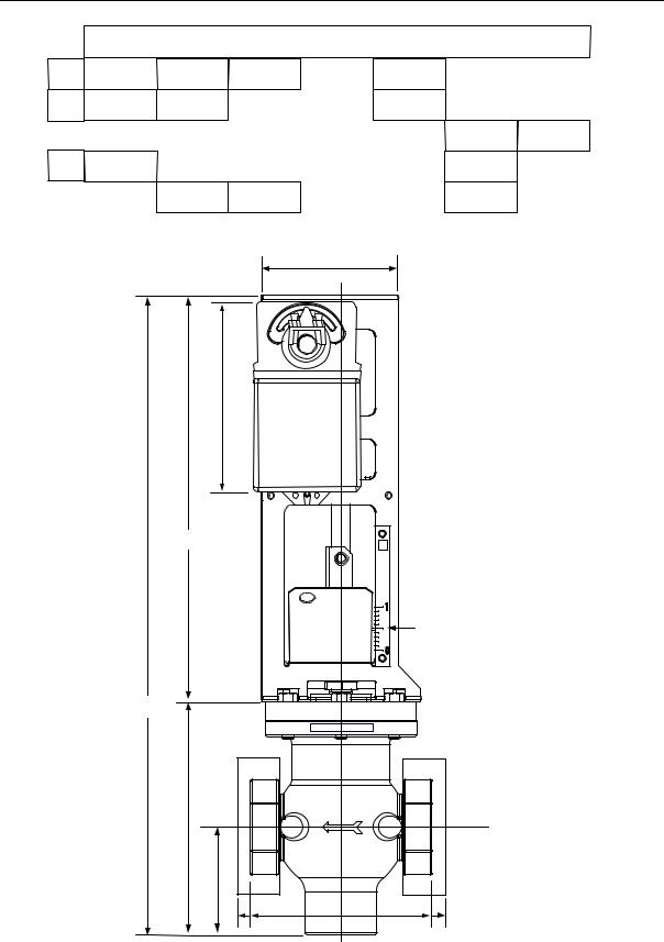
Each Control Valve is comprised of three major sections; the Valve Body, Linkage Assembly and the Valve Actuator. The Control Valves are available in sizes ranging from 1 inch to 4 inches. An identical Actuator Assembly is used with each size Valve Body. The Linkage Assembly used with each size Valve Body is identical, except for minor differences in the Shaft Adapter stroke of the mechanical linkage. Figure 1-4 shows the basic dimensions for each size AERCO Control Valve CXT-E.
It should be noted that the Control Valves used for steam flow are identical to those used for hot (boiler) water flow.
1.3.1 Control Valve Accessories
The accessories required for use with AERCO Electronic Control Valves, Type CXT-E will depend on the specific application. Detailed installation instructions, including typical installation drawings are provided in the INSTALLATION Section of this manual. However, please note the items listed below and ensure that ALL mandatory items are available:
ACCESSORY
•Upstream Shutoff Valve
•Downstream Shutoff Valve
•Strainer and Blow-Off Valve
•High Side Pressure Gauge
•Low Side Pressure Gauge, Compound Type for steam flow
REQUIREMENT
- Mandatory
Suggested for ease of maintenance. Required if a Bypass Line is used.
Mandatory
Recommended for adjustment and maintenance
Recommended for adjustment and maintenance.
If any of these items have been furnished by AERCO with the Control Valve, the necessary drawings and/or instructions should be included with the shipment.
Page 12 of 82 AERCO International, Inc. • 100 Oritani Dr. • Blauvelt, New York 10913 • Phone: 800-526-0288 |
VD2: 02/28/14 |
OMM-0003_0D |
AC-105 |
Electronic Control System (ECS) and Type CXT-E Valve
1.GENERAL INFORMATION
|
|
|
VALVE SIZES (INCHES) |
|
|
||
DIM. |
1.00" |
1.25" |
1.50" |
2.00" |
2.50" |
3.00" |
4.00" |
A |
21.12 |
21.12 |
21.12 |
24.25 |
24.25 |
24.25 |
24.25 |
B |
7.75 |
7.75 |
7.75 |
7.75 |
10.87 |
10.87 |
10.87 |
C |
3.56 |
3.56 |
3.56 |
3.56 |
6.38 |
6.38 |
6.38 |
D |
6.00 |
6.00 |
6.00 |
6.00 |
10.87 |
10.87 |
10.87 |
|
|
|
|
4.50" |
|
|
|
|
|
6.60" |
|
|
|
|
|
|
|
13.375 |
|
|
|
|
|
|
|
|
|
|
POSITION |
|
|
|
|
|
|
|
SCALE |
|
|
|
|
A |
|
|
|
|
|
|
|
B |
|
|
|
|
|
|
|
|
C |
|
|
|
|
|
|
|
D |
|
|
|
|
Figure 1-4. Reference Dimensions for AERCO Control Valves, Type CXT-E
VD2: 02/28/14 |
AERCO International, Inc. • 100 Oritani Dr. • Blauvelt, New York 10913 • Phone: 800-526-0288 |
Page 13 of 82 |
AC-105 |
|
OMM-0003_0D |

Electronic Control System (ECS) and Type CXT-E Valve
1.GENERAL INFORMATION
1.4REFERENCE DOCUMENTS
Refer to the following documents as necessary for additional information and procedures for the applicable AERCO Heat Exchanger provided with your Electronic Control System (ECS) and CXT-E Control Valve. In addition, if the ECS is provided with the Modbus Communication option, refer to the referenced Eurotherm documents listed.
1.4.1 AERCO Documents
HE-104 SW1B-Plus Heat Exchanger Installation, Operation & Maintenance Manual HE-105 WW3E Heat Exchanger Installation, Operation & Maintenance Manual
HE-106 DW-24, DW-45, DW-68 Double Wall Heat Exchanger Installation, Operation &
Maintenance Manual
HE-107 SW1A-Plus Heat Exchanger Installation, Operation & Maintenance Manual
HE-110 B-Plus II Water Wizard Heat Exchanger Installation, Operation & Maintenance
Manual
1.4.2 Eurotherm Documents – (Available at www.eurotherm.com)
HA025132 2404/2408 Installation & Operation Handbook HA02630 Series 2000 Communications Handbook
!CAUTION !
DO NOT use the Actuator Linkage Frame at the top of the Control Valve Body for leverage when installing The Control Valve. Use pipe wrenches on the inlet and outlet hex of the Valve Body.
Page 14 of 82 AERCO International, Inc. • 100 Oritani Dr. • Blauvelt, New York 10913 • Phone: 800-526-0288 |
VD2: 02/28/14 |
OMM-0003_0D |
AC-105 |

Electronic Control System (ECS) and Type CXT-E Valve
2.INSTALLATION
2.INSTALLATION
2.1INTRODUCTION
Normally, the Electronic Control System (ECS) is shipped already installed on the Packaged Water Heater. However, the Control Valve, Type CXT-E is packed separately. For smaller size Valves (1” to 2”), the packaged Valve is attached to the base of the shipping crate. For larger size Valves (2 ½” to 4”), the packaged Valve may be shipped separately due to space limitations within the Heater shipping crate. Therefore, the installation procedures consist basically of:
•Installing the Electronic Control Valve, Type CXT-E and associated steam or hot (boiler) water piping and components.
•Connecting external power to the ECS Control Box
•Connecting and checking electrical connections to the CXT-E Actuator and other ECS components
IMPORTANT NOTE!
For Water-to-Water Double-Wall (WWDW) heaters equipped with the ECS, the following minimum recirculation flow must be provided to achieve ±4°F temperature control under normal diversified domestic load conditions:
Double-Wall Model |
Minimum System Recirculation |
|
|
WWDW24 |
10 gpm |
|
|
WWDW45 |
15 gpm |
|
|
WWDW68 |
20 gpm |
|
|
2.2ELECTRONIC CONTROL VALVE TYPE CXT-E INSTALLATION
The following procedures apply to all sizes of AERCO Electronic Control Valves Type CXT-E ranging from 1 inch to 4 inches. In addition, the following steps can be used for both steam and hot (boiler) water flow systems. Proceed as follows:
1)Refer to Figure 1-3 for dimensions of the Control Valve furnished with the Packaged Water Heater.
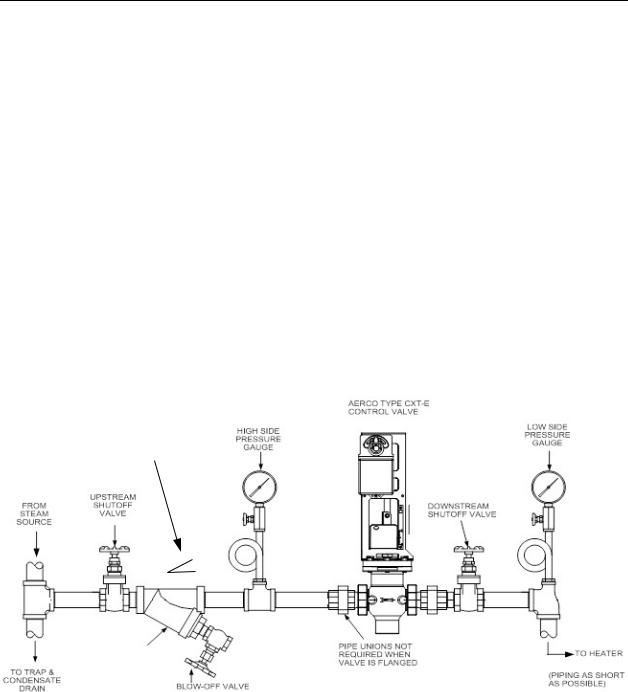
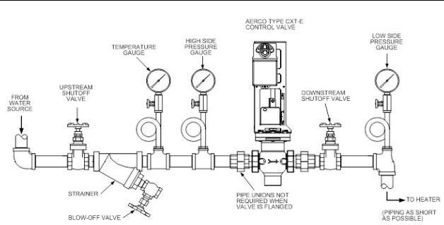
2)Next, refer to the recommended installation drawing in Figure 2-1 for steam flow, or Figure 2-2 for hot (boiler) water flow.
3)Install the Control Valve with the Actuator Linkage in the vertical, upright position as shown in Figure 2-1 or 2-2.
4)For maintenance purposes, unions are required with threaded ends to simplify removal from the steam or hot boiler water line.
5)Blow out all pipe lines to clear them of dirt chips, scale or other foreign matter which could adversely affect Valve operation when in service.
6)Install an in-line strainer upstream of the Valve as shown in Figure 2-1 (steam) or Figure 2- 2 (hot boiler water). This will protect against foreign matter reaching the Valve during service operation.
VD2: 02/28/14 |
AERCO International, Inc. • 100 Oritani Dr. • Blauvelt, New York 10913 • Phone: 800-526-0288 |
Page 15 of 82 |
AC-105 |
|
OMM-0003_0D |
Electronic Control System (ECS) and Type CXT-E Valve
2.INSTALLATION
7)If the Valve is controlling steam, ensure that the steam line is properly trapped to prevent accumulation of condensate ahead of the Valve.
8)Install Shutoff Valves (metal-seated, gate-type) upstream and downstream of the Control Valve to permit removal from the line for maintenance.
9)Pressure gauges should be installed on both sides of the Control Valve as shown in Figure 2-1 (steam) or Figure 2-2 (hot water).
10)The gauge on the high pressure side of the Valve is for adjustment and maintenance purposes. The gauge on the low pressure side is to ensure that the correct pressure is being introduced to the Control Valve. For either steam or water flow, the low side gauge denotes the pressure of the fluid in the line which may create a hazardous condition.
11)A temperature gauge should be installed in the high pressure side of a hot (boiler) water line as shown in Figure 2-2.
12)Install the Control Valve with the arrow on the Valve Body pointing in the direction of flow.
13)After the Control Valve has been installed in the steam or hot water line, ensure that all piping connections are secure and leak tight.
14)This completes the installation procedures for the Control Valve. Proceed to the next paragraph titled ELECTRONIC CONTROL SYSTEM INSTALLATION.
PIPING PITCH DIRECTION 1 TO 40 RATIO MINIMUM
STRAINER WITH 0.020
MEST STAINLESS
STEEL BASKET,
SHOWN ROTATED
DOWN 90 DEGREES
FOR CLARITY
Figure 2-1. Recommended Control Valve, CXT-E Installation For Steam Flow
Page 16 of 82 AERCO International, Inc. • 100 Oritani Dr. • Blauvelt, New York 10913 • Phone: 800-526-0288 |
VD2: 02/28/14 |
OMM-0003_0D |
AC-105 |
Electronic Control System (ECS) and Type CXT-E Valve
2. INSTALLATION
Figure 2-2. Recommended Control Valve, CXT-E Installation For Hot (Boiler)
Water Flow
2.3ELECTRONIC CONTROL SYSTEM (ECS) INSTALLATION
As previously mentioned, the Control Box and all other Electronic Control System (ECS) components are installed on the Packaged Water Heater prior to shipment from the factory. Therefore, ECS installation basically consists of connecting external AC power to the System and providing the necessary power and control signal connections to the Control Valve Type CXT-E. However, if your ECS was ordered with the Modbus Communication option, several additional signal lead connections will need to be made inside the Control Box. These signal leads will permit the ECS to be controlled by an external Energy Management System (EMS), Building Automation System (BAS), or Computer.
NOTE:
Following installation, a lock (Not Supplied) can be installed on the front door of the Control Box, if desired, to prevent unauthorized access to ECS settings.
VD2: 02/28/14 |
AERCO International, Inc. • 100 Oritani Dr. • Blauvelt, New York 10913 • Phone: 800-526-0288 |
Page 17 of 82 |
AC-105 |
|
OMM-0003_0D |
Electronic Control System (ECS) and Type CXT-E Valve
2.INSTALLATION
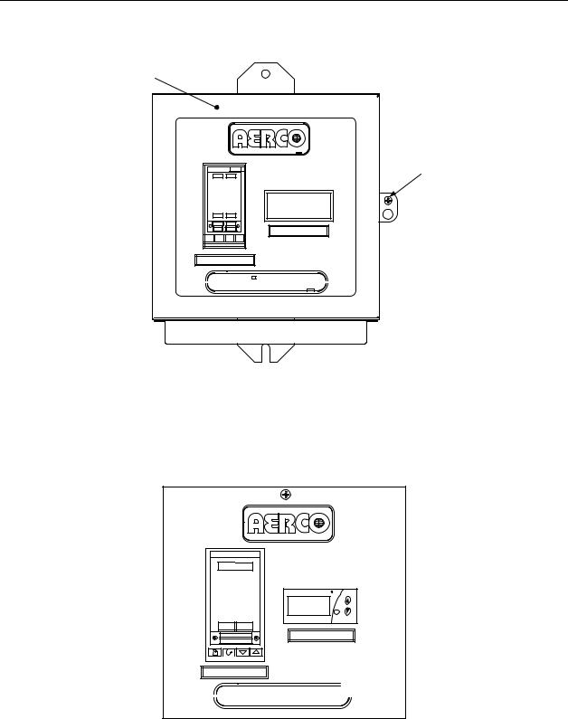
1)Loosen the captive screw on the right-front portion of the Control Box (Figure 2-3) to open the hinged panel door.
PANEL
DOOR
|
CAPTIVE |
2408 |
SCREW |
AUTO RUN |
|
MAN HOLD |
OVER TEMP SWITCH |
|
TEMP CONTROLLER

 B-PLUS TM WATER HEATER

PT.NO.
Figure 2-3. ECS Control Panel Front View
2)Next, open the door and loosen the captive screw at the top of the recessed panel (Figure 2-4). Swing down the recessed panel to access Terminal Block TB-2 on the bottom interior surface of the Control Box shown in Figure 2-5.
PANEL CAPTIVE
SCREW 
2408
OP 1 
 OP 2
OP 2
SP2 REM
AUTO 
 RUN
RUN
MAN 
 HOLD
HOLD
TEMP CONTROLLER
F
SET
OVER TEMP SWITCH

 B-PLUS WATER HEATER

Figure 2-4. Recessed Panel Behind Control Box Door
3)Feed the external 120/240 VAC power leads through the cutout labeled “POWER IN” on the right side of the Control Box.
Page 18 of 82 AERCO International, Inc. • 100 Oritani Dr. • Blauvelt, New York 10913 • Phone: 800-526-0288 |
VD2: 02/28/14 |
OMM-0003_0D |
AC-105 |
Electronic Control System (ECS) and Type CXT-E Valve
2.INSTALLATION
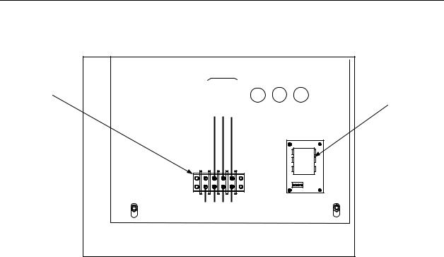
4)Connect the LINE, NEUTRAL and GROUND leads to the TB-2 terminals shown in Figure 2- 5.
TERMINAL BLOCK TB-2
REAR |
|
||
EXTERNAL POWER WIRING |
|
||
(120 – 240 VAC) |
|
||
|
NEUTRAL |
GROUND |
VOLTAGE |
LINE |
REGULATOR |
||
|
|||
TB-2 |
|
|
|
100 101 |
102 |
GND |
|
FRONT |
|
||
CONTROL BOX - INTERIOR BOTTOM VIEW
Figure 2-5. ECS Control Box AC Power Connections
5)Connect the Control Box cable labeled ACTUATOR to the 3-pin connector plug on the Control Valve Actuator.
6)Check to ensure that all cable harness connectors and wire leads between the Control Box and the following ECS components are secure:
a)Flow Sensor
b)Over-Temperature Solenoid
c)Outlet Dual Temperature Sensor
d)Heating Fluid Inlet/Outlet Temperature Sensors (Water-to-Water Heaters Only)
7)If the ECS was ordered with the Modbus Communication Option, proceed to step 8. However, if this option is not included, no further steps are required for ECS installation.
NOTE:
Step 8 applies ONLY to Electronic Control Systems which include a Temperature Controller (Eurotherm, Model 2408) equipped with a Communications Board which allows connection to Modbus Networks. The required signal connections will depend on the ports available on the Energy Management System (EMS), Building Automation System (BAS), or Computer being used with the ECS.
VD2: 02/28/14 |
AERCO International, Inc. • 100 Oritani Dr. • Blauvelt, New York 10913 • Phone: 800-526-0288 |
Page 19 of 82 |
AC-105 |
|
OMM-0003_0D |

Electronic Control System (ECS) and Type CXT-E Valve
2. INSTALLATION
CAUTION!
DO NOT route Modbus communication wiring in the same conduit as power wiring. Attempting to do so may result in excessive noise on the signal lines. Also, ensure that the RS232 or RS485 signal cable connections do not exceed the following lengths:
RS232 Cable: 50 feet maximum RS485 Cable: 4,000 feet maximum
8)To permit Modbus control of the ECS, refer to Table 2-1 and connect the appropriate wire leads to the Temperature Controller terminals listed. Refer to the Temperature Controller (Eurotherm 2408) pinouts shown in Figure 2-6 to locate the required terminals. Also, refer to Appendix A for a listing of active Modbus data addresses for the 2408 Controller. In addition, the Eurotherm documents referenced in this Appendix provide additional communication information related to Modbus.
NOTE:
The complete wiring diagram for the Electronic Control System is provided in Appendix B of this Instruction Manual. In addition, the wiring connections for Terminal Blocks TB-1 and TB-2 are provided for reference purposes.
NOTE:
AERCO recommends that shielded, twisted-pair cable be used for communication wiring. Examples of suitable wiring are: Belden 9841, 8761, 3105A, or equivalent.
Table 2-1. Modbus Communication Signal Connections
|
|
COMPUTER CONTROL CABLE |
|
||
2408 TEMP. CONTROLLER |
|
|
|
|
|
|
RS232/9-PIN |
RS232/25-PIN |
RS485 |
||
|
|
|
|
|
|
SIGNAL NAME |
PIN NO. |
SIGNAL NAME |
PIN NO. |
PIN NO. |
PIN NO. |
|
|
|
|
|
|
GROUND |
HD |
GROUND |
5 |
7 |
GROUND |
|
|
|
|
|
|
RECEIVE |
HE |
TRANSMIT |
3 |
2 |
A (-) |
|
|
|
|
|
|
TRANSMIT |
HF |
RECEIVE |
2 |
3 |
B (+) |
|
|
|
|
|
|
Page 20 of 82 AERCO International, Inc. • 100 Oritani Dr. • Blauvelt, New York 10913 • Phone: 800-526-0288 |
VD2: 02/28/14 |
OMM-0003_0D |
AC-105 |
Electronic Control System (ECS) and Type CXT-E Valve
2. INSTALLATION
2408 CONTROLLER
1A |
HA L |
|
|
1B |
HB N |
|
|
1C |
HC |
|
|
1D |
HD LA |
In1 |
|
2A |
HE LB |
||
In2 |
|||
2B |
HF LC |
||
|
|||
2C |
JA AA |
C |
|
2D |
JB AB |
||
3A |
JC AC |
|
|
3B |
JD VI |
|
|
3C |
JE V+ |
|
|
3D |
JF V- |
|
SEE TABLE 2-1 FOR COMM CONNECTIONS
Figure 2-6. Temperature Controller (Eurotherm 2408) Terminal Connection
Diagram
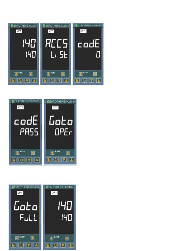
2.4CHANGING COMMUNICATION ADDRESSES ON AERCO EUROTHERM TEMPERATURE CONTROLLER
The address is defaulted to 1 from the factory. Refer to the Button map below for all panel
navigation instructions.
Button Map
Page |
Scroll |
Down |
UP |
|
|
Arrow |
Arrow |
VD2: 02/28/14 |
AERCO International, Inc. • 100 Oritani Dr. • Blauvelt, New York 10913 • Phone: 800-526-0288 |
Page 21 of 82 |
AC-105 |
|
OMM-0003_0D |
Electronic Control System (ECS) and Type CXT-E Valve
2. INSTALLATION
To change the modbus address:
1) Page to the ACCS list and Scroll down the list to codE.
2) Enter 24 using the Up Arrow. The number will display and flash PASS.
3)Scroll to Goto (current value is OPEr) and use the Down Arrow to enter a value of Full. The entry is confirmed by the flashing of the lower display momentarily off and then on.
Page 22 of 82 AERCO International, Inc. • 100 Oritani Dr. • Blauvelt, New York 10913 • Phone: 800-526-0288 |
VD2: 02/28/14 |
OMM-0003_0D |
AC-105 |
Electronic Control System (ECS) and Type CXT-E Valve
2.INSTALLATION
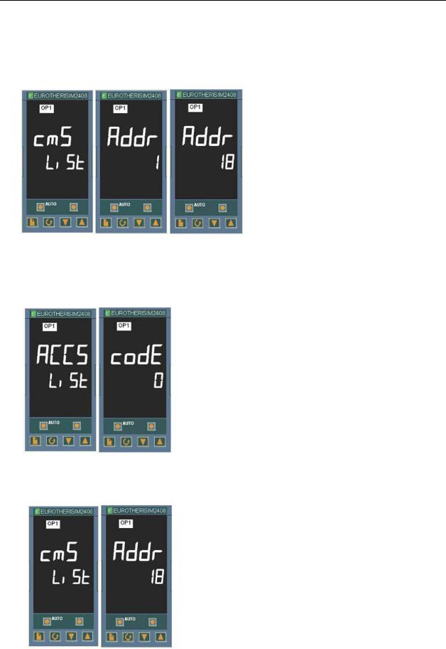
4)Go to the home screen by pressing the Page and Scroll buttons at the same time.
5)Page to the cmS list.
6)Scroll to the Addr screen
7)Use the Up Arrow to select the desired address number.
8)Go to the home screen by pressing the Page and Scroll buttons at the same time.
9)Page to the ACCS List and change the code to anything other than 24. The codE number you have entered will flash off and then on to 0 to confirm that access is now set to OPEr level and it is safe to return to use.
10)Confirm that the Addr is set properly by pressing Page button until the cmS list is displayed and Scroll to Addr. If the value is correct, you are done. If not, then repeat the steps over again.
VD2: 02/28/14 |
AERCO International, Inc. • 100 Oritani Dr. • Blauvelt, New York 10913 • Phone: 800-526-0288 |
Page 23 of 82 |
AC-105 |
|
OMM-0003_0D |

Electronic Control System (ECS) and Type CXT-E Valve
2.INSTALLATION
2.5ENABLING REMOTE SETPOINT CONFIGURATION ON THE AERCO EUROTHERM TEMPERATURE CONTROLLER
The setpoint may be programmed to be remotely configured by executing the following steps. See the previous instructions for changing communication addresses in the AERCO Eurotherm Temperature Controller for more detailed directions for programming the controller.
1)Page to “ACCS”.
2)Scroll and enter code of 1.
3)Scroll and at the “GOTO” menu choose “Conf”.
4)At the “Conf” screen enter the code of 2
5)Press the Scroll button once and then the Page button until you find “SP”.
6)Scroll until you find “rmt” and set the parameter value to “SP”.
7)Press the Page and Scroll button together at the same time to go to “exit”.
8)Press the Up arrow to select “yes” and then the instrument will reboot.
9)Once the instrument has returned to its normal state, press the Page button until you see “SP”.
10)Scroll until you see “L-r” and using the Up arrow select “rmt”.
11)Once you have selected “rmt” press the Page and Scroll buttons at the same time to return to the normal temp display.
You should now be able to control the set point remotely.
Page 24 of 82 AERCO International, Inc. • 100 Oritani Dr. • Blauvelt, New York 10913 • Phone: 800-526-0288 |
VD2: 02/28/14 |
OMM-0003_0D |
AC-105 |

Electronic Control System (ECS) and Type CXT-E Valve
3.ADJUSTMENT
3.ADJUSTMENT
3.1INTRODUCTION
This Section provides adjustment procedures for both the Control Valve, Type CXT-E and the Electronic Control System (ECS).
Prior to shipment, from AERCO, all CXT-E Control Valve Actuators are adjusted (auto-stroked) to ensure that they properly position the Control Valve from the fully-open to the fully-closed positions. In addition, the ECS is adjusted to the Setpoint Temperature specified on the Sales Order. If no setting was specified, the default is 140°F.
It is recommended that the following procedures be performed to the extent necessary, prior to placing the system into operation. Also, the applicable procedures MUST be performed following replacement of the CXT-E Control Valve or other ECS components. In addition, the following procedure must be performed following maintenance or adjustment of linkage, actuator or packing nut.
!CAUTION !
As a precaution, ensure that all heating fluid (steam or hot (boiler) water) shutoff valves are fully closed prior to performing any of the following adjustment procedures.
3.2CONTROL VALVE TYPE CXT-E ADJUSTMENT
All CXT-E Actuators are powered by 24 VDC and are controlled by a linear 4-to-20 mA control signal. A 4 mA control signal input places the Control Valve in the fully-closed position(Valve shaft down); while a 20 mA signal strokes the Valve to the fully-open position (Valve shaft up).
The Control Valve Actuators are self-calibrating for all Valve sizes. Therefore, simply proceed as follows to automatically adjust the Actuator:
NOTE:
The following adjustment procedure must be performed any time that the CXT-E Actuator is replaced or a mechanical adjustment is made to the Linkage Assembly or Valve.
1)Refer to Figure 3-1 and loosen the Actuator cover set screw.
2)Remove the Actuator cover to access the PC Board containing the terminal connections, DIP switches, Auto-Stroke (Reset) button and LED shown in Figure 3-1.
NOTE:
When properly connected to the ECS, +24 VDC power is supplied to the Control Valve Actuator when the Control Box POWER switch is set to the ON position. This switch is located on the right side of the Control Box.
3)Set the ECS Control Box POWER switch to the ON position to apply 24 VDC power to the Actuator (pin 2 = +24 VDC, pin 1 = Common). The LED will light indicating that power is applied.
4)Wait approximately 10 seconds while the unit performs a self-test. The LED will blink from one to four times depending on the size of the valve as follows:
VD2: 02/28/14 |
AERCO International, Inc. • 100 Oritani Dr. • Blauvelt, New York 10913 • Phone: 800-526-0288 |
Page 25 of 82 |
AC-105 |
|
OMM-0003_0D |
Loading...