


 Loading...
Benchmark 6000 Boiler Installation, Operation & Maintenance Manual
Natural Gas Modulating & |
USER MANUAL |
|
Installation, Operation and Maintenance |
||
Condensing Hot Water Boiler |
|
|
Applicable to Serial Numbers: |
BENCHMARK 6000 |
|
Gas-Fired Boiler |
||
N-14-0172 and Above |
||
|
Latest Update: 03/20/14
OMM-0086_0D |
AERCO International, Inc. •100 Oritani Dr. • Blauvelt, NY 10913 |
Page 1 of 210 |
GF-133 |
Ph.: 800-526-0288 |
03/20/14 |

Benchmark 6000 Boiler Installation, Operation & Maintenance Manual
Technical Support (Mon-Fri, 8am-5pm EST)
1-800-526-0288 www.aerco.com
Disclaimer
The information contained in this manual is subject to change without notice from AERCO International, Inc. AERCO makes no warranty of any kind with respect to this material, including but not limited to implied warranties of merchantability and fitness for a particular application. AERCO International is not liable for errors appearing in this manual. Nor for incidental or consequential damages occurring in connection with the furnishing, performance, or use of this material.
Page 2 of 210 |
AERCO International, Inc. •100 Oritani Dr. • Blauvelt, NY 10913 |
OMM-0086_0D |
03/20/14 |
Ph.: 800-526-0288 |
GF-133 |

Benchmark 6000 Boiler Installation, Operation & Maintenance Manual
|
TABLE OF CONTENTS |
|
FOREWORD .......................................................................................................................................... |
7 |
|
CHAPTER 1. |
SAFETY PRECAUTIONS................................................................................................ |
11 |
1.1 WARNINGS & CAUTIONS ..................................................................................................................................... |
11 |
|
1.2 EMERGENCY SHUTDOWN.................................................................................................................................... |
12 |
|
1.3 PROLONGED SHUTDOWN ................................................................................................................................... |
13 |
|
1.4 MASSACHUSETTS INSTALLATIONS ............................................................................................... |
13 |
|
CHAPTER 2. |
INSTALLATION ............................................................................................................... |
15 |
2.1 INTRODUCTION ................................................................................................................................................... |
15 |
|
2.2 RECEIVING THE UNIT ........................................................................................................................................... |
15 |
|
2.3 MOVING & UNPACKING THE UNIT ...................................................................................................................... |
15 |
|
2.4 SITE PREPARATION .............................................................................................................................................. |
16 |
|
2.4.1 Installation Clearances ................................................................................................................................. |
16 |
|
2.4.2 Setting the Unit ............................................................................................................................................ |
18 |
|
2.5 SUPPLY AND RETURN PIPING .............................................................................................................................. |
19 |
|
2.6 PRESSURE RELIEF VALVE & PRESSURE/TEMPERATURE INDICATOR INSTALLATION............................................ |
20 |
|
2.6.1 Pressure Relief Valve Installation ................................................................................................................. |
20 |
|
2.6.2 Pressure/Temperature Gauge Installation ................................................................................................... |
21 |
|
2.7 CONDENSATE DRAIN & PIPING............................................................................................................................ |
22 |
|
2.8 GAS SUPPLY PIPING ............................................................................................................................................. |
23 |
|
2.8.1 Gas Supply Specifications ............................................................................................................................. |
24 |
|
2.8.2 Manual Gas Shutoff Valve ............................................................................................................................ |
24 |
|
2.8.3 External Gas Supply Regulator ..................................................................................................................... |
24 |
|
2.8.3.1 Massachusetts Installations Only .......................................................................................................... |
24 |
|
2.8.3.2 All Installations (Except Massachusetts) ............................................................................................... |
24 |
|
2.9 AC ELECTRICAL POWER WIRING.......................................................................................................................... |
25 |
|
2.9.1 Electrical Power Requirements .................................................................................................................... |
27 |
|
2.10 FIELD CONTROL WIRING.................................................................................................................................... |
27 |
|
2.10.1 OUTDOOR AIR IN Terminal......................................................................................................................... |
29 |
|
2.10.2 COMBUSTION AIR Terminal ....................................................................................................................... |
30 |
|
2.10.3 O2 SENSOR Terminals ................................................................................................................................. |
30 |
|
2.10.4 SPARK SIGNAL Terminals ............................................................................................................................ |
30 |
|
2.10.5 ANALOG IN Terminals................................................................................................................................. |
30 |
|
2.10.6 B.M.S. (PWM) IN Terminals ........................................................................................................................ |
30 |
|
2.10.7 SHIELD Terminals........................................................................................................................................ |
30 |
|
2.10.8 ANALOG OUT Terminals ............................................................................................................................. |
30 |
|
2.10.9 RS485 Comm Terminals.............................................................................................................................. |
31 |
|
2.10.10 RS232 Comm Terminals............................................................................................................................ |
31 |
|
2.10.11 VFD/BLOWER Terminals ........................................................................................................................... |
31 |
|
2.10.12 Interlock Terminals................................................................................................................................... |
31 |
|
2.10.12.1 Remote Interlock In (OUT & IN)......................................................................................................... |
31 |
|
2.10.12.2 Delayed Interlock In (OUT & IN) ........................................................................................................ |
31 |
|
2.10.13 FAULT RELAY Terminals............................................................................................................................ |
32 |
|
2.10.14 AUX.RELAY Terminals ............................................................................................................................... |
32 |
|
2.11 FLUE GAS VENT INSTALLATION ......................................................................................................................... |
32 |
|
2.12 COMBUSTION AIR.............................................................................................................................................. |
33 |
|
2.12.1 Combustion From Outside the Building ..................................................................................................... |
33 |
|
2.12.2 Combustion Air from Inside the Building ................................................................................................... |
33 |
|
2.13 DUCTED COMBUSTION AIR ............................................................................................................................... |
34 |
|
2.14 SEQUENCING VALVE INSTALLATION.................................................................................................................. |
34 |
|
CHAPTER 3. |
OPERATION .................................................................................................................... |
37 |
3.1 INTRODUCTION ................................................................................................................................................... |
37 |
|
OMM-0086_0D |
AERCO International, Inc. •100 Oritani Dr. • Blauvelt, NY 10913 |
Page 3 of 210 |
GF-133 |
Ph.: 800-526-0288 |
03/20/14 |

Benchmark 6000 Boiler Installation, Operation & Maintenance Manual
3.2 CONTROL PANEL DESCRIPTION ........................................................................................................................... |
37 |
|
3.3 CONTROL PANEL MENUS..................................................................................................................................... |
41 |
|
3.3.1 Menu Processing Procedure......................................................................................................................... |
41 |
|
3.4 OPERATING MENU .............................................................................................................................................. |
43 |
|
3.5 SETUP MENU ....................................................................................................................................................... |
43 |
|
3.6 CONFIGURATION MENU...................................................................................................................................... |
44 |
|
3.7 TUNING MENU .................................................................................................................................................... |
46 |
|
3.8 COMBUSTION CAL MENU.................................................................................................................................... |
47 |
|
3.9 BST (Boiler Sequencing Technology ) Menu ........................................................................................................ |
47 |
|
3.10 START SEQUENCE .............................................................................................................................................. |
50 |
|
3.11 START/STOP LEVELS........................................................................................................................................... |
55 |
|
CHAPTER 4. |
INITIAL START-UP.......................................................................................................... |
59 |
4.1 INITIAL START-UP REQUIREMENTS...................................................................................................................... |
59 |
|
4.2 TOOLS AND INSTRUMENTATION FOR COMBUSTION CALIBRATION ................................................................... |
59 |
|
4.2.1 Required Tools & Instrumentation............................................................................................................... |
60 |
|
4.2.2 Installing Gas Supply Manometer................................................................................................................. |
60 |
|
4.2.3 Accessing the Analyzer Probe Port............................................................................................................... |
61 |
|
4.3 PILOT IGNITION ................................................................................................................................................... |
62 |
|
4.4 NATURAL GAS COMBUSTION CALIBRATION ....................................................................................................... |
62 |
|
4.5 REASSEMBLY AFTER COMBUSTION CALIBRATION .............................................................................................. |
67 |
|
CHAPTER 5. |
MODE OF OPERATION .................................................................................................. |
69 |
5.1 INTRODUCTION ................................................................................................................................................... |
69 |
|
5.2 INDOOR/OUTDOOR RESET MODE ....................................................................................................................... |
69 |
|
5.2.1 Reset Ratio.................................................................................................................................................... |
69 |
|
5.2.2 Building Reference Temperature ................................................................................................................. |
69 |
|
5.2.3 Outdoor Air Temperature Sensor Installation.............................................................................................. |
69 |
|
5.2.4 Indoor/Outdoor Reset Mode Startup........................................................................................................... |
69 |
|
5.3 CONSTANT SETPOINT MODE............................................................................................................................... |
70 |
|
5.3.1 Setting the Setpoint...................................................................................................................................... |
70 |
|
5.4 REMOTE SETPOINT MODES ................................................................................................................................. |
71 |
|
5.4.1 Remote Setpoint Field Wiring ...................................................................................................................... |
71 |
|
5.4.2 Remote Setpoint Startup.............................................................................................................................. |
72 |
|
5.5 DIRECT DRIVE MODES ......................................................................................................................................... |
72 |
|
5.5.1 Direct Drive Field Wiring............................................................................................................................... |
73 |
|
5.5.2 Direct Drive Startup...................................................................................................................................... |
73 |
|
5.6 AERCO CONTROL SYSTEM (ACS).......................................................................................................................... |
73 |
|
5.6.1 ACS External Field Wiring ............................................................................................................................. |
74 |
|
5.6.2 ACS Setup and Startup.................................................................................................................................. |
74 |
|
5.7 COMBINATION CONTROL SYSTEM (CCS)............................................................................................................. |
74 |
|
5.7.1 Combination Control System Field Wiring ................................................................................................... |
75 |
|
5.7.2 Combination Control System Setup and Startup.......................................................................................... |
75 |
|
CHAPTER 6. |
SAFETY DEVICE TESTING ............................................................................................ |
77 |
6.1 TESTING OF SAFETY DEVICES............................................................................................................................... |
77 |
|
6.2 LOW GAS PRESSURE FAULT TESTs ....................................................................................................................... |
77 |
|
6.3 HIGH GAS PRESSURE FAULT TEST........................................................................................................................ |
79 |
|
6.4 LOW WATER LEVEL FAULT TEST .......................................................................................................................... |
80 |
|
6.5 WATER TEMPERATURE FAULT TEST .................................................................................................................... |
81 |
|
6.6 INTERLOCK TESTS ................................................................................................................................................ |
82 |
|
6.6.1 Remote Interlock Test .................................................................................................................................. |
82 |
|
6.6.2 Delayed Interlock Test .................................................................................................................................. |
82 |
|
6.7 FLAME FAULT TESTs ............................................................................................................................................ |
82 |
|
6.8 AIR FLOW FAULT TESTS ....................................................................................................................................... |
83 |
|
6.8.1 Blower Proof Switch Test ............................................................................................................................. |
84 |
|
6.8.2 Blocked Inlet Switch Test.............................................................................................................................. |
85 |
|
Page 4 of 210 |
AERCO International, Inc. •100 Oritani Dr. • Blauvelt, NY 10913 |
OMM-0086_0D |
03/20/14 |
Ph.: 800-526-0288 |
GF-133 |

Benchmark 6000 Boiler Installation, Operation & Maintenance Manual
6.9 SSOV PROOF OF CLOSURE SWITCH ..................................................................................................................... |
87 |
|
6.10 PURGE SWITCH OPEN DURING PURGE.............................................................................................................. |
88 |
|
6.11 IGNITION SWITCH OPEN DURING IGNITION...................................................................................................... |
89 |
|
6.12 SAFETY PRESSURE RELIEF VALVE TEST............................................................................................................... |
90 |
|
CHAPTER 7. |
MAINTENANCE ............................................................................................................... |
91 |
7.1 MAINTENANCE SCHEDULE .................................................................................................................................. |
91 |
|
7.2 PILOT BURNER ..................................................................................................................................................... |
92 |
|
7.3 MAIN FLAME DETECTOR...................................................................................................................................... |
93 |
|
7.4 O2 SENSOR |
........................................................................................................................................................... |
94 |
7.5 COMBUSTION ......................................................................CALIBRATION & PILOT REGULATOR ADJUSTMENT |
95 |
|
7.5.1 Pilot Regulator ...................................................................................................................Pressure Testing |
95 |
|
7.5.2 Pilot Regulator .............................................................................................................Pressure Calibration |
97 |
|
7.6 SAFETY DEVICE ......................................................................................................................................TESTING |
98 |
|
7.7 BURNER ASSEMBLY .........................................................................................................................INSPECTION |
99 |
|
7.8 REFRACTORY ........................................................................................................REMOVAL & REPLACEMENT |
102 |
|
7.8.1 Rear Refractory ..................................................................................................Removal & Replacement |
102 |
|
7.8.2 Front Refractory .................................................................................................Removal & Replacement |
106 |
|
7.9 CONDENSATE ................................................................................................................................DRAIN TRAP |
108 |
|
7.10 AIR FILTER ..........................................................................................................CLEANING & REPLACEMENT |
109 |
|
7.11 SHUTTING .............................................................THE BOILER DOWN FOR AN EXTENDED PERIOD OF TIME |
110 |
|
7.12 PLACING THE ..................................................BOILER BACK IN SERVICE AFTER A PROLONGED SHUTDOWN |
110 |
|
CHAPTER 8. ...................................................................................... |
TROUBLESHOOTING GUIDE |
111 |
8.1 INTRODUCTION ................................................................................................................................................. |
111 |
|
8.2 ADDITIONAL ............................................................................FAULTS WITHOUT SPECIFIC FAULT MESSAGES |
124 |
|
CHAPTER 9. ........................................................................................... |
RS - 232 COMMUNICATION |
129 |
9.1 INTRODUCTION ................................................................................................................................................. |
129 |
|
9.1.1 Aquiring ..................................................................................................................the PuTTY Application |
129 |
|
9.1.2 Logging ..........................................................................................on to a Remote Machine Using PuTTY |
129 |
|
9.1.3 Running .........................................................................a Command on a Remote Machine Using PuTTY |
130 |
|
9.2 RS-232 COMMUNICATION .....................................................................................................................SETUP |
131 |
|
9.3 MENU PROCESSING ...............................................................................UTILIZING RS-232 COMMUNICATION |
131 |
|
9.4 DATA LOGGING.................................................................................................................................................. |
132 |
|
9.4.1 Fault Log ..................................................................................................................................................... |
133 |
|
9.4.2 Operation ....................................................................................................................................Time Log |
133 |
|
9.4.3 Sensor ..................................................................................................................................................Log |
134 |
|
CHAPTER 10. ......................................................................BOILER SEQUENCING TECHNOLOGY |
135 |
|
10.1 INTRODUCTION ............................................................................................................................................... |
135 |
|
10.2 AERCO BST ..........................................................................................................................Quick Start Chart |
136 |
|
10.3 BST Implementation ......................................................................................................................Instruction |
137 |
|
10.3.1 Option ............................................................1 - Constant Setpoint with DIRECT Wired Header Sensor |
137 |
|
10.3.2 Option .........................................................2 - Constant Setpoint with MODBUS Wired Header Sensor |
138 |
|
10.3.3 Option .....3 - Outdoor Reset with DIRECT WIRED Header Sensor AND DIRECT WIRED Outdoor Sensor |
139 |
|
10.3.4 Option ......................4 - Outdoor Reset with MODBUS Header Sensor AND MODBUS Outdoor Sensor |
141 |
|
10.3.5 Option ...............5 - Remote Setpoint with DIRECT WIRED Header Sensor AND 4-20ma Setpoint Drive |
143 |
|
10.3.6 Option .............6 - Remote Setpoint with DIRECT WIRED Header Sensor AND MODBUS Setpoint Drive |
144 |
|
10.3.7 Option ........................7 - Remote Setpoint with MODBUS Header Sensor AND 4-20ma Setpoint Drive |
145 |
|
10.3.8 Option .....................8 - Remote Setpoint with MODBUS Header Sensor AND MODBUS Setpoint Drive |
147 |
|
APPENDIX A – BOILER .................................................................................................MENU ITEM DESCRIPTIONS |
149 |
|
APPENDIX B – STARTUP, ........................................................................................STATUS & DISPLAY MESSAGES |
157 |
|
APPENDIX C – SENSOR ............................................................................................RESISTANCE/VOLTAGE CHART |
161 |
|
APPENDIX D – INDOOR/OUTDOOR ......................................................................................RESET RATIO CHARTS |
163 |
|
APPENDIX E – BOILER ..............................................................................................................DEFAULT SETTINGS |
167 |
|
APPENDIX F – CLEARANCE ....................................................................................................................DRAWINGS |
169 |
|
OMM-0086_0D |
AERCO International, Inc. •100 Oritani Dr. • Blauvelt, NY 10913 |
Page 5 of 210 |
GF-133 |
Ph.: 800-526-0288 |
03/20/14 |

Benchmark 6000 Boiler Installation, Operation & Maintenance Manual
APPENDIX G – PARTS LIST DRAWINGS .................................................................................................................... |
173 |
APPENDIX H – PIPING DRAWINGS........................................................................................................................... |
185 |
APPENDIX I: C-MORE WIRING DIAGRAMS.............................................................................................................. |
189 |
APPENDIX J: RECOMMENDED PERIODIC TESTING.................................................................................................. |
197 |
APPENDIX K – C-MORE CONTROL PANEL VIEWS..................................................................................................... |
199 |
APPENDIX L: RECOMMENDED SPARES ................................................................................................................... |
201 |
APPENDIX M – LONG TERM BLOWER STORAGE ..................................................................................................... |
203 |
APPENDIX N – ULTRA-LOW NOx CALIBRATION ....................................................................................................... |
205 |
LIMITED WARRANTY ............................................................................................................................. |
209 |
Page 6 of 210 |
AERCO International, Inc. •100 Oritani Dr. • Blauvelt, NY 10913 |
OMM-0086_0D |
03/20/14 |
Ph.: 800-526-0288 |
GF-133 |

Benchmark 6000 Boiler Installation, Operation & Maintenance Manual
FORWARD
FOREWORD
The AERCO Benchmark (BMK) 6000 MBH Boiler is a modulating and condensing unit. It represents a true industry advancement that meets the needs of today's energy and environmental concerns. Designed for application in any closed loop hydronic system, the Benchmark's modulating capability relates energy input directly to fluctuating system loads. The maximum turn down ratio for the BMK 6000 is 15:1. This BMK model provides extremely high efficiency and makes it ideally suited for modern low temperature, as well as, conventional heating systems.
The Benchmark Model BMK 6000 operates within the following input and output ranges:
Benchmark Model |
Input Range (BTU/hr.) |
Output Range (BTU/hr.) |
|||
|
Minimum |
Maximum |
|
Minimum |
Maximum |
BMK 6000 |
400,000 |
6,000,000 |
|
372,000 |
5,580,000 |
|
|
|
|
|
|
The output of the boiler is a function of the unit’s firing rate (valve position) and return water temperature.
When installed and operated in accordance with this Instruction Manual, the BMK 6000 MBH Boiler complies with the NOx emission standards outlined in:
• South Coast Air Quality Management District (SCAQMD), Rule 1146.2
Whether used in singular or modular arrangements, the BMK 6000 offer the maximum venting flexibility with minimum installation space requirements. These Boilers are Category II, III and IV, positive pressure appliances. Single and/or multiple breeched units are capable of operation in the following vent configurations:
•Conventional, Vertical
•Conventional, Sidewall
•Conventional, Direct Vent, Vertical
•Sealed, Direct Vent, Horizontal
These boilers are capable of being vented utilizing Polypropylene and AL29-4C vent systems.
The Benchmark's advanced electronics are available in several selectable modes of operation offering the most efficient operating methods and energy management system integration.
IMPORTANT
Unless otherwise specified, all descriptions and procedures provided in this Installation, Operation & Maintenance Manual apply to the Benchmark 6000 MBH boiler.
OMM-0086_0D |
AERCO International, Inc. •100 Oritani Dr. • Blauvelt, NY 10913 |
Page 7 of 210 |
GF-133 |
Ph.: 800-526-0288 |
03/20/14 |

Benchmark 6000 Boiler Installation, Operation & Maintenance Manual
FORWARD
|
|
|
Phrases, Abbreviations and Acronyms |
|
|
|
|
|
Phrase, Abbreviation |
|
Meaning |
|
or Acronym |
|
|
|
|
|
|
|
A (Amp) |
|
Ampere |
|
|
|
|
|
ACS |
|
AERCO Control System, AERCO’s boiler management system |
|
|
|
|
|
ADDR |
|
Address |
|
AGND |
|
Analog Ground |
|
ALRM |
|
Alarm |
|
ASME |
|
American Society of Mechanical Engineers |
|
AUX |
|
Auxiliary |
|
BAS |
|
Building Automation System, often used interchangeably with EMS |
|
|
|
(see below) |
|
Baud Rate |
|
Symbol rate, or simply the number of distinct symbol changes |
|
|
|
(signaling events) transmitted per second. It is not equal to bits per |
|
|
|
second, unless each symbol is 1 bit long. |
|
BMK |
|
Benchmark series boilers |
|
BLDG (Bldg) |
|
Building |
|
BST |
|
AERCO on-board Boiler Management Technology |
|
|
|
|
|
BTU |
|
British Thermal Unit. A unit of energy approximately equal to the heat |
|
|
|
required to raise 1 pound of water 1° F. |
|
CCP |
|
Combustion Control Panel |
|
C-More Controller |
|
A control system developed by AERCO and currently used in all |
|
(or Control Box) |
|
Benchmark, Innovation and KC1000 Series product lines. |
|
CO |
|
Carbon Monoxide |
|
|
|
|
|
COMM (Comm) |
|
Communication |
|
Cal. |
|
Calibration |
|
CNTL |
|
Control |
|
DBB |
|
Double Block and Bleed. Used to define boiler gas trains containing 2 |
|
|
|
Safety Shutoff Valves (SSOVs) and a solenoid operated vent valve. |
|
|
|
Also known as IRI gas trains(see below) |
|
DIP |
|
Dual In-Line Package |
|
|
|
|
|
EMS |
|
Energy Management System; often used interchangeably with BAS |
|
FM |
|
Factory Mutual. Used to define boiler gas trains. |
|
GND |
|
Ground |
|
HDR |
|
Header |
|
HX |
|
Heat Exchanger |
|
Hz |
|
Hertz (Cycles Per Second) |
|
I.D. |
|
Inside Diameter |
|
IGN |
|
Ignition |
|
IGST Board |
|
Ignition/Stepper Board contained in C-More Control Box |
Page 8 of 210 |
AERCO International, Inc. •100 Oritani Dr. • Blauvelt, NY 10913 |
OMM-0086_0D |
03/20/14 |
Ph.: 800-526-0288 |
GF-133 |

Benchmark 6000 Boiler Installation, Operation & Maintenance Manual
FORWARD
|
|
Phrases, Abbreviations and Acronyms - Continued |
|
|
|
|
|
|
Phrase, Abbreviation |
Meaning |
|
|
or Acronym |
|
|
|
|
|
|
|
INTLK (INTL’K) |
|
Interlock |
|
I/O |
|
Input/Output |
|
I/O Box |
|
Input/Output (I/O) Box currently used on Benchmark, Innovation and |
|
|
|
KC1000 Series products |
|
IP |
|
Internet Protocol |
|
IRI |
|
Industrial Risk Insurers. A now discontinued code used to define gas |
|
|
|
trains containing two SSOVs and a solenoid operated vent valve. |
|
ISO |
|
Isolated |
|
LED |
|
Light Emitting Diode |
|
|
|
|
|
LN |
|
Low NOx |
|
|
|
|
|
MA (mA) |
|
Milliampere (1 thousandth of an ampere) |
|
MAX (Max) |
|
Maximum |
|
MIN (Min) |
|
Minimum |
|
Modbus® |
|
A serial, half-duplex data transmission protocol developed by AEG |
|
|
|
Modicon |
|
NC (N.C.) |
|
Normally Closed |
|
NO (N.O.) |
|
Normally Open |
|
NOx |
|
Nitrogen Oxide |
|
NPT |
|
National Pipe Thread |
|
O2 |
|
Oxygen |
|
O.D. |
|
Outside Diameter |
|
PMC Board |
|
A Primary Micro-Controller (PMC) board is contained in the C-More |
|
|
|
Control Box used on all Benchmark units. |
|
PPM |
|
Parts Per Million |
|
|
|
|
|
PTP |
|
Point-to-Point (usually over RS-232 networks) |
|
|
|
|
|
PWM |
|
Pulse Width Modulation |
|
REF (Ref) |
|
Reference |
|
RES. |
|
Resistive |
|
RS232 |
|
A standard for serial, full-duplex (FDX) transmission of data based on |
|
(or EIA-232) |
|
the RS-232 Standard |
|
RS422 |
|
A standard for serial, full-duplex (FDX) transmission of data based on |
|
(or EIA-422) |
|
the RS-422 Standard |
|
RS485 |
|
A standard for serial, half-duplex (HDX) transmission of data based on |
|
(or EIA-485) |
|
the RS-485 Standard |
|
RTN (Rtn) |
|
Return |
|
SETPT (Setpt) |
|
Setpoint Temperature |
|
SHLD (Shld) |
|
Shield |
OMM-0086_0D |
AERCO International, Inc. •100 Oritani Dr. • Blauvelt, NY 10913 |
Page 9 of 210 |
GF-133 |
Ph.: 800-526-0288 |
03/20/14 |
Benchmark 6000 Boiler Installation, Operation & Maintenance Manual
|
|
|
|
FORWARD |
|
|
Phrases, Abbreviations and Acronyms - Continued |
||
|
|
|
|
|
|
|
Phrase, Abbreviation |
|
Meaning |
|
|
or Acronym |
|
|
|
|
|
|
|
|
|
SSOV |
|
Safety Shut Off Valve |
|
|
TEMP (Temp) |
|
Temperature |
|
|
Terminating Resistor |
|
A resistor placed at each end of a daisy-chain or multi-drop network in |
|
|
|
|
order to prevent reflections that may cause invalid data in the |
|
|
|
|
communication |
|
|
VAC |
|
Volts, Alternating Current |
|
|
VDC |
|
Volts, Direct Current |
|
|
VFD |
|
Vacuum Fluorescent Display, or Variable Frequency Drive |
|
|
W |
|
Watt |
|
|
W.C. |
|
Water Column |
|
|
µA |
|
Micro amp (1 millionth of an ampere) |
Page 10 of 210 |
AERCO International, Inc. •100 Oritani Dr. • Blauvelt, NY 10913 |
OMM-0086_0D |
03/20/14 |
Ph.: 800-526-0288 |
GF-133 |
Benchmark 6000 Boiler Installation, Operation & Maintenance Manual
CHAPTER 1 – SAFETY PRECAUTIONS
CHAPTER 1. SAFETY PRECAUTIONS
1.1 WARNINGS & CAUTIONS
Installers and operating personnel MUST, at all times, observe all safety regulations. The following warnings and cautions are general and must be given the same attention as specific precautions included in these instructions. In addition to all the requirements included in this AERCO Instruction Manual, the installation of units MUST conform with local building codes, or, in the absence of local codes, ANSI Z223.1 (National Fuel Gas Code Publication No. NFPA-54) for gas-fired boilers and ANSI/NFPASB for LP gas-fired boilers. Where applicable, the equipment shall be installed in accordance with the current Installation Code for Gas Burning Appliances and Equipment, CSA B149.1, and applicable Provincial regulations for the class; which should be carefully followed in all cases. Authorities having jurisdiction should be consulted before installations are made.
See pages 14 and 15 for important information regarding installation of units within the Commonwealth of Massachusetts.
IMPORTANT
This Instruction Manual is an integral part of the product and must be maintained in legible condition. It must be given to the user by the installer and kept in a safe place for future reference.
 WARNING
DO NOT USE MATCHES, CANDLES, FLAMES, OR OTHER SOURCES OF IGNITION TO CHECK FOR GAS LEAKS.
 WARNING
FLUIDS UNDER PRESSURE MAY CAUSE INJURY TO PERSONNEL OR DAMAGE TO EQUIPMENT WHEN RELEASED. BE SURE TO SHUT OFF ALL INCOMING AND OUTGOING WATER SHUTOFF VALVES. CAREFULLY DECREASE ALL TRAPPED PRESSURES TO ZERO BEFORE PERFORMING MAINTENANCE.
 WARNING
BEFORE ATTEMPTING TO PERFORM ANY MAINTENANCE ON THE UNIT, SHUT OFF ALL GAS AND ELECTRICAL INPUTS TO THE UNIT.
 WARNING
THE EXHAUST VENT PIPE OF THE UNIT OPERATES UNDER A POSITIVE PRESSURE AND THEREFORE MUST BE COMPLETELY SEALED TO PREVENT LEAKAGE OF COMBUSTION PRODUCTS INTO LIVING SPACES.
 WARNING
ELECTRICAL VOLTAGES UP TO 480 VAC MAY BE USED IN THIS EQUIPMENT. THEREFORE THE COVER ON THE UNIT’S POWER BOX (LOCATED BEHIND THE FRONT PANEL DOOR) MUST BE INSTALLED AT ALL TIMES, EXCEPT DURING MAINTENANCE AND SERVICING.
OMM-0086_0D |
AERCO International, Inc. •100 Oritani Dr. • Blauvelt, NY 10913 |
Page 11 of 210 |
GF-133 |
Ph.: 800-526-0288 |
03/20/14 |
Benchmark 6000 Boiler Installation, Operation & Maintenance Manual
CHAPTER 1 – SAFETY PRECAUTIONS
 WARNING
A THREE-POLE SWITCH MUST BE INSTALLED ON THE ELECTRICAL SUPPLY LINE OF THE UNIT. THE SWITCH MUST BE INSTALLED IN AN EASILY ACCESSIBLE POSITION TO QUICKLY AND SAFELY DISCONNECT ELECTRICAL SERVICE. DO NOT AFFIX SWITCH TO UNIT SHEET METAL ENCLOSURES.
 CAUTION
Many soaps used for gas pipe leak testing are corrosive to metals. The piping must be rinsed thoroughly with clean water after leak checks have been completed.
 CAUTION
DO NOT use this boiler if any part has been under water. Call a qualified service technician to inspect and replace any part that has been under water.
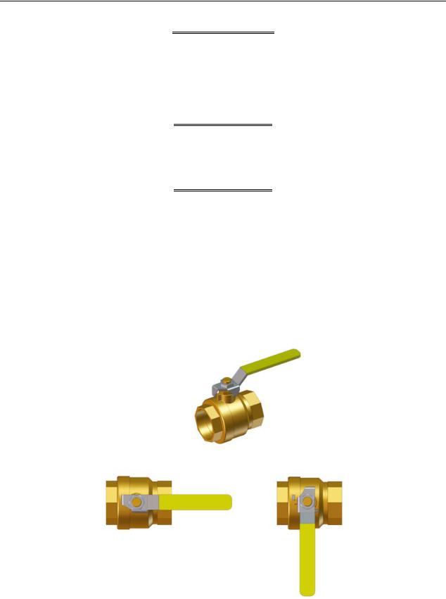
1.2 EMERGENCY SHUTDOWN
If overheating occurs or the gas supply fails to shut off, close the manual gas shutoff valve (Figure 1-1) located external to the unit.
NOTE
The Installer must identify and indicate the location of the emergency shutdown manual gas valve to operating personnel.
MANUAL GAS SHUT-OFF VALVE
VALVE OPEN |
VALVE CLOSED |
Figure 1-1: Manual Gas Shutoff Valve
Page 12 of 210 |
AERCO International, Inc. •100 Oritani Dr. • Blauvelt, NY 10913 |
OMM-0086_0D |
03/20/14 |
Ph.: 800-526-0288 |
GF-133 |

Benchmark 6000 Boiler Installation, Operation & Maintenance Manual
CHAPTER 1 – SAFETY PRECAUTIONS
1.3 PROLONGED SHUTDOWN
After prolonged shutdown, it is recommended that the startup procedures in Chapter 4 and the safety device test procedures in Chapter 6 of this manual be performed to verify all systemoperating parameters. If there is an emergency, turn off the electrical power supply to the AERCO boiler and close the manual gas valve located upstream of the unit. The installer must identify the emergency shut-off device.
1.4 MASSACHUSETTS INSTALLATIONS
Boiler installations within the Commonwealth of Massachusetts must conform to the following requirements:
•Boiler must be installed by a plumber or a gas fitter who is licensed within the Commonwealth of Massachusetts.
•Prior to unit operation, the complete gas train and all connections must be leak tested using a non-corrosive soap.
•AERCO provides an optional external CO Detector, part number 58092. It can be installed and configured to simply sound an alarm or to shut down the boiler(s) if CO concentrations rise above a configurable threshold. Contact your AERCO representative for details.
•The vent termination must be located a minimum of 4 feet above grade level. If side-wall venting is used, the installation must conform to the following requirements extracted from
248 CMR 5.08 (2):
(a)For all side wall horizontally vented gas fueled equipment installed in every dwelling, building or structure used in whole or in part for residential purposes, including those owned or operated by the Commonwealth and where the side wall exhaust vent termination is less than seven (7) feet above finished grade in the area of the venting, including but not limited to decks and porches, the following requirements shall be satisfied:
•INSTALLATION OF CARBON MONOXIDE DETECTORS. At the time of installation of the side wall horizontal vented gas fueled equipment, the installing plumber or gasfitter shall observe that a hard wired carbon monoxide detector with an alarm and battery back-up is installed on the floor level where the gas equipment is to be installed. In addition, the installing plumber or gasfitter shall observe that a battery operated or hard wired carbon monoxide detector with an alarm is installed on each additional level of the dwelling, building or structure served by the side wall horizontal vented gas fueled equipment. It shall be the responsibility of the property owner to secure the services of qualified licensed professionals for the installation of hard wired carbon monoxide detectors.
a.In the event that the side wall horizontally vented gas fueled equipment is installed in a crawl space or an attic, the hard wired carbon monoxide detector with alarm and battery back-up may be installed on the next adjacent floor level.
b.In the event that the requirements of this subdivision can not be met at the time of completion of installation, the owner shall have a period of thirty (30) days to comply with the above requirements; provided, however, that during said thirty (30) day period, a battery operated carbon monoxide detector with an alarm shall be installed.
1.APPROVED CARBON MONOXIDE DETECTORS. Each carbon monoxide detector as required in accordance with the above provisions shall comply with NFPA 720 and be ANSI/UL 2034 listed and IAS certified.
OMM-0086_0D |
AERCO International, Inc. •100 Oritani Dr. • Blauvelt, NY 10913 |
Page 13 of 210 |
GF-133 |
Ph.: 800-526-0288 |
03/20/14 |

Benchmark 6000 Boiler Installation, Operation & Maintenance Manual
CHAPTER 1 – SAFETY PRECAUTIONS
2. SIGNAGE. A metal or plastic identification plate shall be permanently mounted to the exterior of the building at a minimum height of eight (8) feet above grade directly in line with the exhaust vent terminal for the horizontally vented gas fueled heating appliance or equipment. The sign shall read, in print size no less than one-half (1/2) inch in size, "GAS VENT DIRECTLY BELOW.
KEEP CLEAR OF ALL OBSTRUCTIONS".
3. INSPECTION. The state or local gas inspector of the side wall horizontally vented gas fueled equipment shall not approve the installation unless, upon inspection, the inspector observes carbon monoxide detectors and signage installed in accordance with the provisions of 248 CMR 5.08(2)(a)1 through 4.
(b)EXEMPTIONS: The following equipment is exempt from 248 CMR 5.08(2)(a)1 through 4:
1.The equipment listed in Chapter 10 entitled "Equipment Not Required To Be Vented" in the most current edition of NFPA 54 as adopted by the Board; and
2.Product Approved side wall horizontally vented gas fueled equipment installed in a room or structure separate from the dwelling, building or structure used in whole or in part for residential purposes.
(c)MANUFACTURER REQUIREMENTS - GAS EQUIPMENT VENTING SYSTEM PROVIDED. When the manufacturer of Product Approved side wall horizontally vented gas equipment provides a venting system design or venting system components with the equipment, the instructions provided by the manufacturer for installation of the equipment and the venting system shall include:
1.Detailed instructions for the installation of the venting system design or the venting system components; and
2.A complete parts list for the venting system design or venting system.
(d)MANUFACTURER REQUIREMENTS - GAS EQUIPMENT VENTING SYSTEM NOT PROVIDED. When the manufacturer of a Product Approved side wall horizontally vented gas fueled equipment does not provide the parts for venting the flue gases, but identifies "special venting systems", the following requirements shall be satisfied by the manufacturer:
1.The referenced "special venting system" instructions shall be included with the appliance or equipment installation instructions; and
2.The "special venting systems" shall be Product Approved by the Board, and the instructions for that system shall include a parts list and detailed installation instructions.
(e)A copy of all installation instructions for all Product Approved side wall horizontally vented gas fueled equipment, all venting instructions, all parts lists for venting instructions, and/or all venting design instructions shall remain with the appliance or equipment at the completion of the installation.
____________________________________________________________________________
[End of Extracted Information From 248 CMR 5.08 (2)]
Page 14 of 210 |
AERCO International, Inc. •100 Oritani Dr. • Blauvelt, NY 10913 |
OMM-0086_0D |
03/20/14 |
Ph.: 800-526-0288 |
GF-133 |

Benchmark 6000 Boiler Installation, Operation & Maintenance Manual
CHAPTER 2 – INSTALLATION
CHAPTER 2. INSTALLATION
2.1 INTRODUCTION
This Chapter provides the descriptions and procedures necessary to unpack, inspect and install the AERCO Benchmark Model BMK 6000 Boiler.
2.2 RECEIVING THE UNIT
Each Benchmark Boiler System is shipped as a single crated unit. The shipping weight for the BMK 6000 Model is approximately 3500 pounds. The unit must be moved with the proper rigging equipment for safety and to avoid equipment damage. The unit should be completely inspected for evidence of shipping damage and shipment completeness at the time of receipt from the carrier and before the bill of lading is signed.
NOTE
AERCO is not responsible for lost or damaged freight. Each unit has a Tip- N-Tell indicator on the outside of the shipping container. This indicates if the unit has been turned on its side during shipment. If the Tip-N-Tell indicator is tripped, do not sign for the shipment. Note the information on the carrier’s paperwork and request a freight claim and inspection by a claims adjuster before proceeding. Any other visual damage to the packaging materials should also be made clear to the delivering carrier.
2.3 MOVING & UNPACKING THE UNIT
While packaged in the shipping container, the unit can be moved using a forklift.
Carefully unpack the unit taking care not to damage the unit enclosure when cutting away packaging materials
After unpacking, closely inspect the unit to make sure there is no evidence of damage not indicated by the Tip-N-Tell indicator. Notify the freight carrier immediately if any damage is detected.
The following accessories come standard with each unit and are either factory installed on the unit or packed separately with the unit:
•Pressure/Temperature Gauge
•ASME Pressure Relief Valve
•Condensate Drain Trap (part no. 24060)
•2” Gas Supply Shutoff Valve
When optional accessories are ordered, they may be packed with the unit, factory installed on the unit, or packed and shipped in a separate container. Any standard or optional accessories shipped loose should be identified and stored in a safe place until ready for installation or use.
OMM-0086_0D |
AERCO International, Inc. •100 Oritani Dr. • Blauvelt, NY 10913 |
Page 15 of 210 |
GF-133 |
Ph.: 800-526-0288 |
03/20/14 |
Benchmark 6000 Boiler Installation, Operation & Maintenance Manual
CHAPTER 2 – INSTALLATION
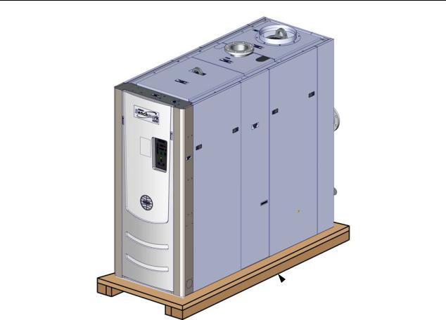
 SHIPPING SKID
Figure 2-1: Benchmark 6000 Mounted on Shipping Skid
2.4 SITE PREPARATION
Ensure that the site selected for installation of the Benchmark Boiler includes:
•Access to AC Input Power at 208 VAC, Three-Phase, 60 Hz @ 30 Amps OR 460 VAC, Three-Phase, 60 Hz @ 20 Amps
•Access to Natural Gas line at a minimum pressure of 14 inches W.C. with the unit in operation (approximately 20” W.C. static).
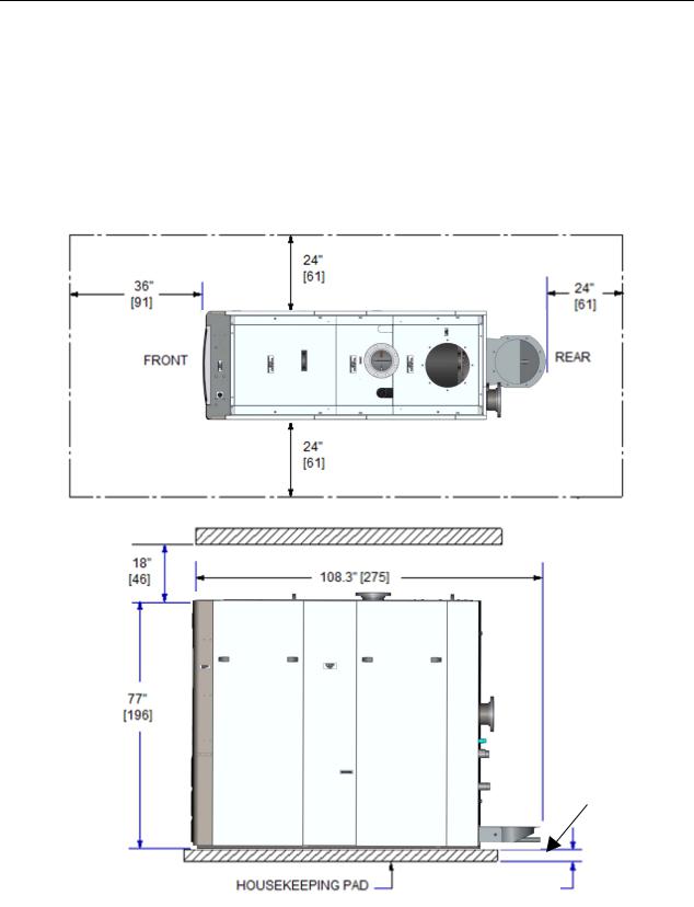
2.4.1 Installation Clearances
The Benchmark Model 6000 Boiler dimensions and minimum acceptable clearances are shown in Figure 2-2. The minimum clearance dimensions, required by AERCO, are listed below. However, if Local Building Codes require additional clearances, these codes shall supersede AERCO’s requirements. Minimum acceptable clearances required are as follows:
•Front : 36 inches (914 mm)
•Sides: 24 inches (610 mm)
•Rear: 24 inches (610 mm)
•Top: 18 inches (457 mm)
All gas piping, water piping and electrical conduit or cable must be arranged so that they do not interfere with the removal of any panels, or inhibit service or maintenance of the unit.
Page 16 of 210 |
AERCO International, Inc. •100 Oritani Dr. • Blauvelt, NY 10913 |
OMM-0086_0D |
03/20/14 |
Ph.: 800-526-0288 |
GF-133 |
Benchmark 6000 Boiler Installation, Operation & Maintenance Manual
CHAPTER 2 – INSTALLATION
IMPORTANT
Ensure that adequate clearance exists at the rear of the unit to permit installation and service maintenance of the AERCO Condensate Trap. Refer to section 2.7 for Condensate Trap installation details.
When using the AERCO Condensate Neutralizer Tank for condensate drainage, the tank must be installed in a pit, OR the boiler and AERCO Condensate Trap must be elevated higher than 4” above the floor. See Condensate Neutralizer Tank Instructions TID-0074 for details.
Housekeeping pad should not extend under the condensate assembly
4” – 8”
4” MINIMUM
Figure 2-2: Benchmark Boiler Model 6000 Clearances
OMM-0086_0D |
AERCO International, Inc. •100 Oritani Dr. • Blauvelt, NY 10913 |
Page 17 of 210 |
GF-133 |
Ph.: 800-526-0288 |
03/20/14 |

Benchmark 6000 Boiler Installation, Operation & Maintenance Manual
CHAPTER 2 – INSTALLATION
 WARNING
KEEP THE UNIT AREA CLEAR AND FREE FROM ALL COMBUSTIBLE MATERIALS AND FLAMMABLE VAPORS OR LIQUIDS.
FOR MASSACHUSSETTS ONLY
For Massachusetts installations, the unit must be installed by a plumber or gas-fitter who is licensed within the Commonwealth of Massachusetts. In addition, the installation must comply with all requirements specified in Chapter 1 (Safety Precautions), pages 14 and 15.
2.4.2 Setting the Unit
The unit must be installed on a concrete housekeeping pad, a minimum of 4 inches and a maximum of 8 inches thick, to ensure proper condensate drainage (see NOTE below).
NOTE
When using the AERCO Condensate Neutralizer Tank for proper condensate drainage, the Neutralizer Tank must be stored in a pit, OR the boiler and AERCO Condensate Trap must be elevated higher than 4” above the floor. Ensure that the condensate assembly is not positioned above the housekeeping pad during installation so as not to interference with condensate piping. See Condensate Tank Instructions TID-0074 for details.
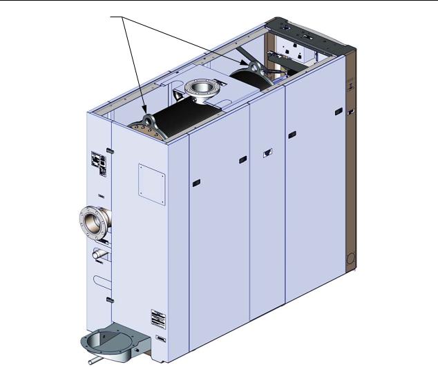
Two (2) lifting lugs are provided at the top of the primary heat exchanger as shown in Figure 2-3. Cut the cardboard at marked locations to provide access to the lifting tabs.
Remove the four (4) lag screws securing the unit to the shipping skid, and, if still in place, remove the front Top Panel. Lift the unit off the shipping skid and position it on the concrete Housekeeping Pad (required) in the desired location.
 WARNING
WHEN LIFTING OR MOVING THE BOILER: DO NOT ATTEMPT
TO MANIPULATE THE BOILER USING THE GAS TRAIN OR
BLOWER. A SPREADER BAR IS REQUIRED FOR ALL
VERTICAL LIFTS.
Page 18 of 210 |
AERCO International, Inc. •100 Oritani Dr. • Blauvelt, NY 10913 |
OMM-0086_0D |
03/20/14 |
Ph.: 800-526-0288 |
GF-133 |
Benchmark 6000 Boiler Installation, Operation & Maintenance Manual
CHAPTER 2 – INSTALLATION
LIFTING TABS
NOTE:
Remove the two top panels to access the lifting tabs.
Figure 2-3: Boiler Lifting Provisions
If anchoring the unit, refer to the dimensional drawings in Appendix F for anchor locations.
In multiple unit installations, it is important to plan the position of each unit in advance. Sufficient space for piping connections and future service/maintenance requirements must also be taken into consideration. All piping must include ample provisions for expansion.
If installing a Combination Control Panel (CCP) system, it is important to identify the Combination Mode Boilers in advance and place them in the proper physical location. Refer to Chapter 5 for information on Combination Mode Boilers.
2.5 SUPPLY AND RETURN PIPING
The Benchmark Boiler utilizes 6” flanged fittings for the water system supply and return piping connections. The physical location of the supply and return piping connections are shown in Figure 2-4. Refer to Appendix F, Drawing AP-A-901 for additional dimensional data.
OMM-0086_0D |
AERCO International, Inc. •100 Oritani Dr. • Blauvelt, NY 10913 |
Page 19 of 210 |
GF-133 |
Ph.: 800-526-0288 |
03/20/14 |
Benchmark 6000 Boiler Installation, Operation & Maintenance Manual
CHAPTER 2 – INSTALLATION
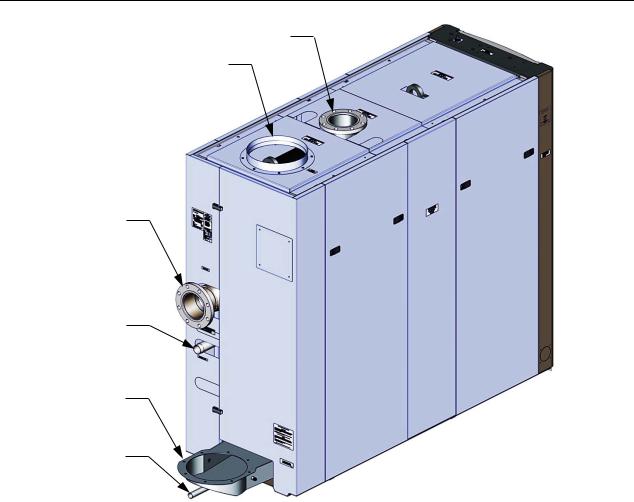
6” WATER OUTLET
AIR INLET
6” WATER INLET
2” GAS INLET
EXHAUST
MANIFOLD
CONDENSATE
DRAIN
Figure 2-4: Supply and Return Locations
2.6 PRESSURE RELIEF VALVE & PRESSURE/TEMPERATURE INDICATOR INSTALLATION
2.6.1 Pressure Relief Valve Installation
Depending on the pressure required, the Benchmark 6000 is supplied with either a single 2” or two (2) 1¼“ ASME rated Pressure Relief Valves. The pressure rating for the relief valve must be specified on the sales order. Available pressure ratings range from 30 psi to 160 psi, depending on pressure vessel maximum rated pressure. Each pressure relief valve is furnished as a kit (92102-Tab) which consists of the relief valve for the pressure rating specified on the Sales Order. The appropriate size reducing bushing and nipple are also included in the kit. The pressure relief valves, nipples and bushings are connected to 45º street elbows already installed on the heat exchanger of the boiler. The relief valves are installed on the top of the boiler as shown in Figure 2-5A. A suitable pipe joint compound should be used on all threaded connections. Any excess should be wiped off to avoid getting any joint compound into the valve body. Each relief valve must be piped to within 12 inches of the floor to prevent injury in the event of a discharge. The discharge piping must be full size, without reduction. No valves, or size reductions are allowed in the discharge line. In multiple unit installations the discharge lines must not be manifolded together. Each must be individually run to a suitable discharge location.
Page 20 of 210 |
AERCO International, Inc. •100 Oritani Dr. • Blauvelt, NY 10913 |
OMM-0086_0D |
03/20/14 |
Ph.: 800-526-0288 |
GF-133 |
Benchmark 6000 Boiler Installation, Operation & Maintenance Manual
CHAPTER 2 – INSTALLATION
Figure 2-5: Pressure Relief Valve Installation Locations
2.6.2 Pressure/Temperature Gauge Installation
A manual Pressure/Temperature Gauge is included in the loose parts kit for installation for installation in the boiler outlet piping. It must be installed so that the sensing bulb is inserted into the hot water outlet flow from the boiler. Refer to Figure 2-5B for sample installations.
Figure 2-5B: Pressure/Temperature Gauge Installation Location
OMM-0086_0D |
AERCO International, Inc. •100 Oritani Dr. • Blauvelt, NY 10913 |
Page 21 of 210 |
GF-133 |
Ph.: 800-526-0288 |
03/20/14 |
Benchmark 6000 Boiler Installation, Operation & Maintenance Manual
CHAPTER 2 – INSTALLATION
2.7 CONDENSATE DRAIN & PIPING
The Benchmark Boiler is designed to condense water vapor from the flue products. Therefore, the installation must have provisions for suitable condensate drainage or collection.
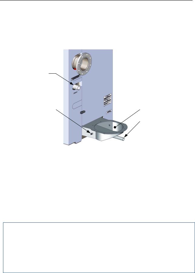
The condensate drain port is located on the exhaust manifold (Figure 2-6) at the rear of the unit. This drain port must be connected to the condensate trap (part no. 24060), which is packed separately within the unit’s shipping container. The condensate trap outlet connection features a tapped 3/4” NPT drain port.
2” GAS INLET
ANALYZER PORTS |
|
|
|
EXHAUST MANIFOLD |
|
|
|||
(2 EA., ONE ON |
|
|
|
|
EACH SIDE) |
|
|
|
CONDENSATE DRAIN |
|
|
|
|
|
|
|
|
|
OUTLET |
Figure 2-6: Condensate Drain Connection Location
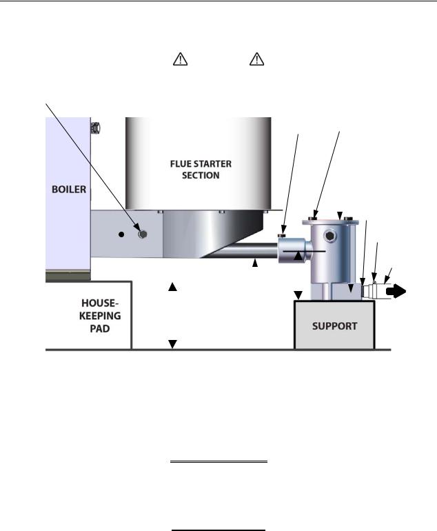
A sample condensate trap installation is shown in Figure 2-7. However, the actual installation details for the trap will vary depending on the available clearances, housekeeping pad height/ dimensions and other prevailing conditions at the site. The following general guidelines must be observed to ensure proper condensate drainage:
•The condensate trap inlet (Figure 2-7) must be level with, or lower than the exhaust manifold drain port.
•The base of the condensate trap must be supported to ensure that it is level (horizontal).
•The trap must be removable for routine maintenance. AERCO recommends that a union be utilized between the exhaust manifold condensate drain port and the trap inlet port.
While observing the above guidelines, install the condensate trap as follows:
Condensate Trap Installation
1.Connect the condensate trap inlet to the exhaust manifold drain connection by sliding the trap inlet onto the drain port. Tighten the thumbscrew on the trap inlet.
2.At the condensate trap outlet, install a stainless steel or PVC 3/4” NPT nipple.
3.Connect a length of 1” I.D. polypropylene hose to the trap outlet and secure with a hose clamp.
4.Route the hose on the trap outlet to a nearby floor drain.
Page 22 of 210 |
AERCO International, Inc. •100 Oritani Dr. • Blauvelt, NY 10913 |
OMM-0086_0D |
03/20/14 |
Ph.: 800-526-0288 |
GF-133 |
Benchmark 6000 Boiler Installation, Operation & Maintenance Manual
CHAPTER 2 – INSTALLATION
If a floor drain is not available, a condensate pump can be used to remove the condensate to drain. The maximum condensate flow rate is 40 GPH. The condensate drain trap, associated fittings and drain line must be removable for routine maintenance.
|
|
|
|
|
|
|
|
CAUTION |
|
|
|
|
|
|
||
|
|
|
|
|
|
|
|
|
|
|
|
|
|
|
||
|
|
|
Use PVC, stainless steel, aluminum or polypropylene for condensate drain |
|||||||||||||
COMBUTION |
|
piping (Figure 2-6). DO NOT use carbon or copper components. |
|
|||||||||||||
|
|
|
|
|
|
|
|
|
|
TRAP INLET INTEGRAL |
||||||
|
|
|
|
|
|
|
|
|
|
|||||||
ANALYZER |
|
|
|
|
|
|
|
|
|
ADAPTOR AND THUMB- |
||||||
PROBE PORT |
|
|
|
|
|
|
|
|
|
SCREW |
TOP COVER |
|||||
|
|
|
|
|
|
|
|
|
|
|
|
|
|
|
|
|
|
|
|
|
|
|
|
|
|
|
|
|
|
|
|
|
THUMB SREWS |
|
|
|
|
|
|
|
|
|
|
|
|
|
|
|
|
(4 each) |
|
|
|
|
|
|
|
|
|
|
|
|
|
|
|
|
CONDENSATE |
|
|
|
|
|
|
|
|
|
|
|
|
|
|
|
|
|
|
|
|
|
|
|
|
|
|
|
|
|
|
|
|
|
TRAP (P/N 24060) |
|
|
|
|
|
|
|
|
|
|
|
|
|
|
|
|
3/4” NPT |
|
|
|
|
|
|
|
|
|
|
|
|
|
|
|
|
NIPPLES |
|
|
|
|
|
|
|
|
|
|
|
|
|
|
|
|
|
EXHAUST |
|
|
|
|
|
|
|
|
|
|
|
|
|
|
|
HOSE |
|
|
|
|
|
|
|
|
|
|
|
|
|
|
|
||
|
|
|
|
|
|
|
|
|
|
|
|
|
|
|
CLAMP |
|
|
|
|
|
|
|
|
|
|
|
|
|
|
|
|
||
MANIFOLD |
|
|
|
|
|
|
|
|
|
|
|
|
|
1” DIAM. |
||
|
|
|
|
|
|
|
|
|
|
|
|
|
|
|
|
|
|
|
|
|
|
|
|
|
|
|
|
|
|
|
|
|
HOSE |
|
|
|
|
|
|
|
|
|
|
|
|
|
|
|
|
|
NOTE |
|
|
|
|
|
|
|
|
|
4” |
|
|
|
|||
|
|
|
|
|
|
|
|
|
|
|
|
|
|
|||
|
|
|
|
|
|
|
|
|
|
|
|
|
|
|||
HOUSKEEPING |
|
|
|
|
|
|
|
|
|
|
|
|
|
|||
|
|
|
|
|
|
EXHAUST |
|
|
|
|
|
|||||
|
|
|
|
|
|
|
|
|
|
|
||||||
PAD MUST NOT |
|
|
|
4” MINIMUM |
MANIFOLD |
|
|
|
|
T O |
||||||
EXTEND |
|
|
|
8” MAXIMUM |
DRAIN PORT |
|
|
|
|
|||||||
UNDER THE |
|
|
|
|
|
|
Tilt down 2° for |
|
|
|
|
FLOOR |
||||
|
|
|
|
|
|
|
|
|
|
|||||||
CONDENSATE |
|
|
|
|
|
|
gravity flow |
|
|
|
|
DRAIN |
||||
|
|
|
|
|
|
|
|
|
|
|||||||
ASSEMBLY. |
|
|
|
|
|
|
|
|
|
|
|
|
|
|
||
Figure 2-7: Sample Condensate Trap Installation
2.8 GAS SUPPLY PIPING
The AERCO Benchmark Gas Components and Supply Design Guide, GF-2030 must be consulted prior to designing or installing any gas supply piping.
 WARNING
NEVER USE MATCHES, CANDLES, FLAMES OR OTHER
SOURCES OF IGNITION TO CHECK FOR GAS LEAKS.
 CAUTION
Many soaps used for gas pipe leak testing are corrosive to metals. Therefore, piping must be rinsed thoroughly with clean water after leak checks have been completed.
OMM-0086_0D |
AERCO International, Inc. •100 Oritani Dr. • Blauvelt, NY 10913 |
Page 23 of 210 |
GF-133 |
Ph.: 800-526-0288 |
03/20/14 |

Benchmark 6000 Boiler Installation, Operation & Maintenance Manual
CHAPTER 2 – INSTALLATION
NOTE
All gas piping must be arranged so that it does not interfere with removal of any covers, inhibit service/maintenance, or restrict access between the unit and walls, or another unit.
Benchmark 6000 MBH units contain a 2 inch NPT gas inlet connection on the back of the unit as shown in Figure 2-4.
Prior to installation, all pipes should be de-burred and internally cleared of any scale, metal chips or other foreign particles. Do not install any flexible connectors or unapproved gas fittings. Piping must be supported from the floor, ceiling or walls only and must not be supported by the unit.
A suitable piping compound, approved for use with natural gas, should be used. Any excess must be wiped off to prevent clogging of components.
To avoid unit damage when pressure testing gas piping, isolate the unit from the gas supply piping. At no time should the gas pressure applied to the unit exceed 56” W.C. (2 psig). Leak test all external piping thoroughly using a soap and water solution or suitable equivalent. The gas piping used must meet all applicable codes.
2.8.1 Gas Supply Specifications
The gas supply input specifications to the unit for Natural Gas are as follows:
•The maximum static pressure to the unit must not exceed 56 inches W.C. (2 psi).
•The gas supply piping and pressure to the unit must be sufficient to provide 6000 cfh while maintaining a gas pressure of 14 inches W.C. for FM gas trains while in operation.
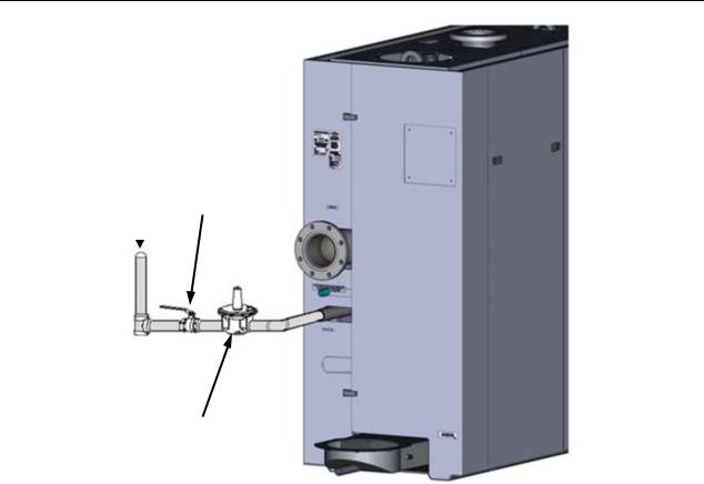
2.8.2 Manual Gas Shutoff Valve
A manual shut-off valve must be installed in the gas supply line upstream of the boiler as shown in Figure 2-8. Maximum allowable gas pressure to the boiler is 56” W.C. (2 psi).
2.8.3 External Gas Supply Regulator
An external gas pressure regulator is required on the gas inlet piping under most conditions (see sections 2.8.3.1 and 2.8.3.2, below). Regulators must conform to the following specifications:
•The external natural gas regulator must be capable of regulating 300,000 – 6,000,000 BTU/HR of natural gas while maintaining a gas pressure of 14” W.C. minimum to the unit.
•A lock-up style regulator MUST be used when gas supply pressure will exceed 2 PSI.
2.8.3.1 Massachusetts Installations Only
For Massachusetts installations, a mandatory external gas supply regulator must be positioned as shown in Figure 2-8. The gas supply regulator must be properly vented to outdoors. Consult the local gas utility for detailed requirements concerning venting of the supply gas regulator.
2.8.3.2 All Installations (Except Massachusetts)
For multi-unit installations (other than Massachusetts) that EXCEED 1 PSI gas pressure, a separate external gas supply regulator, as shown in Figure 2-8, is highly recommended. No regulator is required for gas pressures below 1 PSI of pressure, but above 2 PSI it is mandatory. Consult the local gas utility for detailed requirements concerning venting of the supply gas regulator.
Page 24 of 210 |
AERCO International, Inc. •100 Oritani Dr. • Blauvelt, NY 10913 |
OMM-0086_0D |
03/20/14 |
Ph.: 800-526-0288 |
GF-133 |
Benchmark 6000 Boiler Installation, Operation & Maintenance Manual
CHAPTER 2 – INSTALLATION
NATURAL |
|
2” MANUAL |
|
GAS |
|||
GAS SHUT- |
|||
SUPPLY |
|||
OFF VALVE |
|||
|
|
||
|
|
|
|
GAS PRESSURE
REGULATOR
Figure 2-8: Manual Gas Shut-Off Valve Location
2.9 AC ELECTRICAL POWER WIRING
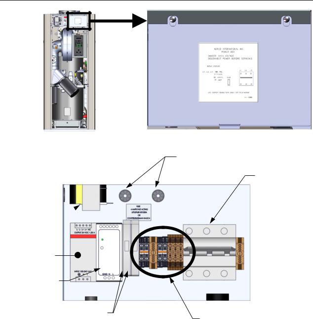
The AERCO Benchmark Electrical Power Wiring Guide, GF-2060, must be consulted prior to connecting any AC power wiring to the unit. External AC power connections are made to the unit inside the Power Box on the front of the unit. Remove the unit’s front panel to access the Power Box, which is mounted in the upper right corner of the unit as shown in Figure 2-9. Loosen the four Power Box cover screws and remove the cover to access the AC terminal block connections, and other internal components shown in Figure 2-10.
OMM-0086_0D |
AERCO International, Inc. •100 Oritani Dr. • Blauvelt, NY 10913 |
Page 25 of 210 |
GF-133 |
Ph.: 800-526-0288 |
03/20/14 |
Benchmark 6000 Boiler Installation, Operation & Maintenance Manual
CHAPTER 2 – INSTALLATION
Power Box, located in the unit’s upperright corner.
Figure 2-9: Power Box With Closed Cover
WIRE CONDUITS
POWER
BREAKER
TRANSFORMER 
24V POWER SUPPLY
12V POWER SUPPLY
FUSE BLOCKS (2)
TERMINAL BLOCKS
Figure 2-10: Power Box Internal Components
With the exception of the transformer shown in Figure 2-10, all of the components in the Power Box are mounted on a DIN rail.
NOTE
All electrical conduit and hardware must be installed so that it does not interfere with the removal of any unit covers, inhibit service/maintenance, or prevent access between the unit and walls or another unit.
Page 26 of 210 |
AERCO International, Inc. •100 Oritani Dr. • Blauvelt, NY 10913 |
OMM-0086_0D |
03/20/14 |
Ph.: 800-526-0288 |
GF-133 |
Benchmark 6000 Boiler Installation, Operation & Maintenance Manual
CHAPTER 2 – INSTALLATION
2.9.1 Electrical Power Requirements
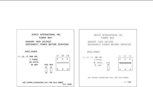
The Benchmark Boiler is available in two voltage configurations: either 208 VAC, three-phase, 60 Hz @ 30A or 460 VAC, three-phase, 60 Hz @ 15A. The Power Box contains terminal blocks as shown in Figure 2-10. In addition, a label showing the required AC power connections is provided on the front cover of the Power Box, as shown in Figure 2-11.
Figure 2-11: Power Box Cover Labels – 208VAC (Left) and 460VAC (Right)
Each unit must be connected to a dedicated electrical circuit. NO OTHER DEVICES SHOULD BE ON THE SAME ELECTRICAL CIRCUIT AS THE BOILER.
A double-pole switch must be installed on the electrical supply line in an easily accessible location to quickly and safely disconnect electrical service. DO NOT attach the switch to sheet metal enclosures of the unit.
After placing the unit in service, the ignition safety shutoff device must be tested. If an external electrical power source is used, the installed boiler must be electrically bonded to ground in accordance with the requirements of the authority having jurisdiction. In the absence of such requirements, the installation shall conform to National Electrical Code (NEC), ANSI/NFPA 70 and/or the Canadian Electrical Code (CEC) Part I, CSA C22.1 Electrical Code.
For electrical power wiring diagrams, see the AERCO Benchmark Electrical Power Guide, (GF2060).
2.10 FIELD CONTROL WIRING
Each unit is fully wired from the factory with an internal operating control system. No field control wiring is required for normal operation. However, the C-More Control system used with all Benchmark units does allow for some additional control and monitoring features. Wiring connections for these features are made on the Input/Output (I/O) board located behind the removable front panel assembly of the unit. The I/O board is located in the I/O Box. The I/O board terminal strip connections are shown in Figure 2-13. All field wiring is installed from the rear of the panel by routing the wires through one of the four bushings provided on the sides of the I/O board.
Refer to the wiring diagram provided below the I/O Box (Figure 2-13) when making all wiring connections.
OMM-0086_0D |
AERCO International, Inc. •100 Oritani Dr. • Blauvelt, NY 10913 |
Page 27 of 210 |
GF-133 |
Ph.: 800-526-0288 |
03/20/14 |

Benchmark 6000 Boiler Installation, Operation & Maintenance Manual
CHAPTER 2 – INSTALLATION
I/O Box, located in the unit’s upper-left corner.
Figure 2-12a: Input/Output (I/O) Box Location
TERMINAL STRIPS
I/O PCB
BOARD
Figure 2-12b: Input/Output (I/O) Box Interior
NOTE
Use Figure 2-13 to determine the functions of the I/O PCB connections. Do not use the silkscreened labels on the PCB itself, as these may not match the function names. There is a diagram of the connection functions on the cover of the I/O Box as well.
Page 28 of 210 |
AERCO International, Inc. •100 Oritani Dr. • Blauvelt, NY 10913 |
OMM-0086_0D |
03/20/14 |
Ph.: 800-526-0288 |
GF-133 |
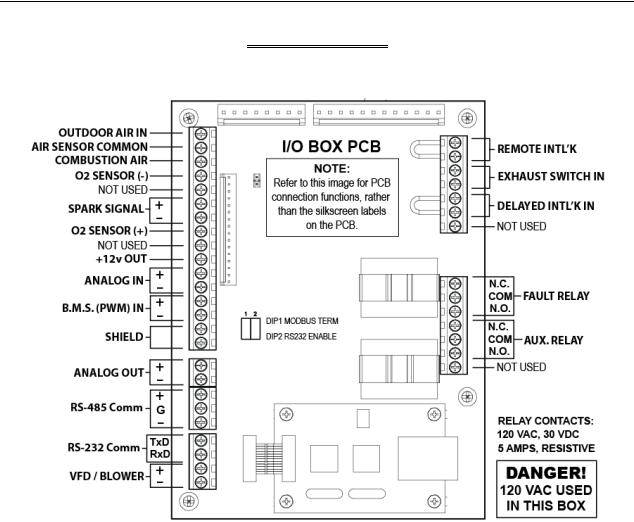
Benchmark 6000 Boiler Installation, Operation & Maintenance Manual
CHAPTER 2 – INSTALLATION
 CAUTION
DO NOT make any connections to the I/O Box terminals labeled “NOT USED”. Attempting to do so may cause equipment damage.
Figure 2-13: I/O Box Terminal Strips
2.10.1 OUTDOOR AIR IN Terminal
An OUTDOOR AIR IN terminal is used for connecting an outdoor temperature sensor (AERCO P/N GM-123525) as required primarily for the Indoor/Outdoor reset mode of operation. It can also be used with another mode if it is desired to use the outdoor sensor enable/disable feature. This feature allows the boiler to be enabled or disabled based on the outdoor air temperature.
The factory default for the outdoor sensor is DISABLED. To enable the sensor and/or select an enable/disable outdoor temperature, see the Configuration menu in Chapter 3.
The outdoor sensor may be wired up to 200 feet from the boiler. It is connected to the OUTDOOR AIR IN and AIR SENSOR COMMON terminals of the I/O Box (see Figure 2-13). Wire the sensor using a twisted shielded pair wire between 18 and 22 AWG. There is no polarity to observe when terminating these wires. The shield is to be connected only to the terminals labeled SHIELD in the I/O Box. The sensor end of the shield must be left free and ungrounded.
When mounting the sensor, it must be located on the North side of the building where an average outside air temperature is expected. The sensor must be shielded from direct sunlight as well as impingement by the elements. If a shield cover is used, it must allow for free air circulation.
OMM-0086_0D |
AERCO International, Inc. •100 Oritani Dr. • Blauvelt, NY 10913 |
Page 29 of 210 |
GF-133 |
Ph.: 800-526-0288 |
03/20/14 |

Benchmark 6000 Boiler Installation, Operation & Maintenance Manual
CHAPTER 2 – INSTALLATION
2.10.2 COMBUSTION AIR Terminal
The COMBUSTION AIR terminal is used to monitor the combustion air temperature sensor. This input is always enabled and is a “to view only” input that can be seen in the operating menu. The sensor is an AERCO BALCO wire sensor Part No. 12449. A resistance chart for this sensor is provided in APPENDIX C. This sensor is an active part of the combustion control system and must be operational for accurate air/fuel mixing control.
2.10.3 O2 SENSOR Terminals
The O2 SENSOR (–) and O2 SENSOR (+) terminals are used to connect an external oxygen sensor to the I/O box. The O2 concentration is displayed in the operating menu of the C-More Control system after a 60 second warm-up period.
2.10.4 SPARK SIGNAL Terminals
The SPARK SIGNAL terminals are not in use on the Benchmark 6000.
2.10.5 ANALOG IN Terminals
The ANALOG IN terminals (+ and –) are used when an external signal is used to change the setpoint (Remote Setpoint Mode) of the boiler.
Either a 4 to 20 mA /1 to 5 VDC or a 0 to 20 mA/ 0 to 5 VDC signal may be used to vary the setpoint or air/fuel valve position. The factory default setting is for 4 to 20 mA / 1 to 5 VDC, however this may be changed to 0 to 20 mA / 0 to 5 VDC using the Configuration Menu described in Chapter 3.
If voltage rather than current is selected as the drive signal, a DIP switch must be set on the PMC Board located inside the Control Box. Refer to Appendix D of the C-More Control Panel OMM, GF-112, for information on setting DIP switches.
All supplied signals must be floating (ungrounded) signals. Connections between the source and the boiler’s I/O Box must be made using twisted shielded pair of 18–22 AWG wire such as Belden 9841. Polarity must be maintained and the shield must be connected only at the source end and must be left floating (not connected) at the Boiler’s I/O Box.
Whether using voltage or current for the drive signal, they are linearly mapped to a 40°F to 240°F setpoint or a 0% to 100% air/fuel valve position. No scaling for these signals is provided
2.10.6 B.M.S. (PWM) IN Terminals
The two B.M.S. (PWM) IN terminals are only used to connect the legacy AERCO Boiler Management Systems (BMS), which utilize a 12 millisecond, ON/OFF duty cycle and is Pulse Width Modulated (PWM) to control valve position. A 0% valve position = a 5% ON pulse and a 100% valve position = a 95% ON pulse. Note that these connections cannot be used with the ARECO Control System (ACS).
2.10.7 SHIELD Terminals
The two SHIELD terminals are used to terminate any shields used on sensor wires connected to the unit. Shields must only be connected to these terminals.
2.10.8 ANALOG OUT Terminals
The ANALOG OUT terminals (+ & -) output from 0 to 20 mA and may be used to monitor Setpoint, Outlet Temperature, Valve Position 4-20 mA, Valve Position 0-10v or be set to OFF. Default setting in the C-More controller is Valve Position 0-10v and settings behave as follows:
Page 30 of 210 |
AERCO International, Inc. •100 Oritani Dr. • Blauvelt, NY 10913 |
OMM-0086_0D |
03/20/14 |
Ph.: 800-526-0288 |
GF-133 |
Loading...