


Instruction |
GF-120 |
No. |
|
|
|
AERCO INTERNATIONAL, Inc., Northvale, New Jersey, 07647 |
USA |
Installation, Operation
& Maintenance Instructions
Benchmark 1.5LN
Series
Gas Fired
Low NOx
Boiler System
Condensing, Modulating
Forced Draft, Hot Water Boiler
1,500,000 BTU/H Input
Printed in U.S.A. |
REVISED MAY, 2009 |

Telephone Support
Direct to AERCO Technical Support
(8 to 5 pm EST, Monday through Friday):
1-800-526-0288
AERCO International, Inc.
159 Paris Avenue
Northvale, NJ 07647-0128
www.aerco,com
© AERCO International, Inc., 2009
The information contained in this installation, operation and maintenance manual is subject to change without notice from AERCO International, Inc.
AERCO makes no warranty of any kind with respect to this material, including but not limited to implied warranties of merchantability and fitness for a particular application. AERCO International is not liable for errors appearing in this manual. Nor for incidental or consequential damages occurring in connection with the furnishing, performance, or use of this material.

CONTENTS
GF-120 - AERCO BENCHMARK 1.5LN GAS FIRED LOW NOx BOILER
Operating & Maintenance Instructions
FOREWARD |
|
|
|
A |
|
Chapter 1 – SAFETY PRECAUTIONS |
|
|
1-1 |
||
Para. |
Subject |
Page |
Para. |
Subject |
Page |
1-1 |
Warnings & Cautions |
1-1 |
1-3 |
Prolonged Shutdown |
1-2 |
1-2 |
Emergency Shutdown |
1-2 |
|
|
|
Chapter 2 – INSTALLATION |
|
|
|
2-1 |
|
Para. |
Subject |
Page |
Para. |
Subject |
Page |
2.1 |
Introduction |
2-1 |
2.9 |
Modes of Operation and Field |
2-5 |
2.2 |
Receiving the Unit |
2-1 |
|
Control Wiring |
|
2.3 |
Unpacking |
2-1 |
2.10 |
I/O Box Connections |
2-7 |
2.4 |
Site Preparation |
2-1 |
2.11 |
Auxiliary Relay Contacts |
2-9 |
2.5 |
Supply and Return Piping |
2-3 |
2.12 |
Flue Gas Vent Installation |
2-9 |
2.6 |
Condensate Drains |
2-3 |
2.13 |
Combustion Air |
2-9 |
2.7 |
Gas Supply Piping |
2-4 |
|
|
|
2.8 |
AC Electrical Power Wiring |
2-5 |
|
|
|
Chapter 3 – CONTROL PANEL COMPONENTS AND |
|
||||
|
OPERATING PROCEDURES |
|
|
3-1 |
|
Para. |
Subject |
Page |
Para. |
Subject |
Page |
3.1 |
Introduction |
3-1 |
3.6 |
Configuration Menu |
3-6 |
3.2 |
Control Panel Description |
3-1 |
3.7 |
Tuning Menu |
3-7 |
3.3 |
Control Panel Menus |
3-4 |
3.8 |
Start Sequence |
3-7 |
3.4 |
Operating Menu |
3-5 |
3.9 |
Start/Stop Levels |
3-9 |
3.5 |
Setup Menu |
3-5 |
|
|
|
Chapter 4 – INITIAL START-UP |
|
|
|
4-1 |
|
Para. |
Subject |
Page |
Para. |
Subject |
Page |
4.1 |
Initial Startup Requirements |
4-1 |
4.4 |
Unit Reassembly |
4-5 |
4.2 |
Tools and Instruments for |
4-1 |
4.5 |
Over-Temperature Limit |
4-5 |
|
Combustion Calibration |
|
|
Switches |
|
4.3 |
Natural Gas Combustion |
4-2 |
|
|
|
|
Calibration |
|
|
|
|
i
CONTENTS
Chapter 5 – MODE OF OPERATION |
|
|
5-1 |
||
Para. |
Subject |
Page |
Para. |
Subject |
Page |
5.1 |
Introduction |
5-1 |
5.6 |
Boiler Management System |
5-4 |
5.2 |
Indoor/Outdoor Reset Mode |
5-1 |
|
(BMS) |
|
5.3 |
Constant Setpoint Mode |
5-2 |
5.7 |
Combination Control System |
5-5 |
5.4 |
Remote Setpoint Mode |
5-2 |
|
(CCS) |
|
5.5 |
Direct Drive Modes |
5-3 |
|
|
|
Chapter 6 – SAFETY DEVICE TESTING PROCEDURES |
6-1 |
||||
Para. |
Subject |
Page |
Para. |
Subject |
Page |
6.1 |
Testing of Safety Devices |
6-1 |
6.8 |
Air Flow Fault Test |
6-4 |
6.2 |
Low Gas Pressure Fault Test |
6-1 |
6.9 |
SSOV Proof of Closure Switch |
6-4 |
6.3 |
High Gas Pressure Test |
6-2 |
6.10 |
Purge Switch Open During |
6-5 |
6.4 |
Low Water Level Fault Test |
6-2 |
|
Purge |
|
6.5 |
Water Temperature Fault Test |
6-2 |
6.11 |
Ignition Switch Open During |
6-5 |
6.6 |
Interlock Tests |
6-3 |
|
Ignition |
|
6.7 |
Flame Fault Test |
6-4 |
6.12 |
Safety Pressure Relief Valve |
6-6 |
|
|
|
|
Test |
|
Chapter 7 – MAINTENANCE REQUIREMENTS |
|
7-1 |
|||
Para. |
Subject |
Page |
Para. |
Subject |
Page |
7.1 |
Maintenance Schedule |
7-1 |
7.7 |
Condensate Drain Trap |
7-4 |
7.2 |
Spark Ignitor |
7-1 |
7.8 |
Shutting the Boiler Down For An |
7-4 |
7.3 |
Flame Detector |
7-2 |
|
Extended Period of Time |
|
7.4 |
Combustion Calibration |
7-2 |
7.9 |
Placing The Boiler Back In |
7-4 |
7.5 |
Safety Device Testing |
7-3 |
|
Service After A Prolonged |
|
7.6 |
Burner Assembly |
7-3 |
|
Shutdown |
|
Chapter 8 – TROUBLESHOOTING GUIDE |
|
|
8-1 |
||
Para. |
Subject |
Page |
Para. |
Subject |
Page |
8.1 |
Introduction |
8-1 |
|
|
|
ii
CONTENTS
APPENDICES
App |
Subject |
Page |
App |
Subject |
Page |
A |
Boiler Menu Item Descriptions |
A-1 |
E |
Boiler Default Settings |
E-1 |
B |
Startup, Status and Fault |
B-1 |
F |
Dimensional and Part Drawings |
F-1 |
|
Messages |
|
G |
Piping Drawings |
G-1 |
C |
Temperature Sensor Resistance |
C-1 |
H |
Wiring Schematics |
H-1 |
|
Chart |
|
I |
Recommended Periodic Testing |
I-1 |
D |
Indoor/Outdoor Reset Ratio |
D-1 |
|
Checklist |
|
|
Charts |
|
J |
Benchmark Control Panel Views |
J-1 |
WARRANTIES |
W-1 |
iii
FOREWORD
Foreword
The AERCO Benchmark 1.5LN Boiler is a modulating unit. It represents a true industry advance that meets the needs of today's energy and environmental concerns. Designed for application in any closed loop hydronic system, the Benchmark's modulating capability relates energy input directly to fluctuating system loads. The Benchmark 1.5, with its 20:1 turn down ratio and condensing capability, provides extremely high efficiencies and makes it ideally suited for modern low temperature, as well as, conventional heating systems.
The Benchmark 1.5 operates at inputs ranging from 75,000 BTU/hr. to 1,500,000 BTU/hr. The output of the boiler is a function of the unit’s firing rate and return water temperature. Output ranges from 74,250 BTU/hr. to 1,450,000 BTU/hr., depending on operating conditions.
When installed and operated in accordance with this Instruction Manual, the Benchmark 1.5 Boiler complies with the NOx emission standards outlined in:
• South Coast Air Quality Management District (SCAQMD), Rule 1146.2
Whether used in singular or modular arrangements, the Benchmark 1.5 offers the maximum flexibility in venting with minimum installation space requirements. The Benchmark's advanced electronics are available in several selectable modes of operation offering the most efficient operating methods and energy management system integration.
For service or parts, contact your local sales representative or AERCO INTERNATIONAL.
NAME:
ORGANIZATION:
ADDRESS:
TELEPHONE:
INSTALLATION DATE: _____________________________________________
A
SAFETY PRECAUTIONS
CHAPTER 1 SAFETY PRECAUTIONS
1.1 WARNINGS & CAUTIONS
Installers and operating personnel MUST, at all times, observe all safety regulations. The following warnings and cautions are general and must be given the same attention as specific precautions included in these instructions. In addition to all the requirements included in this AERCO Instruction Manual, the installation of units MUST conform with local building codes, or, in the absence of local codes, ANSI Z223.1 (National Fuel Gas Code Publication No. NFPA54). Where ASME CSD-1 is required by local jurisdiction, the installation must conform to CSD-1.
Where applicable, the equipment shall be installed in accordance with the current Installation Code for Gas Burning Appliances and Equipment, CGA B149, and applicable Provincial regulations for the class; which should be carefully followed in all cases. Authorities having jurisdiction should be consulted before installations are made.
IMPORTANT
This Instruction Manual is an integral part of the product and must be maintained in legible condition. It must be given to the user by the installer and kept in a safe place for future reference.
WARNINGS!
MUST BE OBSERVED TO PREVENT SERIOUS INJURY.
WARNING!
BEFORE ATTEMPTING TO PERFORM ANY MAINTENANCE ON THE UNIT, SHUT OFF ALL GAS AND ELECTRICAL INPUTS TO THE UNIT.
WARNING!
THE EXHAUST VENT PIPE OF THE UNIT OPERATES UNDER A POSITIVE PRESSURE AND THEREFORE MUST BE COMPLETELY SEALED TO PREVENT LEAKAGE OF COMBUSTION PRODUCTS INTO LIVING SPACES.
WARNING
DO NOT USE MATCHES, CANDLES, FLAMES, OR OTHER SOURCES OF IGNITION TO CHECK FOR GAS LEAKS.
WARNING!
FLUIDS UNDER PRESSURE MAY CAUSE INJURY TO PERSONNEL OR DAMAGE TO EQUIPMENT WHEN RELEASED. BE SURE TO SHUT OFF ALL INCOMING AND OUTGOING WATER SHUTOFF VALVES. CAREFULLY DECREASE ALL TRAPPED PRESSURES TO ZERO BEFORE PERFORMING MAINTENANCE.
WARNING!
ELECTRICAL VOLTAGES UP TO 120 VAC MAY BE USED IN THIS EQUIPMENT. THEREFORE THE COVER ON THE UNIT’S POWER BOX (LOCATED BEHIND THE FRONT PANEL DOOR) MUST BE INSTALLED AT ALL TIMES, EXCEPT DURING MAINTENANCE AND SERVICING.
CAUTIONS!
Must be observed to prevent equipment damage or loss of operating effectiveness.
CAUTION!
Many soaps used for gas pipe leak testing are corrosive to metals. The piping must be rinsed thoroughly with clean water after leak checks have been completed.
CAUTION!
DO NOT use this boiler if any part has been under water. Call a qualified service technician to inspect and replace any part that has been under water.
1-1
SAFETY PRECAUTIONS
1.2 EMERGENCY SHUTDOWN
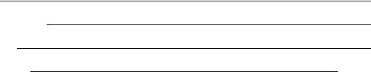
If overheating occurs or the gas supply fails to shut off, close the manual gas shutoff valve (Figure 1-1) located external to the unit.
IMPORTANT
The Installer must identify and indicate the location of the emergency shutdown manual gas valve to operating personnel.
1.3 PROLONGED SHUTDOWN
After prolonged shutdown, it is recommended that the startup procedures in Chapter 4 and the safety device test procedures in Chapter 6 of this manual be performed, to verify all systemoperating parameters. If there is an emergency, turn off the electrical power supply to the AERCO boiler and close the manual gas valve located upstream the unit. The installer is to identify the emergency shut-off device.
Figure 1-1
Manual Gas Shutoff Valve
1-2
INSTALLATION
CHAPTER 2 INSTALLATION
2.1 INTRODUCTION
This Chapter provides the descriptions and procedures necessary to unpack, inspect and install the AERCO Benchmark 1.5 Boiler. Brief descriptions are also provided for each available mode of operation. Detailed procedures for implementing these modes are provided in Chapter 5.
2.2 RECEIVING THE UNIT
Each Benchmark 1.5 System is shipped as a single crated unit. The shipping weight is approximately 1551 pounds. The unit must be moved with the proper rigging equipment for safety and to avoid equipment damage. The unit should be completely inspected for evidence of shipping damage and shipment completeness at the time of receipt from the carrier and before the bill of lading is signed.
NOTE
AERCO is not responsible for lost or damaged freight.
Each unit has a Tip-N-Tell indicator on the outside of the crate. This indicates if the unit has been turned on its side during shipment. If the Tip-N-Tell indicator is tripped, do not sign for the shipment. Note the information on the carrier’s paperwork and request a freight claim and inspection by a claims adjuster before proceeding. Any other visual damage to the packaging materials should also be made clear to the delivering carrier.
•Pressure/Temperature Gauge
•Spare Spark Igniter
•Spare Flame Detector
•ASME Pressure Relief Valve
•Condensate Drain Trap
•1-1/2” Gas Supply Shutoff Valve
When ordered, optional accessories may be packed separately, packed within the boiler shipping container, or may be installed on the boiler. Any standard or optional accessories shipped loose should be identified and stored in a safe place until ready for installation or use.
2.4 SITE PREPARATION.
Ensure that the site selected for installation of the Benchmark 1.5 Boiler includes:
•Access to AC Input Power at 120 VAC, 1- Phase, 60 Hz @ 20
•Access to Natural Gas line at a minimum pressure of 4 inches W.C.
2.4.1 Installation Clearances
The unit must be installed with the prescribed clearances for service as shown in Figure 2-1. The minimum clearance dimensions, required by AERCO, are listed below. However, if Local Building Codes require additional clearances, these codes shall supersede AERCO’s requirements. Minimum acceptable clearances required are:
2.3 UNPACKING
Carefully unpack the unit taking care not to damage the unit enclosure when cutting away packaging materials
A close inspection of the unit should be made to ensure that there is no evidence of damage not indicated by the Tip-N-Tell indicator. The freight carrier should be notified immediately if any damage is detected.
The following accessories come standard with each unit and are either packed separately within the unit’s packing container or are factory installed on the boiler:
•Sides: 24 inches
•Front : 24 inches
• Rear: 30 inches
• Top: 18 inches
All gas piping, water piping and electrical conduit or cable must be arranged so that they do not interfere with the removal of any panels, or inhibit service or maintenance of the unit.
2-1

INSTALLATION
Figure 2-1 Benchmark 1.5 Boiler Clearances
WARNING
KEEP THE UNIT AREA CLEAR AND FREE FROM ALL COMBUSTIBLE MATERIALS AND FLAMMABLE VAPORS OR LIQUIDS.
CAUTION
While packaged in the shipping container, the boiler must be moved by pallet jack or forklift from the FRONT ONLY.
2.4.2 Setting the Unit
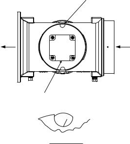
The unit must be installed on a 4 inch to 6 inch housekeeping pad to ensure proper condensate drainage. If anchoring the unit, refer to the dimensional drawings in Appendix F for anchor locations. Two lifting tabs are provided at the top of the heat exchanger as shown in Figure 2-2. USE THE TABS SHOWN IN FIGURE 2-2 TO LIFT AND MOVE THE UNIT. Remove the front top panel from the unit to provide access to the lifting tabs. Remove the four (4) lag screws securing the unit to the shipping skid. Lift the unit off the shipping skid and position it on the 4 inch to 6 inch housekeeping concrete pad (required) in the desired location.
BLOWER
LIFTING |
LIFTING |
|
TAB |
||
TAB |
||
|
AIR/FUEL


VALVE
FRONT
Figure 2-2
Partial Top View Showing Lifting Tab
Locations
In multiple unit installations, it is important to plan the position of each unit in advance. Sufficient space for piping connections and future service/maintenance requirements must also be taken into consideration. All piping must include ample provisions for expansion.
2-2
If installing a Combination Control Panel (CCP) system, it is important to identify the Combination Mode Boilers in advance and place them in the proper physical location. Refer to Chapter 5 for information on Combination Mode Boilers.
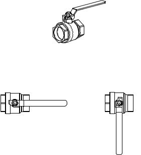
2.5 SUPPLY AND RETURN PIPING
The Benchmark 1.5 Boiler utilizes 3” 150# flanges for the water system supply and return piping connections. The physical location of the supply and return piping connections are on the rear of the unit as shown in Figure 2-3. Refer to Appendix F, Drawing AP-A-832 for additional dimensional data.
Figure 2-3
Supply and Return Locations
2.6 CONDENSATE DRAIN
The Benchmark 1.5 Boiler is designed to condense water vapor from the flue products. Therefore, the installation must have provisions for suitable condensate drainage or collection.
The drain pipe located on the exhaust manifold must be connected to a condensate trap which is packed separately within the unit’s shipping container.
The procedure to install and connect the condensate drain is provided in paragraph 2.6.1.
INSTALLATION
Figure 2-4
Condensate Drain Connection Location
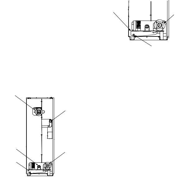
2.6.1 Exhaust Manifold Condensate Drain
The exhaust manifold drain pipe connection shown in Figure 2-4, must be connected to a condensate drain trap external to the unit. Refer to Figure 2-5 and install the trap as follows:
1.Position the supplied condensate trap (part no. 24060) on the floor at the rear of the unit.
2.Install 3/4” NPT nipples in the tapped inlet and outlet of the condensate trap.
3.Attach a length of 1” I.D. hose between the exhaust manifold drain pipe and the inlet side of the condensate trap (Figure 2-5). Secure both ends of the hose with clamps.
4.Connect a second length of 1” I.D. hose to the outlet side of the condensate trap and route it to a nearby floor drain.
If a floor drain is not available, a condensate pump can be used to remove the condensate to drain. The maximum condensate flow rate is 20 GPH. The condensate drain trap, associated fittings and drain lines must be removable for routine maintenance. Therefore, DO NOT hard pipe.
2-3
INSTALLATION
Figure 2-5
Condensate Trap Installation
2.7 GAS SUPPLY PIPING
The AERCO Benchmark 1.5 Gas Components and Supply Design Guide, GF-4030 must be consulted prior to designing or installing any gas supply piping.
WARNING
NEVER USE MATCHES, CANDLES, FLAMES OR OTHER SOURCES OF IGNITION TO CHECK FOR GAS LEAKS.
CAUTION
Many soaps used for gas pipe leak testing are corrosive to metals. Therefore, piping must be rinsed thoroughly with clean water after leak checks have been completed.
NOTE
All gas piping must be arranged so that it does not interfere with removal of any covers, inhibit service/maintenance, or restrict access between the unit and walls, or another unit.
A 1-1/2 inch gas inlet connection is located on the rear of the unit as shown in Figure 2-3.
Prior to installation, all pipes should be deburred and internally cleared of any scale, metal chips or other foreign particles. Do Not install any flexible connectors or unapproved gas fittings. Piping must be supported from the floor, ceiling or walls only and must not be supported by the unit.
2-4
A suitable piping compound, approved for use with natural gas, should be used. Any excess must be wiped off to prevent clogging of components.
To avoid unit damage when pressure testing gas piping, isolate the unit from the gas supply piping. At no time should the gas pressure applied to the unit exceed 2 psi. Leak test all external piping thoroughly using a soap and water solution or suitable equivalent. The gas piping used must meet all applicable codes.
2.7.1 Gas Supply Specifications.
The gas supply input specifications to the unit for Natural Gas are as follows:
The maximum static pressure to the unit must not exceed 2 psi. The minimum operating gas pressure for natural gas is 4 inches W.C. for both FM and IRI gas trains when the unit is firing at maximum input. The gas supply pressure to the unit must be of sufficient capacity to provide 1500 cfh while maintaining the gas pressure at 4 inches W.C. for FM or IRI gas trains.
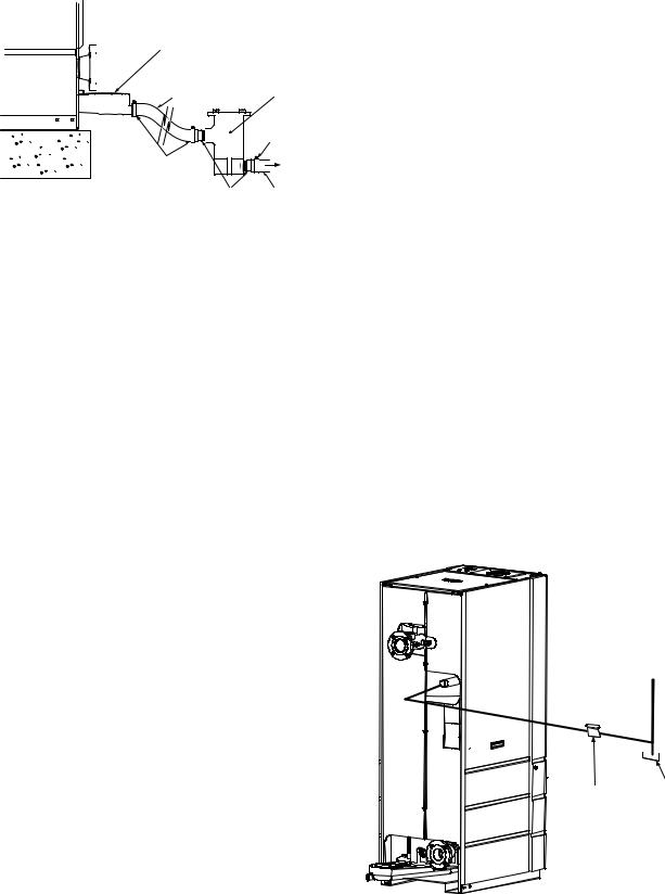
2.7.2 Manual Gas Shutoff Valve
A manual shut-off valve must be installed in the gas supply line upstream of the Boiler as shown in Figure 2-6. Maximum allowable gas pressure to the Boiler is 2 psi
NATURAL
GAS
SUPPLY
1-½” MANUAL |
DIRT |
|
TRAP |
||
GAS SHUTOFF |
||
|
||
VALVE |
|
Figure 2-6
Manual Gas Shut-Off Valve Location
2.7.3 IRI Gas Train Kit
The IRI gas train is an optional gas train configuration which is required in some areas for code compliance or for insurance purposes. The IRI gas train is factory pre-piped and wired. See Appendix F, Drawing AP-A-830 for details.
2.8 AC ELECTRICAL POWER WIRING
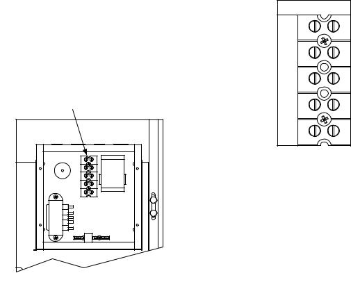
The AERCO Benchmark 1.5 Electrical Power Wiring Guide, GF-4060, must be consulted prior to connecting any AC power wiring to the unit. External AC power connections are made to the unit inside the Power Box on the front panel of the unit. Remove the front door of the unit to access the Power Box mounted directly above the Control Box. Loosen the four Power Box cover screws and remove cover to access the AC terminal connections inside the Power Box (Figure 2-7).
NOTE
All electrical conduit and hardware must be installed so that it does not interfere with the removal of any unit covers, inhibit service/maintenance, or prevent access between the unit and walls or another unit.
Figure 2-7
AC Input Terminal Block Location
INSTALLATION
2.8.1 Electrical Power Requirements
The AERCO Benchmark 1.5 Boiler accepts 120 VAC, single-phase, 60 Hz @ 20 A. The Power Box contains a terminal block as shown in Figure 2-8. In addition, a wiring diagram showing the required AC power connections is provided on the front cover of the Power Box.
Each Benchmark 1.5 Boiler must be connected to a dedicated electrical circuit. NO OTHER DEVICES SHOULD BE ON THE SAME ELECTRICAL CIRCUIT AS THE BENCHMARK BOILER. A means for disconnecting AC power from the unit (such as a service switch) must be installed near the unit for normal operation and maintenance. All electrical connections should be made in accordance with the National Electrical Code and/or with any applicable local codes.
For electrical power wiring diagrams, see the AERCO Benchmark 1.5 Electrical Power Wiring Guide, (GF-4060).
Figure 2-8
AC Terminal Block Configurations
2.9 MODES OF OPERATION AND FIELD CONTROL WIRING
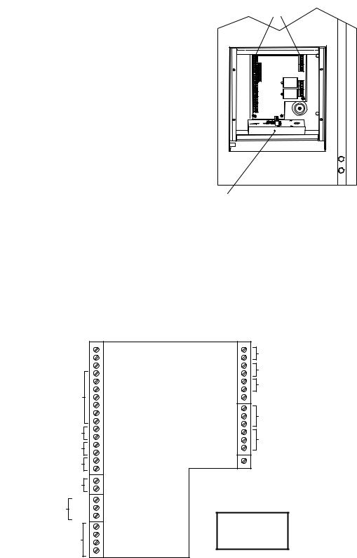
The Benchmark 1.5 Boiler is available in several different modes of operation. While each unit is factory configured and wired for its intended mode, some additional field wiring may be required to complete the installation. This wiring is typically connected to the Input/Output (I/O) Box located on the lower portion of the unit front panel (Figure 2-9) behind the removable front door.
2-5
INSTALLATION
To access the I/O Box terminal strips shown in Figure 2-10, loosen the four cover screws and remove the cover. All field wiring is installed from the rear of the panel by routing the wires through one of the four bushings provided.
Refer to the wiring diagram provided on the cover of the I/O Box (Figure 2-10) when making all wiring connections.
In addition to the terminal strips shown in Figure 2-9, the I/O Box also contains a pre-wired temperature transmitter which receives inlet air temperature sensor readings and transmits this signal to the variable frequency drive (VFD) contained in the Benchmark 1.5 Boiler. The VFD utilizes this input signal to adjust the rotation speed of the blower.
Brief descriptions of each mode of operation, and their wiring requirements, are provided in the following paragraphs. Additional information concerning field wiring is provided in paragraphs 2.9.1 through 2.9.9. Refer to Chapter 5 for detailed information on the available modes of operation.
Figure 2-9.
Input/Output (I/O) Box Location
Figure 2-10. I/O Box Terminal Strip
2-6
2.9.1 Constant Setpoint Mode
The Constant Setpoint Mode is used when it is desired to have a fixed setpoint that does not deviate. No wiring connections, other than AC electrical power connections, are required for this mode. However, if desired, fault monitoring or enable/disable interlock wiring can be utilized (see paragraphs 2.9.9.1 and 2.9.10).
2.9.2 Indoor/Outdoor Reset Mode
This mode of operation increases supply water temperature as outdoor temperatures decrease. An outside air temperature sensor (AERCO Part No. 122790) is required. The sensor MUST BE wired to the I/O Box wiring terminals (see Figure 2-10). Refer to paragraph 2.10.1 for additional information on outside air temperature sensor installation.
2.9.3 Boiler Management System Mode
When using an AERCO Boiler Management System (BMS), the field wiring is connected between the BMS Panel and each Boiler’s I/O Box terminal strip (Figure 2-10). Twisted shielded pair wire from 18 to 22 AWG must be utilized for the connections. The BMS Mode can utilize either pulse width modulation (PWM) signaling, or RS485 Modbus signaling. For PWM signaling, connections are made from the AERCO Boiler Management System to the B.M.S. (PWM) IN terminals on the I/O Box terminal strip. For RS485 Modus signaling, connections are made from the BMS to the RS485 COMM terminals on the I/O Box terminal strip. Polarity must be maintained and the shield must be connected only at the AERCO BMS. The boiler end of the shield must be left floating. For additional instructions, refer to Chapter 5, paragraph 5.6 in this manual. Also, refer to GF108M, BMS -Operations Guide.
2.9.4 Remote Setpoint and Direct Drive Modes
The Benchmark 1.5 Boiler can accept several types of signal formats from an Energy Management System (EMS), Building Automation System (BAS) or other source, to control either the setpoint (Remote Setpoint Mode) or firing rate (Direct Drive Mode) of the Boiler. These formats are:
•4 to 20 mA/1 to 5 VDC
•0 to 20 mA/0 to 5 VDC
•PWM – (Pulse Width Modulated signal. See para. 2.10.4)
•Network (RS485 Modbus. See para. 2.10.7)
INSTALLATION
While it is possible to control a boiler or boilers using one of the previously described modes of operation, it may not be the method best suited for the application. Prior to selecting one of these modes of operation, it is recommended that you consult with your local AERCO representative or the factory for the mode of operation that will work best with your application. For more information on wiring the 4 to 20 mA / 1to 5VDC or the 0 to 20 mA / 0 to 5 VDC, see paragraph 2.9.3.
2.9.5 Combination Mode
With a Combination Mode unit, field wiring is between the unit’s I/O Box wiring terminals, the CCP (Combination Control Panel), and the BMS (Boiler Management System). The wiring must be accomplished using twisted-shielded pair wire from 18 to 22 AWG. Polarity must be maintained. For further instructions and wiring diagrams, refer to the GF-108 Boiler Management System Operations Guide and the CCP-1 data sheet.
2.10 I/O BOX CONNECTIONS
The types of input and output signals and devices to be connected to the I/O Box terminals shown in Figure 2-10 are described in the following paragraphs.
CAUTION
DO NOT make any connections to the I/O Box terminals labeled “NOT USED”. Attempting to do so may cause equipment damage.
2.10.1 OUTDOOR SENSOR IN
An outdoor air temperature sensor (AERCO Part No. 122790) will be required primarily for the Indoor/Outdoor reset mode of operation. It can also be used with another mode if it is desired to use the outdoor sensor enable/disable feature. This feature allows the boiler to be enabled or disabled based on the outdoor air temperature.
The factory default for the outdoor sensor is DISABLED. To enable the sensor and/or select an enable/disable outdoor temperature, see the Configuration menu in Chapter 3.
The outdoor sensor may be wired up to 200 feet from the boiler. It is connected to the OUTDOOR SENSOR IN and SENSOR COMMON terminals in the I/O Box (see Figures 2-9 and 2-10). Wire the sensor using a twisted shielded pair wire from 18 to 22 AWG. There is no polarity to observe when terminating these wires. The shield is to be connected only to the
2-7
INSTALLATION
terminals labeled SHIELD in the I/O Box. The sensor end of the shield must be left free and ungrounded.
When mounting the sensor, it must be located on the North side of the building where an average outside air temperature is expected. The sensor must be shielded from direct sunlight as well as impingement by the elements. If a shield is used, it must allow for free air circulation.
2.10.2 AUX SENSOR IN
The AUX SENSOR IN terminals can be used to add an additional temperature sensor for monitoring purposes. This input is always enabled and is a view-only input that can be seen in the Operating Menu. The sensor must be wired to the AUX SENSOR IN and SENSOR COMMON terminals and must be similar to AERCO BALCO wire sensor Part No. 12449. A resistance chart for this sensor is provided in Appendix C.
2.10.3 ANALOG IN
The ANALOG IN + and – terminals are used when an external signal is used to drive the firing rate (Direct Drive Mode) or change the setpoint (Remote Setpoint Mode) of the Boiler.
Either a 4 to 20 mA /1 to 5 VDC or a 0 to 20 mA / 0 to 5 VDC signal may be used to vary the setpoint or firing rate. The factory default setting is for 4 to 20 mA / 1 to 5 VDC, however this may be changed to 0 to 20 mA / 0 to 5 VDC using the Configuration Menu described in Chapter 3. If voltage rather than current is selected as the drive signal, a DIP switch must be set on the CPU Board located inside the Control Box. Contact the AERCO factory for information on setting DIP switches.
All of the supplied signals must be floating (ungrounded) signals. Connections between the signal source and the Boiler’s I/O Box must be made using twisted shielded pair wire from 18 to 22 AWG, such as Belden 9841 (see Figure 2-10). Polarity must be maintained. The shield must be connected only at the source end and must be left floating (not connected) at the Boiler’s I/O Box.
Regardless of whether voltage or current is used for the drive signal, they are linearly mapped to a 40°F to 240°F setpoint or a 0% to 100% firing rate. No scaling for these signals is provided
2-8
2.10.4 B.M.S. (PWM) IN
These terminals are used to connect the AERCO Boiler Management System (BMS) to the unit. The BMS utilizes a 12 millisecond, ON/OFF duty cycle. This duty cycle is Pulse Width Modulated (PWM) to control firing rate. A 0% firing rate = a 5% ON pulse and a 100% firing rate = a 95% ON pulse.
2.10.5 SHIELD
The SHIELD terminals are used to terminate any shields used on sensor wires connected to the unit. Only shields must be connected to these terminals.
2.10.6 mA OUT
These terminals provide a 4 to 20 mA output to the VFD to control the rotational speed of the blower. This function is enabled in the Configuration Menu (Chapter 3, Table 3.4).
2.10.7 RS-485 COMM
These terminals are used for RS-485 MODBUS serial communication between the unit and an external “Master” such as a Boiler Management System (BMS), Energy Management System (EMS), Building Automation System (BAS) or other suitable device.
2.10.8 EXHAUST SWITCH IN
These terminals permit an external exhaust switch to be connected to the exhaust manifold of the boiler. The exhaust switch should be a normally open type switch (such as AERCO Part No. 123463) that closes (trips) at 500°F.
2.10.9 INTERLOCKS
The unit offers two interlock circuits for interfacing with Energy Management Systems and auxiliary equipment such as pumps or louvers. These interlocks are called the Remote Interlock and Delayed Interlock (Figure 2-10). The wiring terminals for these interlocks are located inside the I/O Box on the unit front panel. The I/O Box cover contains a wiring diagram which shows the terminal strip locations for these interlocks (REMOTE INTL’K IN and DELAYED INTL’K IN). Both interlocks, described below, are factory wired in the closed position.
NOTE
Both the Delayed Interlock and Remote Interlock MUST be in the closed position to allow the unit to fire.
2.10.9.1 REMOTE INTERLOCK IN
The remote interlock circuit is provided to remotely start (enable) and stop (disable) the Boiler, if desired. The circuit is labeled REMOTE INTL’K IN and is located inside the I/O Box on the front panel. The circuit is 24 VAC and is factory pre-wired in the closed (jumpered) position.
2.10.9.2 DELAYED INTERLOCK IN
The delayed interlock is typically used in conjunction with the auxiliary relay described in paragraph 2.10. This interlock circuit is located in the purge section of the start string. It can be connected to the proving device (end switch, flow switch etc.) of an auxiliary piece of equipment started by the Boiler’s auxiliary relay. The delayed interlock must be closed for the boiler to fire.
If the delayed interlock is connected to a proving device that requires time to close (make), a time delay (Aux Start On Dly) that holds the start sequence of the boiler long enough for a proving switch to make can be programmed. Should the proving switch not prove within the programmed time frame, the boiler will shut down. The Aux Start On Dly can be programmed from 0 to 120 seconds. This option is locate in the Configuration Menu (Chapter 3, Table 3-4).
2.10.10 FAULT RELAY
The fault relay is a single pole double throw (SPDT) relay having a normally open and normally closed set of relay contacts that are rated for 5 amps at 120 VAC and 5 amps at 30 VDC. The relay energizes when any fault condition occurs and remains energized until the fault is cleared and the CLEAR button is depressed. The fault relay connections are shown in Figure 2-10.
2.11 AUXILIARY RELAY CONTACTS
Each Boiler is equipped with a single pole double throw (SPDT) relay that is energized when there is a demand for heat and deenergized after the demand for heat is satisfied. The relay is provided for the control of auxiliary equipment, such as pumps and louvers, or can be used as a Boiler status indictor (firing or not firing). Its contacts are rated for 120 VAC @ 5 amps. Refer to Figure 2-10 to locate the AUX RELAY terminals for wiring connections.
INSTALLATION
2.12 FLUE GAS VENT INSTALLATION
The minimum allowable vent diameter for a single Benchmark 1.5 Boiler is 6 inches.
The AERCO Benchmark Venting and Combustion Air Guide, GF-4050, must be consulted before any flue gas vent or inlet air venting is designed or installed. U/L listed, positive pressure, watertight vent materials as specified in AERCO’s GF-4050, must be used for safety and code compliance. Since the unit is capable of discharging low temperature exhaust gases, horizontal sections of the flue vent system must be pitched back to the unit a minimum of 1/4 inch per foot to avoid condensate pooling and allow for proper drainage.
The combined pressure drop of vent and combustion air systems must not exceed 140 equivalent feet of 6 inch ducting. Fittings as well as pipe lengths must be calculated as part of the equivalent length.
For a natural draft installation the draft must not exceed ±0.25 inch W.C. These factors must be planned into the vent installation. If the maximum allowable equivalent lengths of piping are exceeded, the unit will not operate properly or reliably.
2.13 COMBUSTION AIR
The AERCO Benchmark Venting and Combustion Air Guide, GF-4050 MUST be consulted before any flue or combustion supply air venting is designed or implemented. Combustion air supply is a direct requirement of ANSI 223.1, NFPA-54, and local codes. These codes should be consulted before a permanent design is determined.
The combustion air must be free of chlorine, halogenated hydrocarbons, or other chemicals that can become hazardous when used in gasfired equipment. Common sources of these compounds are swimming pools, degreasing compounds, plastic processing and refrigerants. Whenever the environment contains these types of chemicals, combustion air must be supplied from a clean area outdoors for the protection and longevity of the equipment.
2-9
INSTALLATION
The AERCO Benchmark 1.5 Boiler is UL listed for 100% sealed combustion. It can also be installed using room air, provided there is an adequate supply. (See paragraph 2.13.3 for more information concerning sealed combustion air). If the sealed combustion air option is not being used, an inlet screen will be attached at the air inlet on the top of the unit
The more common methods of supplying combustion air are outlined below. For more information concerning combustion air, consult the AERCO Benchmark Venting and Combustion Air Guide, GF-4050.
2.13.1 Combustion Air From Outside the Building
Air supplied from outside the building must be provided through two permanent openings. Each opening must have a free area of not less than one square inch for each 4000 BTU/H boiler input. The free area must take into account restrictions such as louvers and bird screens.
2.13.2 Combustion Air From Inside The Building
When combustion air is provided from within the building, it must be supplied through two permanent openings in an interior wall. Each opening must have a free area of not less than one square inch per 1000 BTU/H of total boiler input. The free area must take into account any restrictions such as louvers.
2.13.3 Sealed Combustion
The AERCO Benchmark 1.5 Boiler is UL listed for 100%-sealed combustion. For sealed combustion installations, the screen on the air inlet duct of the unit must be removed. The inlet air ductwork must then be attached directly to the unit’s air inlet.
In a sealed combustion air application, the combustion air ducting pressure losses must be taken into account when calculating the total maximum allowable venting run. See the AERCO Benchmark Venting and Combustion Air Guide, GF-4050. When using the boiler in a sealed combustion air configuration, each unit must have a minimum 8 inch diameter connection at the unit.
2-10
CONTROL PANEL OPERATING PROCEDURES
CHAPTER 3 CONTROL PANEL OPERATING PROCEDURES
3.1 INTRODUCTION
The information in this Chapter provides a guide to the operation of the Benchmark 1.5 Boiler using the Control Panel mounted on the front of the unit. It is imperative that the initial startup of this unit be performed by factory trained personnel. Operation prior to initial startup by factory trained personnel will void the equipment warranty. In addition, the following WARNINGS and CAUTIONS must be observed at all times.
CAUTION
All of the installation procedures in Chapter 2 must be completed before attempting to start the unit.
WARNING
ELECTRICAL VOLTAGES IN THIS
SYSTEM MAY INCLUDE 460, 208
AND 24 VOLTS AC. IT MUST BE
SERVICED ONLY BY FACTORY
CERTIFIED SERVICE TECHNICIANS
WARNING
DO NOT ATTEMPT TO DRY FIRE THE BOILER. STARTING THE UNIT WITHOUT A FULL WATER LEVEL CAN SERIOUSLY DAMAGE THE UNIT AND MAY RESULT IN INJURY TO PERSONNEL OR PROPERTY DAMAGE. THIS SITUATION WILL VOID ANY WARRANTY.
3.2 CONTROL PANEL DESCRIPTION
The Benchmark 1.5 Control Panel shown in Figure 3-1 contains all of the controls, indicators and displays necessary to operate, adjust and troubleshoot the Benchmark 1.5 Boiler. These operating controls, indicators and displays are listed and described in Table 3-1. Additional information on these items are provided in the individual operating procedures provided in this Chapter.
Figure 3-1.
Control Panel Front View
3-1
CONTROL PANEL OPERATING PROCEDURES
Table 3-1 Operating Controls, Indicators and Displays
ITEM |
CONTROL, INDICATOR |
|
|
NO. |
OR DISPLAY |
FUNCTION |
|
1 |
LED Status Indicators |
Four Status LEDs indicate the current operating status as |
|
|
|
follows: |
|
|
COMM |
Lights when RS-232 communication is occurring |
|
|
MANUAL |
Lights when the unit is being controlled using the front panel |
|
|
|
keypad. |
|
|
REMOTE |
Lights when the unit is being controlled by an external signal |
|
|
|
from an Energy Management System |
|
|
DEMAND |
Lights when there is a demand for heat. |
|
|
|
|
|
2 |
OUTLET |
3–Digit, 7–Segment LED display continuously displays the |
|
|
TEMPERATURE |
outlet water temperature. The °F or °C LED next to the |
|
|
Display |
display lights to indicate whether the displayed temperature is |
|
|
|
in degrees Fahrenheit or degrees Celsius. |
|
3 |
VFD Display |
Vacuum Fluorescent Display (VFD) consists of 2 lines each |
|
|
|
capable of displaying up to 16 alphanumeric characters. The |
|
|
|
information displayed includes: |
|
|
|
Startup Messages |
|
|
|
Fault Messages |
|
|
|
Operating Status Messages |
|
|
|
Menu Selection |
|
|
|
|
|
4 |
RS-232 Port |
Port permits a Laptop Computer or External Modem to be |
|
|
|
connected to the unit’s Control Panel. |
|
|
|
|
|
5 |
FAULT Indicator |
Red FAULT LED indicator lights when a boiler alarm |
|
|
|
condition occurs. An alarm message will appear in the VFD. |
|
6 |
CLEAR Key |
Turns off the FAULT indicator and clears the alarm message |
|
|
|
if the alarm is no longer valid. Lockout type alarms will be |
|
|
|
latched and cannot be cleared by simply pressing this key. |
|
|
|
Troubleshooting may be required to clear these types of |
|
|
|
alarms. |
|
7 |
READY Indicator |
Lights ON/OFF switch is set to ON and all Pre-Purge |
|
conditions have been satisfied. |
|||
|
|
||
|
|
|
|
8 |
ON/OFF Switch |
Enables and disables boiler operation. |
|
9 |
LOW WATER LEVEL |
Allows operator to test operation of the water level monitor. |
|
|
TEST/RESET Switches |
Pressing TEST opens the water level probe circuit and |
|
|
|
simulates a Low Water Level alarm. |
|
|
|
Pressing RESET resets the water level monitor circuit. |
|
|
|
Pressing the CLEAR key (item 6) resets the display. |
|
|
|
|
3-2
CONTROL PANEL OPERATING PROCEDURES
Table 3-1 Operating Controls, Indicators and Displays – Continued
ITEM |
CONTROL, INDICATOR |
|
NO. |
OR DISPLAY |
FUNCTION |
10 |
MENU Keypad |
Consists of 6 keys which provide the following functions for |
|
|
the Control Panel Menus: |
|
MENU |
Steps through the main menu categories shown in Figure 3- |
|
|
2. The Menu categories wrap around in the order shown. |
|
BACK |
Allows you to go back to the previous menu level without |
|
|
changing any information. Continuously pressing this key |
|
|
will bring you back to the default status display in the VFD. |
|
|
Also, this key allows you to go back to the top of a main |
|
|
menu category. |
|
▲ (UP) Arrow |
When in one of the main menu categories (Figure 3-2), |
|
|
pressing the ▲ arrow key will select the displayed menu |
|
|
category. If the CHANGE key was pressed and the menu |
|
|
item is flashing, pressing the ▲ arrow key will increment the |
|
|
selected setting. |
|
▼ (DOWN) Arrow |
When in one of the main menu categories (Figure 3-2), |
|
||
|
|
pressing this key will select the displayed menu category. If |
|
|
the CHANGE key was pressed and the menu item is |
|
|
flashing, pressing the ▼ arrow key will decrement the |
|
|
selected setting. |
|
CHANGE |
Permits a setting to be changed (edited). When the |
|
|
CHANGE key is pressed, the displayed menu item will begin |
|
|
to flash. Pressing the ▲ or ▼ arrow key when the item is |
|
|
flashing will increment or decrement the displayed setting. |
|
ENTER |
Saves the modified menu settings in memory. The display |
|
|
will stop flashing. |
|
|
|
11 |
AUTO/MAN Switch |
This switch toggles the boiler between the Automatic and |
|
|
Manual modes of operation. When in the Manual (MAN) |
|
|
mode, the front panel controls are enabled and the |
|
|
MANUAL status LED lights. |
|
|
When in the Automatic (AUTO) mode, the MANUAL status |
|
|
LED will be off and the front panel controls disabled. |
12 |
FIRE RATE Bargraph |
20 segment red LED bargraph continuously shows the Fire |
|
|
Rate in 5% increments from 0 to 100% |
|
|
|
3-3
CONTROL PANEL OPERATING PROCEDURES
3.3 CONTROL PANEL MENUS
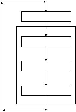
The Control Panel incorporates an extensive menu structure which permits the operator to set up, and configure the unit. The menu structure consists of four major menu categories as shown in Figure 3-2. Each of the menus shown, contain options which permit operating parameters to be viewed or changed. The menus are protected by a password to prevent unauthorized use.
Prior to entering the correct password, the options contained in the Operating, Setup, Configuration and Tuning Menu categories can be viewed. However, with the exception of Internal Setpoint Temperature (Configuration Menu), none of the viewable menu options can be changed.
Once the valid password (159) is entered, the options listed in the Setup. Configuration and Tuning Menus can be viewed and changed, if desired.
3.3.1Menu Processing Procedure
Accessing and initiating each menu and option is accomplished using the Menu Keys shown in Figure 3-1. Therefore, it is imperative that you be thoroughly familiar with the following basic steps before attempting to perform specific menu procedures.
1.The Control Panel will normally be in the Operating Menu and the VFD will display the current unit status. Pressing the ▲ or ▼ arrow key will display the other available data items in the Operating Menu.
2.Press the MENU key. The display will show the Setup Menu, which is the next menu category shown in Figure 3-2. This menu contains the Password option which must be entered if other menu options will be changed.
3.Continue pressing the MENU key until the desired menu is displayed.
4.With the desired menu displayed, press the ▲ or ▼ arrow key. The first option in the selected menu will be displayed.
5.Continue to press the ▲ or ▼ arrow key until the desired menu option is displayed. Pressing the ▲ arrow key will display the available menu options in the Top-Down sequence. Pressing the ▼ arrow key will display the options in the Bottom-Up sequence. The menu options will wrap-
3-4
around after the first or last available option is reached.
6.To change the value or setting of a displayed menu option, press the CHANGE key. The displayed option will begin to flash. Press the ▲ or ▼ arrow key to scroll through the available menu option choices for the option to be changed. The menu option choices do not wrap around.
7.To select and store a changed menu item, press the ENTER key.
Figure 3-2. Menu Structure
NOTE
The following paragraphs provide brief descriptions of the options contained in each menu. Refer to Appendix A for detailed descriptions of each menu option. Refer to Appendix B for listings and descriptions of displayed startup, status and error messages.
CONTROL PANEL OPERATING PROCEDURES
3.4 OPERATING MENU
The Operating Menu displays a number of key operating parameters for the unit as listed in Table 3-2. This menu is “Read-Only” and does not allow personnel to change or adjust any displayed items. Since this menu is “Read-Only”, it can be viewed at any time without entering a password. Pressing the ▲ arrow key to display the menu items in the order listed (Top-Down). Pressing the ▼ arrow key will display the menu items in reverse order (Bottom-Up).
3.5 SETUP MENU
The Setup Menu (Table 3-3) permits the operator to enter the unit password (159) which is required to change the menu options. To prevent unauthorized use, the password will
time-out after 1 hour. Therefore, the correct password must be reentered when required. In addition to permitting password entries, the Setup Menu is also used to enter date and time, units of temperature measurements and entries required for external communication and control of the unit via the RS-232 port. A view-only software version display is also provided to indicate the current Control Box software version.
NOTE
The Outdoor Temp display item shown with an asterisk in Table 3-2 will not be displayed unless the Outdoor Sensor function has been enabled in the Configuration Menu (Table 3-4).
Table 3-2. Operating Menu
|
Available Choices or Limits |
|
|
Menu Item Display |
Minimum |
Maximum |
Default |
|
|
|
|
Status Message |
|
|
|
|
|
|
|
Active Setpoint |
40°F |
240°F |
|
|
|
|
|
Aux Temp |
30°F |
245°F |
|
|
|
|
|
Outdoor Temp* |
-70°F |
130°F |
|
|
|
|
|
Fire Rate In |
0% |
Max Fire Rate |
|
|
|
|
|
Flame Strength |
0% |
100% |
|
|
|
|
|
Run Cycles |
0 |
999,999 |
|
|
|
|
|
Run Hours |
0 |
999,999 |
|
|
|
|
|
Fault Log |
0 |
9 |
0 |
|
|
|
|
Table 3-3. Setup Menu
|
Available Choices or Limits |
|
||
Menu Item Display |
Minimum |
|
Maximum |
Default |
Passsword |
0 |
|
9999 |
0 |
|
|
|
|
|
Language |
English |
|
English |
|
|
|
|
|
|
Time |
12:00 am |
|
11:59 pm |
|
|
|
|
|
|
Date |
01/01/00 |
|
12/31/99 |
|
|
|
|
|
|
Unit of Temp |
Fahrenheit or Celsius |
Fahrenheit |
||
|
|
|
|
|
Comm Address |
0 |
|
127 |
0 |
|
|
|
|
|
Baud Rate |
2400, 4800, 9600, 19.2K |
9600 |
||
|
|
|
|
|
Software |
Ver 0.00 |
|
Ver 9.99 |
|
|
|
|
|
|
3-5
CONTROL PANEL OPERATING PROCEDURES
3.6 CONFIGURATION MENU |
NOTE |
The Configuration Menu shown in Table 3-4 permits adjustment of the Internal Setpoint (Setpt) temperature regardless of whether the valid password has been entered. Setpt is required for operation in the Constant Setpoint mode. The remaining options in this menu require the valid password to be entered, prior to changing existing entries. This menu contains a number of other configuration settings which may or may not be displayed, depending on the current operating mode setting.
The Configuration Menu settings shown in Table 3-4 are Factory-Set in accordance with the requirements specified for each individual order. Therefore, under normal operating conditions, no changes will be required.
Table 3-4. Configuration Menu
|
Available Choices or Limits |
|
||
Menu Item Display |
Minimum |
Maximum |
Default |
|
Internal Setpt |
Lo Temp Limit |
Hi Temp Limit |
130°F |
|
|
|
|
|
|
Unit Type |
Boiler or Water Heater |
Boiler |
||
|
|
|
||
Unit Size |
0.5 MBTU, 1.0 MBTU |
1.0 MBTU |
||
|
1.5 MBTU, 2.0 MBTU |
|
||
|
2.5 MBTU, 3.0 MBTU |
|
||
Boiler Mode |
Constant Setpoint, |
Constant |
||
|
Remote Setpoint, |
Setpoint |
||
|
Direct Drive |
|
||
|
Combination |
|
||
|
Outdoor Reset |
|
||
|
|
|
||
Remote Signal |
4 – 20 mA/1 – 5V |
4 – 20 mA, |
||
(If Mode = Remote |
0 -20 mA/0 – 5V |
1-5V |
||
Setpoint, Direct Drive |
PWM Input (BMS) |
|||
|
||||
or Combination) |
Network |
|
||
|
|
|
|
|
Bldg Ref Temp |
40°F |
230°F |
70°F |
|
(If Mode = Outdoor |
|
|
|
|
Reset) |
|
|
|
|
Reset Ratio |
0.1 |
9.9 |
1.2 |
|
(If Mode = Outdoor |
|
|
|
|
Reset) |
|
|
|
|
|
|
|
|
|
Outdoor Sensor |
Enabled or Disabled |
Disabled |
||
|
|
|
|
|
System Start Tmp |
30°F |
100°F |
60°F |
|
(If Outdoor Sensor = |
|
|
|
|
Enabled) |
|
|
|
|
|
|
|
|
|
Setpt Lo Limit |
40°F |
Setpt Hi Limit |
60°F |
|
|
|
|
|
|
Setpt Hi Limit |
Setpt Lo Limit |
220°F |
200°F |
|
|
|
|
|
|
Temp Hi Limit |
40°F |
240°F |
210°F |
|
|
|
|
|
|
Max Fire Rate |
40% |
100% |
100% |
|
|
|
|
|
|
Pump Delay Timer |
0 min. |
30 min. |
0 min. |
|
|
|
|
|
|
Aux Start On Dly |
0 sec. |
120 sec. |
0 sec. |
|
|
|
|
|
|
3-6
CONTROL PANEL OPERATING PROCEDURES
Table 3-4. Configuration Menu - Continued
|
Available Choices or Limits |
|
|
Menu Item Display |
Minimum |
Maximum |
Default |
Failsafe Mode |
Shutdown or Constant Setpt |
Shutdown |
|
|
|
|
|
*mA Output |
Setpoint, Outlet Temp, |
*Fire Rate |
|
(See CAUTION) |
Fire Rate Out, Off |
Out |
|
Low Fire Timer |
2 sec. |
120 sec. |
2 sec. |
|
|
|
|
Setpt Limiting |
Enabled or Disabled |
Disabled |
|
|
|
|
|
Setpt Limit Band |
0°F |
10°F |
5°F |
|
|
|
|
*CAUTION: DO NOT CHANGE mA Output Menu Item from its Default setting.
3.7 TUNING MENU
The Tuning Menu items in Table 3-5 are Factory set for each individual unit. Do not change these menu entries unless specifically requested to do so by Factory-Trained personnel.
Table 3-5. Tuning Menu
|
Available Choices or Limits |
|
||
Menu Item Display |
Minimum |
|
Maximum |
Default |
Prop Band |
1°F |
|
120°F |
70°F |
|
|
|
|
|
Integral Gain |
0.00 |
|
2.00 |
1.00 |
|
|
|
|
|
Derivative Time |
0.0 min |
|
2.00 min |
0.00 min |
|
|
|
|
|
Reset Defaults? |
|
Yes |
No |
|
|
|
No |
|
|
|
Are You Sure? |
|
||
3.8 START SEQUENCE
When the Control Box ON/OFF switch is set to the ON position, it checks all pre-purge safety switches to ensure they are closed. These switches include:
•Safety Shut-Off Valve Proof of Closure (POC) switch
•Low Water Level switch
•High Water Temperature switch
When there is a demand for heat, the following events will occur:
NOTE
If any of the Pre-Purge safety device switches are open, the appropriate fault message will be displayed. Also, the appropriate fault messages will be displayed throughout the start sequence, if the required conditions are not observed.
•High Gas Pressure switch
•Low Gas Pressure switch
•Blower Proof switch
If all of the above switches are closed, the READY light above the ON/OFF switch will light and the unit will be in the Standby mode.
1.The DEMAND LED status indicator will light.
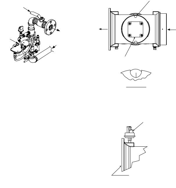
2.The unit checks to ensure that the Proof of Closure (POC) switch in the downstream Safety Shut-Off Valve (SSOV) is closed. See Figure 3-3 for SSOV locations.
3-7
CONTROL PANEL OPERATING PROCEDURES
Figure 3-3.
SSOV Locations
3.With all required safety device switches closed, a purge cycle will be initiated and the following events will occur:
(a)The Blower relay energizes and turns on blower.
(b)The Air/Fuel Valve rotates to the fullopen purge position and closes purge position switch. The dial on the Air/Fuel Valve (Figure 3-4) will read 100 to indicate that it is full-open (100%).
(c)The FIRE RATE bargraph will show 100%.
4.Next, the blower proof switch on the Air/Fuel Valve (Figure 3-5) closes. The display will show Purging and indicate the elapsed time of the purge cycle in seconds. The normal (default) time for the purge cycle is 7 seconds.
5.Upon completion of the purge cycle, the Control Box initiates an ignition cycle and the following events occur:
(a)The Air/Fuel Valve rotates to the lowfire ignition position and closes the ignition switch. The dial on the Air/Fuel Valve (Figure 3-6) will read between 25 and 35 to indicate that the valve is in the low-fire position.
(b)The igniter relay is activated and provides ignition spark.
(c)The gas Safety Shut-Off Valve (SSOV) is energized (opened) allowing gas to flow into the Air/Fuel Valve.
DIAL (DETAIL “A”)
STEPPER
MOTOR
100
DETAIL “A”
Figure 3-4.
Air/Fuel Valve In Purge Position
Figure 3-5.
Blower Proof Switch
6.Up to 7 seconds will be allowed for ignition to be detected. The igniter relay will be turned off one second after flame is detected.
7.After 2 seconds of continuous flame, Flame Proven will be displayed and the flame strength will be indicated. After 5 seconds, the current date and time will be displayed in
place of the flame strength.
3-8
CONTROL PANEL OPERATING PROCEDURES
8.With the unit firing properly, it will be controlled by the temperature controller circuitry. The boiler’s FIRE RATE will be continuously displayed on the front panel bargraph.
Once the demand for heat has been satisfied, the Control Box will turn off the dual SSOV gas valves. The blower relay will be deactivated and the Air/Fuel Valve will be closed. Standby will be displayed.
DIAL (DETAIL “A”)
STEPPER
MOTOR
52 
DETAIL “A”
Figure 3-6.
Air/Fuel Valve In Ignition
3.9 START/STOP LEVELS
The start and stop levels are the fire rate percentages that start and stop the unit, based on load. These levels are Factory preset as follows:
Start Level: 20%
Stop Level: 16%
Normally, these settings should not require adjustment.
Note that the energy input of the boiler is not linearly related to the fire rate percentage (Air/Fuel Valve position). Refer to Table 3-6 on the following page for the relationship between the energy input and fire rate percentage for a unit running on natural gas.
3-9
CONTROL PANEL OPERATING PROCEDURES
Table 3-6.
Relationship Between Air/Fuel Valve Position and Energy Input For Unit Running On Natural Gas
Fire Rate, |
|
|
Air/Fuel Valve |
Energy Input |
Boiler Energy Input |
Position |
||
(% Open) |
(BTU/Hr) |
(% of Full Capacity) |
|
|
|
0% |
0 |
0 |
10% |
0 |
0 |
16 % |
75,000 |
5.0% |
(Stop Level) |
|
|
20% |
157,000 |
10% |
|
|
|
30% |
310,000 |
21% |
|
|
|
40% |
534,000 |
36% |
50% |
783,000 |
52% |
60% |
970,000 |
65% |
|
|
|
70% |
1,140,000 |
76% |
|
|
|
80% |
1,240,000 |
83% |
90% |
1,370,000 |
91% |
|
|
|
100% |
1,500,000 |
100% |
|
|
|
3-10
 Loading...