

Page 1
Instruction
No.
AERCO INTERNATIONAL, Inc. Northvale, New Jersey, 07647 USA
User’s
Manual
Esteem 399
GF-125U
Low NOx
Gas Fired
Boiler
Visit www.aerco.com to View the Latest
Product Manuals and Information.
Printed in U.S.A. REVISED MAY 2010
Page 2

Telephone Support
(800) 526-0288
Direct to AERCO Technical Support
(8 to 5 pm EST, Monday through Friday)
Please have the unit’s model number and
the serial number from the rating label on
the backside of the control panel when
calling about service or troubleshooting.
Model #_________________________
Serial #__________________________
AERCO International, Inc.
159 Paris Avenue
Northvale, NJ 07647-0128
www.aerco.com
© AERCO International, Inc., 2010
The information contained in this document
is subject to change without notice from
AERCO International, Inc.
AERCO makes no warranty of any kind
with respect to this material, including but
not limited to implied warranties of merchantability and fitness for a particular
application. AERCO International is not liable for errors appearing in this manual. Nor
for incidental or consequential damages
occurring in connection with the furnishing,
performance, or use of this material.
Page 3

Contents—GF-125U
Warnings and Cautions 1
Emergency Shutdown 2
Prolonged Shutdown 2
Boiler & System Water 2
Chapter 1 Combustion Air 3
Prevention of Contamination 3
Potential Contaminating Products 3
Areas likely to have these products 3
Chapter 2 Maintenance Schedule 4
For the Service Technician 4
For the End User 4
Chapter 3 Maintenance Procedures 5
Daily Maintenance 5
Monthly Maintenance 6
Every 6 Months Maintenance 7
Contents
Chapter 4 Operating Instructions 9
Safety 9
TO TURN OFF GAS TO APPLIANCE 10
Operation 10
Standby Mode 11
Chapter 5 BOILER CONTROL DISPLAY 11
Setting Boiler Parameters 12
Accessing Boiler Information 13
Error (Hard Lockout) Mode 14
Boiler Freeze Protection Feature 14
Appendix A: Replacement Parts 15
Jacket Components 15
Internal Components 16
Burner Components 17
Electronic Components 18
Page 4

Warnings and Cautions
Installers and operating personnel
MUST, at all times, observe all safety
regulations.
The following general warnings and cautions
must be given the same attention as specific
precautions included in these instructions. In
addition to the requirements included in this
Manual, the installation MUST conform with
local building codes, or, in the absence of
local codes, ANSI Z223.1 (National Fuel Gas
Code Publication No. NFPA-54). Where ASME
CSD-1 is required by local jurisdiction, the
installation must conform to CSD-1.
Where applicable, the equipment must be
installed in accordance with the current
Installation Code for Gas Burning Appliances
and Equipment, CGA B149, and applicable
Provincial regulations for the class. Authorities
having jurisdiction should be consulted before
installations are made.
CAUTIONS!
Must be observed to prevent damage or
loss of operating effectiveness.
NOTICE
Indicates special instructions on installation, operation or maintenance, which
are important to equipment but not related to personal injury hazards.
WARNING!
BEFORE ATTEMPTING TO PERFORM ANY MAIN-
TENANCE ON THE UNIT, SHUT OFF ALL GAS AND
ELECTRICAL INPUTS TO THE UNIT.
WARNING!
THE EXHAUST VENT PIPE OF THE UNIT OPER-
ATES UNDER A POSITIVE PRESSURE AND THERE-
FORE MUST BE COMPLETELY SEALED TO PRE-
VENT LEAKAGE OF COMBUSTION PRODUCTS INTO
LIVING SPACES.
IMPORTANT
This Instruction Manual is an integral part
of the product and must be maintained in
legible condition. It must be given to the
user by the installer and kept in a safe
place for future reference.
DANGER!
INDICATES THE PRESENCE OF A HAZARDOUS
SITUATION WHICH, IF IGNORED, WILL RESULT IN
DEATH, SERIOUS INJURY OR SUBSTANTIAL PROP-
ERTY DAMAGE.
WARNINGS!
MUST BE OBSERVED TO PREVENT SERIOUS IN-
JURY OR SUBSTANTIAL PROPERTY DAMAGE.
WARNING!
FLUIDS UNDER PRESSURE MAY CAUSE INJURY
OR DAMAGE TO EQUIPMENT WHEN RELEASED.
E SURE TO SHUT OFF ALL INCOMING AND OUT-
B
GOING WATER SHUT OFF VALVES. CAREFULLY
DECREASE ALL TRAPPED PRESSURES TO ZERO
BEFORE PERFORMING ANY BOILER MAINTE-
NANCE.
WARNING!
DO NOT USE MATCHES, CANDLES, FLAMES, OR
OTHER SOURCES OF IGNITION TO CHECK FOR
GAS LEAKS.
CAUTION!
Many soaps used for gas pipe leak testing are corrosive to metals. The piping
must be rinsed thoroughly with clean
water after leak checks have been completed.
GF-125U
1
Page 5
Emergency Shutdown
CAUTION!
DO NOT use this boiler if any part
has been under water. Call a qualifi ed
service technician to inspect and replace any part that has been under-
water.
IMPORTANT
The Installer must identify and indicate the location of the emergency
shutdown manual gas valve to operating personnel.
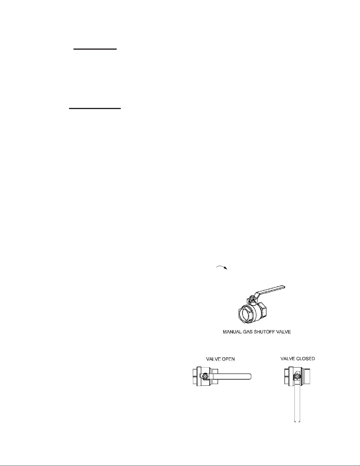
Emergency Shutdown
If overheating occurs or the gas supply fails
to shut off, DO NOT turn off or disconnect
the electrical supply to the pump. Close the
manual gas shutoff valve (Figure 1) located
external to the unit.
Prolonged Shutdown
After prolonged shutdown, the startup procedures in the Installation and Maintenance
Manual should be followed, to verify all system operating parameters.
Boiler & System Water
• Have the boiler and system water chemistry checked at least annually by a qualified
service technician.
• Do not use petroleum-based cleaning or
sealing compounds in the boiler or system.
Gaskets and seals in the system may be
damaged. This can result in substantial
property damage.
• Do not use any product not specifically
designed for boiler / hydronic heating systems. Serious damage to the unit, piping
system, personnel and / or property may
result.
• Continual fresh makeup water will reduce
the life of the Esteem. Addition of oxygen
can cause internal corrosion in the system
components. All leaks in the piping system must be repaired at once to prevent
makeup water.
• Do not add cold water to a hot unit.
Thermal shock can cause premature failure to the boiler heat exchanger.
To shut Down the Unit
Operating Cautions
• Do not block flow of combustion air. If
a blockage should occur and is easily accessible and removable, remove
it. If blockage is not obvious or cannot
be removed, have the unit and system
checked by a qualified service technician.
• Do not allow contaminated air to enter
the unit’s combustion air inlet. See page
3 for details.
• The Esteem is equipped with a low
water cutoff device (LWCO). The boiler
and system piping must be filled and
pressurized to 12 psig prior to startup.
The unit will shut down if the pressure
falls below 10 psig.
Turn the external manual gas valve handle
clockwise to “CLOSE”.
Figure 1: Typical Manual Gas Shutoff Valve
2
GF-125U
Page 6

Prevention of Contamination
Chapter 1 Combustion Air
Prevention of Contamination
WARNING!
IF THE ESTEEM COMBUSTION AIR INLET IS
LOCATED IN ANY AREA LIKELY TO CAUSE OR
CONTAIN CONTAMINATION, OR IF PRODUCTS,
WHICH WOULD CONTAMINATE THE AIR CAN-
NOT BE REMOVED, THE COMBUSTION AIR
MUST BE RE-PIPED AND TERMINATED TO AN-
OTHER LOCATION. CONTAMINATED COMBUS-
TION AIR WILL DAMAGE THE UNIT AND ITS
BURNER SYSTEM, RESULTING IN POSSIBLE
SEVERE PERSONAL INJURY, DEATH OR SUB-
STANTIAL PROPERTY DAMAGE.
ARNING!DO NOT OPERATE A ESTEEM UNIT
W
IF ITS COMBUSTION AIR INLET OR THE UNIT IS
LOCATED IN OR NEAR A LAUNDRY ROOM OR
POOL FACILITY. THESE AREAS WILL ALWAYS
CONTAIN HAZARDOUS CONTAMINATES.
Pool and laundry products and common
household and hobby products often contain
fluorine or chlorine compounds. When these
chemicals pass through the burner and
vent system, they can form strong acids.
These acids can create corrosion of the heat
exchanger, burner components and vent
system, causing serious damage and presenting a possible threat of flue gas spillage
or water leakage into the surrounding area.
Please read the following information. If contaminating chemicals will be present near
the location of the combustion air inlet, the
installer should pipe the combustion air inlet
to another location per the Esteem installation manual.
Potential Contaminating Products
• Spray cans containing chloro/fluorocarbons
• Permanent wave solutions
• Chlorinated wax
• Chlorine - based swimming pool chemicals and spa cleaners
• Calcium chloride used for thawing ice
• Sodium chloride used for water softening
• Refrigerant leaks
• Paint or varnish removers
• Hydrochloric acid / muriatic acid
• Cements and glues
• Antistatic fabric softeners used in
clothes dryers
• Chlorine-type bleaches, detergents, and
cleaning solvents found in household
laundry rooms
• Adhesives used to fasten building products and other similar products
Areas likely to have these
products
• Dry cleaning / laundry areas and establishments
• Beauty salons
• Metal fabrication shops
• Swimming pools and health spas
• Refrigeration Repair shops
• Photo processing plants
• Auto body shops
• Plastic manufacturing plants
• Furniture refinishing areas and establishments
• New building construction
• Remodeling areas
• Garages and workshops
GF-125U
The above lists are NOT comprehensive.
Installer, the end user and service personnel are responsible for certifying the safety
of any and all materials that may affect the
quality of the combustion air.
3
Page 7

For the Service Technician
Chapter 2 Maintenance Schedule
For the Service Technician
On an annual basis, or more frequently if
conditions warrant, the following maintenance should be performed by a qualified
service technician:
General
• Attend to any reported problems.
• Inspect the interior of the boiler jacket
area; clean and vacuum if necessary.
• Clean the condensate trap and fill with
fresh water.
• Check for leaks: water, gas, flue and
condensate.
• Verify flue vent piping and air inlet piping
are in good condition and sealed tight.
• Check boiler water pressure, piping and
expansion tank.
• Check control settings.
• Check ignition electrode (sand off any
white oxide; clean and reposition).
• Check ignition wiring and ground wiring.
• Check all control wiring and connections.
• Check burner flame pattern (stable and
uniform).
Additional items if combustion or performance is poor:
For the End User
• Ongoing, as local conditions warrant.
• Check the area around the unit.
• Check and remove any blockage from
the combustion air inlet and ventilation
openings.
• Check the temperature/pressure gauge.
Monthly:
• Check vent piping.
• Check combustion air inlet piping.
• Check the pressure relief valve.
• Check the condensate drain system.
Every 6 months:
• Check boiler piping and gas supply piping for corrosion or potential signs of
leakage.
• Operate the pressure relief valve.
WARNING!
FOLLOW THE MAINTENANCE PROCEDURES
GIVEN THROUGHOUT THIS MANUAL. FAILURE
TO PERFORM THE SERVICE AND MAINTENANCE
OR FOLLOW THE DIRECTIONS IN THIS MANUAL
COULD RESULT IN DAMAGE TO THE ESTEEM
OR IN SYSTEM COMPONENTS, RESULTING IN
SEVERE PERSONAL INJURY, DEATH OR SUB-
STANTIAL PROPERTY DAMAGE.
• Clean heat exchanger and flue ways.
• Remove burner assembly and clean
burner head using compressed air only.
Once the maintenance items are completed,
review the service with the owner.
4
GF-125U
Page 8

Chapter 3 Maintenance Procedures
Daily Maintenance
WARNING!
THE ESTEEM MUST BE INSPECTED AND
SERVICED ANNUALLY, PREFERABLY AT THE
START OF THE HEATING SEASON, BY A QUALI-
FIED SERVICE TECHNICIAN. IN ADDITION, THE
MAINTENANCE AND CARE OF THE BOILER AS
EXPLAINED IN THIS MANUAL MUST BE PER-
FORMED TO ASSURE MAXIMUM EFFICIENCY
AND RELIABILITY. FAILURE TO SERVICE AND
MAINTAIN THE ESTEEM AND THE SYSTEM
COMPONENTS COULD RESULT IN EQUIPMENT
FAILURE, CAUSING POSSIBLE PERSONAL IN-
JURY, DEATH OR PROPERTY DAMAGE.
Daily Maintenance
Check the Surrounding Area
WARNING!
TO REDUCE POTENTIAL OF SEVERE PERSONAL
INJURY, DEATH OR SUBSTANTIAL PROPERTY
DAMAGE, ELIMINATE ALL THE MATERIALS LIST-
ED ON PAGE 2 FROM THE AREA SURROUND-
ING THE UNIT AND FROM THE VICINITY OF THE
COMBUSTION AIR INLET.
F CONTAMINANTS HAVE BEEN NEAR THE UNIT
I
OR AIR INLET FOR AN EXTENDED PERIOD,
CALL A QUALIFIED SERVICE TECHNICIAN TO
INSPECT THE UNIT FOR POSSIBLE ACID COR-
ROSION DAMAGE.
F PRODUCTS CANNOT BE REMOVED, IMME-
I
DIATELY CALL A QUALIFIED SERVICE TECHNI-
CIAN TO RE-PIPE THE AIR INLET PIPING AND
RELOCATE IT AWAY FROM THE CONTAMINAT-
ED AREAS.
materials listed on page 2 of this manual.
If any of these products are in the room
from which the unit takes its combustion air,
they must be removed immediately or the
combustion air intake must be relocated to
another area.
Check Combustion Air Inlets
• Verify that ventilation air openings to the
mechanical room are open and unobstructed.
• Verify that the unit’s vent termination
and combustion air intake are clean and
free of obstructions. Remove any debris
on the air intake or flue exhaust openings. If removing the debris does not
allow the unit to operate correctly, contact your qualified service technician to
inspect the unit and the vent / combustion air system.
Check Temperature Display and Pressure
Gauge
• Ensure the pressure reading on the
pressure gauge does not exceed 25
psig. Higher pressure readings may indicate a problem with the expansion tank.
• Ensure the temperature on the display
panel does not exceed 194ºF. Higher
temperature readings may indicate a
problem with the operating thermostat
controls.
• Contact a qualified service technician if
problem persists.
Combustible / flammable materials - Do not
store combustible materials, gasoline or
other flammable vapors or liquids near the
unit. Remove immediately if found.
Air contaminates - Products containing chlorine or fluorine, if allowed to contaminate the
combustion air, will cause acidic condensate
within the unit. This will cause significant
damage to the unit. Read the list of potential
GF-125U
5
Page 9

Monthly Maintenance
Monthly Maintenance
Check Vent Piping
• Visually inspect the flue gas vent piping for any signs of blockage, leakage
or deterioration of the piping. Notify a
qualified service technician immediately
if any problems are found.
WARNING!
FAILURE TO INSPECT THE VENTING SYSTEM
AS NOTED AND HAVE IT REPAIRED BY A QUALI-
FIED SERVICE TECHNICIAN CAN RESULT IN
THE VENT SYSTEM FAILURE, CAUSING SEVERE
PERSONAL INJURY OR DEATH.
Check Combustion Air Inlet Piping
• Visually inspect the combustion air inlet
piping for any signs of blockage. Inspect
the entire length of the combustion air
inlet piping to ensure piping is intact and
all joints are properly sealed.
• Notify a qualified service technician if
any problems are found.
Check Pressure Relief Valve
• Visually inspect the primary pressure
relief valve and the relief valve discharge pipe for signs of weeping or
leakage.
• If the pressure relief valve often weeps,
the expansion tank may not be operating properly. Immediately contact a
qualified service technician to inspect
the unit and system.
Check Vent Condensate Drain System
• While the unit is running, check the discharge end of the condensate drain tubing. Ensure no flue gas is leaking from
the condensate drain tubing or tee connection by holding your fingers near the
opening.
• If you notice flue gas leaking from the
opening, this indicates a dry condensate drain trap. Fill the condensate trap
assembly. Contact a qualified service
technician to inspect the unit and condensate line and refill the condensate
trap if problem persists regularly.
WARNING!
UNDER SOME CIRCUMSTANCES THE ESTEEM
MAY NOT PRODUCE ENOUGH CONDENSATE TO
KEEP THE CONDENSATE TRAP FULL OF LIQUID.
F THE TRAP IS NOT FULL, SMALL AMOUNTS
I
OF FLUE GASES CAN BE EMITTED INTO THE
SURROUNDING AREA THROUGH THE CONDEN-
SATE DRAIN LINE OR TEE.
6
GF-125U
Page 10

Every 6 Months Maintenance
• Ensure the condensate drain line is
not blocked by pouring water through
the plug port on the condensate drain
assembly. The water should flow out of
the end of the drain line. If water does
not appear at the end of the drain line,
contact a qualified service technician to
inspect and clean the condensate line.
• To fill the condensate drain assembly,
if necessary, remove the plug from the
condensate assembly. Slowly pour
water into the trap assembly until water
appears at the end of the drain line.
Stop filling and replace plug.
Check Automatic Air Vents (If Used)
1. Remove the cap “A” from any automatic
air vent in the system and check operation by depressing valve “B” slightly
with the tip of a screwdriver.
See Figure 2.
2. If the air vent valve appears to be work-
ing freely and not leaking, replace cap
“A”, screwing it on fully.
Every 6 Months Maintenance
Check Water and Gas Piping
• Remove the boiler front jacket panel
and perform a gas leak inspection per
steps 1 through 6 of the Operating
Instructions on page 7. If gas odor
or leak is detected, immediately shut
down the unit following procedures on
page 7. Call a qualified service technician.
• Visually inspect for leaks around the
internal boiler water connections and
around the heat exchanger. Visually
inspect the external system piping, circulators, and system components and
fittings. Immediately call a qualified service technician to repair any leaks.
WARNING!
HAVE LEAKS FIXED AT ONCE BY A QUALIFIED
SERVICE TECHNICIAN. FAILURE TO COMPLY
COULD RESULT IN SEVERE PERSONAL INJURY,
DEATH OR SUBSTANTIAL PROPERTY DAMAGE.
3. Loosen cap “A” one full turn to allow
vent to operate properly.
4. Have the air vent replaced by a qualified service technician if it does not
operate correctly.
Operate Pressure Relief Valve
• Before proceeding, verify that the relief
valve outlet has been piped to a safe
place of discharge, avoiding any possibility of scalding from hot water.
A
B
Figure 2: Automatic Air Vent
GF-125U
7
Page 11

Every 6 Months Maintenance
WARNING!
TO AVOID WATER DAMAGE OR SCALDING
FROM VALVE OPERATION, A DISCHARGE LINE
MUST BE CONNECTED TO THE RELIEF VALVE
OUTLET AND DIRECTED TO A SAFE PLACE OF
DISPOSAL. THIS DISCHARGE LINE MUST BE
INSTALLED BY A QUALIFIED SERVICE TECHNI-
CIAN OR HEATING / PLUMBING INSTALLER IN
ACCORDANCE WITH THE ESTEEM INSTALLA-
TION MANUAL. THE DISCHARGE LINE MUST BE
TERMINATED SO AS TO ELIMINATE POSSIBIL-
ITY OF SEVERE BURNS OR PROPERTY DAM-
AGE SHOULD THE VALVE DISCHARGE.
• Read the temperature display and pressure gauge to ensure the system is
pressurized. Lift the relief valve top lever
slightly, allowing water to relieve through
the valve and discharge piping.
• If water flows freely, release the lever
and allow the valve to seat. Watch the
end of the relief valve discharge pipe
to ensure that the valve does not weep
after the line has had time to drain. If
the valve weeps, lift the lever again to
attempt to clean the valve seat. If the
valve does not properly seat and continues to weep afterwards, contact a qualified service technician to inspect the
valve and system.
• If the water does not flow from the valve
when you lift the lever completely, the
valve or discharge line may be blocked.
Immediately shut the unit down per the
instructions below. Call a qualified service technician to inspect the valve and
system.
8
GF-125U
Page 12

Chapter 4 Operating Instructions
Safety
FOR YOUR SAFETY READ COMPLETE
INSTRUCTIONS BEFORE PROCEEDING
WARNING!
IF YOU DO NOT FOLLOW THESE INSTRUCTIONS EXACTLY, A FIRE OR EXPLOSION MAY RE-
SULT CAUSING PROPERTY DAMAGE, PERSONAL INJURY OR LOSS OF LIFE.
IF YOU SMELL GAS
• DO NOT try to light any appliance.
• DO NOT touch any electric switch; do not use any phone in your building
• DO NOT use a cell phone in your building
• Immediately call your gas supplier from a Different Location. Follow the gas supplier’s
instructions.
• If you cannot reach your gas supplier, call the fire department.
Safety
NOTICE
This appliance does not have a pilot.
It is equipped with an ignition device which automatically lights the burner.
DO NOT try to light the burner by hand.
CAUTION
BEFORE OPERA TING, smell all around the appliance area for gas. Be sure to
smell next to the fl oor because some gas is heavier than air and will settle on
the fl oor.
WARNING!
USE ONLY YOUR HAND TO TURN THE EXTERNAL MANUAL GAS VALVE. NEVER USE TOOLS. IF
THE VALVE WILL NOT TURN BY HAND, DON’T TRY TO REPAIR IT; CALL A QUALIFIED SERVICE
TECHNICIAN. FORCE OR ATTEMPTED REPAIR MAY RESULT IN A FIRE OR EXPLOSION.
WARNING!
DO NOT USE THIS APPLIANCE IF ANY PART HAS BEEN UNDER WATER. IMMEDIATELY CALL
A QUALIFIED SERVICE TECHNICIAN TO INSPECT THE APPLIANCE AND TO REPLACE ANY PART
OF THE CONTROL SYSTEM AND ANY GAS CONTROL WHICH HAS BEEN UNDER WATER. OP-
ERATING INSTRUCTIONS
GF-125U
9
Page 13

Operation
Operation
STOP!
Read all the safety information on the preceding page. This appliance is equipped with an
ignition device which automatically lights the burner. DO NOT try to light the burner by
hand.
1. Set room thermostat(s) to lowest setting.
2. Turn the external manual gas valve handle clockwise “CLOSE” (valve handle shall be per-
pendicular to gas piping).
3. Turn the service switch on the Esteem 399 Low NOx control panel OFF.
4. Remove the front jacket panel on the unit.
5. Turn the external manual gas valve handle counter-clockwise to “OPEN” gas supply
(valve handle shall be parallel to gas piping).
6. Wait five (5) minutes to clear out any gas.
• If after 5 minutes, you smell gas in the jacket enclosure or around the unit, STOP! Do
not touch any electrical equipment. Leave the building and call your gas supplier.
• If you don’t smell gas, go to the next step.
7. Turn the service switch on the Esteem 399 Low NOx control panel “ON”.
8. Set room thermostat(s) to desired setting(s).
9. Replace the front jacket panel.
10. Make sure the panel is seated firmly in place and all mounting screws are tightened.
WARNING!
IF THE UNIT WILL NOT OPERATE WITH A CALL FOR HEAT AND THE SYSTEM PIPING IS NOT HOT,
FOLLOW THE INSTRUCTIONS “TO TURN OFF GAS TO APPLIANCE”, BELOW AND CALL YOUR SERV-
ICE TECHNICIAN OR GAS SUPPLIER.
NOTICE
The Esteem 399 Low NOx control panel display will show a sequence of numbers
(0,1,2,3,4,etc.) as the left digit. Sequence digit 3 or 4 indicates the boiler is fi ring.
Sequence digit 0 means there is no call for heat (all external thermostats are satisfi ed).
TO TURN OFF GAS TO APPLIANCE
1. Set the room thermostat to lowest setting.
2. Turn the service switch on the Esteem 399 Low NOx control panel to “OFF”
3. Turn the external manual gas valve handle clockwise
to “CLOSE”
10
GF-125U
Page 14

Standby Mode
Chapter 5 BOILER CONTROL DISPLAY
Standby Mode
S
After the boiler is turned on, the control panel
will display STANDBY mode as shown in the
figure above.
This is the standard mode for the Esteem.
The control automatically returns to this
mode after 20 minutes if no keys have been
pressed on the display.
The first character shows (on left side of display) the current status of the boiler depending on the condition of both the boiler and
the burner. The last 3 characters indicate
the current boiler supply temperature.
If the burner is blocked due to a “soft” lockout, the display alternates between a 9 followed by the boiler outlet temperature and
a “b” with a two digit error code
tb
Y
Display
0
18
1
18
18
2
3
18
18
4
18
5
18
6
7
18
18
8
9
18
b
b
b
b
b
1
1
2
2
2
Boiler function
STANDBY, no demand for heat
0
Fan prepurge (10 seconds) or post purge cycle
0
Ignition sequence
0
Burner ON for space heating (CH)
0
Burner ON for domestic water heating (DHW)
0
Pre-check for air flow prior to prepurge cycle
0
Burner OFF due to reaching supply
0
temperature set point
Post pump cycle for primary space heating
0
(1 minute)
Post pump cycle for domestic hot water
0
(30 seconds)
Burner blocked:
0
Supply temperature too high (202 F) .Burner will
remain OFF until outlet temperature drops
8
below 200 F
Return temperature too high (202 F). Burner
will remain OFF until temperature drops
9
below 200 F
Return temperature is measured higher than
supply temperature. Burner will remain OFF
4
until corrected.
Supply temperature increased too quickly.
Burner will remain OFF for a 10 minute period.
5
Burner will recycle, increasing waiting period 1
minute for a max. 15 minutes
Factory supplied LWCO pressure device or
6
external limit (terminals 15 & 16) is OPEN.
Burner off for 150 seconds, auto reset.
GF-125U
b
b
b
b
b
b
b
b
b
2
2
2
3
3
3
3
4
5
6
No blower signal
8
Blower signal present, Burner will remain OFF
9
until condition terminates
Temperature rise between the supply and return
0
is more than 72 F. Burner will remain OFF for 150
seconds. Burner will recycle increasing wating
period 1 minute each cycle for a max. 20 cycles.
Short circuit measured across optional DHW
3
temperature sensor terminals
Short circuit measured across flue temperature
5
sensor terminals. Burner OFF until corrected.
Open circuit measured across optiona DHW
5
temperature sensor terminals.
Open circuit measured across the flue
0
temperature sensor.
Flue temperature greater than 240 F less than
2
250 F. Burner off for 150 seconds
Wait for the blower to start
5
11
Page 15

Setting Boiler Parameters
Setting Boiler Parameters
Parameter Mode
To access PARAMETER mode when the
system is in STANDBY mode, press the
MODE button once.
To scroll through the list of parameters, simply press the “STEP” button. To modify a
parameter value, use the + or - keys. Then
press “STORE” to save the value you just
changed. The display flashes once to confirm the data has been saved.
To activate the parameters you changed,
press MODE once more (which brings you
into INFORMATION mode). However, if you
do not press a key, the system returns to
STANDBY mode after 20 minutes and automatically enables the changes
P
AR
A
Key:
Display
Pressing MODE once
A
AR
P
MODE
Key:
Display
1.
14
2
3
4
.
0
.
0
.
1
8
.
STEP
STEP
STEP
STEP
Note 1: This parameter is factory set to
140ºF. It is important to note the control
adds 46ºF to this setting, therefore the actual domestic hot water boiler setting is 140ºF
+ 46ºF = 186ºF.
Note 2: This parameter should not be
changed from the factory setting of 01. The
performance of the DHW will be affected
and can become unreliable.
Description of parameters
Domestic Hot Water Setting (See Note 1)
0
DHW Application Selection (See Note 2)
1
CH Application Selection (See Note 3)
1
CH Maximum Boiler Operating Setpoint
6
Note 3: This parameter should not be
changed from the factory setting of 01.
The performance of the CH (Central/Space
Heating) will be affected and can become
unreliable.
12
GF-125U
Page 16

Accessing Boiler Information
Accessing Boiler Information
Information Mode
To switch from STANDBY mode to
Information mode, press MODE twice.
e
isa
AR
P
M
NF
I
M
Press STEP until the system displays the
information you need. The decimal point
located behind the first position flashes to
indicate that the boiler is in INFO mode.
I
A
O
O
NF
ressin M one
ressin M tie
Information Mode Items
NOTICE
The ignition counters and burner hours
are split into three two digit numbers.
Example:
J
Write the numbers down from left to
right to arrive at 123,456 CH ignitions.
1
.3
.5
2
4
6
NOTICE
In the INFO Mode a temperature reading of -22 typically indicates an “open”
circuit. A temperature reading of 240
typically indicates a short-circuit.
DISPLAY DIGIT
SEGMENTS
GF-125U
13
Page 17

Error (Hard Lockout) Mode
Error (Hard Lockout) Mode
If a system fault occurs while the boiler is
running, the system goes into lockout and
the display starts to flash with the first digit
as an E and the next two digits represent the
fault code.
For a detailed description of the error codes,
reference the Esteem Trouble Shooting
Guide.
WARNING!
DURING A HARD LOCKOUT OR LOW WATER
CONDITION THE BOILER WILL NOT RE-START
WITHOUT SERVICE. IF THE HEATING SYSTEM
IS LEFT UNATTENDED IN COLD WEATHER, AP-
PROPRIATE SAFEGUARDS OR ALARMS SHOULD
BE INSTALLED TO PREVENT PROPERTY DAM-
AGE.
Boiler Freeze Protection Feature
The boiler control has a freeze protection
feature built in. This feature monitors the
boiler temperature and responds as follows
when no call for heat is present.
Display
E
E
E
E
E
E
E
E
E
E
E
E
E
E
E
E
E
Hard Lockout
Flame detected prior to burner startup
0
0
Failed ignition after 5 attempts
2
0
Gas valve harness not properly connected
03
Power supply lost after lockout occured
4
0
Internal control failure
5
0
Internal control failure
6
0
Internal control failure
7
0
Internal control failure
8
0
Internal control failure
9
0
Internal control failure
1
1
External limit (terminals 13 & 14) control is OPEN
2
1
Internal control failure
3
1
Internal control failure
4
1
Internal control failure
5
1
Internal control failure
6
1
Internal control failure
7
1
Supply Temperature exceeds 212 F
8
1
• 46ºF Boiler circulator is ON
• 38ºF Boiler circulator is ON and burner
operates at low fire.
• 50ºF Burner OFF and boiler circulator
operates for approximately 10 minutes.
CAUTION
The boiler freeze protection feature is
disabled during a Hard Lockout, however the CH circulator will operate.
CAUTION
During a hard lockout or low water condition the boiler will not re-start without
service. If the heating system is left unattended in cold weather, appropriate
safeguards or alarms should be installed
to prevent property damage.
E
E
E
E
E
E
E
E
E
E
E
E
E
E
Return temperature exceeds 212 F
9
1
Supply temperature increased too rapidly
5
2
No blower signal present
8
2
Blower signal does not reset to zero
9
2
Supply temperature sensor is short circuited
1
3
Return temperature is short circuited
32
Supply temperature sensor is OPEN
6
3
Return temperature sensor is OPEN
7
3
Flue temperature sensor is OPEN
0
4
Internal control failure
4
4
Flue temperature exceeds 250 F
2
5
Internal control error - failure to read parameters
60
Internal control failure
1
6
Inadequate power supply to the fan
5
6
14
GF-125U
Page 18

Appendix A: Replacement Parts
Jacket Components
Jacket Components
Figure 3: Jacket Components
Item
1
1A
2
3
5
6
7
8
9
38028 (Left)
38029 (Right)
GF-125U
Part #
38027
34028
37051
37052
37053
37054
37055
33113
Description
Display Control Panel
Display Control Panel Extensions (Not Shown)
Base Panel
Front Jacket Panel
Side Jacket Panel (Left and Right)
Top Jacket Panel
Top Jacket Access Panel
Control Cover Panel
Wall Mounting Bracket with 1 Hardware
15
Page 19

Internal Components
Internal Components
Figure 4: Figure 4: Internal Components
Item
1
2
3
4
5
6
7
8
9
10
Part #
28191
38030
38031
61022
61023
60013
22123
22124
22125
67003
16
Description
Heat Exchanger Body
Vent Outlet Adapter
Combustion Air Inlet Adapter
Supply & Return NTC Sensor (NTC1, NTC2)
Flue NTC Sensor (NTC5)
LWCO Pressure Device
Condensate Drain Assembly
Boiler Piping - Return Assembly
Boiler Piping - Supply Assembly
Pressure Gauge and Fitting
GF-125U
Page 20

Burner Components
Burner Components
7
4
3
8
9
Figure 5: Figure 5: Burner Components
2
10
12
6
5
13
1
GF-125U
Item
1
2
3
4
5
6
7
8
9
10
11
12
13
Part #
83025
24230
36059
58026
92078
-63086
58027
58028
--
-22126
22127
Description
Combustion Chamber Insulation
Burner Head with Gasket
Burner Plate
Blower with Gasket
Gas Valve
Venturi
Ignition Cable
Igniter with Gasket
Sight Glass Assembly (Glass, Gasket and Bracket)
Propane Orifice - Not Shown
Burner Plate Gasket - Not Shown
Gas Valve Piping
Gas Supply Piping
17
Page 21

Electronic Components
Electronic Components
Figure 6: Figure 6: Electronic Components
Item
1
2
3
Part #
64061
64062
64063
Description
Esteem Control Module
Transformer with Surge Protection
Esteem Control Module Display
18
GF-125U
Page 22

 Loading...