

Page 1
Instruction
No.
AERCO INTERNATIONAL, Inc. Northvale, New Jersey, 07647 USA
Installation and Maintenance
Manual
Esteem 399
GF-125
Low NOx
Gas Fired
Boiler
Visit www.aerco.com to View the Latest
Product Manuals and Information.
Printed in U.S.A. REVISED MAY 2010
Page 2

Telephone Support
(800) 526-0288
Direct to AERCO Technical Support
(8 to 5 pm EST, Monday through Friday)
Please have the unit’s model number
and the serial number from the rating label on the backside of the control panel
when calling about service or troubleshooting.
Model #_________________________
Serial #__________________________
AERCO International, Inc.
159 Paris Avenue
Northvale, NJ 07647-0128
www.aerco.com
© AERCO International, Inc., 2010
The information contained in this document
is subject to change without notice from
AERCO International, Inc.
AERCO makes no warranty of any kind
with respect to this material, including but
not limited to implied warranties of merchantability and fitness for a particular
application. AERCO International is not liable for errors appearing in this manual. Nor
for incidental or consequential damages
occurring in connection with the furnishing,
performance, or use of this material.
Page 3

Esteem 399 Low NOx Installation and Maintenance Manual
GF-125
Contents
Chapter 1 Warnings and Cautions 1
Emergency Shutdown . . . . . . . . . . . . . . . . . . . . . . . . . . . . . . . . . . . . . . . . . . . . . . . . . . . . .2
Prolonged Shutdown . . . . . . . . . . . . . . . . . . . . . . . . . . . . . . . . . . . . . . . . . . . . . . . . . . . . . . 2
IF YOU SMELL GAS . . . . . . . . . . . . . . . . . . . . . . . . . . . . . . . . . . . . . . . . . . . . . . . . . . . . . . 3
Chapter 2 Pre-Installation Items 4
Code Compliance. . . . . . . . . . . . . . . . . . . . . . . . . . . . . . . . . . . . . . . . . . . . . . . . . . . . . . . . .4
Determining Product Location . . . . . . . . . . . . . . . . . . . . . . . . . . . . . . . . . . . . . . . . . . . . . . . 4
Boiler Replacement . . . . . . . . . . . . . . . . . . . . . . . . . . . . . . . . . . . . . . . . . . . . . . . . . . . . . . .5
Recommended Clearances . . . . . . . . . . . . . . . . . . . . . . . . . . . . . . . . . . . . . . . . . . . . . . . . . 5
Residential Garage Installations . . . . . . . . . . . . . . . . . . . . . . . . . . . . . . . . . . . . . . . . . . . . .5
Boiler Freeze Protection Feature . . . . . . . . . . . . . . . . . . . . . . . . . . . . . . . . . . . . . . . . . . . . . 5
Chapter 3 Combustion Air and Venting 7
Combustion Air Contamination . . . . . . . . . . . . . . . . . . . . . . . . . . . . . . . . . . . . . . . . . . . . . .7
Potential contaminating products. . . . . . . . . . . . . . . . . . . . . . . . . . . . . . . . . . . . . . . . . . . . . 7
Areas likely to have contaminants . . . . . . . . . . . . . . . . . . . . . . . . . . . . . . . . . . . . . . . . . . . .7
Ventilation and Combustion Air Requirements - Direct Vent. . . . . . . . . . . . . . . . . . . . . . . . 8
Ventilation and Combustion Air Requirements - Category IV . . . . . . . . . . . . . . . . . . . . . . . 8
Indoor Combustion Air . . . . . . . . . . . . . . . . . . . . . . . . . . . . . . . . . . . . . . . . . . . . . . . . . . . 9
Outdoor Combustion Air . . . . . . . . . . . . . . . . . . . . . . . . . . . . . . . . . . . . . . . . . . . . . . . . . 9
Combination of Indoor and Outdoor Combustion Air . . . . . . . . . . . . . . . . . . . . . . . . . . 11
Combustion Air and Vent Piping . . . . . . . . . . . . . . . . . . . . . . . . . . . . . . . . . . . . . . . . . . . . 11
Removal of an Existing Boiler from a Common Vent System . . . . . . . . . . . . . . . . . . . . . . 11
Commonwealth of Massachusetts Installations Only . . . . . . . . . . . . . . . . . . . . . . . . . . . . 13
Chapter 4 Unit Preparations 14
Handling Instructions . . . . . . . . . . . . . . . . . . . . . . . . . . . . . . . . . . . . . . . . . . . . . . . . . . . . . 14
Wall Mounting Installation . . . . . . . . . . . . . . . . . . . . . . . . . . . . . . . . . . . . . . . . . . . . . . . . . 14
Wall Mounting Guidelines . . . . . . . . . . . . . . . . . . . . . . . . . . . . . . . . . . . . . . . . . . . . . . . . .14
Stud Wall Installation . . . . . . . . . . . . . . . . . . . . . . . . . . . . . . . . . . . . . . . . . . . . . . . . . . . .14
Boiler Mounting . . . . . . . . . . . . . . . . . . . . . . . . . . . . . . . . . . . . . . . . . . . . . . . . . . . . . . . . .15
Chapter 5 Boiler Piping 16
General Piping Requirements . . . . . . . . . . . . . . . . . . . . . . . . . . . . . . . . . . . . . . . . . . . . . . 16
Pressure Relief Valve . . . . . . . . . . . . . . . . . . . . . . . . . . . . . . . . . . . . . . . . . . . . . . . . . . . .16
Low Water Cutoff Device . . . . . . . . . . . . . . . . . . . . . . . . . . . . . . . . . . . . . . . . . . . . . . . . . . 16
Additional Limit Control . . . . . . . . . . . . . . . . . . . . . . . . . . . . . . . . . . . . . . . . . . . . . . . . . . .17
Backflow Preventer . . . . . . . . . . . . . . . . . . . . . . . . . . . . . . . . . . . . . . . . . . . . . . . . . . . . . .17
Boiler System Piping Applications . . . . . . . . . . . . . . . . . . . . . . . . . . . . . . . . . . . . . . . . . . .17
Expansion Tank and Makeup Water . . . . . . . . . . . . . . . . . . . . . . . . . . . . . . . . . . . . . . . . . 18
Diaphragm Expansion Tank . . . . . . . . . . . . . . . . . . . . . . . . . . . . . . . . . . . . . . . . . . . . . 18
Closed-Type Expansion Tank . . . . . . . . . . . . . . . . . . . . . . . . . . . . . . . . . . . . . . . . . . . . 18
Circulator . . . . . . . . . . . . . . . . . . . . . . . . . . . . . . . . . . . . . . . . . . . . . . . . . . . . . . . . . . . . . . 18
Sizing Primary Piping. . . . . . . . . . . . . . . . . . . . . . . . . . . . . . . . . . . . . . . . . . . . . . . . . . . . . 18
i
Page 4

Domestic Hot Water System Piping. . . . . . . . . . . . . . . . . . . . . . . . . . . . . . . . . . . . . . . . . . 19
System Piping - Zone Circulators . . . . . . . . . . . . . . . . . . . . . . . . . . . . . . . . . . . . . . . . . . .19
System Piping - Zone Valves. . . . . . . . . . . . . . . . . . . . . . . . . . . . . . . . . . . . . . . . . . . . . . . 19
System Piping - Through Boiler . . . . . . . . . . . . . . . . . . . . . . . . . . . . . . . . . . . . . . . . . . . . . 19
System Piping - Radiant Heating . . . . . . . . . . . . . . . . . . . . . . . . . . . . . . . . . . . . . . . . . . . 19
System Piping - Special Application . . . . . . . . . . . . . . . . . . . . . . . . . . . . . . . . . . . . . . . . .20
System Piping - Multiple Units Installation. . . . . . . . . . . . . . . . . . . . . . . . . . . . . . . . . . . . . 20
Chapter 6 Installing Vent, Air Intake & Drain 27
Installing Vent and Combustion Air Intake. . . . . . . . . . . . . . . . . . . . . . . . . . . . . . . . . . . . . 27
Installing Condensate Drain Assembly . . . . . . . . . . . . . . . . . . . . . . . . . . . . . . . . . . . . . . .27
Chapter 7 Gas Piping 29
Gas Supply Piping Connection . . . . . . . . . . . . . . . . . . . . . . . . . . . . . . . . . . . . . . . . . . . . . 29
Natural Gas . . . . . . . . . . . . . . . . . . . . . . . . . . . . . . . . . . . . . . . . . . . . . . . . . . . . . . . . . . . . 30
Pipe Sizing - Natural Gas . . . . . . . . . . . . . . . . . . . . . . . . . . . . . . . . . . . . . . . . . . . . . . . 30
Natural Gas Supply Pressure Requirements . . . . . . . . . . . . . . . . . . . . . . . . . . . . . . . . 30
Propane Gas . . . . . . . . . . . . . . . . . . . . . . . . . . . . . . . . . . . . . . . . . . . . . . . . . . . . . . . . . . . 31
Pipe Sizing - Propane Gas . . . . . . . . . . . . . . . . . . . . . . . . . . . . . . . . . . . . . . . . . . . . . . 32
Propane Gas Supply Pressure Requirements . . . . . . . . . . . . . . . . . . . . . . . . . . . . . . . 32
Chapter 8 Internal Wiring 33
General Requirements . . . . . . . . . . . . . . . . . . . . . . . . . . . . . . . . . . . . . . . . . . . . . . . . . . . . 33
Control Module Circulator AMP Ratings . . . . . . . . . . . . . . . . . . . . . . . . . . . . . . . . . . . . . .33
Wiring Tool Instructions . . . . . . . . . . . . . . . . . . . . . . . . . . . . . . . . . . . . . . . . . . . . . . . . . . .33
Internal Wiring Diagram . . . . . . . . . . . . . . . . . . . . . . . . . . . . . . . . . . . . . . . . . . . . . . . . . . . 34
Chapter 9 External Wiring 35
Installation Compliance . . . . . . . . . . . . . . . . . . . . . . . . . . . . . . . . . . . . . . . . . . . . . . . . . . . 35
Line Voltage Connections . . . . . . . . . . . . . . . . . . . . . . . . . . . . . . . . . . . . . . . . . . . . . . . . . 35
Domestic Hot Water Aquastat Wiring . . . . . . . . . . . . . . . . . . . . . . . . . . . . . . . . . . . . . . . .35
Thermostat Wiring . . . . . . . . . . . . . . . . . . . . . . . . . . . . . . . . . . . . . . . . . . . . . . . . . . . . . . .35
CH and DHW Circulator. . . . . . . . . . . . . . . . . . . . . . . . . . . . . . . . . . . . . . . . . . . . . . . . . . . 36
System Circulator - Zone Valve Application . . . . . . . . . . . . . . . . . . . . . . . . . . . . . . . . . . . 36
External Modulating Control. . . . . . . . . . . . . . . . . . . . . . . . . . . . . . . . . . . . . . . . . . . . . . . . 36
Outdoor Reset Control . . . . . . . . . . . . . . . . . . . . . . . . . . . . . . . . . . . . . . . . . . . . . . . . . . . . 36
Additional 24V Limit Wiring . . . . . . . . . . . . . . . . . . . . . . . . . . . . . . . . . . . . . . . . . . . . . . . . 36
External Wiring Diagram . . . . . . . . . . . . . . . . . . . . . . . . . . . . . . . . . . . . . . . . . . . . . . . . . . 37
Chapter 10 Start-Up Preparation 39
Check Boiler System Water Chemistry . . . . . . . . . . . . . . . . . . . . . . . . . . . . . . . . . . . . . . . 39
Water pH Level 6.0 to 8.0 . . . . . . . . . . . . . . . . . . . . . . . . . . . . . . . . . . . . . . . . . . . . . . . 39
Water Hardness Less Than 7 Grains . . . . . . . . . . . . . . . . . . . . . . . . . . . . . . . . . . . . . . 39
Chlorinated Water . . . . . . . . . . . . . . . . . . . . . . . . . . . . . . . . . . . . . . . . . . . . . . . . . . . . . 39
Flush Boiler and Domestic System to Remove Sediment . . . . . . . . . . . . . . . . . . . . . . . . . 39
Check and Test Antifreeze. . . . . . . . . . . . . . . . . . . . . . . . . . . . . . . . . . . . . . . . . . . . . . . . . 39
ii
Page 5

Use of Antifreeze in the Boiler System . . . . . . . . . . . . . . . . . . . . . . . . . . . . . . . . . . . . . . . 39
Filling the Boiler System . . . . . . . . . . . . . . . . . . . . . . . . . . . . . . . . . . . . . . . . . . . . . . . . . .40
Check Low Water Cut-Off Device . . . . . . . . . . . . . . . . . . . . . . . . . . . . . . . . . . . . . . . . . . . 40
Check For Gas Leaks . . . . . . . . . . . . . . . . . . . . . . . . . . . . . . . . . . . . . . . . . . . . . . . . . . . .40
Check Thermostat Circuit . . . . . . . . . . . . . . . . . . . . . . . . . . . . . . . . . . . . . . . . . . . . . . . . .41
Inspect the Condensate Drain Assembly. . . . . . . . . . . . . . . . . . . . . . . . . . . . . . . . . . . . . . 41
Chapter 11 Start-Up Procedures 42
Final Checks Before Start-Up . . . . . . . . . . . . . . . . . . . . . . . . . . . . . . . . . . . . . . . . . . . . . .42
Esteem 399 Low NOx Start-Up . . . . . . . . . . . . . . . . . . . . . . . . . . . . . . . . . . . . . . . . . . . . . 42
If Esteem 399 Low NOx Does Not Start Correctly . . . . . . . . . . . . . . . . . . . . . . . . . . . . . .42
First Run Check of the Unit and System . . . . . . . . . . . . . . . . . . . . . . . . . . . . . . . . . . . . . . 43
Set Boiler CH Set Point . . . . . . . . . . . . . . . . . . . . . . . . . . . . . . . . . . . . . . . . . . . . . . . . . . .44
Operation Verification - Space Heating . . . . . . . . . . . . . . . . . . . . . . . . . . . . . . . . . . . . . . . 44
Operation Verification - Domestic Hot Water. . . . . . . . . . . . . . . . . . . . . . . . . . . . . . . . . . . 46
Chapter 12 Operating Instructions 47
Safety . . . . . . . . . . . . . . . . . . . . . . . . . . . . . . . . . . . . . . . . . . . . . . . . . . . . . . . . . . . . . . . . .47
Operation . . . . . . . . . . . . . . . . . . . . . . . . . . . . . . . . . . . . . . . . . . . . . . . . . . . . . . . . . . . . . .48
TO TURN OFF GAS TO APPLIANCE. . . . . . . . . . . . . . . . . . . . . . . . . . . . . . . . . . . . . . . .48
Boiler Control Display . . . . . . . . . . . . . . . . . . . . . . . . . . . . . . . . . . . . . . . . . . . . . . . . . . . .49
Standby Mode . . . . . . . . . . . . . . . . . . . . . . . . . . . . . . . . . . . . . . . . . . . . . . . . . . . . . . . 49
To temporarily place the burner into high fire test mode: . . . . . . . . . . . . . . . . . . . . . . 49
Parameter mode—Setting The Boiler Parameters . . . . . . . . . . . . . . . . . . . . . . . . . . . . 51
Information Mode—Accessing Boiler Information . . . . . . . . . . . . . . . . . . . . . . . . . . . . . 52
Error (Hard Lockout) Mode . . . . . . . . . . . . . . . . . . . . . . . . . . . . . . . . . . . . . . . . . . . . . . 53
Chapter 13 Outdoor Reset Control 54
Mounting the Outdoor Sensor . . . . . . . . . . . . . . . . . . . . . . . . . . . . . . . . . . . . . . . . . . . . . . 54
Wiring the Sensor . . . . . . . . . . . . . . . . . . . . . . . . . . . . . . . . . . . . . . . . . . . . . . . . . . . . . . .54
Summer / Winter Switch at Boiler . . . . . . . . . . . . . . . . . . . . . . . . . . . . . . . . . . . . . . . . . . . 54
Adjusting Outdoor Reset Curve . . . . . . . . . . . . . . . . . . . . . . . . . . . . . . . . . . . . . . . . . . . . . 55
CH Maximum Boiler Operating Setpoint . . . . . . . . . . . . . . . . . . . . . . . . . . . . . . . . . . . . 55
CH Minimum Boiler Operating Setpoint . . . . . . . . . . . . . . . . . . . . . . . . . . . . . . . . . . . . 55
CH Reset Curve Coldest Day . . . . . . . . . . . . . . . . . . . . . . . . . . . . . . . . . . . . . . . . . . . . 55
Entering MCBA Access Code . . . . . . . . . . . . . . . . . . . . . . . . . . . . . . . . . . . . . . . . . . . . . . 56
Chapter 14 External Modulating Control 58
Wiring the Modulating Controller . . . . . . . . . . . . . . . . . . . . . . . . . . . . . . . . . . . . . . . . . . . . 58
Parameter Adjustment . . . . . . . . . . . . . . . . . . . . . . . . . . . . . . . . . . . . . . . . . . . . . . . . . . . .58
Programming of External Modulating Control . . . . . . . . . . . . . . . . . . . . . . . . . . . . . . . . . . 58
Factory Parameter Settings . . . . . . . . . . . . . . . . . . . . . . . . . . . . . . . . . . . . . . . . . . . . . . . . 59
Chapter 15 Check-Out Procedures 60
Check-Out Procedures. . . . . . . . . . . . . . . . . . . . . . . . . . . . . . . . . . . . . . . . . . . . . . . . . . . . 60
Chapter 16 Installation Record 61
iii
Page 6

Chapter 17 Maintenance Schedule 62
Professional Maintenance . . . . . . . . . . . . . . . . . . . . . . . . . . . . . . . . . . . . . . . . . . . . . . . . . 62
Owner Maintenance . . . . . . . . . . . . . . . . . . . . . . . . . . . . . . . . . . . . . . . . . . . . . . . . . . . . . . 62
Chapter 18 Maintenance Procedures 63
Attend to Reported Problems. . . . . . . . . . . . . . . . . . . . . . . . . . . . . . . . . . . . . . . . . . . . . . . 63
Check Surrounding Area . . . . . . . . . . . . . . . . . . . . . . . . . . . . . . . . . . . . . . . . . . . . . . . . . . 63
Inspect Burner Area . . . . . . . . . . . . . . . . . . . . . . . . . . . . . . . . . . . . . . . . . . . . . . . . . . . . . . 63
Check System Piping. . . . . . . . . . . . . . . . . . . . . . . . . . . . . . . . . . . . . . . . . . . . . . . . . . . . . 63
Clean Condensate Drain Assembly . . . . . . . . . . . . . . . . . . . . . . . . . . . . . . . . . . . . . . . . . . 64
Check Ventilation Air Openings . . . . . . . . . . . . . . . . . . . . . . . . . . . . . . . . . . . . . . . . . . . . . 64
Inspect Vent and Combustion Air Piping . . . . . . . . . . . . . . . . . . . . . . . . . . . . . . . . . . . . . . 64
Check Boiler System . . . . . . . . . . . . . . . . . . . . . . . . . . . . . . . . . . . . . . . . . . . . . . . . . . . . . 64
Check Expansion Tank . . . . . . . . . . . . . . . . . . . . . . . . . . . . . . . . . . . . . . . . . . . . . . . . . . . 65
Check Boiler Relief Valve . . . . . . . . . . . . . . . . . . . . . . . . . . . . . . . . . . . . . . . . . . . . . . . . .65
Inspect Ignition Electrode. . . . . . . . . . . . . . . . . . . . . . . . . . . . . . . . . . . . . . . . . . . . . . . . . . 65
Check Ignition Wiring and Ground Wiring . . . . . . . . . . . . . . . . . . . . . . . . . . . . . . . . . . . . . 66
Check Control Wiring . . . . . . . . . . . . . . . . . . . . . . . . . . . . . . . . . . . . . . . . . . . . . . . . . . . . . 66
Check Control Settings . . . . . . . . . . . . . . . . . . . . . . . . . . . . . . . . . . . . . . . . . . . . . . . . . . .66
Check Burner Flame . . . . . . . . . . . . . . . . . . . . . . . . . . . . . . . . . . . . . . . . . . . . . . . . . . . . . 66
Check Flame Signal. . . . . . . . . . . . . . . . . . . . . . . . . . . . . . . . . . . . . . . . . . . . . . . . . . . . . . 67
Check Combustion Levels . . . . . . . . . . . . . . . . . . . . . . . . . . . . . . . . . . . . . . . . . . . . . . . . . 67
Check Flue Gas Temperature . . . . . . . . . . . . . . . . . . . . . . . . . . . . . . . . . . . . . . . . . . . . . . 67
Clean Heat Exchanger. . . . . . . . . . . . . . . . . . . . . . . . . . . . . . . . . . . . . . . . . . . . . . . . . . . . 67
Start-up and Checkout Procedures . . . . . . . . . . . . . . . . . . . . . . . . . . . . . . . . . . . . . . . . . . 68
Review With Owner . . . . . . . . . . . . . . . . . . . . . . . . . . . . . . . . . . . . . . . . . . . . . . . . . . . . . .68
Chapter 19 Troubleshooting 69
Introduction . . . . . . . . . . . . . . . . . . . . . . . . . . . . . . . . . . . . . . . . . . . . . . . . . . . . . . . . . . . .69
Control Module Fuses . . . . . . . . . . . . . . . . . . . . . . . . . . . . . . . . . . . . . . . . . . . . . . . . . . . . 70
Soft Lockout Error Codes. . . . . . . . . . . . . . . . . . . . . . . . . . . . . . . . . . . . . . . . . . . . . . . . . . 74
Hard Lockout Codes . . . . . . . . . . . . . . . . . . . . . . . . . . . . . . . . . . . . . . . . . . . . . . . . . . . . .78
Insulation Handling. . . . . . . . . . . . . . . . . . . . . . . . . . . . . . . . . . . . . . . . . . . . . . . . . . . . . . .86
Appendices 87
Appendix A: Replacement Parts . . . . . . . . . . . . . . . . . . . . . . . . . . . . . . . . . . . . . . . . . . . . 87
Appendix B: Unit Specifications . . . . . . . . . . . . . . . . . . . . . . . . . . . . . . . . . . . . . . . . . . . . . 92
Appendix C: Pressure Drop Comparison Tables. . . . . . . . . . . . . . . . . . . . . . . . . . . . . . . . 93
iv
Page 7

Chapter 1 Warnings and Cautions
Installers and operating personnel
MUST, at all times, observe all safety
regulations.
The following general warnings and cautions
must be given the same attention as specific
precautions included in these instructions. In
addition to the requirements included in this
Manual, the installation MUST conform with
local building codes, or, in the absence of
local codes, ANSI Z223.1 (National Fuel Gas
Code Publication No. NFPA-54). Where ASME
CSD-1 is required by local jurisdiction, the
installation must conform to CSD-1.
Where applicable, the equipment must be
installed in accordance with the current
Installation Code for Gas Burning Appliances
and Equipment, CGA B149, and applicable
Provincial regulations for the class. Authorities
having jurisdiction should be consulted before
installations are made.
CAUTIONS!
Must be observed to prevent damage or
loss of operating effectiveness.
NOTICE
Indicates special instructions on installation, operation or maintenance, which
are important to equipment but not related to personal injury hazards.
WARNING!
BEFORE ATTEMPTING TO PERFORM ANY MAIN-
TENANCE ON THE UNIT, SHUT OFF ALL GAS AND
ELECTRICAL INPUTS TO THE UNIT.
WARNING!
THE EXHAUST VENT PIPE OF THE UNIT OPER-
ATES UNDER A POSITIVE PRESSURE AND THERE-
FORE MUST BE COMPLETELY SEALED TO PRE-
VENT LEAKAGE OF COMBUSTION PRODUCTS INTO
LIVING SPACES.
IMPORTANT
This Instruction Manual is an integral
part of the product and must be main-
tained in legible condition. It must be giv-
en to the user by the installer and kept in
a safe place for future reference.
DANGER!
INDICATES THE PRESENCE OF A HAZARDOUS
SITUATION WHICH, IF IGNORED, WILL RESULT IN
DEATH, SERIOUS INJURY OR SUBSTANTIAL PROP-
ERTY DAMAGE.
WARNINGS!
MUST BE OBSERVED TO PREVENT SERIOUS IN-
JURY OR SUBSTANTIAL PROPERTY DAMAGE.
WARNING!
FLUIDS UNDER PRESSURE MAY CAUSE INJURY
OR DAMAGE TO EQUIPMENT WHEN RELEASED.
E SURE TO SHUT OFF ALL INCOMING AND OUT-
B
GOING WATER SHUT OFF VALVES. CAREFULLY
DECREASE ALL TRAPPED PRESSURES TO ZERO
BEFORE PERFORMING ANY BOILER MAINTE-
NANCE.
WARNING!
DO NOT USE MATCHES, CANDLES, FLAMES, OR
OTHER SOURCES OF IGNITION TO CHECK FOR
GAS LEAKS.
GF-125
1
Page 8
Emergency Shutdown
CAUTION!
Many soaps used for gas pipe leak testing are corrosive to metals. The piping
must be rinsed thoroughly with clean
water after leak checks have been completed.
CAUTION!
DO NOT use this boiler if any part has
been under water. Call a qualifi ed serv-
ice technician to inspect and replace
any part that has been underwater.
IMPORTANT
The Installer must identify and indicate
the location of the emergency shutdown
manual gas valve to operating personnel.
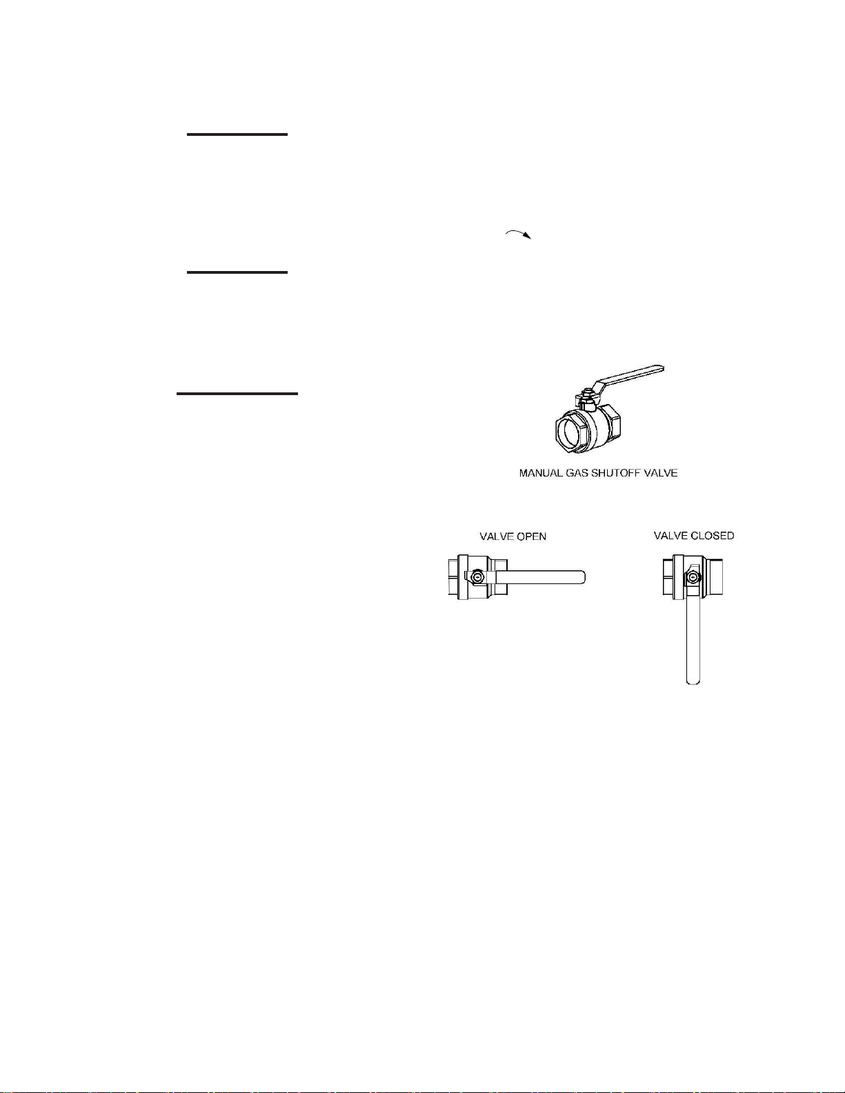
Emergency Shutdown
To shut Down the Unit
Turn the service switch on the Esteem 399
Low NOx control panel to “OFF”
Turn the external manual gas valve handle
clockwise
to “CLOSE”.
If overheating occurs or the gas supply fails
to shut off, close the manual gas shutoff valve
(Figure 1) located external to the unit.
Prolonged Shutdown
After prolonged shutdown, it is recommended
that the startup procedures in Chapter 10 of
this manual be performed, to verify all system
operating parameters. If there is an emergency, turn off the electrical power supply to the
AERCO boiler and close the manual gas valve
located upstream the unit. The installer must
identify the emergency shut-off device.
Figure 1: Typical Manual Gas Shutoff Valve
2
GF-125
Page 9
IF YOU SMELL GAS
DANGER!
IF YOU SMELL GAS
• Do Not try to light any appliance
• Do Not touch any electrical switch
• Do Not use any phone or cell phone in your building.
• Immediately call your gas supplier from a different location.
• Follow the gas supplier’s instructions.
• If you cannot reach your gas supplier, call the fi re department.
IMPORTANT
Installation and service must be performed by a qualifi ed installer, service
agency or the gas supplier.
DANGER!
DO NOT USE THIS APPLIANCE IF ANY PART
HAS BEEN UNDER WATER. IMMEDIATELY CALL
A QUALIFIED SERVICE TECHNICIAN TO INSPECT
THE APPLIANCE AND TO REPLACE ANY PART OF
THE CONTROL SYSTEM WHICH HAS BEEN UNDER
WATER.
WARNING
SHOULD OVERHEATING OCCUR OR THE GAS
SUPPLY FAILS TO SHUT OFF, TURN OFF THE
MANUAL GAS CONTROL VALVE EXTERNAL TO
THE APPLIANCE.
WARNING
DO NOT ADD COLD MAKE UP WATER WHEN THE
BOILER IS HOT. THERMAL SHOCK CAN CAUSE
POTENTIAL CRACKS IN THE HEAT EXCHANGER.
CAUTION
Avoid electrical shock by disconnecting
the electrical supply prior to performing
maintenance when servicing the boiler:
WARNING
PRIOR TO INSTALLING THIS PRODUCT READ ALL
INSTRUCTIONS INCLUDED IN THIS MANUAL AND
ALL ACCOMPANYING MANUALS/DOCUMENTS.
ERFORM ALL INSTALLATION STEPS REQUIRED
P
IN THESE MANUALS IN THE PROPER ORDER GIV-
EN. FAILURE TO ADHERE TO THE GUIDELINES
WITHIN THESE MANUALS CAN RESULT IN SEVERE
PERSONAL INJURY, DEATH OR SUBSTANTIAL
PROPERTY DAMAGE.
Please have the unit’s model number and the
serial number from the rating label, on the
backside of the control panel when inquiring
about service or troubleshooting.
AERCO International accepts no liability for
any damage resulting from incorrect installation or from the use of components or fi ttings
not specifi ed by AERCO International.
GF-125
3
Page 10

Chapter 2 Pre-Installation Items
Code Compliance
This product must be installed in accordance
to the following:
• All applicable local, state, national and
provincial codes, ordinances, regulations
and laws.
• For installations in Massachusetts, code
requires the boiler to be installed by a
licensed plumber or gas fi tter, and if anti-
freeze is utilized, the installation of a reduced pressure backfl ow preventer device
is required in the boiler’s cold water fi ll or
make up water supply line.
• For installation in Massachusetts all direct
vented appliances must comply with the
guidelines as outlined on page 13.
• The National Fuel Gas Code NFPA54/
ANSI Z 223.1 - Latest edition.
• National Electric Code ANSI/NFPA 70.
• For installations in Canada -“Installation
Code for Gas Burning Equipment” CGA/
B149.1 or B149.2 Canadian Electrical
Code Part 1 CSA C22.1.
Standards for Controls and Safety Devices for
Automatically Fired Boilers, ANSI/ASME CSD1, when required.
Determining Product Location
Before locating the Esteem 399 Low NOx
check for convenient locations to:
• Heating system piping
• Venting
• Gas supply piping
• Electrical service
Ensure the boiler location allows the combustion air/vent piping to be routed directly
through the building and terminate properly
outside with a minimum amount of length and
bends.
Ensure the area chosen for the installation of
the Esteem 399 Low NOx is free of any combustible materials, gasoline and other flammable liquids.
WARNING
FAILURE TO REMOVE OR MAINTAIN THE AREA
FREE OF COMBUSTIBLE MATERIALS, GASOLINE
AND OTHER FLAMMABLE LIQUIDS OR VAPORS
CAN RESULT IN SEVERE PERSONAL INJURY,
DEATH OR SUBSTANTIAL PROPERTY DAMAGE.
NOTICE
The Esteem 399 Low NOx boiler gas
manifold and gas controls meet the
safe lighting and other performance requirements as specifi ed in ANSI Z21.13
latest edition.
4
Ensure the Esteem 399 Low NOx and its controls are protected from dripping or spraying
water during normal operation or service.
The Esteem 399 Low NOx should be installed
in a location so that any water leaking from the
boiler or piping connections or relief valve will
not cause damage to the area surrounding the
unit or any lower floors in the structure.
GF-125
Page 11

Boiler Replacement
If the Esteem 399 Low NOx is replacing an
existing boiler, the following items should be
checked and corrected prior to installation:
• Boiler piping leaks and corrosion.
• Improper location and sizing of the
expansion tank on the boiler heating
loop.
• If applicable, level and quality of freeze
protection within the boiler system.
See Warning on ”Handling Previously Fired
Combustion Chamber Insulation” on page 67
Recommended Clearances
Boiler Replacement
The Esteem 399 Low NOx is approved for
zero clearance to combustibles, excluding
vent and boiler piping.
• Boiler Piping - 1/4 inch from combustible
materials.
• See Concentric Vent System Installation
Supplement GF-125V for vent clearance
requirements.
To provide service access to the unit it is recommended that the following clearances be
maintained:
Top jacket 24 inches [610 mm].
Front 24 inches [610 mm].
Rear 0 inches
Sides 6 inches [153 mm]
Bottom piping 24 inches [610 mm].
WARNING
IF THE CLEARANCES LISTED ABOVE CANNOT BE
MAINTAINED OR THE ENCLOSURE IN WHICH THE
BOILER IS INSTALLED IS LESS THAN 85 CUBIC
FEET, THE SPACE MUST BE VENTILATED. SEEP-
AGE 8 FOR REQUIREMENTS.
GF-125
5
Page 12

NOTICE
CAUTION
When maintaining zero clearance or
less than recommended clearances,
some product labeling may become
hidden and unreadable.
WARNING
WHEN INSTALLING THE ESTEEM 399 LOW NOX
IN A CONFINED SPACE, SUFFICIENT AIR MUST
BE PROVIDED FOR PROPER COMBUSTION AND
VENTING AND TO ALLOW, UNDER NORMAL OPER-
ATING CONDITIONS, PROPER AIR FLOW AROUND
THE PRODUCT TO MAINTAIN AMBIENT TEMPERA-
TURES WITHIN SAFE LIMITS TO COMPLY WITH
THE NATIONAL FUEL GAS CODE NFPA 54 -
LATEST EDITION.
Residential Garage Installations
When installing the Esteem 399 Low NOx
in a residential garage, the following special
precautions per NFPA 54/ANSI Z223.1 must
be taken:
The boiler freeze protection feature is
disabled during a hard lockout, however the space heating circulator will
operate.
CAUTION
The boiler freeze protection feature
is designed to protect the boiler. The
boiler should be installed in a primary/
secondary piping arrangement if it is
installed in an unheated space or exposed to water temperatures of 46ºF or
less. See “Chapter 5 Boiler Piping” on
page 16 for primary/secondary piping examples. See Chapter 10 for antifreeze
guides.
• Mount the unit a minimum 18 inches
[458 mm] above the floor level of the
garage. Ensure the burner and ignition
devices / controls are no less than 18
inches [458 mm] above the floor level.
• Locate or protect the unit in a manner
so it cannot be damaged by a moving
vehicle.
Boiler Freeze Protection Feature
The boiler control has a freeze protection feature built in. This feature monitors the boiler
temperature and responds as follows when no
call for heat is present:
• 46ºF Boiler circulator is ON
• 38ºF Boiler circulator is ON and burner
operates at low fire
• 50ºF Burner OFF and boiler circulator
operates for approximately 10 minutes
66
GF-125 GF-125
Page 13

Chapter 3 Combustion Air and Venting
Combustion Air Contamination
WARNING
IF THE ESTEEM 399 LOW NOX COMBUSTION
AIR INLET IS LOCATED IN ANY AREA LIKELY TO
CAUSE OR CONTAIN CONTAMINATION, OR IF
PRODUCTS, WHICH WOULD CONTAMINATE THE
AIR CANNOT BE REMOVED, THE COMBUSTION
AIR MUST BE RE-PIPED AND TERMINATED TO
ANOTHER LOCATION. CONTAMINATED COMBUS-
TION AIR WILL DAMAGE THE UNIT AND ITS BURN-
ER SYSTEM, RESULTING IN POSSIBLE SEVERE
PERSONAL INJURY, DEATH OR SUBSTANTIAL
PROPERTY DAMAGE.
WARNING
DO NOT OPERATE AN ESTEEM 399 LOW NOX
IF ITS COMBUSTION AIR INLET IS LOCATED NEAR
A LAUNDRY ROOM OR POOL FACILITY. THESE
AREAS WILL ALWAYS CONTAIN HAZARDOUS
CONTAMINANTS.
Pool and laundry products and common household and hobby products often contain fluorine
or chlorine compounds. When these chemicals pass through the burner and vent system,
they can form strong acids. These acids can
create corrosion of the heat exchanger, burner
components and vent system, causing serious
damage and presenting a possible threat of
flue gas spillage or water leakage into the surrounding area.
Please read the information listed below. If
contaminating chemicals are located near the
area of the combustion air inlet, the installer
should pipe the combustion air inlet to an outside area free of these chemicals per Chapter
5 of this installation manual.
Potential contaminating products
• Spray cans containing chloro/fl uorocar-
bons
• Permanent Wave Solutions
• Chlorinated wax
• Chlorine - based swimming pool chemicals
/ cleaners
• Calcium Chloride for melting ice
• Sodium Chloride for water softening
• Refrigerant leaks
• Paint or varnish removers
• Hydrochloric acid / muriatic acid
• Cements and glues
• Antistatic fabric softeners used in clothes
dryers
• Chlorine-type bleaches, detergents, and
cleaning solvents
• Adhesives and other similar products
Areas likely to have contaminants
• Dry cleaning / laundry areas and establishments
• Beauty salons
• Metal fabrication shops
• Swimming pools and health spas
• Refrigeration Repair shops
• Photo processing plants
• Auto body shops
• Plastic manufacturing plants
• Furniture refi nishing areas and establish-
ments
• New building construction
• Remodeling areas
• Garages with workshops
The above lists are NOT comprehensive.
Installer, The end user and service personnel
are responsible for certifying the safety of any
and all materials that may affect the quality of
the combustion air.
GF-125
7
Page 14

Ventilation and Combustion Air Requirements - Direct Vent
Ventilation and Combustion Air
Requirements - Direct Vent
A Direct Vent appliance uses uncontaminated
outdoor air (piped directly to the appliance) for
combustion.
For Direct Vent installations, involving only the
Esteem 399 Low NOx , in which the minimum
service clearances are maintained as listed on
page 5, no ventilation openings are required.
For Direct Vent, zero clearance installations
involving only the Esteem 399 Low NOx , the
space / enclosure must have two openings
for ventilation. The openings must be sized to
provide 1 square inch of free area per 1,000
BTUH of boiler input. The openings must be
placed 12 inches from the top of the space and
12 inches from the floor of the space.
For installations where the Esteem 399 Low
NOx shares the space with air movers (exhaust
fan, clothes dryers, fireplaces, etc.) and other
combustion equipment (gas or oil) the space
must be provided with adequate air openings
to provide ventilation and combustion air to
all the equipment. Sizing of the ventilation /
combustion air openings must comply with
the National Fuel Gas Code NFPA 54, ANSI
Z223.1 for installations in the U.S. or CSA
B149.1 and B149.2 for installations in Canada.
INGS IS NOT REQUIRED. FAILURE TO PROVIDE
PROPERLY SIZED OPENINGS COULD RESULT IN
SEVERE PERSONAL INJURY, DEATH OR PROP-
ERTY DAMAGE.
Ventilation and Combustion Air
Requirements - Category IV
A Category IV appliance uses uncontaminated
indoor or outdoor air (surrounding the appliance) for combustion.
Piping uncontaminated combustion air directly
from the outdoors to the appliance is recommended. This reduces the risks associated with
indoor contaminates, flammable vapors and
tight housing construction. This practice also
promotes higher system efficiency.
For installations in which the Esteem 399 Low
NOx shares the space with air movers (exhaust
fan, clothes dryers, fireplaces, etc.) and other
combustion equipment (gas or oil) the space
must be provided with adequate air openings
to provide ventilation and combustion air to
all the equipment. Sizing of the ventilation /
combustion air openings must comply with
the National Fuel Gas Code NFPA 54, ANSI
Z223.1 for installations in the U.S. or CSA
B149.1 and B149.2 for installations in Canada,
as referenced in this chapter of the manual and
titled Methods of Supplying Combustion Air to
a Space.
WARNING
THE SPACE MUST BE PROVIDED WITH VENTILA-
TION / COMBUSTION AIR OPENINGS PROPERLY
SIZED FOR ALL MAKE-UP AIR REQUIREMENTS
EXHAUST FANS, CLOTHES DRYERS, ETC.) AND
(
THE TOTAL INPUT OF ALL APPLIANCES LOCATED
IN THE SAME SPACE AS THE ESTEEM 399 LOW
X , EXCLUDING THE INPUT OF A DIRECT
NO
ENT ESTEEM 399 LOW NOX WHICH USES
V
COMBUSTION AIR DIRECTLY FROM THE OUTSIDE,
THUS ADDITIONAL FREE AREA FOR THE OPEN-
8
WARNING
THE SPACE MUST BE PROVIDED WITH VENTILA-
TION / COMBUSTION AIR OPENINGS PROPERLY
SIZED FOR ALL MAKE-UP AIR REQUIREMENTS
EXHAUST FANS, CLOTHES DRYERS, ETC.) AND
(
THE TOTAL INPUT OF ALL APPLIANCES, INCLUD-
ING THE ESTEEM 399 LOW NOX WHEN LOCAT-
ED IN THE SAME SPACE. FAILURE TO PROVIDE
PROPERLY SIZED OPENINGS COULD RESULT IN
SEVERE PERSONAL INJURY, DEATH OR PROP-
ERTY DAMAGE.
GF-125
Page 15
Ventilation and Combustion Air Requirements - Category IV
Methods of Supplying Combustion Air to
a Confined Space - Category IV
INDOOR COMBUSTION AIR
NOTICE
The methods listed in this section for accessing Indoor Combustion Air assume
that the infi ltration rate is adequate and
not less than .40 ACH. For infi ltration
rates less than .40 ACH, reference the
NFPA 54 National Fuel Gas Code for
additional guidance.
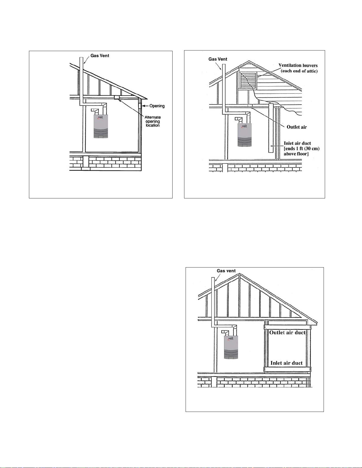
Opening Size and Location
Openings used to connect indoor spaces shall
be sized and located in accordance with the
following see Figure 2
• Combining spaces on the same story.
one opening shall commence within 12
inches of the bottom of the enclosure.
The minimum dimension of air openings
shall be not less than 3 inches.
• Combining spaces in different stories.
The volumes of spaces in different stories shall be considered as communicating spaces where such spaces are
connected by one or more openings in
doors or floors having a total minimum
free area of 2 sq. in./1000 Btu/hr of total
input rating of all gas utilization equipment.
OUTDOOR COMBUSTION AIR
Isolating the combustion appliance room from
the rest of the building and bringing in uncontaminated outside air for combustion and ventilation is always preferred.
Opening Size and Location
Figure 2: :
All Combustion Air from Adjacent Indoor Spaces
Through Indoor Combustion Openings
Each opening shall have a minimum free
area of 1 sq. in./1000 Btu/hr of the total
input rating of all gas utilization equipment in the space, but not less than
100 sq. inches. One opening shall commence within 12 inches of the top, and
The minimum dimension of air openings shall
be not less than 3 inches
Openings used to supply combustion and
ventilation air shall be sized and located in
accordance with the following:
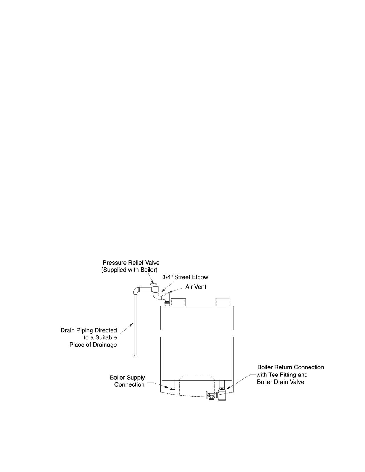
One Permanent Opening Method. See Figure
3
One permanent opening, commencing within
12 inches of the top of the enclosure, shall be
provided. The equipment shall have clearances
of at least 1 inch from the sides and 6 inches
from the front of the appliance. The opening
shall directly communicate with the outdoors or
shall communicate through a vertical or horizontal duct to the outdoors or spaces that freely
communicate with the outdoors and shall have
a minimum free area of the following:
GF-125
9
Page 16
Ventilation and Combustion Air Requirements - Category IV
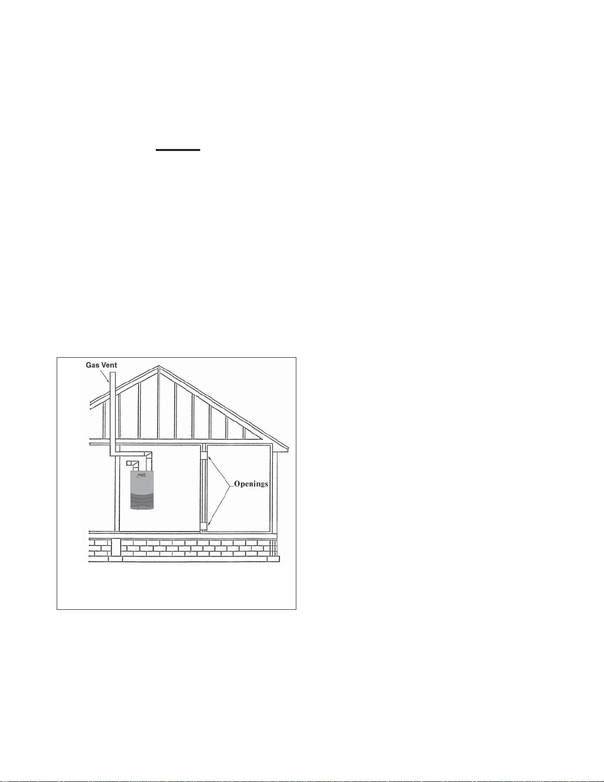
Figure 3: :
All Combustion Air from Outdoors Through One
Permanent Air Opening
• 1 sq. in./3000 Btu/hr of the total input
rating of all equipment located in the
enclosures, and
• Not less than the sum of the areas of all
vent connectors in the space.
Two Permanent Openings Method.
Two permanent openings, one commencing
within 12 inches of the top and one commencing within 12 inches of the bottom of the enclosure, shall be provided. The openings shall
communicate directly, or by ducts, with the
outdoors or spaces that freely communicate
with the outdoors, as follows:
• Where directly communicating with the
outdoors or where communication to the
outdoors is through vertical ducts, each
opening shall have a minimum free area of
1 sq. in./4000 Btu/hr of total input rating for
all equipment in the enclosure.
See Figure 4.
Figure 4: :
All Combustion Air from Outdoors Through
Ventilated Attic
• Where communicating with the outdoors
is through horizontal ducts, each opening
shall have a minimum free area of not less
than 1 sq. in./2000 Btu/hr of total input rating of all equipment in the enclosure. See
Figure 5.
Figure 5: :
All Combustion Air from Outdoors through
Horizontal Ducts
10
GF-125
Page 17

Combustion Air and Vent Piping
COMBINATION OF INDOOR AND OUTDOOR
OMBUSTION AIR
C
Indoor Openings: Where used, openings connecting the interior spaces shall comply with
the Indoor Combustion Air section on page 9.
Outdoor Opening(s) Location. Outdoor
opening(s) shall be located in accordance with
the Outdoor Combustion Air section.
Outdoor Opening(s) Size. Outdoor opening(s) shall
be calculated in accordance with the following:
• The ratio of the interior spaces shall be
the available volume of all communicating
spaces divided by the required volume.
• The outdoor size reduction factor shall be
1 minus the ratio of interior spaces.
• The minimum size of outdoor opening(s)
calculated in accordance with the above
outdoor air section multiplied by the reduction factor. The minimum dimension of air
openings shall not be less than 3 in.
The Esteem 399 Low NOx is certified per
ANSI Z21.13 as a Category IV or Direct Vent
(sealed combustion) appliance. A Category
IV appliance utilizes uncontaminated indoor
or outdoor air (surrounding the appliance) for
combustion. A Direct Vent appliance utilizes
uncontaminated outdoor air (piped directly to
the appliance) for combustion.
Piping uncontaminated combustion air directly
from the outdoors to the appliance is recommended. This reduces the risks associated with
indoor contaminates, flammable vapors and
tight housing construction. This practice also
promotes higher system efficiency.
NOTICE
Install combustion air and vent pipe as
detailed in the Esteem 399 Low NOx
Vent Supplement included in the boiler
installation envelope. Refer to optional
vent kit instructions for addition vent installation instructions.
DANGER!
DO NOT INSTALL THE ESTEEM 399 LOW NOX
INTO A COMMON VENT WITH OTHER GAS OR OIL
APPLIANCES. THIS MAY CAUSE FLUE GAS SPILL-
AGE OR APPLIANCE MALFUNCTION, RESULTING
IN POSSIBLE SEVERE PERSONAL INJURY, DEATH
OR SUBSTANTIAL PROPERTY DAMAGE.
Combustion Air and Vent Piping
DANGER!
COMBUSTION AIR AND VENT PIPING MUST BE
SEALED GAS TIGHT AND MEET ALL PROVIDED IN-
STRUCTIONS AND APPLICABLE CODES, FAILURE
TO COMPLY WILL RESULT IN SEVERE PERSONAL
INJURY OR DEATH.
The Esteem 399 Low NOx requires a Category
IV venting system, which is designed for pressurized venting and condensate.
Removal of an Existing Boiler from a
Common Vent System
DANGER!
DO NOT INSTALL THE ESTEEM 399 LOW NOX
INTO A COMMON VENT WITH OTHER GAS OR OIL
APPLIANCES. THIS MAY CAUSE FLUE GAS SPILL-
AGE OR APPLIANCE MALFUNCTION, RESULTING
IN POSSIBLE SEVERE PERSONAL INJURY, DEATH
OR SUBSTANTIAL PROPERTY DAMAGE.
NOTICE
When an existing boiler is removed
from a common venting system, the
common venting system is likely to be
too large for proper venting of the remaining appliances.
At the time of removal of an existing boiler,
the following steps shall be followed with each
appliance remaining connected to the com-
GF-125
11
Page 18

Removal of an Existing Boiler from a Common Vent System
mon venting system placed in operation, while
the other appliances remaining connected to
the common venting system are not in operation.
• Seal any unused openings in the common
venting system.
• Visually inspect the venting system for
proper size and horizontal pitch and determine there is no blockage or restriction,
leakage, corrosion and other defi ciencies
which could cause an unsafe condition.
• Insofar as is practical, close all building
doors and windows and all doors between
the space in which the appliances remaining connected to the common venting
system are located and other spaces of
the building. Turn on clothes dryers and
any appliance not connected to the common venting system. Turn on any exhaust
fans, such as range hoods and bathroom
exhausts, so they will operate at maximum
speed. Do not operate a summer exhaust
fan. Close fi replace dampers.
• Operate the appliance being inspected. Follow the lighting instructions. Adjust
thermostat so appliance will operate continuously.
• Test for spillage at the draft hood relief
opening after 5 minutes of main burner operation. Use the fl ame of a match or candle,
or smoke from a cigarette, cigar or pipe.
• After it has been determined that each appliance remaining connected to the common venting system properly vents when
tested as outlined above, return doors,
windows, exhaust fans, fi replace dampers,
and any other gas-burning appliance to
their previous condition of use.
• Any improper operation of the common
venting system should be corrected so the
installation conforms with the National Fuel
Gas Code, ANSI Z223.1/NFPA 54 and/or
CAN/CGA B149, Installation codes. When
re-sizing any portion of the common venting system, the common venting system
should be re-sized to approach the appropriate tables in Part II of the National Fuel
Gas Code ANSI Z223.1/NFPA 54 and/or
CAN/CGA B149, Installation codes.
12
GF-125
Page 19

Commonwealth of Massachusetts Installations Only
For direct-vent appliances, mechanical-vent
heating appliances or domestic hot water
equipment, where the bottom of the vent terminal and the air intake is installed below four
feet above grade the following requirements
must be satisfied:
• 1. If there is not one already present,
on each floor level where there are
bedroom(s), a carbon monoxide detector and alarm shall be placed in the living area outside the bedroom(s). The
carbon monoxide detector shall comply
with NFPA 720 (2005 Edition).
• 2. A carbon monoxide detector shall
also be located in the room that houses
the appliance or equipment and shall:
• a. Be powered by the same
electrical circuit as the appliance
or equipment such that only one
service switch services both the
appliance and the carbon monoxide
detector;
• b. Have battery back-up power;
• c. Meet ANSI/UL 2034
Standards and comply with NFPA
720 (2005 Edition); and
• d. Have been approved and
listed by the Nationally Recognized
Testing Laboratory as recognized
under 527 CMR.
• 3. A Product-approved vent terminal
must be used, and if applicable, a
Product-approved air intake must be
used. Installation shall be in strict compliance with the manufacturer’s instructions. A copy of the installation instructions shall remain with the appliance
or equipment at the completion of the
installation.
location of vent terminal. The plate shall
be of sufficient size to be easily read
from a distance of eight feet away, and
read “Gas Vent Directly Below”.
NOTICE
Installer must provide tag identifi cation
plate and ensure the lettering meets
code requirements.
For direct-vent appliances, mechanical-vent
heating appliances or domestic hot water
equipment, where the bottom of the vent terminal and the air intake are installed above four
feet above grade the following requirements
must be satisfied:
• 1. If there is not one already present,
on each floor level where there are
bedroom(s), a carbon monoxide detector and alarm shall be placed in the living area outside the bedroom(s). The
carbon monoxide detector shall comply
with NFPA 720 (2005 Edition).
• 2. A carbon monoxide detector shall:
• a. Be located in the room that
houses the appliances or equipment;
• b. Be either hard wired or battery powered or both; and
• c. Shall comply with NFPA 720
(2005 Edition)
• 3. A Product-approved vent terminal
must be used, and if applicable, a
Product-approved air intake must be
used. Installation shall be in strict compliance with the manufacturer’s instructions. A copy of the installation instructions shall remain with the appliance
or equipment at the completion of the
installation.
• 4. A metal or plastic identification plate
shall be mounted at the exterior of the
building, four feet directly above the
GF-125
13
Page 20

Chapter 4 Unit Preparations
Handling Instructions
The Esteem 399 Low NOx is generally easier
to handle and maneuver once removed from
the shipping carton.
To remove the shipping carton:
CAUTION
Use care not to lift the unit from, or
place the unit on the front plastic control panel, damage can occur. Use care
not to drop, bump or rotate the boiler
upside down, as damage to the boiler
will result.
1. Remove any shipping straps and open
the side of the shipping carton.
2. Slide the unit with the foam inserts out of
the carton.
3. Discard all packing materials.
Wall Mounting Installation
The Esteem 399 Low NOx should be wall
mounted using the bracket provided with
the boiler. The Esteem 399 Low NOx is not
designed for floor installation. If floor installation is required an optional floor stand is available through AERCO International.
WARNING
THE WALL USED FOR MOUNTING THE ESTEEM
399 L
AND CAPABLE OF SUPPORTING A MINIMUM 250
POUNDS [115 KG] FOR ESTEEM 399 LOW NOX
. F
MENTS COULD RESULT IN PERSONAL INJURY,
DEATH OR SUBSTANTIAL PROPERTY DAMAGE.
Wall Mounting Guidelines
• The boiler is heavy and bulky. A minimum
• DO NOT mount or attempt to mount the
OW NOX MUST BE VERTICALLY PLUMBED
AILURE TO COMPLY WITH THESE REQUIRE-
of 2 people is required for mounting the
boiler.
wall bracket to hollow sheet rock or lath
walls using anchors. Only install boiler to
studs or equivalent wood structure.
• The wall-mounting bracket is designed
for stud spacing of 12 inch or 16 inch on
centers. For unconventional stud spacing,
a solid / secure mounting surface must be
provided for installation of the bracket.
• For mounting on wood studs, install the
bracket using the lag screws provided with
the boiler. Ensure both lag screws are
installed securely in the studs.
• For mounting on metal studs, install the
bracket to the studs using 3/16” toggle
bolts and washers.
• For mounting on solid walls (rock, concrete,
brick, cinder block, etc.), install the wall
bracket using anchors (double expansion
shields) and bolts with washers provided
with the boiler.
WARNING
USE EXTREME CARE NOT TO DROP THE BOILER
OR CAUSE BODILY INJURY WHILE LIFTING OR
MOUNTING THE BOILER ONTO THE BRACKET.
NCE MOUNTED VERIFY THAT THE BOILER IS
O
SECURELY ATTACHED TO THE BRACKET AND
WALL. FAILURE TO COMPLY WITH THE ABOVE
GUIDELINES COULD RESULT IN PROPERTY DAM-
AGE, PERSONAL INJURY OR DEATH.
Stud Wall Installation
• To distribute the weight of the boiler evenly
when mounting onto a stud wall it is recommended to use the Esteem 399 Low
NOx Wall Frame kit.
• When using the wall frame to mount the
boiler reference the kit installation instructions and ensure the frame is securely
fastened to the wall.
• If the structure of wall is questionable,
in supporting a minimum weight of 250
pounds [115 kg.], it is recommended to use
the optional fl oor stand.
Wall Bracket Installation - Solid Walls
14
GF-125
Page 21

Boiler Mounting
• Locate the general area of the boiler placement.
• Place the wall-mounting bracket on the
wall ensuring the upper edge of the bracket is away from the wall.
• Level the bracket and use a pencil to mark
the location of the mounting slots on the
wall.
• Remove the bracket from the wall and drill
a 5/8” diameter hole by 1-3/8” deep positioned in the center of each mark.
• Install the anchors (provided) fl ush or
slightly recessed in the drilled holes with
threaded side facing down.
• Reposition the bracket on the wall and
align mounting slots/holes. Insert the two
bolts (provided) through the mounting
slots/holes and loosely tighten.
• Level bracket and tighten bolts securely.
Boiler Mounting
• Obtain assistance in lifting the boiler onto
the wall bracket.
• Install the boiler making sure the boiler
mounting lip located along the upper edge
of the rear jacket panel engages the wallmounting bracket. Ensure the boiler is
seated properly and is secure.
GF-125
15
Page 22

Chapter 5 Boiler Piping
General Piping Requirements
• All plumbing must meet or exceed all local,
state and national plumbing codes.
• Support all piping using hangers. DO NOT
support piping by the unit or its components.
• Use isolation valves to isolate system components.
• Install unions for easy removal of the
Esteem 399 Low NOx from the system
piping.
WARNING!
USE A TWO WRENCH METHOD WHEN TIGHTEN-
ING PIPING ONTO THE BOILER CONNECTIONS.
SE ONE WRENCH TO PREVENT THE BOILER
U
PIPING FROM TURNING / TWISTING. FAILURE
TO SUPPORT THE BOILER PIPING AND CONNEC-
TIONS IN THIS MANNER COULD CAUSE DAMAGE
TO THE BOILER AND ITS COMPONENTS.
Pressure Relief Valve
• Length should be as short and direct as
possible. The size of the discharge line
should not be reduced, maintain the same
size as the outlet of the relief valve.
• Should be directed downward towards the
floor at all times. The piping should terminate at least 6 inches [153 mm] above any
drain connection to allow clear visibility of
the discharge.
• Should terminate with a plain end, not with
a threaded end. The material of the piping
should have a serviceable temperature rating of 250ºF or greater.
• Should not be subject to conditions where
freezing could occur.
• Should not contain any shut-off valves or
obstructions. No shut-off valve should be
piped between the boiler and relief valve.
WARNING!
FAILURE TO COMPLY WITH THE GUIDELINES ON
INSTALLING THE PRESSURE RELIEF VALVE AND
DISCHARGE PIPING CAN RESULT IN PERSONAL
INJURY, DEATH OR SUBSTANTIAL PROPERTY
DAMAGE.
The Esteem 399 Low NOx is supplied with a
30 psi pressure relief valve and must be piped
using the PRV connection as shown in Figure
6, page 17.
To avoid potential water damage to the surrounding area or potential scalding hazard
due to the operation of the relief valve, the
discharge piping:
• Must be connected to the discharge outlet
of the relief valve and directed to a safe
place of disposal.
Low Water Cutoff Device
• The Esteem 399 Low NOx is equipped with
a factory installed pressure switch type Low
Water Cut Off device.
• The minimum operating system pressure
allowable with this device is 10 psig.
• Check local codes if a Low Water Cutoff
Device is required. If so, determine if this
device meets the requirements of the local
codes.
WARNING!
THE ESTEEM 399 LOW NOX CONTROL SYSTEM
SENSES THE SYSTEM WATER TEMPERATURES
ENTERING AND EXITING THE HEAT EXCHANGER
TO PROVIDE PROTECTION AGAINST LOW WATER
CONDITIONS WHERE LOCAL CODES AND JURIS-
DICTION DO NOT ACCEPT A PRESSURE DEVICE
FOR LOW WATER PROTECTION, THEY MAY AC-
CEPT THESE INTEGRAL CONTROL FUNCTIONS AS
A MEANS OF PROVIDING LOW WATER PROTEC-
TION.
16
GF-125
Page 23
Additional Limit Control
Additional Limit Control
If a separate LWCO device is required by
certain local jurisdictions or when the boiler is
installed above the system piping, the following guidelines must be followed:
• The LWCO device must be designed for
water installations, electrode probe-type
is recommended.
• The LWCO device must be installed in a
tee connection on the boiler supply piping above the boiler.
• Wiring of the LWCO device to the
Esteem 399 Low NOx is done directly
onto the 24V terminal strip, see Figure
20, page 34 for available terminals for an
external limit (manual or auto reset).
If the installation is to comply with ASME or
Canadian requirements, an additional high
temperature limit may be needed. Consult
local code requirements to determine compli-
ance. The limit should be installed as follows:
• Install the limit in the boiler supply piping between the boiler and any isolation
valve.
• Maximum set point for the limit is 194ºF.
• For wiring of the limit, see Figure 20,
page 34, using the external limit/manual
reset terminals on the 24V terminal strip.
This will provide a “hard” lockout requiring a manual reset of the control.
Backfl ow Preventer
• Use a backflow preventer valve in the
make-up water supply to the unit as
required by local codes.
Boiler System Piping Applications
All piping applications should use a primary/
secondary piping arrangement as a means to
provide freeze protection of the boiler, which
is an integral function of the boiler control.
Maintain the minimum boiler flow rate, see
Figure 6: Pressure Relief Valve and Boiler Drain Installation
GF-125
17
Page 24

Expansion Tank and Makeup Water
Graph 2 and Graph 3 on page 91 For other
piping arrangements, consult the Engineering
Department at AERCO International.
On piping applications using a single zone or
other recognized piping design arrangements,
it is recommended that the installer uses flow/
check valves with weighted seats at or near
the appliance to prevent gravity circulation.
Expansion Tank and Makeup Water
Ensure the expansion tank is properly sized
for the boiler volume 7 gallons [26 L] for
Esteem 399 Low NOx and the system volume
and temperature.
CAUTION
Undersized expansion tanks will cause
system water to be lost through the
pressure relief valve and cause additional makeup water to be added to the
system. Eventual boiler heat exchanger
failure can result due to this excessive
makeup water addition.
The expansion tank must be located as shown
in Figure 7 and Figure 8 on page 21 when using
a primary/secondary piping arrangement or as
per recognized design methods. Refer to the
expansion tank manufacturer instructions for
additional installation details.
Connect the expansion tank to an air separator only if the air separator is located on the
suction side (inlet) of the system circulator.
Always locate and install the system fill connection at the same location as the expansion
tank connection to the system.
DIAPHRAGM EXPANSION TANK
Always install an automatic air vent on the top
of the air separator to remove residual air from
the system.
CLOSED-TYPE EXPANSION TANK
It is recommended to pitch any horizontal piping upwards toward the expansion tank 1 inch
per 5 feet of piping. Use 3/4” piping for the
expansion tank to allow air within the system
to rise.
CAUTION
DO NOT install automatic air vents on
a closed-type expansion tank system.
Air must remain in the system and be
returned to the expansion tank to provide an air cushion. An automatic air
vent would cause air to be vented from
the system resulting in a water-logged
expansion tank.
Circulator
The Esteem 399 Low NOx must be supplied
with a Central Heating (CH) circulator. The
circulator when wired directly to the Esteem
399 Low NOx will allow for domestic hot water
priority and to provide circulation for the freeze
protection feature of the boiler control. See
Graph 2 and Graph 3 on page 91 for pressure
drop and minimum flow rate through the boiler.
Sizing Primary Piping
See Figure 9 through Figure 15, page 22 and
following, for recommended piping arrangements based on various applications. Size the
piping and system components required in
the space heating system, using recognized
design methods.
18
GF-125
Page 25

Domestic Hot Water System Piping
Domestic Hot Water System Piping
See Figure 9, page 22 for recommended piping
to a DHW system. This recommended piping
configuration ensures priority is given to the
production and recovery of the DHW.
The piping for the DHW is separate from the
boiler system piping and does not require a
primary / secondary piping configuration.
To wire the DHW circulator to the boiler control
module, see Chapter 9 External Wiring.
System Piping - Zone Circulators
Connect the Esteem 399 Low NOx to the system piping as shown in Figure 10 page 23 when
zoning with zone circulators.
The installer must provide a separate circulator for each zone of space heating as well as
the boiler circulator.
System Piping - Through Boiler
In new or retrofit applications in which primary/
secondary arrangement is not used, the Esteem
399 Low NOx allows this flexibility due to a lower
boiler pressure drop, see Graph 2 and Graph 3
on page 91.
Figure 12, page 24 illustrates a multiple zone
valve system with a single system/boiler circulator. A by-pass loop with a pressure differential
valve must be installed on the system piping.
Figure 13, page 24 illustrates a single zone utilizing
the boiler circulator as the system circulator.
System Piping - Radiant Heating
The heat exchanger design of the Esteem
399 Low NOx allows operation in a condensing mode. This feature requires no return
water temperature regulation in radiant heating applications.
NOTICE
To ensure an adequate fl ow rate through
the Esteem 399 Low NOx , the boiler
supply and return piping size must be a
minimum 1-1/2 inch for the Esteem 399
Low NOx .
System Piping - Zone Valves
Connect the Esteem 399 Low NOx to the system
piping as shown in Figure 11, page 23 when zoning with zone valves. The primary / secondary
piping ensures that the boiler loop has sufficient
flow.
NOTICE
To ensure an adequate fl ow rate through
the Esteem 399 Low NOx , the boiler
supply and return piping size must be
a minimum of 1-1/2 inch for the Esteem
399 Low NOx .
Esteem 399 Low NOx can maintained the boiler water supply temperature, eliminating the
need for a mix system to achieve the desired
temperature.
A high temperature limit as shown in Figure
14, page 25 should be installed to ensure that
the primary supply temperature does not
exceed the maximum allowable temperature
for the radiant tubing.
The addition of the high temperature limit is
important if the Esteem 399 Low NOx is connected to a domestic hot water system, which
requires a high primary supply water temperature.
Size the system piping and circulator to provide
the flow needed for the radiant system.
NOTICE
GF-125
The Esteem 399 Low NOx supply and
return piping must be a minimum of
1-1/2 inch .
19
Page 26

System Piping - Special Application
System Piping - Special Application
If the boiler is used in conjunction with a
chilled water/medium system, the boiler and
chiller must be piped in parallel. Install flow/
check valves to prevent the chilled medium
from entering into the boiler.
If the boiler is used to supply hot water to
the heating coils of an air handler where they
may be exposed to chilled air circulation,
install flow/check valves or other automatic
means to prevent gravity circulation of the
boiler water during cooling cycles.
System Piping - Multiple Units
Installation
Use a balanced manifold system as the primary / secondary connection to the space
heating piping as shown in Figure 15 page 26.
Maintain a minimum of 6 inches [153 mm] of
clearance between units to allow for servicing.
Refer to Figure 7 and Figure 8, page 21 to install
air separator and expansion tank.
For the space heating piping refer to the applications mentioned in this manual or use recognized design methods..
20
GF-125
Page 27
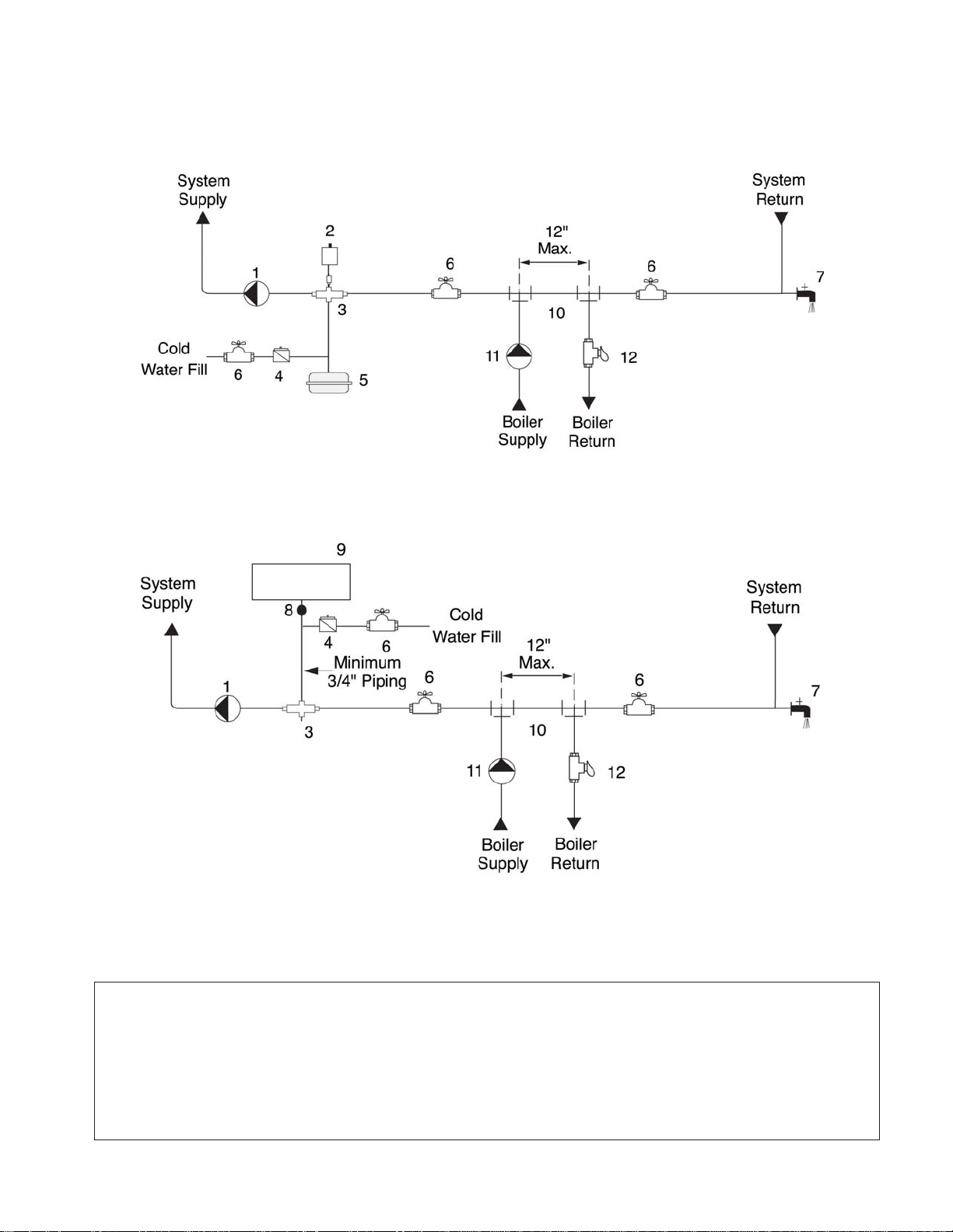
Figure 7: Near Boiler Piping - Diaphragm Expansion Tank
System Piping - Special Application
Figure 8: Near Boiler Piping - Closed Type Expansion Tank
1. System circulator
2. Automatic air vent
3. Air separator
4. Automatic fill valve
5. Diaphragm expansion tank
6. Isolation valve
GF-125
Note: Pitch horizontal
piping upwards (1” of
pitch per 5 ft of piping)
towards expansion tank.
7. Drain/purge valve
8. Tank fitting
9. Closed type expansion tank
10. Primary/secondary connection
11. Boiler circulator
12. Flow/check valve
21
Page 28
System Piping - Special Application
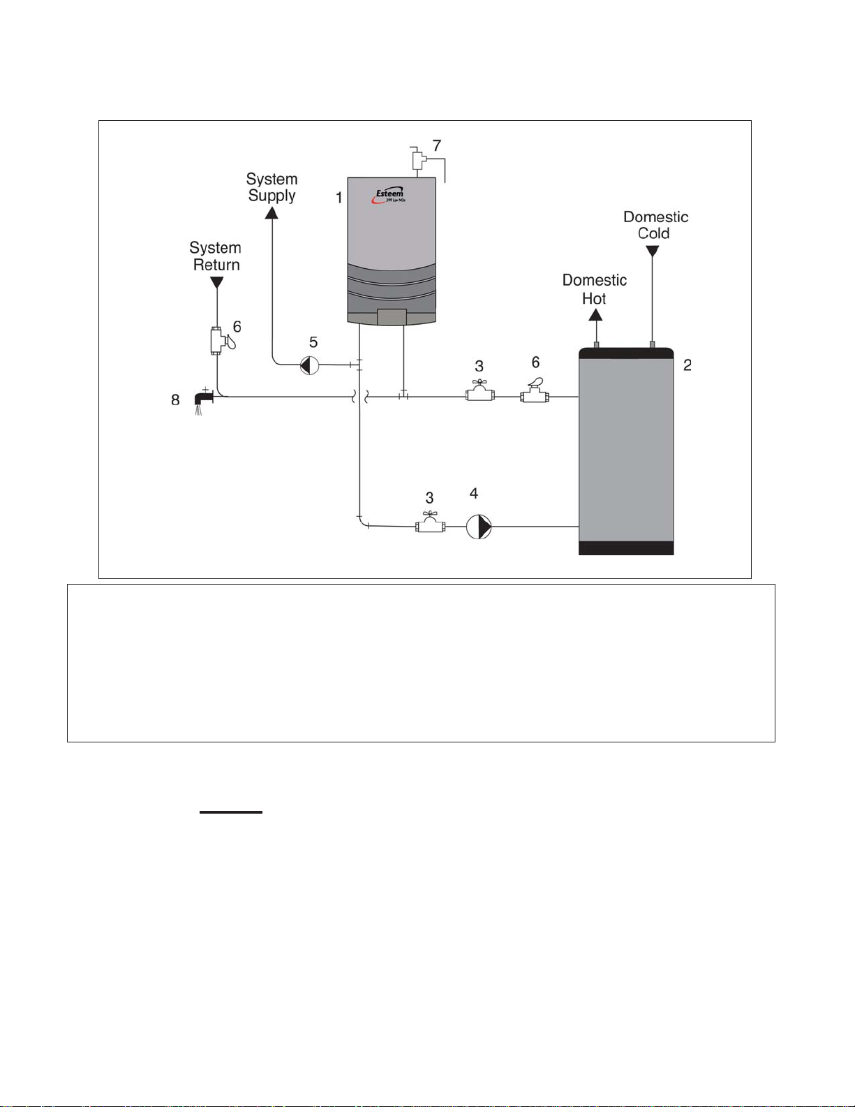
Figure 9: DHW Boiler Piping with an Esteem 399 Low NOx
1. Esteem 399 Low NOx boiler
2. water heater
3. Isolation valve
4. DHW circulator
5. CH circulator
NOTICE
The boiler system piping shown in
Figure 8 must be a “closed” system
to avoid any oxygen contamination
and potential failure of the outer tank
of the water heater.
6. Flow/check valve
7. Pressure relief valve
8. Drain/purge valve
22
GF-125
Page 29
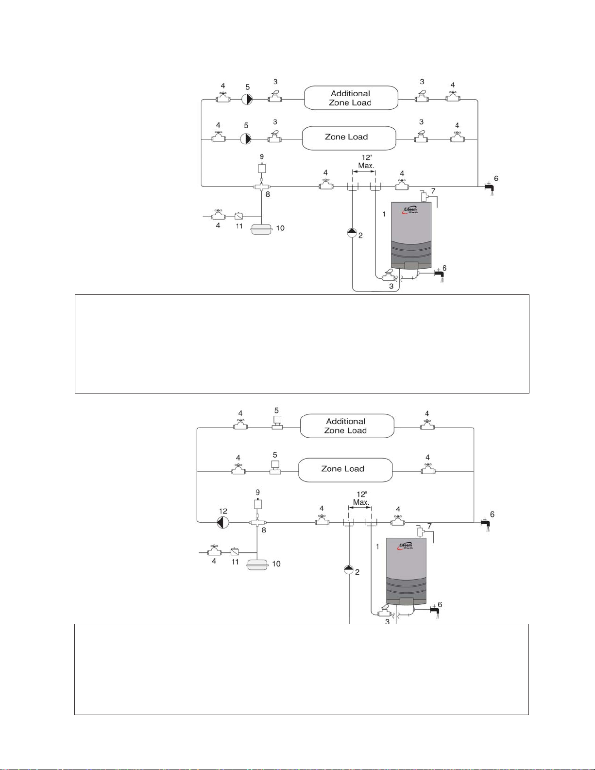
Figure 10: CH System Piping - Zoning with
Zone Circulators
System Piping - Special Application
1. Esteem 399 Low NOx boiler
2. CH circulator
3. Flow/check valve
4 Isolation valve
5. Zone circulator
6. Drain/purge valve
7. Pressure relief valve
8. Air separator
9. Automatic air vent
10. Diaphragm expansion tank
11. Automatic fill valve
Figure 11: CH System Piping - Zoning with Zone
Valves
1. Esteem 399 Low NOx boiler
2. CH circulator
3. Flow/check valve
4 Isolation valve
5. Zone valve
6. Drain/purge valve
GF-125
7. Pressure relief valve
8. Air separator
9. Automatic air vent
10. Diaphragm expansion tank
11. Automatic fill valve
12. System circulator
23
Page 30
System Piping - Special Application
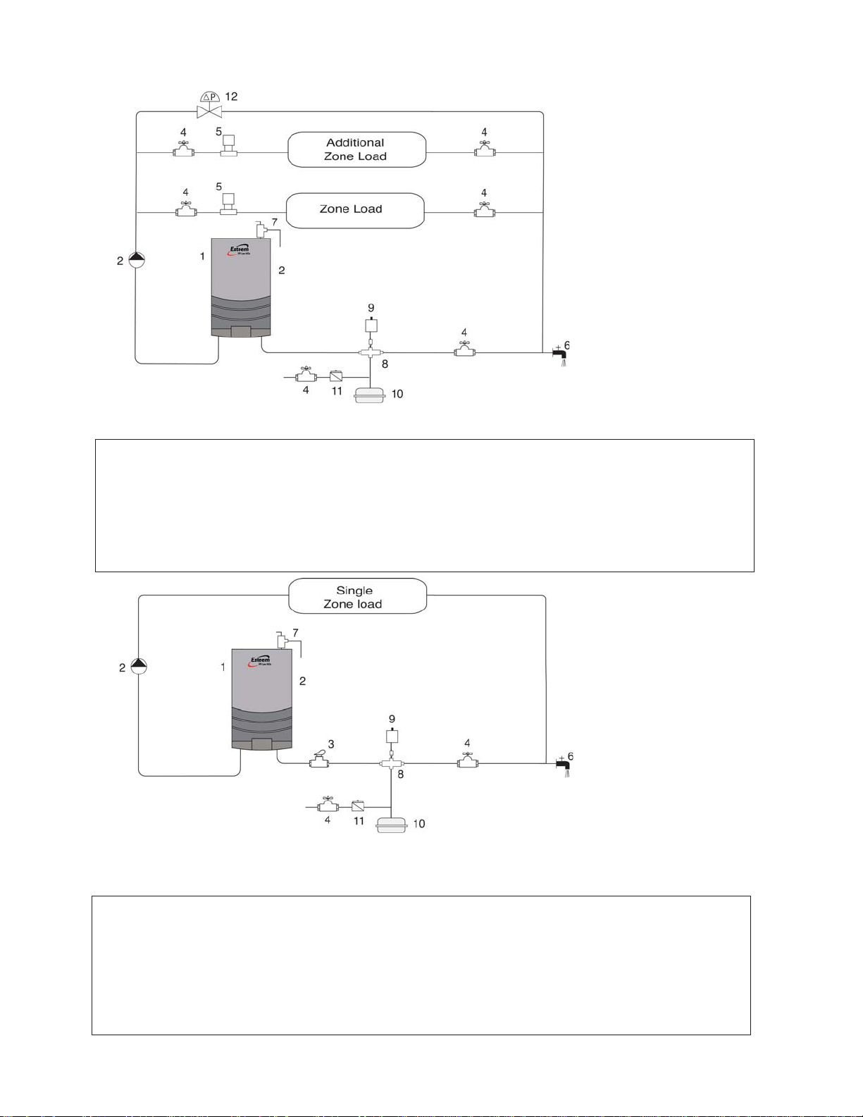
Figure 12: CH System Piping - Multiple Zone Valve with Single System/Boiler Circulator
Note: Verify CH circulator is properly sized
to overcome the system pressure drop and
provide adequate flow
through the boiler system.
1. Esteem 399 Low NOx boiler
2. CH circulator
4. Isolation valve
5. Zone valve
6. Drain/purge valve
7. Pressure relief valve
8. Air separator
9. Automatic air vent
10. Diaphragm expansion tank
11. Automatic fill valve
12. Pressure Differential Valve
Note: Verify CH circulator is properly sized
to overcome the system pressure drop and
provide adequate flow
through the boiler system.
Figure 13: CH System Piping - Single Zone System with Single System/Boiler Circulator
1. Esteem 399 Low NOx boiler
2. CH circulator
3. Flow/check valve
4 Isolation valve
5. Zone valve
6. Drain/purge valve
7. Pressure relief valve
8. Air separator
9. Automatic air vent
10. Diaphragm expansion tank
11. Automatic fill valve
24
GF-125
Page 31

System Piping - Special Application
• Note: Manifold mounted valve
actuators may be used in lieu
of zone valves.
Figure 14: CH System Piping - Radiant/Low Temp. Heating
1. Esteem 399 Low NOx boiler
2. CH circulator
3. Flow check valve
4 Isolation valve
5. Zone valve
6. Drain/purge valve
7. Pressure relief valve
8. Air separator
9. Automatic air vent
10. Diaphragm expansion tank
11. Automatic fill valve
12. System circulator
13. High temperature limit control
GF-125
25
Page 32

1. Boiler circulator
2. Isolation valve
3. Flow/check valve
4. System circulator
5. Drain/purge valve
6. Automatic air vent
7. Air separator
8. Diaphragm expansion
tank
9. Automatic fill valve
Figure 15: Multiple Esteem 399 Low NOx Boiler Piping - Primary / Secondary / Piping using Balanced Manifold System
26
GF-125
Page 33

Chapter 6 Installing Vent, Air Intake & Drain
Installing Vent and Combustion Air
Intake
DANGER!
THE ESTEEM 399 LOW NOX MUST BE VENTED
AND SUPPLIED WITH COMBUSTION AIR AS SHOWN
IN THE ESTEEM 399 LOW NOX VENT SUPPLE-
MENT, INCLUDED IN THE BOILER INSTALLATION
ENVELOPE. REFER TO VENT KIT INSTRUCTIONS
(GF-125V)
TION INSTRUCTIONS. ONCE INSTALLATION IS
COMPLETE, INSPECT THE VENT AND COMBUS-
TION AIR SYSTEM THOROUGHLY TO ENSURE
SYSTEMS ARE AIRTIGHT AND COMPLY WITH THE
INSTRUCTIONS GIVEN IN THE VENTING SUPPLE-
MENT AND ARE WITHIN ALL REQUIREMENTS OF
APPLICABLE CODES. FAILURE TO COMPLY WITH
ALL INSTALLATION REQUIREMENTS CAN CAUSE
SEVERE PERSONAL INJURY OR DEATH.
FOR ADDITIONAL VENT INSTALLA-
Installing Condensate Drain
Assembly
1. Locate the condensate drain assembly
and install as shown in Figure 16, page 28.
NOTICE
The installer may want to fi ll the con-
densate trap with water prior to assembling on the unit.
2. Remove the retaining nut and rubber seal
from the condensate drain assembly and
slide over the heat exchanger condensate
drain nipple. Connect the condensate
drain assembly to the retaining nut and
tighten. Hand tight only!
WARNING!
ENSURE THE CONDENSATE DRAIN ASSEMBLY
CONTAINS THE PLASTIC SEATED BALL. DO NOT
INSTALL THE CONDENSATE DRAIN ASSEMBLY IF
THE BALL IS LOST OR MISSING, REPLACE THE
ENTIRE ASSEMBLY.
4. Using 3/4” x 2’ flexible PVC tube provided, slide the compression nut and rubber
seal over the pipe
NOTICE
The use of 3/4” PVC or CPVC pipe is
also acceptable. If 3/4” pipe is used deburr and chamfer pipe to allow mating
onto the drain assembly.
5. Thread the rubber seal into the compression nut to ease installation of the pipe to
the drain assembly.
6. Seat the pipe onto the drain assembly
and tighten the compression nut. Hand
tight only!
NOTICE
The installer may opt to using 13/16” ID
tubing in lieu of rigid piping.
NOTICE
The drain line materials must be materials approved by the authority having
jurisdiction. In absence of such authority, PVC and CPVC piping must comply with ASTM D1785 or D2845. The
cement and primer used on the piping must comply with ASME D2564 or
F493. For installations in Canada, use
CSA or ULC certifi ed PVC or CPVC
pipe, fi ttings and cement/primer.
7. Continue the pipe from the drain assembly to a floor drain or condensate pump.
NOTICE
When selecting and installing a condensate pump, ensure the pump is approved for use with condensing boilers and furnaces. The pump should
be equipped with an overfl ow switch to
prevent property damage from potential
condensate spillage.
3. Remove the compression nut and rubber
seal from the drain outlet.
GF-125
8. The Esteem 399 Low NOx will typically
produce a condensate that is considered
27
Page 34

slightly acidic with a pH content below
3.0. Install a neutralizing filter if required
by authority having jurisdiction.
CAUTION
The condensate drain must remain
fi lled and unobstructed and allow unrestricted fl ow of condensate. The con-
densate should not be subject to conditions where freezing could occur. If the
condensate is subjected to freezing or
becomes obstructed , it can leak, resulting in potential water damage to the
boiler and surrounding area.
28
Figure 16: Condensate Drain Assembly
GF-125
Page 35

Chapter 7 Gas Piping
Gas Supply Piping Connection
NOTICE
The gas supply piping must be installed
in accordance to all local, state and national codes and utility requirements.
1. Install a 1” NPT for the pipe union at the
factory supplied gas nipple, for ease of
service.
2. Install a manual shutoff valve in the gas
supply piping as shown in Figure 17. For
Canadian installations the main shutoff
valve must be tagged and identified by
the installer
3. Install a sediment trap (drip leg) on the
gas supply line prior to connecting to the
Esteem 399 Low NOx gas train as shown
in Figure 17.
4. Support the gas piping using hangers. Do
not support the piping by the unit or its
components.
WARNING
FAILURE TO APPLY PIPE DOPE AS DETAILED
ABOVE CAN RESULT IN SEVERE PERSONAL IN-
JURY, DEATH OR SUBSTANTIAL PROPERTY DAM-
AGE.
WARNING!
USE A TWO-WRENCH METHOD OF TIGHTENING
GAS PIPING NEAR THE UNIT AND ITS GAS PIPING
CONNECTION. USE ONE WRENCH TO PREVENT
THE BOILER GAS LINE CONNECTION FROM TURN-
ING AND THE SECOND TO TIGHTEN ADJACENT
PIPING. FAILURE TO SUPPORT THE BOILER GAS
PIPING CONNECTION COULD DAMAGE THE GAS
LINE COMPONENTS.
5. Purge all air from the gas supply piping.
6. Before placing the boiler into operation,
test all connections for leaks.
• Close the manual shutoff valve during
any pressure test with less than 13”w.c..
• Disconnect the Esteem 399 Low NOx
and its gas valve from the gas supply
piping during any pressure test greater
than 13”w.c..
WARNING!
DO NOT CHECK FOR GAS LEAKS WITH AN OPEN
FLAME. USE A GAS DETECTION DEVICE OR BUB-
BLE TEST. FAILURE TO CHECK FOR GAS LEAKS
CAN CAUSE SEVERE PERSONAL INJURY, DEATH
OR SUBSTANTIAL PROPERTY DAMAGE.
7. Use pipe dope compatible with natural
and propane gases. Apply sparingly only
to the male threads of pipe joints so that
pipe dope does not block gas flow.
Figure 17: Recommended Gas Supply Piping
GF-125
29
Page 36

Natural Gas
Natural Gas
PIPE SIZING - NATURAL GAS
Refer to Table 1 for schedule 40 metallic pipe
length and diameter requirements for natural
gas, based on rated Esteem 399 Low NOx
input (divide by 1,000 to obtain cubic feet per
hour).
• Table 1 is based on Natural Gas with a
specifi c gravity of 0.60 and a pressure
drop through the gas piping of 0.30”w.c..
• - For additional gas piping sizing information, refer to ANSI Z223.1. For Canadian installations refer to B149.1 or B149.2.
NATURAL GAS SUPPLY PRESSURE
REQUIREMENTS
1. Pressure required at the gas valve inlet
supply pressure port:
• Maximum 13”w.c. at flow or no flow conditions to the burner.
2. Install 100% lockup gas pressure regulator
in the gas supply line if inlet pressure can
exceed 13”w.c at any time. Adjust the lockup pressure regulator for 13”w.c maximum.
WARNING!
DO NOT ADJUST OR ATTEMPT TO MEASURE
GAS VALVE OUTLET PRESSURE. THE GAS VALVE
IS FACTORY-SET FOR THE CORRECT OUTLET
PRESSURE. THIS SETTING IS SUITABLE FOR
NATURAL GAS AND PROPANE AND REQUIRES NO
FIELD ADJUSTMENT. ATTEMPTS BY THE INSTALL-
ER TO ADJUST OR MEASURE THE GAS VALVE
OUTLET PRESSURE COULD RESULT IN DAMAGE
TO THE VALVE, CAUSING POTENTIAL SEVERE
PERSONAL INJURY, DEATH OR SUBSTANTIAL
PROPERTY DAMAGE.
NOTICE
The natural gas orifi ce for the Esteem
399 Low NOx is 0.339” (8.6 mm)
• Minimum 5”w.c. during flow conditions
to the burner. Must be verified during
start up and with all other gas appliances operating within the building.
Table 1: Gas Piping Sizing - Natural Gas
Length of Pipe in
Feet
SCH 40 1/2” 3/4” 1” 1-1/4” 1-1/2”
10 132 278 520 1050 1600
20 92 190 350 730 1100
30 73 152 285 590 890
40 63 130 245 500 760
50 56 115 215 440 670
75 45 93 175 360 545
100 38 79 150 305 460
150 31 64 120 250 380
Capacity of Schedule 40 Metallic Pipe in Cubic Feet of Natural Gas Per
Hour (based on 0.60 specific gravity, 0.30” w.c. pressure drop)
30
GF-125
Page 37

Propane Gas
Propane Gas
NOTICE
The propane orifi ce required for the Es-
teem 399 Low NOx is 0.264” (6.7 mm)
WARNING!
DO NOT ADJUST OR ATTEMPT TO MEASURE
GAS VALVE OUTLET PRESSURE. THE GAS VALVE
IS FACTORY-SET. THIS SETTING IS SUITABLE
FOR NATURAL GAS AND PROPANE AND RE-
QUIRES NO FIELD ADJUSTMENT. ATTEMPTS TO
ADJUST OR MEASURE THE GAS VALVE OUTLET
PRESSURE COULD RESULT IN DAMAGE TO THE
VALVE, CAUSING POTENTIAL PROPERTY DAMAGE
PERSONAL INJURY, OR DEATH.
On propane gas applications the incoming gas
regulator should be installed as follows:
• Size the regulator for the appropriate fl ow.
• The regulator diaphragm should be installed horizontally
• Piping before and after the regulator
should be straight rigid pipe for a minimum
of 10 pipe diameters.
• Avoid fl exible pipe between boiler and the
outlet of the regulator.
• If regulator is installed and vented inside, a
vent limiter should be used.
• If regulator is installed or vented outside,
an inverted trap piping arrangement
should be used.
WARNING
PRIOR TO START UP, ENSURE THE UNIT IS SET
TO FIRE PROPANE. CHECK THE RATING LABEL
FOR THE TYPE OF FUEL. CHECK THE GAS VALVE
FOR PROPANE CONVERSION LABEL. IF THERE
IS A CONFLICT OR DOUBT ON THE BURNER SET
UP, REMOVE THE GAS VALVE AND CHECK FOR
THE PROPANE ORIFICE, SEE FIGURE 18, PAGE
AILURE TO ENSURE PROPER BURNER SETUP
31. F
COULD RESULT IN PROPERTY DAMAGE PERSON-
AL INJURY, OR DEATH.
Figure 18: Gas Valve / Venturi Assembly
GF-125
31
Page 38

PIPE SIZING - PROPANE GAS
Contact the local propane gas supplier for recommended sizing of piping, tanks and 100%
lockup gas regulator.
PROPANE GAS SUPPLY PRESSURE
REQUIREMENTS
• Adjust the propane supply regulator provided by the gas supplier for 13”w.c. maximum pressure
• Pressure required at the gas valve inlet
supply pressure port:
• Maximum 13”w.c. at fl ow or no fl ow condi-
tions to the burner
• Minimum 5”w.c. during fl ow conditions to
the burner. Must be verifi ed during start up
and with all other gas appliances operating
within the building.
32
GF-125
Page 39

Chapter 8 Internal Wiring
WARNING
ELECTRICAL SHOCK HAZARD. FOR
YOUR SAFETY, DISCONNECT ELECTRICAL POW-
ER SUPPLY TO THE UNIT BEFORE SERVICING
OR MAKING ANY ELECTRICAL CONNECTIONS
TO AVOID POSSIBLE ELECTRIC SHOCK HAZARD.
AILURE TO DO SO CAN CAUSE SEVERE PER-
F
SONAL INJURY OR DEATH.
CAUTION
Prior to servicing, label all wires before
disconnecting. Wiring errors can cause
improper and dangerous operation.
Verify proper wiring and operation after
servicing.
General Requirements
• Wiring must be NEC Class 1.
• If original wiring as supplied with the unit
must be replaced, use only Type T 90ºC
wire or equivalent as a minimum.
• The Esteem 399 Low NOx must be electrically grounded as required by National
Electrical Code ANSI/NFPA 70 - latest edition and / or the Canadian Electrical Code
Part 1, CSA C22.1, Electrical Code.
Control Module Circulator AMP
Ratings
- AMP draw of the CH circulator not
to exceed 2 amps.
AMP draw of the DHW circulator not to
exceed 2 amps.
Wiring Tool Instructions
1. Locate the wiring tools on the Esteem 399
Low NOx just below the MCBA control in
a plastic bag and below the extra fuses.
2. Locate the terminal blocks on the Esteem
399 Low NOx below the MCBA control.
NOTICE
The 120V Terminals are located on the
left set of Terminal Blocks. The 24V Terminals are located on the right set of
terminal blocks.
3. Carefully pull down on the lower half of
the terminal block to remove.
4. Hook the wiring tool into the desired slot
of the terminal block as shown in Figure
19.
5. Push wiring tool in towards the terminal
block and insert wire in slot at bottom of
terminal block.
6. Repeat steps 4 & 5 until all wiring is complete.
7. Re-connect the lower half of the terminal
block to the upper half.
Figure 19: Using the Wiring Tool on the Terminal
Blocks
GF-125
8. Place the wiring tool back into the plastic
bag or leave tool hooked to a slot on the
24V terminal block.
When wiring the Esteem 399 Low NOx allow
additional length of wire for the access panel to
swing open during servicing.
33
Page 40

Internal Wiring Diagram
Figure 20: Esteem 399 Low NOx Boiler Factory Wiring
See wiring tool instructions, page 33.
To properly connect wires to terminal block, use wiring tool included with Esteem 399 Low NOx .
34
GF-125
Page 41

Chapter 9 External Wiring
Installation Compliance
All field wiring made during installation must
comply with:
• National Electrical Code NFPA 70 and any
other national, state, provincial or local
codes or requirements.
• In Canada, CSA C22.1 Canadian Electrical
Code Part 1, and any other local codes.
WARNING!
ELECTRICAL SHOCK HAZARD. BEFORE
MAKING ANY ELECTRICAL CONNECTIONS TO THE
STEEM 399 LOW NOX , DISCONNECT ELEC-
E
TRICAL POWER SUPPLY AT THE SERVICE PANEL.
AILURE TO COMPLY CAN CAUSE SEVERE PER-
F
SONAL INJURY OR DEATH.
Line Voltage Connections
1. Use shielded cable.
2. Connect a 120 VAC/15A service to the
120V terminal strip on the wiring panel
below the Esteem 399 Low NOx control
module, as shown in Figure 20, page 34.
3. Route the incoming 120 VAC power wire
through the provided openings in the bottom jacket panel.
4. The unit is provided with a service switch
located on the front panel, check local
code requirements for compliance.
NOTICE
If local codes or conditions require an
additional service switch, the installer
must install a fused disconnect for 15
amp (minimum) service switch.
Domestic Hot Water Aquastat Wiring
NOTICE
Use only AERCO International supplied
aquastat (P/N 69107). Other models
can be incompatible with the Esteem
Controller
1. Connect the DHW thermostat (aquastat)
to the 24V terminal strip on the wiring
panel located below the Esteem 399 Low
NOx control module as shown in Figure
20, page 34.
2. Route all wiring through the provided openings, in the bottom jacket
panel. Allow enough wire for access
panel to swing open during servicing.
Thermostat Wiring
1. Connect room thermostat or the end
switch (isolated contact only) of a relay
control panel to the 24V terminal strip on
the wiring panel below the Esteem 399
Low NOx control module, as shown in
Figure 20, page 34.
2. For proper operation install the room
thermostat on an inside wall away from
influences of heat and cold, i.e. water
pipes, areas of draft, lighting fixtures and
fireplaces.
3. Set the thermostat anticipator (if applicable) as follows:
• Set for 0.2 amps when wired directly to
the Esteem 399 Low NOx .
• Set to match the total electrical power
requirements of the connected devices
when wired to zone relays or other
devices. Refer to the relay manufacturers’ specifications and the thermostat
instructions for additional information on
the anticipator setting.
NOTICE
When making low voltage connections
to the Esteem 399 Low NOx, ensure no
external voltage is present in the thermostat circuits. If external voltage is
present, provide an isolated contact to
prevent damage to the control.
GF-125
35
Page 42

CH and DHW Circulator
CH and DHW Circulator
1. Connect the space heating primary circulator to the Esteem 399 Low NOx 120 V
terminals 1,2 and 3 as shown in Figure
20, page 34.
2. Connect the DHW circulator to the
Esteem 399 Low NOx 120 V terminals 4,
5 and 6 as shown in Figure 20, page 34.
Maximum circulator continuous current draw is
2A for each circulator.
System Circulator - Zone Valve
Application
To energize the system circulator shown as
item 12 in Figure 11 page 23 see Figure 21.
Installer to provide a Transformer / Relay
such as Honeywell R8285 or equivalent and
zone valves with isolated end switch such as
Honeywell V8043 or equivalent.
External Modulating Control
The Esteem 399 Low NOx firing rate can be
controlled by an external modulating boiler
controller. See page 34 for wiring and page 58 for
control module setup.
Outdoor Reset Control
The Esteem 399 Low NOx may operate with
a variable boiler operating temperature using
the AERCO International outdoor sensor, see
page 54 for information.
NOTICE
If a fi xed operating temperature is cho-
sen for the boiler system, the outdoor
sensor is not required and should not
be installed.
Additional 24V Limit Wiring
The Esteem 399 Low NOx provides 24V terminal connections for additional limit controls
as shown in Figure 20 page 34. These limit terminal connections will provide a “hard” lockout
requiring a manual reset of the boiler control,
or a “soft” lockout in which the Esteem 399
Low NOx will automatically reset.
Figure 21: Secondary System Circulator Wiring
36
GF-125
Page 43

External Wiring Diagram
4 Wire Zone Valve
External Wiring Diagram
Figure 22: Field Wiring with Zone Circulators
3 Wire Zone Valve
Figure 23: Multiple Zone Field Wiring Using Zone Valves
GF-125
37
Page 44

Figure 24: Field Wiring with Zone Circulators
Figure 25: Typical Zone Relay Panel Wiring
38
GF-125
Page 45

Chapter 10 Start-Up Preparation
Check Boiler System Water
Chemistry
WARNING!
DO NOT USE PETROLEUM-BASE CLEANING OR
SEALING COMPOUNDS IN THE BOILER SYSTEM.
AMAGE TO SEALS AND GASKETS IN THE SYS-
D
TEM COMPONENTS COULD OCCUR, RESULTING
IN SUBSTANTIAL PROPERTY DAMAGE.
NOTICE
System water including additives must
be practically nontoxic, having a toxicity
rating or Class of 1, as listed in Clinical
Toxicology of Commercial Products.
WATER PH LEVEL 6.0 TO 8.0
Maintain the boiler water pH between 6.0 and
8.0. Check using litmus paper or contact a water
treatment company for a chemical analysis.
Flush the systems until the water runs clean
and is free of sediment.
For zoned systems, each zone should be
flushed through a purge valve. Purge valves
and isolation valves should be installed on
each zone to allow proper flushing of the system.
Check and Test Antifreeze
For boiler systems containing antifreeze solutions, follow the antifreeze manufacturer’s
instructions in verifying the inhibitor level and
to ensure the fluid characteristics are within
specifications.
Due to the degradation of inhibitors over time,
antifreeze fluids must be periodically replaced.
Refer to the manufacturer of the antifreeze for
additional instructions.
If the pH does not meet this requirement, do
not operate the Esteem 399 Low NOx or leave
the unit filled until the condition is corrected.
WATER HARDNESS LESS THAN 7 GRAINS
For areas with unusually hard water (hardness above 7 grains) consult a water treatment company.
CHLORINATED WATER
Do not use the Esteem 399 Low NOx to heat
a swimming pool or spa directly.
Maintain the chlorine level of the water at levels considered safe for drinking.
Flush Boiler and Domestic System
to Remove Sediment
The installer must flush the boiler system to
remove any sediment to allow proper operation of the Esteem 399 Low NOx .
NOTICE
System water including additives must
be practically nontoxic, having a toxicity
rating or Class of 1, as listed in Clinical
Toxicology of Commercial Products.
Use of Antifreeze in the Boiler
System
WARNING!
NEVER USE AUTOMOTIVE OR ETHYLENE GLY-
COL ANTIFREEZE OR UNDILUTED ANTIFREEZE IN
THE PRIMARY SYSTEM AS FREEZE PROTECTION.
HIS CAN CAUSE SEVERE PERSONAL INJURY,
T
DEATH OR PROPERTY DAMAGE.
Determine the antifreeze fluid quantity using
the system water content volume and following the antifreeze manufacturer instructions.
The water volume of the Esteem 399 Low NOx
is approximately 7 gallons [26 L] for Esteem 399
Low NOx . Remember to include the volume of
the expansion tank.
GF-125
39
Page 46

Filling the Boiler System
Check with local codes requirements for the
installation of backflow preventers or actual
disconnection from the boiler’s cold water fill
or make up water supply line.
NOTICE
Massachusetts Code requires the installation of a backfl ow preventer if anti-
freeze is used.
Ensure the concentration of antifreeze to
water does not exceed a 50/50 ratio.
NOTICE
System water, including additives, must
be practically nontoxic, having a toxicity
rating or Class of 1, as listed in Clinical
Toxicology of Commercial Products.
Filling the Boiler System
1. Close the boiler drain valve located on
the bottom of the unit and any manual or
automatic air vent in the system.
2. Open all system isolation valves.
3. Fill the boiler system to correct system
pressure. Correct pressure will vary with
each application.
NOTICE
Typical residential system fi ll pressure
is 12 psi. System pressure will increase
when system temperature increases. Operating pressure of the system
should never exceed 25 psi.
4. Purge air and sediment in each zone of
the boiler system through the purge valve.
Open air vents to allow air to be purged in
the zones.
5. Once the system is completely filled and
purged of all air and sediment, check the
system pressure and check/repair any
leaks.
WARNING!
UNREPAIRED SYSTEM LEAKS WILL CAUSE CON-
TINUAL MAKEUP WATER TO BE ADDED TO THE
BOILER. CONTINUAL MAKEUP WATER COULD
CAUSE MINERAL BUILDUP WITHIN THE HEAT
EXCHANGER, REDUCING THE HEAT TRANSFER,
CAUSING POSSIBLE HEAT BUILDUP AND EVEN-
TUAL HEAT EXCHANGER FAILURE.
Check Low Water Cut-Off Device
• The Esteem 399 Low NOx is provided
with a factory installed LWCO device that
measures system pressure of more than
10 psi.
• Remove the front jacket panel and check
for continuity across the low water cut-off
device wire terminals. The contacts should
be closed when system pressure is greater
than 10 psi. See Figure 29 page 86 for location of the LWCO.
Check For Gas Leaks
WARNING!
PRIOR TO START-UP AND DURING INITIAL OP-
ERATION, SMELL CLOSE TO THE FLOOR AND
AROUND THE UNIT FOR GAS ODORANT OR ANY
UNUSUAL ODOR. DO NOT PROCEED WITH THE
START-UP IF THERE IS ANY INDICATION OF A GAS
LEAK. ANY LEAKS FOUND MUST BE REPAIRED
IMMEDIATELY.
WARNING!
PROPANE INSTALLATIONS ONLY - THE PROPANE
SUPPLIER MIXES AN ODORANT WITH THE PRO-
PANE TO MAKE ITS PRESENCE DETECTABLE. IN
SOME CASES THE ODORANT CAN FADE AND THE
GAS MAY NO LONGER HAVE AN ODOR.
RIOR TO START-UP OF THE UNIT AND PERI-
P
ODICALLY AFTER START-UP HAVE THE PROPANE
SUPPLIER CHECK AND VERIFY THE ODORANT
LEVEL.
40
GF-125
Page 47

Check Thermostat Circuit
Check Thermostat Circuit
1. Disconnect the external thermostat wires
from the 24V terminal strip on the wiring
panel.
2. Connect a voltmeter across the wire ends
of the external thermostat wiring.
3. Close each thermostat, zone valve and
relay in the external circuit one zone at a
time and check the voltage reading across
the wire ends.
There should NEVER be voltage measured at
the wire ends.
1. If voltage is measured at the panel under
any condition, check and correct the external wiring.
NOTICE
In systems using 3-wire zone valves,
feedback of voltage to the unit is a common problem. Use an isolation relay to
prevent voltage from the external circuit
entering the Esteem 399 Low NOx control panel.
NOTICE
The condensate drain assembly must
be fi lled with water when the Esteem
399 Low NOx is in operation. The condensate drain assembly prevents fl ue
gas emissions from entering the condensate line. Failure to ensure trap is
fi lled with water could result in severe
personal injury or death.
3. Re-Install plug in condensate drain
assembly.
2. Reconnect the external thermostat wires to
the 24V terminal strip on the wiring panel.
Inspect the Condensate Drain
Assembly
1. Inspect and ensure the Condensate
Drain Assembly is properly installed as
described on page 27 and shown in Figure
16 on page 28.
2. Remove the plug from the Condensate
Drain Assembly and fill with fresh water.
GF-125
41
Page 48

Chapter 11 Start-Up Procedures
Final Checks Before Start-Up
Read Operating Instructions beginning
on page 47 regarding the operation of the
Esteem 399 Low NOx controls.
Verify the Esteem 399 Low NOx and the
boiler system are full of water and all
system components are correctly set for
operation, including the minimum fl ow
rate through the boiler, see page 91.
Verify Start-up Preparation items outlined on
page 39 through page 41 have been completed.
Verify all electrical connections are cor-
rect and securely fastened.
Inspect vent and combustion air piping for
signs of deterioration from corrosion, physical damage or sagging. Verify combustion
air and vent piping are intact and correctly
installed and supported. See the Esteem
399 Low NOx vent supplement GF-125V.
Verify burner confi guration - Propane
only.
• Check for proper labeling on the gas
valve and the rating label for propane
configuration.
• If there is doubt on the burner configuration, remove the gas valve and check
for proper propane gas orifice size: 6.7
mm for Esteem 399 Low NOx . Refer to
Figure 18, page 31 for location of the propane gas orifice.
NOTICE
For natural gas applications the Esteem
399 Low NOx requires an orifi ce: 0.330”
(8.6 mm)
Ensure the vent Condensate Drain As-
sembly is fi lled with water.
Esteem 399 Low NOx Start-Up
4. Turn the ON-OFF switch located on the
front control panel to the OFF position.
Turn ON the electrical supply/service to the
unit.
5. Read and follow the Operating
Instructions outlined on page 47.
If Esteem 399 Low NOx Does Not Start
Correctly
• Make sure the heating thermostats are set
above room temperature,
• Check that gas supply valve(s) are open at
the unit and meter.
• Verify DHW (parameter 2) and space
heating (parameter 3) systems are turned
ON or set to “01”. Read the Boiler Display
Standby and Parameter Section of the
manual starting on page 49 for more information.
• Check for loose electrical connections,
blown fuse (external or internal to the
MCBA Control) or open service switch.
• Check continuity across the LWCO device
for a closed circuit. See item 6 Figure 29,
page 86.
• if applicable, ensure the external limit is
reset to the closed position.
• Ensure incoming gas supply pressure at
the unit is more than 5”w.c. and less than
13” w.c. for natural or propane with all gas
appliances ON or OFF.
If none of these conditions correct the problem, refer to the Esteem 399 Low NOx
Trouble-Shooting Guide or contact AERCO
International Tech Service. (800) 526-0288
Please have unit model and serial numbers
when you call.
42
GF-125
Page 49

First Run Check of the Unit and System
First Run Check of the Unit and
System
Check Boiler Piping.
Check Boiler system piping and compo-
nents for leaks. If found, shut down the
unit and repair immediately.
Purge remaining air from the system
piping. Air in the system piping will interfere with circulation creating heat distribution problems and system noise.
Check Vent Piping and Combustion Air
Piping.
Check for gas-tight seal at every connec-
tion and seam of the venting and combustion air piping.
WARNING!
VENTING SYSTEM MUST BE SEALED GAS-TIGHT
TO PREVENT FLUE GAS SPILLAGE AND POTEN-
TIAL CARBON MONOXIDE EMISSIONS, WHICH WILL
RESULT IN PERSONAL INJURY OR DEATH.
Check Gas Piping
Check around the unit for gas odor fol-
lowing the procedure on page 40 of this
manual.
WARNING!
IF ANY GAS LEAKS ARE FOUND OR SUSPECTED,
SHUT THE UNIT DOWN IMMEDIATELY. LOCATE
AND REPAIR ALL LEAKS. DO NOT OPERATE THE
UNIT UNTIL THE LEAK IS CORRECTED. FAILURE
TO COMPLY WITH THIS PROCEDURE COULD RE-
SULT IN PERSONAL INJURY, DEATH OR PROPER-
TY DAMAGE.
Verify Flame Pattern and Combustion
Check the fl ame pattern through the
inspection port of the heat exchanger.
The fl ame should be blue and stable. The
fl ame should be the length of the burner
head openings.
WARNING!
THE COMBUSTION TESTING AND ADJUSTMENTS
MUST BE PERFORMED BY A QUALIFIED INSTALL-
ER, SERVICE AGENCY OR THE GAS SUPPLIER.
LL COMBUSTION MEASUREMENTS MUST BE
A
PERFORMED WITH CALIBRATED EQUIPMENT TO
ENSURE PROPER READING AND ACCURACY.
Test for CO2 or O2 and for CO during
high fi ring rate. To manually place the
boiler into high fi re mode, refer to page 49.
The combustion reading should be within
the range listed in Table 2. The CO level
should not exceed 100 ppm when combustion is correct.
WARNING!
THE COMBUSTION LEVELS SHOULD BE MEAS-
URED AT HIGH FIRING RATE, REFER TO PAGE
OF THE ESTEEM 399 LOW NOX CONTROL
49
SECTION ON HOW TO SET THE FIRING RATE. IF
THE COMBUSTION LEVELS ARE NOT WITHIN THE
RANGE GIVEN IN TABLE 2 FOR THE FIRING RATE,
SHUT THE BOILER DOWN AND CONTACT AERCO
NTERNATIONAL ENGINEERING DEPARTMENT.
I
AILURE TO COMPLY WITH THIS REQUIREMENT
F
COULD RESULT IN SEVERE PERSONAL INJURY,
DEATH OR PROPERTY DAMAGE.
Table 2: Recommended Combustion Levels
Natural Gas Propane
O2 Min. 2.30% 3.70%
O2 Max. 5.30% 5.20%
CO2 Min. 8.80% 10.00%
CO2 Min. 10.50% 11.00%
CO Max. 100 ppm 100 ppm
GF-125
43
Page 50

Set Boiler CH Set Point
Measure Input - Natural Gas Only
1. Ensure the boiler is firing at maximum firing
rate. To manually place the boiler into high
fire mode, see page 49.
2. Operate the unit for approximately 10
minutes.
3. Turn off all gas appliances within the
building, except the Esteem 399 Low NOx
.
4. At the gas meter, record the time required
to use one cubic foot of gas.
5. Calculate Natural gas input using the following equation:
• 3600 x 1000 / number of second recorded for one cubic foot of gas = BTU/H.
6. The BTU/H calculated should approximate
the input rating listed on the unit.
Set Boiler CH Set Point
1. Press the MODE button until the display
shows PARA. This is the parameter mode
of the control.
Operation Verifi cation - Space
Heating
NOTICE
Digits and characters shown as [0000],
in the following outline, represent the
control panel display. The last three digits on the display represent the measured boiler water temperature and may
differ from what is shown in the manual.
1. Disconnect the DHW (Domestic Hot
Water) thermostat wiring from the Esteem
399 Low NOx or turn down DHW tank
aquastat (if used) to ensure the boiler
does not receive a DHW call for heat.
2. Set the room thermostat to the lowest setting.
3. Turn off power to the boiler, wait a few
seconds and turn on power to the boiler.
4. The following displays should occur:
• [
U1.22] Software version
2. Press the STEP button until the first
digit on the display shows “4”. The last
three digits on the display shows the
space heating Maximum Boiler Operating
Setpoint.
3. Press the “+” or “-” button to change the
setting.
NOTICE
When an outdoor sensor is used, the setting of Parameter 4 is the space heating
setpoint when the outdoor temperature is
at or below 0ºF. When the outdoor temperature is above 0ºF, the Esteem 399
Low NOx control will calculate the boiler
setpoint between the minimum and maximum temperature settings.
4. Press the “STORE” button to save the setting.
A140] Self check on power up
• [
• [0140] No call for heat
5. Initiate a call for heat by raising the set
point of the room thermostat to the highest
setting. The following display sequence
should occur.
• [
5140] This is a fan / air flow check. The
burner blower will be energized momentarily prior to the prepurge cycle.
• [1140] This is the prepurge cycle. The
burner blower and the space heating
circulator become energized. The blower
has a 10 second prepurge cycle.
2140] This is the ignition cycle. The
• [
control module will energize and open
the gas valve and begin the spark for
ignition.
44
GF-125
Page 51

Operation Verifi cation - Domestic Hot Water
• If the burner flame proves, the burner
will continue to fire at the ignition fan
speed for approximately 10 seconds to
stabilize the flame.
• If the burner flame is not proven the
control module will repeat the ignition
sequence. If the flame is not proven
after five attempts the control will lock-
out and the display will show [
• To verify flame failure lockout, close
the manual shut off valve on the gas
supply piping to the boiler and repeat
ignition sequence. When verification is
completed, ensure the manual shut off
valve is returned to the open position.
3140] This is the normal space heat-
• [
ing operation cycle. After the flame is
proven and stabilized the burner will
fire at low input for approximately 1
minute. After this time period, the control module will begin to modulate the
burner firing rate based on actual boiler
outlet temperature and the set point
temperature.
E-02]
additional 30 seconds before starting a
new ignition sequence.
• [
7180] The space heating circulator
will continue to run for a 1 minute post
pump cycle.
• [0180]The boiler is in standby MODE
waiting for a call for heat.
8. Verify the operation of the boiler by
repeating the operational sequence several times.
9. Return the room thermostat to a desired
setting. Reconnect the DHW wiring or
return the DHW aquastat to desired setting, placing the DHW system into operation.
6. Allow the boiler to operate and allow the
boiler outlet temperature to reach the set
point temperature.
• [
6180] This begins the burner shut-
down and post purge cycle. The space
heating circulator will continue to run
until the room thermostat is satisfied.
7. Lower the room thermostat set point
below the room temperature to end the
call for heat.
1180] This begins a post purge cycle.
• [
When the room thermostat is satisfied,
the boiler will shutdown. The control
module will close the gas valve and
the blower will continue for 30 seconds
for a post purge cycle before shutting
down. If another call for heat is initiated, the boiler will remain off for an
GF-125
45
Page 52

Operation Verifi cation - Domestic
Hot Water
1. As outlined in the verification for space
heating, repeat STEPS 2 through 4.
2. Raise the DHW aquastat setting to initiate a call for heat. As in the space heating
operation the display should show:
• [5140] This is a fan / air flow check. The
burner blower will be energized momentary prior to the prepurge cycle.
1180] This is prepurge cycle. The burn-
• [
er blower and DHW circulator become
energized and the 10 second prepurge
cycle begins.
• [2180] The boiler will begin the ignition sequence. The same sequence of
establishing flame, trail for ignition and
attempts for ignition as described in the
space heating applies for domestic water
heater.
4. Verify the DHW operation of the boiler by
repeating the outlined operation sequence
several times.
5. Return the DHW aquastat and room thermostat to the desired setting.
4180] This indicates normal operation
• [
for DHW. The burner will begin modulating its input to maintain the DHW set
point. The burner will not go into the low
input rate for the 1 minute flame stabilization period that occurs in CH mode.
3. Lower the DHW aquastat to satisfy the
call for heat.
• [
1180] The post purge cycle begins.
The control module closes the gas valve
and the blower continues for a 30 second post purge.
8180] The DHW circulator will continue
• [
for a 30 second post pump cycle. If
another DHW call for heat is initiated the
boiler ignition sequence will begin immediately.
• [0180] Boiler is in standby MODE waiting for a space heating or DHW call for
heat.
46
GF-125
Page 53

Chapter 12 Operating Instructions
Safety
FOR YOUR SAFETY READ COMPLETE
INSTRUCTIONS BEFORE PROCEEDING
WARNING
IF YOU DO NOT FOLLOW THESE INSTRUCTIONS EXACTLY, A FIRE OR EXPLOSION MAY RE-
SULT CAUSING PROPERTY DAMAGE, PERSONAL INJURY OR LOSS OF LIFE.
IF YOU SMELL GAS
• DO NOT try to light any appliance.
• DO NOT touch any electric switch; do not use any phone in your building
• DO NOT use a cell phone in your building
• Immediately call your gas supplier from a different location. Follow the gas supplier’s
instructions.
• If you cannot reach your gas supplier, call the fi re department.
NOTICE
This appliance does not have a pilot.
It is equipped with an ignition device which automatically lights the burner.
DO NOT try to light the burner by hand.
CAUTION
BEFORE OPERATING, smell all around the appliance area for gas. Be sure
to smell close to the fl oor because some gas is heavier than air and will settle
on the fl oor.
WARNING
USE ONLY YOUR HAND TO TURN THE EXTERNAL MANUAL GAS VALVE. NEVER USE TOOLS. IF
THE VALVE WILL NOT TURN BY HAND, DON’T TRY TO REPAIR IT; CALL A QUALIFIED SERVICE
TECHNICIAN. FORCE OR ATTEMPTED REPAIR MAY RESULT IN A FIRE OR EXPLOSION.
WARNING
DO NOT USE THIS APPLIANCE IF ANY PART HAS BEEN UNDER WATER. IMMEDIATELY CALL
A QUALIFIED SERVICE TECHNICIAN TO INSPECT THE APPLIANCE AND TO REPLACE ANY PART
OF THE CONTROL SYSTEM AND ANY GAS CONTROL WHICH HAS BEEN UNDER WATER. OP-
ERATING INSTRUCTIONS
GF-125
47
Page 54

Operation
Operation
STOP!
• Read all the safety information on the preceding page. This appliance is equipped with an
ignition device which automatically lights the burner. DO NOT try to light the burner by hand.
1. Set room thermostat(s) to lowest setting.
2. Turn the external manual gas valve handle clockwise “CLOSE” (valve handle shall be per-
pendicular to gas piping).
3. Turn the service switch on the Esteem 399 Low NOx control panel OFF.
4. Remove the front jacket panel on the unit.
5. Turn the external manual gas valve handle counter-clockwise to “OPEN” gas supply
(valve handle shall be parallel to gas piping).
6. Wait five (5) minutes to clear out any gas.
• If after 5 minutes, you smell gas in the jacket enclosure or around the unit, STOP! Do not
touch any electrical equipment. Leave the building and call your gas supplier.
• If you don’t smell gas, go to the next step.
7. Turn the service switch on the Esteem 399 Low NOx control panel “ON”.
8. Set room thermostat(s) to desired setting(s).
9. Replace the front jacket panel.
10. Make sure the panel is seated firmly in place and all mounting screws are tightened.
WARNING
IF THE UNIT WILL NOT OPERATE WITH A CALL FOR HEAT AND THE SYSTEM PIPING IS NOT HOT,
FOLLOW THE INSTRUCTIONS “TO TURN OFF GAS TO APPLIANCE”, BELOW AND CALL YOUR SERV-
ICE TECHNICIAN OR GAS SUPPLIER.
NOTICE
The Esteem 399 Low NOx control panel display will show a sequence of numbers
(0,1,2,3,4,etc.) as the left digit. Sequence digit 3 or 4 indicates the boiler is fi ring.
Sequence digit 0 means there is no call for heat (all external thermostats are satisfi ed).
TO TURN OFF GAS TO APPLIANCE
1. Set the room thermostat to lowest setting.
2. Turn the service switch on the Esteem 399 Low NOx control panel to “OFF”
3. Turn the external manual gas valve handle clockwise
to “CLOSE”
48
GF-125
Page 55

Boiler Control Display
Boiler Control Display
STANDBY MODE
This is the standard mode for the Esteem 399
Low NOx. The control automatically returns
to this mode after 20 minutes if no keys have
been pressed on the display. Any parameters
that were modified are then stored.
The first character on left side of display
shows the current status of the boiler depending on the condition of both the boiler and the
burner. The last 3 characters show the boiler
supply temperature.
If the burner is blocked due to a soft lockout,
the display alternates between a
by the boiler supply temperature and a b
with a two digit error code. See “Chapter 19
Troubleshooting” on page 69 for more on error
codes
TO TEMPORARILY PLACE THE BURNER INTO
HIGH FIRE TEST MODE:
Press the MODE button until “StbY” is displayed. Then press and hold both the MODE
and “+” buttons simultaneously until the first
digit flashes
While in the test mode:
H.
9 followed
TO TEMPORARILY PLACE THE BURNER INTO
LOW FIRE TEST MODE:
Press the MODE button until StbY is displayed. Then press and hold both MODE and
“-” buttons simultaneously until the first digit
flashes L.
TO DEACTIVATE THE HIGH OR LOW FIRE TEST
MODE:
Press the MODE button until StbY is displayed. Then press and hold both the “+” and
“-” buttons simultaneously to deactivate the
high or low fire test mode.
NOTICE
If the “+” button is held in, the space
heating system (parameter 3) will be
turned OFF and the display will show
“cOFF”. Press and hold the “+” button
to turn the space heating system back
ON, the display will show “c” followed by
space heating set point. If the “-” button
is held in while in the “StbY” mode,
domestic system (parameter 2) will be
turned OFF and the display will show
• high limit will function
• boiler space heating circulator will function
• domestic circulator will not function
• the test mode will time out in approximately 10 minutes
GF-125
“dOFF”. Press and hold “-” button to
turn the domestic system back ON, the
display will show d followed by domestic set point temperature.
49
Page 56

Operation
Standby Mode Display
50
GF-125
Page 57

Boiler Control Display
PARAMETER MODE—SETTING THE BOILER
P
ARAMETERS
To access PARAMETER mode when the system is in STANDBY mode, press the MODE
button once.
To scroll through the list of parameters, simply
press the “STEP” button. The first digit is the
parameter number followed by the parameter
value. To modify a parameter value, use the
+ or - keys. Then press “STORE” to save the
value you just changed. The display flashes
once to confirm the data has been stored.
Note 1: This parameter is factory set to 140ºF.
It is important to note the control adds 46ºF to
this setting, therefore the actual domestic hot
water boiler setpoint is 140ºF + 46ºF = 186ºF.
Note 2: This parameter should not be changed
from the factory setting of 01. The performance of the DHW will be affected and can
become unreliable.
Note 3: This parameter should not be changed
from the factory setting of 01. The performance of the space heating will be affected
and can become unreliable.
To activate the parameters you changed,
press “RESET”. However, if you do not press
a key, the system returns to STANDBY mode
after 20 minutes and automatically stores the
changes.
GF-125
51
Page 58

Boiler Control Display
INFORMATION MODE—ACCESSING BOILER
NFORMATION
I
To switch from STANDBY mode to
INFORMATION mode, press MODE twice.
Press STEP until the system displays the
information you need. The first digit is the
information item number followed by the items
value. The decimal point located behind the
first position flashes to indicate that the boiler
is in INFO mode.
NOTICE
The ignition counters and burner hours
are split into three two digit numbers.
For example:
Write the numbers down from left to right to
arrive at 123,456 space heating ignitions.
NOTICE
In the INFO Mode a temperature reading of -22 typically indicates an “open”
circuit. A temperature reading of 240
typically indicates a short-circuit.
DISPLAY DIGIT
SEGMENTS
52
GF-125
Page 59

ERROR (HARD LOCKOUT) MODE
If a serious fault occurs, the system enters a
hard lockout condition which requires a manual reset by pressing the RESET button. A hard
lock is indicated by displaying an E for the first
digit, followed by the error code.
For a detailed description of the error codes,
see Chapter 19 Troubleshooting
CAUTION
The boiler freeze protection feature is
disabled during a Hard Lockout, however the space heating circulator will
operate.
CAUTION
Boiler Control Display
During a hard lockout or low water condition the boiler will not re-start without
service. If the heating system is left
unattended in cold weather appropriate safeguards or alarms should be installed to prevent property damage.
The boiler setpoint for a heating call can be
fixed or vary with the outdoor temperature.
If the application requires a constant supply
temperature from the boiler, the outdoor temperature sensor should not be connected to
the boiler. If an outdoor temperature sensor
is connected to the boiler, the outdoor reset
function is automatically enabled and will vary
the space heating setpoint with the change in
outdoor temperature. The outdoor reset function has no affect on the DHW setpoint during
a domestic call.
GF-125
53
Page 60

Chapter 13 Outdoor Reset Control
Mounting the Outdoor Sensor
1. Remove the front cover, mounting screws
& anchors from the sensor enclosure.
2. When mounting the enclosure the exterior
wall selected should represent the heat
load of the building. Typically a northern
or northeastern wall will suit most buildings. A southern facing wall may suit
buildings that have large glass walls or
windows on the southern face.
3. Ensure the sensor enclosure is shielded
Figure 26: Sensor Enclosure and Components
from direct sunlight or the effects of heat
or cold from other sources (exhaust fans,
appliance vents...) to prevent false temperature sensing.
4. Mount the sensor enclosure at an elevation on the exterior wall to prevent accidental damage or tampering.
5. Avoid mounting the enclosure in areas
subjected to excessive moisture.
6. Once an area on the exterior wall has
been determined, to affix the enclosure
use the enclosure as a template to mark
the location of the mounting screws.
7. Using a 3/16” drill bit, drill 2 pilot holes on
the marked locations.
8. Tap the enclosed plastic anchors into the
pilot holes. Use care not to damage the
anchors.
9. Mount the sensor enclosure using the
screws provided.
Wiring the Sensor
1. Remove the sealing nut and sealing gasket from the sensor enclosure.
2. Route two 18 gauge wires through the
sealing nut and gasket. Connect the wires
to the sensor terminals 1 and 2.
3. Re-insert the sealing gasket and tighten
the sealing nut to the sensor enclosure.
4. Route the sensor wire back to the Esteem
399 Low NOx boiler, ensuring the wires
are not run parallel to telephone or power
cables.
NOTICE
If the sensor wires are located in an
area with sources of potential electromagnetic interference (EMI) the sensor
wires should be shielded or the wires
should be routed in a grounded metal
conduit. If using shielded cable, the
shielding should be connected to the
common ground of the unit.
5. Connect the sensor wires to the outdoor
sensor terminals on the 24V terminal strip
located inside the boiler enclosure (see
boiler wiring diagram, Figure 20 page 34).
Summer / Winter Switch at Boiler
If required the space heating system can be
turned off at the boiler, similar to a manual
summer / winter switch by pressing and holding
the “+” button while in the “StbY” mode. The
display will show “cOFF”. Pressing and holding
the “+” button turns the space heating system
back on. The display will show “c” followed by
the space heating set point temperature.
54
GF-125
Page 61

Adjusting Outdoor Reset Curve
CAUTION!
If a parameter setting is changed but the
STORE button is not pressed to save
the setting, the MCBA will automatically
store the setting after 20 minutes. Ensure all parameters are at their factory
settings or appropriately revised for the
application prior to commissioning the
boiler. Failure to comply could result in
erratic or unreliable operation of the Esteem 399 Low NOx boiler.
NOTICE
Once a parameter setting has been
revised and stored pressing the STEP
button will display the setting of the
next parameter without showing P_XX.
To avoid confusion, continue pressing
the STEP button until Parameter 46 is
reached. The next press of the STEP
button will cause the display to roll over
to Parameter 1. Continue pressing the
STEP button until the next parameter to
be adjusted is reached and revise the
setting.
Adjusting Outdoor Reset Curve
setpoint on the CH Reset Curve Coldest Day.
The outdoor temperature can be monitored on
the boiler display via item 4 of the INFO menu.
CH MINIMUM BOILER OPERATING SETPOINT
(Parameter 10)
Factory Setting Minimum Setting Maximum Setting
86ºF 60ºF 140ºF
When an outdoor temperature sensor is connected, the CH Minimum Boiler Operating
Setpoint becomes the boiler setpoint on the
CH Reset Curve Warmest Day.
CH RESET CURVE COLDEST DAY
(Parameter 11)
Factory Setting Minimum Setting Maximum Setting
00ºF (-)22ºF 50ºF
This parameter is not applicable if an outdoor
sensor is not connected to the boiler. When an
outdoor temperature sensor is connected, the
CH Reset Curve Coldest Day is the coldest
design temperature of the heating system.
Parameters 4, 10, 11, & 12 define the settings
of the outdoor reset curve. See Graph 1 and
Table 3, page 57 for an example of modifying
the outdoor reset curve.
CH MAXIMUM BOILER OPERATING SETPOINT
(Parameter 4)
Factory Setting Minimum Setting Maximum Setting
186ºF 86ºF 194ºF
If an outdoor temperature sensor is not connected to the boiler, the setpoint for a heating
call will be the space heating Maximum Boiler
Operating Setpoint. If an outdoor temperature sensor is connected, the CH Maximum
Boiler Operating Setpoint becomes the boiler
GF-125
CH RESET CURVE WARMEST DAY
(Parameter 12)
This parameter is not applicable if an outdoor
sensor is not connected to the boiler. When an
outdoor temperature sensor is connected, the
Factory Setting Minimum Setting Maximum Setting
64ºF 60ºF 78ºF
CH Reset Curve Warmest Day is the warmest
design temperature of the heating system.
55
Page 62

Entering MCBA Access Code
Entering MCBA Access Code
The installer must enter the MCBA Access
Code to adjust the advanced parameter settings of the MCBA. The Access Code can be
entered as follows:
1. Press the MODE button until the display
shows
2. Press and hold the MODE and STEP buttons together for 2 to 3 seconds until the
display shows
3. Press the STEP button once and the
display will show
sents a random number.
4. Press the “+” or “–“ buttons to change the
number displayed to read
and hold the “+” or “–“ button to rapidly
change the number.
5. When the display reads
STORE button to save the Access Code.
The display should flash to indicate that
the Access Code was saved.
StbY.
CODE.
C_XX where XX repre-
C_54.. Press
C_54, press the
After the Access Code has been entered, the
advanced parameters can be accessed by
pressing the MODE button until the display
shows
press the STEP button to reach the appropriate parameter. The display should follow the
following sequence:
Press STEP once-
Press STEP x2 - 2_01
Press STEP x3 - 3_01
Press STEP x4 - 4186
Press STEP x5 - P_10
Press STEP x6 - P_11 Etc......
After Parameter 4, the display will show P
followed by the parameter number. Once a
particular parameter is reached, the display
will change to show the current setting of that
parameter.
PARA. Once the display shows PARA,
1140
NOTICE
The actual parameter values displayed
on the display may vary depending on
the application, but the sequence will
always occur in the order shown.
Changing a Parameter Setting
1. Use the “+” or “–“ button to change the
parameter setting.
2. Press the STORE button to save the
change. The display should flash to indicate that the change was saved.
3. Press the RESET button to leave the
Access Code mode.
56
GF-125
Page 63

Entering MCBA Access Code
Graph 1: Outdoor Air Temperature Reset Curve (Example)
Table 3: Outdoor Air Temperature Reset (Example)
Outdoor Temperature
0ºF or Lower 140ºF
23ºF 122ºF
40ºF 108ºF
64ºF or Higher 86ºF
Boiler target Temp. Based on
Outdoor Temp.
Graph 1 illustrates Parameter 4 adjusted to 140ºF target temperature at 0ºF
outdoor air temperature
Note: Factory setting of Parameter 4 is 186ºF.
GF-125
57
Page 64

Chapter 14 External Modulating Control
The boiler can directly accept an analog 0-10
VDC signal to control the firing rate from an
external modulating boiler controller.
Wiring the Modulating Controller
Run two 18 gauge wires from the external
modulating boiler controllers 0-10 VDC boiler
output to the external input terminals on the
low voltage terminal strip inside the boiler.
(see boiler wiring diagram, Figure 20 page
34). This signal will both enable and modulate
the boiler. No wiring is required at the thermostat (T-T) terminals 7 and 8 of the boiler.
NOTICE
Ensure that the polarity of the connections from the external modulating
boiler controller to the boiler is correct.
Reversed polarity could lead to erratic
and/or no response from the boiler controller.
NOTICE
Ensure that Parameter 4 is set above
the highest setpoint of the external
modulating control. Parameter 4 is a
boiler high temperature limit when using an external modulating controller.
Programming of External Modulating
Control
The external modulating control must be programmed to send 1.8 VDC to enable the boiler
and run it at low fire, and 10 VDC to run the
boiler at high fire. Once the control enables the
boiler, it must wait 2 minutes to allow the burner to stabilize before modulating the boiler.
Parameter Adjustment
The Esteem 399 Low NOx MCBA control
module must be programmed to accept the
0-10 VDC signal from the external modulating
boiler control.
CH Operating Signal Section
(Parameter 45)
Factory Setting Revised Setting
00 02
Follow the procedure for entering the MCBA
Access Code on page 56, and then change the
setting of Parameter 45 from the factory setting of 00 to 02.
58
GF-125
Page 65

Factory Parameter Settings
1 140ºF DHW Setting
2 01 DHW Application Selection
3 01 CH Application Selection
4 186ºF CH Maximum Boiler Operating Setpoint
10 86ºF CH Minimum Boiler Operating Setpoint
11 00ºF CH Reset Curve Coldest Day
12 64ºF CH Reset Curve Warmest Day
13 -22ºF Frost Protection Setpoint
Factory Parameter Settings
18 32ºF CH Block Temperature Setting
19 00 Minutes Boost Feature Setting
20 00ºF Parallel Shift Value
21 46ºF Setpoint Value Addition for DHW
32 01 Minutes CH Circulator Post Pump Time Period
33 03 x 10.2 Sec. DHW Circulator Post Pump Time Period
38 02ºF DHW On Differential
39 06ºF DHW Off Differential
40 03 x 10.2 Sec. CH Call Blocking Time
41 00 x 10.2 Sec. DHW Call Blocking Time
42 00 x 10.2 Sec. DHW to CH Call Blocking Time
43 00 Minutes DHW Priority Timeout
GF-125
45 00 CH Operating Signal Selection
46 02 DHW Operating Signal Selection
59
Page 66

Chapter 15 Check-Out Procedures
NOTICE
Perform the following check-out procedures as outlined and check off items as
completed. When procedures are completed, the installer should complete the
installation record on page 61.
Check-Out Procedures
Boiler system water chemistry checked
and verifi ed as outlined on page 39.
The boiler air vent and any automatic air
vents placed within the system are open
one full turn.
Air is purged from the heating zones and
boiler system piping.
Confi rm that the burner is properly confi g-
ured for the fuel supply.
• Natural Gas—page 30
• Propane—page 31.
Thermostat circuit wiring checked and
verifi ed that no voltage is present to the
low voltage terminals as outlined on page
41.
Operating Instructions on page 47 were fol-
lowed during start-up.
Combustion levels and fl ame pattern veri-
fi ed as outlined on page 43.
Measured the rate of input on Natural
Gas as outlined on page 44.
Checked the incoming gas pressure to
the Esteem 399 Low NOx to ensure a
minimum pressure of 5”w.c during fl ow
conditions to all gas appliances and a
maximum pressure of 13”w.c during nonfl ow conditions for Natural and Propane.
Adjusted balancing valves and system
limit controls to provide design temperatures to the primary space heating system.
In multiple zone applications, adjusted for
correct fl ow of boiler water to each zone.
Checked and verifi ed room thermostat(s)
function properly and the thermostat(s)
heat anticipator (if used) was properly set.
Observed several operating cycles for
proper operation of the Esteem 399 Low
NOx and the system.
Set the room thermostat(s) to the desired
room temperature.
Reviewed all instructions shipped with the
Esteem 399 Low NOx with the homeowner or maintenance personnel.
Completed the Installation Record on
page 61.
Ensure all manuals and other documents
are returned to the Installation envelope
and given to the owner for safekeeping.
60
GF-125
Page 67

Chapter 16 Installation Record
GF-125
61
Page 68

Chapter 17 Maintenance Schedule
Professional Maintenance
At least on an annual basis the following maintenance should be performed by a qualified
service technician:
General
• Attend to any reported problems.
• Inspect the interior of the boiler jacket area;
clean and vacuum if necessary.
• Clean the condensate drain assembly and
fi ll with fresh water.
• Check for leaks: water, gas, fl ue and con-
densate.
• Verify fl ue vent piping and air inlet piping
are in good condition, sealed tight and
properly supported.
• Check boiler water pressure, piping and
expansion tank.
• Check control settings.
• Check ignition electrode (sand off any
white oxide; clean and reposition).
• Check ignition wiring and ground wiring.
• Check all control wiring and connections.
• Check burner fl ame pattern (stable and
uniform).
Additional items if combustion or performance
is poor:
• Clean heat exchanger and fl ue ways.
• Remove burner assembly and clean burner head using compressed air only.
Owner Maintenance
• On going as conditions warrant:
• Check the area around the unit.
• Check and remove any blockage from the
combustion air inlet and ventilation openings.
• Check the temperature and pressure
gauges.
• Monthly:
• Check vent piping.
• Check combustion air inlet piping.
• Check the pressure relief valve.
• Check the condensate drain system.
• Every 6 months:
• Check boiler piping and gas supply piping
for corrosion or potential signs of leakage.
• Operate the pressure relief valve.
WARNING!
FAILURE TO PERFORM THE SERVICE AND MAIN-
TENANCE OR FOLLOW THE DIRECTIONS IN THIS
MANUAL COULD RESULT IN DAMAGE TO THE
STEEM 399 LOW NOX OR SYSTEM COMPO-
E
NENTS, RESULTING IN SEVERE PERSONAL IN-
JURY, DEATH OR SUBSTANTIAL PROPERTY DAM-
AGE.
Once the maintenance items are completed,
review the service with the owner.
62
GF-125
Page 69

Chapter 18 Maintenance Procedures
WARNING!
THE ESTEEM 399 LOW NOX SHOULD BE IN-
SPECTED AND SERVICED ANNUALLY, PREFER-
ABLY AT THE START OF THE HEATING SEASON,
BY A QUALIFIED SERVICE TECHNICIAN. IN AD-
DITION, THE MAINTENANCE AND CARE OF THE
UNIT AS OUTLINED ON PAGE 62 AND FURTHER
EXPLAINED IN THIS CHAPTER SHOULD BE PER-
FORMED TO ASSURE MAXIMUM EFFICIENCY AND
RELIABILITY OF THE UNIT. FAILURE TO SERVICE
AND MAINTAIN THE ESTEEM 399 LOW NOX
AND THE SYSTEM COMPONENTS COULD RESULT
IN EQUIPMENT FAILURE, CAUSING POSSIBLE SE-
VERE PERSONAL INJURY, DEATH OR SUBSTAN-
TIAL PROPERTY DAMAGE.
NOTICE
The following information provides detailed instruction for completing the
maintenance items outline in the maintenance schedule on page 62. In addition to this maintenance, the Esteem
399 Low NOx should be serviced at the
beginning of the heating season by a
qualifi ed service technician.
Inspect Burner Area
Remove the boiler front jacket panel and venturi inlet elbow.
Vacuum any dirt or debris from the burner/
blower components.
Re-install venturi inlet elbow and front jacket
panel when completed.
WARNING!
DO NOT USE SOLVENTS TO CLEAN ANY OF THE
BURNER COMPONENTS. THE COMPONENTS
COULD BE DAMAGED, RESULTING IN UNRELIABLE
OR UNSAFE OPERATION.
Check System Piping
Inspect all piping (water and gas) on the boiler
system for leaks and verify that the piping is
leak free and properly supported.
Inspect the fittings and components on the unit
and verify they are leak free.
WARNING!
Attend to Reported Problems
Any problems reported by the owner should
be checked, verified and corrected before
proceeding with any maintenance procedures.
Check Surrounding Area
Verify that the area surrounding the Esteem
399 Low NOx is free of combustible / flammable materials or flammable vapors or liquids.
Remove immediately if found.
Verify that combustion air inlet area is free of
any contaminates. Refer to the materials listed
on page 7 of this manual. If any of these products are in the area from which the unit takes
its combustion air, they must be removed
immediately or the combustion air intake must
be relocated to another area.
ELIMINATE ALL BOILER WATER SYSTEM LEAKS.
ONTINUAL FRESH MAKE-UP WATER WILL RE-
C
DUCE THE HEAT EXCHANGER LIFE CAUSING BOIL-
ER FAILURE. LEAKING WATER MAY ALSO CAUSE
SEVERE PROPERTY DAMAGE TO THE SURROUND-
ING AREA. INSPECT THE GAS SUPPLY PIPING US-
ING THE PROCEDURE OUTLINED ON PAGE 40.
GF-125
63
Page 70

Clean Condensate Drain Assembly
Clean Condensate Drain Assembly
1. Loosen the retaining nut from the condensate drain assembly and disconnect the
assembly from the boiler.
2. Empty any water from the trap and drain
assembly. Flush with fresh water as necessary to clean.
3. Check the drain piping from the condensate drain assembly to the drain. Flush to
clean as necessary.
4. Reassemble the condensate drain
assembly onto the boiler by tightening
the retaining nut with rubber seal onto the
boiler. Hand tight only.
5. Remove the fill plug on the condensate
drain assembly and fill with water. See
Figure 16 on page 28.
6. Replace the fill plug on drain assembly.
Check Ventilation Air Openings
Verify that all ventilation openings to the
mechanical room or building are open and
unobstructed. Check the operation and wiring
of any automatic ventilation dampers.
Check and verify the vent discharge and the
combustion air intake are free of debris and
obstructions.
Inspect Vent and Combustion Air
Piping
Visually inspect the venting system and combustion air piping for blockage, deterioration or
leakage. Repair any deficiencies.
Verify that the combustion air inlet piping is
connected, sealed and properly supported.
WARNING!
FAILURE TO INSPECT THE VENT SYSTEM AND
COMBUSTION AIR INLET PIPING AND TO HAVE
ANY CONDITIONS REPAIRED, CAN RESULT IN SE-
VERE PERSONAL INJURY OR DEATH.
Check Boiler System
Verify all system components are correctly
installed and operating properly.
Check the cold fill pressure for the system,
typical cold water fill pressure is 12 psig.
Verify the system pressure, as the unit operates
at high temperature, to ensure the pressure
does not exceed 25 psig. Excessive pressure
reading indicates expansion tank sizing is incorrect or system performance problems.
Inspect air vent and air separators in the
system. Remove the caps on automatic air
vents and briefly depress the valve stem to
flush vent. Replace the cap when completed.
Ensure vents do not leak, replace any leaking
vents.
64
GF-125
Page 71

Check Expansion Tank
Check Expansion Tank
Refer to Section IV - Boiler Piping for recommended location of the expansion tank and
air eliminators.
Closed -Type Tank:
• Ensure tank is partially filled with water
leaving an air gap as a cushion. Refer
to the manufacturer’s instruction for
proper fill level.
• Ensure the tank is fitted with a device
that reduces gravity circulation of airsaturated tank water back into the system. This device prevents air from bubbling up through the water as it returns
from the system.
• Ensure no automatic air vents are
used in the system. This will allow air
to escape from the system instead of
returning to the tank.
Diaphragm Tank:
• Ensure the system contains a minimum
of one automatic air vent. Recommended
location of the air vent should be atop an
air eliminator.
• Remove the tank from the system and
check the charge pressure. For residential applications the charge pressure is
typically 12 psig. If tank does not hold
a charge pressure, then the membrane
is damaged and the tank should be
replaced.
Check Boiler Relief Valve
Inspect the relief valve and lift the lever to verify flow at least annually or as recommended
on the warning tag of the valve.
WARNING!
BEFORE MANUALLY OPERATING THE PRESSURE
RELIEF VALVE, ENSURE THE DISCHARGE PIPING
IS DIRECTED TO A SUITABLE PLACE OF DISPOS-
AL TO AVOID A POTENTIAL SCALD HAZARD. THE
DISCHARGE PIPING MUST BE FULL SIZE WITHOUT
RESTRICTION AND INSTALLED TO PERMIT COM-
PLETE DRAINAGE OF BOTH THE VALVE AND LINE.
If when closed, the valve fails to seat properly
or continually weeps and it has been determined that the cause is not system over-pressurization due to an undersized or waterlogged
expansion tank, replace the relief valve.
Inspect Ignition Electrode
1. Remove the ignition electrode from the
burner mounting plate.
2. Remove any white oxides on the electrode
using fine grit sandpaper or steel wool. If
the electrode does not clean to a satisfactory condition, replace the ignitor .
3. Ensure the gasket is in good condition
and correctly positioned, replace gasket if
necessary.
GF-125
65
Page 72

Check Ignition Wiring and Ground Wiring
Check Ignition Wiring and Ground
Wiring
• Inspect the burner wiring from the burner
control module to the ground terminal behind the control panel.
• Ensure wiring is in good condition and
securely connected.
• Check ground continuity of the wiring to
the boiler jacket or piping using a continuity meter.
• Replace and correct ground wire if ground
continuity is not satisfactory.
Check Control Wiring
Inspect all control wiring. Ensure wiring is in
good condition and properly connected.
Check Control Settings
1. Set the control display to PARAMETER
mode and check all boiler settings. Adjust
setting as necessary. See page 51.
2. Check any external limit control settings
(if used). Adjust settings as necessary.
Check Burner Flame
Inspect the burner flame through the observation port on the heat exchanger.
Not damage combustion chamber insulation during removal of burner mounting
plate assembly. See WARNING page 67.
8. Remove the burner head mounting
screws and remove the burner head.
9. Inspect the burner head for deterioration.
Use compressed air or a vacuum to clean
the burner head.
10. Remove the venturi and gas valve
assembly from the blower.
11. Use a vacuum cleaner or compressed air
to clean the interior of the blower assembly.
12. Inspect the blower blades to ensure they
are clean and not damaged.
13. Re-assemble the venturi and gas valve
onto the blower.
14. Ensure the venturi gasket is in good condition, positioned correctly and replace
gasket if necessary.
15. Re-assemble the burner head onto the
burner mounting plate.
16. Ensure the burner head gasket is in good
condition, positioned correctly and replace
gasket if necessary.
If flame pattern is not fully blue and covers the
entire burner surface during high fire, shut the
unit down and allow it to cool thoroughly.
3. Close the external manual gas valve on
the gas supply line and disconnect the
gas piping and rectifier plug.
4. Disconnect the wiring harness connectors
from the blower and remove the blower
retaining screws or nuts.
5. Remove the blower from the unit.
6. Remove the mounting nuts securing
the burner mounting plate to the heat
exchanger and set aside.
7. Remove the burner mounting plate
assembly from the heat exchanger. Do
66
17. Re-assemble the burner mounting plate
assembly onto the heat exchanger.
18. Ensure the burner plate gasket and combustion chamber insulation is in place and
not damaged, replace gasket and insulation if necessary. See WARNING on page
67.
19. Re-assemble the blower onto the burner
mounting plate and reconnect the wiring
harness connectors.
20. Re-assemble the gas supply connection
and rectifier to gas valve. Open the external manual gas valve. Check for any gas
leaks as outlined on page 40 and repair if
necessary. Place the unit back into service.
GF-125
Page 73

Check Flame Signal
Check Flame Signal
The flame signal can be read from item E of the
information mode. It should be a min. 3μ Α −DC.
Check the ignitor for fouling or damaged insulation if a low flame signal is read.
Check ground wiring and continuity as a cause
for low flame signal. Replace ignitor if conditions are satisfactory.
Check Combustion Levels
Refer to page 43 of this manual for measuring
combustion levels and burner adjustments.
Check Flue Gas Temperature
1. Adjust the boiler to fire at HIGH fire, see
page 49. Place the control display to INFO
mode, see page 52 for procedures.
2. The flue gas temperature is indicated on
the display when the first digit is 5. The
measured temperature (shown as the last
3 digits) should not be more than 54ºF
higher than the measured supply water
temperature.
3. The measured supply water temperature
is indicated on the information display
when the first digit is 1 and the temperature shown as the last 3 digits.
4. If the measured flue gas temperature is
higher than 54ºF over the supply water
temperature, shut the boiler down and follow the procedures listed below to clean
the heat exchanger.
Insulation Handling
Handling Previously Fired Combustion Chamber Insulation
WARNING
WHEN REMOVING OR REPAIRING THE COMBUSTION CHAMBER INSULATION FOLLOW
PRECAUTIONARY MEASURES:
THESE
• Use a NIOSH approved respirator which meets OSHA requirements for cristobalite dust,
similar to N95. Contact NIOSH at 1-800-356-4676 or on the web at
www.cdc.gov/niosh for latest recommendations.
• Wear long sleeved, loose fi tting clothing, gloves and eyes protection.
• Assure adequate ventilation.
• Wash with soap and water after contact.
• Wash potentially contaminated clothes separately from other laundry and rinse washing
machine thoroughly.
• Discard used insulation in an air tight plastic bag.
NIOSH Stated First Aid:
Eye/Skin: Immediately irrigate
Breathing: Clean fresh air
GF-125
67
Page 74

Clean Heat Exchanger
Clean Heat Exchanger
1. Shut down the boiler:
• Turn Off Gas to Appliance. See instructions on page 48
• Do not drain the boiler unless the boiler
will be subject to freezing conditions.
• Do not drain the boiler if freeze protection fluid is used in the system.
2. Allow the boiler to cool down to room
temperature before servicing.
3. Disconnect the gas piping and rectifier
plug to the gas valve.
4. Disconnect the wiring harness connectors
from the blower and remove the blower
retaining screws or nuts.
5. Remove the blower from the unit.
6. Remove the mounting nuts securing
the burner mounting plate to the heat
exchanger and set aside.
7. Carefully remove the burner mounting
plate assembly from the heat exchanger.
Ensure combustion chamber insulation
is not damaged during removal of burner
mounting plate assembly. See WARNING
on page 67.
8. Carefully remove the combustion chamber insulation from the heat exchanger
and set aside. See WARNING on page 67.
9. Use a vacuum cleaner, compressed air or
water to remove any accumulation from
the heat exchanger flue ways. Do not use
any solvent.
10. Re-install the combustion chamber insulation onto the heat exchanger.
11. Re-assemble the burner mounting plate
assembly onto the heat exchanger.
Ensure the burner plate gasket and combustion chamber insulation is in place and
not damaged, replace gasket and insula-
tion if necessary. See WARNING on page
67.
12. Re-assemble the blower onto the burner
mounting plate and reconnect the wiring
harness connectors.
13. Reconnect the gas piping and rectifier to
gas valve. Check for leaks, repair if necessary.
14. Close isolation valves on the boiler water
piping to isolate the boiler from the heating system.
15. Attach a hose to the boiler drain valve
and flush the boiler thoroughly with fresh
water by using the purge valves to allow
water to enter through the make-up water
line to the boiler.
16. Once the boiler has been completely
flushed, return the boiler and system piping back to operation.
17. Perform the required startup and checkout procedures See page 42 and following.
Start-up and Checkout Procedures
Start the unit and perform the start-up procedure as listed in this manual.
Verify the cold water fill pressure is correct and
the operating pressure of the boiler is within
normal operating range.
Complete the “Check-Out Procedures” on
page 60
Review With Owner
• Ensure the owner understands the impor-
tance to perform the maintenance schedule specifi ed in this manual.
• Remind the owner of the importance to
call a licensed contractor should the unit or
system exhibit any unusual behavior.
68
GF-125
Page 75

Introduction
Chapter 19 Troubleshooting
Introduction
This guide is to be used in conjunction with the AERCO International Esteem 399 Low NOx Boiler
Installation and Maintenance Manual.
Good Troubleshooting Practices
Before leaving for the job site:
• Check your parts and tools
• Test equipment and tools you will need:
• Electrical meter that tests both voltage (AC/DC), continuity (ØΩ), resistance ( Ω,ohms), and
frequency (Hz)
• Temperature gauge or metering device
• Manometer
• Calibrated Combustion Analyzer
• Standard tools of the trade (wrenches, screwdrivers...)
• Parts to solve most problems
• Control module
• Transformer with surge protection
• Blower with gasket
• Esteem 399 Parts Case - P/N 58029
• Review all appropriate manuals before leaving for the job site
At the job site:
• Clarify problem
• Have the Esteem 399 Low NOx manual and any other wiring, zone control or piping diagrams,
or installation guides readily available.
IMPORTANT
Follow the Troubleshooting Guide step by step, always double checking your results. Skipping steps or not completing steps can lead to wrong conclusions, repeated visits to the job
site, unhappy customers and unnecessary warranty claims.
GF-125
69
Page 76

Control Module Fuses
Initial Troubleshooting Checks
WARNING
LABEL ALL WIRES AND WIRE CONNECTIONS PRIOR TO DISCONNECTING WHEN SERVICING ANY BOILER CON-
TROLS. WIRING ERRORS CAN CAUSE IMPROPER AND DANGEROUS OPERATION. ALWAYS DISCONNECT THE
POWER SUPPLY TO THE BOILER BEFORE SERVICING. FAILURE TO COMPLY COULD RESULT IN SEVERE PER-
SONAL INJURY, DEATH OR SUBSTANTIAL PROPERTY DAMAGE.
WARNING
NEVER BYPASS (JUMPER) ANY BOILER, CONTROL OR DEVICE EXCEPT FOR MOMENTARY TESTING WHEN
TROUBLESHOOTING THE BOILER AS OUTLINED IN THIS GUIDE, SEVERE PERSONAL INJURY, DEATH OR SUB-
STANTIAL PROPERTY DAMAGE CAN RESULT.
• Ensure all wire connectors to the control module and sensors are securely connected.
• Ensure the maximum gas supply pressure does not exceed 13”w.c. during fl ow or no fl ow con-
ditions.
• Ensure the gas supply pressure is a minimum 5” w.c. during fl ow conditions (burner fi ring on all
gas appliances).
Control Module Fuses
NOTICE
The control module contains 2 internal replaceable fuses. Ensure the fuses are in working
condition prior to replacing the control module or any boiler component. If one of the fuses
has blown, it will prevent the control module and/or boiler components from operating properly.
To check or replace the control module fuses:
1. Disconnect the external power supply to the boiler.
2. Remove the front jacket panel of the boiler by removing the thumb screw along the top edge.
3. Remove the electrical connectors at the MCBA control module for the igniter, transformer and
display (ribbon cable) and the black plastic housing cover off the control module. Use care
not to damage the cover when removing it.
4. Remove both fuses and check for continuity to determine if fuse is blown, replace if neces-
sary.
5. The control module is supplied from the factory with 2 spare fuses, a 5 amp fast acting fuse
and a 4 amp slow acting fuse, attached to the control module cover.
6. When replacing the fuses ensure the amp rating and type of the fuse matches the replace-
ment fuse. See Figure 27 on page 71, page 4 for amperage and location of the fuses.
WARNING
DO NOT BYPASS ANY FUSE WITH A JUMPER. DO NOT REPLACE ANY FUSE WITH A FUSE THAT IS NOT
SPECIFIED. FAILURE TO COMPLY COULD RESULT IN SEVERE PERSONAL INJURY, DEATH OR SUBSTAN-
TIAL PROPERTY DAMAGE.
70
GF-125
Page 77

Control Module Fuses
7. Re-install the control module cover, electrical connectors and the front jacket panel when
completed.
8. Reconnect the external power supply to the boiler and perform the verification of operation
steps as outline in the Esteem 399 Low NOx Installation Manual.
WARNING
AFTER COMPLETING ANY SERVICING OF THE BOILER VERIFY PROPER OPERATION OF THE BOILER.
TEPS TO VERIFY PROPER OPERATION ARE OUTLINED IN THE START-UP PROCEDURES IN THE ES-
S
TEEM 399 LOW NOX BOILER INSTALLATION AND MAINTENANCE MANUAL. FAILURE TO COMPLY
COULD RESULT IN SEVERE PERSONAL INJURY, DEATH OR SUBSTANTIAL PROPERTY DAMAGE.
Control
Module
120V-High Voltage
Electrical Quick
Connect
F1 Fuse Rating
5 - AMP/250V
Fast Acting
for 120V-High Voltage
F3 Fuse Rating
4 - AMP/250V
Slow Acting
for 24V-Low Voltage
Figure 27: Fig. 1 Control Module Fuse Locations (Housing Cover Removed)
GF-125
71
Page 78

Boiler Control Module Display Messages
Boiler Control Module Display Messages
Display shows a number of 1 to 8 for the first digit on the left followed by 2 or 3 digits (boiler temperature)
The boiler is in normal operating mode.
Display is blank
• Check for 120 volts at terminals L and N of the 120V terminal strip
• If no power is measured check the external power supply, external fuse or breaker.
• Check the internal fuse F1 by locating the control module and removing the black housing. The
internal fuse F1 is located in the right corner of the control module near the 120V high voltage electrical connector on the control as shown in Figure 27 on page 71. See “Control Module
Fuses” on page 70, for accessing the internal fuses of the control module.
• Disconnect electrical supply power to the boiler and remove the F1 fuse from the MCBA. Check
continuity across the fuse. If continuity is not present, the fuse has blown, replace the fuse with
a 5 amp/250V fast acting fuse. Check the wiring for possible causes for the fuse to blow.(shorted wiring to circulator)
• Check external wiring at 120V terminal strip and boiler internal wiring, ensure all wiring is properly connected, in good condition and all control module and boiler connections are secure.
• Correct/replace any mis-wiring or wiring components if needed. If problem continues replace the
control module.
Display shows UI.25 or UI.22
• Check transformer connections
• Check the internal fuse F3 by locating the control module and removing the black housing. The
internal fuse F3 is located in the center of the control module as shown in Figure 27 on page 71.
See “Control Module Fuses” on page 70, for accessing the internal fuses of the control module.
• Disconnect electrical supply power to the boiler and remove the F3 fuse from the MCBA.
• Check continuity across the fuse. If continuity is not present, the fuse has blown.
• • If fuse F3 has blown, replace the fuse with a 4-amp/250V slow acting fuse. Check external
boiler wiring for external source of 24V feedback.
Display shows a 0 for the first digit on the left followed by 2 or 3 digits (boiler temperature)
• Check to see if room and DHW thermostats are satisfi ed.
• If the thermostats are satisfi ed the boiler is off due to no call for heat. Turn up a thermostat and
the boiler should begin ignition sequence.
• If the room thermostat or DHW thermostat is calling for heat and the boiler is not fi ring and the
boiler is below the maximum operating temperature.
• Check and verify Parameters 2 and 3 are correct as outlined on page 6. Both parameters
should be set as “01”, which turns DHW and CH modes ON.
Temporarily jump low voltage terminals 7 and 8 on the 24V terminal strip. If boiler operates check
the room thermostat wiring and thermostat control. Replace as needed. Remove jumper when
completed.
• Temporarily jump low voltage terminals 11 and 12 on the 24V terminal strip. If boiler operates
72
GF-125
Page 79

Boiler Control Module Display Messages
check the DHW thermostat wiring and thermostat control. Replace as needed. Remove jumper
when completed.
• Disconnect power to the boiler. Check all wiring and wiring connections and compare to the wiring
diagram. Ensure all wiring and wiring connection are in good condition and secure. If necessary,
replace complete wiring harness.
• Check for 24 volts across the control module internal fuse F3, which is located toward the middle
of the control see Figure 27 on page 71.. If necessary replace the fuse. See “Control Module Fuses” on page 70, for accessing the internal fuses of the control module.
• Check Item 6 in the INFO mode. If Item 6 shows a reading of 32, remove the air inlet tube from
venturi on the Blower/Burner Assembly. Looking into the inlet of the venturi, check for any rotation
of the blower impeller. If the blower impeller is rotating, replace the blower.
• If all the above steps fail to resolve the problem, replace the control module.
Boiler Display shows FUSE
• Check and ensure the transformer is properly connected to the MCBA module.
• Check and ensure 24V are measured at the transformer when properly connected to the MCBA
module. If necessary, replace the transformer.
• Check the internal fuse F3 by locating the control module and removing the black housing. The
internal fuse F3 is located in the center of the control module as shown in Fig. 1 page 4.
• See “Control Module Fuses” on page 70, for accessing the internal fuses of the control module.
• If fuse F3 has blown, replace the fuse with a 4-amp/250V slow acting fuse. Check external boiler
wiring for external source of 24V feedback.
GF-125
73
Page 80

tions given in the installation instructions or other approved design configuration.
• Verify the boiler and heating system are filled with water and LWCO is operating properly.
• Ensure the boiler and system have been properly purged & there is no trapped air.
• Inspect heating system piping and components. Ensure piping is per the recommenda-
Occurs if heat load demand is less than the low input-firing rate.
High Temperature Limit,
Boiler Supply,
If the primary boiler sup-
ply water temperature
• Ensure system and/or zone circulators are operating properly
exceeds 200ºF, the burn-
er shuts down until the
measured temperature with the display temperature (See page 52.)
• Replace supply temperature sensor if temperature comparison is off by more than 10ºF.
• Use a device to measure the supply water temperature leaving the boiler. Compare the
supply temperature drops
below 200ºF. Circulator
• Verify the boiler and heating system are filled with water and LWCO is operating properly.
• Ensure boiler and heating system have been properly purged and there is no trapped air.
continues operating.
High Temperature Limit,
Boiler Return
the installation instructions or other approved design configuration
• Inspect heating system piping and its components. Ensure piping is per recommendations in
If primary boiler return
• Ensure the boiler piping is correct and water flow is not reversed nor pipes cross connected.
water temperature
exceeds 200ºF, the burn-
measured temperature with the display temperature (See page 52.)
• Replace return temperature sensor if temperature comparison is off by more than 10ºF.
• Use a device to measure the return water temperature entering the boiler. Compare this
er shuts down until the
return temperature drops
below 200ºF. Circulator
continues operating.
• Boiler and heating system are filled with water and the LWCO is operating properly.
• Boiler and heating system have been properly purged and there is no trapped air.
• Check the following:
High Temperature Limit,
Boiler Supply and Return
If the primary boiler
tions given in the installation instructions or other approved design configuration
measured temperature with the temperature displayed at controller (See page 52.)
• Inspect heating system piping and its components. Ensure piping is per the recommenda-
return water temperature
• Boiler piping is correct and the water flow is not reversed nor pipes cross connected.
exceeds the boiler supply
temperature, the burner
sured temperature with the temperature
• Replace supply temperature sensor if temperature comparison is off by more than 10ºF.
• Use a device to measure the supply water temperature leaving the boiler. Compare mea-
will shut down until the
boiler return temperature
drops below the boiler
supply temperature. The
• Replace return temperature sensor if the temperatures are off by more than 10ºF.
• Use a device to measure the return water temperature entering the boiler. Compare this
boiler circulator will con-
tinue operating.
b 18
The boiler will display Soft Lockouts with a flashing “9”, then “b” as the first digit on the left of the display followed by a steady two digit
code. Boiler will automatically reset a Soft Lockout once the condition has been corrected and unit has been returned to standard oper-
Soft Lockout Error Codes
74 GF-125
ating condition.
b 19
b 24
Page 81

75
sured, check circulator wiring and connections.
• Boiler and heating system are filled with water and the LWCO is operating properly.
• Boiler and heating system have been properly purged and there is no trapped air.
• Occurs if the flow rate on the boiler is too low. Check the following:
High Temperature Limit,
Boiler Supply
If the primary boiler
tions given in the installation instructions or other approved design configuration
for pump curves and boiler pressure drop. Consult the circulator manufacturer for additional pump
curve data or for assistance in sizing a circulator properly.
• Inspect heating system piping and its components. Ensure piping is per the recommenda-
supply water tempera-
• Pump is properly sized for flow rate required based on the head loss of the system. See page 91
ture rate of increase is
deemed too quick, the
burner will shut down for
a 3 minutes If the condi-
• Verify 120V at the circulator wiring in the circulator junction box. If no voltage is mea-
• Boiler space heating circulator is operating properly.
tion is not corrected dur-
ing the next cycle, the
burner shut down period
b 25
Check circulator wire harness from the boiler to the circulator if necessary.
• Verify 120V at the 120V terminal strip along terminals 1 and 2 inside the boiler enclosure.
will increase an additional
minute. The boiler will
continue for 5 cycles until
sured, check circulator wiring and connections.
• Verify 120V at the circulator wiring in the circulator junction box. If no voltage is mea-
• Verify the external DHW circulator is operating properly.
a “hard” lockout occurs.
Check circulator wire harness from the boiler to the circulator. Replace if necessary.
• Verify 120V at the 120V terminal strip, terminals 4 and 5 inside the boiler enclosure.
• Ensure proper operation of the boiler make up system and fill valve.
• Check the pressure gauge on the boiler and ensure the system is at minimum 10 psig.
LWCO Device
• Check continuity across the LWCO terminals for closed contacts if the boiler system pres-
If Control module deter-
mines LWCO device is
b 26
sure is 10 psig or greater.
ity check shows a close circuit.
sure gauge reads 10 psig or greater.
• Replace the LWCO device if the continuity shows an open circuit and the system pres-
open boiler will shut
down until the condition
• Check the wiring and contacts from the LWCO to Control module terminals if the continu-
is corrected. Once cor-
rected the boiler will re-
start after 150 seconds.
the connector between the black and white wires (pin 1 & 5).
• Disconnect the connector at the blower. Restart the boiler sequence and check for 35Vdc at
Blower Assembly
Occurs if the blower
b 28
a secure connection. Replace the blower assembly if problem is not resolved.
• If 35Vdc is present at the connector, reconnect the wire harness to the blower and ensure
ness, if there is any damage visible
• If 35Vdc is not present at the connector, inspect the wiring harness. Replace the wire har-
• Contact AERCO International Technical Support if problem is not resolved.
5 during the ignition
does not start. during
the ignition sequence.
Boiler display will show
code
sequence.
GF-125
Page 82

erly.
ing schematic, page 27 and 28.
• Verify the wiring from the blower to Control module is correct as shown in the appliance wir-
Blower Assembly
• Contact AERCO International Technical Support if problem is not resolved.
Control module detects
unwarranted blower oper-
ation.
• Verify the boiler and heating system are filled with water and the LWCO is operating prop-
• Occurs if the flow rate and demand on the boiler is too low. Check the following:
High Temperature Limit,
Boiler Supply and Return
Temperature Differential
entrapped air.
ommendations given in this Installation Manual or per other approved/recognized designed
configurations.
• Ensure the boiler and heating system have been properly purged and there is no
is greater than 72ºF
• Inspect and verify heating system piping and its components. Ensure piping is per the rec-
Temperature difference
between the supply and
the return sides of the
primary boiler water is
tor.
• Ensure the piping system pressure drop is within the flow rate parameters of the circula-
greater than 72ºF, the
burner shuts down for
180 seconds. The circula-
sured, check circulator wiring and connections.
• Verify 120V at the circulator wiring in the circulator junction box. If no voltage is mea-
• Verify the boiler space heating circulator is operating properly.
tor continues running until
the start of the next cycle.
Check circulator wire harness if voltage is measured at Control module.
• Verify 120V at the 120V Terminal strip terminals 1 and 2 inside the boiler enclosure.
If the condition is not cor-
rected during the next
cycle, the burner shut
sured, check circulator wiring and connections.
• Verify 120V at the circulator wiring in the circulator junction box. If no voltage is mea-
• Verify the external DHW circulator is operating properly.
down period will increase
by an additional minute.
sure. Check circulator wire harness and replace if needed if voltage is measured at
Control module.
• Verify 120V at the 120V terminal strip between terminals 4 and 5 inside the boiler enclo Burner will remain off until the condition is corrected.
The boiler will continue
for 15 cycles until a “hard
“ lockout will occur.
Indirect Water Heater
Application Supplement GF-125C for proper selection.
• Review parameter setting for DHW operating signal selection. See the Esteem Control
Temperature Sensor
Control module detects a
• Replace the sensor if problem persists.
• Inspect the DHW temperature sensor and wiring, ensure it is secure and in good condition.
short of the indirect water
heater temperature sen-
Will also appear briefly prior to a hard lockout if the flue gas temperature exceeds 250ºF. The
sor.
Flue Temperature Sensor
burner will remain off until the condition is corrected.
• Inspect the flue temperature sensor and wiring, ensure it is secure and in good condition.
Control module detects a
short of the flue tempera-
ture sensor.
b 29
76 GF-125
b 30
b 33
b 35
Page 83

77
Supplement GF-125C for proper selection.
• Review parameter setting for DHW operating signal selection. See Esteem Control
Typically an improper or missing connection of the sensor.
Indirect Water Heater
Temperature Sensor
b 38
• Replace the sensor if problem persists.
• Inspect the DHW temperature sensor and wiring, ensure it is secure and in good condition.
Control module detects
“open” indirect water
heater temperature sen-
Typically an improper or missing connection at the sensor.
sor.
Flue Temperature Sensor
• Replace the sensor if problem persists.
• Inspect the flue temperature sensor and wiring, ensure it is secure and in good condition.
Control module detects
“open” flue temperature
sensor.
b 40
on cleaning.
• An indication the heat exchanger flue ways may need cleaning. See page 68 for procedures
Flue Temperature Sensor
b 52
the boiler heat exchanger several times, checking the discharge water for signs of scale or
sediment.
• Isolate the boiler from the boiler system piping and drain the boiler heat exchanger. Flush
Control module detects
flue temperature greater
than 241ºF, less than
250ºF. Burner off for 150
replace as needed.
• Replace the sensor if problem persists.
• Inspect the flue temperature sensor and wiring, ensure it is secure and in good condition,
seconds
• Disconnect the 35Vdc connector at the blower. Restart the boiler sequence and check for
Blower Assembly
b 65
a secure connection. Replace the blower assembly if problem is not resolved.
harness if the inspection reveals any signs of damage.
35Vdc at the connector between the black and white wires (pin 1 & 5).
• If 35Vdc is present at the connector, reconnect the wire harness to the blower and ensure
• If 135Vdc is not present at the connector, inspect the wiring harness. Replace the wire
Control module does
not detect proper blower
operation during a call for
heat.
• Contact AERCO International Technical Support if problem is not resolved
frequency supplied and adjust accordingly.
• If the incoming voltage is being supplied by a generator or alternative source, check the
Control module requires an incoming voltage of 120V and a frequency of 60 Hz.
Incoming Voltage
Frequency
Inadequate power to con-
b 116
- Contact AERCO International Technical Support for further assistance.
trol module
Flame Current Signal
Lost
b 118
GF-125
Page 84

propane orifice is properly seated in the gas valve gasket.
pattern and combustion should be tested at both high fire and low fire inputs. See page 49
regarding high and low fire input procedures. See Table 2 on page 43 for combustion require-
ments.
• If the application is propane, verify the propane orifice size is 0.264” (6.7mm). Ensure the
• This problem maybe related to the burner operating too hot due to poor combustion. Flame
Flame Detection
Error
Control module
detects a burner
• Inspect the burner head through the burner sight port during shut down sequence of the
flame prior to the igni-
tion sequence.
gas pressure is less than 13 inches w.c. If the gas pressure is less than 13 inches w.c.,
replace the gas valve.
boiler.
• If the flame remains after shut down sequence, the gas valve maybe leaking. Verify the
The lockout will occur after 5 tries.
Failed Ignition Error
cable if damaged.
• Check ignition electrode cable, electrode boot connector and all connections. Replace
• No ignition spark during the ignition sequence:
Boiler has failed to
establish flame detec-
tion during the igni-
burner mounting plate.
• Inspect insulation of electrode cable and electrode igniter. Replace as needed.
• Use a ground continuity check to verify a good ground between Control module ground &
tion sequence.
• Verify the manual shutoff valve on the gas supply piping is in the OPEN position.
• Spark present during the ignition sequence, but no flame:
pressure maintains a minimum 5 inches w.c during ignition sequence. Note: All gas appli-
ances within the building should be operating during this measurement.
• Verify the gas pressure at the inlet of the valve during ignition sequence. Ensure the gas
• Verify all gas piping is free of obstructions and has been purged of all air.
• Check the gas meter for indications of gas flow during the ignition sequence.
• Remove the ignition electrode to inspect. Replace the electrode if fouled or damaged.
• Replace the gas valve rectifier cable.
• Remove and inspect gas valve and venturi gas ports. Ensure ports are obstruction free.
• Contact AERCO International Technical Support for additional assistance.
E-00
Hard Lockout Codes
The boiler will display a Hard Lockout with an E as the first digit on the left of display followed by a two-digit code. The boiler must be
manually reset by pressing the RESET button on the display once the condition has been corrected. A Hard Lockout will occur when
78 GF-125
boiler conditions, that are considered critical in terms of safety, are not met or exceeded.
E 02
Page 85

79
er mounting plate. Use a ground continuity check to verify a good ground.
Inspect and clean the burner head. Replace the burner head if damaged.
flame signal detection by Control module.
• Inspect flame pattern on the burner head during high and low fire inputs (See page 49).
• Flame is established during the ignition sequence, but not maintained. May be due to low
Failed Ignition Error
Boiler has failed to
establish flame detec-
measured rate is not at or below 15% of the boiler rating, replace the gas valve.
• Note: Length of venting and combustion air piping will affect the measure boiler rating.
• Check the ground lead for a secure connection from Control module ground to the burn-
• Check the input rate of the boiler at the gas meter during high fire input. If the gas meter
tion during the igni-
tion sequence.
E 02
Continued
Replace the electrode if damaged or will not clean.
• Remove the ignition electrode. Inspect for damage. Clean white oxides off the electrode.
continues, replace the rectifier cable.
• Reset the boiler control module and retry ignition sequence and boiler operation. If problem
Gas Valve Harness • Ensure gas valve rectifier cable is properly connected to the gas valve and secured.
E 03
OFF and then ON as an attempt to reset the boiler.
The boiler must be manually reset and the original lockout code will be lost.
• Will also occur if the service technician tries to reset a hard lockout by turning the boiler
• Verify polarity and proper ground on incoming 120V power connections
Loss of Power
Power to the boiler
is lost after a lockout
E 04
available and may be installed on the incoming voltage to the boiler.
• May occur in rare cases if there is power interruption, surge or “Dirty” voltage. A relay kit is
has occurred.
• Check flat ribbon cable to display for short.
• Check for moisture at display and repair cause of moisture, dry and/or replace display.
• Inspect ignition cable replace if necessary.
• Reset the boiler control module and retry ignition sequence and boiler operation.
Internal Failure
Short in either the
ignition cable or dis-
E 05
tance.
• If problem continues, contact AERCO International Technical Support for additional assis-
play panel.
continues, contact AERCO International Technical Support for additional assistance.
Internal Failure • Reset the boiler control module and retry ignition sequence and boiler operation. If problem
Internal Failure • Reset the boiler control module and retry ignition sequence and boiler operation. If problem
E 06
E 07
continues, contact AERCO International Technical Support for additional assistance.
continues, contact AERCO International Technical Support for additional assistance.
Internal Failure • Reset the boiler control module and retry ignition sequence and boiler operation. If problem
E 08
GF-125
Page 86

minals 13 and 14.
continues, contact AERCO International Technical Support for additional assistance.
continues, contact AERCO International Technical Support for additional assistance.
• If no external limit is used, then Verify connection of the factory applied jumper across ter-
Determine reason for the limit to be open and correct condition.
replace if necessary.
• If the external limit is closed, check the boiler internal wiring connections and repair or
verify operation.
• Remove the external limit and apply a temporary jumper across terminals 13 and 14 and
lem continues, contact AERCO International Technical Support for additional assistance.
• Isolate the IDWH aquastat from the boiler terminals 11 and 12 using an isolation relay.
• Replace the aquastat using AERCO International’s PSRKIT22, IDWH Sensor Kit.
Most applications experiencing E-14 have a Honeywell L4000 series aquastat in an Indirect
Domestic Water Heater system. If an L4000 aquastat is present, it must be replaced.
• Ensure the wiring is shielded cable.
• Check the wiring of the outdoor sensor
and 18 in the boiler enclosure.
• Check for feedback of voltage to terminals 7 and 8, terminals 11 and 12 and terminals 17
• Remove all field wiring from the boiler’s and reset the boiler control module.
nals 7 and 8 (space heating) and terminals 11 and 12 (DHW heating).
• Initiate a call for heat external to the boiler and check for voltage on field wiring to termi-
the voltage to the boiler is a dedicated line and there is no drop in voltage at any time.
• Check for the line voltage being supplied to the boiler for polarity and for 120 VAC. Ensure
present use a hair dryer or some other means to dry the terminals trip.
• Check moisture on and around the low voltage terminal strip of the boiler. If moisture is
• If moisture is present in the boiler, check for possible moisture on the display. If there are
signs of moisture or corrosion, resolve the moisture issue and replace the display panel.
Reset the boiler control module and retry ignition sequence and boiler operation. If problem
continues, contact AERCO International Technical Support for additional assistance.
Internal Failure • Reset the boiler control module and retry ignition sequence and boiler operation. If problem
Internal Failure • Reset the boiler control module and retry ignition sequence and boiler operation. If problem
E.09
External Limit
Lockout
E 11
E 12
An external limit con-
trol at the 24V ter-
minal strip, between
terminals 13 and 14
is open, breaking the
circuit.
Internal Failure • Reset the boiler control module and retry ignition sequence and boiler operation. If prob-
E 13
Low Voltage Internal
Short or Voltage
Feedback
Short or voltage
feedback in the 24V
circuit.
E 14
80 GF-125
Page 87

81
tions given in this Installation Manual or other approved design configurations.
• The boiler and heating system are filled with water and the LWCO is operating properly.
• The boiler and heating system have been properly purged and there is no trapped air.
• Inspect heating system piping and its components. Ensure piping is per the recommenda-
continues, contact AERCO International Technical Support for additional assistance.
Internal Failure Reset the boiler control module and retry ignition sequence and boiler operation. If problem
E 15
continues, contact AERCO International Technical Support for additional assistance.
Internal Failure Reset the boiler control module and retry ignition sequence and boiler operation. If problem
E 16
continues, contact AERCO International Technical Support for additional assistance.
• Check the following.
Internal Failure Reset the boiler control module and retry ignition sequence and boiler operation. If problem
High Temperature
Limit, Supply
Temperature
E 17
E 18
Boiler supply water
measured temperature with the display temperature (See page 52.)
• Replace supply temperature sensor if temperature comparison is off by more than 10ºF.
• Use a device to measure the supply water temperature leaving the boiler. Compare this
temperature exceeds
212ºF.
• The boiler and heating system are filled with water and the LWCO is operating properly.
• The boiler and heating system have been properly purged and there is no trapped air.
Check the following:
High Temperature
Limit, Return
Temperature
E 19
tions given in this manual or other approved design configurations.
• Inspect heating system piping and its components. Ensure piping is per the recommenda-
• Ensure boiler piping is correct and water flow is not reversed nor pipes cross-connected.
Boiler return water
temperature exceeds
212ºF.
measured temperature with the display temperature (See page 52.)
• Replace return temperature sensor if temperature comparison is off by more than 10ºF.
• Use a device to measure the return water temperature leaving the boiler. Compare this
voltage is supplied from “OFF-GRID” source, check conditions.
Check the following:
• Line voltage to the boiler for polarity and 120VAC. Ensure the boiler is on a dedicated line. If
• Moisture on and around the low voltage terminal strip on the boiler. Resolve moisture issue.
• Moisture on the display. Resolve moisture issue and replace the display panel.
Low Voltage Internal
Short or Voltage
Feedback
Short or voltage
• Remove all field wiring from the boiler and reset the boiler control module.
• Voltage feedback to Terminals 7 and 8, Terminals 11 and 12, and Terminals 17 and 18.
feedback in the 24V
circuit.
nals 7 and 8 (space heating) and terminals 11 and 12 (DHW heating).
• Initiate a call for heat external to the boiler and check for voltage on field wiring to termi-
E 24
continues, contact AERCO International Technical Support for additional assistance.
• Reset the boiler control module and retry ignition sequence and boiler operation. If problem
GF-125
Page 88

tions given in this manual or other approved design configuration.
• Boiler and heating system are filled with water and the LWCO is operating properly.
• Boiler and heating system have been properly purged and there is no trapped air.
• Inspect heating system piping and components. Ensure piping is per the recommenda-
Flow rate and demand load on the boiler are too low. Check for the following:
boiler pressure drops. Consult the circulator manufacturer for additional pump curve data or
assistance in sizing a circulator.
• Verify pump is properly sized for the flow rate required. See page 91 for pump curves and
• Verify the boiler space heating circulator operation.
sured, check wiring and connections.
Check circulator wire harness. Replace if needed, if voltage is measured at Control mod-
ule.
• Verify 120V at the circulator wiring in the circulator junction box. If no voltage is mea-
• Verify 120V between terminals 1 and 2 at the terminal strip inside the boiler enclosure.
sured, check circulator wiring and connections.
• Verify 120V at the circulator wiring in the circulator junction box. If no voltage is mea-
• Verify the external DHW circulator operation.
Check circulator wire harness. Replace if needed, if voltage is measured at Control mod-
ule.
• Verify 120V between terminals 4 and 5 at the terminal strip inside the boiler enclosure.
Display indicates status code 5 during ignition sequence for 4 minutes before lock out.
• Disconnect the connector at the blower. Restart the boiler sequence and check for 35Vdc at
sary. Replace Control module if wire harness replacement does not resolve the problem.
the connector between the black and white wires (pin 1& 5).
• If 35Vdc is not present at the connector, inspect the wiring harness and replace if neces-
a secure connection. If problem is not resolved, contact AERCO International Technical
Support for additional assistance.
• If 35Vdc is present at the connector, reconnect the wire harness to the blower and ensure
b 25
and start a recycle
sequence. After 5
High Temperature
Limit, Supply
Temperature Rate of
Increase
Supply water temper-
ature rate of increase
is too rapid
Control module
will display
cycles a hard lockout.
Blower Assembly
Occurs if blower does
not start during igni-
tion sequence.
the replacement of the wiring harness does not resolve the problem. If problem is not
resolved, contact AERCO International Technical Support for additional assistance.
ing schematic, pages 27-28.
• Replace the wiring harness from Control module to the blower. Replace the blower if
• Verify the wiring from the blower to Control module is correct as shown in the appliance wir-
Blower Assembly Control module is detecting the blower in operation when it should not be.
E 25
82 GF-125
E 28
E 29
Page 89

83
the boiler heat exchanger several times, checking the discharge water for signs of scale
or sediment.
cleaning the flue side of the heat exchanger.
condition, replace as needed.
• Replace the sensor and wiring if problem persists.
Control module detects a short or jumped out condition of the boiler supply (outlet) temperature
sensor.
• Inspect the boiler supply temperature sensor and wiring, ensure it is secure and in good
Boiler Supply
Temperature Sensor
E 31
Control module detects a short or jumped out condition of the boiler return (inlet) temperature
sensor.
Boiler Return
Temperature Sensor
E 32
dition, replace as needed.
• Replace the sensor and wiring if problem persists.
• Inspect the boiler return temperature sensor and wiring, ensure it is secure and in good con-
Control module detects a short or jumped out condition of flue temperature sensor.
• Replace the sensor and wiring if problem persists.
• Inspect the flue temperature sensor and wiring, ensure it is secure and in good condition.
Control module detects the boiler supply (outlet) temperature sensor as an open circuit.
Flue Temperature
condition, replace as needed.
• Inspect the boiler supply temperature sensor and wiring, ensure it is secure and in good
Sensor
Control module detects the boiler return (inlet) temperature sensor as an open circuit.
Boiler Supply
E 35
dition, replace as needed.
• Inspect the boiler return temperature sensor and wiring, ensure it is secure and in good con-
Temperature Sensor
E 36
Control module detects the flue temperature sensor as “open”, which is typically an improper or
missing connexion at the sensor.
Boiler Return
Temperature sensor
E 37
• Replace the sensor if problem persists.
• Inspect the flue temperature sensor and wiring, ensure it is secure and in good condition.
continues, contact AERCO International Technical Support for additional assistance.
• Reset the boiler control module and retry ignition sequence and boiler operation. If problem
Flue Temperature
Sensor
E 40
• Isolate the boiler from the boiler system piping and drain the boiler heat exchanger. Flush
• Heat exchanger flue ways may need cleaning. See Chapter 18 Maintenance Procedures for
Internal Failure
Control module
detects the flue tem-
perature exceeding
E 44
replace as needed.
• Inspect the flue temperature sensor and wiring, ensure it is secure and in good condition,
the boiler.
the 250ºF limitation of
GF-125
Page 90

a secure connection. Replace the blower assembly if problem is not resolved.
continues, contact AERCO International Technical Support for additional assistance.
• Reset the boiler control module and retry ignition sequence and boiler operation. If problem
Flue Temperature
Sensor
continues, contact AERCO International Technical Support for additional assistance.
Internal Failure • Reset the boiler control module and retry ignition sequence and boiler operation. If problem
continues, contact AERCO International Technical Support for additional assistance.
Internal Failure • Reset the boiler control module and retry ignition sequence and boiler operation. If problem
35Vdc at the connector between the black and white wires (pin 1 & 5).
• If 35Vdc is present at the connector, reconnect the wire harness to the blower and ensure
• Disconnect the 35V dc connector at the blower. Restart the boiler sequence and check for
Blower Assembly Control module does not detect proper blower operation during a call for heat.
of damage. If the wire harness inspection does not resolve the problem, contact AERCO
International Technical Support for additional assistance.
• If 35Vdc is not present at the connector, inspect the wiring harness for any visible signs
E 52
84 GF-125
E 60
E 61
E 65
Please have the unit’s model number and the serial number from the rating label on the backside of the control panel when calling
about service or troubleshooting.
Telephone Support
(800) 526-0288
Direct to AERCO Technical Support
(8 to 5 pm EST, Monday through Friday)
Model #_________________________
Serial #__________________________
Page 91

Appendices
Appendix A: Replacement
Parts
Figure 28: Esteem 399 Low NOx Jacket Components
Item Part # Description
1 38027 Display Control Panel
1A
2 34028 Base Panel
3 37051 Front Jacket Panel
5 37052 Side Jacket Panel (Left and Right)
6 37053 Top Jacket Panel
7 37054 Top Jacket Access Panel
8 37055 Control Cover Panel
9 33113 Wall Mounting Bracket with 1 Hardware
38028 (Left)
38029 (Right)
Display Control Panel Extensions (Not Shown)
GF-125
85
Page 92

Figure 29: Esteem 399 Low NOx Internal Components
Item Part # Description
1 28191 Heat Exchanger Body
2 38030 Vent Outlet Adapter
3 38031 Combustion Air Inlet Adapter
4 61022 Supply & Return NTC Sensor (NTC1, NTC2)
5 61023 Flue NTC Sensor (NTC5)
6 60013 LWCO Pressure Device
7 22123 Condensate Drain Assembly
8 22124 Boiler Piping - Return Assembly
9 22125 Boiler Piping - Supply Assembly
10 67003 Pressure Gauge and Fitting
86
GF-125
Page 93

Figure 30: Esteem 399 Low NOx Burner Components
Item Part # Description
1 83025 Combustion Chamber Insulation
2 24230 Burner Head with Gasket
3 36059 Burner Plate
4 58026 Blower with Gasket
5 92078 Gas Valve
6 -- Venturi
7 63086 Ignition Cable
8 58027 Igniter with Gasket
9 58028 Sight Glass Assembly (Glass, Gasket and Bracket)
10 -- Propane Orifice - Not Shown
11 -- Burner Plate Gasket - Not Shown
12 22126 Gas Valve Piping
13 22127 Gas Supply Piping
GF-125
87
Page 94

Figure 31: Esteem 399 Low NOx Electronic Components
Item Part # Description
1 64061 Esteem 399 Low NOx Control Module
2 64062 Transformer with Surge Protection
3 64063 Esteem 399 Low NOx Control Module Display
Appendix B: Unit Specifi cations
Fuel Natural Gas
1
Input
1
Output
2
Net IBR Rating
Combustion Efficiency 94.1%
Thermal Efficiency 95.1%
Shipping Weight 225 lbs./ 102 Kg
Esteem 399 Low NOx output rating is based on the thermal efficiency.
399,000
379,000
330,000
1. Input and output ratings are shown for sea level applications. The Esteem 399 Low NOx
automatically derates the input at approximately 2% for every 1,000 Ft. of altitude. No alterations
to the boiler or burner system is required.
2. The IBR rating is based on a piping and pick up allowance of 1.15. This allowance should
be sufficient for the standard radiation requirements for a building load.
88
GF-125
Page 95

Appendix B: Unit Specifi cations
Figure 32: Front View Esteem 399 Low NOx
GF-125
89
Page 96

Appendix B: Unit Specifications
Figure 33: Side View Esteem 399 Low NOx
90
GF-125
Page 97

Appendix C: Pressure Drop Comparison Tables
Appendix C: Pressure Drop Comparison Tables
Graph 3: Pressure Loss Through Boiler - Grundfos Circulators
Graph 2: Pressure Loss Through Boiler - Taco Circulators
• Note: Minimum allowable fl ow rate at full input: 19 gpm
GF-125
91
Page 98

 Loading...