

Page 1
Instruction
VA-115
No.
AERCO INTERNATIONAL, Inc., Northvale, New Jersey 07647 USA
Installation, Operation
& Maintenance Instructions
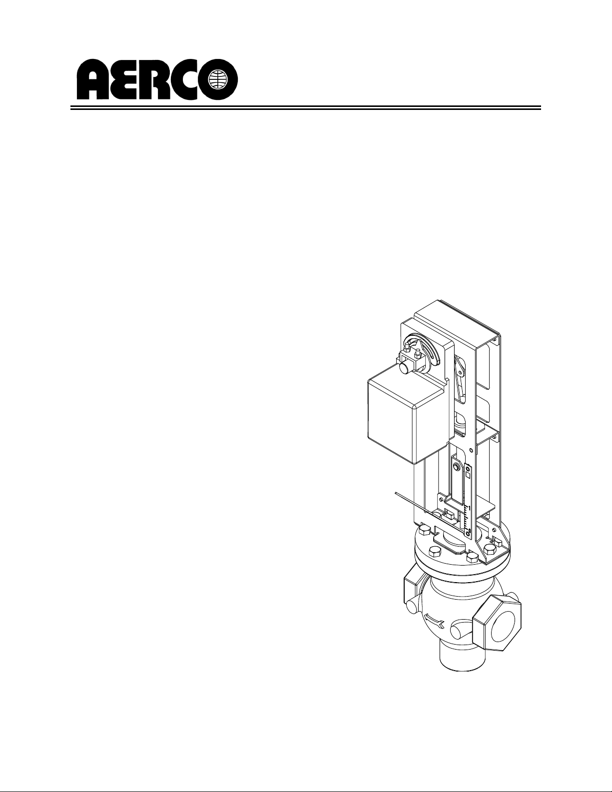
ELECTRONIC
CONTROL VALVE
Type CXT-E
Printed in U.S.A. REVISED 4/18/07
Page 2
Telephone Support
Direct to AERCO Technical Support
(8 to 5 pm EST, Monday through Friday)
(800) 526-0288
AERCO International, Inc.
159 Paris Avenue
Northvale, NJ 07647
www.aerco.com
© AERCO International, Inc., 2006
The information contained in this
installation, operation and maintenance
manual is subject to change without
notice from AERCO International, Inc.
AERCO makes no warranty of any kind
with respect to this material, including
but not limited to implied warranties of
merchantability and fitness for a particular application. AERCO International is
not liable for errors appearing in this
manual.
Page 3

VA-115 INSTRUCTIONS – ELECTRONIC CONTROL VALVE, CXT-E
TABLE OF CONTENTS
SECTION PAGE
SAFETY PRECAUTIONS iii
1 - GENERAL INFORMATION 1-1
2 - INSTALLATION 2-1
3 - ADJUSTMENT 3-1
4 - OPERATION 4-1
5 - FUNCTIONAL DESCRIPTION 5-1
6 - ROUTINE MAINTENANCE 6-1
7 - TROUBLESHOOTING 7-1
8 - CORRECTIVE MAINTENANCE 8-1
9 - RECOMMENDED SPARES
9-1
i
Page 4

VA-115 INSTRUCTIONS – ELECTRONIC CONTROL VALVE, CXT-E
LIST OF ILLUSTRATIONS
FIGURE TITLE PAGE
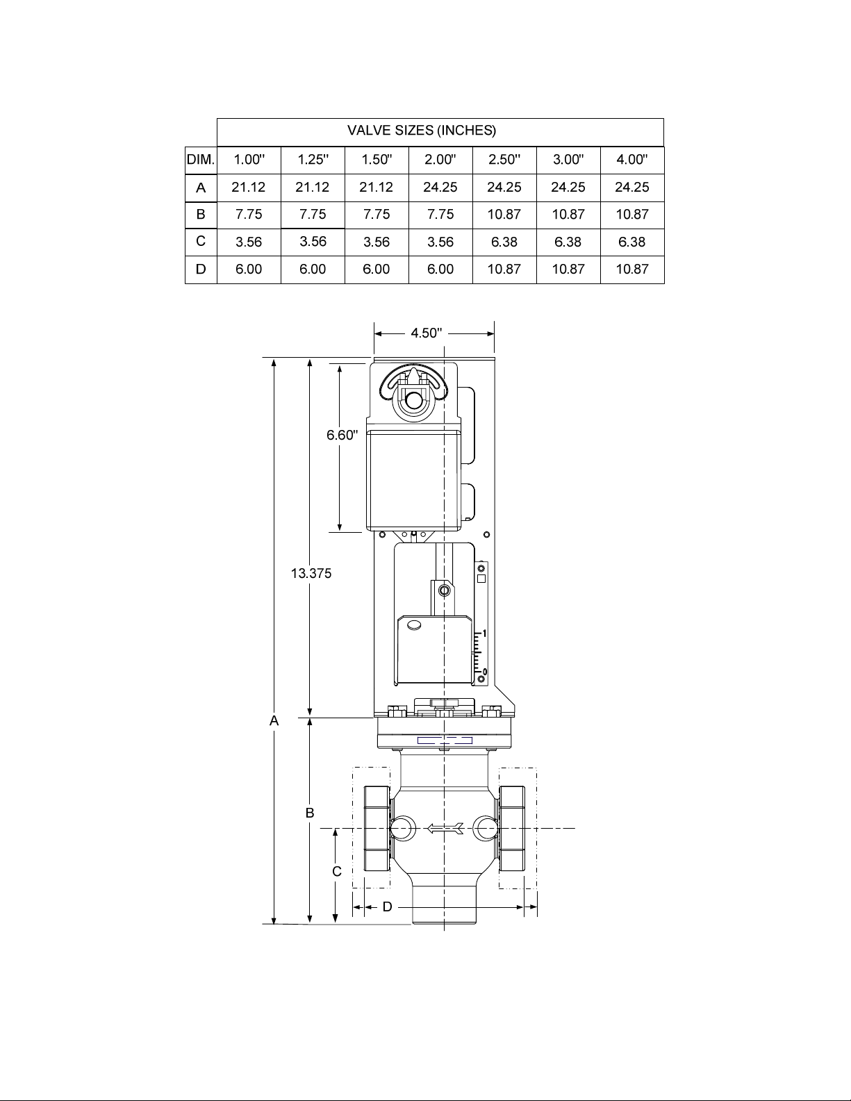
1-1 Reference Dimensions for AERCO Control Valves, Type CXT-E 1-2
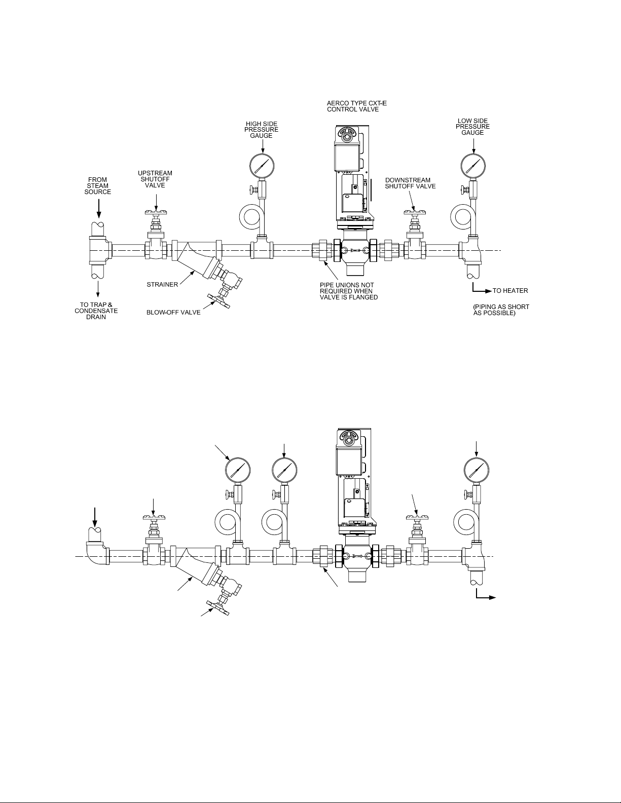
2-1 Recommended Control Valve, CXT-E Installation For Steam Flow 2-3
2-2 Recommended Control Valve, CXT-E Installation For Hot (Boiler)
Water Flow
3-1 Actuator Adjustment 3-2
5-1 Electronic Control Valve, Type CXT-E 5-1
6-1 Valve Shaft Seals 6-1
8-1 Valve Assemblies, Type CXT-E (Sizes 1.00” To 2.00”) 8-6
8-2 Valve Assemblies, Type CXT-E (Sizes 2.50” To 4.00”) 8-8
8-3 Cage Removal Tool 8-10
8-4 Linkage Assembly Installation Details 8-11
8-5 Actuator Replacement 8-13
8-6 Linkage Assemblies 8-14
2-3
ii
Page 5
VA-115 INSTRUCTIONS – ELECTRONIC CONTROL VALVE, CXT-E
SAFETY PRECAUTIONS
Installing or operating personnel must, at all times, observe all safety regulations.
The following warnings are general and must be given the same attention as
specific precautions included in the instructions
WARNING!
FLUIDS UNDER PRESSURE MAY CAUSE INJURY TO
PERSONNEL OR DAMAGE TO EQUIPMENT WHEN
RELEASED
CLOSE ALL SHUTOFF VALVES AND CAREFULLY
TRAPPED PRESSURES TO ZERO BEFORE PERFORMING ANY
MAINTENANCE. TAG THE PRESSURE SOURCE “OUT OF SERVICE” WHILE
PERFORMING MAINTENANCE TASKS.
DECREASE ALL
WARNING!
LIVE STEAM CAN CAUSE SEVERE BURNS
NEVER SEARCH FOR LEAKAGE IN A LIVE STEAM SYSTEM BY “FEEL”. USE
A MIRROR OR OTHER SUITABLE POLISHED OBJECT.
iii
Page 6

Page 7

VA-115 INSTRUCTIONS – ELECTRONIC CONTROL VALVE, CXT-E
1 - GENERAL INFORMATION
INTRODUCTION
This Instruction Manual provides installation, adjustment, operation and maintenance procedures for the
AERCO Electronic Control Valves, Type CXT-E. These Valves can be used for either steam flow or hot
(boiler) water flow applications.
If an AERCO Electronic Control System (ECS) is also included with the shipment, refer to AERCO
Instruction Manual AC-105. In addition to providing full coverage for the ECS, Instruction Manual AC-105
also includes all descriptions and procedures contained in this manual (VA-115).
ELECTRONIC CONTROL VALVE, TYPE CXT-E
Each Electronic Control Valve is comprised of three major sections; the Valve Body, the Linkage
Assembly and the Valve Actuator. The Control Valves are available in sizes ranging from 1 inch to 4
inches. An identical Actuator Assembly is used with each size Valve Body. The Linkage Assembly used
with each size Valve Body is identical, except for minor differences in the Shaft Adapter stroke of the
mechanical linkage. Figure 1-1 shows the basic dimensions for each size AERCO Electronic Control
Valve, Type CXT-E.
It should be noted that the Control Valves used for steam flow are identical to those used for hot (boiler)
water flow.
CONTROL VALVE ACCESSORIES
The accessories required for use with AERCO Electronic Control Valves, Type CXT-E will depend on the
specific application. Detailed installation instructions, including typical installation drawings are provided in
the INSTALLATION Section of this manual. However, please note the items listed below and ensure that
ALL mandatory items are available:
ACCESSORY
• Upstream Shutoff Valve
• Downstream Shutoff Valve
• Strainer and Blow-Off Valve
• High Side Pressure Gauge
• Low Side Pressure Gauge,
Compound Type for steam flow
If any of the above items have been furnished by AERCO with the CXT-E Control Valve, the necessary
drawings and/or instructions should be included with the shipment.
REQUIREMENT
- Mandatory
Suggested for ease of maintenance.
Required if a Bypass Line is used.
Mandatory
Recommended for adjustment and
maintenance
Recommended for adjustment and
maintenance.
1-1
Page 8
VA-115 INSTRUCTIONS – ELECTRONIC CONTROL VALVE, CXT-E
Figure 1-1. Reference Dimensions for AERCO Electronic Control Valves, Type CXT-E
1-2
Page 9

VA-115 INSTRUCTIONS – ELECTRONIC CONTROL VALVE, CXT-E
2 - INSTALLATION
INTRODUCTION
The installation procedures contained in this section apply to all sizes of AERCO Electronic Control
Valves, Type CXT-E, ranging from 1 inch to 4 inches. These procedures can be used for both steam and
hot (boiler) water flow systems.
ELECTRONIC CONTROL VALVE TYPE CXT-E INSTALLATION
Basically, the installation procedures for the Electronic Control Valve consist of:
• Installing the CXT-E Electronic Control Valve and associated steam or hot (boiler) water piping and
components.
• Connecting external electrical power and control signals to the Control Valve Actuator
Proceed as follows:
1. Refer to Figure 1-1 for dimensions of the Control Valve furnished with the Packaged Water Heater.
2. Next, refer to the recommended installation drawing in Figure 2-1 for steam flow, or Figure 2-2 for hot
(boiler) water flow.
3. Install the Control Valve with the Actuator Linkage in the vertical, upright position as shown in Figure
2-1 or 2-2.
4. For maintenance purposes, unions are required with threaded ends to simplify removal from the
steam or hot boiler water line.
5. Blow out all pipe lines to clear them of dirt chips, scale or other foreign matter which could adversely
affect Valve operation when in service.
6. Install an in-line strainer upstream of the Valve as shown in Figure 2-1 (steam) or Figure 2-2 (hot
boiler water). This will protect against foreign matter reaching the Valve during service operation.
7. If the Valve is controlling steam, ensure that the steam line is properly trapped to prevent
accumulation of condensate ahead of the Valve.
8. Install Shutoff Valves (metal-seated, gate-type) upstream and downstream of the Control Valve to
permit removal from the line for maintenance.
9. Pressure gauges should be installed on both sides of the Control Valve as shown in Figure 2-1
(steam) or Figure 2-2 (hot water).
2-1
Page 10

VA-115 INSTRUCTIONS – ELECTRONIC CONTROL VALVE, CXT-E
10. The gauge on the high pressure side of the Valve is for adjustment and maintenance purposes. The
gauge on the low pressure side is to ensure that the correct pressure is being introduced to the
Control Valve. For either steam or water flow, the low side gauge denotes the pressure of the fluid in
the line which may create a hazardous condition.
11. A temperature gauge should be installed in the high pressure side of a hot (boiler) water line as
shown in Figure 2-2.
CAUTION
DO NOT use the Actuator Linkage Frame at the top of the Control Valve Body for
leverage when installing the Control Valve. Use pipe wrenches on the inlet and
outlet hex of the Valve Body.
12. Install the Control Valve with the arrow on the Valve Body pointing in the direction of flow.
13. After the Control Valve has been installed in the steam or hot water line, ensure that all piping
connections are secure and leak tight..
14. If the Electronic Control Valve Type CXT-E is furnished separately, without an AERCO Electronic
Control System (ECS), electrical power and control signal connections must be made at the 3-pin
Molex connector as follows:
Pin 1 COMMON
Pin 2 +24 VDC
Pin 3 4–to-20 mA Control Signal
This completes the installation procedures for Control Valves shipped separately.
2-2
Page 11
VA-115 INSTRUCTIONS – ELECTRONIC CONTROL VALVE, CXT-E
WATER
SOURCE
Figure 2-1. Recommended Control Valve, CXT-E Installation For Steam Flow
AERCO TYPE CXT-E
FROM
UPSTREAM
SHUTOFF
VALVE
STRAINER
BLOW-OFF VALVE
TEMPERATURE
GAUGE
HIGH SIDE
PRESSURE
GAUGE
CONTROL VALVE
PIPE UNIONS NOT
REQUIRED WHEN
VALVE IS FLANGED
DOWNSTREAM
SHUTOFF VALVE
LOW SIDE
PRESSURE
GAUGE
TO HEATER
(PIPING AS SHORT
AS POSSIBLE)
Figure 2-2. Recommended Control Valve, CXT-E Installation For Hot (Boiler) Water Flow
2-3
Page 12

Page 13

VA-115 INSTRUCTIONS – ELECTRONIC CONTROL VALVE, CXT-E
3 - ADJUSTMENT
INTRODUCTION
Place the AERCO Heater (or other equipment being controlled) into operation in accordance with the
instructions furnished with the Heater (or other equipment).
WARNING
The Upstream Steam or Boiler Water Shutoff Valves MUST be closed prior to
performing the following adjustment procedures. Failure to observe this
WARNING may result in personal injury.
CONTROL VALVE TYPE CXT-E ADJUSTMENT
All CXT-E Actuators are powered by 24 VDC and are controlled by a linear 4-to-20 mA control signal. A 4
mA control signal input places the Control Valve in the fully-closed position; while a 20 mA signal strokes
the Valve to the fully-open position.
The Control Valve Actuators are self-calibrating for all Valve sizes. Therefore, simply proceed as follows
to automatically adjust the Actuator:
NOTE
The following adjustment procedure must be performed any time that the CXT-E Actuator
is replaced or a mechanical adjustment is made to the Linkage Assembly or Valve.
1. Refer to Figure 3-1 and loosen the Actuator cover set screw.
2. Remove the Actuator cover to access the PC Board containing the terminal connections, DIP
switches, Auto-Stroke (Reset) button and LED shown in Figure 3-1.
NOTE
If the Control Valve is furnished with an AERCO Electronic Control System (ECS), power
is applied to the Valve Actuator when the Control Box POWER switch is set to ON.
3. Apply 24 VDC power across Actuator pins 2 (+) and 1 (Common). The LED will light indicating that
power is applied. Wait approximately 10 seconds while the unit performs a self-test. Upon successful
completion of the self-test, the LED will blink 3 times and then go off.
4. For full-stroke automatic adjustment, press the Auto-Stroke (Reset) button. The LED will light.
5. The Actuator will then rotate in both directions to find its open and closed Valve position stops.
6. Upon successful completion of the automatic adjustment, the LED will blink 3 times and then go off..
7. Turn off power to the Actuator. Replace and secure the cover by tightening the set screw.
3-1
Page 14

VA-115 INSTRUCTIONS – ELECTRONIC CONTROL VALVE, CXT-E
ACTUATOR
0
neptronic
1 2 3
90
COVER
SET SCREW
PC BOARD
TERMINALS
34 5
12
AUTO-STROKE
(RESET) BUTTON
LED
123
DIP SWITCHES (3)
(ALL IN UP POSITION)
Figure 3-1. Actuator Adjustment
3-2
Page 15

VA-115 INSTRUCTIONS – ELECTRONIC CONTROL VALVE, CXT-E
4 - OPERATION
This Section provides the basic checks and initial startup for the CXT-E Control Valve and Heater (or
other equipment) being controlled.
OP1. Refer to Figure 2-1 (Steam Flow) or Figure 2-2 (Hot Water Flow). To place the Control Valve and
Heater System into operation, proceed as follows:
a. Ensure that the AERCO Heater (or other equipment) is ready for operation in accordance
with the instructions provided with the Heater.
b. First, slowly open the upstream and the downstream shutoff valves.
c. Ensure that electrical input power is properly connected to the Electronic Control Valve, Type
CXT-E and ECS Control System.
d. Ensure that a 4-to 20 mA control signal is being supplied to pin 3 of the Control Valve
connector.
OP2. If it becomes necessary to take the Control Valve and Heater System out of operation, close the
upstream, downstream shutoff valves.
OP3. If the Control Valve/Heater System is not maintaining the desired setpoint temperature, refer to
Section 7 – TROUBLESHOOTING.
4-1
Page 16

Page 17

VA-115 INSTRUCTIONS – ELECTRONIC CONTROL VALVE, CXT-E
5 - FUNCTIONAL DESCRIPTION
INTRODUCTION
The AERCO Electronic Control Valves, Type CXT-E are highly responsive devices which precisely
modulate the position of the Valve shaft based on the control signal input. As mentioned in Section 1,
each Control Valve consists of a Valve Body, Linkage Assembly and Actuator. Figure 5-1 illustrates the
three major assemblies of the Control Valve. The following paragraphs provide a brief functional overview
of the Electronic Control Valve, Type CXT-E.
FUNCTIONAL OVERVIEW
All Control Valves, Type CXT-E, regardless of size, utilize identical Actuators (Part No. 69009). The
Actuator is mounted on the upper portion of the Linkage Assembly and is secured to the Linkage shaft
(Figure 5-1). An Adapter is used to secure the Linkage to the Valve Body Shaft. The Valve Actuator is
powered by 24 VDC and is controlled by a linear 4-to-20 mA control signal input from the external
Temperature Controller. A 4 mA control signal corresponds to a fully closed valve position, while a 20 mA
signal corresponds to a fully open position.
As described in Section 3 (Adjustment), the Control Valve Actuator is self-calibrating for all sizes of
AERCO Control Valves. The CXT-E Valve Actuator also incorporates a fail-safe mechanism which
automatically closes the Control Valve in the event of a loss of input power loss or control signal.
LINKAGE
LINKAGE
SHAFT
ASSEMBLY
MECHANICAL
LINKAGE
ACTUATOR
LINKAGE
ADAPTER
VALVE
SHAFT
VALVE
BODY
Figure 5-1. Electronic Control Valve, Type CXT-E
5-1
Page 18

Page 19

VA-115 INSTRUCTIONS – ELECTRONIC CONTROL VALVE, CXT-E
6 - ROUTINE MAINTENANCE
INTRODUCTION
The following paragraphs provide the AERCO recommended routine maintenance procedures for the
Electronic Control Valve Type CXT-E and the Electronic Control System (ECS).
CXT-E CONTROL VALVE ROUTINE MAINTENANCE
MONTHLY
Once each month, check the Control Valve for leakage as follows:
1. Refer to Figure 6-1 and check the Packing Nut and Valve Top for evidence of leakage.
2. If there is leakage between the Packing Nut and Valve Top, tighten the Packing Nut until the leakage
stops. DO NOT FORCE the Packing Nut.
3. If tightening the Packing Nut does not stop the leak, the Packing Nut and Packing Assembly must be
replace in accordance with the procedures specified in the Control Valve CORRECTIVE
MAINTENANCE Section.
Figure 6-1. Valve Shaft Seals
SEMI-ANNUALLY
Every six months, check the following items:
1. Refer to Section 3 - ADJUSTMENT and perform the Actuator adjustment procedure specified. Verify
that the Actuator strokes the Control Valve from the fully closed to the fully open position.
2. Clean the Strainer in the heating fluid line (Figure 2-1 or Figure 2-2) in accordance with the
instructions furnished with the Strainer.
6-1
Page 20

Page 21

VA-115 INSTRUCTIONS – ELECTRONIC CONTROL VALVE, CXT-E
7 - TROUBLESHOOTING
INTRODUCTION
This Section provides the troubleshooting procedures necessary to isolate faults to the most probable
cause(s) for a malfunction of the Electronic Control Valve, Type CXT-E. Prior to performing the
troubleshooting steps and procedures specified in this Section, perform the following preliminary checks:
NOTE
In addition to the procedures contained in this Section, also check the Troubleshooting
Sections of the AERCO Heat Exchanger Manual (if used) or any other ancillary
equipment manuals included with the installation configuration.
1. Verify that all piping connections have been made in accordance with Figure 2-1 (Steam Flow) or
Figure 2-2 (Hot (Boiler) Water Flow).
2. Ensure that the Control Valve is installed with the flow arrow on the Valve Body pointing in the
direction of flow.
3. Ensure that both the upstream and downstream shutoff valves are fully open.
4. Check to ensure that the 3-pin Molex connector on the CXT-E Actuator is properly connected to an
AERCO Electronic Control System (ECS) or other type of Controller being used. Proper electrical
connections are as follows:
• Pin 1: Common
• Pin 2: +24 VDC
• Pin 3: 4-20 mA Control Signal
TROUBLESHOOTING PROCEDURES
The troubleshooting procedures for the Control Valve, Type CXT-E are provided in Table 7-1. When a
fault occurs, proceed as follows:
1. Refer to the FAULT INDICATION column in the Table 7-1 and locate the fault that best describes the
existing conditions.
2. Proceed to the PROBABLE CAUSE column and, if more than one item is listed, start with the first
item shown for the fault condition.
3. Perform the corresponding checks and procedures listed in the CORRECTIVE ACTION column for
the first PROBABLE CAUSE.
4. Continue checking each additional PROBABLE CAUSE for the existing fault until the fault has been
corrected.
5. Refer to the applicable procedures in Section 8 – CORRECTIVE MAINTENANCE if component
removal and/or replacement is required.
7-1
Page 22

VA-115 INSTRUCTIONS – ELECTRONIC CONTROL VALVE, CXT-E
TABLE 7-1. TROUBLESHOOTING – CONTROL VALVE CXT-E
NO. FAULT INDICATION PROBABLE CAUSE CORRECTIVE ACTION
T1 System not operating.
Control Valve is closed
and outlet water temp. is
far below setpoint.
T2 System over-heats by
more than 10°F above the
desired setpoint.
Outlet temp is below OverTemp limit setting
CAUTION
Over-tightening the Packing Nut may trap the Valve
Stem and slow or stop
Valve motion.
1. No power supplied to
Control Valve
2. Control signal not
being supplied from
Temp. Controller.
1. Control Valve not fully
closed.
2. Temp. Controller not
set properly or
defective.
3. Valve Actuator not
properly secured to
Linkage Assembly.
1. Disconnect Valve Actuator plug and
verify that 24 VDC power is present at
pin 2 of Actuator cable. Restore power
if necessary. If System includes an
over-temp limiting device, ensure that it
has not tripped.
2. Verify presence of 4 - 20 mA control
signal at pin 3 of Actuator cable. If
control signal is not present,
troubleshoot Temp. Controller.
1. Check the 4 – 20 mA control signal
being supplied to Actuator. If signal is
greater than 4 mA when heater outlet
temperature is 10°F (or more) above
the desired setpoint, proceed to next
item in list.
2. Check the current setting of Temp.
Controller providing the 4 – 20 mA
control signal to the Valve Actuator.
Readjust if necessary. If adjustment
does not clear fault, troubleshoot the
Controller.
3. Check Actuator U-bolt securing it to
Linkage Assembly. Tighten if needed
and readjust the CXT-E Control Valve
per Section 3.
T3 System outlet water
temperature is below
desired setpoint
CAUTION
Over-tightening the Packing Nut may trap the
Valve Stem and slow or
stop Valve motion.
4. Foreign matter in
Valve Seat.
1. Temp. Controller not
properly set.
2. Control Valve not
opening properly.
7-2
4. If Valve still does not close after
checking the above items, disassemble
the Valve and clean the Seat per steps
CM18 – CM28 in Section 8. Readjust
the CXT-E Control Valve per Section 3.
1. Check the current setting of the Temp.
Controller. If the setting is below the
desired setpoint, readjust as necessary.
2. Check as follows:
a. Ensure Actuator is secured to
Linkage Assembly. Tighten if needed
and readjust the CXT-E Control
Valve per Section 3.
b. Verify that 24 VDC power and 4 – 20
mA control signal are present at
Actuator pins 2 and 3 respectively.
c. To ensure Valve is not binding,
check Seal Retainer per steps CM1CM10 of Section 8 Corrective
Maintenance. Replace items as
necessary.
Page 23

VA-115 INSTRUCTIONS – ELECTRONIC CONTROL VALVE, CXT-E
TABLE 7-1. TROUBLESHOOTING – CONTROL VALVE CXT-E (Continued)
NO. FAULT INDICATION PROBABLE CAUSE CORRECTIVE ACTION
T3 (Continued) 3. Steam pressure, or
heating fluid
temperature too low.
4. For Steam Heating
System, Trap or
Orifice in Heater
Condensate Line is
malfunctioning.
3. Check the high side steam pressure to
the Control Valve to ensure it is correct.
For high temperature (HT) water,
ensure there is good circulation.
a. If steam pressure or HT water
temperature is lower than the system
design spec., correct as necessary.
b. If high side steam pressure drops, or
there is no HT water circulation as
the Control Valve opens, there may
be a partially closed valve in the
upstream line. Also, the strainer may
be clogged. Correct as needed.
4. Check for improper operation of Trap or
clogged Orifice in Condensate Line as
follows:
a. If low side pressure gauge shows
pressure but steam does not heat
properly, CAREFULLY break
Condensate Line connection AHEAD
of Trap or Orifice.
b. Allow condensate to run out into floor
drain.
c. If Heater outlet temperature rises to
desired setpoint with condensate
connection open, repair or replace
Trap or unplug Orifice.
T4 Wide variations in
Heater outlet temperature during wide
variations in flow .
T5 Rapid fluctuations in
heater outlet temperature which do not
load changes
follow
1. System not properly
sized to maintain
desired setpoint.
1. Temp. Controller
sensitivity not set
correctly
2. Steam System Trap
or Orifice fault
7-3
1. Review system flow characteristics to
ensure Heat Exchanger and Valve are
properly sized to maintain the desired
outlet temperature.
1. Adjust Temp. Controller sensitivity
2. Refer to T3, Corrective Action 4 above
and proceed as indicated.
Page 24

Page 25

VA-115 INSTRUCTIONS – ELECTRONIC CONTROL VALVE, CXT-E
8 - CORRECTIVE MAINTENANCE
INTRODUCTION
This Section provides corrective maintenance for all sizes of Electronic Control Valves, Type CXT-E
CXT-E CONTROL VALVE CORRECTIVE MAINTENANCE
The corrective maintenance procedures for the Electronic Control Valve are divided into the following
major areas:
• Valve Shaft Seal Retainer Replacement
• Valve Disassembly
• Valve Reassembly
• Actuator Replacement
• Linkage Replacement
Refer to the applicable paragraphs which follow and perform the Corrective Maintenance steps indicated.
VALVE SHAFT SEAL RETAINER REPLACEMENT
Refer to Figure 8-1 or Figure 8-2 and proceed as follows:
WARNING
Ensure that the Control Valve has been isolated from the steam or hot (boiler)
water supply. Live steam or hot water can cause serious burns to personnel.
WARNING
Ensure that all electrical power to the Control Valve Actuator has been
disconnected. Serious personal injury may result if this Warning is not observed.
CM1. Loosen the Hex Nuts (17) under the Indicator Plate (Figure 8-1 or 8-2) approximately a half turn
clockwise.
CM2. Disconnect the Linkage Adapter from the Valve Shaft (16) by turning the Shaft clockwise (as
viewed from above). If the Valve Shaft cannot be turned by hand, use an open-end wrench to turn
the “double-nuts” on the Shaft until it disengages the Linkage Adapter threads.
CM3. Remove the Indicator Plate from the Valve Shaft (16).
CM4. Remove the two Cap Screws (19) securing the Linkage Assembly (26) to the Valve Top (21).
CM5. Remove the complete Linkage Assembly (26), with the Actuator Assembly (27) still attached,
from the Valve Top. Also, remove the Gasket (29).
CM6. If the Packing Nut (18) is faulty (leaking or binding the Shaft (16), it must be replaced.
CM7. Measure and record the current position of the Hex Nuts (17) from the end of the Valve Shaft.
This will simplify adjustment of the Actuator Linkage during reassembly.
8-1
Page 26

CM8. Next, completely remove the Hex Nuts (17) from the Valve Shaft (16).
CM9. Remove the Packing Nut (18) and the Packing Assembly (20) from the Valve Body.
CAUTION
Over-tightening the Packing Nut (18) may trap the Valve Stem and slow or stop Valve
motion.
CM10. Replace BOTH the Packing Nut (18) and the Packing Assembly (20) with a NEW Packing Nut
and Packing Assembly.
CM11. Replace the Hex Nuts (17) onto the Valve Body Shaft (25) and position them in the same location
noted in step CM7.
CM12. Attach the Actuator (27), Linkage (26) and Gasket (29) to the Valve Top using the two Cap
Screws (19) provided.
CM13. Install the Indicator Plate on the Valve Lower Shaft (16) and secure it in place with the Linkage
Adapter.
CM14. Reconnect the Linkage Adapter to the Linkage Shaft by replacing the Shaft Pin.
VALVE DISASSEMBLY
Refer to Figure 8-1, or Figure 8-2 and proceed as follows:
CM15. Close the upstream and downstream shutoff valves before and after the Control Valve. If it is
necessary to keep the Heater in operation, proceed in accordance with step OP3 in the
OPERATING Section of this manual before continuing. If not, proceed directly to the next step.
CM16. If the Control Valve is easily accessible for disassembly and reassembly, leave it installed in the
fluid line. If it is not easily accessible, remove the Valve from the line and clamp it in a bench vise
for easy accessibility.
CM17. Completely remove the Actuator (27) and Linkage Assembly (26) from the Valve Body as
described in steps CM1 through CM5.
CM18. Refer to Figure 8-1 or Figure 8-2. It is strongly recommended that disassembly of the Valve be
limited to only the steps necessary to restore the Valve to proper operation. However, the
following steps cover complete disassembly, if necessary. When performing Valve disassembly,
USE EXTREME CARE not to mar or scratch any surfaces. The following steps assume that the
Actuator and Linkage Assemblies have already been removed from the Valve Body.
CM19. Remove the following parts in the order specified:
CAUTION
CAREFULLY remove the Packing Nut (18) and Cap Screws (14) indicated below
to relieve any trapped pressure.
• Hex Nuts (17)
• Packing Nut (18)
• Packing Assembly (20)
• Cap Screws (14)
• Valve Top (21)
• Valve Top Gasket (13)
8-2
Page 27

VA-115 INSTRUCTIONS – ELECTRONIC CONTROL VALVE, CXT-E
CM20. Grasp the Lower Shaft (16) and carefully lift out the ENTIRE Shaft/Seat/Piston Assembly.
CM21. For Control Valves, 1-inch through 2-inch (Figure 8-1), disassemble the Shaft/Seat/Piston
assembly in the following order:
• Lock Washer (23)
• Retaining Ring (11)
• Pilot Spring (10)
• Valve Stem Retaining Nut (35)
• Lower Shaft (16) and Valve Stem (12)
• Retaining Disc (8)
• Disc Seat (7)
• Seat Retainer (34)
• Valve Plug Shaft (5)
CM22. For Control Valves, 2.5-inch, 3-inch and 4-inch, (refer to Figure 8-2), disassemble the
Shaft/Seat/Piston Assembly in the following order:
• Lock Washer (23)
• Pilot Spring Retainer (11)
• Pilot Spring Back-Up Washer (31), 4-inch Valve only
• Pilot Spring (10)
• Cap Screws (9)
• Retaining Disc (8)
• Lower Shaft (16) and Valve Stern (12)
• Valve Seat (7)
• Top Piston (6) and Bottom Piston (3) assembly
CM23. It is recommended that the Seat Cage (2) NOT BE DISASSEMBLED unless it must be replaced.
See Step CM29.
NOTE
In any cleaning operation called for in these instructions, ALWAYS clean all
denoted parts thoroughly of all dirt and scale. Always use a clean cloth and, if
necessary, a solvent. NEVER use emery cloth or sandpaper unless instructed
otherwise herein.
CM24. CLEAN ALL PARTS THOROUGHLY. ALL DIRT AND/OR SCALE MUST BE REMOVED from the
outer surfaces of the Valve Plug Shaft (5) (Figure 8-1) or the Top Piston (6) and Bottom Piston (3)
(Figure 8-2) and from the surface of the Valve Stem (12).
CM25. Inspect the Valve Stem (12). If it is damaged or it does not seat properly on the Valve Seat (7), or
does not move freely in the Valve Seat Retaining Disc (8), the Valve Stem (12), Pilot Spring
Retainer (11) and Pilot Spring (10) must be replaced.
CM26. Inspect the outer surfaces of the Valve Plug (5) or the Top Piston (6) and Bottom Piston (3). If
they are scored or damaged so that they will not move freely up and down in the Seat Cage (2),
the Valve Plug or Pistons must be replaced. Also see Step CM32.
8-3
Page 28

CM27. Inspect the Valve Seat (7). If it is worn so that it will not seat properly with the Seat Cage (2), with
the Valve Stem (12), it must be replaced.
CM28. THOROUGHLY clean and inspect the seating and inner surfaces of the Seat Cage (2). If the
seating surface around the top of the Cage is worn or damaged so that the Valve Seat (7) will not
seat properly, or if the inner surfaces of the Cage are scored or damaged so that the Valve Plug
(5) or Pistons (3) and (6) will not move up and down freely, the Cage (2) must be replaced.
CM29. If the Cage (2) must be removed from the Valve Body (1), it will be necessary to fabricate a tool,
such as shown in Figure 8-3 for Cage removal. Insert the tool into the slots on top of the Cage (2)
and turn the Cage out of the Valve Body. To obtain a Cage Removal tool, contact AERCO or your
nearest Sales Representative.
VALVE REASSEMBLY
Refer to Figure 8-1 or Figure 8-2 when performing the following procedures.
CM30. If the Seat Cage has been removed, place a NEW Seat Cage Gasket (24) on the seating surface
of the Valve Body. Next, replace the Seat Cage (2) into the Valve Body (1), using the tool
described in Step CM29. Make the Seat Cage tight.
CM31. If disassembled or being replaced, reassemble the Top Piston (6) and Bottom Piston (3) onto the
Valve Plug Shaft (5), using the Top Piston Retaining Nut (46) (1-inch through 2-inch Valves), and
Bottom Piston Retaining Nut (50) or Bottom Piston Retaining Ring (4).
CM32. For Control Valves, 1-inch through 2-inch, (Figure 8-1), reassemble the Valve Plug/Seat/Shaft
assembly in the following order:
• Valve Plug (5)
• Seat Retainer (34)
• Valve Seat (7)
• Retaining Disc (8)
• Valve Stem (12) and Lower Shaft (16)
• Valve Stem Retaining Nut (35)
• Pilot Spring (10)
• Pilot Spring Retaining Clip (3)
• Lock Washer (23)
CM33. For Control Valves, 2.5-inch, 3-inch and 4-inch, (Figure 8-2), reassemble the Piston/Seat/Shaft
assembly in the following order:
• Top Piston (6) and Bottom Piston (3) assembly
• Valve Seat (7)
• Valve Stem (12) and Lower Shaft (16)
• Valve Seat Retaining Disc (8)
• Cap Screws (9)
• Pilot Spring (10)
• Pilot Spring Back-Up Washer (31), 4-inch Valve only
• Pilot Spring Retainer (11)
• Lock Washer (23)
8-4
Page 29

VA-115 INSTRUCTIONS – ELECTRONIC CONTROL VALVE, CXT-E
CM34. Holding the Lower Shaft (16), carefully replace the entire Shaft/Seat/Piston assembly into the Valve
Body (1) and Seat Cage (2).
CM35. Thoroughly clean the gasket surfaces of the Valve Body (1) and Valve Top (21) of all dirt and
scale. If necessary, use a wire brush, emery or both.
CM36. See Figure 8-1 or 8-2. Reassemble these parts in the following order:
• NEW Valve Top Gasket (13)
• Valve Top (21)
• Cap Screws or Hex Hd. Bolts (14) – Valve sizes 2-1/2” to 4” use 1/2”-13 Cap Screws. Valve
sizes 1” to 2” use 3/8”-16 Hex Hd. Bolts. Tighten using an alternating pattern to provide a
uniform seal and prevent Valve leakage.
• NEW Packing Assembly (20)
• Packing Nut (18)
• Hex Nuts (17)
• Indicator Plate (See Figure 8-1 or 8-2)
CM37. Replace the Actuator (27), Linkage (26) and Gasket (29) onto the Valve Top (21) and secure with
Cap Screws (19).
CM38. Position the Hex Nuts (17) at the original location noted during the removal process.
CM39. Install the Indicator Plate on the Valve Shaft (16) with the curved end facing upward (Figure 8-4).
CM40. Attach the Valve Shaft (16) to the Linkage Adapter by rotating the Shaft counterclockwise (as
viewed from above). If the Valve Shaft cannot be turned by hand, use an open-end wrench to turn
the “double-nuts” on the Shaft until it engages the Linkage adapter threads. Insert the Shaft into
the Linkage Adapter until the Hex Nuts (17) are snug against the Indicator Plate.
CM41. Press down on the Valve Shaft (16) to compress the Pilot Spring (10) in the Valve Body.
CM42. With the Pilot Spring compressed, verify that the Indicator Plate is aligned with the “0” (zero)
marking on the Scale (28). If necessary, rotate the Valve Shaft until the Plate is aligned with the
“0” Scale marking.
CM43. If the Valve had been removed from the heating fluid line, replace it in. the line. Reconnect the
electrical connector plug to the Actuator.
CM44. Prior to placing the Valve back into service, perform the Control Valve Adjustment procedure in
Section 3.
8-5
Page 30

Figure 8-1. Valve Assemblies, Type CXT-E (Sizes 1.00” To 2.00”)
8-6
Page 31

VA-115 INSTRUCTIONS – ELECTRONIC CONTROL VALVE, CXT-E
PARTS LIST TABLE FOR VALVE ASSEMBLIES, TYPE CXT-E ( SIZES 1.00” TO 2.00”)
VALVE SIZE AND PART NUMBERS
ITEM QTY PART NAME 1.00 INCH 1.25 INCH 1.50 INCH 2.00 INCH
1 1 VALVE BODY 20762 20759 20758 20761
2 1 SEAT CAGE 16844 16845 16837 16843
3 1 BOTTOM PISTON 121540 121525 121502 121529
4 NOT USED
5 1 VALVE PLUG SHAFT 16849 16839 16838 16848
6 1 TOP PISTON 121539 12154 121501 121530
7 1 DISC SEAT 121541 121527 121510 121531
8 1 RETAINING DISC 121542 121513 121504 121532
9 NOT USED
10 PILOT SPRING 121528 121528 121528 121528
11 1 RETAINING RING 121545 121545 121545 121545
12 1 VALVE STEM 122655 122654 122651 122650
13 1 VALVE TOP GASKET 122136 122136 122136 122136
14 6 BOLT, HEX, 3/8-16 122405 122405 122405 122405
16 1 LOWER SHAFT 121979 121980 121980 121982
17 2 HEX NUT, 1/4-20 6-226 6-226 6-226 6-226
18 1 PACKING NUT 122664 122664 122664 122664
19 2 BOLT, HEX 3/8-16 x 5/8 LG 54014 54014 54014 54014
20 1 PACKING ASSY 121567 121567 121567 121567
21 1 VALVE TOP 16943 16943 16943 16943
22 NOT USED
23 1 LOCKWASHER 122666 122666 122666 122666
24 1 SEAT CAGE GASKET 123080 123081 123082 123083
26 1 LINKAGE 24038-1 24038-1 24038-1 24038-1
27 1 ACTUATOR 69009 69009 69009 69009
28 1 SCALE 59028-1 59028-1.25 59028-1.5 59028-2
29 1 GASKET 81046 81046 81046 81046
30 2 NUT, HEX, #8-32 123322 123322 123322 123322
31 1
32 1 TOP PISTON RETAINING NUT 121543 121543 121543 121543
33 1 LOWER PILOT SEAT ASSY 121505 121505 121505 121505
34 1 SEAT RETAINER N/A 121559 121506 121506
35 1 VALVE STEM RETAINING NUT 121503 121503 121503 121503
BOTTOM PISTON RETAINING NUT
122982 122982 122982 122982
8-7
Page 32

ACTUATOR
27
LINKAGE
26
SHAFT PIN
LINKAGE ADAPTER
OR
17
16
18
19
29
15
20
21
23
31
22
30
28
0
INDICATOR PLATE
14
13
12
11
10
9
8
24
3
2
1
Figure 8-2. Valve Assemblies, Type CXT-E (Sizes 2.50” To 4.00”)
8-8
7
6
5
4
Page 33

VA-115 INSTRUCTIONS – ELECTRONIC CONTROL VALVE, CXT-E
PARTS LIST TABLE FOR VALVE ASSEMBLIES, TYPE CXT-E ( SIZES 2.50” TO 4.00”)
VALVE SIZE AND PART NUMBERS
ITEM QTY PART NAME 2.50 INCH 3.00 INCH 4.00 INCH
1 1 VALVE BODY 20765-1 20766-1 20775
2 1 SEAT CAGE 16961 161004 161046
3 1 BOTTOM PISTON 16962 161007 161048
4 1 PISTON RETAINING RING 122173 122173 122234
5 1 VALVE PLUG SHAFT 16972 161006 161047
6 1 TOP PISTON 16970 161005 161050
7 1 VALVE SEAT 121935 122032 122178
8 1 VALVE SEAT RETAINING DISC 121934 122031 122177
9 4 10-32 x 3/4” LG. SOCKET HD. CAP
SCREW
10 1 PILOT SPRING 122081 122232 121823
11 1 PILOT SPRING RETAINER 122082 122082 122173
12 1 VALVE STEM 122648 122658 122659
13 1 VALVE TOP GASKET 122083 122204 122203
122174 122174 122238
14 4 CAP SCREW 5/8-11 x 1-1/2” LG. N/A 6-310 6-310
15 2 3/8-16 NUT (4” VALVE ONLY) N/A N/A 6-264
16 1 LOWER SHAFT 122223 122230 122224
17 2 1/4-20 NUT 6-226 6-226 N/A
18 1 PACKING NUT 122664 122665 122665
19 2 3/8-16 x 5/8” LG. CAP SREWS 54014 54014 54014
20 1 PACKING ASSY 121567 121568 121568
21 1 VALVE TOP 18781 18823 18824
22 1 SEAT BACK-UP RING 122326 122327 122328
23 1 LOCKWASHER 122666 122667 122667
24 1 SEAT CAGE GASKET 123084 123085 123086
25 2 1/4” HEX HD. NPT PLUG 9-22 9-22 9-22
26 1 LINKAGE 24038-1 24038-1 24038-2
27 1 ACTUATOR 69009 69009 69009
28 1 SCALE 59028-2.50 59028-3 59028-4
29 1 GASKET 81046 81046 81046
30 2 8-32 HEX NUT 123332 123322 123322
31 1 PILOT SPRING BACKUP WASHER N/A N/A 122246
8-9
Page 34

VA-115 INSTRUCTIONS – ELECTRONIC CONTROL VALVE, CXT-E
BAR 1/4" SQUARE
TOOL STEEL
WELD ON INSIDE
ONLY
VALVE SIZE
1-INCH
1-1/4 INCH
1-1/2-INCH
2-INCH
2-1/2-INCH
3-INCH
ALL DIMENSIONS SHOWN ARE IN INCHES
C
B
1.25" 1.50"
PIPE OR TUBING - A
1" SCH. 40 PIPE
1-1/4" SCH. 40 PIPE
1-1/2" SCH. 40 PIPE
2-1/2" OD x .120" WALL
SEAMLESS STEEL
TUBING
2-1/2" OD x .120" WALL
SEAMLESS STEEL
TUBING
3" OD x .120" WALL
SEAMLESS STEEL
TUBING
A
D
HANDLE – 1 /2" DIA
COLD ROLLED STEEL
WELD
WELD
B
1.11 1-5/8 7-1/2
1.42
1.67
2.40
2.895
3.476
C D
2
2-3/8
2-5/8
3-3/8
3-15/16
7-1/2
8-1/4
8-1/4
9-1/2
8
8
1/2" STEEL
PLATE
TOOLS FOR 1-INCH TO 3-INCH VALVES
1/4" SQUARE BAR
TOOL STEEL
5
4-1/2
1/4
WELD
WELD
TOOL FOR 4-INCH VALVE ONLY
Figure 8-3. Cage Removal Tool
8-10
1/2
1
2" SCH. 40 PIPE
8
Page 35

VA-115 INSTRUCTIONS – ELECTRONIC CONTROL VALVE, CXT-E
ITEM QTY PART DESCRIPTION PART NUMBER
1 1 LINKAGE ASSEMBLY 24038-1 (1” TO 3” VALVES)
24038-2 (4” Valve)
2 1 SCALE 59028-1 (1” VALVE)
59028-1.25 (1.25” VALVE)
59028-1.5 (1.5” VALVE)
59028-2 (2” VALVE)
59028-2.5 (2.5” VALVE)
59028-3 ( 3” VALVE)
59028-4 (4” VALVE)
3 2 HEX NUT, 8-32 123322
4 2 CAP SCREW, 3/8-16 x 5/8 LONG 54014
5 1 LINKAGE GASKET 81046
Figure 8-4. Linkage Assembly Installation Details
8-11
Page 36

VA-115 INSTRUCTIONS – ELECTRONIC CONTROL VALVE, CXT-E
ACTUATOR REPLACEMENT
There are no repairable parts contained in the Actuator. Therefore, if the Troubleshooting procedures in
this Instruction Manual isolate the cause of the fault to the Actuator, it must be replaced as described in
the following steps:
CM45. Disconnect and lock-out/tag-out AC power going to the Control Box. Use a voltmeter to ensure
that all voltages are zero before continuing.
CM46. Disconnect the cable connected to the Actuator.
CM47. Using an 8 mm wrench, loosen the hex nuts securing the Actuator to the Linkage Shaft.
CM48. Completely remove the defective Actuator from the shaft.
CM49. To install the replacement Actuator, depress and hold the Clutch button (Figure 8-5) and rotate
the pointer to approximately 80° on the dial. Release the Clutch.
CM50. Next, slide the Actuator onto the Linkage Shaft.
CM51. Ensure that the pin on the Linkage Assembly is inserted in the center slot on the bottom of the
Actuator (Figure 8-5).
CM52. Verify that the indicator plate on the Linkage Assembly is aligned with the 0 (zero) marking on the
Linkage scale. Also, ensure that the Actuator Dial is approximately at the 80° position.
CM53. Ensure that the Pin on the Linkage is inserted in the center slot on the Actuator.
CM54. Using an 8 mm wrench, tighten the hex nuts on the U-bolt to secure the Actuator to the shaft.
Torque nuts to 60 in-lbs.
CM55. Reconnect the Control Box cable to the Actuator.
CM56. Following Actuator replacement, perform the Control Valve Adjustment procedure in Section 3.
8-12
Page 37

VA-115 INSTRUCTIONS – ELECTRONIC CONTROL VALVE, CXT-E
DIAL &
POINTER
9
0
LINKAGE
SHAFT
COVER
0
CLUTCH
neptronic
COVER
SET SCREW
CABLE
CONNECTOR
1 2 3
CENTER
SLOT
Figure 8-5. Actuator Replacement
LINKAGE ASSEMBLY REPLACEMENT
As Figure 8-6 shows, the Linkage Assembly Part No. will vary, depending on valve size. CXT-E valve
sizes from 1.00 to 3.00 inches utilize Linkage Assembly Part No. 24038-1. However, 4.00 inch CXT-E
Valves utilize Linkage Assembly Part No. 24038-2. The primary difference between the 24038-1 and
24038-2 Linkage Assemblies is the Adapter shown in Figure 8-6. In addition, the Linkage Pin location for
the 24038-1 assembly will vary for 1.00 to 2.00 inch valves and for 2.50 to 3.00 inch valves. IT IS
IMPERATIVE THAT THE CORRECT ADAPTER AND PIN LOCATION BE USED FOR THE VALVE SIZE
BEING REPAIRED. The Linkage Assembly is attached to the Control Valve Top with two Cap Screws.
The Linkage Gasket (Part No. 81046) should also be replaced when installing a new Linkage Assembly.
8-13
Page 38

VA-115 INSTRUCTIONS – ELECTRONIC CONTROL VALVE, CXT-E
Figure 8-6. Linkage Assemblies
If necessary, the Linkage Assembly is removed and replaced as follows:
CM57. Remove the Actuator using steps CM45 through CM48 in the previous paragraph titled
ACTUATOR REPLACEMENT.
CM58. Next, refer to Figure 8-1 (1” to 2” Valves or 8-2 (2 ½” to 4” Valves) to locate item numbers shown
in parentheses in the following steps.
CM59. Loosen the Hex Nuts (17) under the Indicator Plate (Figure 8-1 or 8-2) approximately a half turn
clockwise. To simplify Linkage Assembly replacement, DO NOT remove the Hex Nuts. This will
simplify adjustment of the Linkage during reassembly.
CM60. Remove the Shaft Pin (Figure 8-1 or 8-2) securing the Linkage Shaft to the Linkage Adapter.
CM61. Remove the Linkage Adapter (Figure 8-1, 8-2) from the Valve Shaft (16) by rotating it counter-
clockwise. Also, remove the Indicator Plate.
8-14
Page 39

VA-115 INSTRUCTIONS – ELECTRONIC CONTROL VALVE, CXT-E
CM62. Remove the two Cap Screws (19) securing the Linkage Assembly (26) to the Valve Top (21).
CM63. Remove the Linkage Assembly (26) from the Valve Top. Also, remove the Gasket (29) which will
be replaced.
CAUTION
Ensure that the replacement Linkage Assembly, Adapter and Scale are identical
to those removed in the previous steps. Also, ensure that the linkage pin (Figure
8-6) is set to the proper position for the Control Valve size. Failure to observe this
precaution may result in improper Control Valve operation.
CM64. Using a new Gasket (29), position the replacement Linkage Assembly on the Valve Top (21).
Secure the Linkage Assembly to the Valve Top using the previously removed Cap Screws (29).
CM65. Install the Indicator Plate on the Valve Shaft (16) with the curved end facing upward (Figure 8-4)
CM66. Attach the Valve Shaft (16) to the Linkage Adapter by rotating the Shaft counterclockwise (as
viewed from above). If the Valve Shaft cannot be turned by hand, use an open-end wrench to turn
the “double-nuts” on the Shaft until it engages the Linkage adapter threads. Insert the Shaft into
the Linkage Adapter until the Hex Nuts (17) are snug against the Indicator Plate.
CM67. Press down on the Valve Shaft (16) to compress the Pilot Spring (10) in the Valve Body.
CM68. With the Pilot Spring compressed, verify that the Indicator Plate is aligned with the “0” (zero)
marking on the Scale (28). If necessary, rotate the Valve Shaft until the Plate is aligned with the
“0” Scale marking.
CM69. Replace the Actuator using steps CM49 through CM56 in the previous paragraph titled
ACTUATOR REPLACEMENT.
8-15
Page 40

Page 41

VA-115 INSTRUCTIONS – ELECTRONIC CONTROL VALVE, CXT-E
9 – RECOMMENDED SPARE PARTS
CXT-E CONTROL VALVE RECOMMENDED SPARE PARTS
AERCO recommends that the Spare Parts listed below be kept on hand for maintenance replacement
purposes The Recommended Quantity for the parts shown apply to each 1 to 5 Control Valves of the
same size.
NOTE
For Part Numbers of the items listed below, refer to Figure 8-1 for Control Valve sizes
ranging from 1.00” to 2.00”. Refer to Figure 8-2 for 2.50” to 4.00” Control Valves.
Table 9-1. Recommended Spare Parts For CXT-E Control Valves (1.00” – 4.00”)
RECOMMENDED
QUANTITY
2 Valve Seat 7
2 Valve Top Gasket 13
2 Packing Assembly 20
2 Seat Cage Gasket 24
2 Gasket (Linkage) 29
2 Lower Pilot Seat* 33*
* Used on Control Valve sizes ranging from 1.00” to 2.00” ONLY
PART NAME
FIGURE 8-1 OR 8-2
ITEM NUMBER
9-1
Page 42

 Loading...