

Page 1
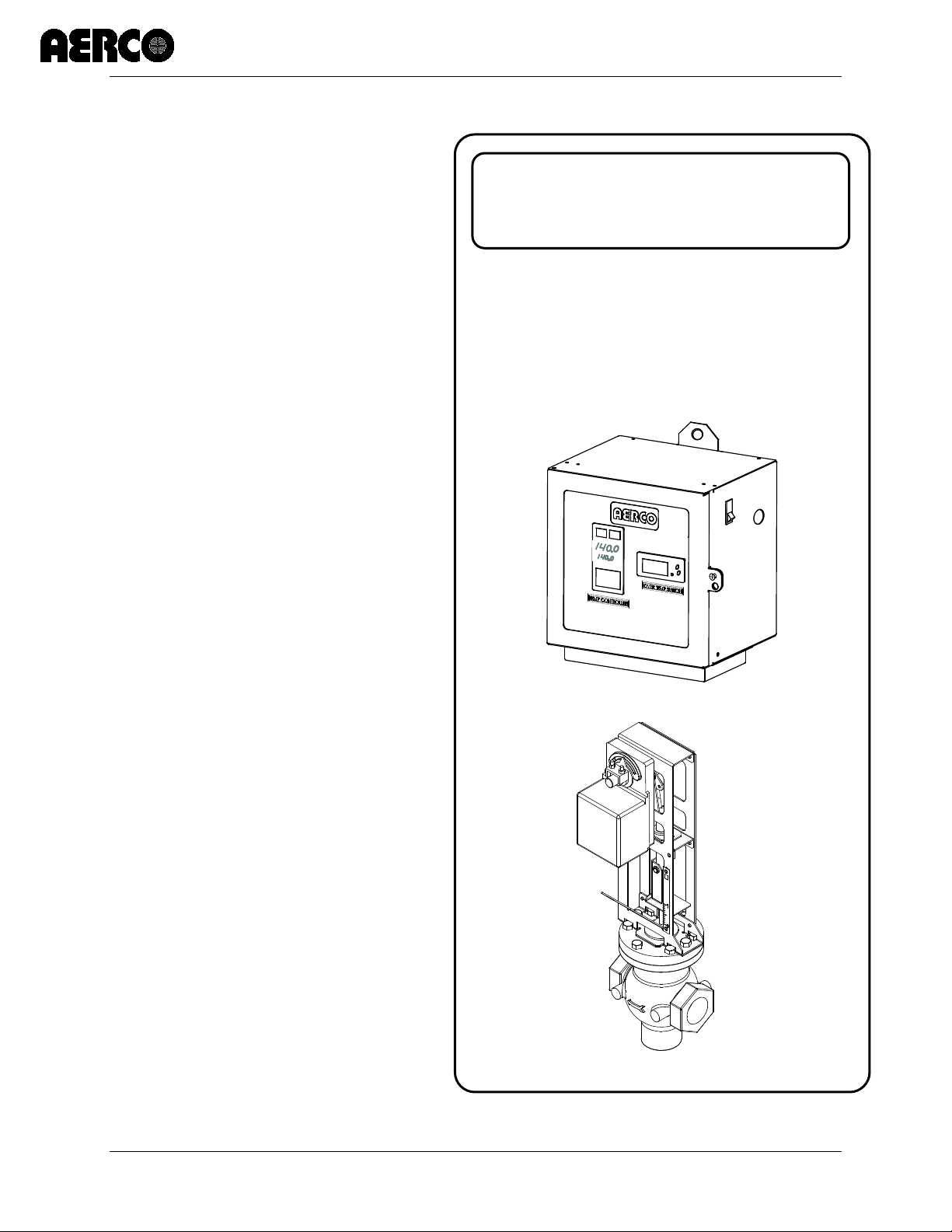
Electronic Control System (ECS) and Type CXT-E Valve
USER MANUAL
Revised: 02/28/2014
Electronic Control
Electronic Control System
Installation, Operation, and Maintenance
Type CXT-E Electronic Valve
User Manual
System (ECS) and
Type CXT-E
Electronic Valve
VD2: 02/28/14 AERCO International, Inc. • 100 Oritani Dr. • Blauvelt, New York 10913 • Phone: 800-526-0288 Page 1 of 82
AC-105 OMM-0003_0D
Page 2

Electronic Control System (ECS) and Type CXT-E Valve
Technical Support:
1-800-526-0288
www.aerco.com
User Manual
(Mon–Fri, 8am-5pm EST)
Disclaimer
The information containe d in this manual is subject to c hange without notice from AERCO Inter national,
Inc. AERCO makes no warranty of any kind with respect to this material, including but not limited to
implied warranties of merchantability and fitness f or a particular application. AE RCO International is not
liable for errors appearing in this manual. Nor for incidental or consequential damages occurring in
connection with the furnishing, performance, or use of this material.
Page 2 of 82 AERCO International, Inc. • 100 Oritani Dr. • Blauvelt, New York 10913 • Phone: 800-526-0288 VD2: 02/28/14
OMM-0003_0D AC-105
Page 3

Electronic Control System (ECS) and Type CXT-E Valve
TABLE OF CONTENTS
TABLE OF CONTENTS
TABLE OF CONTENTS.................................................................................................. 3
SAFETY PRECAUTIONS ............................................................................................... 5
1. GENERAL INFORMATION ..................................................................................... 7
1.1 INTRODUCTION ................................................................................................................... 7
1.2 ELECTRONIC CONTROL SYSTEM (ECS) ................................................................................. 7
1.2.1 Control Box Assembly............................................................................................................................. 9
1.2.2 Feed-Forward Flow Sensor ................................................................................................................... 11
1.2.3 Outlet Temperature Sensors ................................................................................................................ 11
1.2.4 Heating Fluid Inlet/Outlet Temperature Sensors ................................................................................. 11
1.2.5 Over-Temperature Solenoid Valve ....................................................................................................... 11
1.3 ELECTRONIC CONTROL VALVE CXT-E................................................................................. 12
1.3.1 Control Valve Accessories .................................................................................................................... 12
1.4 REFERENCE DOCUMENTS.................................................................................................. 14
1.4.1 AERCO Documents ............................................................................................................................... 14
1.4.2 Eurotherm Documents – (Available at www.eurotherm.com) ............................................................ 14
2. INSTALLATION ..................................................................................................... 15
2.1 INTRODUCTION ................................................................................................................. 15
2.2 ELECTRONIC CONTROL VALVE TYPE CXT-E INSTALLATION ................................................ 15
2.3 ELECTRONIC CONTROL SYSTEM (ECS) INSTALLATION ....................................................... 17
2.4 CHANGING COMMUNICATION ADDRESSES ON AERCO EUROTHERM TEMPERATURE
CONTROLLER ............................................................................................................................. 21
2.5 ENABLING REMOTE SETPOINT CONFIGURATION ON THE AERCO EUROTHERM
TEMPERATURE CONTROLLER .................................................................................................... 24
3. ADJUSTMENT ...................................................................................................... 25
3.1 INTRODUCTION ................................................................................................................. 25
3.2 CONTROL VALVE TYPE CXT-E ADJUSTMENT ...................................................................... 25
3.3 ELECTRONIC CONTROL SYSTEM (ECS) ADJUSTMENT ........................................................ 27
3.3.1 Setpoint Temperature Adjustment ...................................................................................................... 28
3.3.2 Over-Temperature Alarm Limit Adjustment ........................................................................................ 29
3.3.3 Over-Temperature Switch Sensor Adjustment ..................................................................................... 30
4. OPERATION .......................................................................................................... 31
4.1 INTRODUCTION ................................................................................................................. 31
4.2 PRE-OPERATIONAL CHECKS .............................................................................................. 31
4.3 INITIAL START-UP .............................................................................................................. 31
4.4 CHECKING WATER HEATER FLOW RATE ............................................................................ 32
4.5 CHECKING THE VALVE POSITION OUTPUT IN AUTO MODE ............................................... 32
5. FUNCTIONAL DESCRIPTION .............................................................................. 33
5.1 INTRODUCTION ................................................................................................................. 33
5.2 FUNCTIONAL OVERVIEW ................................................................................................... 33
5.3 OVER-TEMPERATURE CONTROL AND SAFETY FEATURES ................................................. 33
6. ROUTINE MAINTENANCE ................................................................................... 35
6.1 INTRODUCTION ................................................................................................................. 35
6.2 CXT-E CONTROL VALVE ROUTINE MAINTENANCE ............................................................ 35
VD2: 02/28/14 AERCO International, Inc. • 100 Oritani Dr. • Blauvelt, New York 10913 • Phone: 800-526-0288 Page 3 of 82
AC-105 OMM-0003_0D
Page 4

Electronic Control System (ECS) and Type CXT-E Valve
TABLE OF CONTENTS
6.2.1 Monthly Maintenance ......................................................................................................................... 35
6.2.2 Semi-Annual Maintenance: .................................................................................................................. 35
6.3 ELECTRONIC CONTROL SYSTEM (ECS) ROUTINE MAINTENANCE ...................................... 36
6.3.1 Quarterly Maintenance: ....................................................................................................................... 36
6.3.2 Annually: .............................................................................................................................................. 36
6.3.3 Temperature Sensors: .......................................................................................................................... 36
6.3.4 Flow Sensor: ......................................................................................................................................... 37
6.4 HEAT EXCHANGER ROUTINE MAINTENANCE CLEANING .................................................. 38
6.4.1 Pumping System Set-Up Instructions: .................................................................................................. 38
6.4.2 Cleaning Procedure: ............................................................................................................................. 39
6.4.3 Testing HydroSkrub Effectiveness ........................................................................................................ 40
6.4.4 Calcium Carbonate Spot Test: .............................................................................................................. 40
6.4.5 pH Trend Charting: ............................................................................................................................... 40
7. TROUBLESHOOTING ........................................................................................... 41
7.1 INTRODUCTION ................................................................................................................. 41
7.1.1 Electronic Control System (ECS) Preliminary Check: ............................................................................. 41
7.1.2 Electronic Control Valve, CXT-E Preliminary Check: ............................................................................. 41
7.2 TROUBLESHOOTING PROCEDURES ................................................................................... 41
8. CORRECTIVE MAINTENANCE ............................................................................ 47
8.1 INTRODUCTION ................................................................................................................. 47
8.2 PART 1 - CXT-E CONTROL VALVE CORRECTIVE MAINTENANCE ......................................... 47
8.2.1 Valve Shaft Seal Retainer Replacement: .............................................................................................. 47
8.2.2 Valve Disassembly ................................................................................................................................ 48
8.2.3 Valve Reassembly ................................................................................................................................ 50
8.2.4 Actuator Replacement ......................................................................................................................... 58
8.2.5 Linkage Assembly Replacement ........................................................................................................... 59
8.3 PART 2 - ECS CORRECTIVE MAINTENANCE ........................................................................ 61
8.3.1 Control Box Assembly and Components .............................................................................................. 61
8.3.2 Control Box Assembly Replacement ..................................................................................................... 62
8.3.3 Temperature Controller Replacement ................................................................................................. 62
8.3.4 Over-Temperature Switch and Temperature Indicator Replacement .................................................. 63
8.3.5 DC Power Supply Replacement ............................................................................................................ 64
8.3.6 DC Voltage Regulator Replacement ..................................................................................................... 65
9. RECOMMENDED SPARE PARTS ........................................................................ 73
9.1 CXT-E CONTROL VALVE RECOMMENDED SPARE PARTS ................................................... 73
9.2 ELECTRONIC CONTROL SYSTEM RECOMMENDED SPARE PARTS ...................................... 73
APPENDIX A ................................................................................................................ 75
9.3 PROCESS ALARMS: ............................................................................................................ 76
9.4 EUROTHERM 2408 PROCESS ALARMS ........................................................................................ 76
9.5 DIAGNOSTIC ALARMS ........................................................................................................ 76
9.6 EUROTHERM 2408 DIAGNOSTIC ALARMS ................................................................................... 76
9.6.1 Clearing Hardware Error (Hw.Er) Display............................................................................................. 77
APPENDIX B ................................................................................................................ 79
Page 4 of 82 AERCO International, Inc. • 100 Oritani Dr. • Blauvelt, New York 10913 • Phone: 800-526-0288 VD2: 02/28/14
OMM-0003_0D AC-105
Page 5
Electronic Control System (ECS) and Type CXT-E Valve
! ! !
!
SAFETY PRECAUTIONS
SAFETY PRECAUTIONS
Installing or operating personnel must, at all times, observe all saf ety regulat ions. The following
warnings are general and must be given the same attention as specific precautions included in
the instructions.
WARNING
FLUIDS UNDER PRESSURE MAY CAUSE INJURY TO
PERSONNEL OR DAMAGE TO EQUIPMENT WHEN RELEASED.
CLOSE ALL SHUTOFF VALVES AND CAREFULLY DECREASE
ALL TRAPPED PRESSURES TO ZERO BEFORE PERFORMING
ANY MAINTENANCE. TAG THE PRESSURE SOURCE “OUT OF
SERVICE” WHILE PERFORMING MAINTENANCE TASKS.
WARNING
LIVE STEAM CAN CAUSE SEVERE BURNS.
NEVER SEARCH FOR LEAKAGE IN A LIVE STEAM LINE BY
SIGHT ALONE OR BY “FEEL.” USE A MIRROR OR OTHER
SUITIBLE POLISHED OBJECT. ALSO, ALW AYS WEAR GLOVES
AND LONG SLEEVES.
VD2: 02/28/14 AERCO International, Inc. • 100 Oritani Dr. • Blauvelt, New York 10913 • Phone: 800-526-0288 Page 5 of 82
AC-105 OMM-0003_0D
Page 6

Electronic Control System (ECS) and Type CXT-E Valve
SAFETY PRECAUTIONS
(This page intentionally blank)
Page 6 of 82 AERCO International, Inc. • 100 Oritani Dr. • Blauvelt, New York 10913 • Phone: 800-526-0288 VD2: 02/28/14
OMM-0003_0D AC-105
Page 7

Electronic Control System (ECS) and Type CXT-E Valve
1. GENERAL INFORMATION
1. GENERAL INFORMATION
1.1 INTRODUCTION
This Instruction Manual provides detailed coverage for both the AERCO Electronic Control
System (ECS) and the Electronic Control Valve CXT-E. This Control System and Valve
combination can be used with all models and sizes of AERCO Indirect Fired Water Heaters
which include the following Models:
• SW1A PLUS,
• SW1B PLUS, SW1B PLUS II,
• WW3E PLUS
Double- W all Heater Models DW-24, DW -45, DW-68 (Refer to HE-111 for SWDW-24 , S W DW45 & SWDW-68 Models)
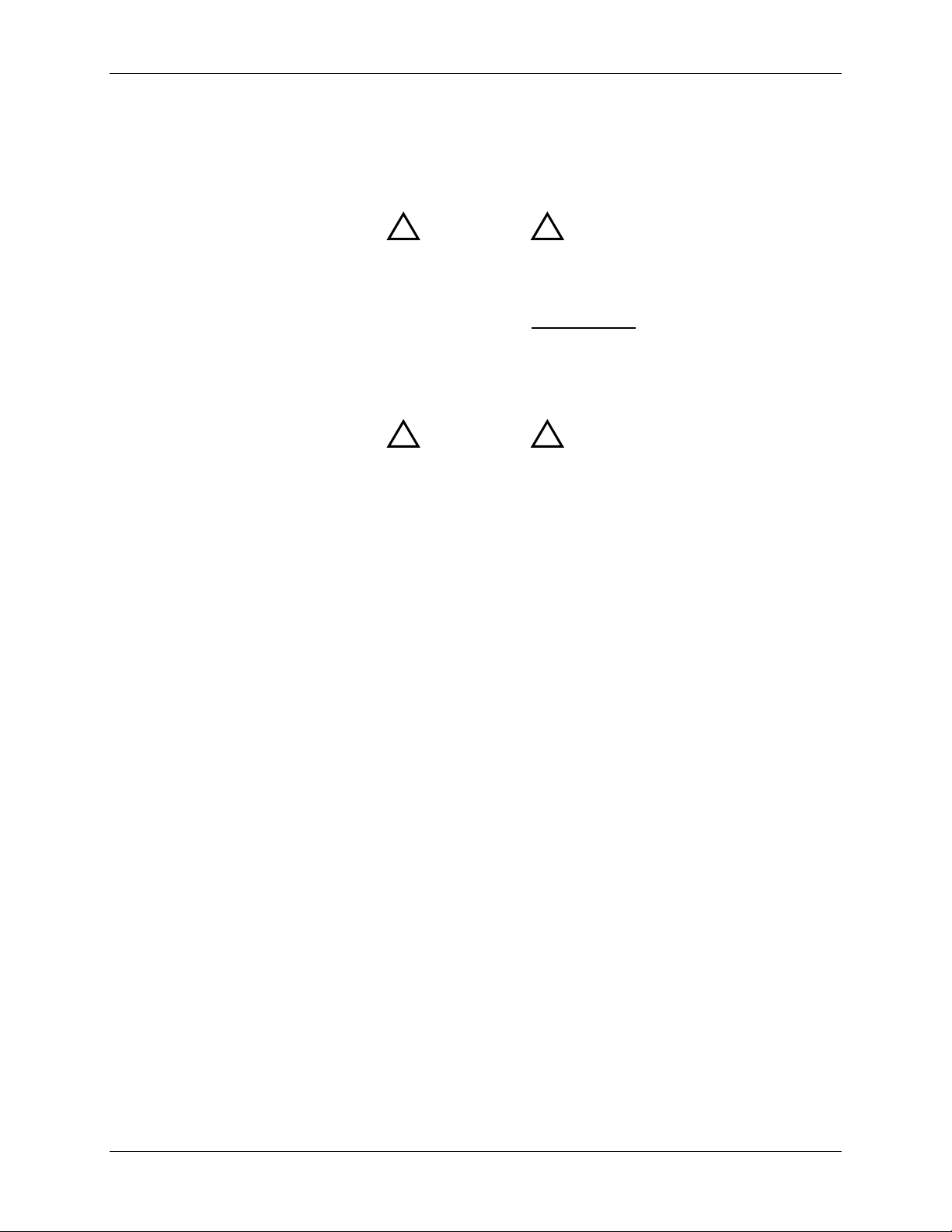
Figure 1-1 shows a typical installation with a Water Wizard, Model SW1B-Plus II Packaged
Water Heater. The remaining paragraphs in this section provide descriptions of the units,
assemblies and sub-assemblies included with the Electronic Control System (ECS) and the
Electronic Control Valve CXT-E.
NOTE:
This Instruction Manual provides detailed Installation, Operation,
Maintenance and Parts information and procedures for the Electronic
Control System and Electronic Control Valve. A separate Instruction
Manual for the Heat Exchanger is included with the Packaged W ater
Heater. Also, refer to the paragraph titled REFERENCE
DOCUMENTS at the end of this Section for additional documentation
which may be required for accessories or options provided with your
order.
1.2 ELECTRONIC CONTROL SYSTEM (ECS )
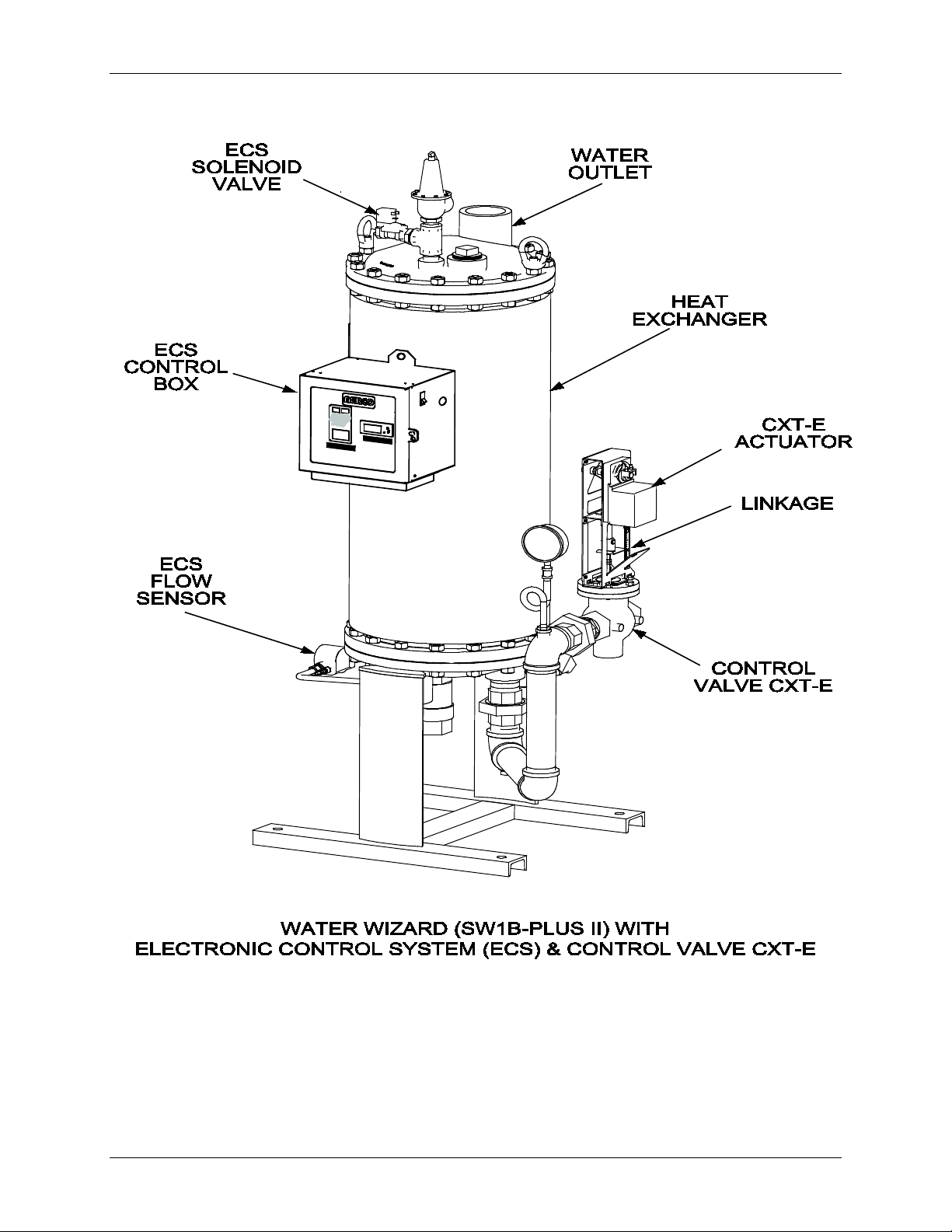
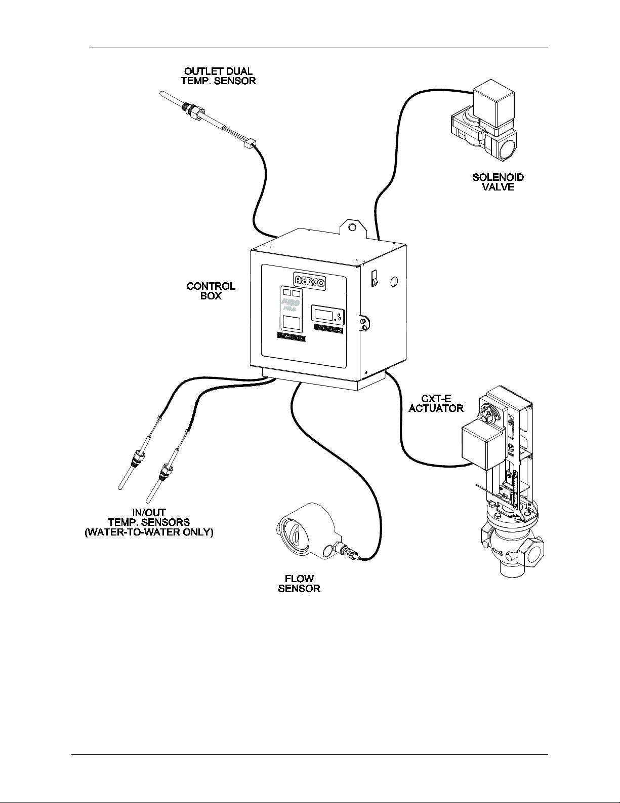
The Electronic Control System contains a Control Box Assembly which includes all of the
electronic circuitry for the ECS. In addition, the ECS includes several sensors and safety
devices which provide temperature and flow control information to the Control Box circuitry. The
Control Box and the additional devices included in the ECS are shown in Figure 1-2. The
additional devices included in the ECS include:
• Feed-Forward Flow Sensor (Flowmeter)
• Outlet Dual Temperature Sensors (Type J Thermocouples)
• Heating Fluid Inlet/Outlet Temperature Sensors (Type J Thermocouples) – For Water-to-
Water Heat Exchangers Only
• Over-Temperature Solenoid Valve
If desired, the Electronic Control System (ECS) can be ordered with a Modbus Communication
Option. This option permits the ECS to be externally controlled by an Energy Management
System (EMS), Building Automation System (BAS), or Computer supplied by other
manufacturers.
A Gateway option exists to link with other communication protocols. Check with your AERCO
sales representative for more information.
The Electronic Control System assemblies and components are described in the following
paragraphs.
VD2: 02/28/14 AERCO International, Inc. • 100 Oritani Dr. • Blauvelt, New York 10913 • Phone: 800-526-0288 Page 7 of 82
AC-105 OMM-0003_0D
Page 8
Electronic Control System (ECS) and Type CXT-E Valve
1. GENERAL INFORMATION
Figure 1-1. Typical ECS & CXT-E Installation With a Packaged Water Heater
Page 8 of 82 AERCO International, Inc. • 100 Oritani Dr. • Blauvelt, New York 10913 • Phone: 800-526-0288 VD2: 02/28/14
OMM-0003_0D AC-105
Page 9
Electronic Control System (ECS) and Type CXT-E Valve
1. GENERAL INFORMATION
Figure 1-2. Electronic Control System (ECS)
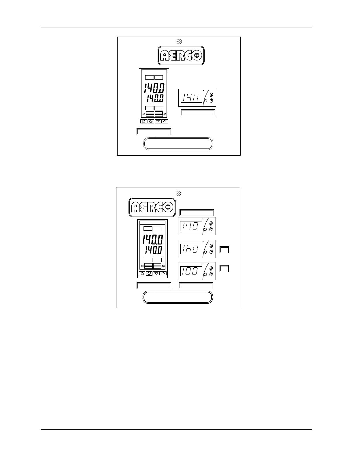
1.2.1 Control Box Assembly
The Control Box Assembly is available in two models; one for Steam-to-Water Heaters and one
for Water-to-Water Heaters. The only difference between these two models are the Display
devices provided on the front panels. The panel of the Control Box model for W ater -to-Water
applications contain two additional Display devices which display the heating fluid (hot boiler
water) inlet and outlet temperatures. The Control Box front panels for both models are shown in
Figure 1-3.
VD2: 02/28/14 AERCO International, Inc. • 100 Oritani Dr. • Blauvelt, New York 10913 • Phone: 800-526-0288 Page 9 of 82
AC-105 OMM-0003_0D
Page 10
Electronic Control System (ECS) and Type CXT-E Valve
MODEL 69012-1
FRONT PANEL FOR STEAM-TO-WATER HEATERS
B-PLUS
TM
PT.NO.
SET
F
AUTO
RUN
MAN HOLD
OP 1
OP 2
SP2
REM
2408
OVER TEMP SWITCH
TEMP CONTROLLER
PT.NO.
WATER HEATER
MODEL 69012-2
FRONT PANEL FOR WATER-TO-WATER HEATERS
SET
F
SET
F
SET
F
AUTO
RUN
MAN HOLD
OP 1
OP 2
SP2
REM
2408
PT.NO.
OVER TEMP SWITCH
BOILER WATER TEMPTEMP CONTROLLER
E-PLUS
WATER HEATER
TM
PT.NO.
OUT
IN
1. GENERAL INFORMATION
Figure 1-3. ECS Control Box Models Showing Front Panel Differences
The Control Box is the heart of the ECS. It contains the Temperature Controller, an OverTemperature Switch and, when required, Inlet/Outlet Temperature Indicators for Water-to-Water
applications. The Temperature Controller is the “brain” of the ECS which processes data
received from the temperature and flow sensors. Using PID (Proportional Integral Derivative)
algorithms, the Temperature Controller provides a 4-to-20 mA control signal to the Control Valve
Actuator which precisely modulates the Control Valve for optimum outlet temperature control.
Page 10 of 82 AERCO International, Inc. • 100 Oritani Dr. • Blauvelt, New York 10913 • Phone: 800-526-0288 VD2: 02/28/14
OMM-0003_0D AC-105
Page 11

Electronic Control System (ECS) and Type CXT-E Valve
1. GENERAL INFORMATION
An Over-Temperature Switch is also included in the Control Box to constantly monitor the Water
Heater outlet temperature to ensure the Heater does not exceed the preset high temperature
limit. Typically, the over-temperature limit is set 20°F above the desired Heater setpoint
temperature. If an over-temperature condition occurs, this Switch sounds an audible alarm,
activates the Over-Temperature Solenoid and cuts off power to the Control Valve Actuator. This
closes the Control Valve and shuts off the heating fluid (steam or hot boiler water) to the Heat er.
In addition, activation of the Over-Temperature Solenoid allows over-temperature water to be
dumped from the Heater shell.
The Control Box also contains a DC Power Supply and Voltage Regulator to provide the voltag e
levels required by the ECS Control Box circuitry, flow sensor and safety devices. It also provides
24 VDC power to the Control Valve CXT-E Actuator.
The Control Box components are housed in a steel enclosure with a hinged front door. This
door contains a clear polycarbonate window which permits maintenance personnel to view the
controls and displays of the Temperature Controller, and other display devices mounted on a
recessed panel behind the door. All sensor and control signal connections are made via cable
connections at the bottom of the Control Box. External AC power (120 to 240 VAC, 50/60 Hz) is
supplied via a cutout on the right side of the Control Box.
1.2.2 Feed-Forward Flow Sensor
The Feed-Forward Flow Sensor is installed between the cold water inlet and the drain valve on
the Water Heater as shown in Figure 1-1. The Flow Sensor monitors a portion of the inlet flow to
the Heater and provides a feed-forward signal to the Temperature Controller which is
proportional to the change in flow through the Heater.
1.2.3 Outlet Temperature Sensors
The Control System includes a Dual Temperature Sensor which is installed in the hot water
outlet of the Water Heater. This sensor contains two identical Type J thermocouples. The first
thermocouple connects directly to the Temperature Controller in the Control Box to provide the
outlet water temperature. The second thermocouple connects to the Over-Temperature Switch
in the Control Box.
1.2.4 Heating Fluid Inlet/Outlet Temperature Sensors
When the Heater utilizes hot (boiler) water as the heating fluid, two additional Temperature
Sensors (Type J thermocouples) are provided with the Control System. One temperature
Sensor is installed at the heating fluid inlet and t he other is installed at the heating fluid outlet.
These two Sensors are connected to two identical Temperature Display Indicators in the Control
Box to provide real-time indications of the inlet and outlet heating fluid temperatures. These
Temperature Indicators are physically identical to the Over-Temperature Switch, however they
are “Indicator-Only” devices and do not provide any switching functions.
1.2.5 Over-Temperature Solenoid Valve
As previously mentioned, the Over-Temperature Solenoid Valve operates in conjunction with
the Over-Temperature Switch in the Control Box. An over-temperature alarm is activated when
the preset high temperature limit is exceeded, thereby energizing and opening the Solenoid
Valve. This allows over-heated water and pressure build-up to be expelled from the Heater Shell
and relieve pressure build-up.
VD2: 02/28/14 AERCO International, Inc. • 100 Oritani Dr. • Blauvelt, New York 10913 • Phone: 800-526-0288 Page 11 of 82
AC-105 OMM-0003_0D
Page 12

Electronic Control System (ECS) and Type CXT-E Valve
ACCESSORY
REQUIREMENT
•
- Mandatory
•
Suggested for ease of
maintenance. Required if a
•
Mandatory
•
Recommended for adjustment
• Low Side Pressure Gauge,
Compound Type for steam flow
Recommended for adjustment
1. GENERAL INFORMATION
1.3 ELECTRONIC CONTROL VALVE CXT-E
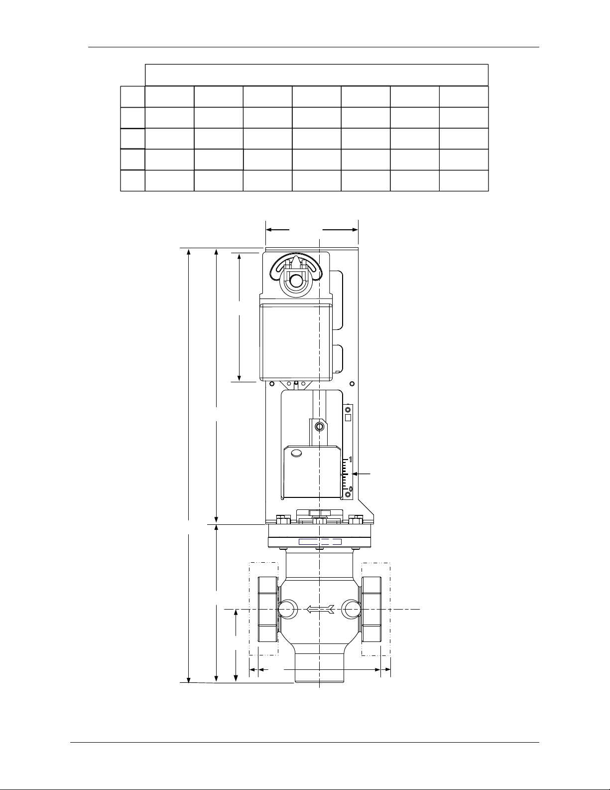
Each Control Valve is comprised of three major sections; the Valve Body, Linkage Assembly
and the Valve Actuator. The Control Valves are available in sizes ranging from 1 inch to 4
inches. An identical Actuator Assembly is used with each size Valve Body. The Linkage
Assembly used with each size Valve Body is identical, except for minor differences in the Shaft
Adapter stroke of the mechanical linkage. Figure 1-4 shows the basic dimensions for each size
AERCO Control Valve CXT-E.
It should be noted that the Control Valves used for steam flow are identical to those used for hot
(boiler) water flow.
1.3.1 Control Valve Accessories
The accessories required for use with AERCO Electronic Control Valves, Type CXT-E will
depend on the specific application. Detailed installation instructions, including typical installation
drawings are provided in the INSTALLATION Section of this manual. However, please note the
items listed below and ensure that ALL mandatory items are available:
Upstream Shutoff Valve
Downstream Shutoff Valve
Bypass Line is used.
Strainer and Blow-Off Valve
High Side Pressure Gauge
and maintenance
and maintenance.
If any of these items have been furnished by AERCO with the Control Valve, the
necessary drawings and/or instructions should be included with the shipment.
Page 12 of 82 AERCO International, Inc. • 100 Oritani Dr. • Blauvelt, New York 10913 • Phone: 800-526-0288 VD2: 02/28/14
OMM-0003_0D AC-105
Page 13
Electronic Control System (ECS) and Type CXT-E Valve
A
B
C
D
13.375
6.60"
4.50"
DIM. 1.00"
1.25" 1.50" 2.00" 2.50" 3.00" 4.00"
A
B
C
D
21.12 21.12 21.12 24.25 24.25
24.25
24.25
7.75 7.75
7.75
7.75 10.87 10.87 10.87
3.56
3.56
3.56 3.56 6.38 6.38 6.38
6.00
6.00 6.00 6.00 10.87 10.87 10.87
VALVE SIZES (INCHES)
POSITION
SCALE
1. GENERAL INFORMATION
Figure 1-4. Reference Dimensions for AERCO Control Valves, Type CXT-E
VD2: 02/28/14 AERCO International, Inc. • 100 Oritani Dr. • Blauvelt, New York 10913 • Phone: 800-526-0288 Page 13 of 82
AC-105 OMM-0003_0D
Page 14

Electronic Control System (ECS) and Type CXT-E Valve
HE-104
SW1B-Plus Heat Exchanger Installation, Operation & Maintenance Manual
HE-105
WW3E Heat Exchanger Installation, Operation & Maintenance Manual
HE-106
DW-24, DW-45, DW-68 Double Wall Heat Exchanger Installation, Operation &
Maintenance Manual
HE-107
SW1A-Plus Heat Exchanger Installation, Operation & Maintenance Manual
HE-110
B-Plus II Water Wizard Heat Exchanger Installation, Operation & Maintenance
Manual
HA025132
2404/2408 Installation & Operation Handbook
HA02630
Series 2000 Communications Handbook
!
!
1. GENERAL INFORMATION
1.4 REFERENCE DOCUMENTS
Refer to the following documents as necessary for additional information and procedures for the
applicable AERCO Heat Exchanger provided with your Electronic Control System (ECS) and CXT-E
Control Valve. In addition, if the ECS is provided with the Modbus Com munication option, refer to the
referenced Eurotherm documents listed.
1.4.1 AERCO Documents
1.4.2 Eurotherm Documents – (Available at www.eur ot herm.com)
CAUTION
DO NOT use the Actuator Linkage Frame at the top of the Control
Valve Body for leverage when installing The Control Valve. Use pipe
wrenches on the inlet and outlet hex of the Valve Body.
Page 14 of 82 AERCO International, Inc. • 100 Oritani Dr. • Blauvelt, New York 10913 • Phone: 800-526-0288 VD2: 02/28/14
OMM-0003_0D AC-105
Page 15
Electronic Control System (ECS) and Type CXT-E Valve
2. INSTALLATION
2. INSTALLATION
2.1 INTRODUCTION
Normally, the Electronic Control System (ECS) is shipped already installed on the Packaged
Water Heater. However, the Control Valve, Type CXT-E is packed separately. For smaller size
Valves (1” to 2”), the packaged Valve is attached to the base of the shipping crate. For larger
size Valves (2 ½” to 4”), the packaged Valve may be shipped separately due to space
limitations within the Heater shipping crate. Therefore, the installation procedures consist
basically of:
• Installing the Electronic Control Valve, Type CXT-E and associated steam or hot (boiler)
water piping and components.
• Connecting external power to the ECS Control Box
• Connecting and checking electrical connections to the CXT-E Actuator and other ECS
components
IMPORTANT NOTE!
For Water-to-Wat er Doub le -Wall (WWDW) heaters equipped with the
ECS, the following minimum recirculation flow must be provided to
achieve ±4°F temperature control under normal diversified domestic
load conditions:
Double-Wall Model Minimum System Recirculation
WWDW24 10 gpm
WWDW45 15 gpm
WWDW68 20 gpm
2.2 ELECTRONIC CONTROL VALVE TYPE CX T-E INSTALLATION
The following procedures apply to all sizes of AERCO Electronic Control Valves Type CXT-E
ranging from 1 inch to 4 inches. In addition, the following steps can be us ed for both st eam and
hot (boiler) water flow systems. Proceed as follows:
1) Refer to Figure 1-3 for dimensions of the Control Valve furnished with the Packaged W ater
Heater.
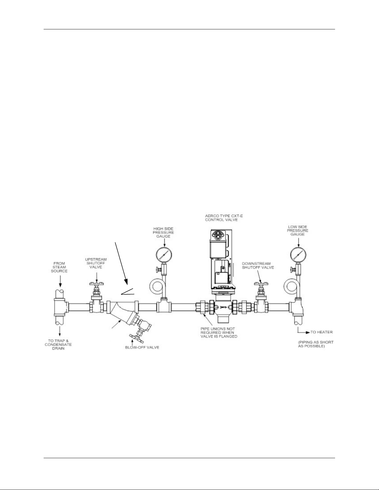
2) Next, refer to the recommended installation drawing in Figure 2-1 for steam flow, or Figure
2-2 for hot (boiler) water flow.
3) Install the Control Valve with the Actuator Linkage in the vertical, upright position as shown
in Figure 2-1 or 2-2.
4) For maintenance purposes, unions are required with threaded ends to simplify removal
from the steam or hot boiler water line.
5) Blow out all pipe lines to clear them of dirt chips, scale or other foreign matter which could
adversely affect Valve operation when in service.
6) Install an in-line strainer upstream of the Valve as shown in Figure 2-1 (steam) or Figure 22 (hot boiler water). This will protect against foreign matter reaching the Valve during
service operation.
VD2: 02/28/14 AERCO International, Inc. • 100 Oritani Dr. • Blauvelt, New York 10913 • Phone: 800-526-0288 Page 15 of 82
AC-105 OMM-0003_0D
Page 16
Electronic Control System (ECS) and Type CXT-E Valve
STRAINER WITH 0.020
FOR CLARITY
PIPING PITCH DIRECTION
1 TO 40 RATIO MINIMUM
2. INSTALLATION
7) If the Valve is controlling steam, ensure that the steam line is pr operly trapped to prevent
accumulation of condensate ahead of the Valve.
8) Install Shutoff Valves (metal-seated, g ate-type) upstream and downstream of the Control
Valve to permit removal from the line for maintenance.
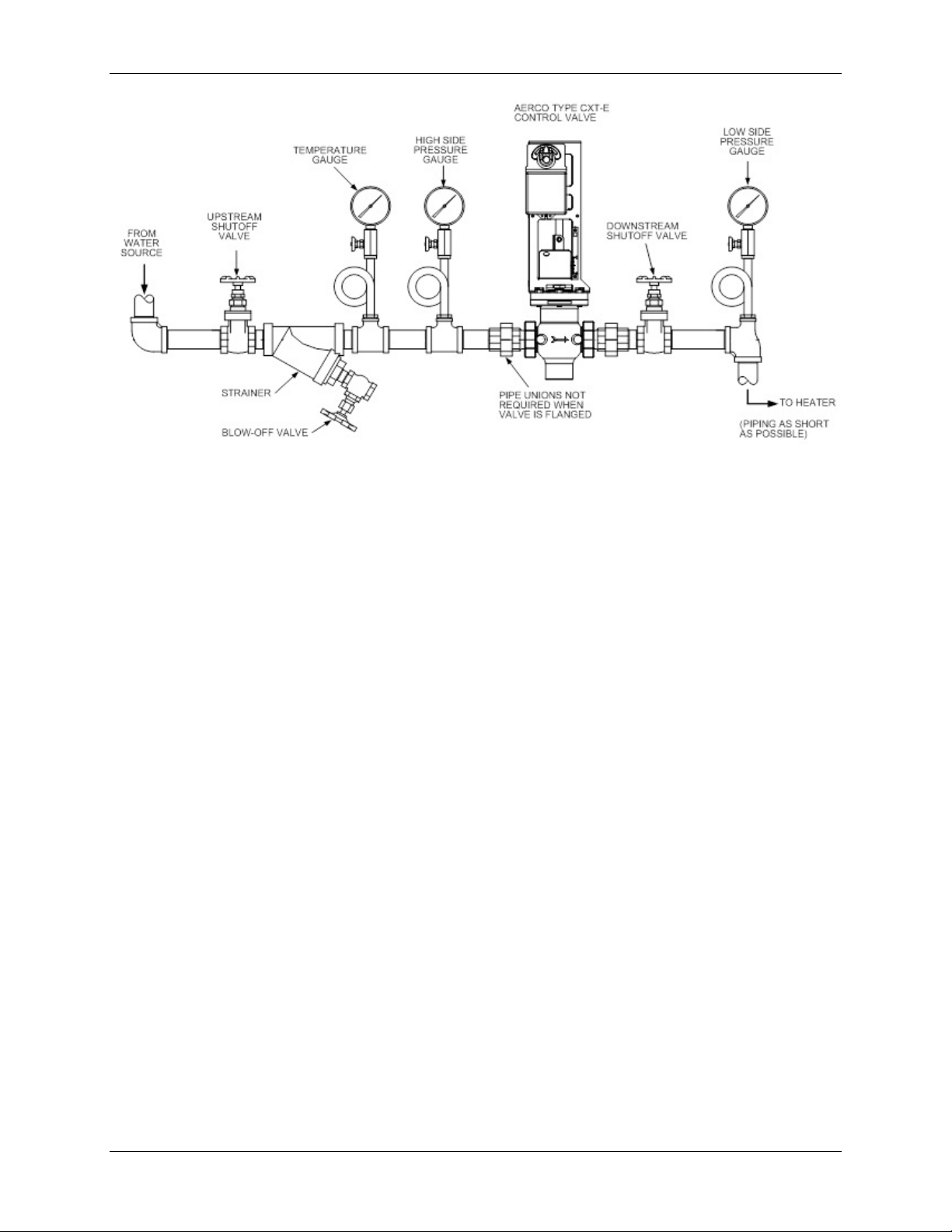
9) Pressure gauges should be installed on both sides of the Control Valve as shown in Figure
2-1 (steam) or Figure 2-2 (hot water).
10) The gauge on the high pressure side of the Valve is for adjustment and maintenance
purposes. The gauge on the low pressure side is to ensure that the correct pressure is
being introduced to the Control Valve. For either steam or water flow, the low side gauge
denotes the pressure of the fluid in the line which may create a hazardous condition.
11) A temperature gauge should be installed in the high pressure side of a hot (boiler) water
line as shown in Figure 2-2.
12) Install the Control Valve with the arrow on the Valve Body pointing in the direction of flow.
13) After the Control Valve has been installed in the steam or hot water line, ensure that all
piping connections are secure and leak tight.
14) This completes the installation procedures for the Control Valve. Proceed to the next
paragraph titled ELECTRONIC CONTROL SYSTEM INSTALLATION.
Figure 2-1. Recommended Control Valve, CXT-E Installation For Steam Flow
Page 16 of 82 AERCO International, Inc. • 100 Oritani Dr. • Blauvelt, New York 10913 • Phone: 800-526-0288 VD2: 02/28/14
OMM-0003_0D AC-105
MEST STAINLESS
STEEL BASKET,
SHOWN ROTATED
DOWN 90 DEGREES
Page 17
Electronic Control System (ECS) and Type CXT-E Valve
2. INSTALLATION
Figure 2-2. Recommended Control Valve, CXT-E Installation For Hot (Boiler)
Water Flow
2.3 ELECTRONIC CONTROL SYSTEM (ECS ) INSTALLATION
As previously mentioned, the Control Box and all other Electronic Control System (ECS)
components are installed on the Packaged Water Heater prior to shipment from the factory.
Therefore, ECS installation basically consists of connecting external AC power to the System
and providing the necessary power and control signal connections to the Control Valve Type
CXT-E. However, if your ECS was ordered with the Modbus Communication option, several
additional signal lead connections will need to be made inside the Control Box. These signal
leads will permit the ECS to be controlled by an external Energy Management System (EMS),
Building Automation System (BAS), or Computer.
NOTE:
Following installation, a lock (Not Supplied) can be installed on the
front door of the Control Box, if desired, to prevent unauthorized
access to ECS settings.
VD2: 02/28/14 AERCO International, Inc. • 100 Oritani Dr. • Blauvelt, New York 10913 • Phone: 800-526-0288 Page 17 of 82
AC-105 OMM-0003_0D
Page 18
Electronic Control System (ECS) and Type CXT-E Valve
WATER HEATER
TEMP CONTROLLER
B-PLUS
TM
HOLD
RUN
AUTO
MAN
2408
PT.NO.
PT.NO.
OVER TEMP SWITCH
PANEL
DOOR
CAPTIVE
SCREW
B-PLUS
TM
PT.NO.
SET
F
AUTO
RUN
MAN HOLD
OP 1
OP 2
SP2
REM
2408
OVER TEMP SWITCH
TEMP CONTROLLER
PT.NO.
WATER HEATER
PANEL CAPTIVE
SCREW
2. INSTALLATION
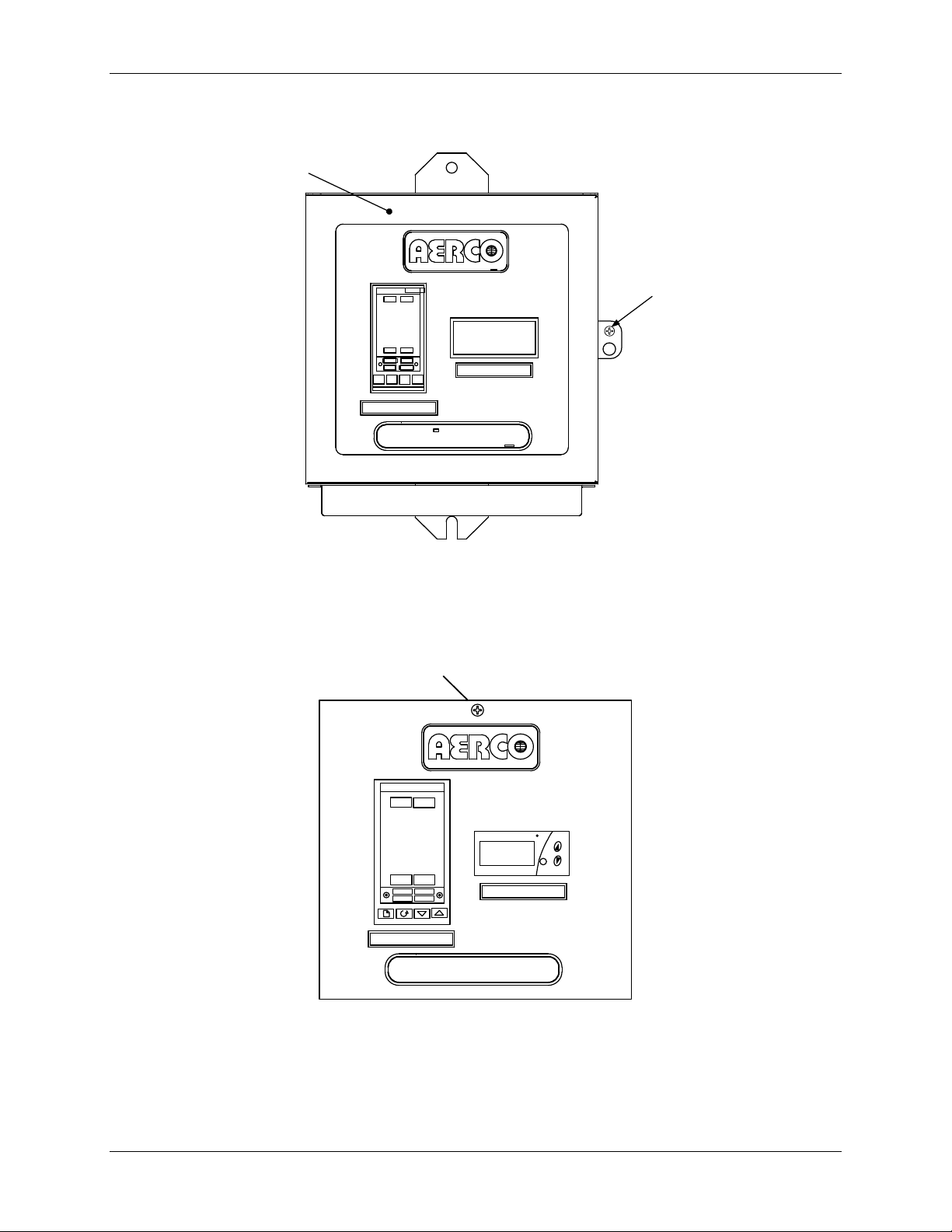
1) Loosen the captive screw on the right-front portion of the Control Box (Figure 2-3) to open
the hinged panel door.
Figure 2-3. ECS Control Panel Front View
2) Next, open the door and loosen the captive screw at the top of the recessed panel (Figure
2-4). Swing down the recessed panel to access Terminal Block TB-2 on the bottom interior
surface of the Control Box shown in Figure 2-5.
3) Feed the external 120/240 VAC power leads through the cutout labeled “POWER IN” on the
right side of the Control Box.
Figure 2-4. Recessed Panel Behind Control Box Door
Page 18 of 82 AERCO International, Inc. • 100 Oritani Dr. • Blauvelt, New York 10913 • Phone: 800-526-0288 VD2: 02/28/14
OMM-0003_0D AC-105
Page 19
Electronic Control System (ECS) and Type CXT-E Valve
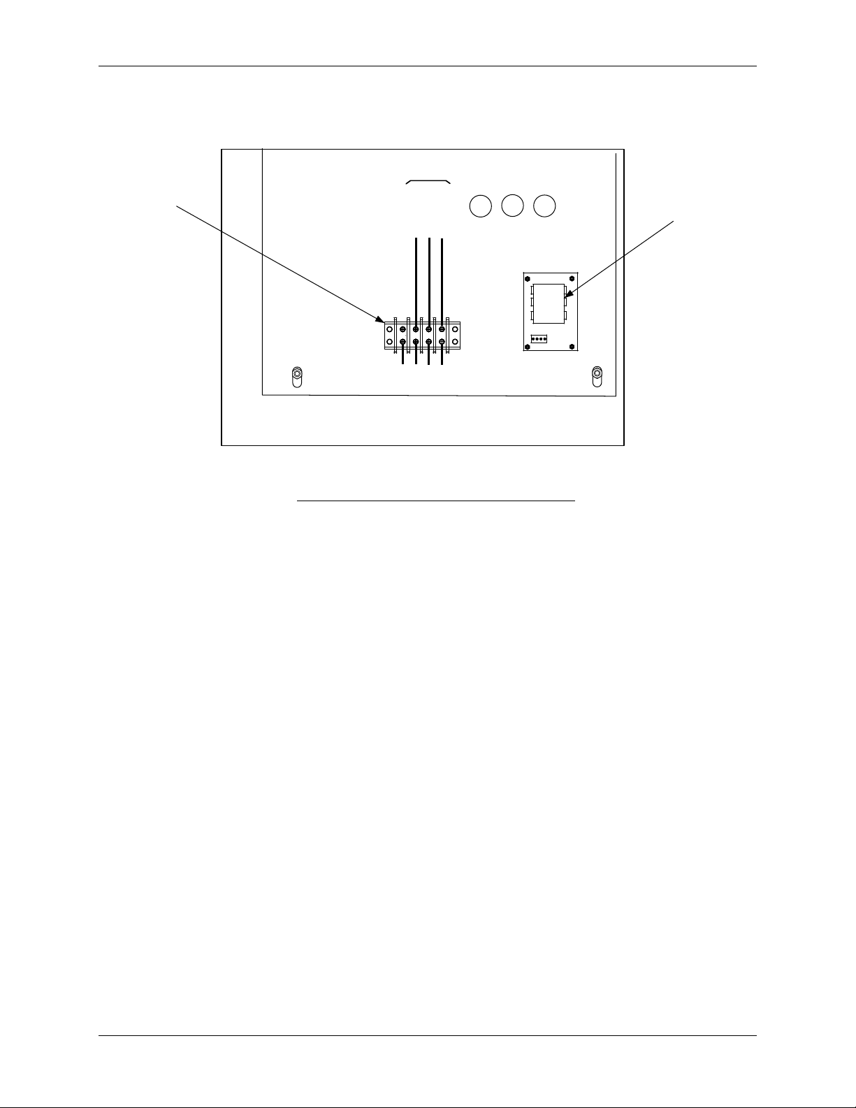
CONTROL BOX - INTERIOR BOTTOM VIEW
REAR
TB-2
LINE
NEUTRAL
GROUND
100
101
102
GND
FRONT
VOLTAGE
REGULATOR
TERMINAL
BLOCK TB-2
EXTERNAL POWER WIRING
(120 – 240 VAC)
2. INSTALLATION
4) Connect the LINE, NEUTRAL and GROUND leads to the TB-2 terminals shown in Figure 2-
5.
Figure 2-5. ECS Control Box AC Power Connections
5) Connect the Control Box cable labeled ACTUATOR to the 3-pin connector plug on the
Control Valve Actuator.
6) Check to ensure that all cable harness connectors and wire leads between the Control Box
and the following ECS components are secure:
a) Flow Sensor
b) Over-Temperature Solenoid
c) Outlet Dual Temperature Sensor
d) Heating Fluid Inlet/Outlet Temperature Sensors (Water-to-Water Heaters Only)
7) If the ECS was ordered with the Modbus Communication Option, proceed to step 8.
However, if this option is not included, no further steps are required for ECS installation.
NOTE:
Step 8 applies ONLY to Electronic Control Systems which include a
Temperature Controller (Eurotherm, Model 2408) equipped with a
Communications Board which allows connection to Modbus
Networks. The required signal connections will depend on the ports
available on the Energy Management System (EMS), Building
Automation System (BAS), or Computer being used with the ECS.
VD2: 02/28/14 AERCO International, Inc. • 100 Oritani Dr. • Blauvelt, New York 10913 • Phone: 800-526-0288 Page 19 of 82
AC-105 OMM-0003_0D
Page 20
Electronic Control System (ECS) and Type CXT-E Valve
COMPUTER CONTROL CABLE
RS232/9-PIN
RS232/25-PIN
RS485
SIGNAL NAME
PIN NO.
SIGNAL NAME
PIN NO.
PIN NO.
PIN NO.
GROUND
HD
GROUND
5
7
GROUND
RECEIVE
HE
TRANSMIT
3
2
A (-)
TRANSMIT
HF
RECEIVE
2
3
B (+)
2. INSTALLATION
CAUTION!
DO NOT route Modbus communication wiring in the same
conduit as power wiring. Attempting to do so may result in
excessive noise on the signal lines. Also, ensure that the RS232
or RS485 signal cable connections do not exceed the following
lengths:
RS232 Cable: 50 feet maximum
RS485 Cable: 4,000 feet maximum
8) To permit Modbus control of the ECS, refer to Table 2-1 and connect the appropriate wire
leads to the Temperature Controller terminals listed. Refer to the Temperature Controller
(Eurotherm 2408) pinouts shown in Figure 2-6 to locate the required terminals. Also, refer
to Appendix A for a listing of active Modbus data addresses for the 2408 Controller. In
addition, the Eurotherm documents referenced in this Appendix provide additional
communication information related to Modbus.
NOTE:
The complete wiring diagram for the Electronic Control System is
provided in Appendix B of this Instruction Manual. In addition, the
wiring connections for Terminal Block s TB-1 and TB-2 are provided
for reference purposes.
AERCO recommends that shielded, twisted-pair cable be used for
communication wiring. Examples of suitable wiring are: Belden 9841,
8761, 3105A, or equivalent.
Table 2-1. Modbus Communication Signal Connections
2408 TEMP. CONTROLLER
NOTE:
Page 20 of 82 AERCO International, Inc. • 100 Oritani Dr. • Blauvelt, New York 10913 • Phone: 800-526-0288 VD2: 02/28/14
OMM-0003_0D AC-105
Page 21
Electronic Control System (ECS) and Type CXT-E Valve
1A
HA
1B
HB
1C
HC
2A
2B
1D
HE
HF
HD
3B
3D
3C
2D
3A
2C
JD
JF
JE
JB
JC
JA
LA
LB
LC
AA
AB
AC
VI
V+
V-
In1
In2
C
2408 CONTROLLER
L
N
SEE TABLE 2-1 FOR COMM CONNECTIONS
Page
Scroll
Down
Arrow
UP
Arrow
2. INSTALLATION
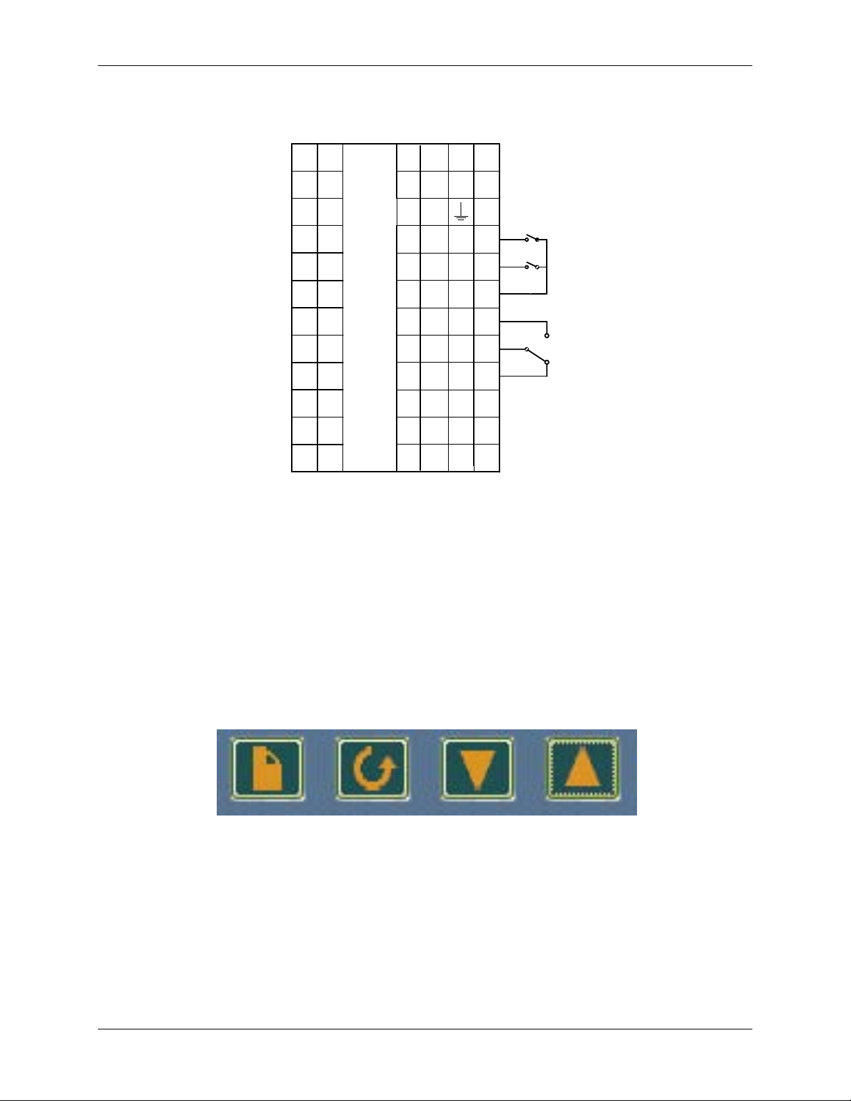
Figure 2-6. Temperature Controller (Eurotherm 2408) Terminal Connection
2.4 CHANGING COMMUNICATION ADDRESS E S O N AERCO EUROTHERM TEMPERATURE CONTROLLER
The address is defaulted t o 1 from the factory. Refer to the Button map below for all panel
navigation instructions.
VD2: 02/28/14 AERCO International, Inc. • 100 Oritani Dr. • Blauvelt, New York 10913 • Phone: 800-526-0288 Page 21 of 82
AC-105 OMM-0003_0D
Diagram
Button Map
Page 22
Electronic Control System (ECS) and Type CXT-E Valve
2. INSTALLATION
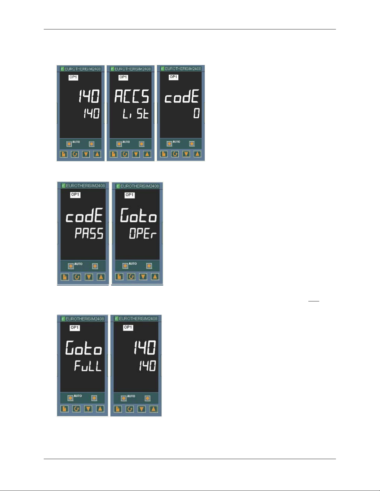
To change the modbus address:
1) Page to the ACCS list and Scroll down the list to codE.
2) Enter 24 using the Up Arrow. The number will display and flash PASS.
3) Scroll to Goto (current value is OPEr) and use the Down Arrow t o enter a value of Full. The
entry is confirmed by the flashing of the lower display momentarily off and then on.
Page 22 of 82 AERCO International, Inc. • 100 Oritani Dr. • Blauvelt, New York 10913 • Phone: 800-526-0288 VD2: 02/28/14
OMM-0003_0D AC-105
Page 23
Electronic Control System (ECS) and Type CXT-E Valve
2. INSTALLATION
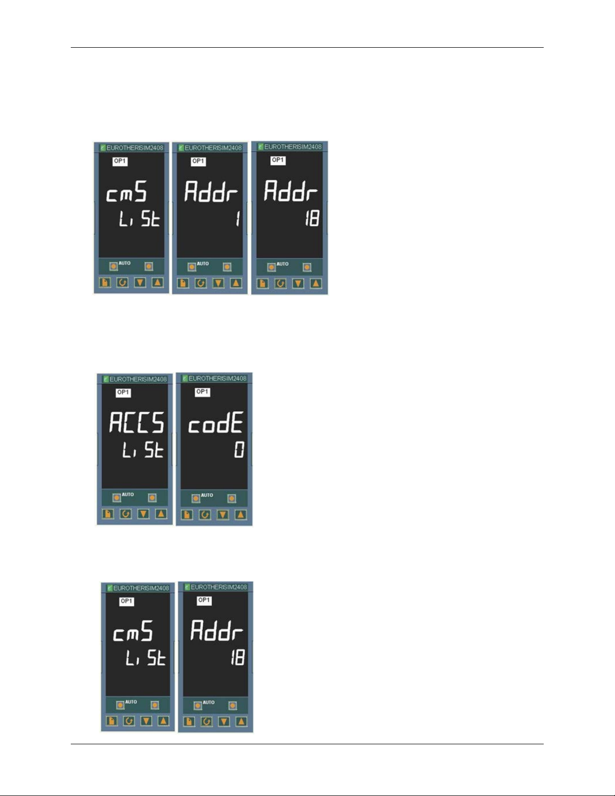
4) Go to the home screen by pressing the Page and Scroll buttons at the same time.
5) Page to the cmS list.
6) Scroll to the Addr screen
7) Use the Up Arrow to select the desired address number.
8) Go to the home screen by pressing the Page and Scroll buttons at the same time.
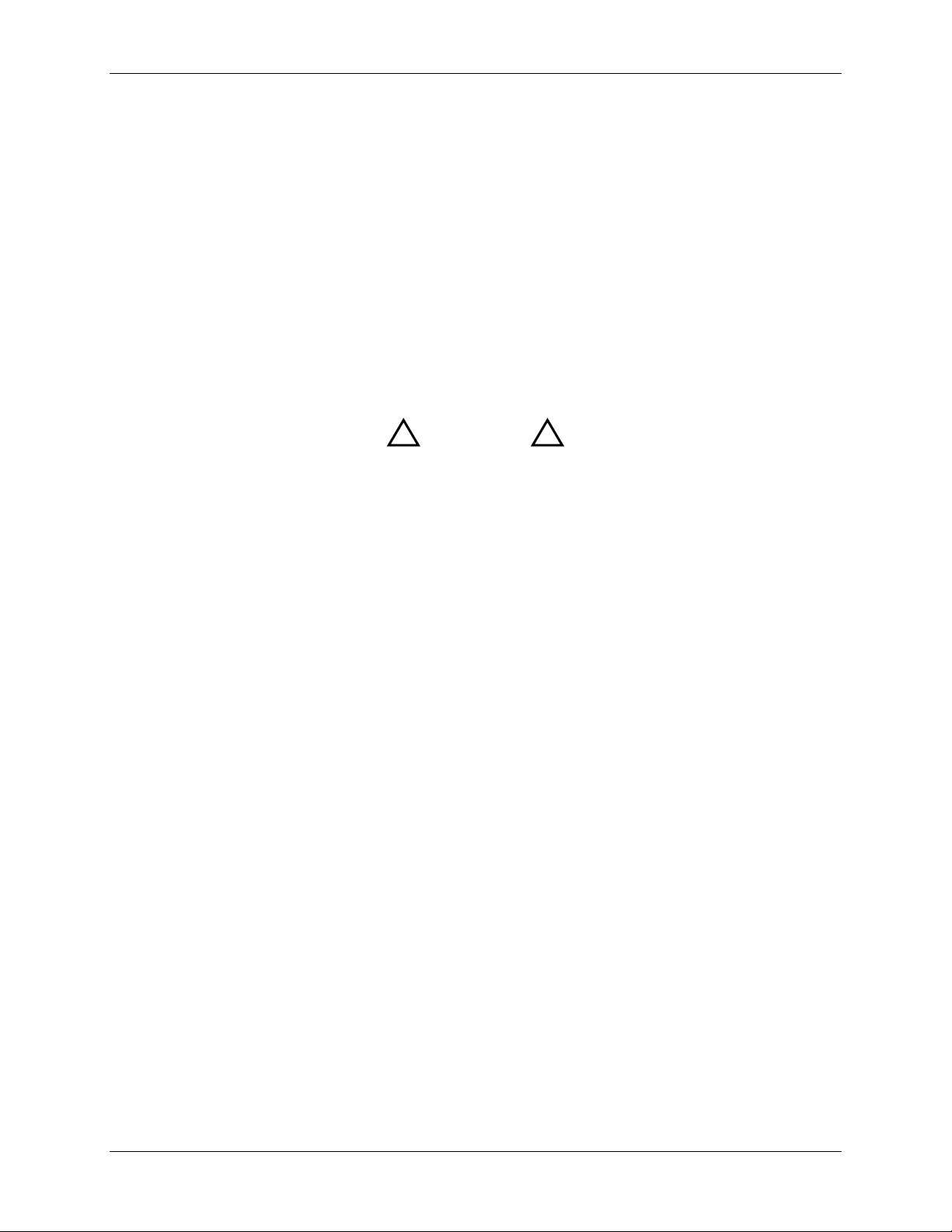
9) Page to the ACCS List and change the code to anything other than 24. The codE number
you have entered will flash off and then on to 0 to confirm that access is now set to OPEr
level and it is safe to return to use.
10) Confirm that the Addr is set properly by pressing Page button until the cmS list is
displayed and Scroll to Addr. If the value is correct, you are done. If not, then repeat the
steps over again.
VD2: 02/28/14 AERCO International, Inc. • 100 Oritani Dr. • Blauvelt, New York 10913 • Phone: 800-526-0288 Page 23 of 82
AC-105 OMM-0003_0D
Page 24

Electronic Control System (ECS) and Type CXT-E Valve
2. INSTALLATION
2.5 ENABLING REMOTE SETPOINT CONFIG URATION ON THE AERCO EUROTHERM TEMPERATURE CONTRO LLE R
The setpoint may be programmed to be remotely configured by executing the following steps.
See the previous instructions for changing communication addresses in the AERCO Eurotherm
Temperature Controller for more detailed directions for programming the controller.
1) Page to “ACCS”.
2) Scroll and enter code of 1.
3) Scroll and at the “GOTO” menu choose “Conf”.
4) At t he “Conf” screen enter the code of 2
5) Press the Scroll button once and then the Page button until you find “SP”.
6) Scroll until you find “rmt” and set the parameter value to “SP”.
7) Press the Page and Scroll button together at the same time to go to “exit”.
8) Press the Up arrow to select “yes” and then the instrument will reboot.
9) Onc e the instrument has returned to its normal state, press the Page button until you see
“SP”.
10) Scroll until you see “L-r” and using the Up arrow select “rmt”.
11) Once you have selected “rmt” press the Page and Scroll buttons at t he same t ime to return
to the normal temp display.
You should now be able to control the set point remotely.
Page 24 of 82 AERCO International, Inc. • 100 Oritani Dr. • Blauvelt, New York 10913 • Phone: 800-526-0288 VD2: 02/28/14
OMM-0003_0D AC-105
Page 25
Electronic Control System (ECS) and Type CXT-E Valve
!
!
3. ADJUSTMENT
3. ADJUSTMENT
3.1 INTRODUCTION
This Section provides adjustment procedures for both the Control Valve, Type CXT-E and t he
Electronic Control System (ECS).
Prior to shipment, from AERCO, all CXT-E Control Valve Actuators are adjusted (auto-stroked)
to ensure that they properly position the Control Valve from the fully-open to the fully-closed
positions. In addition, the ECS is adjusted to the Setpoint Temperature specified on the Sales
Order. If no setting was specified, the default is 140°F.
It is recommended that the following procedures be performed to the extent necessar y, prior to
placing the system into operation. Also, the applicable procedures MUST be performed
following replacement of the CXT-E Control Valve or other ECS components. In addition, the
following procedure must be performed following maintenance or adjustment of linkage,
actuator or packing nut.
CAUTION
As a precaution, ensure that all heating fluid (steam or hot
(boiler) water) shutoff valves are fully closed prior to performing
any of the following adjustment procedures.
3.2 CONTROL VALVE TYPE CXT-E ADJUSTMENT
All CXT-E Actuators are powered by 24 VDC and are contr olled by a linear 4-to-20 mA control
signal. A 4 mA control signal input places the Control Valve in the fully-closed position(Valve
shaft down); while a 20 mA signal strokes the Valve to the fully-open position (Valve shaft up).
The Control Valve Actuators are self-calibrating for all Valve sizes. Therefore, simply proceed as
follows to automatically adjust the Actuator:
NOTE:
The following adjustment procedure must be performed any time that
the CXT-E Actuator is replaced or a mechanical adjustme nt is ma de
to the Linkage Assembly or Valve.
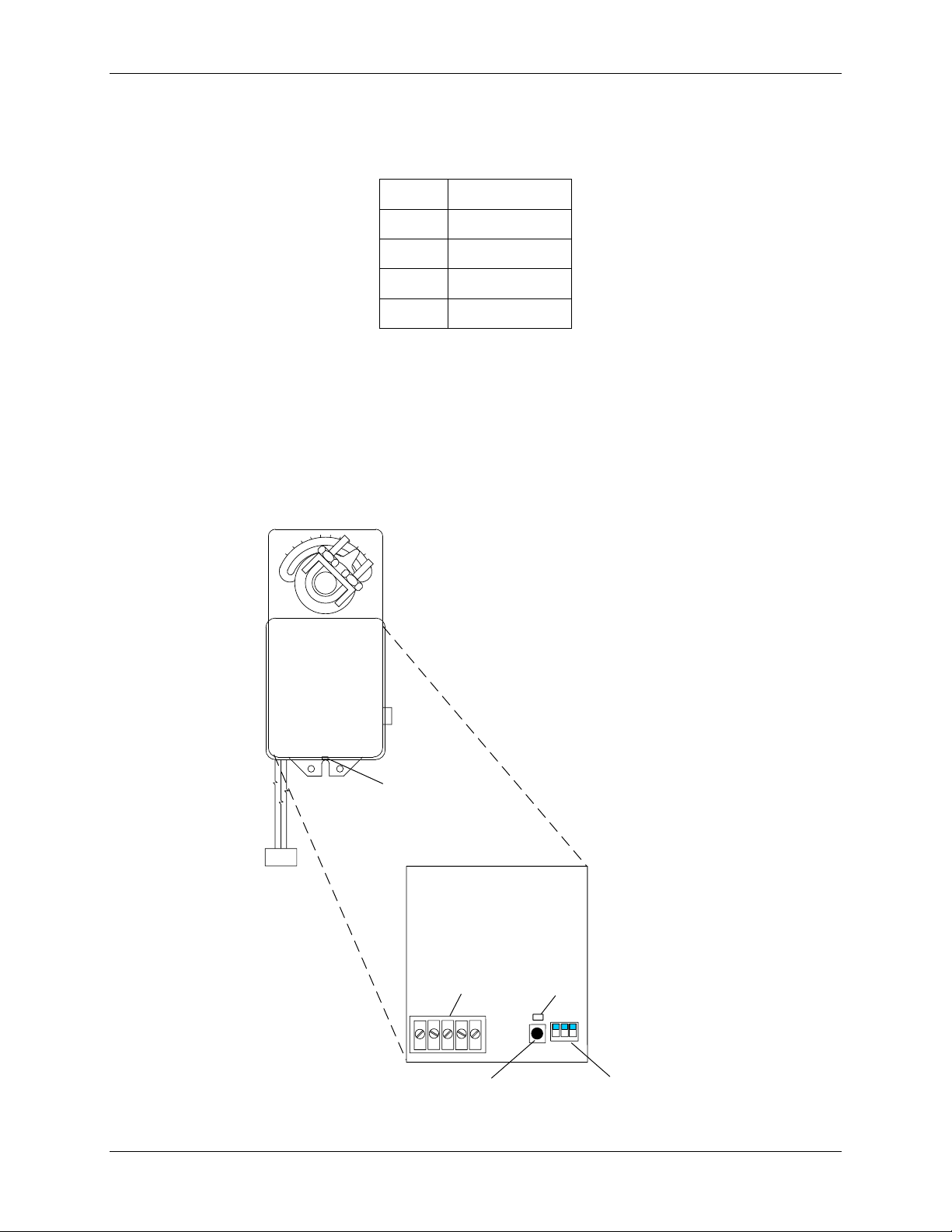
1) Refer to Figure 3-1 and loosen the Actuator cover set screw.
2) Remove the Actuator cover to access the PC Board containing the terminal connections,
DIP switches, Auto-Stroke (Reset) button and LED shown in Figure 3-1.
NOTE:
When properly connected to the ECS, +24 VDC power is supplied to
the Control Valve Actuator when the Control Box POWER switch is
set to the ON position. This switch is located on the right side of the
Control Box.
3) Set the ECS Control Box POWER switch to the ON position to apply 24 VDC power to the
Actuator (pin 2 = +24 VDC, pin 1 = Common). The LED will light indicat ing that power is
applied.
4) Wait approximately 10 seconds while the unit performs a self-test. The LED will blink fr om
one to four times depending on the size of the valve as follows:
VD2: 02/28/14 AERCO International, Inc. • 100 Oritani Dr. • Blauvelt, New York 10913 • Phone: 800-526-0288 Page 25 of 82
AC-105 OMM-0003_0D
Page 26
Electronic Control System (ECS) and Type CXT-E Valve
Valve Size
1”
1.25” and 2.5”
1.5” and 3”
2” and 4”
0
90
neptronic
1 2 3
1 2
3
4 5
1
2
3
DIP SWITCHES (3)
(ALL IN UP POSITION)
AUTO-STROKE
(RESET) BUTTON
LED
TERMINALS
PC BOARD
COVER
SET SCREW
ACTUATOR
3. ADJUSTMENT
NOTE:
DO NOT PRESS THE RESET BUTTON before the 10 second period
has ended.
Blinks
1
2
3
4
5) For Full-Stroke automatic adjustment, press the Reset button. The LED will light.
6) The Actuator will then rotate in both directions to find its open and closed Valve position
stops.
7) Upon successful completion of the automatic adjustment, the LED will blink 1 to 4 times
(depending on the valve size shown above) and then go off.
8) Replace and secure the Actuator cover by tightening the set screw.
Figure 3-1. Actuator Adjustment
Page 26 of 82 AERCO International, Inc. • 100 Oritani Dr. • Blauvelt, New York 10913 • Phone: 800-526-0288 VD2: 02/28/14
OMM-0003_0D AC-105
Page 27

Electronic Control System (ECS) and Type CXT-E Valve
WATER HEATER
TEMP CONTROLLER
B-PLUS
TM
HOLD
RUNAUTO
MAN
2408
PT.NO.
PT.NO.
OVER TEMP SWITCH
PANEL
DOOR
OVER-TEMP
SWITCH
TEMPERATURE
CONTROLLER
3. ADJUSTMENT
3.3 ELECTRONIC CONTROL SYSTEM (ECS ) ADJUSTMENT
The Electronic Control System (ECS) is preset at the setpoint temperature specified on the
Sales Order. The over-temperature alarm limit is normally set 20°F above the specified setpoint.
If no setpoint or over-temperature alarm limit is specified, the ECS will be set to the Factory
Default values of 140°F (setpoint) and 160°F (over-temperature alarm limit). If changes are
required, the setpoint and over-temperature alarm limits can be easily changed. This is
accomplished using the controls provided on the Temperature Controller and the OverTemperature Switch contained in the Control Box shown in Figure 3-2. These items can be
viewed through the window on the front door of the Control Box. To access thes e controls and
adjust the setpoint or over-temperature alarm limit, open the hinged Control Box door. Pr oceed
as follows to adjust the required parameters:
NOTE:
For “Water-to-Water” Heater applications, two additional
Temperature Display Indicators are mounted below the Over Temp
Switch. Although these Indicators are identical to the Over Temp
Switch, they are “Indicator-Only” devices which cannot be adjusted.
Figure 3-2. Control Box – Front View
NOTE:
When the Power Switch on the Control Box is set to the ON position,
it also energizes the internal DC Power Supply in the Control Box.
This in turn provides 24 VDC power to the Control Valve Actuator,
provided that the water temperature at the heater outlet is below the
VD2: 02/28/14 AERCO International, Inc. • 100 Oritani Dr. • Blauvelt, New York 10913 • Phone: 800-526-0288 Page 27 of 82
AC-105 OMM-0003_0D
high temperature limit setting.
Page 28

Electronic Control System (ECS) and Type CXT-E Valve
AUTO
RUN
MAN HOLD
OP 1
OP 2
SP2
REM
2408
3. ADJUSTMENT
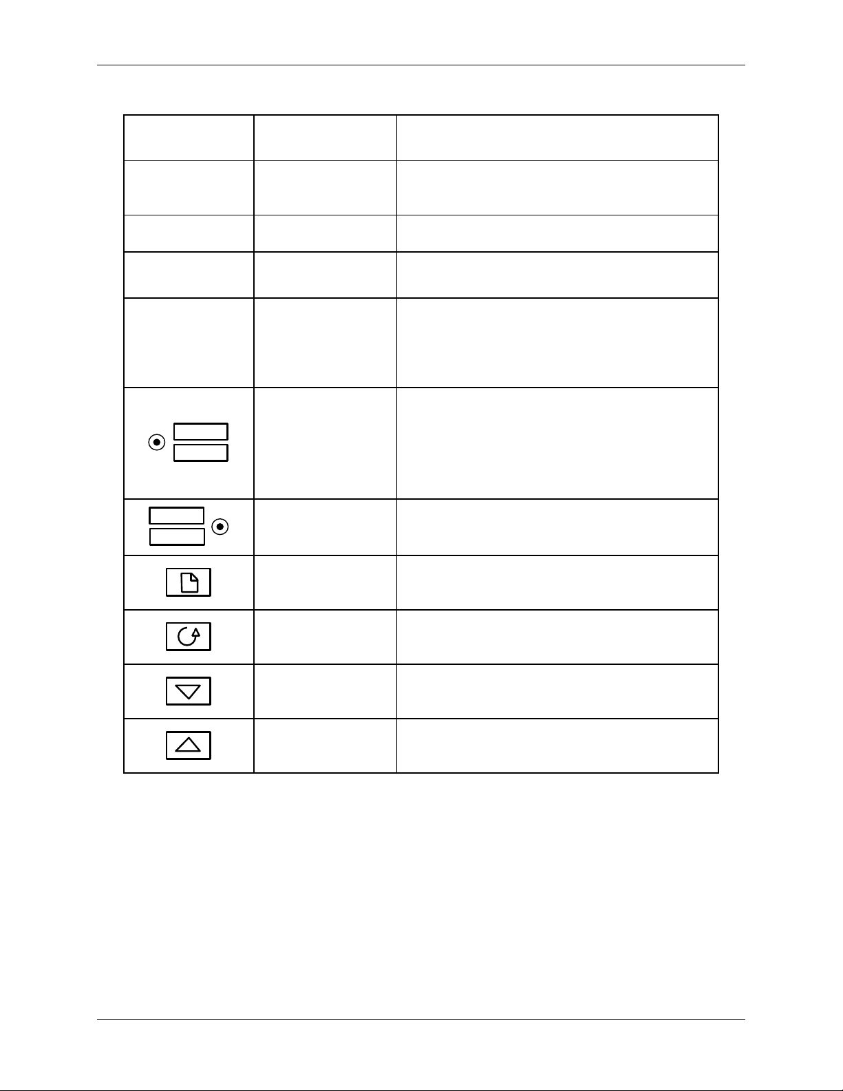
3.3.1 Se tpoi nt Te m perature Adjustment
The setpoint temperature is adjusted using the controls and displays provided on the
Temperature Controller. These controls and displays are illustrated and described in Figure 3-3
and Table 3-1. If necessary, setpoint temperature adjustment is accomplished as follows:
1) With the Control Box door open, set the ON/OFF POWER switch on the right side to the ON
position. The Temperature Controller will initiate a self-test for approximately 3 seconds.
Following the self-test, the top display will show the current outlet water temperature of the
Heater and the lower display will show the current setpoint temperature stored in memory
(default = 140°F).
2) Ensure that the Temperature Controller is set to the AUTO (automatic) mode and the AUTO
indicator is lit. If the MAN indicator is lit, press the AUTO/MAN button to toggle the mode
setting. Indicator OP1 will be lit if the process is calling for heat.
3) If the lower display does not show the desired setpoint temperature, press the ▲ or ▼ arrow
button to change the display to the desired value.
4) Two seconds after the ▲ or ▼ arrow button is released, the display will blink to indicate that
the Temperature Controller has accepted and stored the displayed value.
Figure 3-3. Temperature Controller
Page 28 of 82 AERCO International, Inc. • 100 Oritani Dr. • Blauvelt, New York 10913 • Phone: 800-526-0288 VD2: 02/28/14
OMM-0003_0D AC-105
Page 29
Electronic Control System (ECS) and Type CXT-E Valve
OP1 lights when a 4 to 20 mA signal is being
Not used for the ECS application
Setpoint 2
Indicator
Not used for the ECS application
REM lights when the ECS is set up to be
AUTO
MAN
When button is pressed, the Controller is
RUN
HOLD
Press Page button to select a new list of
Press Scroll button to select a new parameter
Press to decrease the value shown in the
Press to increase the value shown in the
3. ADJUSTMENT
Table 3-1. Temperature Controller Operating Controls, Indicators & Displays
CONTROL or
INDICATOR
OP1 Output 1 Indicator
OP2 Output 2 Indicator
SP2
REM
MEANING
Remote Setpoint
Indicator
Auto/Manual
Button and
Indicators
Run/Hold Button
and Indicators
FUNCTION
supplied to the ECS Valve Actuator
controlled by a Remote (Modbus) signal.
REM will also flash when Modbus
communication is active.
toggled between the automatic (AUTO) and
manual (MAN) modes.
AUTO lights when in the automatic mode.
MAN lights when in the manual mode.
Not used for ECS application
Page Button
Scroll Button
Down Button
Up Button
parameters
in a list
lower display
lower display
3.3.2 Over-Temperature Alarm Limit Adjustment
The over-temperature alarm limit setting is adjusted using the controls and display on the OverTemperature Switch. The controls and display are illustrated and described in Figure 3-4 and
Table 3-2. If necessary, over-temperature alarm limit adjustment is accomplished as follows:
1) With the Control Box door open, set the ON/OFF POWER switch to the ON position.
2) Press the SET button on the Over-Temperature Switch. SP will appear in the display.
3) Press the SET button again. The current over-temperature limit value stored in memory will
be displayed (default = 160°F).
VD2: 02/28/14 AERCO International, Inc. • 100 Oritani Dr. • Blauvelt, New York 10913 • Phone: 800-526-0288 Page 29 of 82
AC-105 OMM-0003_0D
Page 30

Electronic Control System (ECS) and Type CXT-E Valve
CONTROL or
INDICATOR
Displays current water temperature or setpoint.
Resets the unit after an alarm condition.
Increases the displayed temperature.
Decreases the displayed temperature.
Used to access and store parameters in the unit.
3. ADJUSTMENT
4) If the display does not show the desired over-temperature alarm setting, press the ▲ or ▼
arrow button to change the display to the desired temperature setting.
5) Once the desired over-temperature alarm setting is displayed, press the SET button to st ore
the setting in memory.
6) To exit the programming mode, press the SET and ▼ buttons simultaneously, or simply wait
one minute.
7) Once the programming mode has been exited, the display will show the current out let water
temperature of the Heater.
Figure 3-4. Over-Temperature Switch
Table 3-2. Over-Temperature Switch Controls and Indicators
MEANING FUNCTION
LED Display
RST
TEMP status
RESET Button
UP Button
DOWN Button
SET
SET Button
3.3.3 Over-Temperature Switch Sensor Adjustment
The Over-Temperature Switch can be adjusted to allow a ±10°F offset, in order to match the
value from a Eurotherm Temperature Controller. To use this function, complete the following
steps:
1) Press and hold the SET button for 8 to 12 seconds. The display will show 00. DO NOT
change these values.
2) Momentarily press the SET button. The SP parameter will be displayed.
3) Using the Up and Down arrow keys, scroll t o parameter P1.
4) Press the SET button. The display will show the current offset (default = 0).
5) Press the Up and Down arrows to enter the desired offset value (-10 to + 10°).
6) Press the SET button to store the selected offset value.
7) Press the SET and Down arrow buttons at the same time to quit the programming mode, or
wait one minute and the display will automatically exit the programming mode.
Page 30 of 82 AERCO International, Inc. • 100 Oritani Dr. • Blauvelt, New York 10913 • Phone: 800-526-0288 VD2: 02/28/14
OMM-0003_0D AC-105
Page 31

Electronic Control System (ECS) and Type CXT-E Valve
4. OPERATION
4. OPERATION
4.1 INTRODUCTION
This Section provides the pre-operational checks, initial start-up procedures for the AERCO
Water Heater, Electronic Control System (ECS) and CXT-E Control Valve. In addition,
procedures are included to check the hot water outlet flow through the heater.
4.2 PRE-OPERATIONAL CHECKS
1) Verify that the ECS Temperature Controller setpoint and Over-Temperature Switch alarm
limit have been properly set using the procedures in Section 3 – ADJUSTMENTS.
2) Refer to Figure 2-1 (Steam Flow) or Figure 2-2 (Hot Water Flow). To place the Control Valve
and Heater System into operation, proceed as follows:
a) Ensure that the AERCO Heater is ready for operation in accordanc e with the instructions
provided in the Heater Operation & Maintenance Manual included with the equipment.
b) First, slowly open the upstream and the downstream shutoff valves until they are fully
open. Check to insure that the CXT Valve is not allowing the flow of steam or hot water.
c) Ensure t hat electrical power is properly connected to the ECS Control System and the
Electronic Control Valve, Type CXT-E.
4.3 INITIAL START-UP
In order to prevent a possible over-temperature condition during initial start-up, aerco
recommends that the following steps be performed in the order specified:
1) With the ECS Control Box door open, set the POWER switch on the right side of the box to
the ON position. This will provide power to the complete ECS and CXT-E Control Valve.
When power is initially applied, the ECS Temperature Controller automatically performs a
self-test sequence for approximately three seconds. Proceed immediately to the next step.
2) Upon completion of the self-test, the Temperature Controller will show the present water
heater outlet temperature in the upper display and the setpoint temperature in the lower
display.
3) Press the AUTO/MAN button on the front panel of the Controller (Figure 3-3) and toggle the
display to the MAN (Manual) mode. The MAN indicator will light when the Manual mode is
selected.
4) When in the Manual mode, the upper display will continue to show the current outlet water
temperature of the heater. The lower display will show the position of the CXT-E Control
Valve Actuator in %. When the Manual mode is initially selected, the lower display will show
0%, indicating that the Control Valve is fully closed.
5) Using the ▲ arrow button, set the CXT-E Control Valve to the 10% position and monitor the
outlet water temperature of the heater.
6) Next, continue to increase the valve “open” position in 5% increments until the water
temperature starts to increase at a moderate rate.
7) When the outlet water temperature has increased to within 20°F of the desired setpoint,
press the AUTO/MAN button and toggle the Temperature Controller to the AUTO mode. The
AUTO indicator will light and the MAN indicator will go off. When in the AUTO mode the
upper display will continue to show the outlet water temperature of the heater. The lower
display will show the selected setpoint temperature.
VD2: 02/28/14 AERCO International, Inc. • 100 Oritani Dr. • Blauvelt, New York 10913 • Phone: 800-526-0288 Page 31 of 82
AC-105 OMM-0003_0D
Page 32

Electronic Control System (ECS) and Type CXT-E Valve
4. OPERATION
8) When in the AUTO mode, the ECS will stabilize at the selected setpoint temperature (see
Section 3). Once stabilized, the ECS is set for unattended operation with no further operator
intervention.
IMPORTANT NOTE:
In order to accurately measure the outlet flow rate of the AERCO
Water Heater, it is imperative that the properly sized inlet orifice be
installed in the cold water inlet. Failure to do so will result in
erroneous flow rate readings.
4.4 CHECKING WATER HEATER FLOW R ATE
If desired, the water heater outlet flow rate in gallons per minute (GPM) can be monitored using
the controls and displays on the Temperature Controller. This is accomplished as follows:
1) Press the Scroll (
2) When Li.2 is shown in the upper display, the lower display will show the water heater outlet
flow rate in gallons per minute (GPM). The flow rate will be displayed for several seconds
and then the Controller will revert to the default displays (outlet water temperature and
setpoint).
) button and scroll to Li.2.
4.5 CHECKING THE VALVE POSITION OUTPUT IN AUTO MODE
1) Press the Scroll ( ) button and scroll to OP.
2) The display will indicate the percent open from 0 to 100. This should be checked with the
indicator scale on the CXT valve linkage. See Figure 1-4 for scale location.
Page 32 of 82 AERCO International, Inc. • 100 Oritani Dr. • Blauvelt, New York 10913 • Phone: 800-526-0288 VD2: 02/28/14
OMM-0003_0D AC-105
Page 33

Electronic Control System (ECS) and Type CXT-E Valve
5. FUNCTIONAL DESCRIPTION
5. FUNCTIONAL DESCRIPTION
5.1 INTRODUCTION
The AERCO Electronic Control System (ECS) and Electronic Control Valve Type CXT-E
provide a highly responsive control system which provides virtually constant hot water flow at
the selected setpoint temperature. A simplified functional block diagram for the ECS and CXT-E
is shown in Figure 5-1. The following paragraphs provide a top-level functional overview of
system operation.
5.2 FUNCTIONAL OVERVIEW
The primary control mechanism for the ECS is an Electronic Process Controller which is
installed in the Control Box. The Controller utilizes PID (Proportional Integral Derivative)
algorithms to provide precise control of the Water Heater outlet temperature. Outlet temperature
control is accomplished by modulating the open/closed position of the CXT-E Control Valve
Actuator.
The Controller continuously monitors the Water Heater outlet temperature via a thermocouple
located in the outlet port. The Controller also receives a feed-forward signal from the flow
sensor mounted in the cold water inlet as shown in Figure 5-1. The f low sensor monitors flow
changes through the Water Heater and provides a feed-forward signal (0 to 5 VDC) to the
Controller proportional to the change in flow.
Using PID algorithms, the Controller provides a 4-to-20 mA output signal to the CXT-E Control
Valve Actuator. This 4-to-20 mA signal proportionally modulates the Control Valve position from
fully closed (4 mA) to fully open (20 mA). The control signal varies as necessary to maintain the
setpoint temperature programmed into the Controller. Under normal conditions, the Water
Heater outlet temperature is maintained within ±4°F of the desired setpoint based on a load
change of 50% or less.
5.3 OVER-TEMPERATURE CONTROL AND SAFETY FEATURES
The Control Box also contains an Over-Temperature Switch which continuously monitors and
displays the outlet water temperature of the Heater via the input received from the thermocouple
installed in the hot water outlet port. Normally, the Over-Temperature Switch is set 20°F above
the setpoint temperature for the Water Heater. If the configurable over-temperature limit is
exceeded, the Over-Temperature Switch alarm is triggered, which sounds an audible alarm,
disconnects power from the Control Valve Actuator and energizes the Solenoid Valve located in
the Water Heater top head, expelling over-heated water from the Heater.
The Solenoid Valve in the top head remains open until the water tem perature drops below the
over-temperature limit setting. Once the water temperature drops below the limit, the OverTemperature Switch resets automatically, silencing the audible alarm, de-energizing and closing
the Solenoid Valve, and reapplying power to the Control Valve Actuator.
It should be noted that the Over-Temperature Switch has a slightly slower response to
temperature changes than the Temperature Controller. Therefore, slightly differ ent temperature
readings may appear momentarily in their respective displays, particularly during system startup.
The Control Valve Actuator also incorporates a “Fail-Safe” feature which automatically closes
the Valve if there is a loss of the 4-to-20 mA control signal or loss of input power.
VD2: 02/28/14 AERCO International, Inc. • 100 Oritani Dr. • Blauvelt, New York 10913 • Phone: 800-526-0288 Page 33 of 82
AC-105 OMM-0003_0D
Page 34

COLD
WATER
IN
ACTUATOR
FLOW
SENSOR
HEAT
EXCHANGER
CONTROL VALVE
CXT-E
STEAM
IN
4 – 20 mA CONTROL SIGNAL
FEED-FWD SIGNAL
TO
DRAIN
OVER-TEMP
SOLENOID
VALVE
TEMPERATURE
CONTROLLER
120 VAC
IN
HOT
WATER
OUT
DUAL OUTLET TEMPERATURE THERMOCOUPLE
CONTROL BOX
HEAT
EXCHANGER
OVER-TEMP
24
VDC
DC POWER
SUPPLY
(0 – 5 VDC)
24 VDC IN
CONDENSATE OUT
WATER TEMPERATURE
TEMP
SWITCH
24
VDC
12
VDC
Electronic Control System (ECS) and Type CXT-E Valve
5. FUNCTIONAL DESCRIPTION
Figure 5-1. ECS Simplified Block Diagram
Page 34 of 82 AERCO International, Inc. • 100 Oritani Dr. • Blauvelt, New York 10913 • Phone: 800-526-0288 VD2: 02/28/14
OMM-0003_0D AC-105
Page 35

Electronic Control System (ECS) and Type CXT-E Valve
INDICATOR
PLATE
VALVE
TOP
PACKING
NUT
P/O LINKAGE
ASSEMBLY
LOWER
SHAFT
!
!
6. ROUTINE MAINTENANCE
6. ROUTINE MAINTENANCE
6.1 INTRODUCTION
The following paragraphs provide the AERCO recommended routine maintenance procedures for the
Electronic Control Valve Type CXT-E and the Electronic Control System (ECS).
6.2 CXT-E CONTROL VALVE ROUTINE MAINTENANCE
6.2.1 Monthly Maintenance
Once each month, check the Control Valve for leakage as follows:
1) Refer to Figure 6-1 and check the Packing Nut and Valve Top for evidence of leak age.
CAUTION
Over-tightening the Packing Nut may trap the Valve Stem and
slow or stop Valve motion.
a) If there is leakage between the Packing Nut and Valve Top, tighten the Packing Nut
until the leakage stops. DO NOT FORCE the Packing Nut.
6.2.2 Semi-Annual Maintenance:
Every six months, check the following items:
1) Refer to Section 3 - ADJUSTMENT and perform the Actuator adjustment procedure
2) Clean the Strainer in the heating fluid line (Figure 2-1 or Figure 2-2) in accordance with the
b) If tightening the Packing Nut does not stop the leak, the Packing Nut and Packing
Assembly must be replace in accordance with the procedures specified in the Cont rol
Valve CORRECTIVE MAINTE NANCE Se c tion.
Figure 6-1. Valve Shaft Seals
specified. Verify that the Actuator strokes the Control Valve from the fully closed to the fully
open position.
instructions furnished with the Strainer.
VD2: 02/28/14 AERCO International, Inc. • 100 Oritani Dr. • Blauvelt, New York 10913 • Phone: 800-526-0288 Page 35 of 82
AC-105 OMM-0003_0D
Page 36

Electronic Control System (ECS) and Type CXT-E Valve
!
!
6. ROUTINE MAINTENANCE
6.3 ELECTRONIC CONTROL SYSTEM (ECS ) RO UTINE MAINTENANCE
6.3.1 Quarterly Maintenance:
Every three months, check the operation of the Over-Temperature Switch as follows:
WARNING
THIS PROCEDURE WILL RELE ASE HOT WATER. TAKE APPRO PRIATE
PRECAUTIONS TO AVOID BURNS.
1) Refer to Section 3 (ADJUSTMENTS) and lower the Over Temperature setting to
approximately 5°F below the present Setpoint shown in the lower display of the
Temperature Controller.
2) Verify that an Over-Temperature Alarm is generated and the following events occur:
• The CXT -E Control Valve closes.
• The Over-Temperature Solenoid (located at top of Heater) opens and expels water from
the system.
• The Over-Temperature Switch generates an audible alarm.
3) Following successful completion of the Over-Temperature Alarm check, return the Over-
Temperature Switch setting to its original Over-Temper ature setting.
6.3.2 Annually:
Once each year, AERCO recommends that the Temperature Sensor(s) and Flow Sensor be
checked to ensure there is no scale build-up or clogging that may degrade system operation.
Proceed as follows:
1) Close the upstream and downstream water supply valves to the Heater.
2) For W ater-to-Water Heaters ( E-Plus or Double-Wall) where hot boiler water is the heating
fluid, turn off the inlet and outlet valves in the fluid lines.
3) Check the Temperature Sensors and Flow Sensor as described in the following paragraphs
and steps. Upon completion of the Annual checks, restore the Heater to operation by
opening all valves which were closed in steps 1 and 2 above.
6.3.3 Temperature Sensors:
The Heater contains a Dual Temperature Sensor in the Heater outlet port. In addition, Water to
Water Heaters (E-Plus or Double-Wall) using hot (boiler) water as the heating fluid also contain
single-Element Sensors in the heating fluid inlet a nd outlet lines. Check and, if necessary, clean
these items by performing the following step:
1) Disconnect and remove the Dual Temperature Sensor (Thermocouple) at the Heater out let
and inspect for evidence of scale buildup on the stainless steel sleeve. If necessary, clean
the sensor using a wire brush.
2) For W ater-to-Water Systems, repeat step 1 for the Single-Element Sensors in the heating
fluid inlet and outlet lines.
3) After cleaning, reinstall the sensor(s) and ensure they are securely tightened.
Page 36 of 82 AERCO International, Inc. • 100 Oritani Dr. • Blauvelt, New York 10913 • Phone: 800-526-0288 VD2: 02/28/14
OMM-0003_0D AC-105
Page 37

Electronic Control System (ECS) and Type CXT-E Valve
TURBINE SHAFT
MAGNETS (2)
TURBINE PADDLE WHEEL
PADDLE WHEEL INSERT
O-RING
O-RING
GROOVE
CLEAR POLYCARBONATE
WINDOW
SNAP RING
STRAIN
RELIEF
6. ROUTINE MAINTENANCE
6.3.4 Flow Sensor:
The Flow Sensor is installed between the Heater water inlet line and the Heater drain ( refer to
Figures 1-1 & 5-1). Check this sensor for evidence of blockage or scale build-up as follows:
1) Disconnect the electrical connector from the Flow Sensor.
2) Loosen the fittings at the Sensor inlet and outlet connections and completely remove the
Sensor. To ease removal, loosen the strain relief on the flow sensor cable. This creates
clearance for the removal of the fitting on the meter body.
3) Inspect the Sensor inlet and outlet for blockage and clean as necessary.
4) Refer to Figure 6-2 and disassemble the Flow Sensor as follows:
a) Remove the internal snap-ring.
b) Remove the clear polycarbonate window and O-ring.
c) Remove the turbine paddle wheel.
d) Clean all foreign matter from the Flow Sensor. If replacement parts are needed, order
the appropriate Flow Sensor Rebuild Kit (see Table 9-2) fr om your local AERCO Sales
Representative.
Figure 6-2. Flow Sensor, Part No. 64006 – Exploded View
VD2: 02/28/14 AERCO International, Inc. • 100 Oritani Dr. • Blauvelt, New York 10913 • Phone: 800-526-0288 Page 37 of 82
AC-105 OMM-0003_0D
Page 38

Electronic Control System (ECS) and Type CXT-E Valve
! ! !
!
6. ROUTINE MAINTENANCE
5) After cleaning, reassemble the Flow Sensor as follows:
IMPORTANT NOTE!
Ensure that the paddle wheel magnets are installed facing the
internal wall of the Flow Sensor. If not correctly installed, the Sensor
will not function properly.
a) Reinstall the paddle wheel.
b) Apply a thin film of silicone grease on the O-ring in the groove of the clear
polycarbonate window.
c) Reinstall the polycarbonate window.
d) Reinstall the snap-ring.
6) After the Flow Sensor has been reassembled, reinstall the Sensor. Tighten the strain relief
and connect the electrical connector.
6.4 HEAT EXCHANGER ROUTINE MAINTENANCE CLEANING
AERCO recommends that the heat exchanger of the unit be cleaned annually using a solution
of Hydroskrub and water. Hydroskrub is distributed by AERCO International, Inc. and is
designed to dissolve the toughest water scale, lime, mud and rust deposits from virtually any
type of water-based equipment.
NOTE:
The following cleaning procedure applies to all sizes WWDW and
SWDW Heaters. For Helical Coil Type Water Heaters, refer to the
applicable manuals listed in Section 1, page 1-8 of this document for
cleaning/descaling procedures.
CAUTION
Please review MSDS, specifications, and our website
www.aerco.com for additional information, or call technical
service at (800) 526-0288.
CAUTION
Do not drain the unit without venting the shell! A vacuum in the
unit may displace the liner causing serious damage not covered
by warranty.
6.4.1 Pumpi ng System Set-Up Instructions:
Refer to the sample pumping set-up diagram shown in Figure 6-3 for a Double-Wall Heat
Exchanger. For Helical Coil Heaters, refer to the applicable manuals listed in Section 1,
paragraph 1.4.
1) Turn off the water heater and close the inlet and outlet isolation valves.
2) Drain at least half of the water-side volume from the heat exchanger. The amount of water
drained will depend on the size of the heater.
3) Prepare a 50% solution of Hydroskrub and clean water. The amount of the solut ion should
be approximately equal to the full volume of water that the heat exchanger holds.
4) Close the drain valve and connect a suitable size bucket and pump to the unit drain as
shown in Figure 6-3.
Page 38 of 82 AERCO International, Inc. • 100 Oritani Dr. • Blauvelt, New York 10913 • Phone: 800-526-0288 VD2: 02/28/14
OMM-0003_0D AC-105
Page 39

Electronic Control System (ECS) and Type CXT-E Valve
CIRCULATED HYDROSKRUB SOLUTION
FROM TOP OF HEAT EXCHANGER INTO
BUCKET
NOTE: IF A HOSE CONNECTION IS NOT
AVAILABLE IN THE HOT WATER OUTLET
PIPING, UNUSED PORT AT THE TOP OF
THE HEAT EXCHANGER, IF AVAILABLE,
MAY BE USED.
HYDROSKRUB SOLUTION CIRCULATED
FROM THE BOTTOM OF BUCKET TO THE
DRAIN CONNECTION OF THE HEAT
EXCHANGER.
CLOSE THE
COLD WATER INLET
ISOLATION VALVE
CLOSE THE
HOT WATER OUTLET
ISOLATION VALVE
DRAIN VALVE
HOSE CONNECTION
CIRCULATING
BUCKET
6. ROUTINE MAINTENANCE
5) Install a valve and hose connection in the outlet piping of the heater (Figure 6-3) and rout e
the hose back to the top of the circulation bucket.
Figure 6-3. Sample HydroSkrub Pumping System Set-Up for Double-Wall Heater
6.4.2 Cleaning Procedure:
1) Slowly add the prescribe amount of the Hydroskrub solution to the circulating bucket.
2) Open the drain and outlet hose connection valves and turn on t he pump. Periodically check
for leaks and maintain the liquid level in the bucket. A lowering volume level is an indication
that there is an open drain in the system.
3) Check the cleaning circuit to ensure that the HydroSkrub solution is flowing from the
circulation bucket, through the pump and the heater and back to the top of the top of the
bucket.
4) Return discharge foaming indicates an active HydroSkrub solution and the presence of
mineral deposits in the equipment.
5) Additional HydroSkrub and/or water may be required to maintain circulation and to prevent
the pump from cavitating.
6) Circulate through the Heat Exchanger and piping for 1 to 3 hours. Estimate the circulation
period based on the time in service and water hardness. If the heating equipment is more
than 40 gallons, the circulation time may need to be extended to complet e cleaning. When
foaming action stops, HydroSkrub strength is depleted (two pounds of deposits removed per
gallon used) or the equipment is free from calcium and other water-formed mineral deposits.
VD2: 02/28/14 AERCO International, Inc. • 100 Oritani Dr. • Blauvelt, New York 10913 • Phone: 800-526-0288 Page 39 of 82
AC-105 OMM-0003_0D
Page 40

Electronic Control System (ECS) and Type CXT-E Valve
6. ROUTINE MAINTENANCE
7) Periodically test the solution for effectiveness to determine if more HydroSkrub is needed.
Refer to “Testing hydroSkrob Effectiveness” in the next paragraph for details. If t he cleaning
solution is expended before circulation time is up, additional HydroSkrub will be needed and
circulation time may be extended to complete the cleaning.
8) Upon completion of t he cleaning process, begin flushing the solution by adding clean water
to the circulation bucket, then disconnect the return valve and hose connection from the top
of the circulating bucket and thoroughly flush. Continue water flushing the equipment for a
minimum of 10 minutes or until discharge runs clear.
9) HydroSkrub is biodegradable, and in most instances may be purged down sewers. Check
with local authorities before disposing of any complex compositions
10) Turn off water, shut off the pump and immediately close discharge valves to prevent
backflow.
11) Completely drain pump bucket. Disconnect hoses from equipment and thoroughly rinse the
bucket, pump, and associated hoses used.
6.4.3 Testing HydroSkrub Effectiveness
There are two methods of testing the effectiveness of HydroSkrub during cleaning: the calcium
carbonate spot test of the circulating solution and the charting of a trend in the pH of the
cleaning solution.
6.4.4 Calcium Carbonate Spot Test:
A calcium carbonate spot test is performed by exposing a form of calcium carbonate to the
HydroSkrub solution. Samples of the deposit, a Tums or Rolaids tablet, or bare concrete can be
used. Observe the reaction of the HydroSkrub solution on the calcium carbonate. Foaming and
bubbling indicates the solution is still active. Little or no reaction indicates that the solution is
expended. This test should be performed near the end of the circulat ing time. If the solution has
been expended, more HydroSkrub will be required to complete the job. If the solution is still
active at the end of the time, all the scale has been dissolved.
6.4.5 pH Trend Charting:
The initial pH of the cleaning solution will measure between 1-3 (See pH sheet on HydroSkrub
packaging). To test the effectiveness of the circulating solution as a function of pH, take
readings at regular intervals and chart as a trend. Note that the deposits can cause a premature
jump in the pH. After circulating for approximately 75% of the cycle time, begin testing the pH at
10-15 minute intervals. Once the solution’s pH reads 6.0-7.0 on three or more consecutive
readings, the solution is expended. If the pH reads below 6.0 after the circulating time, the
application is clean.
Page 40 of 82 AERCO International, Inc. • 100 Oritani Dr. • Blauvelt, New York 10913 • Phone: 800-526-0288 VD2: 02/28/14
OMM-0003_0D AC-105
Page 41

Electronic Control System (ECS) and Type CXT-E Valve
7. TROUBLESHOOTING
7. TROUBLESHOOTING
7.1 INTRODUCTION
This Section provides the troubleshooting procedures necessary to isolate faults to the most
probable cause(s) for a malfunction of the Electronic Control System (ECS) or Electronic
Control Valve Type CXT-E. Prior to performing the troubleshooting steps and procedures
specified in this Section, perform the following preliminary checks:
NOTE:
In addition to the procedures contained in this Section, also check the
Troubleshooting Sections of the AERCO Heat Exchanger Manual
and any other ancillary equipment manuals included with the
installation.
7.1.1 Electronic Control System (ECS) Preliminary Check:
a) Check to ensure that all ECS electrical cable connections are secure.
b) Ensure that the CXT-E Control Valve actuator is connected to the Control Box cable plug.
7.1.2 Electronic Control Valve, CXT-E Preliminary Check:
a) Verify that all connections have been made in accordance with Figure 2-1 (Steam Flow)
or Figure 2-2 (Hot (Boiler) Water Flow).
b) Ensure that the Control Valve is installed with the flow arrow on the Valve Body pointing
in the direction of flow.
c) Ensure that both the upstream and downstream shutoff valves are fully open.
7.2 TROUBLESHOOTING PROCEDURES
The troubleshooting procedures are provided in Table 7-1 (Control Valve CXT-E) and Table 7-2
(ECS) which follow. Also, when troubleshooting ECS faults related to the Temperature
Controller (Eurotherm, Model 2408), additional information concerning process fault and
diagnostic alarms is included in Appendix A. When a fault occurs, proceed as follows:
1) Refer to the FAULT INDICATION column in the following tables and locate the fault that
best describes the existing conditions.
2) Proceed to the PROBABLE CAUSE column and, if more than one item is listed, s t art with
the first item shown for the fault condition.
3) Perform the corresponding checks and procedures listed in the CORRECTIVE ACTION
column for the first PROBABLE CAUSE.
4) Continue checking each additional PROBABLE CAUSE for the existing fault until the fault
has been corrected.
5) Refer to the applicable procedures in Section 8 – CORRECTIVE MAINTENANCE if
component removal and/or replacement is required.
VD2: 02/28/14 AERCO International, Inc. • 100 Oritani Dr. • Blauvelt, New York 10913 • Phone: 800-526-0288 Page 41 of 82
AC-105 OMM-0003_0D
Page 42

Electronic Control System (ECS) and Type CXT-E Valve
FAULT
INDICATION
1. No power supplied
1. Disconnect Valve Actuator plug and
1. Control Valve not
1. Check the 4 – 20 mA control signal
1. Temp. Controller not
1. Refer to Section 3 –ADJUSTMENTS.
7. TROUBLESHOOTING
Table 7-1. Troubleshooting – Control Valve CXT-E
NO.
T1
T2
System not
operating.
Control Valve is
closed and
outlet water
temp. is far
below setpoint.
System overheats by more
than 10°F above
the desired
setpoint.
Outlet temp is
below OverTemp limit setting
CAUTION!
Over-tightening
the Pack-ing nut
may trap the
Valve Stem and
slow or stop
Valve motion.
PROBABLE CAUSE CORRECTIVE ACTION
to Control Valve
2. Control signal not
being supplied from
Temp. Controller.
fully closed.
2. Temp. Controller not
set properly or
defective.
3. Valve Actuator not
properly secured to
Linkage Assembly.
4. Foreign matter in
Valve Seat
verify that 24 VDC power is present at
pin 2 of Actuator cable. Restore power if
necessary. If System includes ECS,
proceed to Table 7-2 and check OverTemp Switch to ensure it has not
tripped.
2. Verif y presence of 4 - 20 mA control
signal at pin 3 of Actuator cable. If
control signal is not present,
troubleshoot ECS per Table 7-2.
being supplied to Actuator. If signal is
greater than 4 mA when heater outlet
temperature is 10°F (or more) above the
desired setpoint, proceed to next item in
list.
2. Refer to Section 3 – ADJUSTMENTS
and check current setting of Temp.
Controller. Readjust if necessary. If
adjustment does not clear fault, proceed
to Table 7-2 and continue.
3. Check Actuator U-bolt securing it to
Linkage Assembly. Tighten if needed
and readjust the CXT-E Control Valve
per Section 3.
4. If Valve still does not close after
checking the above items, disassemble
the Valve and clean the Seat per steps
CM18 – CM28 in Section 8.
System outlet
water
temperature is
below desired
setpoint
T3
CAUTION!
Page 42 of 82 AERCO International, Inc. • 100 Oritani Dr. • Blauvelt, New York 10913 • Phone: 800-526-0288 VD2: 02/28/14
OMM-0003_0D AC-105
Over-tightening
the Packing nut
may trap the
Valve Stem and
slow or stop
Valve motion.
properly set
2. Control Valve not
opening properly.
Check the current ECS Temp.
Controller setting. If the setting is below
the desired setpoint, readjust as
necessary.
2. Check as follows:
• Ensure Actuator is secured to Linkage
Assembly. Tighten if needed.
• Verify that 24 VDC power and 4 – 20
mA control signal are present at
Actuator pins 2 and 3 respectively.
• To ensure Valve is not binding, check
Seal Retainer per steps CM1-CM10 of
Section 8 Corrective Maintenance.
Replace items as necessary.
Page 43

Electronic Control System (ECS) and Type CXT-E Valve
NO.
FAULT INDICATION
PROBABLE CAUSE
CORRECTIVE ACTION
3. Steam pressure, or
3. Check the high side steam pressure
Wide variations in
wide variations in flow.
7. TROUBLESHOOTING
Table 7-1. Troubleshooting – Control Valve CXT-E (Continued)
(Continued)
System outlet water
T3
temperature is below
desired setpoint
heating fluid
temperature too low.
4. For Steam Heating
System, Trap or Orifice
in Heater Condensate
Line is malfunctioning.
to the Control Valve to ensure it is
correct. For high temperature (HT)
water, ensure there is good
circulation.
a. If steam pressure or HT water
temperature is lower than the system
design spec., correct as necessary.
b. If high side steam pressure drops, or
there is no HT water circulation as
the Control Valve opens, there may
be a partially closed valve in the
upstream line. Also, the strainer may
be clogged. Correct as needed.
4. Check for improper operation of Trap or
clogged Orifice in Condensate Line as
follows:
a. If low side pressure gauge shows
pressure but steam does not heat
properly, CAREFULLY bre ak
Condensate Line connection AHEAD
of Trap or Orifice.
b. Allow condensate to run out into floor
drain.
Heater outlet
T4
temperature during
Rapid fluctuations in
heater outlet
T5
temperature which do
not follow load
changes
ECS Flow Sensor not
functioning properly
1. Temp. Controller not
functioning properly.
2. Steam System Trap or
Orifice fault
c. If Heater outlet temperature rises to
desired setpoint with condensate
connection open, repair or replace
Trap or unplug Orifice.
Refer to Table 7-2 and ch eck operat ion of
Flow Sensor.
1. Refer to Table 7-2 and troubleshoot
Temperature Controller.
2. Refer to T3, Corrective Action 4 above
and proceed as indicated.
VD2: 02/28/14 AERCO International, Inc. • 100 Oritani Dr. • Blauvelt, New York 10913 • Phone: 800-526-0288 Page 43 of 82
AC-105 OMM-0003_0D
Page 44

Electronic Control System (ECS) and Type CXT-E Valve
1. External 120
1. Ensure external circuit breaker is ON. Check
Assembly.
is securely
Check to ensure that the Actuator is
1. Over-Temp Switch
1. Refer to Section 3 and check the current
Temp. Switch.
7. TROUBLESHOOTING
Table 7-2. Troubleshooting – Electronic Control System (ECS)
NO. FAULT INDICATION
System not operating.
T6
All displays are blank.
PROBABLE
CAUSE
VAC power
disconnected.
2. Defective
ON/OFF switch
on Control Box.
3. Defective DC
Power Supply.
1. Temp. Controller
is not properly
set.
CORRECTIVE ACTION
for 120 VAC power across TB-2 terminal
leads 101 (Line) and 102 (Neutral).
2. Set ON/OFF POWER switch to the ON (Up)
position and verify that the switch indicator
lights. Also:
a. Verify that 120 VAC is present across TB-2
terminal leads 100 (Line) and 102 (Neutral).
b. If voltage not present, replace ON/OFF
POWER switch.
3. Disconnect the DC output connector on the
left internal wall of the Control Box (Figure 89, sh. 2). Verify that 24 VDC is present across
the V+ and V- terminals.
If 24 VDC not present, replace the DC Power
Supply.
1. Refer to Section 3 – ADJUSTMENTS and
check current setting of Temp. Controller.
Readjust if necessary.
Water Heater outlet
temp. consistently
above Setpoint by 10°F
or more.
T7
However, temperature
is below Over-Temp.
limit setting.
Over-Temp Alarm
occurs repeatedly.
NOTE
Audible alarms will be
generated if Outlet
T8
Temp Sensor is open.
Erroneous temperature
readings will be
displayed if Sensor is
shorted.
2. Faulty Temp.
3. Valve Actuator
2. Open or shorted
3. Over-Temp Switch
Sensor
(thermocouple) is
connected to
Temp. Controller.
not properly
secured to
Linkage
not properly set.
Outlet Temp.
Sensor
(thermocouple)
connected to
Over-Temp.
Switch.
is defective.
2. Verify Outlet Temp Sensor
connected to cable plug. Replace the Dual
Sensor if necessary.
3.
securely fastened to t he Linkage Assembl y.
Tighten if needed and readjust the CXT-E
Control Valve per Section 3.
setting of the ECS OverReadjust if necessary.
2. Check thermocouple connections between
Sensor connector plug and TB-1 terminal
leads 111 (+) and 112 (-). If connections are
secure, replace Dual Temp Sensor.
3. Replace Over-Temp Switch.
Page 44 of 82 AERCO International, Inc. • 100 Oritani Dr. • Blauvelt, New York 10913 • Phone: 800-526-0288 VD2: 02/28/14
OMM-0003_0D AC-105
Page 45

Electronic Control System (ECS) and Type CXT-E Valve
1.
1. Replace Outlet Temp, Sensor.
7. TROUBLESHOOTING
Table 7-2. Troubleshooting – Electronic Control System (ECS)- Continued
NO. FAULT INDICATION PROBABLE CAUSE CORRECTIVE ACTION
Shorted Outlet
2. Replace Over-Temp Switch.
3. Open heater outlet to see if fault
clears. If there is no flow through
heater, go to Probable Cause 4.
4. Check pump to ensure it is turned on
and functioning properly. Also, check
for blockage in the incoming flow.
Over-Temp. Alarm
condition cannot be
cleared.
T9
Over-Temp Switch
displays erroneous
temperature readings
Temp. Sensor.
2. Defective Over-
Temp. Switch
3. A “No-Flow”
condition caused a
gradual buildup of
heat to the water in
vessel.
4. External
recirculation pum p
shut off or failed.
T10
Over-Temp. Alarm
condition occurs when
doing an initial startup.
Outlet water temp. far
T11
below Setpoint
Starting system after
being shut down without
following proper initial
start-up procedure.
1. Incorrect Temp
Controller setting
2. Defective Temp.
Controller.
3. Linkage not properly
connected.
4. Defective Actuator.
5. Control Valve shaft
may be binding
Refer to Section 4 (Operation) for
starting system after being shut down.
See Pre-Operational Checks and Initial
Start-Up on page 4-1 and follow
instructions (OP1–OP10).
1. Refer to Section 3 and check the
current setting of Over-Temp. Switch.
Readjust if necessary.
2. Disconnect cable plug from Valve
Actuator and verify that the Temp.
Controller is generating a control
signal greater than 4 mA. If not
replace Temp. Controller.
3. Check Control Valve Linkage and verify
it is properly connected and the pin in
the Linkage is in the correct position
for the Valve size being used.
4. Replace Valve Actuator.
5. Refer to Table 7-1, Fault T3, Corrective
Action 2c and perform the steps
indicated.
Wide fluctuations in
outlet water temperature
T12
during large flow
changes.
VD2: 02/28/14 AERCO International, Inc. • 100 Oritani Dr. • Blauvelt, New York 10913 • Phone: 800-526-0288 Page 45 of 82
AC-105 OMM-0003_0D
Flow Sensor output
signal too low for flow
changes. Defective or
clogged Flow Sensor.
Under large changes in flow, the Flow
Sensor output should vary from 0 to 5
VDC. Check the signal level at TB-1 lead
113 to ensure it varies with flow changes.
If not, clean or replace Flow Sensor.
Page 46

Electronic Control System (ECS) and Type CXT-E Valve
failure.
message
g
7. TROUBLESHOOTING
Table 7-2. Troubleshooting – Electronic Control System (ECS)- Continued
NO.
T13
T14
T15
FAULT
INDICATION
Wide
fluctuations
in outlet
water
temperature
under low
flow
conditions.
Temp
Controller
displays
Loop break
(Lbr) error
Outlet water
temperature
above OverTemp Limit,
but Solenoid
(Dump)
Valve does
not open.
PROBABLE CAUSE CORRECTIVE ACTION
1. Outlet Temp Sensor
connected to Temp
Controller is intermittent
2. O bstr uction in Flow
Sensor.
3. I nlet Orif ice worn or not
properly seated.
4. Recirculat ion Pump
1. O ut let Temp Sensor not
connected.
2. Outlet Temp Sensor
defective.
1. Disconnect ed or
defective Solenoid
2. Defective Over-Temp
Switch
1. Replace Out let Temp Dual Sensor
at Heater outlet port.
2. Clean or refurbish Flow Sensor per
Section 6.
3. Replace Or if ice or reseat in required
nozzle position.
4. Replace Recirculation Pump.
1. Ensur e Temp Sensor connector
plug is securely connected.
2. Replace Out let Temp Dual Sensor
installed at Heater outlet port.
1. Verif y that 24 VDC is present at
Solenoid plug between leads
103(+) and 104 (-).
If voltage is present and Solenoid is
connected, it is defective and must
be replaced. If 24 VDC is not
prese nt, go to i tem 2.
2. Replace Over-T emp Switch.
1. Check polarit y of TC wiring; J
Thermocouple Standard Wiring:
-- Red wire is negative.
-- White wire is positive.
(Refer to Wiring Diagram B-2)
2. Replace TC Sensor.
1. Check power LED of Flow meter. Apply
power or replace.
2. Replace feedforward sensor.
3. Ensure proper sensor connections.
T16
OPEn
Inconsistent
temperature
reading
Secondary
Input is
missing.
1. Sensor wire polarity
reversed.
2. Faulty Sensor.
1. Flow meter not powered.
2. Failed feedforward sensor.
3. Unplugged connection to
feedforward sensor.
Page 46 of 82 AERCO International, Inc. • 100 Oritani Dr. • Blauvelt, New York 10913 • Phone: 800-526-0288 VD2: 02/28/14
OMM-0003_0D AC-105
Page 47

Electronic Control System (ECS) and Type CXT-E Valve
! ! !
!
8. CORRECTIVE MAINTENANCE
8. CORRECTIVE MAINTENANCE
8.1 INTRODUCTION
The Corrective Maintenance procedures are divided into two Parts. Par t 1 provides corrective
maintenance for all sizes of Electronic Control Valves Type CXT-E. Part 2 provides corrective
maintenance for the Electronic Control System (ECS).
8.2 PART 1 - CXT-E CONTROL VALVE CORRECTIVE MAINTENANCE
The corrective maintenance procedures for the Electronic Control Valve are divided into the
following major areas:
• Valve Shaft Seal Retainer Replacement
• Valve Disassembly
• Valve Reassembly
• Actuator Replacement
• Linkage Replacement
Refer to the applicable paragraphs which follow and perform the Corrective Maintenance steps
indicated.
8.2.1 Valve Shaft Seal Retainer Replacement:
Refer to Figure 8-1 or Figure 8-2 and proceed as follows:
WARNING
Ensure that the Control Valve has been isolated from the st eam
or hot (boiler) water supply. Live steam or hot water can cause
serious burns to personnel.
WARNING!
Ensure that all electrical power to the Control System and
Actuator have been disconnected. Serious personal injury may
result if this Warning is not observed.
1) Loosen the Hex Nuts (17) under the Indicator Plate (Figure 8-1 or 8-2) approximately a
half turn clockwise.
2) Disconnect the Linkage Adapter from the Valve Shaft (16) by turning the Shaft clockwise
(as viewed from above). If the Valve Shaft cannot be turned by hand, use an open-end
wrench to turn the “double-nuts” on the Shaft until it disengages the Linkage Adapter
threads.
3) Remove the Indicator Plate from the Valve Shaft (16).
4) Remove the two Cap Screws (19) securing the Linkage Assembly (26) to the Valve Top
(21).
5) Remove the complete Linkage Assembly (26), with the Actuator Assembly (27) still
attached, from the Valve Top. Also, remove the Gasket (29).
6) If the Packing Nut (18) is faulty (leaking or binding the Valve Shaft), it must be replaced.
VD2: 02/28/14 AERCO International, Inc. • 100 Oritani Dr. • Blauvelt, New York 10913 • Phone: 800-526-0288 Page 47 of 82
AC-105 OMM-0003_0D
Page 48

Electronic Control System (ECS) and Type CXT-E Valve
! ! !
!
9. RECOMMENDED SPARE PARTS
7) Measure and record the current position of the Hex Nuts (17) from the end of the Valve
Shaft (16). This will simplify adjustment of the Actuator Linkage during reassembly.
8) Next, completely remove the Hex Nuts (17) from the Valve Shaft (16).
9) Remove the Packing Nut (18) and the Packing Assembly (20) from the Valve Body.
CAUTION
Over-tightening the Packing Nut (18) may trap the Valve Stem
and slow or stop Valve motion.
10) Replace BOTH the Packing Nut (18) and the Packing Assembly (20) with a NEW Packing
Nut and Packing Assembly.
11) Replace the Hex Nuts (17) onto the Valve Shaft (25) and position them in the same
location noted in step CM7.
12) Attach the Actuator (27), Linkage (26) and Gasket (29) to the Valve Top using the two Cap
Screws (19) provided.
13) Install the Indicator Plate on the Valve Lower Shaft (16) and secure it in place with the
Linkage Adapter.
14) Reconnect the Linkage Adapter to the Linkage Shaft by replacing the Shaft Pin.
8.2.2 Valve Disassembly
Refer to Figure 8-1, or Figure 8-2 and proceed as follows:
1) Close the upstream and downstream shutoff valves before and after the Control Valve.
2) If the Control Valve is easily accessible for disassembly and reassembly, leave it installed
in the fluid line. If it is not easily accessible, remove the Valve from the line and clamp it in
a bench vise for easy accessibility.
3) Completely remove the Actuator (27) and Linkage Assembly (26) from the Valve Body as
described in steps CM1 through CM5.
4) Refer to Figure 8-1 or Figure 8-2. It is strongly recommended that disassembly of the
Valve be limited to only the steps necessary to restore the Valve to proper operation.
However, the following steps cover complete disassembly, if necessary. When performing
Valve disassembly, USE EXTREME CARE not to mar or scratch any surfaces. The
following steps assume that the Actuator and Linkage Assemblies have already been
removed from the Valve Body.
5) Remove the following parts in the order specified:
CAUTION
CAREFULLY remove the Packing Nut (18) and Cap Screws (14)
indicated below to relieve any trapped pressure.
• Hex Nuts (17)
• Packing Nut (18)
• Packing Assembly (20)
• Cap Screws (14)
6) Grasp the Lower Shaft (16) and carefully lift out the ENTIRE Shaft/Seat/Piston Assembly.
Page 48 of 82 AERCO International, Inc. • 100 Oritani Dr. • Blauvelt, New York 10913 • Phone: 800-526-0288 VD2: 02/28/14
OMM-0003_0D AC-105
Page 49

Electronic Control System (ECS) and Type CXT-E Valve
8. CORRECTIVE MAINTENANCE
7) For Control Valves, 1-inch through 2-inch (Figure 8-1), disassemble the Shaft/Seat/Piston
assembly in the following order:
a) Lock Washer (23)
b) Retaining Ring (11)
c) Pilot Spring (10)
d) Valve Stem Retaining Nut (35)
e) Lower Shaft (16) and Valve Stem (12)
f) Retaining Disc (8)
g) Disc Seat (7)
h) Seat Retainer (34)
i) Valve Plug Shaft (5)
8) For Control Valves, 2.5-inch, 3-inch and 4-inch, (refer to Figure 8-2), disassemble the
Shaft/Seat/Piston Assembly in the following order:
a) Lock Washer (23)
b) Pilot Spring Retainer (11)
c) Pilot Spring Back-Up Washer (31), 4-inch Valve only
d) Pilot Spring (10)
e) Cap Screws (9)
f) Valve Seat Retaining Disc (8)
g) Lower Shaft (16) and Valve Stern (12)
h) Valve Seat (7)
i) Top Piston (6) and Bottom Piston (3) assembly
9) It is recommended that the Seat Cage (2) NOT BE DISASSEMBLED unless it must be
replaced. See Step CM29.
NOTE:
In any cleaning operation called for in these instructions, ALWAYS
clean all denoted parts thoroughly of all dirt and scale. Always use a
clean cloth and, if necessar y, a solvent. NEVER use emery cloth or
sandpaper unless instructed otherwise herein.
10) CLEAN ALL PARTS THOROUGHLY. ALL DIRT AND/OR SCALE MUST BE REMOVED
from the outer surfaces of the Valve Plug Shaft (5) (Figure 8-1) or the Top Piston (6) and
Bottom Pisto n (3) (Figure 8-2) and from the surface of th e Valve Stem (12).
11) Inspect the Valve Stem (12). If it is damaged or it does not seat properly on the Valve Seat
(7), or does not move freely in the Valve Seat Retaining Disc (8), the Valve Stem (12),
Pilot Spring Retainer (11) and Pilot Spring (10) must be replaced.
12) Inspect the outer surfaces of the Valve Plug (5) or the Top Piston (6) and Bottom Piston
(3). If they are scored or damaged so that they will not move freely up and down in the
Seat Cage (2), the Valve Plug or Pistons must be replaced. Also see Step CM32.
13) Inspect the Valve Seat (7). If it is worn and does not seat properly with the Seat Cage (2),
(or Valve Stem (12) for 2.5 to 4 inch Valves), it must be replaced.
14) THOROUGHLY clean and inspect the seating and inner surfaces of the Seat Cage (2). If
the seat properly, or if the inner surfaces of the Cage are scored or damaged so that the
Valve Plug (5) or Pistons (3) and (6) will not move up and down freely, the Cage (2) must
be replaced.
VD2: 02/28/14 AERCO International, Inc. • 100 Oritani Dr. • Blauvelt, New York 10913 • Phone: 800-526-0288 Page 49 of 82
AC-105 OMM-0003_0D
Page 50

Electronic Control System (ECS) and Type CXT-E Valve
9. RECOMMENDED SPARE PARTS
15) If the Cage (2) must be removed f rom the Valve Body (1), it will be necessary to f abricate
a tool, such as shown in Figure 8-3 for Cage removal. Insert the tool into the slots on top
of the Cage (2) and turn the Cage out of the Valve Body. To obtain a Cage Removal tool,
contact AERCO or your nearest Sales Representative.
8.2.3 Valve Reassembly
Refer to Figure 8-1 or Figure 8-2 when performing the following procedures.
1) If the Seat Cage has been removed, place a NEW Seat Cage Gasket (24) on the seating
surface of the Valve Body. Next, replace the Seat Cage (2) into the Valve Body (1), using
the tool described in Step CM29. Make the Seat Cage tight.
2) If disassembled or being replaced, reassemble the Top Piston (6) and Bottom Piston (3)
onto the Valve Plug Shaft (5), using the Top Piston Retaining Nut (46) (1-inch through 2inch Valves), and Bottom Piston Retaining Nut (50) or Bottom Piston Retaining Ring (4).
3) For Control Valves, 1-inch through 2-inch, (Figure 8-1), reassemble the Valve
Plug/Seat/Shaft assembly in the following order:
a) Valve Plug (5)
b) Seat Retainer (34)
c) Valve Seat (7)
d) Retaining Disc (8)
e) Valve Stem (12) and Lower Shaft (16)
f) Valve Stem Retaining Nut (35)
g) Pilot Spring (10)
h) Pilot Spring Retaining Clip (3)
i) Lock Washer (23)
4) For Control Valves, 2.5-inch, 3-inch and 4-inch, (Figure 8-2), reassemble the
Piston/Seat/Shaft assembly in the following order:
a) Top Piston (6) and Bottom Piston (3) assembly
b) Valve Seat (7)
c) Valve Stem (12) and Lower Shaft (16)
d) Valve Seat Retaining Disc (8)
e) Cap Screws (9)
f) Pilot Spring (10)
g) Pilot Spring Back-Up Washer (31), 4-inch Valve only
h) Pilot Spring Retainer (11)
i) Lock Washer (23)
5) Holding the Lower Shaft (16), carefully replace the entire Shaft/Seat/Piston assembly into
the Valve Body (1) and Seat Cage (2).
6) T horoughly clean the gasket surfaces of the Valve Body (1) and Valve Top (21) of all dirt
and scale. If necessary, use a wire brush, emery or both.
7) See Figure 8-1 or 8-2. Reassemble these parts in the following order:
a) NEW Valve Top Gasket (13)
b) Valve Top (21)
c) Cap Screws or Hex Hd. Bolts (14) – Valve sizes 2-1/2” to 4” use 1/2-13 Cap Screws;
Valve sizes 1” to 2” use 3/8-16 hex hd. Bolts. Tighten using an alternating pattern to
Page 50 of 82 AERCO International, Inc. • 100 Oritani Dr. • Blauvelt, New York 10913 • Phone: 800-526-0288 VD2: 02/28/14
OMM-0003_0D AC-105
Page 51

Electronic Control System (ECS) and Type CXT-E Valve
8. CORRECTIVE MAINTENANCE
provide a uniform seal and prevent Valve leakage.
d) NEW Packing Assembly (20)
e) Packing Nut (18)
f) Hex Nuts (17)
g) Indicator Plate (See Figure 8-1 or 8-2)
8) Replace the Actuator (27), Linkage (26) and Gasket (29) onto the Valve Top (21) and
secure with Cap Screws (19).
9) Position the Hex Nuts (17) at the original location noted during the removal process (CM7).
10) Install the Indicator Plate on the Valve Shaft (16) with the cur ved end facing upward (Figure
8-4).
11) Attach the Valve Shaft (16) to the Linkage Adapter by rotating the Shaft counterclockwise
(as viewed from above). If the Valve Shaft cannot be turned by hand, use an open-end
wrench to turn the “double-nuts” on the Shaft until it engages the Linkage adapter threads.
Insert the Shaft into the Linkage Adapter until the Hex Nuts (17) are snug against the
Indicator Plate.
12) Press down on the Valve Shaft (16) to compress the Pilot Spring (10) in the Valve Body.
13) With the Pilot Spring compressed, verify that the Indicator Plate is aligned with the “0”
(zero) marking on the Scale (28). If necessary, rotate the Valve Shaft until the Plate is
aligned with the “0” Scale marking.
14) If the Valve had been removed from the heating fluid line, replace it in. the line. Reconnect
the electrical connector plug to the Actuator.
15) Prior to placing the Valve back into service, perform the Control Valve Adjustment
procedure in Section 3.
VD2: 02/28/14 AERCO International, Inc. • 100 Oritani Dr. • Blauvelt, New York 10913 • Phone: 800-526-0288 Page 51 of 82
AC-105 OMM-0003_0D
Page 52

THIS PIN LOCATION TO BE
USED ON ALL 1.0" TO 2.0"
VALVE ASSEMBLY
CONFIGURATIONS
3
2
6
24
13
29
14
30
1
28
27
26
1
5
7
8
12
20
19
18
17
FAR SIDE
ACTUATOR
LINKAGE
16
35
10
32
31
23
33
34
INDICATOR PLATE
LINKAGE ADAPTER
SHAFT PIN
11
21
Electronic Control System (ECS) and Type CXT-E Valve
9. RECOMMENDED SPARE PARTS
Figure 8-1. Valve Assemblies, Type CXT-E (Sizes 1.00” To 2.00”)
Page 52 of 82 AERCO International, Inc. • 100 Oritani Dr. • Blauvelt, New York 10913 • Phone: 800-526-0288 VD2: 02/28/14
OMM-0003_0D AC-105
Parts List Table For Valve Assemblies, Type CXT-E ( Sizes 1.00” To 2.00”)
Page 53

Electronic Control System (ECS) and Type CXT-E Valve
VALVE SIZE AND PART NUMBERS
ITEM
QTY
PART NAME
1.00 INCH
1.25 INCH
1.50 INCH
2.00 INCH
1 1 VALVE BODY
20762
20759
20758
20761 2 1
SEAT CAGE
16844
16845
16837
16843
3 1 BOTTOM PISTON
121540
121525
121502
121529
4 NOT USED
5 1 VALVE PLUG SHAFT
16849
16839
16838
16848 6 1
TOP PISTON
121539
12154
121501
121530
7 1 DISC SEAT
121541
121527
121510
121531
8 1 RETAINING DISC
121542
121513
121504
121532
9 NOT USED
10
PILOT SPRING
121528
121528
121528
121528
11
1
RETAINING RING
121545
121545
121545
121545
12
1
VALVE STEM
122655
122654
122651
122650
13
1
VALVE TOP GASKET
122136
122136
122136
122136
14
6
BOLT, HEX, 3/8-16
122405
122405
122405
122405
16
1
LOWER SHAFT
121979
121980
121980
121982
17
2
HEX NUT, 1/4-20
6-226
6-226
6-226
6-226
18
1
PACKING NUT
122664
122664
122664
122664
19
2
BOLT, HEX 3/8-16 x 5/8 LG
54014
54014
54014
54014
20
1
PACKING ASSY
121567
121567
121567
121567
21
1
VALVE TOP
16943
16943
16943
16943
22
NOT USED
23
1
LOCKWASHER
122666
122666
122666
122666
24
1
SEAT CAGE GASKET
123080
123081
123082
123083
26
1
LINKAGE
24038-1
24038-1
24038-1
24038-1
27
1
ACTUATOR
69009
69009
69009
69009
28
1
SCALE
59028-1
59028-1.25
59028-1.5
59028-2
29
1
GASKET
81046
81046
81046
81046
30
2
HEX NUT, #8-32
123322
123322
123322
123322
31
1
BOTTOM PISTON RETAINING NUT
122982
122982
122982
122982
32
1
TOP PISTON RETAINING NUT
121543
121543
121543
121543
33
1
LOWER PILOT SEAT ASSY
121505
121505
121505
121505
34
1
SEAT RETAINER
N/A
121559
121506
121506
35
1
VALVE STEM RETAINING NUT
121503
121503
121503
121503
8. CORRECTIVE MAINTENANCE
VD2: 02/28/14 AERCO International, Inc. • 100 Oritani Dr. • Blauvelt, New York 10913 • Phone: 800-526-0288 Page 53 of 82
AC-105 OMM-0003_0D
Page 54

Electronic Control System (ECS) and Type CXT-E Valve
0
0
90
17
16
18
19
20
21
26
29
23
22
24
2
1
3
5
4
6
7
8
9
10
14
11
12
13
27
30
28
31
ACTUATOR
LINKAGE
SHAFT PIN
LINKAGE ADAPTER
INDICATOR PLATE
15
OR
9. RECOMMENDED SPARE PARTS
Figure 8-2. Valve Assemblies, Type CXT-E (Sizes 2.50” To 4.00”)
Page 54 of 82 AERCO International, Inc. • 100 Oritani Dr. • Blauvelt, New York 10913 • Phone: 800-526-0288 VD2: 02/28/14
OMM-0003_0D AC-105
Page 55

Electronic Control System (ECS) and Type CXT-E Valve
1 1 VALVE BODY
20765-1
20766-1
20775 2 1
SEAT CAGE
16961
161004
161046
3 1 BOTTOM PISTON
16962
161007
161048
4 1 PISTON RETAINING RING
122173
122173
122234
5 1 VALVE PLUG SHAFT
16972
161006
161047
6 1 TOP PISTON
16970
161005
161050
7 1 VALVE SEAT
121935
122032
122178
8 1 VALVE SEAT RETAINING DISC
121934
122031
122177
9 4 10-32 x 3/4” LG. SOCKET HD. CAP
SCREW
122174
122174
122238
10
1
PILOT SPRING
122081
122232
121823
11
1
PILOT SPRING RETAINER
122082
122082
122173
12
1
VALVE STEM
122648
122658
122659
13
1
VALVE TOP GASKET
122083
122204
122203
14
4
CAP SCREW 5/8-11 x 1-1/2” LG.
N/A
6-310
6-310
15
2
3/8-16 NUT (4” VALVE ONLY)
N/A
N/A
6-264
16
1
LOWER SHAFT
122223
122230
122224
17
2
HEX NUT, 1/4-20
6-226
6-226
N/A
18
1
PACKING NUT
122664
122665
122665
19
2
3/8-16 x 5/8” LG. CAP SREWS
54014
54014
54014
20
1
PACKING ASSY
121567
121568
121568
21
1
VALVE TOP
18781
18823
18824
22
1
SEAT BACK-UP RING
122326
122327
122328
23
1
LOCKWASHER
122666
122667
122667
24
1
SEAT CAGE GASKET
123084
123085
123086
25
2
1/4” HEX HD. NPT PLUG
9-22
9-22
9-22
26
1
LINKAGE
24038-1
24038-1
24038-2
27
1
ACTUATOR
69009
69009
69009
28
1
SCALE
59028-2.50
59028-3
59028-4
29
1
GASKET
81046
81046
81046
30
2
HEX NUT, 8-32
123332
123322
123322
31
1
PILOT SPRING BACKUP WASHER
N/A
N/A
122246
8. CORRECTIVE MAINTENANCE
Parts List Table For Valve Assemblies, Type Cxt-E ( Sizes 2.50” To 4.00”)
VALVE SIZE AND PART NUMBERS
ITEM QTY PART NAME 2.50 INCH 3.00 INC H 4.00 INCH
VD2: 02/28/14 AERCO International, Inc. • 100 Oritani Dr. • Blauvelt, New York 10913 • Phone: 800-526-0288 Page 55 of 82
AC-105 OMM-0003_0D
Page 56

Electronic Control System (ECS) and Type CXT-E Valve
B
9-1/2
D
C
WELD
WELD
WELD ON INSIDE
ONLY
ALL DIMENSIONS SHOWN ARE IN INCHES
HANDLE – 1 /2" DIA
COLD ROLLED STEEL
BAR 1/4" SQUARE
TOOL STEEL
A
1.25"
1.50"
B
C
D
1.11
1-5/8
7-1/2
VALVE SIZE
1-INCH
1-1/4 INCH
1-1/2-INCH
PIPE OR TUBING - A
1" SCH. 40 PIPE
1-1/4" SCH. 40 PIPE
1-1/2" SCH. 40 PIPE
2-INCH
2.40
2-1/2-INCH
2-1/2" OD x .120" WALL
SEAMLESS STEEL
TUBING
3-INCH
3" OD x .120" WALL
SEAMLESS STEEL
TUBING
2-1/2" OD x .120" WALL
SEAMLESS STEEL
TUBING
1.42
1.67
2.895
3.476
2-3/8
2-5/8
3-3/8
3-15/16
7-1/2
8
8-1/4
8
8-1/4
TOOLS FOR 1-INCH TO 3-INCH VALVES
1/4" SQUARE BAR
TOOL STEEL
WELD
WELD
1/4
4-1/2
5
8
1
1/2
2" SCH. 40 PIPE
1/2" STEEL
PLATE
TOOL FOR 4-INCH VALVE ONLY
2
9. RECOMMENDED SPARE PARTS
Figure 8-3. Cage Removal Tool
Page 56 of 82 AERCO International, Inc. • 100 Oritani Dr. • Blauvelt, New York 10913 • Phone: 800-526-0288 VD2: 02/28/14
OMM-0003_0D AC-105
Page 57

Electronic Control System (ECS) and Type CXT-E Valve
SHAFT PIN
LOCATION
LINKAGE ADAPTER
INDICATOR
PLATE
0
1
LINKAGE
ASSEMBLY
SCALE
PACKING NUT
VALVE TOP
LINKAGE
GASKET
HEX NUTS (2)
VALVE SHAFT
VALVE BODY
5
CAP SCREW
8-32 HEX NUT
(FAR SIDE)
4
INDICATOR PLATE
(CURVED END)
3
2
1
MID-POINT
59028-1 (1” VALVE)
59028-4 (4” VALVE)
1
8. CORRECTIVE MAINTENANCE
ITEM QTY PART DESCRIPTION PART NUMBER
24038-1 (1” TO 3”
1 1 LINKAGE ASSEMBLY
VALVES)
24038-2 (4” Valve)
59028-1.25 (1.25”
VALVE)
59028-1.5 (1.5” VALVE)
2 1 SCALE
59028-2 (2” VALVE)
59028-2.5 (2.5” VALVE)
59028-3 ( 3” VALVE)
3 2 HEX NUT, 8-32 123322
4 2
5
CAP SCREW, 3/8-16 x 5/8
LONG
LINKAGE GASKET
54014
81046
Figure 8-4. Linkage Assembly Installation Details
VD2: 02/28/14 AERCO International, Inc. • 100 Oritani Dr. • Blauvelt, New York 10913 • Phone: 800-526-0288 Page 57 of 82
AC-105 OMM-0003_0D
Page 58

Electronic Control System (ECS) and Type CXT-E Valve
!
!
9. RECOMMENDED SPARE PARTS
8.2.4 Actuator Replacement
There are no repairable parts contained in the Actuator. Therefore, if the Troubleshooting
procedures in this Instruction Manual isolate the cause of the fault to the Actuator, it must be
replaced as described in the following steps:
1) Disconnect and lock-out/tag-out AC power going to the Control Box. Use a voltmeter to
ensure that all voltages are zero before continuing.
2) Disconnect the Control Box cable connected to the Actuator.
3) Using an 8 mm wrench, loosen the hex nuts securing the Actuator to the Linkage Shaft.
4) Completely remove the defective Actuator from the shaft.
5) To install the replacement Actuator, depress and hold the Clutch button (Figure 8 -5) and
rotate the pointer to approximately 80° on the dial. Release the Clutch.
CAUTION
The clutch must NEVER be engaged with power applied or
damage will result.
6) Next, slide the Actuator onto the Linkage Shaft.
7) Ensure that the pin on the Linkage Assembly is inserted in the cent er slot on the bottom of
the Actuator (Figure 8-5).
8) Verify that the indicator plate on the Linkage Assembly is aligned with the 0 (zero) marking
on the Linkage scale. Also, ensure that the Actuator Dial is approximately at the 80°
position.
9) Ensure that the Pin on the Linkage is inserted in the center slot on the Actuator.
10) Using an 8 mm wrench, tighten the hex nuts on the U-bolt to secure the Actuator t o the
shaft. Torque nuts to 60 in-lbs.
11) Reconnect the Control Box cable to the Actuator.
12) Following Actuator replacement, perform the Control Valve Adjustment procedure in
Section 3.
Page 58 of 82 AERCO International, Inc. • 100 Oritani Dr. • Blauvelt, New York 10913 • Phone: 800-526-0288 VD2: 02/28/14
OMM-0003_0D AC-105
Page 59

Electronic Control System (ECS) and Type CXT-E Valve
0
90
neptronic
1 2 3
COVER
SET SCREW
CLUTCH
DIAL &
POINTER
CENTER
SLOT
COVER
CABLE
CONNECTOR
LINKAGE
SHAFT
8. CORRECTIVE MAINTENANCE
Figure 8-5. Actuator Replacement
8.2.5 Linkage Assembly Replacement
As Figure 8-6 shows, the Linkage Assembly Part No. will vary, depending on valve size. CXT-E
valve sizes from 1.00 to 3.00 inches utilize Linkage Assembly Part No. 24038-1. However, 4.00
inch CXT-E Valves utilize Linkage Assembly Part No. 24038-2. The primary difference between
the 24038-1 and 24038-2 Linkage Assemblies is the Adapter shown in Figure 8-6. In addition,
the Linkage Pin location for the 24038-1 ass embly will vary for 1.00 to 2.00 inch valves and for
2.50 to 3.00 inch valves. IT IS IMPERATIVE THAT THE CORRECT ADAPTER AND PIN
LOCATION BE USED FOR THE VALVE SIZE BEING REPAIRED. The Linkage Assembly is
attached to the Control Valve Top with two Cap Screws. The Linkage Gasket (Part No. 81046)
should also be replaced when installing a new Linkage Assembly.
VD2: 02/28/14 AERCO International, Inc. • 100 Oritani Dr. • Blauvelt, New York 10913 • Phone: 800-526-0288 Page 59 of 82
AC-105 OMM-0003_0D
Page 60

Electronic Control System (ECS) and Type CXT-E Valve
ADAPTER
PART NO. 24038-1
(FOR 1 TO 3 IN. VALVES)
USE THIS PIN
LOCATION FOR
4 IN. VALVES
USE THIS PIN
LOCATION FOR
1 - 2 IN. VALVES
ADAPTER
PART NO. 24038-2
(FOR 4 IN. VALVE ONLY)
13 - 3/8 IN.
4–1/2 IN. x
1-15/16 IN. WIDE
USE THIS PIN
LOCATION FOR
2 -1/2 & 3 IN.
VALVES
INDICATOR
PLATE
INDICATOR
PLATE
9. RECOMMENDED SPARE PARTS
Figure 8-6. Linkage Assemblies
If necessary, the Linkage Assembly is removed and replaced as follows:
1) Remove the Actuator using steps CM45 through CM48 in the previous paragraph titled
ACTUATOR REPLACEMENT.
2) Next, ref er to Figure 8-1 (1” to 2” Valves or 8-2 (2 ½” to 4” Valves) to locate item num bers
shown in parentheses in the following steps.
3) Loosen the Hex Nut s (17) under the Indicat or Plate (Figur e 8-1 or 8-2) approximately a half
turn clockwise.
4) Disconnect the Linkage Adapter from the Valve Shaft (16) by turning the Shaft clockwise
(as viewed from above). If the Valve Shaft cannot be turned by hand, use an open-end
wrench to turn the “double-nuts” on the Shaft until it disengages the Linkage Adapter
threads.
5) Remove the Indicator Plate from the Valve Shaft (16).
6) Remove the two Cap Screws (19) securing the Linkage Assembly (26) to the Valve Top
(21).
7) Remove the Linkage Assembly (26) from the Valve Top. Also, remove the Gasket (29)
which will be replaced.
Page 60 of 82 AERCO International, Inc. • 100 Oritani Dr. • Blauvelt, New York 10913 • Phone: 800-526-0288 VD2: 02/28/14
OMM-0003_0D AC-105
Page 61

Electronic Control System (ECS) and Type CXT-E Valve
! ! !
!
8. CORRECTIVE MAINTENANCE
CAUTION
Ensure that the replacement Linkage Assembly, Adapter and
Scale are identical to those removed in the previous steps. Also,
ensure that the Linkage Pin (Figure 8-6) is set to the proper
position for the Control Valve size. Failure to observe this
precaution may result in improper Control Valve operation.
8) Using a new Gasket (29), position the replacement Linkage Assembly on the Valve Top
(21). Secure the Linkage Assembly to the Valve Top using the previously removed Cap
Screws (29).
9) Ins t all the Indicator Plate on the Valve Shaft (16) with the curved end facing upward (Fig ure
8-4)
10) Attach the Valve Shaft (16) to the Linkage Adapter by rotating the Shaft counterclockwise
(as viewed from above). If the Valve Shaft cannot be turned by hand, use an open-end
wrench to turn the “double-nuts” on the Shaft until it engages the Linkage adapter threads.
Insert the Shaft into the Linkage Adapter until the Hex Nuts (17) are snug against the
Indicator Plate.
11) Press down on the Valve Shaft (16) to compress the Pilot Spring (10) in the Valve Body.
12) Replace the Actuator using steps CM49 through CM56 in the previous paragraph titled
ACTUATOR REPLACEMENT.
13) After performing the Auto Stroke procedure and before applying heat to the system, adjust
the Indicator Scale to the plate. Set the Temperature Controller to the manual mode. Align
the plate while the valve position is at 50% open on the Eurotherm Temperature Controller.
The plate should be at the mid-point of the indicator scale (see Figure 8-4). Tighten the
scale and check the 100% and zero % positions. Readjust as necessary.
14) Go to Section 4, paragraph 4.3 and perform the Initial Start-Up procedure.
8.3 PART 2 - ECS CORRECTIVE MAINTENANCE
The corrective maintenance procedures for the Electronic Control System (ECS) consist of
replacing Control System components and assemblies determined to be faulty in the
TROUBLESHOOTING Section 7 of this manual. These procedures consist of replacing the
complete Control Box, components installed in the Control Box or Control System Sensors and
Safety Devices installed on the Heat Exchanger.
WARNING
TURN OFF THE CONTROL BOX POWER SWITCH AND
DISCONNECT AC POWER PRIOR TO PERFORMING ANY
CORRECTIVE MAINTENANCE PROCEDURES IN THE
FOLLOWING PARAGRAPHS. FAILURE TO OBSERVE THIS
WARNING MAY RESULT IN SERIOUS PERSONAL INJURY.
8.3.1 Control Box Assembly and Components
Corrective maintenance for the Control Box and internally-mounted components consist of
removing and replacing the following items:
• Control Box Assembly
• Temperature Controller
• Over-Temperat ure Switc h
VD2: 02/28/14 AERCO International, Inc. • 100 Oritani Dr. • Blauvelt, New York 10913 • Phone: 800-526-0288 Page 61 of 82
AC-105 OMM-0003_0D
Page 62

Electronic Control System (ECS) and Type CXT-E Valve
9. RECOMMENDED SPARE PARTS
• Temperature Indicators (Water-to-Water Heat Exchangers Only)
• DC Power Supply
• DC Voltage Regulator
The following paragraphs reference Figures in previous Sections as well as Figures in this
Section. Refer to the applicable Figures as necessary when performing the replacement
procedures which follow.
8.3.2 Control Box Assembly Replacement
If necessary, the complete ECS Control Box Assembly can be removed and replaced as
follows:
1) Loosen the captive screws on the Control Box door and the recessed panel (Figures 2-3, 2-
4).
2) Open the swing-down recessed panel. Locate and disconnect the Line, Neutral and Ground
leads connected to Terminal Block TB-2 on the bottom interior surfac e of the Control Box
chassis (Figure 2-5).
3) Refer to Figures 1-1 and 1-2 and disconnect the Control Box cables from the following
devices:
a) Disconnect the ACTUATOR cable (3-pin Molex connector) from the Control Valve
Actuator.
b) Disconnect the FLOW SENSOR cable (5-pin Molex connector) from the Flow Sensor
mounted at the cold water inlet of the Heat Exchanger.
c) Disconnect the OUTLET TEMP cable (4-pin Molex connector) from the Outlet
Temperature Dual Sensor installed in the Water Heater outlet port.
d) Disconnect the SOLENOID cable (3-pin DIN connector) from the Over-Temperature
Solenoid on the top of the Heat Exchanger.
e) For Water-to-Water Heat Exchangers ONLY, disconnect BOILER TC IN and TC
OUT leads (2-pin Molex connectors) connected to the heating fluid (boiler water) inlet
and outlet Temperature Sensors.
4) After all Control Box cables have been disconnected, rem ove the t wo hex nuts secu ring the
top and bottom mounting attachments of the Control Box to the Heat Exchanger.
Completely remove the Control Box from the Heat Exchanger.
5) Control Box replacement is accomplished by simply reversing the previous steps.
8.3.3 Temperature Controller Replacement
The Temperature Controller is located on the recessed panel behind the Control Box door as
shown in Figure 3-2. Removal and replacement is accomplished as follows:
1) Open the Control Box door to access the Temperature Controller.
2) The Temperature Controller is installed in a s leeve as shown in Figure 8-7. To unplug and
remove the Controller from its sleeve, simply pry the latching ears outward and pull the
Controller out of the panel.
3) To install a replacement Temperature Controller, simply slide it into the front panel sleeve
until the latching ears click into place. Following replacement, adjust the setpoint
temperature to the required value using the Adjustment procedures in Section 3.
Page 62 of 82 AERCO International, Inc. • 100 Oritani Dr. • Blauvelt, New York 10913 • Phone: 800-526-0288 VD2: 02/28/14
OMM-0003_0D AC-105
Page 63
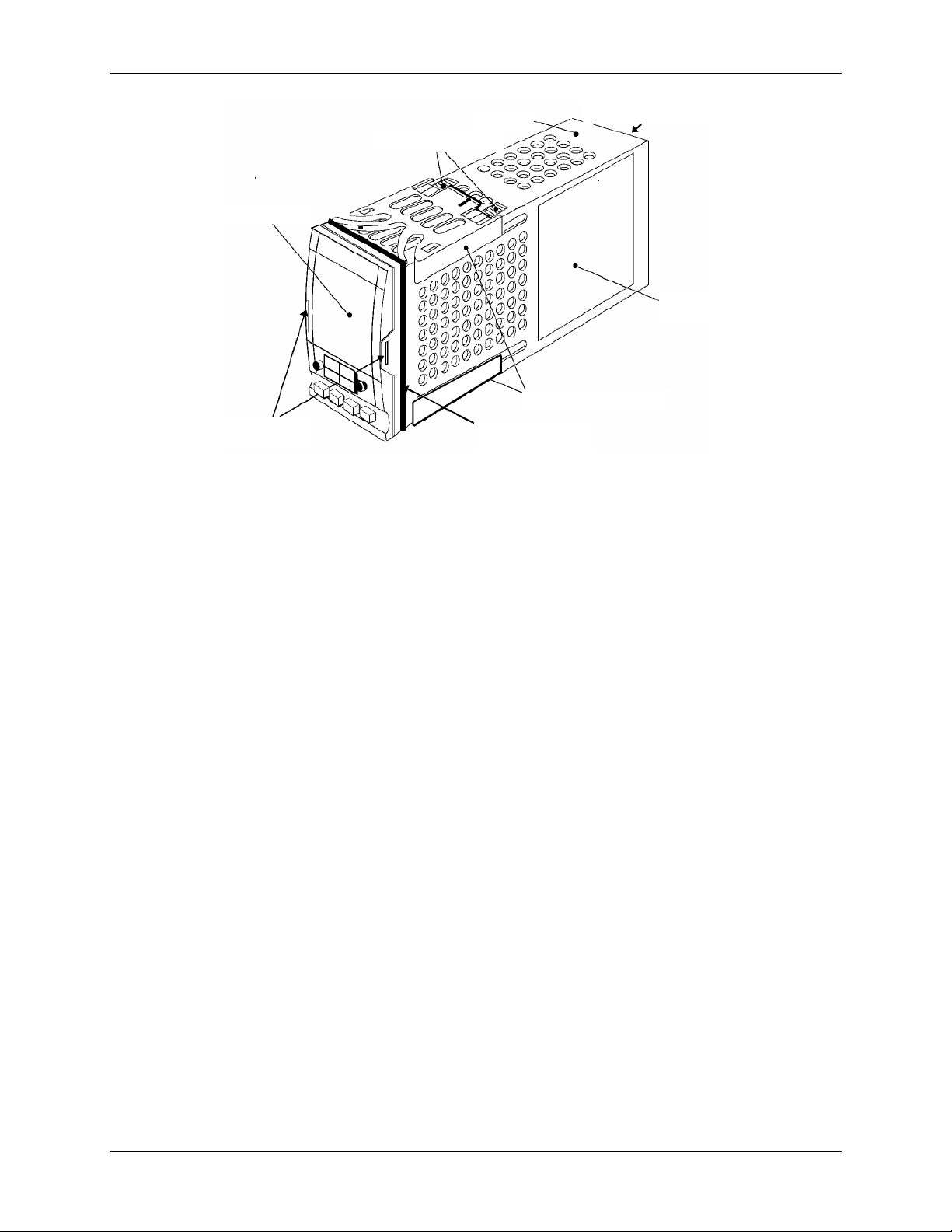
Electronic Control System (ECS) and Type CXT-E Valve
TERMINAL COVERS
SLEEVE
LABEL
PANEL RETAINING
CLIPS
PANEL SEALING
GASKET
LATCHING
EARS
DISPLAY
RATCHETS
8. CORRECTIVE MAINTENANCE
Figure 8-7. Temperature Controller Installation
4) Close and secure Control Box front door.
8.3.4 Over-Temperature Switch and Temperature Indicator Replacement
The Over-Temperature Switch and Temperature Indicators are actually identical devices,
however they perform different functions. One Over-Temperature Switch is provided in each
Control Box for both Steam-to-Water and Water-to-Water applications. As the name implies, the
Over-Temperature Switch, performs a switching function and generates an alarm when the
preset temperature limit is exceeded. However, the Temperature Indicators, used only with
Water-to-Water Heat Exchangers, are Indicator-Only devices and are not wired to perform any
switching functions. The locations of t he Over-Temperature Switch and Temperature I ndicators
for Steam-to-Water and Water-to-Water applications are shown in Figure 1-3. Removal and
replacement for each device are performed using the following identical steps:
1) Open the Control Box door to locate the Temperature Switch/Indicator assembly.
2) Loosen the captive screw on upper par t of recessed panel behind the door and open the
swing-down panel to access the terminal wiring connections and retaining clips of the
Temperature Switch/Indicator assembly (Figure 8-8a).
3) Loosen the terminal wiring connection screws on the rear of the Temperature
Switch/Indicator assembly and disconnect the wires.
The Type J Thermocouples are wired with the Red lead Negative (-)
and the White lead Positive (+).
4) To remove the Temperature Switch/Indicator assembly, push in tab of each of two side
retaining clips (Figure 8-8b), slide toward rear and remove.
NOTE:
VD2: 02/28/14 AERCO International, Inc. • 100 Oritani Dr. • Blauvelt, New York 10913 • Phone: 800-526-0288 Page 63 of 82
AC-105 OMM-0003_0D
Page 64

Electronic Control System (ECS) and Type CXT-E Valve
To uninstall
9. RECOMMENDED SPARE PARTS
Figure 8-8a. Over-Temperatu re Swi tch & Tem per atu re I nd icat or
push tab to release clip
retainer. Slide clip back
and off. Remove
assembly through front
panel.
Figure 8-8b. Over-Temperature Switch & Temperature Indicator Installation
5) If the replaced unit is an Over-Temperature Switch, set the desired over-temperature alarm
limit using the Adjustment procedures in Section 3. No adjustments are required following
replacement of the Boiler Water IN or Boiler Water OUT Temperature Indicator on water-towater heaters.
6) Following adjustment (if necessary), raise and secure the swing-down panel. Close and
secure the Control Box door. If adjustments or replacements have been made, refer to the
Adjustment procedures in Section 3 and repeat as necessary.
8.3.5 DC Power Supply Replacement
The DC Power Supply is mounted on the left interior wall of the Control Box (see Figure 8-9,
View A - A). Replacement is accomplished as follows:
1) Open the Control Box door and loosen the captive screw on the recessed panel behind the
door.
2) Open the swing-down panel and locate the DC Power Supply on the left interior wall of t he
Control Box (Figure 8-9, View A - A).
3) Disconnect the AC input power connector near the bottom of the Power Supply and the DC
output connector near the top.
4) Remove the four hex standoffs and lock washers securing the DC Power Supply to the
studs on the interior side wall of the Control Box. Completely remove the DC Power Supply
from the Control Box.
5) Replacement is accomplished by simply reversing the previous steps.
Page 64 of 82 AERCO International, Inc. • 100 Oritani Dr. • Blauvelt, New York 10913 • Phone: 800-526-0288 VD2: 02/28/14
OMM-0003_0D AC-105
Page 65

Electronic Control System (ECS) and Type CXT-E Valve
8. CORRECTIVE MAINTENANCE
8.3.6 DC Voltage Regulator Replacement
The DC Voltage Regulator is mounted on the bottom interior surface of the Control Box chassis.
Replacement is accomplished as follows:
1) Open the Control Box door and loosen the captive screw on the recessed panel behind the
door.
2) Open the swing-down panel and locate the DC Voltage Regulator on the bottom of the
chassis interior (Figure 8-9, View D – D).
3) Disconnect the wiring connector plug shown in Figure 8-9, View D – D.
4) Remove the four hex nuts and lock washers securing the Regulator to the studs on the
bottom of the chassis. Completely remove the DC Voltage Regulator from the Control Box.
5) DC Voltage Regulator replacement is accomplished by reversing the previous steps.
VD2: 02/28/14 AERCO International, Inc. • 100 Oritani Dr. • Blauvelt, New York 10913 • Phone: 800-526-0288 Page 65 of 82
AC-105 OMM-0003_0D
Page 66

Electronic Control System (ECS) and Type CXT-E Valve
69012-2
SIDE VIEW - TYPICAL
2408
AUTO
MAN
HOLD
RUN
OVER TEMPERATURE SWITCH
BOILER WATER TEMP
IN
OUT
TEMP CONTROLLER
POWER ON
OFF
69012-1
2408
AUTO
MAN
HOLD
RUN
OVER TEMP SWITCH
PT.NO.
PT.NO.
WATER HEATER
E-PLUS
WATER HEATER
B-PLUS
TEMP CONTROLLER
A
A
B
B
D
D
E
E
1
3
4
4
2
3
5
C
C
NOTE:
SEE SHEET 5 FOR
PARTS LIST
POWER IN
6
7
OR
12
12
13
9. RECOMMENDED SPARE PARTS
Figure 8-9. ECS Control Box Assembly Component Locations (Sheet 1 of 6)
Page 66 of 82 AERCO International, Inc. • 100 Oritani Dr. • Blauvelt, New York 10913 • Phone: 800-526-0288 VD2: 02/28/14
OMM-0003_0D AC-105
Page 67

INTERIOR LEFT WALL
- +
INTERIOR RIGHT WALL
VIEW A -A
VIEW B -B
6
POWER
SUPPLY
AC INPUT
CONNECTOR
DC OUTPUT
CONNECTOR
5
AC POWER
ON/OFF
SWITCH
2
1A
1
AC POWER
CABLE
CUTOUT
15
14
AC-105 Electronic Control System (ECS) and Type CXT-E Valve
OMM-0003_0D User Manual CORRECTIVE MAINTENANCE
Figure 8-9. ECS Control Box Assembly Component Locations (Sheet 2 of 6)
VD2: 02/28/14 AERCO International, Inc. • 100 Oritani Dr. • Blauvelt, New York 10913 • Phone: 800-526-0288 Page 67 of 82
AC-105 OMM-0003_0D
Page 68

NOTE:
SEE APPENDIX B FOR
WIRING CONNECTIONS
VIEW C - C
INTERIOR BACK WALL
9
TERMINAL
BLOCK TB-1
17
16
16
7
AC POWER
TERMINAL
BLOCK TB-2
REAR
INTERIOR BOTTOM SURFACE
VIEW D - D
8
VOLTAGE
REGULATOR
INPUT/OUTPUT
CONNECTOR
TB-2
21
22
14
20
15
16
17
19
18
Electronic Control System (ECS) and Type CXT-E Valve
9. RECOMMENDED SPARE PARTS
Figure 8-9. ECS Control Box Assembly Component Locations (Sheet 3 of 6)
Page 68 of 82 AERCO International, Inc. • 100 Oritani Dr. • Blauvelt, New York 10913 • Phone: 800-526-0288 VD2: 02/28/14
OMM-0003_0D AC-105
Page 69

AC-105 Electronic Control System (ECS) and Type CXT-E Valve
OVERTEMP SWITCH
7 8 9 10 11
1 2
TEMPERATURE
CONTROLLER
L
N
G
V+
V-
1A
1B
3A
3D
TEMPERATURE
CONTROLLER
L
N
G
V+
V-
1A
1B
3A
3D
OVERTEMP SWITCH
7 8 9 10 11
1 2
7 8 9 10 11
1 2
7 8 9 10 11
1 2
4
3
VIEW E – E
(CONTROL BOX 69011-1)
4
4
4
3
PANEL REAR
PANEL REAR
BOILER WATER TEMP
IN
OUT
VIEW E – E (CONTROL BOX 69011-2)
NOTE:
SEE APPENDIX B FOR WIRING CONNECTIONS
OMM-0003_0D User Manual CORRECTIVE MAINTENANCE
Figure 8-9. ECS Control Box Assembly Component Locations (Sheet 4 of 6)
VD2: 02/28/14 AERCO International, Inc. • 100 Oritani Dr. • Blauvelt, New York 10913 • Phone: 800-526-0288 Page 69 of 82
AC-105 OMM-0003_0D
Page 70

Electronic Control System (ECS) and Type CXT-E Valve
CONTROL BOX ASSY.
69012-1
WATER)
69012-2
WATER)
1 1
1 1
1 1
1 1
17 4 4
56012
HEX NUT, #8-32
18 2 2
56011
HEX NUT, #6-32
19 2 2
53012
LOCK WASHER, #6
20 4 4
56010
HEX NUT, #4-40
21 2 2
62002
STRAIN RELIEF
22 1 1
62003
PLUG
THE FOLLOWING ITEMS ARE NOT ILLUSTRATED IN FIGURE 8-9:
23
1
69014-1
CONTROL BOX CONNECTORS
24 1
69014-2
CONTROL BOX CONNECTORS
25 1 1
63007
AC WIRE HARNESS
26
1
63008-1
CONTROL BOX CONN. WIRE HARNESS
27 1
63008-2
CONTROL BOX CONN. WIRE HARNESS
9. RECOMMENDED SPARE PARTS
ECS Control Box Assembly Parts List
(STEAM/
ITEM QTY QTY PAR T NO. DESCRIPTION
1 1
2
3 1 1
4 1 3 64007 OVER-TEMP SWITCH/TEMP INDICATOR
5 1 1 60003 ON/OFF SWITCH
6 1
7
8
9
10
11
(WATER/
1 69011-2 CONTROL BOX (WATER/WATER)
1 63009-2
69011-1 CONTROL BOX (STEAM/WATER)
SEE TABLE
A
63009-1
65006
65007
64011
65008
TEMPERATURE CONTROLLER
CONTROL BOX, EXTERNAL HARNESS
(S/W)
CONTROL BOX, EXTERNAL HARNESS
(W/W)
POWER SUPPLY
TERMINAL BLOCK, 4-POSITION (TB-2)
VOLTAGE REGULATOR
TERMINAL BLOCK, 20-POSITION (TB-1)
12 AS REQ’D AS REQ’D
13 1 1 62004 PLUG
14 8 8 53011 LOCK WASHER, #4
15 12 12 65010 STANDOFF
16 4 4 53010 LOCK WASHER, #8
SEE TABLE
B
COMMUNICATIONS BOARD
Figure 8-9. ECS Control Box Assembly Component Locations (Sheet 5 of 6)
Page 70 of 82 AERCO International, Inc. • 100 Oritani Dr. • Blauvelt, New York 10913 • Phone: 800-526-0288 VD2: 02/28/14
OMM-0003_0D AC-105
Page 71

AC-105 Electronic Control System (ECS) and Type CXT-E Valve
PART NUMBER
DESCRIPTION
OMM-0003_0D User Manual CORRECTIVE MAINTENANCE
Table A – Programmed Temperature Controllers
PART NUMBER PROGRAMMED TEMPERATURE CONTROLLER USE D ON:
64028-1 HELITHERM HEATER MODELS: A+, B+, B+ II, E+
*64028-2 DOUBLE-WALL HEATER MODELS: SWDW24, SWDW45
64028-3 DOUBLE-WALL HEATER MODEL: WWDW24
64028-4 DOUBLE-WALL HEATER MODEL: WWDW45
*64028-5 DOUBLE-WALL HEATER MODEL: SWDW6 8
65028-6 DOUBLE-WALL HEATER MODEL: WWDW68
*Refer to HE-111 for SWDW Systems built after Nov. 1, 2009. These systems
use a thermocouple for feed-forward instead of a flowmeter.
Table B – Communications Board Options
64009-1 RS232 COMMUNICATIONS BO ARD
64009-2 RS485 COMMUNICATIONS BO ARD
Figure 8-9. ECS Control Box Assembly Component Locations (Sheet 6 of 6)
VD2: 02/28/14 AERCO International, Inc. • 100 Oritani Dr. • Blauvelt, New York 10913 • Phone: 800-526-0288 Page 71 of 82
AC-105 OMM-0003_0D
Page 72

Electronic Control System (ECS) and Type CXT-E Valve
9. RECOMMENDED SPARE PARTS
(This page intentionally blank)
Page 72 of 82 AERCO International, Inc. • 100 Oritani Dr. • Blauvelt, New York 10913 • Phone: 800-526-0288 VD2: 02/28/14
OMM-0003_0D AC-105
Page 73

Electronic Control System (ECS) and Type CXT-E Valve
RECOMMENDED
QUANTITY
PAR T NAME
FIGURE 8-1 OR 8-2
ITEM NUMBER
2
Valve Seat 7 2
Valve Top Gasket
13
2
Packing Assembly
20
2
Seat Cage Gasket
24
2
Gasket (Linkage)
29
2
Lower Pilot Seat*
33*
RECOMMENDED
QUANTITY
PAR T NAME
PART
NUMBER
1
Dual Thermocouple (Tc) - Type J
with compression fitting
99042-2
1
Single Thermocouple (Tc) – Type J
(Water-to-Water ONLY)
99042-1
1
Flow Sensor Impeller Replacement
Kit
24051-1
1
Flow Sensor Cover Replacement Kit
(Clear Polycarbonate Cover)
24051-2
*
Flow Sensor Cover Replacement Kit
(Stainless Steel Cover)
24051-3
9. RECOMMENDED SPARE PARTS
9. RECOMMENDED SPARE PARTS
9.1 CXT-E CONTROL VALVE RECOMMENDED S PARE PARTS
AERCO recommends that the CXT-E Spare Parts listed in Table 9-1 be kept on hand for
maintenance replacement purposes The Recommended Quantity for the parts shown apply to
each 1 to 5 Control Valves of the same size.
NOTE:
For Part Numbers of the items listed below, refer to Figure 8-1 for
Control Valve sizes ranging from 1.00” to 2.00”. Refer to Figure 8-2
for 2.50” to 4.00” Control Valve sizes.
Table 9-1. Recommended Spare Parts For CXT-E Control Valves (1.00” – 4.00”)
* Used on Control Valve sizes ranging from 1.00” to 2.00” ONLY
9.2 ELECTRONIC CONTROL SYSTEM RECOMMENDED SPARE PARTS
AERCO recommends that the ECS Spare Parts listed in Table 9-2 be kept on hand for
maintenance replacement purposes.
Table 9-2. Recommended Spare Parts For Electronic Control System (ECS)
with compression fitting
VD2: 02/28/14 AERCO International, Inc. • 100 Oritani Dr. • Blauvelt, New York 10913 • Phone: 800-526-0288 Page 73 of 82
AC-105 OMM-0003_0D
Page 74

Electronic Control System (ECS) and Type CXT-E Valve
9. RECOMMENDED SPARE PARTS
* Part No. 24051-3 is only used for applications where the water pressure is
greater than 200 psig.
Page 74 of 82 AERCO International, Inc. • 100 Oritani Dr. • Blauvelt, New York 10913 • Phone: 800-526-0288 VD2: 02/28/14
OMM-0003_0D AC-105
Page 75

MODBUS
Data Addr
(BAS)
MODBUS
(Hex.)
MODBUS
(Dec.)
Ref. 1
Guide
140°F, Address to read
value
Read
Only
Setpoint
internal)
change value
30002
0x0001 1
Top
Value
Outlet Temp
Same value as front
display
Read
Only
5-3 30134
0x0085 133
LoGH
Peak Temp
Read
Only
5-15 30136
0x0087 135
LoGA
Average
Temp
Read
Only
5-15 30135
0x0086 134
LoGL Low Temp
Read
Only
5-15
30014 (set)
0x000D
13 (set)
1 = alarm)
30015 (set)
0x004A
14 (set)
1= alarm)
Sensor input to
display temp.
Only
Read
Only 5-14
Remote Input
Parameter
Electronic Control System (ECS) and Type CXT-E Valve
APPENDIX A
APPENDIX A
TEMPERATURE CONTROLLER INFORMATION
MODBUS Communication information (Eurotherm 2408)
NOTE:
The Eurotherm 2400 Controller supports the MODBUS RTU mode of
transmission. The default settings are as follows: 9600 Baud Rate,
one start bit, eight data bits, one stop bit, & no parity bit.
IMPORTANT NOTE:
All Modbus addresses specified in this manual are written generically
in decimal format. However, many Building Automation Systems
utilize another form of addressing where: 40001 is added to the
generic address f or a Holding Register address And 30001 is added
to the generic address for an Input Register address.
Check the addressing scheme being used by the BAS interfaced to
the XPC Gateway.
EUROTHERM SERIES 2400 CONTROLLER MODBUS POINTS
Data Addr
Data Addr
Menu
Item
Menu Item
Description
Units &
Range
Default/Comments
Register
Type
Comm.
30006 0x0005 5 w.SP Setpoint 40-205°F
40025
30075
(status)
30075
(status)
30259
30290
0x0018
0x004A
0x000E
0x0102
0x0121
24
74 (status,
0 = safe
74 (status,
0 = safe
258
289
SP 1
AL 1
AL 2
(FSH)
Sbr
Li 1
(local or
Over Temp
Alarm
Full Scale
High Alarm
Feedback
Sensor Break
Feedback
Sensor Temp 40-180°F
40-205°F 140°F, Address to
40-205°F
40-205°F Resets on Power Loss
40-205°F Resets on Power Loss
40-205°F Resets on Power Loss
40-205°F
205°F
Status:
0:Good
1:Failed
20°F above setpoint;
Alarm Type 17:
Deviation High
205 ° F
Alarm Type 2: Full Scale
High
Denotes Feedback
Sensor Failure/Open
Circuit
controller, same as
Write 5-11
Read
Only
Read
Only
Read
Only
Read
5-20
5-20
5-18
5-14
5-4
5-7
5-7
VD2: 02/28/14 AERCO International, Inc. • 100 Oritani Dr. • Blauvelt, New York 10913 • Phone: 800-526-0288 Page 75 of 82
AC-105 OMM-0003_0D
30291 0x0122 290 Li 2 Flow GPM
30004 0x0003 3 OP
40027 0x001A 26 RI
Control
Output Signal
Comms
Access
%
40-205°F
Correlates to valve
position
MODBUS Remote
Setpoint Address
Read
Only
Write 5-17
5-4
Page 76

Electronic Control System (ECS) and Type CXT-E Valve
DISPLAY
MEANING
_FSL*
PV Full Scale Low Alarm.
_FSH*
PV Full Scale High Alarm.
_dEu*
PV Deviation Band Alarm
_dHi*
PV Deviation Hig h A lar m
_dLo*
PV Deviation Low Alarm
DISPLAY
MEANING
WHAT TO DO`
This fault will automaticall y tak e you into
frequently, contact your supplier
Sensor Break: Input sensor is
out of range.
Hardware Error
wrong type, missing, or faulty.
Check to ensure that the correct items
procedure to clear the Hardware Error.
No I/O
are installed
This error message normally occurs
installing any of the required I/O modules.
Remote input failure.
shorted
LLLL
Out of range low reading
Check the value of the input
HHHH
Out of range high reading
Check the value of the input
APPENDIX A
REFERENCE DOCUMENTS for MODBUS Points information: (www.eurotherm.com)
• Eurotherm 2000 Series Communications Handbook, # HA026230
• Eurotherm 2404/2408 Control Setpoint Programmer Installation and Operation
Handbook, # HA025132
9.3 PROCESS ALARMS:
9.4 Eurotherm 2408 Process Alarms
9.5 DIAGNOSTIC ALARMS
9.6 Eurotherm 2408 Diagnostic Alarms
Configuration level. Check all of the
EE.Er
S.br
L.br
Hw.Er
Electrically Erasable Memory
Error: The value of an operator,
or configuration, parameter has
been corrupted.
unreliable or the input signal is
Loop Break
The feedback loop is open circuit
Indication that a module is of the
configuration parameters before
returning to Operator level. Once in
Operator level, check all of the operator
parameters before resuming normal
operation. If the fault persists, or occurs
Check that the sensor is correctly
connected
Check that the heating and cooling
circuits are working properly
are installed. See page A-4 for
no.io
rmt.F
Page 76 of 82 AERCO International, Inc. • 100 Oritani Dr. • Blauvelt, New York 10913 • Phone: 800-526-0288 VD2: 02/28/14
OMM-0003_0D AC-105
None of the expected I/O items
The remote DC input is open or
when pre-configuring a controll er withou t
Check for open or short circuit wiring on
the remote DC input.
Page 77

Electronic Control System (ECS) and Type CXT-E Valve
DISPLAY
MEANING
WHAT TO DO`
Err1
Error 1: ROM self-test fail
Return Controller for repair
Err2
Error 2: RAM self-test fail
Return Controller for repair
Err3
Error 3: Watchdog fail
Return Controller for repair
Err4
Error 4: Keyboard failure. Stuck
during power-up
Switch power off and then on, without
Err5
Error 5: Faulty internal
Check printed circuit board
cleared, return the controller for repair.
Err6
Digital filter chip faulty or loose
board inside controller
Return Controller for repair
Err7
PV ID failure
Return Controller for repair
Err8
Module 1 ID failure
Faulty or loose module, or isolation
problem
Err9
Module 2 ID failure
Faulty or loose module, or isolation
problem
ErrA
Module 3 ID failure
Faulty or loose module, or isolation
problem
dCF
DC output failure
Return Controller for repair
This error may result from no power to the
the Eurotherm controller.
APPENDIX A
Eurotherm 2408 Diagnostic Alarms (Continued)
OPEn
button or button was pressed
communication
Secondary Input Missing or
Disconnected
touching any of the controller buttons
interconnections. If the fault cannot be
flow meter (check for green power light on
rear of meter or 0-5V flowmeter signal
connections), or a disconnection of the Molex
connector between feedforwar d sensor and
9.6.1 Clearing Hardware Error (Hw.Er) Display
To clear a Hardware Error and reset the Temperature Controller, proceed as follows:
1) Simultaneously press the Page (
Controller.
2) Using the Up (▲) arrow button, change the password to “8”.
3) Simultaneously press the Page (
Temperature Controller display. The top line will display “8” and the bot tom line will display
“NO”.
4) Press the Up (▲) arrow button to toggle the display from “NO” to “YES”.
5) Simultaneously press the Page (
Temperature Controller and clear the Hardware Error.
VD2: 02/28/14 AERCO International, Inc. • 100 Oritani Dr. • Blauvelt, New York 10913 • Phone: 800-526-0288 Page 77 of 82
AC-105 OMM-0003_0D
) and Scroll ( ) buttons on the Temperature
) and Scroll ( ) buttons again and observe the
) and Scroll ( ) buttons to “Reset” the
Page 78

Electronic Control System (ECS) and Type CXT-E Valve
APPENDIX A
(This page intentionally blank)
Page 78 of 82 AERCO International, Inc. • 100 Oritani Dr. • Blauvelt, New York 10913 • Phone: 800-526-0288 VD2: 02/28/14
OMM-0003_0D AC-105
Page 79

AC POWER IN
(120/240 VAC)
ECS Wiring Diagram
1AHA1BHB1C
HC
2A
2B
1D
HE
HF
HD
3B3D3C
2D3A2C
JD
JF
JE
JBJCJA
LALBLCAAABACVI
V+
V-
+
In1
In2
NO
NC
C
+
-
WHITE
RED
120/240VAC
GREEN
FLOW SENSOR
BLACK
RED
THERMO
COUPLE
OUTLET
54312
ACTUATOR
1 2 7 8 109 11
PROBE INPUT
+
-
+24 VDC
FROM DC
POWER
SUPPLY
NC
NO
COM
THERMOCOUPLE
(OUTLET TEMP)
SOLENOID
VALVE
+
-
OVER TEMPERATURE SWITCH
COMMON
24VDC
4-20 MA
12VDC
FROM
VOLT.
REG.
TUBESIDE (IN)
THERMOCOUPLE
PROBE INPUT
1 2
+
7 8
9 10
11
TUBESIDE TEMPERATURE (IN)
PROBE INPUT
1 2 7 108 9
11
+
-
TUBESIDE TEMPERATURE (OUT)
WATER TO WATER HEAT EXCHANGER ONLY
DC POWER SUPPLY
(120VAC/
240VAC)
+V
+V
NEUTRAL
LINE
CONTROLLER
RED
WHITE
-
TUBESIDE (OUT)
THERMOCOUPLE
FLOW (0-5VDC)
+
-
L
N
ON
RESET
DIP SW.
12 VDC
FROM VOLTAGE
REGULATOR
260 V
2A RELAY
103
104
P/O TB-1
104
105
112
111
116
115
107
104
117
118
107
104
* COMM (SEE TABLE 2-1)
100
102
104
105
104
113
104
105
113
104
104
114 +
104 -
104 -
P/O TB-1
109
110
106
107
103
100
102
(FEEDBACK)
-V
-V
(OUTPUT
24 VDC)
+
-
105
+24 VDC TO
OVER TEMP. SWITCH
12 VDC
FROM VOLTAGE
REGULATOR
104
RED
WHITE
GND
+
-
WHITE
+
RED
-
1A
1
2
101
TB-2
LINE
102
NEUTRAL
102
SWITCH
GROUND
GND
+V
TO SOLENOID VALVE
100
106
104
106
114
P/O
TB-1
P/O
TB-1
VOLTAGE REGULATOR
LM 7812
+
+
-
INPUT
OUTPUT
-
105
104
107
12 VDC TO
OVER-TEMP
SWITCH
24VDC
12VDC
-V
+
-
LINE
100
P/O
TB-2
102
P/O
TB-2
102
100
LINE
NEUTRAL
P/O
TB-2
P/O
TB-1
105
104
P/O TB-1
P/O TB-1
P/O TB-1
*
*
*
-V FROM
POWER
SUPPLY
Electronic Control System (ECS) and Type CXT-E Valve
APPENDIX B
Appendix B
ECS WIRING & TERMINAL BLOCK CONNECTIONS
VD2: 02/28/14 AERCO International, Inc. • 100 Oritani Dr. • Blauvelt, New York 10913 • Phone: 800-526-0288 Page 79 of 82
AC-105 OMM-0003_0D
Page 80

Electronic Control System (ECS) and Type CXT-E Valve
103
104
110
111
112
114
106
104
104
105
105
104
107
115
116
117
118
113
109
SOLENOID
SOLENOID
FEEDBACK (TC -)
OVER-TEMP (TC +)
OVER-TEMP (TC -)
ACTUATOR (4 – 20 mA)
ACTUATOR (+24 VDC)
ACTUATOR (COM)
FLOW SENSOR (-)
FLOW SENSOR (+)
+24 VDC
DC GND
+12 VDC
TC IN (+)
TC IN (-)
TC OUT (+)
TC OUT (-)
FLOW SENSOR (SIG)
FEEDBACK (TC +)
WIRE NUMBERS
FUNCTIONS
TERMINAL BLOCK TB-1 (REAR WALL)
W/W UNITS ONLY
100
NEUTRAL
101
102
GROUND
GROUND
LINE
TERMINAL BLOCK TB-2
(BOTTOM SURFACE )
APPENDIX B
Page 80 of 82 AERCO International, Inc. • 100 Oritani Dr. • Blauvelt, New York 10913 • Phone: 800-526-0288 VD2: 02/28/14
OMM-0003_0D AC-105
Page 81

Electronic Control System (ECS) and Type CXT-E Valve
NOTES:
VD2: 02/28/14 AERCO International, Inc. • 100 Oritani Dr. • Blauvelt, New York 10913 • Phone: 800-526-0288 Page 81 of 82
AC-105 OMM-0003_0D
Page 82

Electronic Control System (ECS) and Type CXT-E Valve
Date
Description
Changed By
Change Log
11/20/2012 Rev C:
Rev D: PIR-934-35, Added notes to Fig 2-2, clarified
02/28/2014
instructions for adjusting the Over-Temperature Switch
sensor in section 3.3.3.
Chris Blair
Page 82 of 82 AERCO International, Inc. • 100 Oritani Dr. • Blauvelt, New York 10913 • Phone: 800-526-0288 VD2: 02/28/14
OMM-0003_0D AC-105
 Loading...