

Page 1
ECS Upgrade for SW Double Wall Heaters, Kits 27035, 27036, 27037
TECHNICAL INSTRUCTIONS
Technical Instruction Document TID-0142_0A
This document provides instructions for upgrading the Electronic
Control System (ECS)
numbers 27035, 27036 and 27037.
for Steam-to-Water (SW) Double Wall Heaters using kit
These instructions apply to the following Steam-To-Water (SW)
Double-Wall (DW) heater models:
This document replaces the following document (01/25/2011):
TSB-11-007_0A_SWDW_Recirculator-ECS_Upgrade
• SWDW-24
• SWDW-45
• SWDW-68
DISCLAIMER
The information contained in this manual is subject to change without notice from AERCO
International, Inc. AERCO makes no warranty of any kind with respect to this material, including,
but not limited to, implied warranties of merchantability and fitness for a particular application.
AERCO International is not liable for errors appearing in this manual, nor for incidental or
consequential damages occurring in connection with t he furnishing, performance, or use of these
materials.
AERCO Technical Support:
(Mon–Fri, 8am -5pm EST)
1 (800) 526-0288
Creation Date: 12/30/2014
12/30/2014 AERCO International, Inc. • 100 Oritani Dr. • Blauvelt, New York 10913 • Phone: 800-526-0288 Page 1 of 24
Page 2

ECS Upgrade for SW Double Wall Heaters, Kits 27035, 27036, 27037
Technical Instruction Document TID-0142_0A
1. INTRODUCTION ......................................................................................................................... 3
1.1 Safety Precautions ............................................................................................................... 3
1.2 Tools & Supplies Required ................................................................................................... 4
1.3 Upgrade Kit Contents ........................................................................................................... 4
2. EQUIPMENT ISOLATIO N AND REMOVAL PROCEDURES ...................................................... 4
2.1 Isolating Water Heater .......................................................................................................... 7
2.2 Draining Water Heater .......................................................................................................... 7
2.3 Removal Of Hot Water Outlet Piping .................................................................................... 7
2.4 Removal Of Items Connected To Heater Shell ..................................................................... 8
2.5 Installation Of ECS Components On Top Head Assembly .................................................... 8
2.5.1 Thermocouple & Circulator Installation For SWDW Heaters – Brazed Fittings ............. 8
2.5.2 Thermocouple & Circulator Installation For SWDW Heaters – Compression Fittings . 12
2.5.3 Temperature Controller Replacement ........................................................................ 13
2.5.4 Setpoint Temperature Adjustment ............................................................................. 13
2.5.5 Wiring the ECS Control Box for the Circulator and Temperature Control ................... 15
3. POST INSTALLATION CONNECTIO NS AND ADJUSTMENTS ............................................... 18
3.1 Input and Output Water Heater Connections ...................................................................... 18
3.2 Adjustments ....................................................................................................................... 18
4. APPENDICES ............................................................................................................................ 21
4.1 APPENDIX A: 8" SWDW ECS RECIRC. LOOP UPGRADE ............................................... 21
4.2 APPENDIX B: 10" SWDW ECS RECIRC. LOOP UPGRADE ............................................. 22
4.3 APPENDIX C: 12" SWDW ECS RECIRC. LOOP UPGRADE ............................................. 23
12/30/2014 AERCO International, Inc. • 100 Oritani Dr. • Blauvelt, New York 10913 • Phone: 800-526-0288 Page 2 of 24
Page 3
ECS Upgrade for SW Double Wall Heaters, Kits 27035, 27036, 27037
Technical Instruction Document TID-0142_0A
1. INTRODUCTION
This document applies to steam-to-water (SW) Double Wall (DW) heaters. It provides instructions
for upgrading an existing SWDW water heater with an ECS (Electronic Control System) system
and a flow sensor to an ECS system using a circulation pump.
These instructions must be performed by a skilled service technician capable of exercising the
necessary safety precautions when working with high temperature, pressurized steam and water
systems.
Operations and Maintenance Manual HE-111 is the required manual for SWDW models and is
available from the O&M Manuals section of the AERCO International website, www.aerco.com
The following paragraphs in this Section describe the safety precautions to be followed, the tools
and test equipment required to perform all procedures in this document and the contents of
the Upgrade Kits for all Heater Models.
1.1 Safety Precautions
Installation, maintenance and operating personnel must, at all times, observe all safety
regulations. The following warnings are general and must be given the same attention as
specific precautions included in these instructions.
FLUIDS UNDER PRESSURE MAY CAUSE INJURY TO
PERSONNEL OR DAMAGE TO EQUIPMENT WHEN RELEASED.
Shut off all incoming and outgoing steam and water stop
valves and carefully decrease all trapped pressures to zero
before performing any maintenance.
LIVE STEAM CAN CAUSE SEVERE BURNS
Never search for leakage in a live steam li ne by sight alone or
by “feel”. Use a mirror or other suitable polished object.
Always provide yourself with personal protective equipment,
(PPE) such as gloves, eye protection, dust mask, hard hat, etc.
HIGH VOLTAGE OF 120 VAC IS USED IN AERCO INDIRECT
FIRED WATER HEATERS. USE EXTREME CARE WHEN
ACCESSING CIRCUITS AND ELECTRICAL CONNECTIONS
WITHIN THE EQUIPMENT. SERIOUS PERSONAL INJURY OR
DEATH MAY OCCUR IF THIS WARNING IS NOT OBSERVED.
FOLLOW OSHA APPROVED LOCKOUT/ TAGOUT PROCDURES.
Burn permits may be required for certain installations
WARNING!
WARNING!
WARNING!
NOTICE:
requiring
braising.
12/30/2014 AERCO International, Inc. • 100 Oritani Dr. • Blauvelt, New York 10913 • Phone: 800-526-0288 Page 3 of 24
Page 4

ECS Upgrade for SW Double Wall Heaters, Kits 27035, 27036, 27037
Technical Instruction Document TID-0142_0A
1.2 Tools & Supplies Required
The following tools are required to perform the retrofit procedures specified in this document:
• Combination Wrenches: 7/16”, 9/16”, 5/8”, 13/16”, 1-1/16”, 1-1/8”, 8 mm
• Pipe Wrenches: 12”, 24”
• Plumbers tools to handle pipe sizes up to 3”
• Vise-Grip Pliers
• Flat Tip Screwdriver, 1/2” Blade
• Phillips Head Screwdriver, No. 3
• Brass Wire Brush
• Needle Nose Pliers
• Tape Measure
• Black Marker
• Loctite 565 or equivalent
• Manufactures’ installation instructions referenced in text
• Brazing equipm ent for assembling P/N 97049 (if burn permit available)
1.3 Upgrade Kit Contents
The contents of the Upgrade Kits, P/N 27035, 27036, and 27037 are included in Appendices A
through C at the end of this document.
2. EQUIPMENT ISOLATION AND REMOVAL PROCEDURES
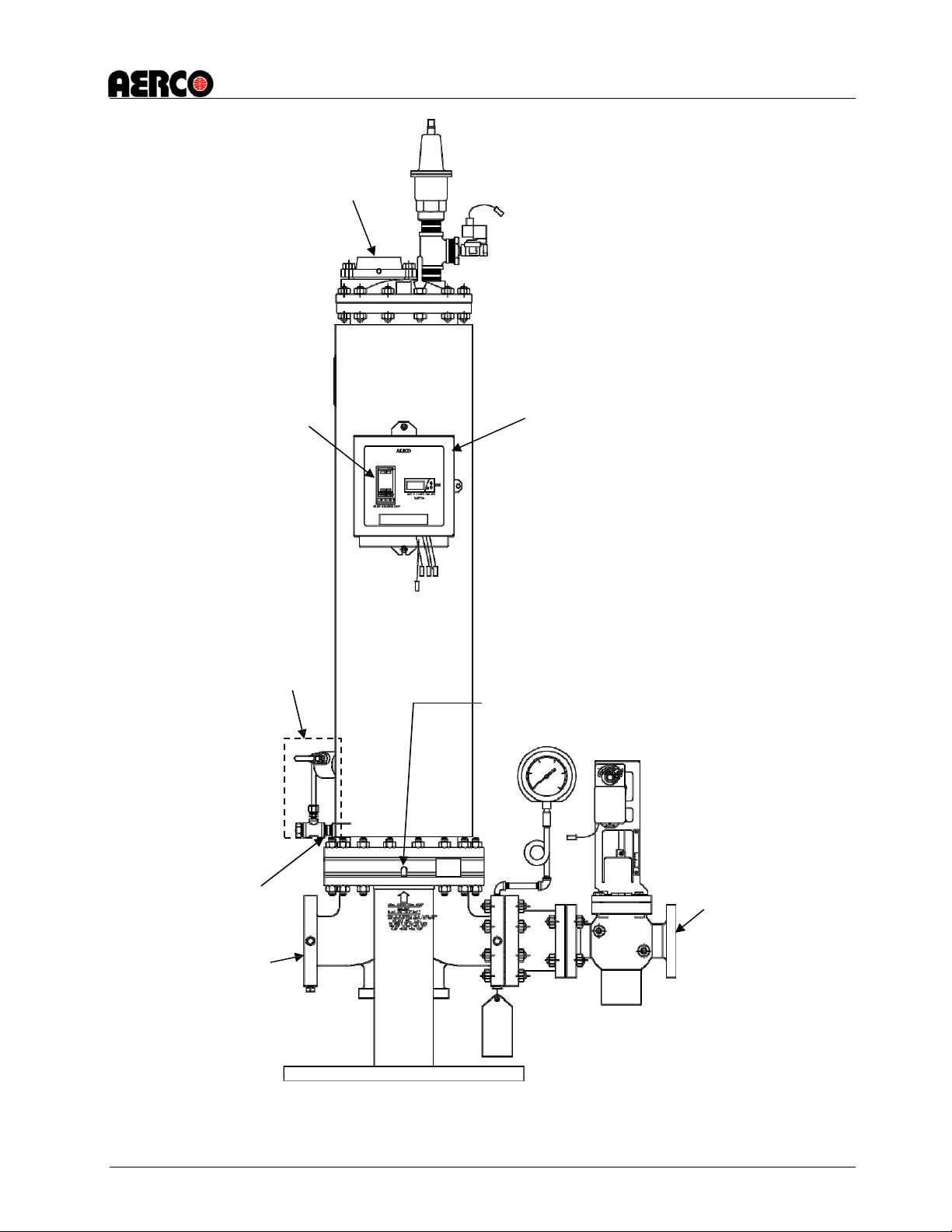
Figure 1 shows component locations for a typical Double-Wall, Model DW-24. The actual size and
location of affected components and assemblies may vary, depending on Packaged Water Heater
model and size. Refer to the applicable AERCO Heat Exchanger Manual provided with your
installation for additional details.
12/30/2014 AERCO International, Inc. • 100 Oritani Dr. • Blauvelt, New York 10913 • Phone: 800-526-0288 Page 4 of 24
Page 5
ECS Upgrade for SW Double Wall Heaters, Kits 27035, 27036, 27037
Hot Water
Outlet
Remove existing
ECS Control Box
Remove Flow Sensor
Plug vacated hole
Condensate
Outlet
Steam Inlet
Leak Detection Por t
Technical Instruction Document TID-0142_0A
temperature controller
and replace with P/N
64028-12
assembly and discard.
Install 61009-1 (Type J
Thermocouple) and 93029
(1/4” NPT x 3/16” Tube
Compression Fitting)
(Drain Hole) with 9-
22 (1/4” NPT Hex
Head Plug)
Figure 2-1:
12/30/2014 AERCO International, Inc. • 100 Oritani Dr. • Blauvelt, New York 10913 • Phone: 800-526-0288 Page 5 of 24
Before Upgrade - Double-Wall Heater Component Locations (Sheet 1 of 2)
Page 6
ECS Upgrade for SW Double Wall Heaters, Kits 27035, 27036, 27037
ECS Control Box
Plug vacated hole
Condensate
Outlet
Leak Detection Port
Orifice Disc and Snap
Cold Water Inlet
Remove Flow Sensor
Hot Water
Outlet
Technical Instruction Document TID-0142_0A
assembly and discard.
Replace with P/N 61009-1
(Type J Thermocouple
and P/N 93029 (1/4” NPT
x 3/16” Tube Compression
Fitting)
Ring Within Cold
Water Inlet Opening
with P/N 9-22 (1/4”
NPT Hex Head Plug)
Figure 2-1: Before Upgrade - Double-Wall Heater Component Locations (Sheet 2 of 2)
12/30/2014 AERCO International, Inc. • 100 Oritani Dr. • Blauvelt, New York 10913 • Phone: 800-526-0288 Page 6 of 24
Page 7

ECS Upgrade for SW Double Wall Heaters, Kits 27035, 27036, 27037
Technical Instruction Document TID-0142_0A
2.1 Isolating Water Heater
To isolate the Water Heater from all facility energy sources (steam, water, electrical power),
proceed as follows:
1. Disconnect and Lock-Out/Tag-Out external AC power supplied to the Control Box and any
other devices connected to the Heater.
2. Using a voltmeter, check to ensure that all incoming voltage readings are zero Before
continuing.
3. If the Heater is equipped with a Pneumatic Control Valve Actuator, close the valve supplying
air inlet pressure to the Pneumatic Controller.
4. Close all stop valves in the Steam Inlet and Condensate Outlet lines. On water-to-water
systems, do not rely on the Boiler Water Out Check Valve to stop the flow of water.
5. On the water-side, close the stop valves in the following order:
(a) Hot water outlet line
(b) Recirculation lin e
(c) Cold water inlet line
6. Carefully open t he Relief Valve located on the Top Head to relieve pressure in the Heater
Shell. Water should stop flowing from the valve within one minute. If water continues to flow
from the Relief Valve, one of the water stop valves is not securely closed.
2.2 Draining Water Heater
Allow the unit to cool sufficiently prior to draining the unit. When sufficiently cooled, drain as
follows:
1. After ensuring there is no pressure build-up in the Heater Shell (section. 2.1, step 6), block
open the Relief Valve in the Top Head to avoid creating a vacuum in the Heater Shell when
it is drained.
2. Open the Drain Ball Valve in the Bottom Head and allow the potable water in the Heater
Shell to drain completely. If the unit is a Water-to-Water Double-Wall Heater (WWDW-24,
WWDW-45 or WWDW-68), the Drain is located on the Shell and may either be plugged with
a 3/4” NPT Plug or equipped with a Ball Valve and additional drain piping. Remove Plug or
open Drain Ball Valve as applicable.
CAUTION
DO NOT DISCARD ANY OF THE REMOVED PARTS OR ASSEMBLIES
UNLESS IT IS SPECIFICALLY INDICATED THAT THEY WILL NO
LONGER BE USED. IT IS RECOMMENDED THAT ALL REQUIRED
ITEMS BE REMOVED AS INDICATED IN THE FOLLOWING STEPS
PRIOR TO PERFORMING ANY OF THEREPLACEMENT
PROCEDURES IN SECTION 3.
2.3 Removal of Hot Water Outlet Piping
Disconnect the union and any external piping connected to the flange in the hot water outlet
piping (located beyond the outside diameter of the Top Head).
12/30/2014 AERCO International, Inc. • 100 Oritani Dr. • Blauvelt, New York 10913 • Phone: 800-526-0288 Page 7 of 24
Page 8

ECS Upgrade for SW Double Wall Heaters, Kits 27035, 27036, 27037
Technical Instruction Document TID-0142_0A
2.4 Removal of Items Connected to Heater Shell
In order to install several new ECS components, the Flow Sensor and associated fittings/tubing
and the Cold Water Inlet Orifice Disc must be removed. Proceed as follows:
1. Disconnect any external piping connected to the Cold Water Inlet.
2. Disconnect the Flow Sensor and associated fittings/tubing and discard.
3. Take the ¼” NPT hex plug (9-22) from the kit and plug the side of the drain valve where
the Flow Sensor tubing was located.
4. Locate the Orifice Disc in the Cold Water Inlet.
5. Using a pair of pliers, disconnect the snap ring securing the Disc in the Inlet Nozzle.
6. Remove the clip and the Orifice Disc from the Inlet Nozzle and discard.
2.5 Installation of ECS Components on Top Head Assembly
The ECS components to be installed on the Top Head Assembly include:
• Cold Water Inlet
• Thermocouple and Circulator Installation
Note that brazing is preferred method of assembling P/N 970049. However, if a burn permit or
brazing equipment is not available, then compression fittings are acceptable. See sections 2.5.1
and 2.5.2.
2.5.1 Thermocouple & Circulator Installation For SWDW Heaters – Brazed Fittings NOTE: This is the preferred method if a burn permit is available.
Use Loctite™ 565 or equivalent on all threaded potable water fittings. Loctite 567 may also be
used. Refer to Figure 2-3 for proper positioning.
1. Obtain the following from the upgrade kit:
• 2” union (93326)
• 2” Nipple (90074)
• 3”/2” Reducing coupling (93325) x 2
• 3” Tee for Cold Water Inlet (22102) x1
• 1.5” x 7” Nipple (90058)
• 1.5” Flange w/ 2 3/8” x 16 bolts and nuts (59095) set hardware aside for use in Step 17.
2. Attach 2” Union to the Cold Water Inlet (Figure 2-2).
12/30/2014 AERCO International, Inc. • 100 Oritani Dr. • Blauvelt, New York 10913 • Phone: 800-526-0288 Page 8 of 24
Page 9

ECS Upgrade for SW Double Wall Heaters, Kits 27035, 27036, 27037
Technical Instruction Document TID-0142_0A
Figure 2-2: Location of Cold Water Inlet
12/30/2014 AERCO International, Inc. • 100 Oritani Dr. • Blauvelt, New York 10913 • Phone: 800-526-0288 Page 9 of 24
Page 10

ECS Upgrade for SW Double Wall Heaters, Kits 27035, 27036, 27037
22102
12614-8
Brazed 97049
Compression 97052
59095
90075 for SVVDVV24
93265
91045-45.00
Brazed 97049
Compression 97052
69101
59095
90074
93326
90058
93325
22102
93325
Technical Instruction Document TID-0142_0A
90076 for SVVDW45
90077 for SVVDW68
-- CUT AT ASSEMBLY TO SUITE --
3. Assemble remaining items as shown in Figure 2-3
12/30/2014 AERCO International, Inc. • 100 Oritani Dr. • Blauvelt, New York 10913 • Phone: 800-526-0288 Page 10 of 24
Figure 2-3. Circulator
Sub-assembly
Page 11

ECS Upgrade for SW Double Wall Heaters, Kits 27035, 27036, 27037
Technical Instruction Document TID-0142_0A
Figure 2-4: Lower Assembly, with Part Numbers
4. Attach assembly to 2” Union so that upright is perpendicular to the ground.
5. Obtain the following from kit:
• 3” Tee for Hot Water Outlet (22102) x1
• 1.5” x 11.5” Nipple (90075) for SWDW24,
• 1.5” x 12.5” Nipple (90076) for SWDW45 or
• 1.5” x 13.5” Nipple (90077) for SWDW68
• 1.5” Union (93265)
6. Attach 3” Tee to the unit’s hot water outlet flange.
7. Attach nipple to the 3” Tee
8. Attach union to nipple
9. Obtain the following from kit:
• 1.5” Street elbow (12614-8)
• 1.5” Tube x 1.5” Male NPT adapter (97049) x2
• 1.5” Copper tube (91045-45.00)
• 1.5” Flange w/ 2 3/8” x 16 bolts and nuts (59095) set hardware aside for use in Step 17
• 1.5” Taco Circulator Cartridge (69101)—for measurement purposes
10. Braise one (1) 1.5” tube x 1.5” male NPT adapter to one end of tube.
11. Attach street elbow to 1.5” male NPT
12. Check for length—Size to accommodate the installation of the pump (69101) and the flange
adaptor (59095)
13. Cut 1.5” copper tube to length
14. Braise one (1) 1.5” tube x 1.5” male NPT adapter to other end of tube.
15. Attach flange to 1.5” male NPT adapter
12/30/2014 AERCO International, Inc. • 100 Oritani Dr. • Blauvelt, New York 10913 • Phone: 800-526-0288 Page 11 of 24
Page 12

ECS Upgrade for SW Double Wall Heaters, Kits 27035, 27036, 27037
Technical Instruction Document TID-0142_0A
16. Obtain the following from kit:
• 1.5” Taco Circulator Cartridge w/ seals (69101)
• Bolts and Nuts for flanges from Step 10
17. Place pump seal in channel in flange on lower assembly.
18. Following Taco instructions included with circulator, Seat Circulator Cartridge on flange as
shown in Figure 2-3.
19. Insert bolts through lower flange and Circulator Cartridge and screw on nuts to snug
20. Place pump seal in channel on topside of Circulator Cartridge.
21. Seat tubing assembly on circulator
22. Attach tube assembly street elbow to upper union
23. Insert bolts through upper flange and Circulator Cartridge and screw on nuts to snug
24. Check for proper alignment
25. Tighten all connections and fasteners
26. Obtain the following from kit:
• Thermocouple (61009-1)
27. Screw thermocouple into threaded coupling on Cold Water Inlet
28. Connect the outlet piping to new Hot Water Outlet Tee.
29. Conduct checks laid out in section 3.1
2.5.2 Thermocouple & Circulator Installation For SWDW Heaters – Compression Fittings NOTE: This is an acceptable alternative to brazing; see Section 2.5.1.
Use Loctite™ 565 or equivalent on all threaded potable water fittings. Loctite 567 may also be
used. Refer to Figure 2-3 for proper positioning.
1. Obtain Compression fittings (97052) from upgrade kit and determine manufacturer.
2. Obtain Manufacturer’s Instruction Manual:
• Hoke/Gyralok
http://catalog.hoke.com/Asset/79002_Gyrolok_Catalog_Tech_Data.pdf
• Parker Fittings
Contact manufacturer www.parker.com/tfd
• Swagelok MS-13-151 R6
http://www.swagelok.com/downloads/WebCatalogs/EN/MS-13-151.PDF
3. Follow steps 1 through 8 in section 2.5.1 above.
4. Obtain the following from kit:
• 1.5” Street elbow (12614-8)
• 1.5” tube OD x 1.5” male NPT adapter (97052) x2
• 1.5” Copper tube (91045-45.00)
• 1.5” Flange w/ 2 3/8”-16 nuts (59095)
5. Following Manufacturer’s instructions, attach one (1) 1.5” tube ODx 1.5” male NPT adapter
to one end of tube.
12/30/2014 AERCO International, Inc. • 100 Oritani Dr. • Blauvelt, New York 10913 • Phone: 800-526-0288 Page 12 of 24
Page 13
ECS Upgrade for SW Double Wall Heaters, Kits 27035, 27036, 27037
Technical Instruction Document TID-0142_0A
6. Attach street elbow to 1.5” male NPT
7. Check for length—Size to accommodate the installation of the adaptor, the flange and the
pump.
8. Cut 1.5” copper tube to length
9. Following Manufacturer’s instructions, attach one (1) 1.5” tube OD x 1.5” male NPT adapter
to other end of tube.
10. Follow steps 15 through 29 in section 2.5.1 above.
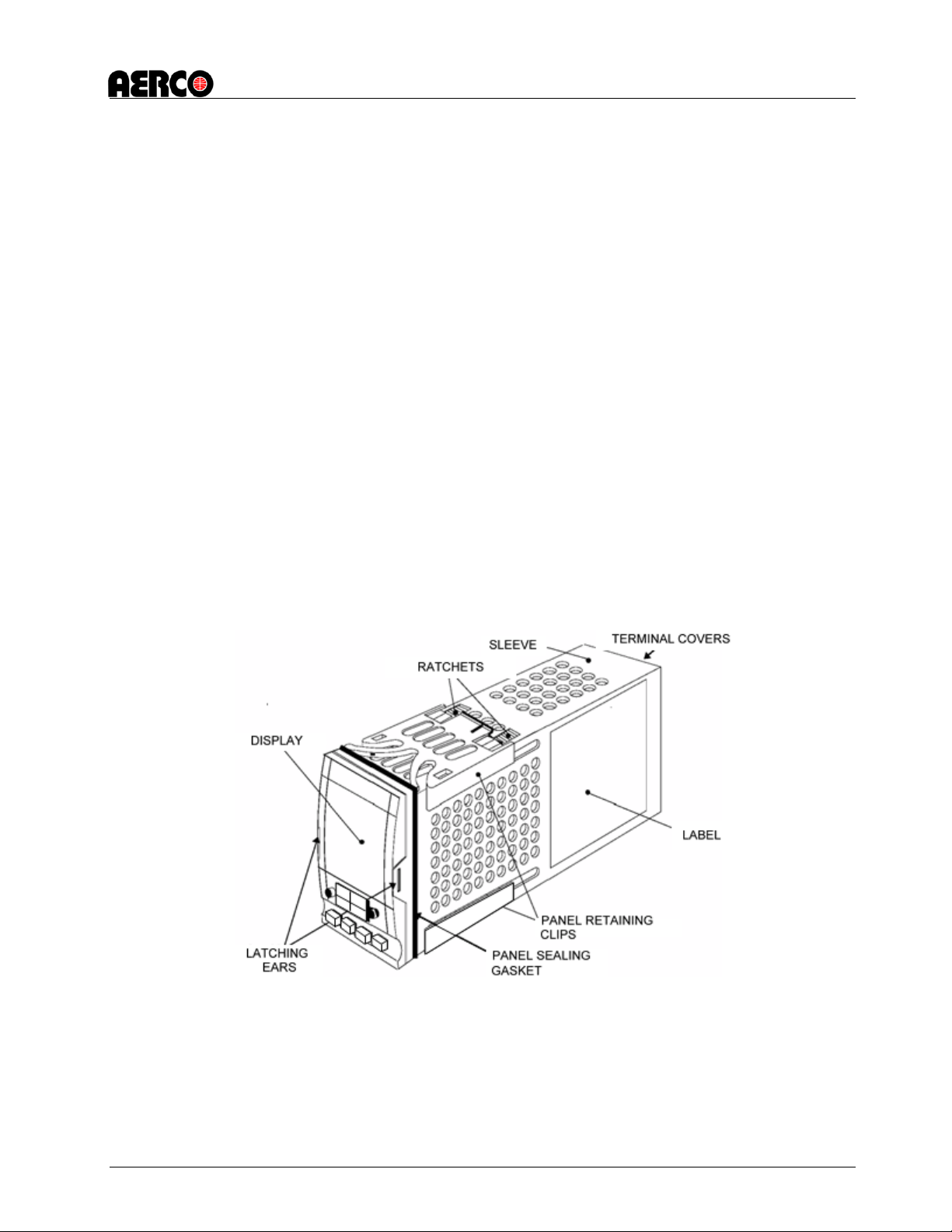
2.5.3 Temperature Controller Replacement
The Temperature Controller is located on the recessed panel behind the Control Box door as
shown in Figure 2-6. Removal and replacement is accomplished as follows:
1. Open the Control Box door to access the Temperature Controller.
2. The Temperature Controller is installed in a sleeve as shown in Figure 2-5. To unplug and
remove the
3. Controller from its sleeve, simply pry the latching ears outward and pull the Controller out of
the panel.
4. To install a replacement Temperature Controller, simply slide it into the front panel sleeve
until the latching ears click into place. Following replacement, adjust the setpoint
temperature to the required value using the adjustment procedure in Section 2.5.4.
5. Close and secure Control Box front door.
Figure 2-5: Temperature Controller Installation
2.5.4 Setpoint Temperature Adjustment
The setpoint temperature is adjusted using the controls and displays provided on the Temperature
Controller. These controls and displays are illustrated and described in Figure 2-6 and Table 2-1.
If necessary, setpoint temperature adjustment is accomplished as follows:
12/30/2014 AERCO International, Inc. • 100 Oritani Dr. • Blauvelt, New York 10913 • Phone: 800-526-0288 Page 13 of 24
Page 14

ECS Upgrade for SW Double Wall Heaters, Kits 27035, 27036, 27037
Technical Instruction Document TID-0142_0A
1. With the Control Box door open, set the ON/OFF POWER switch on the right side to the ON
position. The Temperature Controller will initiate a self-test for approximately 3 seconds.
Following the self-test, the top display will show the current outlet water temperature of the
Heater and the lower display will show the current setpoint temperature stored in memory
(default = 140°F).
2. Ensure that the Temperature Controller is set to the AUTO (automatic) mode and the AUTO
indicator is lit. If the MAN indicator is lit, press the AUTO/MAN button to toggle the mode
setting. Indicator OP1 should also be lit.
3. If the lower display does not show the desired setpoint temperature, press the ▲ or ▼
arrow button to change the display to the desired value.
4. Two seconds after the ▲ or ▼ arrow button is released, the display will blink to indicate
that the Temperature Controller has accepted and stored the displayed value.
Figure 2-6. Temperature Controller Installation
12/30/2014 AERCO International, Inc. • 100 Oritani Dr. • Blauvelt, New York 10913 • Phone: 800-526-0288 Page 14 of 24
Page 15

ECS Upgrade for SW Double Wall Heaters, Kits 27035, 27036, 27037
CONTROL or
INDICATOR
to the ECS Valve Actuator
communication is active.
MAN lights when in the manual mode.
Technical Instruction Document TID-0142_0A
Table 2-1. Temperature Controller Operating Controls, Indicators & Displays
MEANING FUNCTION
OP1
OP2
SP2
REM Remote Setpoint
Output 1 Indicator
Output 2 Indicator
Setpoint 2 Indicator
Indicator
Auto/Manual Button
and Indicators
Run/Hold Button and
Indicators
Page Button
Scroll Button
Down Button Press to decrease the value shown in the lower display
Up Button Press to increase the value shown in the lower display
OP1 lights when a 4 to 20 mA signal is being supplied
Not used for the ECS application
Not used for the ECS application
REM lights when the ECS is set up to be controlled by a
Remote (Modbus) signal. REM will also flash when Modbus
When button is pressed, the Controller is toggled between
the automatic (AUTO) and manual (MAN) modes.
AUTO lights wh en in the automatic mode.
Not used for ECS application
Press Page button to select a new list of parameters
Press Scroll button to select a new parameter in a list
NOTE:
External power at 120 to 240 VAC, 50/60 Hz is required to operate
ECS
the circuitry contained in the
are made internally by routing the power wiring through the
provided on the right side of the Control
Control Box. Power connections
cutout
Box.
2.5.5 Wiring the ECS Control Box for the Circulator and Temperature Control
To wire the Circulation Pump and Thermocouple into the ECS control box, follow these steps:
1. Loosen the captive Phillips head screw on the right front portion of the Control Box (Figure
2- to open the hinged door.
2. Swing open the door and loosen the captive Phillips head screw at the top of the recessed
panel (Figure 2-8). Swing down the panel to access terminal block TB-2 (Fig ure 2-9).
3. Circulator Electrical connections: Observe all applicable codes and safety procedures
when connecting to power supply. The motor is impedance protected, and does not require
overload protection. Either colored wire from the pump’s capacitor box can be attached to
either colored wire from the control box power supply. There is no “hot” or “common” wire
leading from the capacitor box. Typical installation would be to attach the white wire to
the white (common) power supply wire and either the yellow or blue wire to the black (hot)
power supply wire. The pump cannot run backwards.
12/30/2014 AERCO International, Inc. • 100 Oritani Dr. • Blauvelt, New York 10913 • Phone: 800-526-0288 Page 15 of 24
Page 16

ECS Upgrade for SW Double Wall Heaters, Kits 27035, 27036, 27037
Technical Instruction Document TID-0142_0A
4. Feed the external 120v 60 Hz power leads through the cutout in the right side of the ECS
Control Box.
5. Connect the Line, Neutral and Ground leads to the TB-2 terminals shown in Figure 2-9.
6. Close the swing-down panel after the power leads are secured to TB-2. Tighten the captive
screw to secure the recessed panel in the closed position.
7. Check the labels on the Control Box cables and connect them to the following components:
a. Label Connect To:
MIXED INLET TEMP THERMOCOUPLE 2-Pin Connector on
8. Fill system with domestic tap water – The system must be filled before operating the
circulator. The bearings are water lubricated and should not be allowed to operate dry.
Filling the system will result in immediate lubrication of the bearings. It is always good
practice to flush a new system of foreign matter before starting the circulator.
9. Put the controller in manual and leave it set to the zero (0) position.
10. Operate the circulator for 5 minutes immediately after flushing the system to purge
remaining air from the bearing chamber.
11. Refer to Instruction No. HE-111 for start-up procedures.
12.
Close the front door of the ECS Control Box and tighten the captive screw to secure it.
Thermocouple
Figure 2-7: Typical ECS Control Panel Front View
12/30/2014 AERCO International, Inc. • 100 Oritani Dr. • Blauvelt, New York 10913 • Phone: 800-526-0288 Page 16 of 24
Page 17

ECS Upgrade for SW Double Wall Heaters, Kits 27035, 27036, 27037
Technical Instruction Document TID-0142_0A
Figure 2-8: Typical Recessed Panel Behind Control Box Door
Figure 2-9: Typical ECS Control Box AC Power Connections
12/30/2014 AERCO International, Inc. • 100 Oritani Dr. • Blauvelt, New York 10913 • Phone: 800-526-0288 Page 17 of 24
Page 18

ECS Upgrade for SW Double Wall Heaters, Kits 27035, 27036, 27037
Technical Instruction Document TID-0142_0A
3. POST INSTALLATION CONNECTIONS AND ADJUSTMENTS
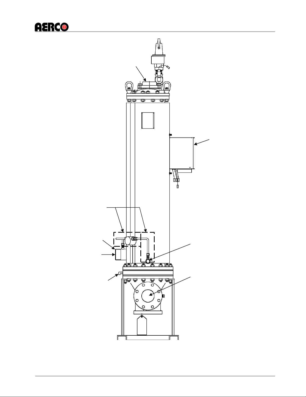
Figure 3-1 shows a typical DW-68 Double Wall S/W Heater with all ECS upgrade items
installed. Upon completion of all upgrade procedures in Section 4, the ECS upgrade heater must
be thoroughly checked to ensure that all required external connections have been made to the
modified Heater. I n addit ion, the ECS Control system adjustments must be made prior to placing
the Heater back into service.
3.1 Input and Output Water Heater Connections
The following items must be checked to ensure the proper connections have been made:
1. Drain Connection
Ensure that the side of the plugged Drain Ball Valve has been replaced and that
all external drain piping is reconnected.
2. Cold Water Inlet
Ensure that the Cold Water Inlet Flange is connected to the cold water inlet piping.
3. Steam Line
Ensure that the Steam supply line is connected to the inlet of the CXT-E Control Valve.
4. Condensate Line
Ensure it is connected to a nearby drain or condensate collection system.
5. Electrical Power
Ensure that AC power (110 to 240 volts) is connected to the ECS Control Box.
3.2 Adjustments
Prior to placing the unit into operation, the CXT-E Actuator, ECS Temperature Controller and ECS
Over-Temperature Switch must be set. The adjustment procedures for these items are provided in
Section 3 of Operation and Maintenance Manual HE-111. A copy of this manual is included in the
Upgrade Kit.
12/30/2014 AERCO International, Inc. • 100 Oritani Dr. • Blauvelt, New York 10913 • Phone: 800-526-0288 Page 18 of 24
Page 19

ECS Upgrade for SW Double Wall Heaters, Kits 27035, 27036, 27037
Technical Instruction Document TID-0142_0A
Figure 3-1. DW-68 Double Wall Water Heater With ECS Control System &
CXT-E
12/30/2014 AERCO International, Inc. • 100 Oritani Dr. • Blauvelt, New York 10913 • Phone: 800-526-0288 Page 19 of 24
Control Valve (Sheet 1 of
2)
Page 20

ECS Upgrade for SW Double Wall Heaters, Kits 27035, 27036, 27037
SIDE VIEW
Technical Instruction Document TID-0142_0A
12/30/2014 AERCO International, Inc. • 100 Oritani Dr. • Blauvelt, New York 10913 • Phone: 800-526-0288 Page 20 of 24
Figure 3-1. DW-68 Double Wall Water Heater With ECS Control System &
CXT-E Control Valve (Sheet 2 of 2)
Page 21

ECS Upgrade for SW Double Wall Heaters, Kits 27035, 27036, 27037
Assembly: 27035-1
Qty
Component
Description
1
61009-1
TYPE J THERMOCOUPLE, SINGLE ELEMENT
1
93029
COMPRESSION FITTING, ¼” NPT X 3/16” TUBE
1
64028-12
PROGRAMMED ECS TEMPERATURE CONTROLLER
1
9-22
¼” NPT HEX HEAD PLUG
UPGRADE KIT INSTRUCTIONS – 8”, 10”, AND 12” SW
DW,ECS
1
24262-1
RECIRC. LOOP UPGRADE, DW24 U-TUBE
1
12614-8
11/ 2" SS 90 DEG STREET ELBOW
2
22102
3" COLD WATER OUTLET, 8",10" & 12
2
59095
FLANGE-1 1/2" TACO FREEDOM
1
69101
CARTRIDGE CIRCULATOR
1
90058
NIPPLE 1 1/2" NPT SS 304 7" LG
1
90074
NIPPLE, 2" SCH. 40 X 2-1/2" LG
1
90075
NIPPLE, 1-1/2" NPT SCH. 40 X 11-1/2”
1
91045-45.00
COPPER TUBE, 1.5", 45" LG
1
93265
UNION, 1 1/2"NPT THREADED
2
93325
REDUCING COUPLING, 3" NPT X 2" NP
1
93326
UNION, 2" NPT THREADED
2
97049
ADAPTER, MALE PIPE, 1-1/2" TUBE X
Qty
Component
Description
1
61009-1
TYPE J THERMOCOUPLE, SINGLE ELEMENT
1
93029
COMPRESSION FITTING, ¼” NPT X 3/16” TUBE
1
64028-12
PROGRAMMED ECS TEMPERATURE CONTROLLER
1
9-22
¼” NPT HEX HEAD PLUG
1
2010-06
UPGRADE KIT INSTRUCTIONS – 8”, 10”, AND 12” SW DW,ECS
1
24262-2
RECIRC. LOOP UPGRADE, DW24 U-TUBE
BOM OF 24262-2
1
12614-8
11/ 2" SS 90 DEG STREET ELBOW
2
22102
3" COLD WATER OUTLET, 8",10" & 12
2
59095
FLANGE-1 1/2" TACO FREEDOM
1
69101
CARTRIDGE CIRCULATOR
1
90058
NIPPLE 1 1/2" NPT SS 304 7" LG
1
90074
NIPPLE, 2" SCH. 40 X 2-1/2" LG
1
90075
NIPPLE, 1-1/2" NPT SCH. 40 X 11-1/2”
1
91045-45.00
COPPER TUBE, 1.5", 45" LG
1
93265
UNION, 1 1/2"NPT THREADED
2
93325
REDUCING COUPLING, 3" NPT X 2" NP
1
93326
UNION, 2" NPT THREADED
2
97052
ADAPTER, MALE PIPE, 1-1/2" TUBE X
Technical Instruction Document TID-0142_0A
4. APPENDICES
4.1 APPENDIX A: 8" SWDW ECS RECIRCULATION LOOP UPGRADE Table A-1 Braised Fittings Construction
1 2010-06
BOM OF 24262-1
Assembly: 27035-2
Table A-2 Compression Fittings Construction
12/30/2014 AERCO International, Inc. • 100 Oritani Dr. • Blauvelt, New York 10913 • Phone: 800-526-0288 Page 21 of 24
Page 22

ECS Upgrade for SW Double Wall Heaters, Kits 27035, 27036, 27037
Qty
Component
Description
1
61009-1
TYPE J THERMOCOUPLE, SINGLE ELEMENT
1
93029
COMPRESSION FITTING, ¼” NPT X 3/16” TUBE
1
64028-12
PROGRAMMED ECS TEMPERATURE CONTROLLER
1
9-22
¼” NPT HEX HEAD PLUG
UPGRADE KIT INSTRUCTIONS – 8”, 10”, AND 12” SW
DW,ECS
1
24263-1
RECIRC. LOOP UPGRADE, DW24 U-TUBE
BOM OF 24263-1
1
12614-8
11/ 2" SS 90 DEG STREET ELBOW
2
22102
3" COLD WATER OUTLET, 8",10" & 12
2
59095
FLANGE-1 1/2" TACO FREEDOM
1
69101
CARTRIDGE CIRCULATOR
1
90058
NIPPLE 1 1/2" NPT SS 304 7" LG
1
90074
NIPPLE, 2" SCH. 40 X 2-1/2" LG
1
90076
NIPPLE, 1-1/2" NPT SCH. 40 X 12-1/2”
1
91045-45.00
COPPER TUBE, 1.5", 45" LG
1
93265
UNION, 1 1/2"NPT THREADED
2
93325
REDUCING COUPLING, 3" NPT X 2" NP
1
93326
UNION, 2" NPT THREADED
2
97049
ADAPTER, MALE PIPE, 1-1/2" TUBE X
Qty
Component
Description
1
61009-1
TYPE J THERMOCOUPLE, SINGLE ELEMENT
1
93029
COMPRESSION FITTING, ¼” NPT X 3/16” TUBE
1
64028-12
PROGRAMMED ECS TEMPERATURE CONTROLLER
1
9-22
¼” NPT HEX HEAD PLUG
1
2010-06
UPGRADE KIT INSTRUCTIONS – 8”, 10”, AND 12” SW DW,ECS
1
24263-2
RECIRC. LOOP UPGRADE, DW24 U-TUBE
BOM OF 24263-2
1
12614-8
11/ 2" SS 90 DEG STREET ELBOW
2
22102
3" COLD WATER OUTLET, 8",10" & 12
2
59095
FLANGE-1 1/2" TACO FREEDOM
1
69101
CARTRIDGE CIRCULATOR
1
90058
NIPPLE 1 1/2" NPT SS 304 7" LG
1
90074
NIPPLE, 2" SCH. 40 X 2-1/2" LG
1
90076
NIPPLE, 1-1/2" NPT SCH. 40 X 12-1/2”
1
91045-45.00
COPPER TUBE, 1.5", 45" LG
1
93265
UNION, 1 1/2"NPT THREADED
2
93325
REDUCING COUPLING, 3" NPT X 2" NP
1
93326
UNION, 2" NPT THREADED
2
97052
ADAPTER, MALE PIPE, 1-1/2" TUBE X
Technical Instruction Document TID-0142_0A
4.2 APPENDIX B: 10" SWDW ECS RECIRCULATION LOOP UPGRADE
Assembly: 27036-1
1 2010-06
Table B-1 Braised Fittings Construction
Assembly: 27036-2
Table B-2 Compression Fittings Construction
12/30/2014 AERCO International, Inc. • 100 Oritani Dr. • Blauvelt, New York 10913 • Phone: 800-526-0288 Page 22 of 24
Page 23

ECS Upgrade for SW Double Wall Heaters, Kits 27035, 27036, 27037
Qty
Component
Description
1
61009-1
TYPE J THERMOCOUPLE, SINGLE ELEMENT
1
93029
COMPRESSION FITTING, ¼” NPT X 3/16” TUBE
1
64028-12
PROGRAMMED ECS TEMPERATURE CONTROLLER
1
9-22
¼” NPT HEX HEAD PLUG
1
2010-06
UPGRADE KIT INSTRUCTIONS – 8”, 10”, AND 12” SW DW,ECS
1
24264-1
RECIRC. LOOP UPGRADE, DW24 U-TUBE
BOM OF 24264-1
1
12614-8
11/ 2" SS 90 DEG STREET ELBOW
2
22102
3" COLD WATER OUTLET, 8",10" & 12
2
59095
FLANGE-1 1/2" TACO FREEDOM
1
69101
CARTRIDGE CIRCULATOR
1
90058
NIPPLE 1 1/2" NPT SS 304 7" LG
1
90074
NIPPLE, 2" SCH. 40 X 2-1/2" LG
1
90077
NIPPLE, 1-1/2" NPT SCH. 40 X 13-1/2”
1
91045-45.00
COPPER TUBE, 1.5", 45" LG
1
93265
UNION, 1 1/2"NPT THREADED
2
93325
REDUCING COUPLING, 3" NPT X 2" NP
1
93326
UNION, 2" NPT THREADED
2
97049
ADAPTER, MALE PIPE, 1-1/2" TUBE X
Qty
Component
Description
1
61009-1
TYPE J THERMOCOUPLE, SINGLE ELEMENT
1
93029
COMPRESSION FITTING, ¼” NPT X 3/16” TUBE
1
64028-12
PROGRAMMED ECS TEMPERATURE CONTROLLER
1
9-22
¼” NPT HEX HEAD PLUG
1
2010-06
UPGRADE KIT INSTRUCTIONS – 8”, 10”, AND 12” SW DW,ECS
1
24264-2
RECIRC. LOOP UPGRADE, DW24 U-TUBE
BOM OF 24264-2
2
22102
3" COLD WATER OUTLET, 8",10" & 12
2
59095
FLANGE-1 1/2" TACO FREEDOM
1
69101
CARTRIDGE CIRCULATOR
1
90058
NIPPLE 1 1/2" NPT SS 304 7" LG
1
90074
NIPPLE, 2" SCH. 40 X 2-1/2" LG
1
90077
NIPPLE, 1-1/2" NPT SCH. 40 X 13-1/2”
1
91045-45.00
COPPER TUBE, 1.5", 45" LG
1
93265
UNION, 1 1/2"NPT THREADED
2
93325
REDUCING COUPLING, 3" NPT X 2" NP
1
93326
UNION, 2" NPT THREADED
2
97052
ADAPTER, MALE PIPE, 1-1/2" TUBE X
Technical Instruction Document TID-0142_0A
4.3 APPENDIX C: 12" SWDW ECS RECIRCULATION LOOP UPGRADE Table C-1 Braised Fittings Construction
Assembly: 27037-1
Table C-2 Compression Fittings Construction
Assembly: 27037-2
--- END ---
12/30/2014 AERCO International, Inc. • 100 Oritani Dr. • Blauvelt, New York 10913 • Phone: 800-526-0288 Page 23 of 24
Page 24

ECS Upgrade for SW Double Wall Heaters, Kits 27035, 27036, 27037
Technical Instruction Document TID-0142_0A
Change Log
Date Description Changed By
12/30/2014 Rev A: Initial release (replacement for TSB-11-007). Chris Blair
International Inc.
© AERCO International, Inc., 2014
12/30/2014 AERCO International, Inc. • 100 Oritani Dr. • Blauvelt, New York 10913 • Phone: 800-526-0288 Page 24 of 24
 Loading...