

Page 1
INTERNATIONAL, INC.
159 PARIS AVENUE • NORTHVALE, NJ 07647 • PHONE 201-768-2400
TECHNICAL SERVICE BULLETIN
Date: 04/11/07 REV. Number: 2006-02
Subject: ELECTRONIC CONTROL SYSTEM (ECS) & CONTROL
VALVE, CXT-E RETROFIT INSTRUCTIONS
Page 1 of 81
1. INTRODUCTION
This Service Bulletin provides the procedures necessary to remove an existing Control Valve Actuator
and Control Box and replace it with a new CXT-E Electronic Control Valve Actuator and Electronic
Control System (ECS). These procedures are applicable to all AERCO Indirect-Fired Water Heaters with
Control Valves ranging in size from 1 inch to 4 inches and currently equipped with pneumatic, electrohydraulic or self-contained valve actuators. In addition, this Service Bulletin applies to both steam-towater and water-to-water heaters. The types and models covered include:
• HELITHERM HEATER MODELS
• A-Plus
• B-Plus
• B-Plus II (Water Wizard)
• E-Plus
• DOUBLE-WALL HEATER MODELS:
• DW-24
• DW-45
• DW-68
These instructions must be performed by a skilled service technician capable of exercising the necessary
safety precautions when working with high temperature, pressurized steam and water systems.
The following paragraphs in this Section describe the safety precautions to be followed, the tools and test
equipment required to perform all procedures in this Service Bulletin and the contents of the Retrofit Kits
for all Heater Models.
:
1.1 SAFETY PRECAUTIONS
Installation, maintenance and operating personnel must, at all times, observe all safety regulations. The
following warnings are general and must be given the same attention as specific precautions included in
these instructions.
1
Page 2

FLUIDS UNDER PRESSURE MAY CAUSE INJURY TO
PERSONNEL OR DAMAGE TO EQUIPMENT WHEN RELEASED
Shut off all incoming and outgoing steam and water stop valves and
carefully decrease all trapped pressures to zero before performing any
maintenance.
Never search for leakage in a live steam line by sight alone or by “feel”.
Use a mirror or other suitable polished object.
Always provide yourself with personal protective equipment, (PPE) such as
gloves, eye protection, dust mask, hard hat, etc.
1.2 Tools Required
WARNING!
WARNING!
LIVE STEAM CAN CAUSE SEVERE BURNS
The following tools are required to perform the retrofit procedures specified in this Service Bulletin:
• Combination Wrenches: 7/16”, 9/16”, 5/8”, 13/16”, 1-1/16”, 1-1/8”, 8 mm
• Pipe Wrenches: 12”, 24”
• Vise-Grip Pliers
• Flat Tip Screwdriver, 1/2” Blade
• Phillips Head Screwdriver, No. 3
• Brass Wire Brush
• Needle Nose Pliers
• Tape Measure
• Black Marker
2
Page 3

1.3 Retrofit Kit Contents
The contents of the Retrofit Kits, Part No. 27004-[ ] are included in Appendices A through D of this
Bulletin. The contents included in these Appendices are as follows:
• Appendix A: Lists the Basic ECS Retrofit Kit contents for each Water Heater Model
• Appendix B: Lists Optional Items based on: valve size, flow rate, type of actuator
currently installed
• Appendix C: Lists Valve Kits required for previously installed Pneumatic and Electro -
Hydraulic Actuators
• Appendix D: Lists Valve Kits required for previously installed Self-Contained
Actuators
WARNING
HIGH VOLTAGE OF 120 VAC IS USED IN AERCO INDIRECT FIRED
WATER HEATERS. USE EXTREME CARE WHEN ACCESSING CIRCUITS
AND ELECTRICAL CONNECTIONS WITHIN THE EQUIPMENT. SERIOUS
PERSONAL INJURY OR DEATH MAY OCCUR IF THIS WARNING IS NOT
OBSERVED. FOLLOW OSHA APPROVED LOCKOUT/TAGOUT
PROCDURES.
2. EQUIPMENT ISOLATION AND REMOVAL PROCEDURES
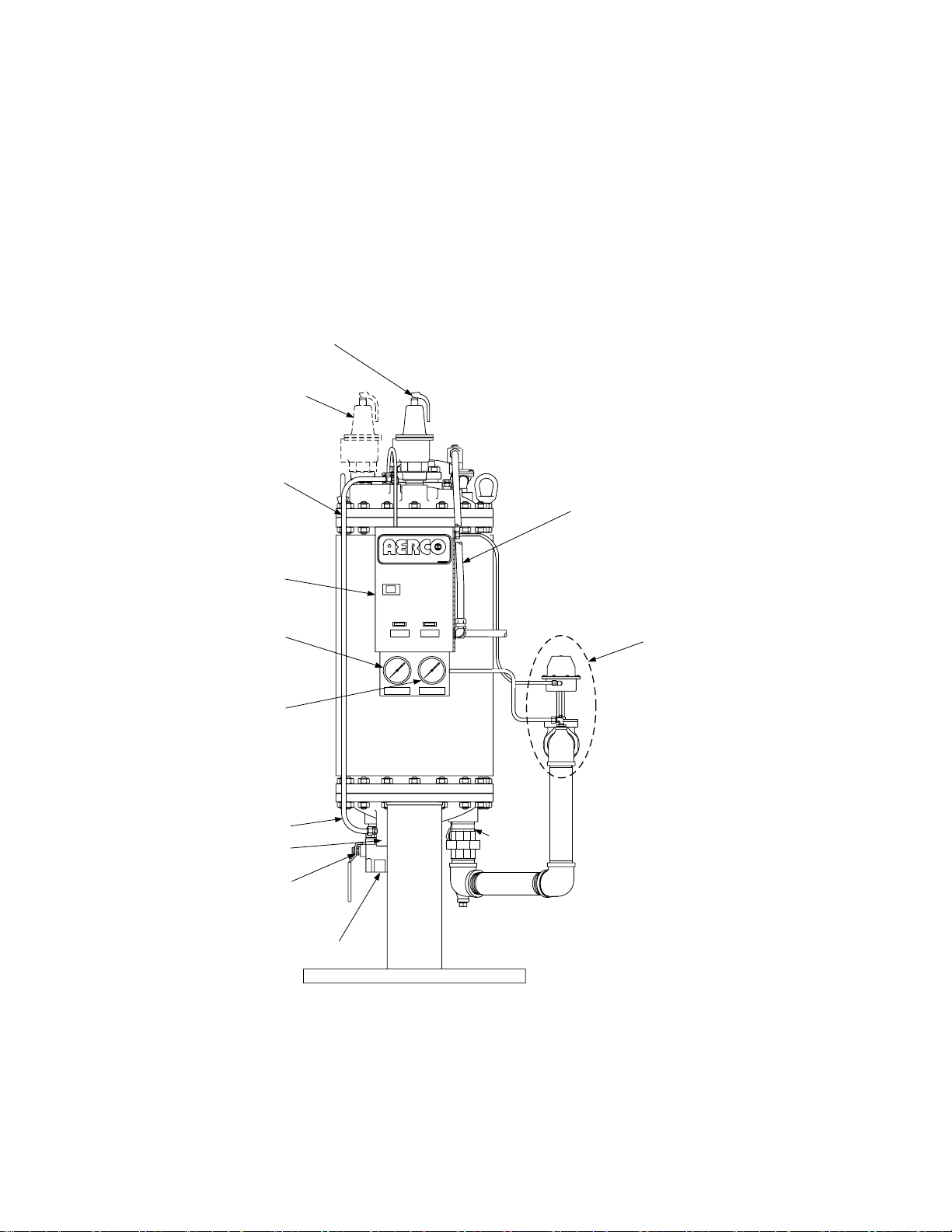
The locations of the major items to be removed from an AERCO Indirect Fired Water Heater are
shown in Figures 2-1 (Helitherm Models) and 2-2 (Double-Wall Models). These items include:
• Currently Installed Control Valve Actuator (Pneumatic, Self-Contained or Electro-Hydraulic)
• Control Box
• Top Head Solenoid Valve
• Thermal Element
• Shunt Tube
• Temperature Gauges & Capillaries
• Existing Feedback Sensor
• Load Alert Components (Except for Units With Electro-Hydraulic Valves)
In addition to the items listed above, the Drain Ball Valve (if installed) and Cold Water Inlet piping will
be temporarily disconnected to permit installation of a Flow Meter and Orifice Disk.
3
Page 4
NOTE
Figure 2-1 shows the locations of the affected components and assemblies for
a typical Helitherm, Model SW1B-Plus II Water Wizard installation. Figure 2-2
shows component locations for a typical Double-Wall, Model DW-24.
The actual size and location of affected components and assemblies may
vary, depending on Packaged Water Heater Model, size, and type of Control
Valve being retrofitted. Refer to the applicable AERCO Heat Exchanger
Manual provided with your installation for additional details.
P&T RELIEF VALVE
SECOND OPTIONAL
P&T RELIEF VALVE
SHUNT TUBE
WIRING CONDUIT TO
WATER SOLENOID VALVE
CONTROL BOX
HOT WATER OUTLET
TEMPERATURE GAUGE
COMPOUND
PRESSURE
GAUGE
SHUNT TUBE
COLD WATER IN
DRAIN BALL
VALVE
DRAIN
WATER HEATER
POWER ON TRIPPED
SHELL OUTLET
°F PSIG
STEAM PRESS.
PT.NO.128691
CONTROL VALVE*
*NOTE:
HEATER SHOWN WITH
PNEUMATIC CONTROL
VALVE. AN ELECTROHYDRAULIC OR SELFCONTAINED VALVE MAY
ALSO BE USED WITH THE
PACKAGED HEATER.
STEAM
IN
FRONT VIEW
Figure 2-1. Typical Helitherm Water Heater Component Locations (Sheet 1 of 3)
4
Page 5
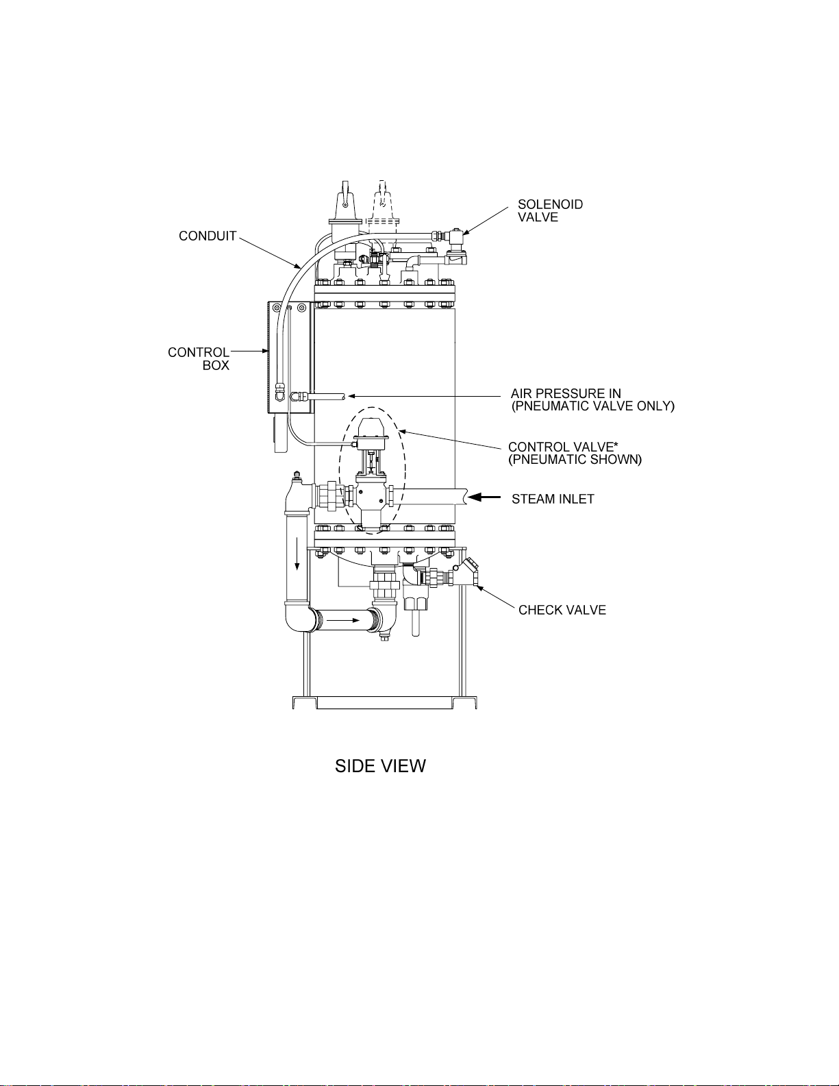
Figure 2-1. Typical Helitherm Water Heater Component Locations (Sheet 2 of 3)
5
Page 6
OUTLET
FLANGE
THERMAL
ELEMENT
P&T RELIEF
VALVE(S)
SHUNT TUBE
MOUNTING
BRACKET
(SAVE)
COLD WATER IN
LOAD ALERT**
CONTROL
BOX
TOP
SOLENOID
VALVE
FEEDBACK
SENSOR
VALVE
**NOTE:
LOAD ALERT NOT
USED WITH ELECTROHYDRAULIC CONTROL
VALVE.
SHUNT TUBE
ORIFICE DISC
SPRING RING
DRAIN VALVE
STEAM IN
CONDENSATE OUT
CONTROL
VALVE
BOTTOM
Figure 2-1. Helitherm Water Heater Component Locations (Sheet 3 of 3)
6
Page 7
SOLENOID
VALVE
S/W
COMPOUND
PRESS. GAGE
TEMP. GAGE
-OR-
W/W
PRIMARY INLET
TEMP. GAGE
MOUNTING
BRACKET
(SAVE)
HOT WATER
OUTLET
CONTROL
BOX
WATER HEATER
POWER ON TRIPPED
TUBE OUTLET
TUBE INLET
°F °F
SHELL OUTLET
°F
VALVE
PT.NO.1
2869-1
PRIMARY OUTLET
TEMP. GAGE
SECONDARY OUT.
TEMP. GAGE
3/4" PLUGGED
DRAIN
CONTROL
VALVE
CONDENSATE/BOILER
WATER OUTLET
STEAM/BOILER
WATER INLET
Figure 2-2. Double-Wall Heater Component Locations (Sheet 1 of 2)
7
Page 8
RELIEF VALVE
WATER
SOLENOID
CONTROL BOX
DOUBLE WALL
TUBE LEAK
DETECTION PORT
(NOT TO BE
PLUGGED OR
BLOCKED)
COLD WATER
INLET
ORIFICE DISC
& SPRING RING
STEAM/BOILER
WATER INLET
Figure 2-2. Double-Wall Heater Component Locations (Sheet 2 of 2)
NOTE
The majority of illustrations contained in these instructions show a typical
Water Wizard, Model SW1B Plus II Packaged Water Heater. Additional
supporting illustrations are provided only where significant differences exist
between the Water Wizard and the AERCO Heater being retrofitted. For
example: E-Plus Water-to-Water Heaters or Double-Wall (DW) Models.
8
Page 9

2.1 Isolating Water Heater
To isolate the Water Heater from all facility energy sources (steam, water, electrical power), proceed
as follows:
1. Disconnect and Lock-Out/Tag-Out external AC power supplied to the Control Box and any
other devices connected to the Heater.
2. Using a voltmeter, check to ensure that all incoming voltage readings are zero Before
continuing.
3. If the Heater is equipped with a Pneumatic Control Valve Actuator, close the valve supplying
air inlet pressure to the Pneumatic Controller.
4. Close all stop valves in the Steam Inlet and Condensate Outlet lines. On water-to-water
systems, do not rely on the Boiler Water Out Check Valve to stop the flow of water.
5. On the water-side, close the stop valves in the following order
:
(a) Hot water outlet line
(b) Recirculation line
(c) Cold water inlet line
6. Carefully open the Relief Valve located on the Top Head to relieve pressure in the Heater
Shell. Water should stop flowing from the valve within one minute. If water continues to flow
from the Relief Valve, one of the water stop valves is not securely closed.
2.2 Draining Water Heater
Allow the Water Heater to cool sufficiently prior to draining the unit. When sufficiently cooled, drain as
follows:
1. After ensuring there is no pressure build-up in the Heater Shell (para. 2.1, step 6), block open
the Relief Valve in the Top Head to avoid creating a vacuum in the Heater Shell when it is
drained.
2. Open the Drain Ball Valve in the Bottom Head and allow the potable water in the Heater Shell
to drain completely. If the unit is a Double-Wall Heater (DW-24, DW-45 or DW-68), the Drain is
located on the Shell and may either be plugged with a 3/4” NPT Plug or equipped with a Ball
Valve and additional drain piping. Remove Plug or open Drain Ball Valve as applicable.
9
Page 10

CAUTION
DO NOT DISCARD ANY OF THE REMOVED PARTS OR ASSEMBLIES
UNLESS IT IS SPECIFICALLY INDICATED THAT THEY WILL NO LONGER
BE USED. IT IS RECOMMENDED THAT ALL REQUIRED ITEMS BE
REMOVED AS INDICATED IN THE FOLLOWING STEPS PRIOR TO
PERFORMING ANY OF THEREPLACEMENT PROCEDURES IN SECTION
3.
2.3 Removal of Components on Top Head Assembly
Virtually all components currently installed in the Water Heater Top Head must be removed prior to
installing the new Electronic Control System and Electronic Valve Actuator. Refer to Figure 2-1, sheet
3 to locate the applicable Top Head components and proceed as follows:
1. Disconnect the pipe drain from the Water Solenoid Relief valve in the Top Head.
2. Disconnect the electrical leads between the Water Solenoid and the Control Box.
3. Remove the 120 VAC Water Solenoid from the nipple connecting it to the Heater Top Head.
This Solenoid will be replaced with a new 24 VDC Solenoid provided in the Retrofit Kit.
4. If a Self-Contained Control Valve is installed with the Heater, remove the Valve’s Temperature
Control Thermal Element from the Thermowell bushing in the Top Head.
5. If a Pneumatic Control Valve is installed with the Heater, remove the Thermal Element and
Bushing.
6. Remove the Dial Thermometer and Thermowell from the Top Head.
7. Remove the Aquastat Capillary and Thermowell from the Top Head.
8. Remove the Anticipator Check Valve (Load Alert) as follows:
(a) Disconnect the union or flange in the hot water outlet piping (located beyond the outside
diameter of the Top Head).
(b) Refer to Figure 2-3. Remove the four hex nuts securing the hot water Outlet Flange to the
Top Head. Remove the Flange, Flange Gasket and outlet piping connected to the Flange.
Retain the four hex nuts for reinstallation of a new Outlet Flange (Section 4).
(c) Remove the Spring Plate Assembly, Spring and Valve Plug Assembly from the Load Alert.
These removed components will no longer be used. Also, the Outlet Flange and Gasket
will be replaced with new components provided in the Retrofit Kit.
10
Page 11
OUTLET
FLANGE
FLANGE
GASKET
SPRING PLATE
ASSEMBLY
VALVE PLUG
ASSEMBLY
SPRING
HEX NUTS (4)
HOT WATER
OUTLET FLANGE
Figure 2-3. Anticipator Check Valve (Load Alert) Assembly
NOTE
For Double-Wall Heater Models (DW-24, DW-45, DW-68), the items removed
in paragraph 2.4 are located on the Shell of the Heater instead of the Bottom
Head. Therefore, refer to Figure 2-2 for Double-Wall Models.
2.4 Removal of Items Connected to Bottom Head
In order to install several new ECS components, the Drain Ball Valve must be disconnected and the
Cold Water Inlet Orifice Disc replaced. The locations of these items are shown in Figure 2-1, sheet 3.
Proceed as follows:
1. Disconnect any external piping connected to the Cold Water Inlet and Drain Ball Valve Outlet
on the Bottom Head.
2. Locate the Orifice Disc in the Cold Water Inlet (Figure 2-1, sheet 3).
3. Using a pair of pliers, disconnect the snap ring securing the Disc in the Bottom Head.
4. Remove the clip and the Orifice Disc from the Bottom Head. This Orifice Disc will be replaced
in Section 4 with a new Disc provided in the Retrofit Kit.
5. Next, temporarily remove the Drain Ball Valve from the Bottom Head (Figure 2-1, sheet 3).
Retain this Ball Valve for reinstallation in Section 4.
11
Page 12

2.5 Control Valve Actuator Removal
The Water Heater may currently be equipped with a Pneumatic, Self-Contained or Electro-Hydraulic
Control Valve Actuator. Therefore, refer to the appropriate paragraph for the type of Control Valve
Actuator currently installed.
NOTE
Following removal of the existing Control Valve Actuator, AERCO recommends that the Valve Seat and Packing be replaced using the appropriate
items included with the Retrofit Kit. If the Valve is relatively new (less than 1
year) and is currently equipped with a Pneumatic or Electro-Hydraulic
Actuator, replacement of these items may be omitted at the discretion of the
user. However, if the Valve is currently equipped with a Self-Contained
Actuator, replacement of these items is mandatory, since the Valve must be
virtually disassembled to remove the installed Actuator. A new Valve Top (plus
other items) must also be added to Self-Contained Valves before an ECS
Actuator and Linkage Assembly can be installed.
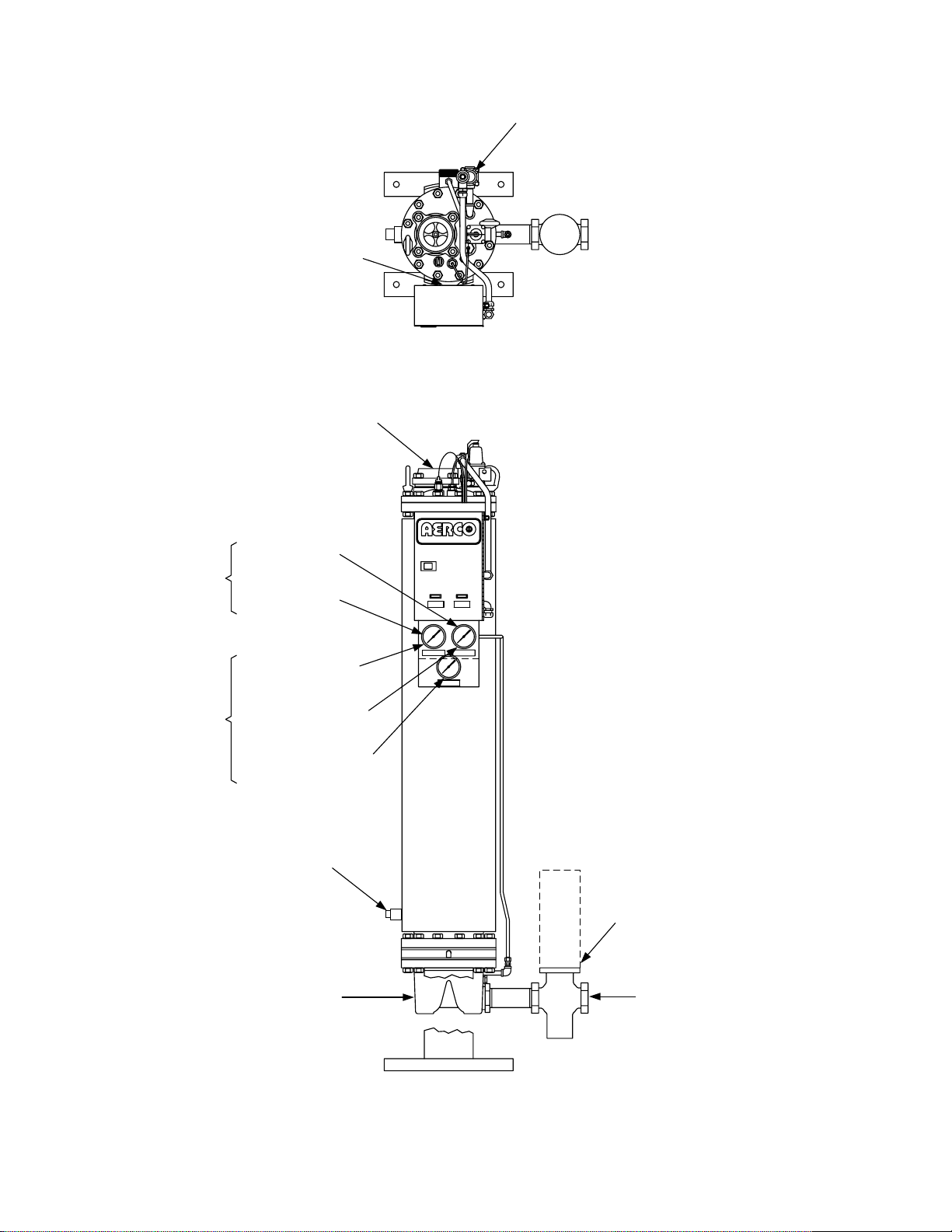
2.5.1 Pneumatic Control Valve Actuator Removal
Refer to Figure 2-4 and remove the Pneumatic Control Valve Actuator as follows:
1. Disconnect the compression fitting connecting the control air line from the Actuator Top.
2. Loosen the hex nut under the indicator disk.
3. Insert a 1/8 inch steel rod in the hole provided in the upper shaft. Hold the rod to keep the
upper shaft from turning when performing the next step.
4. Using a pair of pliers, grasp the lower shaft and rotate it counterclockwise to separate it from
the upper shaft. Use care to avoid scratching the lower shaft.
5. Remove the two 3/8-16 cap screws securing the Pneumatic Actuator to the Valve Body.
Remove the entire Actuator from the Valve.
12
Page 13
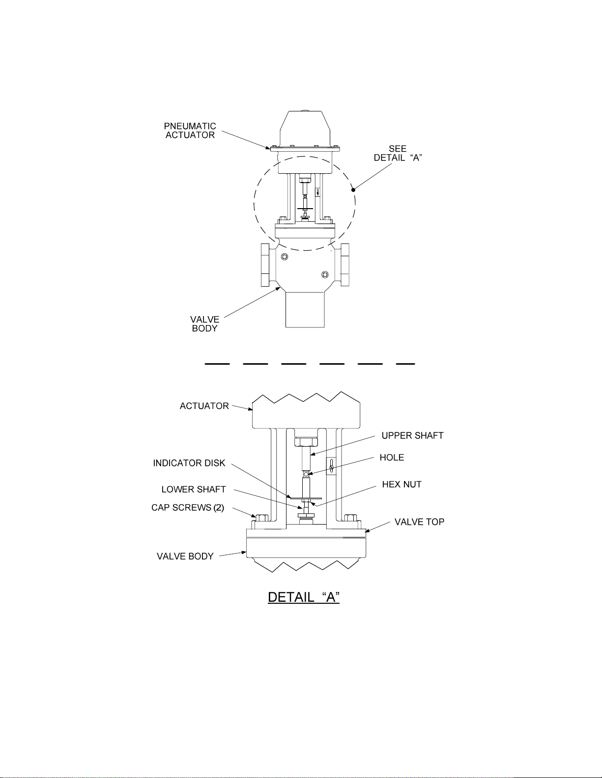
Figure 2-4. Pneumatic Control Valve Actuator Removal
13
Page 14

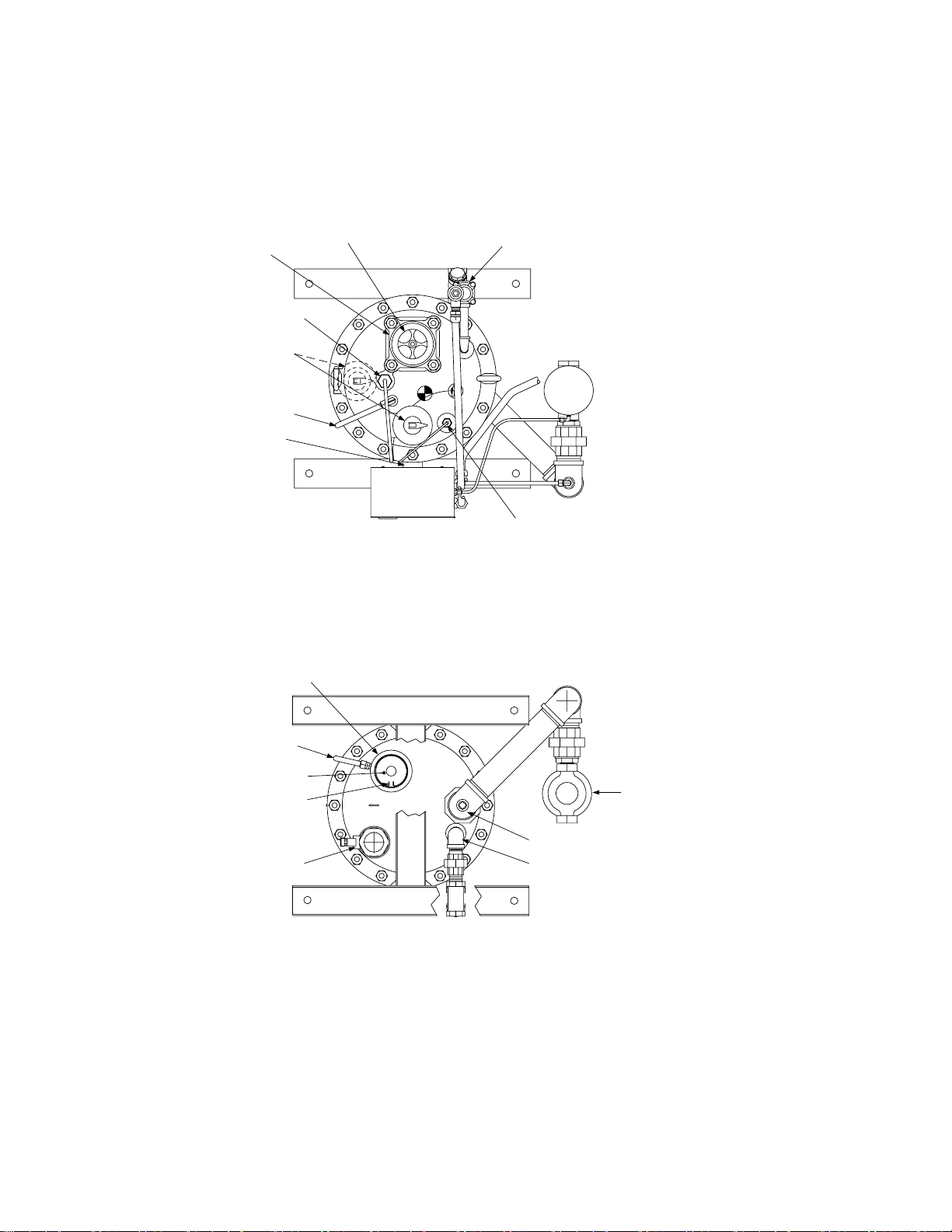
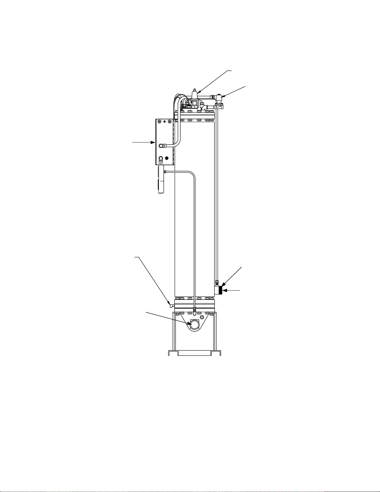
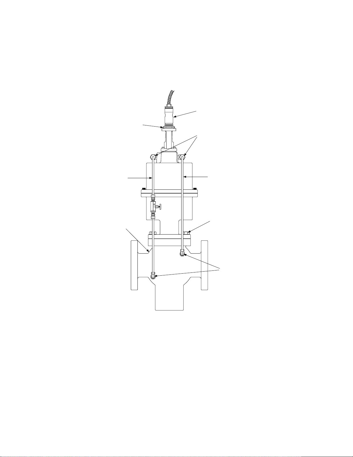
2.5.2 Electro-Hydraulic Control Valve Actuator Removal
Refer to Figure 2-5 and remove the Control Valve Actuator as follows:
1. Disconnect the electrical connectors from the Actuator.
2. Loosen the Upper Hex Nut above the Lower Crossbar shown in Figure 2-5.
3. While holding the Lower Shaft with a pair of pliers, completely remove the Upper Hex Nut.
4. Remove the four hex head bolts securing the Electro-Hydraulic Actuator to the Valve Top.
5. Lift the entire Actuator off the Valve Top. Also, remove the Actuator Gasket.
14
Page 15
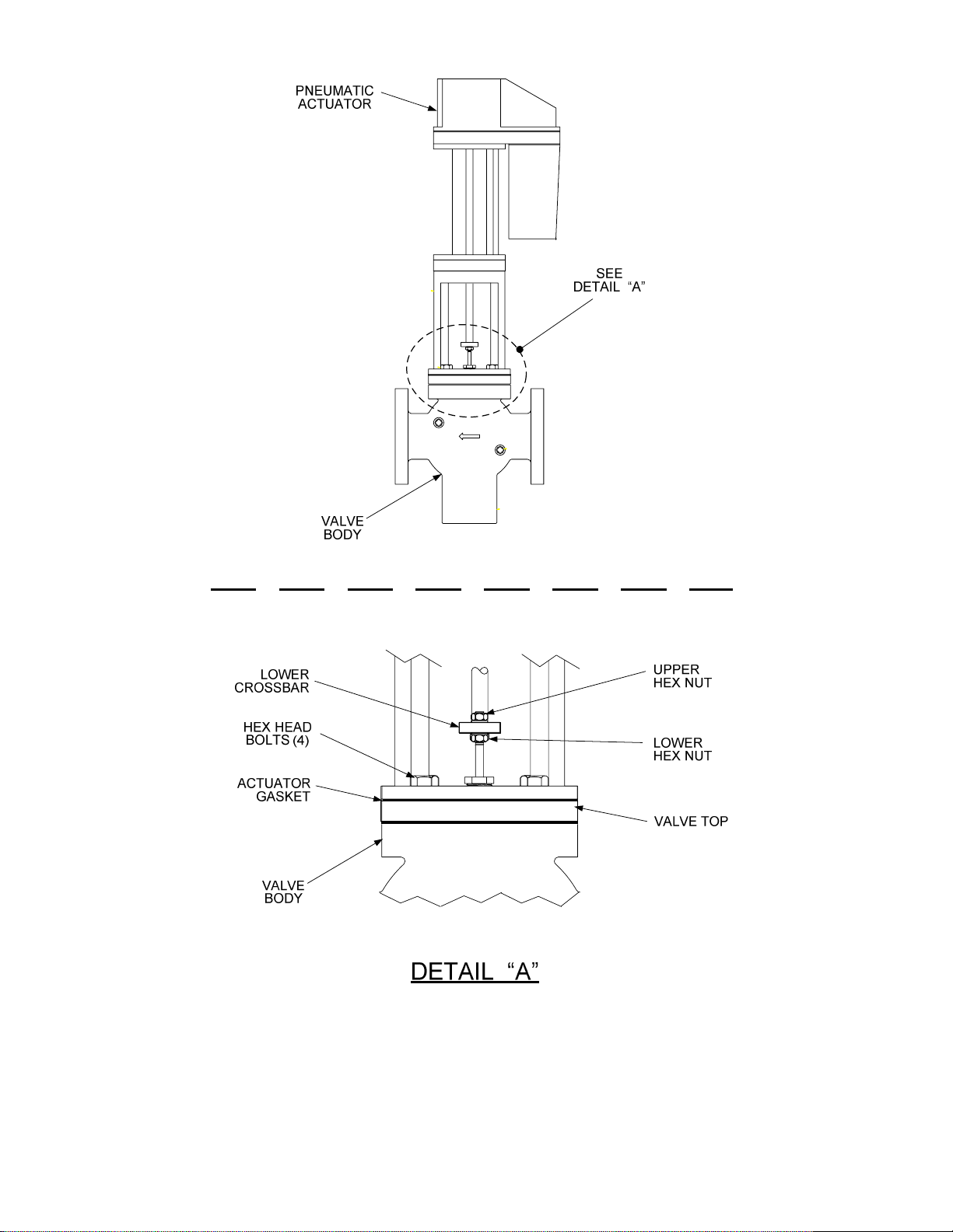
Figure 2-5. Electro-Hydraulic Control Valve Actuator Removal
15
Page 16

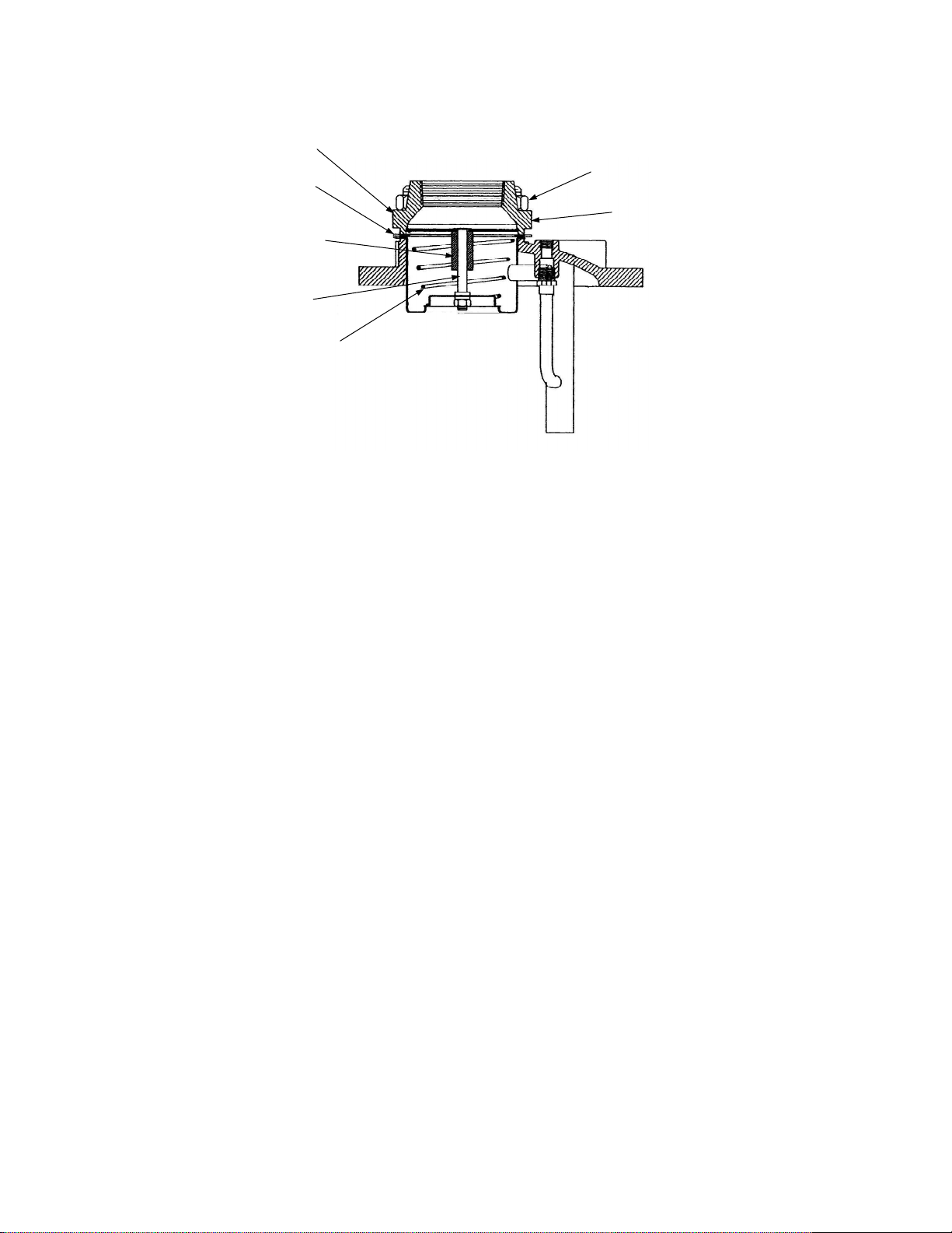
2.5.3 Self-Contained Control Valve Actuator Removal
Refer to Figure 2-6 and remove the Self-Contained Valve Actuator as follows:
1. Loosen the locknut on the thermal element adjustment sleeve. Unscrew the adjustment sleeve
to remove the sleeve and thermal element from the Actuator.
2. Carefully loosen the compression fittings on the upstream and downstream tubing to relieve
any trapped pressure buildup. Completely remove both the upstream and downstream tubing
assemblies and compression fittings. The tapped NPT ports in the Valve Body will be plugged
during the replacement procedures in Section 3.
3. Remove the hex head cap screws securing the Actuator to the Valve Body. Valve sizes from
1” to 2” have 6 cap screws, while sizes 2 ½” to 4” Valves have 8 cap screws.
CAUTION
Use care when performing step 4 to avoid damaging or scratching internal
Valve Body parts. It is imperative that the Actuator be lifted straight up to avoid
sticking or binding.
4. Lift the Actuator Housing straight up and off the Valve Body. Doing so will also remove the
entire inner valve assembly (Figure 2-7), including the Valve Stem, Seat, Valve Plug Shaft and
Top/Bottom Pistons. Depending on the age and condition of the valve, considerable force may
be required to pull the Pistons through the Valve Body. If it cannot be removed, the Valve
Stem may be used as an impact hammer to remove scale build-up on the internal valve
surfaces and allow Piston removal.
Replacement parts for these removed items are provided in the applicable Retrofit Kit for the
Valve size being retrofitted. These items will be replaced in Section 3. The Retrofit Kit also
contains a new Lower Shaft, Valve Top/Gasket, plus additional replacement items for the
Valve being retrofitted.
5. Proceed as follows, depending on the size of the Valve being retrofitted:
(a) For 2 ½ to 4 inch Valves, separate the Valve Seat Retaining Disc from the Valve Seat by
removing the four (4) cap screws (Figure 2-7).
(b) For 1 to 2 inch Valves, hold the Valve Plug Shaft with a pair of pliers and remove the
Valve Stem Retaining Nut from the Shaft (Figure 2-8).
6. Insert a 1/8 inch steel rod through the hole near the top of the Valve Stem (Figure 2-7 or 2-8).
NOTE
If “flats” are provided on the Actuator Connecting Shaft and Valve Stem, openend wrenches may be used in step 7 to disconnect the Valve Stem and
Actuator Shaft.
7. Grasp the Actuator Connecting Shaft (Figure 2-7 or 2-8) with a pair of pliers. Carefully turn the
Valve Stem counterclockwise and separate it from the Actuator Connecting Shaft.
16
Page 17
8. Replacement of all required Valve parts will be accomplished using the appropriate
instructions and illustrations in Section 3.
THERMAL ELEMENT
ADJUSTMENT SLEEVE
LOCKNUT
1/8" NPT
COMPRESSION
ELBOWS
DOWNSTREAM
TUBE
VALVE
BODY
UPSTREAM
TUBE
HEX HEAD
CAP SCREWS
1/4" NPT
COMPRESSION
ELBOW
Figure 2-6. Self-Contained Control Valve Actuator Removal
17
Page 18
Figure 2-7. Self-Contained Control Valve Actuator Removal – 2 ½” to 4”
Figure 2-8. Self-Contained Control Valve Actuator Removal – 1” to 2”
18
Page 19

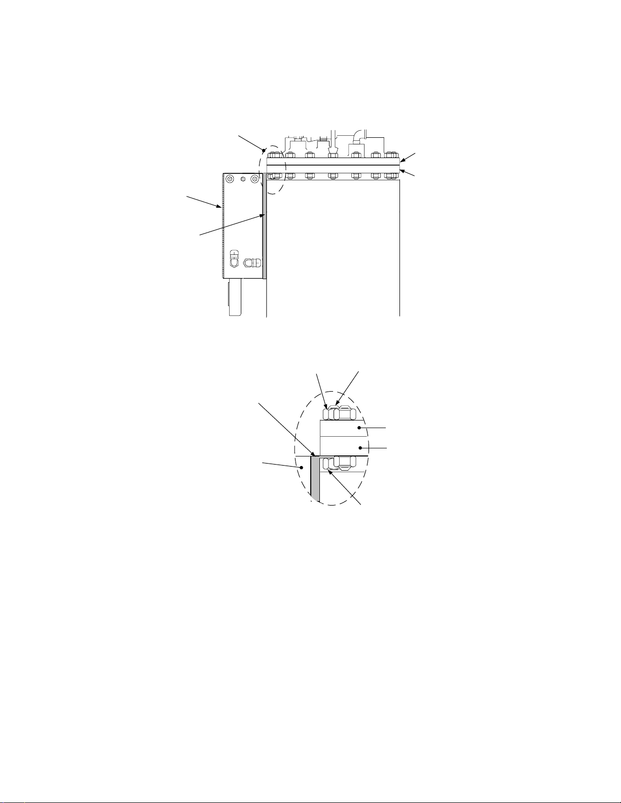
2.6 Control Box Removal
The existing Control Box (Figure 2-1) is secured to the Heat Exchanger using a special mounting
bracket. The top end of this mounting bracket contains a slotted cutout which is inserted around one
of the studs securing the top head to the shell flange. A hex nut secures the bracket in place. The
currently installed Control Box will no longer be used. However, the mounting bracket will be reused to
mount the new ECS Control Box. Remove the Control Box and mounting bracket assemblies as
follows:
1. Check to ensure that the external power source has been turned off.
2. Disconnect all power supply wiring to the Control Box. Also, disconnect all wiring between the
Control Box and any external Solenoid Valves.
3. If a Pneumatic Control Valve Actuator is currently installed on the Heater, disconnect the air
supply and control air tubing from the Control Box.
4. Disconnect the Pressure Gauge compression fittings.
5. Cut all wire ties leading to the Control Box. Do not cut the thermal element.
6. Loosen, but do not remove, the hex nut securing the Control Box Mounting Bracket to the Top
Head stud (Figure 2-9).
7. Completely remove the Control Box and Mounting Bracket from the Water Heater.
8. Open the Control Box door. From the rear of the Control Box, remove the six 8-32 screws
securing the Rear Mounting Panel to the enclosure (Figure 2-10).
9. Remove the Rear Mounting Panel from the Control Box to access the two screws securing the
Mounting Bracket to the Box
IMPORTANT
Save the Control Box Mounting Bracket when it is removed from the Control
Box. This Mounting Bracket will be used to install the new ECS Control Box.
10. Remove the two screws securing the Mounting Bracket to the Control Box. Separate the
Control Box and Mounting Bracket. This Control Box will no longer be used and can be
discarded. However, the Mounting Bracket will be reused to attach the new ECS Control Box
to the Heater in Section 4.
19
Page 20
SEE
DETAIL “A”
TOP HEAD
SHELL FLANGE
CONTROL
BOX
MOUNTING
BRACKET
HEX NUT
MOUNTING
BRACKET
(SAVE)
CONTROL
BOX
STUD
TOP HEAD
SHELL FLANGE
HEX NUT
DETAIL “A”
Figure 2-9. Control Box Mounting Details
20
Page 21
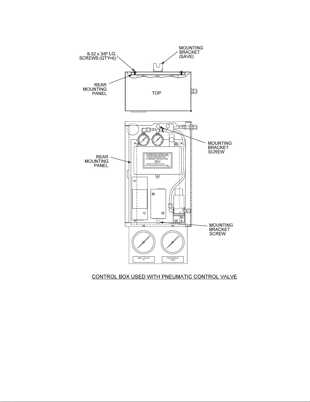
Figure 2-10. Control Box With Door Open
21
Page 22

3. RECOMMENDED REPLACEMENT OF VALVE ASSEMBLY PARTS
As mentioned in paragraph 2.5, AERCO recommends that the Valve Seat and Packing be replaced
on the Valve Body, prior to installing the ECS Retrofit Kit items described in Section 4. Valve Bodies
which previously utilized Self-Contained Actuators must
such as: a Valve Top, Valve Stem and a Packing Nut.
Refer to the applicable paragraphs which follow for the Valve size and Actuator type used on your
system.
be modified to include new additional items
NOTE
The procedures in paragraphs 3.1 and 3.2 which follow, assume that the
previously installed Pneumatic, Electro-Hydraulic or Self-Contained Actuator
has already been removed.
3.1 Valves Previously Equipped With Pneumatic or Electro-Hydraulic Actuators
The parts replacement items required for Valve Bodies which previously used Pneumatic or ElectroHydraulic Actuators are basically identical. Only minor variations exist for the various Valve Body
sizes. The Valve Body components for 1.00” to 2.00” and 2.50” to 4.00” are shown in Figures 3-1 and
3-2, respectively.
3.1.1 Valve Disassembly Procedure
Proceed as follows:
NOTE
Steps 1 through 5 which follow apply to all valve sizes shown in Figure 3-1
and 3-2.
1. Remove the Hex Nut (17) from the Valve Body Shaft.
2. Remove the Packing Nut (18) and Packing Assembly (20).
3. Remove the Bolts or Cap Screws (14) securing the Valve Top (21).
4. Remove the Valve Top (21) and Valve Top Gasket (13).
5. Carefully lift out the entire Shaft /Seat/Piston Assembly.
6. For 1 inch to 2 inch Valve sizes, refer to Figure 3-1 and remove the following items in the order
specified:
(a) Lock Washer (23)
(b) Retaining Ring (11)
(c) Pilot Spring (10)
22
Page 23

(d) Valve Stem Retaining Nut (35)
(e) Lower Shaft (16) and Valve Stem (12)
(f) Retaining Disc (8)
(g) Disc Seat (7)
(h) Seat Retainer (34)
(i) Valve Plug Shaft (5)
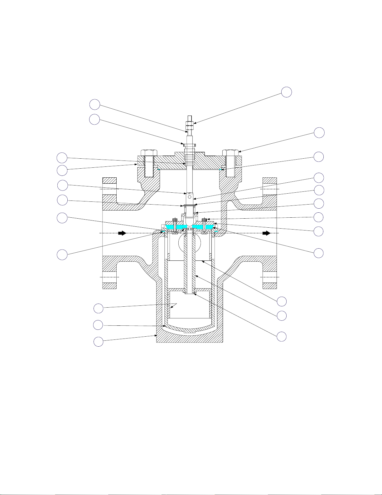
7. For 2 ½, 3 and 4 inch Valve sizes, refer to Figure 3-2 and remove the following items in the
order specified:
(a) Lock Washer (23)
(b) Pilot Spring Retainer (11)
(c) Pilot Spring Backup Washer (31), - 4 inch Valve Only
(d) Pilot Spring (10)
(e) Socket Head Cap Screws (9)
(f) Valve Seat Retaining Disc (8)
(g) Lower Shaft (16) and Valve Stem (12)
(h) Valve Seat (7)
(i) Top Piston (6) and Bottom Piston (3) Assemblies
8. Clean all parts thoroughly and remove all dirt and/or scale.
9. Next, proceed to the Valve Reassembly procedures in paragraph 3.1.2 and replace the items
indicated with the new parts provided in the Retrofit Kit.
23
Page 24
Figure 3-1. Valve Assembly Sizes 1.00” to 2.00”
24
Page 25

PARTS LIST TABLE FOR VALVE ASSEMBLY SIZES 1.00” TO 2.00”
VALVE SIZE AND PART NUMBERS
ITEM QTY PART NAME 1.00 INCH 1.25 INCH 1.50 INCH 2.00 INCH
1 1 VALVE BODY 20762 20759 20758 20761
2 1 SEAT CAGE 16844 16845 16837 16843
3 1 BOTTOM PISTON 121540 121525 121502 121529
4 NOT USED
5 1 VALVE PLUG SHAFT 16849 16839 16838 16848
6 1 TOP PISTON 121539 12154 121501 121530
7 1 DISC SEAT 121541 121527 121510 121531
8 1 RETAINING DISC 121542 121513 121504 121532
9 NOT USED
10 PILOT SPRING 121528 121528 121528 121528
11 1 RETAINING RING 121545 121545 121545 121545
12 1 VALVE STEM 122655 122654 122651 122650
13 1 VALVE TOP GASKET 122136 122136 122136 122136
14 6 BOLT, HEX, 3/8-16 122405 122405 122405 122405
16 1 LOWER SHAFT 121979 121980 121980 121982
17 2 HEX NUT, 1/4-20 6-226 6-226 6-226 6-226
18 1 PACKING NUT 122664 122664 122664 122664
19 2 BOLT, HEX 3/8-16 x 5/8 LG 54014 54014 54014 54014
20 1 PACKING ASSY 121567 121567 121567 121567
21 1 VALVE TOP 16943 16943 16943 16943
22 NOT USED
23 1 LOCKWASHER 122666 122666 122666 122666
24 1 SEAT CAGE GASKET 123080 123081 123082 123083
ITEMS
25
THRU
30
31 1
32 1 TOP PISTON RETAINING NUT 121543 121543 121543 121543
33 1 LOWER PILOT SEAT ASSY 121505 121505 121505 121505
NOT SHOWN
BOTTOM PISTON RETAINING NUT
122982 122982 122982 122982
34 1 SEAT RETAINER N/A 121559 121506 121506
35 1 VALVE STEM RETAINING NUT 121503 121503 121503 121503
25
Page 26
17
16
18
14
20
21
23
31
22
24
6
3
5
2
4
1
13
12
11
10
9
8
7
Figure 3-2. Valve Assembly Sizes 2.50” to 4.00”
26
Page 27

PARTS LIST TABLE FOR VALVE ASSEMBLY SIZES 2.50” TO 4.00”
VALVE SIZE AND PART NUMBERS
ITEM QTY PART NAME 2.50 INCH 3.00 INCH 4.00 INCH
1 1 VALVE BODY 20765-1 20766-1 20775
2 1 SEAT CAGE 16961 161004 161046
3 1 BOTTOM PISTON 16962 161007 161048
4 1 PISTON RETAINING RING 122173 122173 122234
5 1 VALVE PLUG SHAFT 16972 161006 161047
6 1 TOP PISTON 16970 161005 161050
7 1 VALVE SEAT 121935 122032 122178
8 1 VALVE SEAT RETAINING DISC 121934 122031 122177
9 4 10-32 x 3/4” LG. SOCKET HD. CAP 122174 122174 122238
10 1 PILOT SPRING 122081 122232 121823
11 1 PILOT SPRING RETAINER 122082 122082 122173
12 1 VALVE STEM 122648 122658 122659
13 1 VALVE TOP GASKET 122083 122204 122203
14 4 CAP SCREW 5/8-11 x 1-1/2” LG. N/A 6-310 6-310
15 2 3/8-16 NUT (4” VALVE ONLY) N/A N/A 6-264
16 1 LOWER SHAFT 122223 122230 122224
17 2 1/4-20 NUT 6-226 6-226 N/A
18 1 PACKING NUT 122664 122665 122665
19 2 3/8-16 x 5/8” LG. CAP SREWS 54014 54014 54014
20 1 PACKING ASSY 121567 121568 121568
21 1 VALVE TOP 18781 18823 18824
22 1 SEAT BACK-UP RING 122326 122327 122328
23 1 LOCKWASHER 122666 122667 122667
24 1 SEAT CAGE GASKET 123084 123085 123086
ITEMS
25
THRU
30
31 1 PILOT SPRING BACKUP WASHER N/A N/A 122246
NOT SHOWN
27
Page 28

3.1.2 Valve Reassembly Procedure
Reassembly is accomplished by basically reversing the previous Disassembly steps. Refer to Figure
3-1 or 3-2 for the applicable Valve size. Perform the following steps in the order specified and
REPLACE the items shown in BOLD type with the new parts provided in the Retrofit Kit.
1. For 1 inch to 2 inch Valve sizes, refer to Figure 3-1 and reassemble or replace the following
items in the order specified:
(a) Valve Plug Shaft (5)
(b) Seat Retainer (34)
(c) Replace Disc Seat (7)
(d) Retaining Disc (8)
(e) Lower Shaft (16) and Valve Stem (12)
(f) Valve Stem Retaining Nut (35)
(g) Pilot Spring (10)
(h) Retaining Ring (3)
(i) Lock Washer (23)
(j) Proceed to step 3 and continue the Valve Reassembly process. Steps 3 through 6 apply
to ALL valve sizes.
2. For 2 ½, 3 and 4 inch Valve sizes, refer to Figure 3-2 and reassemble or replace the following
items in the order specified:
(a) Top Piston (6) and Bottom Piston (3) Assemblies
(b) Replace Valve Seat (7)
(c) Lower Shaft (16) and Valve Stem (12)
(d) Valve Seat Retaining Disc (8)
(e) Socket Head Cap Screws (9)
(f) Pilot Spring (10)
(g) Pilot Spring Backup Washer (31), - 4 inch Valve Only
(h) Pilot Spring Retainer (11)
(i) Lock Washer (23)
(j) Proceed to step 3 and continue the Valve Reassembly process. Steps 3 through 6 apply
to ALL valve sizes.
3. Replace Valve Top Gasket (13) and reassemble Valve Top (21) on Valve Body (1).
4. Secure Valve Top (21) to Valve Body (1) with the Bolts or Cap Screws (14).
28
Page 29

5. Replace Packing Assembly (20) and reassemble Packing Nut (18) in Valve Top (21).
6. The last step of the Valve Reassembly procedure is to replace two Hex Nuts on the Valve
Shaft. Valve sizes from 1 to 3 inches contain two 1/4-20 Hex Nuts in the Retrofit Kit. However,
4 inch Valves contain two 3/8-16 Hex Nuts in the Kit. Replace the appropriate Hex nuts on the
Valve Shaft.
3.2 Valves Previously Equipped With Self-Contained Actuators
The internal parts and assemblies contained in Valves which were previously equipped with SelfContained Actuators must basically be rebuilt with the items provided in the Retrofit Kit. The Retrofit
Kit for Valve sizes from 1.00” to 2.00” include an Inner Pilot Assembly Kit (29021-[ ]) and a Valve
Piston Assembly Kit (12168-[ ]). The items in these kits are shown in Figures 3-3 and 3-4. Kits for
Valve sizes from 2.50” to 4.00” include a Main Valve Assembly Kit (27006-[ ]) containing the items
shown in the exploded view in Figure 3-5.
In addition to replacement the parts contained in these Kits, new items must be added to ALL Valve
Bodies which previously used Self-Contained Actuators. These items include:
• Lower Shaft
• Valve Top
• Valve Top Gasket
• Hex Bolts (1” to 2” Valves) or Cap Screws (2.5” to 4.0” Valves) to secure Valve Top
• Packing Assembly
• Packing Nut
• 1/4” NPT Plugs which get inserted into tapped holes in Valve Body
Refer to Figure 3-1 (1” to 2” Valves) or Figure 3-2 (2.5” to 4” Valves) for the locations of these items.
29
Page 30

5
4
3
2
1
1.00"-2.00" CXT-P (PNEUMATIC)
ITEM
REQ
1
2
3
4
5
VALVE STEM
1
1
VALVE STEM RETAINING NUT
LOWER PILOT PRE-LOAD SPRING
1
1
PRE-LOAD SPRING RETAINING RING
1 LOCKWASHER
DESCRIPTION
1.00"
122655
121503
121528
121545
122666 122666 122666 122666
1.25"
122654
121503
121528
121545
1.50" 2.00"
122651
121503
121528
121545
122650
121503
121528
121545
Figure 3-3. Inner Pilot Assembly Kit (29021-[ ]) for 1.00” to 2.00” Valves
30
Page 31

Figure 3-4. Valve Piston Assembly Kit (121618-[ ]) for 1.00” to 2.00” Valves
31
Page 32

Figure 3-5. Main Valve Assembly Kit (27006-[ ]) for 2.50” to 4.00” Valves
32
Page 33

4. INSTALLATION OF RETROFIT KIT ITEMS
When installing the new Electronic Control Valve Actuator and Electronic Control System (ECS)
Control Box, a number of ancillary items must also be installed or replaced. These include a new
Flow Meter, a replacement Water Solenoid Valve and several Temperature Sensors.
To install the Retrofit Kit items, proceed as follows:
4.1 Installation of Control Valve Actuator and Linkage Assembly
Identical Actuator Assemblies, part no. 69009 are used on all AERCO Control Valve sizes from 1 inch
to 4 inches. However, there are two types of Linkage Assemblies designated part no. 24038-1 and -2
used with different sizes of AERCO Control Valves. Linkage Assembly, part no. 24038-1 is used on
AERCO Valve sizes ranging from 1 inch to 3 inches. The 24038-2 Linkage Assembly is used only on
4 inch Valves. The primary difference between these two assemblies is the Linkage Assembly
Adapter shown in Figure 4-1. In addition, the linkage pin location for 24038-1 assemblies will vary for
1 to 2 inch Valves and for 2 ½ to 3 inch Valves as shown in the upper portion of Figure 4-1.
Figure 4-1. Linkage Assemblies Part No. 24038-1 & 24038-2
33
Page 34

The installation procedures for the Linkage Assembly and Actuator Assembly are provided in
paragraphs 4.1.1 and 4.1.2 which follow.
4.1.1 Linkage Assembly Installation
Remove the Linkage Assembly from the Retrofit Kit and install as follows:
1. Check to ensure that the correct Linkage Assembly and Adapter are provided for the valve
size being retrofitted (Figure 4-1). Also, ensure that the Linkage pin is inserted in the correct
location for this valve size.
CAUTION
It is imperative that the Gasket provided with the Linkage Assembly be
installed between the Valve Top and Linkage Assembly. Failure to do so
will void the equipment warranty.
2. Refer to Figure 4-2 and position the Gasket and Linkage Assembly on the Valve Top as
shown.
3. Secure the Linkage Assembly to the Valve Top using the two 3/8-16 Hex Head Bolts provided.
4. Install two 1/4-20 Hex Nuts (1 to 3 inch Valves), or two 3/8-16 Hex Nuts (4 inch Valve) on the
Valve Shaft (Figure 4-2).
5. Rotate the two Hex Nuts clockwise towards the lower end of the Valve Shaft.
6. Install the Indicator Plate on the Valve Shaft with the curved end facing upward as shown in
Figure 4-3.
7. Attach the Valve Shaft to the Linkage Adapter by rotating the Shaft counterclockwise (as
viewed from above). If the Valve Shaft cannot be turned by hand, use an open-end wrench to
turn the “double-nuts” on the Shaft until it engages the Linkage Adapter threads.
8. Press down on the Valve Shaft to compress the Pilot Spring in the Valve Body.
9. Raise the Indicator Plate so it is contacting the bottom of the Adapter and observe the position
on the Linkage Scale. Rotate the Valve Shaft as necessary until the raised Indicator Plate is
aligned with the “0” (zero) marking on the Linkage Scale.
10. When properly aligned, raise the Hex Nuts on the Valve Shaft by rotating them
counterclockwise. Position the Hex Nuts so they are snug against the Indicator Plate.
11. Proceed to paragraph 4.1.2 to install the Actuator Assembly.
34
Page 35

U-BOLT &
HEX NUTS
ACTUATOR
HORIZONTAL
SHAFT
8 mm HEX NUTS (2)
LINKAGE
ADAPTER
HEX HEAD
BOLTS (2)
(ON BOTTOM SIDE
OF BRACKET)
INDICATOR
PLATE
GASKET
VALVE SHAFT
HEX NUTS (2)
VALVE TOP
Figure 4-2. Actuator and Linkage Installation Details
35
Page 36

ITEM QTY PART DESCRIPTION PART NUMBER
1 1 LINKAGE ASSEMBLY 24038-1 (1” TO 3” VALVES)
2 1 SCALE
3 2 8-32 HEX NUT 123322
4 2 3/8-16 X 5/8 LONG CAP SCREW 54014
5 1 GASKET 81046
59028-1 (1” VALVE)
59028-1.25 (1.25” VALVE)
59028-1.5 (1.5” VALVE)
59028-2 (2” VALVE)
59028-2.5 (2.5” VALVE)
59028-3 ( 3” VALVE)
59028-4 (4” VALVE)
Figure 4-3. Linkage Installation Details
4.1.2 Actuator Installation
Remove the Actuator Assembly (69009) from the Retrofit Kit and install as follows:
1. Depress and hold the Clutch Button (Figure 4-4) and rotate the pointer to approximately 80° on
the dial. Release the Clutch Button when properly positioned.
CAUTION
DO NOT DEPRESS THE CLUTCH BUTTON WITH POWER APPLIED TO
THE ACTUATOR
2. Slide the Actuator onto the Linkage Assembly Shaft (Figures 4-2 & 4-4). Ensure that the pin on
the Linkage Assembly is inserted in the center slot on the bottom of the Actuator (Figure 4-4).
36
Page 37

3. Press down on the Linkage Adapter and verify that the Indicator Plate is aligned with the “0”
Scale marking.
4. With the Indicator Plate properly aligned, tighten the U-bolt hex nuts using an 8 mm wrench.
Torque the nuts to 60 in-lbs.
5. This completes the mechanical installation of the Actuator Assembly. The electrical
connections will be made during installation of the Control Box in paragraph 4.7.
9
0
Figure 4-4. Actuator Assembly, Part No. 69009
37
Page 38

4.2 Installation of ECS Components on Top Head Assembly
The ECS to be installed on the Top Head Assembly include:
• Outlet Flange & Gasket
• Outlet Temperature Dual Sensor
• Water Solenoid Valve and piping
• Plugs for previously installed: Shunt Tube, Thermal Element, Feedback Sensor, etc., etc.
4.2.1 Outlet Flange
New Outlet Flange (95015) and Gasket (122152) are provided in the Retrofit Kit. This new Flange
contains a tapped hole which permits easy installation of the new Outlet Temperature Dual Sensor
described in para. 4.2.2. To install the new Outlet Flange and Gasket:
1. Ensure that the Outlet opening in the Top Head (see Figure 2-1, sht. 3) has been thoroughly
cleaned of any gasket residue from the previously installed gasket.
2. Position the new Outlet Flange and Gasket on the four studs protruding from the Top Head on
the Heater.
3. Secure the Outlet Flange to the Top Head using the four hex nuts previously removed in para.
2.3, step 8. Tighten the hex nuts using an alternating pattern to obtain a uniform seal.
Reconnect the outlet piping to new Outlet Flange.
4.2.2 Outlet Temperature Dual Sensor
The Outlet Temperature Dual Sensor (61008-1) provided in the Retrofit Kit includes two Type J
Thermocouples which are housed in a thermowell. The Thermocouple leads are terminated with a 4pin connector.
1. Install the Outlet Temperature Dual Sensor in the tapped hole provided on the new Outlet
Flange installed in the previous paragraph.
2. Connection of the Dual Sensor electrical connector will be accomplished following installation
of the ECS Control Box (para. 4.4).
4.2.3 Water Solenoid
The 120 VAC Water Solenoid removed in Section 2 will be replaced with the 24 VDC Solenoid Valve
provided in the Retrofit Kit. Proceed as follows:
1. Attach the new Solenoid Valve (49029) to the nipple in the Top Head (ref. Figure 2-1, sht. 3)
2. Reconnect the previously installed drain piping to the Solenoid Valve outlet.
3. Electrical connection of the Solenoid Valve will be accomplished following installation of the
ECS Control Box.
38
Page 39

4.2.4 NPT Plugs
Each Retrofit Kit contains four NPT Plugs in the following sizes:
• 1/4 inch
• 1/2 inch
• 3/4 inch
• 1 inch
These plugs are installed in the remaining tapped holes in the Top Head where components used with
the previous Control System were installed. The location and size of the required Plugs may vary
depending on the specific AERCO Heater Model being retrofitted. Refer to Figure 2-1 for reference.
Ensure that all tapped holes in the Top Head have been plugged before proceeding with the
installation.
4.3 Flow Meter Installation
As part of the Electronic Control System (ECS) Retrofit, a new Flow Meter must be added to the
Packaged Heater. The purpose of this meter is to provide a feed-forward signal to the Temperature
Controller contained in the ECS Control Box. The installation location will vary depending on whether
the AERCO Water Heater Model being retrofitted is a Helitherm Heat Exchanger (A-Plus, B-Plus, BPlus II and E-Plus), or a Double-Wall Heat Exchanger (DW-24, DW-45, DW-68). For Helitherm Model
Heaters, the Flow Meter is installed between the Cold Water Inlet and the Drain Outlet on the Bottom
Head of the Heater (Figures 4-5 and 4-6). However, for Double Wall Heater Models, the Flow Meter is
installed between the Cold Water Inlet and Drain Outlet on the Heater Shell. See Figure 4-7. All
required installation components are included in the Retrofit Kit. Proceed to paragraph 4.3.1
(Helitherm) or 4.3.2 (Double-Wall), as applicable.
IMPORTANT
Prior to installing the inlet or outlet tubes to the Flow Meter (step 2 of
paragraphs 4.3.1 and 4.3.2), it will be necessary to first temporarily remove
the strain relief assembly shown in Figure 4-8. After removal, perform the
following steps:
1. First, hand-tighten the inlet and outlet tube compression fittings to the Flow
Meter. Position the “flats” on the fitting to avoid interfering with
reinstallation of the strain relief in the next step.
2. Next, attach the strain relief to the Flow Meter cable (Figure 4-8).
3. After the strain relief is installed, fully tighten the inlet and outlet tube
compression fittings to the Flowmeter.
39
Page 40

Figure 4-5. Typical (B+) Helitherm Heater Flow Meter Location – Front View
COLD WATER
INLET
COMPRESSION FITTING
(1/4" NPT x 1/2" TUBE)
TO ECS
CONTROL
BOX
INLET TUBE
COMPRESSION FITTINGS
(1/2" NPT x 1/2" TUBE)
FLOW METER
COMPRESSION FITTINGS
(1/2" NPT x 1/2" TUBE)
FLEXIBLE OUTLET TUBE
COMPRESSION FITTING
(1/4" NPT x 1/2" TUBE)
DRAIN WITH
MODIFIED
NIPPLE
FRONT
REAR
Figure 4-6. Typical (B+) Helitherm Heater Flow Meter Location – Bottom View
40
Page 41

Figure 4-7. Double-Wall Heater Flow Meter Location
4.3.1 Flow Meter Installation For Helitherm Heaters
For A-Plus, B-Plus, B-Plus II and E-Plus Heaters, the Flow Meter connections are made at the Bottom
Head of the Heater. The Flow Meter Inlet side connects to the Cold Water Inlet using Rigid Tubing.
However, the Outlet side of the Flow Meter connects to the Drain Outlet using Flexible Tubing. A
typical B-Plus or B-Plus II installation is shown in Figures 4-5 and 4-6. Refer to these Figures when
performing the following steps:
1. Obtain the Flow Meter, Rigid Inlet Tube, Flexible Outlet Tube and Compression Fittings from
the Retrofit Kit. Refer to Appendix A for the applicable part numbers for the tubing and fittings
required for the unit being retrofitted.
2. Attach the Rigid Inlet Tube and Flexible Outlet Tube to the Flow Meter using the fittings
provided in the kit.
3. Next, obtain the Modified 2” NPT Nipple (9006) from the Retrofit Kit.
4. Remove the existing 2’ NPT Nipple from the Drain Outlet on the Bottom Head.
5. Install the new Modified 2” NPT Nipple in the Bottom Head. Attach the ¼ NPT coupling to the
tapped hole in the Modified Nipple.
41
Page 42

6. Connect the Flow Meter Outlet Flexible Hose to the Modified Nipple on the Drain Outlet using
the compression fitting. Connect the Rigid Flow Meter Inlet Tube to the Cold Water Inlet using
the compression fitting provided in the kit.
7. Position the Flow Meter so that the Paddle Wheel is in the “Vertical” plane as shown in Figure
4-8. Tighten all Flow Meter connection fittings.
Figure 4-8. Flow Meter Orientation
4.3.2 Flow Meter Installation For Double-Wall Heaters
Flow Meter connections for Double-Wall Heater Models DW-24, DW-45 and DW-68 are made on the
Shell as shown in Figure 4-7. As with Helitherm Models, Rigid Tubing is used for the Flow Meter Inlet
connection to the Cold Water Inlet and Flexible Tubing is used for the Outlet connection at the Drain.
Flow Meter installation is accomplished as follows:
1. Obtain the Flow Meter, Rigid Inlet Tube, Flexible Outlet Tube and Compression Fittings from
the Retrofit Kit.
2. Attach the Rigid Inlet Tube and Flexible Outlet Tube to the Flow Meter using the fittings
provided in the kit.
3. Next, obtain the 3/4” Close Nipple (9-234) and 3/4 x 1/4 x 3/4” Tee (59032) from the Retrofit
Kit.
4. If installed, remove the 3/4” NPT Plug from the Drain Port on the Heater Shell (Ref. Figure 2-2,
sht 1).
5. Install the Close Nipple and Tee in the Drain Port (Figure 4-7)
6. Connect the Flow Meter Outlet Flexible Tubing to the Drain Outlet Tee as shown in Figure 4-7.
Connect the Rigid Inlet Tube from the Flow Meter to the Cold Water Inlet using the
compression fitting provided.
7. Position the Flow Meter so that the Paddle Wheel is in the “Vertical” plane as shown in Figure
4-8.
42
Page 43

NOTE
Paragraph 4.4 applies ONLY to Water-to-Water Heater Models which include
E-Plus and Water-to-Water Double-Wall Models. Disregard the procedures in
paragraph 4.4 for ALL Steam-to-Water Heater Models and proceed directly to
paragraph 4.5.
4.4 Boiler Water Inlet and Outlet Temperature Sensors – (Water-to-Water Heaters)
If the Water Heater being retrofitted is an E-Plus or a Water-to-Water Double-Wall, two additional
Temperature Sensors (Type J Thermocouples) must be added. These are the Boiler Water Inlet
Temperature Sensor and Boiler Water Outlet Temperature Sensor. For E-Plus (Helitherm) Heaters,
the Inlet and Outlet Sensors are mounted in the Bottom Head and Top Head, respectively as shown in
Figure 4-9. For Water-to-Water Double-Wall Heaters, the Boiler Water Inlet and Outlet Temperature
Sensors are mounted at the locations shown in Figure 4-10.
These two additional Temperature Sensors are identical (part no. 61009-1) and therefore can be
installed in either location.
4.4.1 E-Plus Water Heaters
Refer to Figure 4-9 and install the Boiler Water Inlet and Outlet Sensors as follows:
1. Check to ensure that the capillary tubes and compression fittings have been removed from the
Boiler Inlet and Outlet Valve Spool Piece Assemblies shown in Figure 4-9. If they have not
been previously remove, disconnect and remove these items at this time.
2. Install the Boiler Water Inlet Temperature Sensor in the tapped opening in the Valve Spool
Piece Assembly which connects to the Boiler Water Inlet on the Bottom Head Heater.
3. Install the Boiler Water Outlet Temperature Sensor in the tapped opening in the Valve Spool
Piece Assembly which connects to the Boiler Water Outlet on the Top Head of the Heater.
4. The electrical connector plugs on the Inlet and Outlet Boiler Water Temperature Sensors will
be connected after the ECS Control Box is installed (paragraph 4.5).
43
Page 44

R
BOILER WATE
OUTLET SENSOR
LOCATION
BOILER WATER
VALVE SPOOL
PIECE ASSEMBLY
BOILER WATER
INLET SENSOR
LOCATION
OUTLET
CXT-E
CONTROL
VALVE
BOILER WATER
INLET
VALVE SPOOL
PIECE ASSEMBLY
Figure 4-9. E-Plus Boiler Water Inlet and Outlet Temperature Sensor Locations
4.4.2 Double-Wall Water Heaters
The sensor installation locations for a Water-to-Water Model DW-24 differ slightly from the locations
used for DW-45 and DW-68 Models as shown in Figure 4-10. DW-45 and DW-68 Sensors are
mounted on the Boiler Water Inlet and Outlet Flanges. However, since these flanges do not exist for
the DW-24, the Sensors are mounted on the bottom of the Boiler Water Inlet and Outlet as shown in
Figure 4-10. Install the Boiler Water Inlet and Outlet Sensors as follows for the Model being retrofitted:
1. Check to ensure that the capillary tubes and compression fittings have been removed from the
Boiler Inlet and Outlet Flanges shown in Figure 4-10. If they have not been previously remove,
disconnect and remove these items at this time.
2. For DW-45 and DW-68 Models, install the Boiler Water Inlet Temperature Sensor in the
tapped opening in the Boiler Water Inlet Flange shown in Figure 4-10. For a DW-24 Model,
install the Sensor in the tapped hole at the bottom of the Boiler Water Inlet as shown.
3. For DW-45 and DW-68 Models, install the Boiler Water Outlet Temperature Sensor in the
tapped opening in the Boiler Water Outlet Flange shown in Figure 4-10. . For a DW-24 Model,
install the Sensor in the tapped hole at the bottom of the Boiler Water Inlet as shown.
4. The electrical connector plugs on the Inlet and Outlet Boiler Water Temperature Sensors will
be connected after the ECS Control Box is installed (paragraph 4.5).
44
Page 45

LEAK DETECTION PORT
DO NOT
PLUG OR OBSTRUCT !
THIS IS A VENTED U - TUBE HEAT
BOILER
WATER
OUT
EXCHANGER CONSTRUCTED WITH
DOUBLE WALL TUBE.
AN INNER OR OUTER TUBE
FAILURE IS INDICATED BY
BOILER
WATER
IN
BOILER WATER
OUTLET SENSOR
BOILER
WATER
OUT
BOILER WATER
OUTLET SENSOR
DW-24
LEAK DETECTION PORT
DO NOT
PLUG OR OBSTRUCT !
THIS IS A VENTED U -TUBE HEAT
EXCHANGER CO NST RUCTE D WIT H
DOUBLE WALL TUBE.
AN INNER OR OUTER TUBE
FAILURE IS IN DICA TED BY
FLOW FROM THIS PORT.
BOILER WATER
INPUT SENSOR
BOILER
WATER
BOILER WATER
INPUT SENSOR
IN
DW-45, DW-68
Figure 4-10. Boiler Water Inlet and Outlet Temperature Sensor Locations for
Water–to–Water Double-Wall Heaters
45
Page 46
NOTE
Paragraph 4.5 applies ONLY to Steam-to-Water Heater Models which include
A-Plus, B-Plus, B-Plus II Helitherm Models and Steam-to-Water Double-Wall
Models. Disregard the procedures in paragraph 4.5 for ALL Water-to-Water
Heater Models and proceed directly to paragraph 4.6.
4.5 Compound Pressure Gauge
If the Water Heater being retrofitted is Steam-to-Water Model, a Compound Pressure Gauge is
included in the Retrofit Kit. The Compound Pressure Gauge range will be sized to match the
requirements of the Heater being retrofitted. In addition to the Gauge, all required fittings necessary
for installation will be included in the kit.
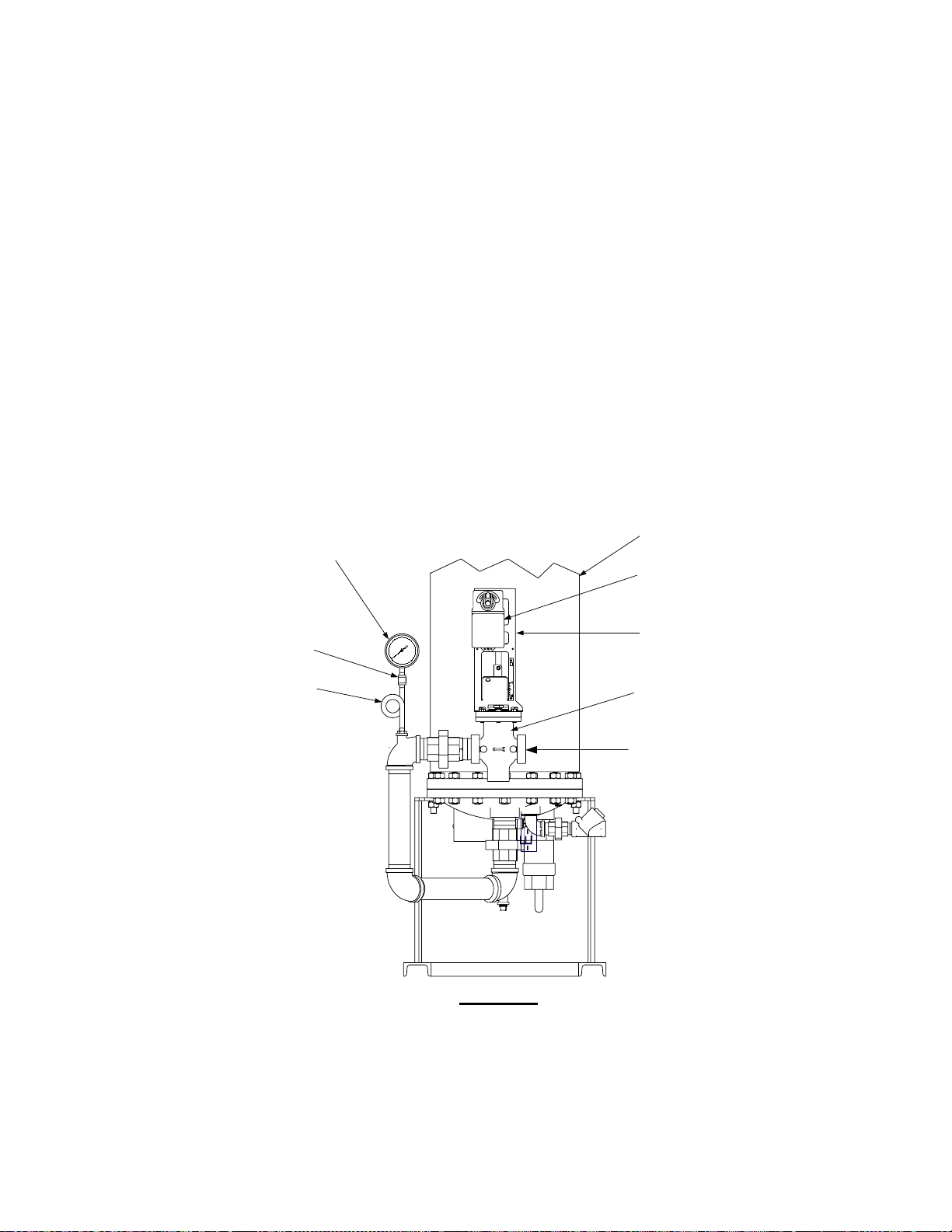
For Steam-to-Water Helitherm Models, the Compound Pressure Gauge will be mounted downstream
of the CXT-E Control Valve as shown in Figure 4-11. For Steam-to-Water Double-Wall Models, the
Gauge will be mounted on the steam inlet flange as shown in Figure 4-12.
COMPOUND PRESSURE GAUGE
(SHOWN ROTATED FOR CLARITY)
1/4" COUPLING
PIG TAIL
SHELL
CXT-E
ACTUATOR
LINKAGE
ASSY
CONTROL
VALVE
STEAM IN
SIDE VIEW
Figure 4-11. Compound Pressure Gauge Installation – Helitherm S/W Unit
46
Page 47

Figure 4-12. Compound Pressure Gauge Installation – Double-Wall S/W Unit
47
Page 48

4.5.1 Helitherm Steam-to-Water Units
For Helitherm Steam-to-Water units, refer to Figure 4-11 which shows a typical B-Plus Heater.
Proceed as follows:
1. Remove the Compound Pressure Gauge (8356-[ ]), Pig Tail (8-20) and 1/4” Coupling (9-3)
from the Retrofit Kit.
2. Install the Pig Tail in the tapped hole downstream of the CXT-E Control Valve.
3. Attach the 1/4” NPT Coupling and Pressure Gauge to the Pig Tail as shown in Figure 4-11.
Tighten all connections.
4.5.2 Double Wall Steam-to-Water Units
For Double-Wall Steam-to-Water units, refer to Figure 4-12. This Figure shows typical Compound
Pressure Gauge installation locations for DW-24 and DW-68 units.
1. Remove the Compound Pressure Gauge (8356-[ ]), Pig Tail (8-20), 1/4” NPT x 4” long Nipple
(91024) and two 1/4” NPT Couplings (9-3) from the Retrofit Kit.
2. For a DW-24 unit, install the 4” long NPT Nipple to the existing elbow on the Steam Inlet. For
DW-68 or DW-45 units, install the 4” long NPT Nipple to the Steam Inlet Flange.
3. Next install one of the 1/4” Couplings to the end of the 4” long Nipple.
4. Attach the Pig Tail, 1/4” Coupling and Compound Pressure Gauge as shown in Figure 4-12.
Tighten all connections
48
Page 49

4.6 Installation of New Orifice Disc
The Retrofit Kit contains a new Orifice Disc (part no. 49032-[ ]) sized for the applicable follow range
used by the Heater being retrofitted. The Orifice Disc is located in the Cold Water Inlet on the Water
Heater. For Helitherm Heater Models, the Cold Water Inlet is on the Bottom Head of the Heater as
shown in Figure 4-13. However, for Double-Wall Models, the Cold Water Inlet is located on the Shell
of the Heater as shown in Figure 4-14.
Refer to the applicable Figure for the unit being modified and install the new Orifice Disc and Spring
Ring as follows:
1. Obtain the Orifice Disc and Spring Ring from the Retrofit Kit.
2. Insert the Orifice Disc fully into the Cold Water Inlet until it contacts the stops. Ensure that the
Orifice is seated evenly in the Inlet.
3. Using a pair of needle-nose pliers, compress the ends of the Spring Ring and insert it fully into
place.
4. This completes the installation of the new Orifice Disc.
Figure 4-13. Cold Water Inlet Orifice Location – Typical Helitherm Heater
49
Page 50

FLOW
METER
SHELL
COLD WATER INLET
(SEE VIEW “A - A”)
A
INSULATION
A
DW-45, DW-68
ORIFICE
DISC
SPRING
RING
INLET
PIPE
VIEW “A - A”
Figure 4-14. Cold Water Inlet Orifice Location – Double-Wall Heater
50
Page 51

4.7 ECS Control Box Installation
The ECS Control Box is attached to the Water Heater using the old Control Box Mounting Bracket
removed in Section 2. Install the new ECS Control Box in accordance with the following steps:
1. Attach the ECS Control Box to the Mounting Bracket using the two 1/4-20 x 1/2 “ screws and
washers provided in the Retrofit Kit.
2. Insert the top end of the Mounting Bracket under the previously loosened hex nut at the top of
the Heater Shell (Figure 4-15). After the Bracket is vertically aligned, tighten the hex nut to
secure the Mounting Bracket and ECS Control Box to the Water Heater.
HEX NUTS
& STUD
MOUNTING
BRACKET
ECS CONTROL
BOX
SHELL
TEMP CONTROLLER
B+II
OVER TEMP SWITCH
SOLENOID
VALVE
TOP HEAD
SHELL FLANGE
MOUNTING
BRACKET
SCREWS
Figure 4-15. ECS Control Box Mounting Location
NOTE
External power at 120 to 240 VAC, 50/60 Hz is required to operate the
circuitry contained in the ECS Control Box. Power connections are made
internally by routing the power wiring through the cutout provided on the right
side of the Control Box.
3. Next, loosen the captive Phillips head screw on the right front portion of the Control Box
(Figure 4-16) to open the hinged door.
4. Swing open the door and loosen the captive Phillips head screw at the top of the recessed
panel (Figure 4-17). Swing down the panel to access terminal block TB-2 (Figure 4-18)
5. Feed the external 120 to 240 VAC, 60 Hz) power leads through the cutout in the right side of
the ECS Control Box.
51
Page 52

6. Connect the Line, Neutral and Ground leads to the TB-2 terminals shown in Figure 4-18.
7. Close the swing-down panel after the power leads are secured to TB-2. Tighten the captive
screw to secure the recessed panel.
8. Close the front door of the ECS Control Box and tighten the captive screw to secure it in the
closed position.
9. Check the labels on the Control Box cables and connect them to the following components:
NOTE
The BOILER WATER IN and BOILER WATER OUT cables shown with an
asterisk (*) are used on Water-to-Water Heaters ONLY (E-Plus or Double-Wall
Models).
Label
Connect To:
VALVE ACTUATOR 3-Pin Molex Connector on Actuator
FLOWMETER 5-Pin Connector on Flow Meter
OUTLET TEMP 4-Pin Connector on Dual Sensor (Outlet Port)
*BOILER WATER IN 2-Pin Connector at Heating Fluid Inlet
*BOILER WATER OUT 2 Pin Connector at Heating Fluid Outlet
Figure 4-16. ECS Control Panel Front View
52
Page 53

CAPTIVE SCREW
(LOOSEN TO OPEN)
PT.NO.
2408
OP 1
OP 2
F
SET
SP2
REM
AUTO
RUN
MAN HOLD
TEMP CONTROLLER
B-PLUS
OVER TEMP SWITCH
TM
WATER HEATER
PT.NO.
Figure 4-17. Recessed Panel Behind Control Box Door
LINE
NEUTRAL
GROUND
102
101
100
GND
Figure 4-18. ECS Control Box AC Power Connections
53
Page 54

5. POST INSTALLATION CONNECTIONS AND ADJUSTMENTS
Figures 5-1 and 5-2 show a typical B-Plus Helitherm Water Heater and a DW-68 Double Wall S/W
Heater with all ECS and CXT-E Retrofit items installed. Upon completion of all retrofit procedures in
Section 4, the ECS Retrofit heater must be thoroughly checked to ensure that all required external
connections have been made to the modified Heater. In addition, CXT-E Actuator and ECS Control
system adjustments must be made prior to placing the Heater back into service.
5.1 Input and Output Water Heater Connections
The following items must be checked to ensure the proper connections have been made:
1. Drain Connection
Ensure that the Drain Ball Valve has been replaced and that all external drain piping is
reconnected.
2. Cold Water Inlet
Ensure that the Cold Water Inlet Flange is connected to the cold water inlet piping.
3. Steam or Boiler Water Line
Ensure that the Steam or Boiler Water supply line is connected to the inlet of the CXT-E
Control Valve.
4. Condensate Line
Ensure it is connected to a nearby drain or condensate collection system.
5. Electrical Power
Ensure that AC power (120 to 240 volts) is connected to the ECS Control Box
5.2 Adjustments
Prior to placing the unit into operation, the CXT-E Actuator, ECS Temperature Controller and ECS
Over-Temperature Switch must be set. The adjustment procedures for these items are provided in
Section 3 of Operation and Maintenance Manual AC-105. A copy of this manual is included in the
Retrofit Kit.
54
Page 55

MOUNTING
BRACKET
HEAT
EXCHANGER
ECS CONTROL
BOX
TEMP CONTROL LER
B+II
OVER TEMP SWITCH
CXT-E
ACTUATOR
LINKAGE
ASSY
FLOW
METER
CONTROL
VALVE
FRONT VIEW
Figure 5-1. B-Plus Package Water Heater With ECS Control System & CXT-E Control Valve
(Sheet 1 of 2)
55
Page 56

-E-
Figure 5-1. B-Plus Package Water Heater With ECS Control System & CXT-E Control Valve
(Sheet 2 of 2)
56
Page 57

Figure 5-2. DW-68 Double Wall Water Heater With ECS Control System & CXT-E Control Valve
(Sheet 1 of 2)
57
Page 58

HOT WATER
OUTLET
P & T RELIEF
VALVE
MOUNTING
BRACKET
ECS CONTROL
BOX
FLOW
METER
COLD
WATER
INLET
DRAIN
SIDE VIEW
58
Page 59

HOT WATER
OUTLET
P & T RELIEF
VALVE
MOUNTING
BRACKET
ECS CONTROL
BOX
FLOW
METER
DRAIN
COLD
WATER
INLET
SIDE VIEW
Figure 5-2. DW-68 Double Wall Water Heater With ECS Control System & CXT-E Control Valve
(Sheet 2 of 2)
59
Page 60

THIS PAGE INTENTIONALLY BLANK
60
Page 61

APPENDIX A
ECS RETROFIT KIT CONTENTS
FOR
PART NO. 27004-[ ]
61
Page 62

The basic ECS Retrofit Kit Contents for each type of AERCO Indirect Fired Water Heater are listed in
Tables A-1 through A-14 which follow
TABLE A-1. RETROFIT KIT PART NO. 27004-1 FOR SW1-A PLUS WATER HEATERS
ITEM
1 1 OUTLET FLANGE TOP HEAD 95015
2 1 PLUG. 1” TOP HEAD 9-75
3 1 PLUG. 3/4” TOP HEAD 9-73
4 1 PLUG 1/2” TOP HEAD 9-368
5 1 PLUG. 1/4” TOP HEAD 9-40
6 1 J THERMOCOUPLE, DUAL TOP HEAD 61008-1
7 1 COMP. FITTING, 1/4 NPT x 3/16” TUBE TOP HEAD/
8 1 OUTLET GASKET TOP HEAD 16949
9 1 GASKET TOP HEAD 122152
10 1 CONTROL BOX ELECTRIC BOX 69012-1
11 1 LABEL ELECTRIC BOX 72010-2
12 1 SOLENOID VALVE TOP HEAD 49029
13 1 FLOW METER BYPASS 64006
14 1 FLEXIBLE HOSE, SS BRAID BYPASS 97009
QTY
PART DESCRIPTION
LOCATION
ON UNIT
VALVE LINE/
BOTTOM MANIFOLD
PART
NUMBER
93029
15 1 COMP. FITTING, 1/2 NPT x 1/2” TUBE BYPASS 93028
16 1 COMP. FITTING, 1/4 NPT x 1/2” TUBE BYPASS 93027
17 1 INLET TUBE, FLOW METER BYPASS 91018
18 1 NIPPLE, MODIFIED, 1-1/4” BOTTOM HEAD 90003
19 1 NIPPLE, MODIFIED 2 NPT SCH. 80 BOTTOM HEAD N/A
20 1 COUPLING, 1/4” PRESSURE GAUGE 9-3
21 1 PIG TAIL PRESSURE GAUGE 8-20
22 1 NIPPLE, 1/4 NPT x 4” LG PRESSURE GAUGE N/A
23 1 CLOSE NIPPLE, 3/4” SHELL N/A
24 1 TEE, 3/4” x 1/4” 3/4” SHELL N/A
25 1 J THERMOCOUPLE, SINGLE VALVE LINE/ BOTTOM
MANIFOLD
26 1 BUSHING, 1/2” x 1/4” VALVE LINE/ BOTTOM
MANIFOLD
27 1 WIRING DIAGRAM ECS 69008
28 2 BOLT, 1/4-20 x 1/2” CONTROL BOX MTG. 6-138
29 4 FLAT WASHER, 1/4” CONTROL BOX MTG. 124664
N/A
9-43
62
Page 63

TABLE A-2. RETROFIT KIT PART NO. 27004-2 FOR SW1-B PLUS WATER HEATER
ITEM
1 1 OUTLET FLANGE TOP HEAD 95015
2 1 PLUG. 1” TOP HEAD 9-75
3 1 PLUG. 3/4” TOP HEAD 9-73
4 1 PLUG 1/2” TOP HEAD 9-368
5 1 PLUG. 1/4” TOP HEAD 9-40
6 1 J THERMOCOUPLE, DUAL TOP HEAD 61008-1
7 1 COMP. FITTING, 1/4 NPT x 3/16” TUBE TOP HEAD/
8 1 OUTLET GASKET TOP HEAD 16949
9 1 GASKET TOP HEAD 122152
10 1 CONTROL BOX ELECTRIC BOX 69012-1
11 1 LABEL ELECTRIC BOX 72010-3
12 1 SOLENOID VALVE TOP HEAD 49029
13 1 FLOW METER BYPASS 64006
14 1 FLEXIBLE HOSE, SS BRAID BYPASS 97009
QTY
PART DESCRIPTION
LOCATION
ON UNIT
VALVE LINE/
BOTTOM MANIFOLD
PART
NUMBER
93029
15 1 COMP. FITTING, 1/2 NPT x 1/2” TUBE BYPASS 93028
16 1 COMP. FITTING, 1/4 NPT x 1/2” TUBE BYPASS 93027
17 1 INLET TUBE, FLOW METER BYPASS 91018
18 1 NIPPLE, MODIFIED, 1-1/4” BOTTOM HEAD 90003
19 1 NIPPLE, MODIFIED 2 NPT SCH. 80 BOTTOM HEAD N/A
20 1 COUPLING, 1/4” PRESSURE GAUGE 9-3
21 1 PIG TAIL PRESSURE GAUGE 8-20
22 1 NIPPLE, 1/4 NPT x 4” LG PRESSURE GAUGE N/A
23 1 CLOSE NIPPLE, 3/4” SHELL N/A
24 1 TEE, 3/4” x 1/4” 3/4” SHELL N/A
25 1 J THERMOCOUPLE, SINGLE VALVE LINE/ BOTTOM
MANIFOLD
26 1 BUSHING, 1/2” x 1/4” VALVE LINE/ BOTTOM
MANIFOLD
27 1 WIRING DIAGRAM ECS 69008
28 2 BOLT, 1/4-20 x 1/2” CONTROL BOX MTG. 6-138
29 4 FLAT WASHER, 1/4” CONTROL BOX MTG. 124664
N/A
9-43
63
Page 64

TABLE A-3. RETROFIT KIT PART NO. 27004-3 FOR SW1-B PLUS II WATER HEATER
ITEM
1 1 OUTLET FLANGE TOP HEAD 95015
2 1 PLUG. 1” TOP HEAD 9-75
3 1 PLUG. 3/4” TOP HEAD 9-73
4 1 PLUG 1/2” TOP HEAD 9-368
5 1 PLUG. 1/4” TOP HEAD 9-40
6 1 J THERMOCOUPLE, DUAL TOP HEAD 61008-1
7 1 COMP. FITTING, 1/4 NPT x 3/16” TUBE TOP HEAD/
8 1 OUTLET GASKET TOP HEAD 16949
9 1 GASKET TOP HEAD 122152
10 1 CONTROL BOX ELECTRIC BOX 69012-1
11 1 LABEL ELECTRIC BOX 72010-4
12 1 SOLENOID VALVE TOP HEAD 49029
13 1 FLOW METER BYPASS 64006
14 1 FLEXIBLE HOSE, SS BRAID BYPASS 97009
QTY
PART DESCRIPTION
LOCATION
ON UNIT
VALVE LINE/
BOTTOM MANIFOLD
PART
NUMBER
93029
15 1 COMP. FITTING, 1/2 NPT x 1/2” TUBE BYPASS 93028
16 1 COMP. FITTING, 1/4 NPT x 1/2” TUBE BYPASS 93027
17 1 INLET TUBE, FLOW METER BYPASS 91018
18 1 NIPPLE, MODIFIED, 1-1/4” BOTTOM HEAD 90003
19 1 NIPPLE, MODIFIED 2 NPT SCH. 80 BOTTOM HEAD N/A
20 1 COUPLING, 1/4” PRESSURE GAUGE 9-3
21 1 PIG TAIL PRESSURE GAUGE 8-20
22 1 NIPPLE, 1/4 NPT x 4” LG PRESSURE GAUGE N/A
23 1 CLOSE NIPPLE, 3/4” SHELL N/A
24 1 TEE, 3/4” x 1/4” 3/4” SHELL N/A
25 1 J THERMOCOUPLE, SINGLE VALVE LINE/ BOTTOM
MANIFOLD
26 1 BUSHING, 1/2” x 1/4” VALVE LINE/ BOTTOM
MANIFOLD
27 1 WIRING DIAGRAM ECS 69008
28 2 BOLT, 1/4-20 x 1/2” CONTROL BOX MTG. 6-138
29 4 FLAT WASHER, 1/4” CONTROL BOX MTG. 124664
N/A
9-43
64
Page 65

TABLE A-4. RETROFIT KIT PART NO. 27004-5 FOR SW1-E PLUS
ITEM
1 1 OUTLET FLANGE TOP HEAD 95015
2 1 PLUG. 1” TOP HEAD 9-75
3 1 PLUG. 3/4” TOP HEAD 9-73
4 1 PLUG 1/2” TOP HEAD 9-368
5 1 PLUG. 1/4” TOP HEAD 9-40
6 1 J THERMOCOUPLE, DUAL TOP HEAD 61008-1
7 3 COMP. FITTING, 1/4 NPT x 3/16” TUBE TOP HEAD/
8 1 OUTLET GASKET TOP HEAD 16949
9 1 GASKET TOP HEAD 122152
10 1 CONTROL BOX ELECTRIC BOX 69012-1
11 1 LABEL ELECTRIC BOX 72010-5
12 1 SOLENOID VALVE TOP HEAD 49029
13 1 FLOW METER BYPASS 64006
QTY
PART DESCRIPTION
LOCATION
ON UNIT
VALVE LINE/
BOTTOM MANIFOLD
WATER HEATER
PART
NUMBER
93029
14 1 FLEXIBLE HOSE, SS BRAID BYPASS 97009
15 1 COMP. FITTING, 1/2 NPT x 1/2” TUBE BYPASS 93028
16 1 COMP. FITTING, 1/4 NPT x 1/2” TUBE BYPASS 93027
17 1 INLET TUBE, FLOW METER BYPASS 91020
18 1 NIPPLE, MODIFIED, 1-1/4” BOTTOM HEAD 90003
19 1 NIPPLE, MODIFIED 2 NPT SCH. 80 BOTTOM HEAD N/A
20 1 COUPLING, 1/4” PRESSURE GAUGE N/A
21 1 PIG TAIL PRESSURE GAUGE N/A
22 1 NIPPLE, 1/4 NPT x 4” LG PRESSURE GAUGE N/A
23 1 CLOSE NIPPLE, 3/4” SHELL N/A
24 1 TEE, 3/4” x 1/4” 3/4” SHELL N/A
25 1 J THERMOCOUPLE, SINGLE VALVE LINE/ BOTTOM
MANIFOLD
26 1 BUSHING, 1/2” x 1/4” VALVE LINE/ BOTTOM
MANIFOLD
27 1 WIRING DIAGRAM ECS 69008
28 2 BOLT, 1/4-20 x 1/2” CONTROL BOX MTG. 6-138
61009-1
9-43
29 4 FLAT WASHER, 1/4” CONTROL BOX MTG. 124664
65
Page 66

TABLE A-5. RETROFIT KIT PART NO. 27004-6 FOR 8” SW DOUBLE WALL
ITEM
1 1 OUTLET FLANGE TOP HEAD 95015
2 1 PLUG. 1” TOP HEAD 9-75
3 1 PLUG. 3/4” TOP HEAD 9-73
4 1 PLUG 1/2” TOP HEAD 9-368
5 1 PLUG. 1/4” TOP HEAD 9-40
6 1 J THERMOCOUPLE, DUAL TOP HEAD 61008-1
7 3 COMP. FITTING, 1/4 NPT x 3/16” TUBE TOP HEAD/
8 1 OUTLET GASKET TOP HEAD 16949
9 1 GASKET TOP HEAD 122152
10 1 CONTROL BOX ELECTRIC BOX 69012-1
11 1 LABEL ELECTRIC BOX 72010-6
12 1 SOLENOID VALVE TOP HEAD 49029
13 1 FLOW METER BYPASS 64006
QTY
PART DESCRIPTION
LOCATION
ON UNIT
VALVE LINE/
BOTTOM MANIFOLD
WATER HEATER
N/A
PART
NUMBER
14 1 FLEXIBLE HOSE, SS BRAID BYPASS 97009
15 1 COMP. FITTING, 1/2 NPT x 1/2” TUBE BYPASS 93028
16 1 COMP. FITTING, 1/4 NPT x 1/2” TUBE BYPASS 93027
17 1 INLET TUBE, FLOW METER BYPASS 91026
18 1 NIPPLE, MODIFIED, 1-1/4” BOTTOM HEAD N/A
19 1 NIPPLE, MODIFIED 2 NPT SCH. 80 BOTTOM HEAD N/A
20 2 COUPLING, 1/4” PRESSURE GAUGE 9-3
21 1 PIG TAIL PRESSURE GAUGE 8-20
22 1 NIPPLE, 1/4 NPT x 4” LG PRESSURE GAUGE 91024
23 1 CLOSE NIPPLE, 3/4” SHELL 9-234
24 1 TEE, 3/4” x 1/4” 3/4” SHELL 59032
25 J THERMOCOUPLE, SINGLE VALVE LINE/ BOTTOM
MANIFOLD
26 1 BUSHING, 1/2” x 1/4” VALVE LINE/ BOTTOM
MANIFOLD
27 1 WIRING DIAGRAM ECS 69008
28 2 BOLT, 1/4-20 x 1/2” CONTROL BOX MTG. 6-138
N/A
9-43
29 4 FLAT WASHER, 1/4” CONTROL BOX MTG. 124664
66
Page 67

TABLE A-6. RETROFIT KIT PART NO. 27004-7 FOR 8” WW DOUBLE WALL
ITEM
1 1 OUTLET FLANGE TOP HEAD 95015
2 1 PLUG. 1” TOP HEAD 9-75
3 1 PLUG. 3/4” TOP HEAD 9-73
4 1 PLUG 1/2” TOP HEAD 9-368
5 1 PLUG. 1/4” TOP HEAD 9-40
6 1 J THERMOCOUPLE, DUAL TOP HEAD 61008-1
7 2 COMP. FITTING, 1/4 NPT x 3/16” TUBE TOP HEAD/
8 1 OUTLET GASKET TOP HEAD 16949
9 1 GASKET TOP HEAD 122152
10 1 CONTROL BOX ELECTRIC BOX 69012-2
11 1 LABEL ELECTRIC BOX 72010-6
12 1 SOLENOID VALVE TOP HEAD 49029
13 1 FLOW METER BYPASS 64006
QTY
PART DESCRIPTION
LOCATION
ON UNIT
VALVE LINE/
BOTTOM MANIFOLD
WATER HEATER
PART
NUMBER
93029
14 1 FLEXIBLE HOSE, SS BRAID BYPASS 97009
15 1 COMP. FITTING, 1/2 NPT x 1/2” TUBE BYPASS 93028
16 1 COMP. FITTING, 1/4 NPT x 1/2” TUBE BYPASS 93027
17 1 INLET TUBE, FLOW METER BYPASS 91026
18 NIPPLE, MODIFIED, 1-1/4” BOTTOM HEAD N/A
19 NIPPLE, MODIFIED 2 NPT SCH. 80 BOTTOM HEAD N/A
20 COUPLING, 1/4” PRESSURE GAUGE N/A
21 PIG TAIL PRESSURE GAUGE N/A
22 1 NIPPLE, 1/4 NPT x 4” LG PRESSURE GAUGE N/A
23 1 CLOSE NIPPLE, 3/4” SHELL 9-234
24 1 TEE, 3/4” x 1/4” 3/4” SHELL 59032
25 2 J THERMOCOUPLE, SINGLE VALVE LINE/ BOTTOM
MANIFOLD
26 1 BUSHING, 1/2” x 1/4” VALVE LINE/ BOTTOM
MANIFOLD
27 1 WIRING DIAGRAM ECS 69008
28 2 BOLT, 1/4-20 x 1/2” CONTROL BOX MTG. 6-138
61009-1
9-43
29 4 FLAT WASHER, 1/4” CONTROL BOX MTG. 124664
67
Page 68

TABLE A-7. RETROFIT KIT PART NO. 27004-8 FOR 10” SW DOUBLE WALL
ITEM
1 1 OUTLET FLANGE TOP HEAD 95015
2 1 PLUG. 1” TOP HEAD 9-75
3 1 PLUG. 3/4” TOP HEAD 9-73
4 1 PLUG 1/2” TOP HEAD 9-368
5 1 PLUG. 1/4” TOP HEAD 9-40
6 1 J THERMOCOUPLE, DUAL TOP HEAD 61008-1
7 3 COMP. FITTING, 1/4 NPT x 3/16” TUBE TOP HEAD/
8 1 OUTLET GASKET TOP HEAD 16949
9 1 GASKET TOP HEAD 122152
10 1 CONTROL BOX ELECTRIC BOX 69012-1
11 1 LABEL ELECTRIC BOX 72010-6
12 1 SOLENOID VALVE TOP HEAD 49029
13 1 FLOW METER BYPASS 64006
QTY
PART DESCRIPTION
LOCATION
ON UNIT
VALVE LINE/
BOTTOM MANIFOLD
WATER HEATER
PART
NUMBER
N/A
14 1 FLEXIBLE HOSE, SS BRAID BYPASS 97009
15 1 COMP. FITTING, 1/2 NPT x 1/2” TUBE BYPASS 93028
16 1 COMP. FITTING, 1/4 NPT x 1/2” TUBE BYPASS 93027
17 1 INLET TUBE, FLOW METER BYPASS 91023
18 1 NIPPLE, MODIFIED, 1-1/4” BOTTOM HEAD N/A
19 1 NIPPLE, MODIFIED 2 NPT SCH. 80 BOTTOM HEAD N/A
20 2 COUPLING, 1/4” PRESSURE GAUGE 9-3
21 1 PIG TAIL PRESSURE GAUGE 8-20
22 1 NIPPLE, 1/4 NPT x 4” LG PRESSURE GAUGE 91024
23 1 CLOSE NIPPLE, 3/4” SHELL 9-234
24 1 TEE, 3/4” x 1/4” 3/4” SHELL 59032
25 J THERMOCOUPLE, SINGLE VALVE LINE/ BOTTOM
MANIFOLD
26 1 BUSHING, 1/2” x 1/4” VALVE LINE/ BOTTOM
MANIFOLD
27 1 WIRING DIAGRAM ECS 69008
28 2 BOLT, 1/4-20 x 1/2” CONTROL BOX MTG. 6-138
N/A
9-43
29 4 FLAT WASHER, 1/4” CONTROL BOX MTG. 124664
68
Page 69

TABLE A-8. RETROFIT KIT PART NO. 27004-9 FOR 10” WW DOUBLE WALL
ITEM
1 1 OUTLET FLANGE TOP HEAD 95015
2 1 PLUG. 1” TOP HEAD 9-75
3 1 PLUG. 3/4” TOP HEAD 9-73
4 1 PLUG 1/2” TOP HEAD 9-368
5 1 PLUG. 1/4” TOP HEAD 9-40
6 1 J THERMOCOUPLE, DUAL TOP HEAD 61008-1
7 2 COMP. FITTING, 1/4 NPT x 3/16” TUBE TOP HEAD/
8 1 OUTLET GASKET TOP HEAD 16949
9 1 GASKET TOP HEAD 122152
10 1 CONTROL BOX ELECTRIC BOX 69012-2
11 1 LABEL ELECTRIC BOX 72010-6
12 1 SOLENOID VALVE TOP HEAD 49029
13 1 FLOW METER BYPASS 64006
QTY
PART DESCRIPTION
LOCATION
ON UNIT
VALVE LINE/
BOTTOM MANIFOLD
WATER HEATER
PART
NUMBER
93029
14 1 FLEXIBLE HOSE, SS BRAID BYPASS 97009
15 1 COMP. FITTING, 1/2 NPT x 1/2” TUBE BYPASS 93028
16 1 COMP. FITTING, 1/4 NPT x 1/2” TUBE BYPASS 93027
17 1 INLET TUBE, FLOW METER BYPASS 91023
18 NIPPLE, MODIFIED, 1-1/4” BOTTOM HEAD N/A
19 NIPPLE, MODIFIED 2 NPT SCH. 80 BOTTOM HEAD N/A
20 COUPLING, 1/4” PRESSURE GAUGE N/A
21 PIG TAIL PRESSURE GAUGE N/A
22 1 NIPPLE, 1/4 NPT x 4” LG PRESSURE GAUGE N/A
23 1 CLOSE NIPPLE, 3/4” SHELL 9-234
24 1 TEE, 3/4” x 1/4” 3/4” SHELL 59032
25 2 J THERMOCOUPLE, SINGLE VALVE LINE/ BOTTOM
MANIFOLD
26 1 BUSHING, 1/2” x 1/4” VALVE LINE/ BOTTOM
MANIFOLD
27 1 WIRING DIAGRAM ECS 69008
28 2 BOLT, 1/4-20 x 1/2” CONTROL BOX MTG. 6-138
61009-1
9-43
29 4 FLAT WASHER, 1/4” CONTROL BOX MTG. 124664
69
Page 70

TABLE A-9. RETROFIT KIT PART NO. 27004-10 FOR 12” SW DOUBLE WALL
ITEM
1 1 OUTLET FLANGE TOP HEAD 95015
2 1 PLUG. 1” TOP HEAD 9-75
3 1 PLUG. 3/4” TOP HEAD 9-73
4 1 PLUG 1/2” TOP HEAD 9-368
5 1 PLUG. 1/4” TOP HEAD 9-40
6 1 J THERMOCOUPLE, DUAL TOP HEAD 61008-1
7 3 COMP. FITTING, 1/4 NPT x 3/16” TUBE TOP HEAD/
8 1 OUTLET GASKET TOP HEAD 16949
9 1 GASKET TOP HEAD 122152
10 1 CONTROL BOX ELECTRIC BOX 69012-1
11 1 LABEL ELECTRIC BOX 72010-6
12 1 SOLENOID VALVE TOP HEAD 49029
13 1 FLOW METER BYPASS 64006
QTY
PART DESCRIPTION
LOCATION
ON UNIT
VALVE LINE/
BOTTOM MANIFOLD
WATER HEATER
PART
NUMBER
N/A
14 1 FLEXIBLE HOSE, SS BRAID BYPASS 97009
15 1 COMP. FITTING, 1/2 NPT x 1/2” TUBE BYPASS 93028
16 1 COMP. FITTING, 1/4 NPT x 1/2” TUBE BYPASS 93027
17 1 INLET TUBE, FLOW METER BYPASS 91028
18 1 NIPPLE, MODIFIED, 1-1/4” BOTTOM HEAD N/A
19 1 NIPPLE, MODIFIED 2 NPT SCH. 80 BOTTOM HEAD N/A
20 2 COUPLING, 1/4” PRESSURE GAUGE 9-3
21 1 PIG TAIL PRESSURE GAUGE 8-20
22 1 NIPPLE, 1/4 NPT x 4” LG PRESSURE GAUGE 91024
23 1 CLOSE NIPPLE, 3/4” SHELL 9-234
24 1 TEE, 3/4” x 1/4” 3/4” SHELL 59032
25 J THERMOCOUPLE, SINGLE VALVE LINE/ BOTTOM
MANIFOLD
26 BUSHING, 1/2” x 1/4” VALVE LINE/ BOTTOM
MANIFOLD
27 1 WIRING DIAGRAM ECS 69008
28 2 BOLT, 1/4-20 x 1/2” CONTROL BOX MTG. 6-138
N/A
N/A
29 4 FLAT WASHER, 1/4” CONTROL BOX MTG. 124664
70
Page 71

TABLE A-10. RETROFIT KIT PART NO. 27004-11 FOR 12” WW DOUBLE WALL
HEATER
ITEM
1 1 OUTLET FLANGE TOP HEAD 95015
2 1 PLUG. 1” TOP HEAD 9-75
3 1 PLUG. 3/4” TOP HEAD 9-73
4 1 PLUG 1/2” TOP HEAD 9-368
5 1 PLUG. 1/4” TOP HEAD 9-40
6 1 J THERMOCOUPLE, DUAL TOP HEAD 61008-1
7 2 COMP. FITTING, 1/4 NPT x 3/16” TUBE TOP HEAD/
8 1 OUTLET GASKET TOP HEAD 16949
9 1 GASKET TOP HEAD 122152
10 1 CONTROL BOX ELECTRIC BOX 69012-2
11 1 LABEL ELECTRIC BOX 72010-6
12 1 SOLENOID VALVE TOP HEAD 49029
QTY
PART DESCRIPTION
LOCATION
ON UNIT
VALVE LINE/
BOTTOM MANIFOLD
PART
NUMBER
93029
WATER
13 1 FLOW METER BYPASS 64006
14 1 FLEXIBLE HOSE, SS BRAID BYPASS 97009
15 1 COMP. FITTING, 1/2 NPT x 1/2” TUBE BYPASS 93028
16 1 COMP. FITTING, 1/4 NPT x 1/2” TUBE BYPASS 93027
17 1 INLET TUBE, FLOW METER BYPASS 91028
18 NIPPLE, MODIFIED, 1-1/4” BOTTOM HEAD N/A
19 NIPPLE, MODIFIED 2 NPT SCH. 80 BOTTOM HEAD N/A
20 COUPLING, 1/4” PRESSURE GAUGE N/A
21 PIG TAIL PRESSURE GAUGE N/A
22 1 NIPPLE, 1/4 NPT x 4” LG PRESSURE GAUGE N/A
23 1 CLOSE NIPPLE, 3/4” SHELL 9-234
24 1 TEE, 3/4” x 1/4” 3/4” SHELL 59032
25 2 J THERMOCOUPLE, SINGLE VALVE LINE/ BOTTOM
MANIFOLD
26 1 BUSHING, 1/2” x 1/4” VALVE LINE/ BOTTOM
MANIFOLD
27 1 WIRING DIAGRAM ECS 69008
61009-1
9-43
28 2 BOLT, 1/4-20 x 1/2” CONTROL BOX MTG. 6-138
29 4 FLAT WASHER, 1/4” CONTROL BOX MTG. 124664
71
Page 72

THIS PAGE INTENTIONALLY BLANK
72
Page 73

APPENDIX B
ECS RETROFIT KIT OPTIONAL ITEMS
73
Page 74

INTRODUCTION
The information included in this Appendix lists optional items which may vary, depending on:
• Type of Water Heater being retrofitted
• Required Water Heater flow rate
• Type of Control Valve Actuator previously installed
• Control Valve size
Table B-1 and the Tables/Appendices referenced therein, list the applicable items included in the
Retrofit Kit for the specific Water Heater being retrofitted.
TABLE B-1. ECS RETROFIT KIT OPTIONAL ITEMS
ITEM
1 Orifice Disc Cold Water Inlet 1 Table B-2
2 Compound Pressure Gauge
(Steam-to Water Units ONLY)
3 Valve Flange Gaskets
(2.50” to 4.00” Valves ONLY)
4 Pneumatic or Electro-Hydraulic
Actuator Replacement Kit
5 Self-Contained Actuator
Replacement Kit
DESCRIPTION
LOCATION ON UNIT
Steam Inlet to Heater 1 Table B-3
Control Valve Inlet &
Outlet Flanges
Control Valve 1 Appendix C
Control Valve 1 Appendix D
QTY.
2 Table B-4
REFERENCE
TABLE/APPENDIX
TABLE B-2. ORIFICE DISC OPTIONS (Table B-1, Item 1)
AERCO
PART NO.
49032-1 1 0 – 45 B-Plus, B-Plus II, E-Plus
49032-2 1 0 – 70 B-Plus, B-Plus II, E-Plus
49032-3 1 0 – 125 B-Plus, B-Plus II, E-Plus
49032-4 1 > 125 B-Plus, B-Plus II, E-Plus
49032-5 1 0 – 45 A-Plus, DW-24
49032-6 1 0 – 70 A-Plus
49032-7 1 0 – 100 DW-45, DW-68
49032-8 1 0 – 45 DW-45, DW-68
49032-9 1 0 – 125 DW-45, DW-68
49032-10 1 > 125 DW-68
QTY
WATER HEATER
FLOW RATE (GPM)
APPLICABLE UNITS
74
Page 75

TABLE B-3. COMPOUND PRESSURE GAUGE OPTIONS (Table B-1, Item 2)
AERCO
PART NO.
8356-15 1 30” Vacuum to 15 ps1/kPa
8356-30 1 30” Vacuum to 30 ps1/kPa
8356-60 1 30” Vacuum to 60 ps1/kPa
8356-100 1 30” Vacuum to 100 ps1/kPa
8356-150 1 30” Vacuum to 150 ps1/kPa
QTY
PRESSURE RANGE
TABLE B-4. VALVE FLANGE GASKET OPTIONS (Table B-1, Item 3)
AERCO
VALVE
PART NO.
24036-1.00 1” CXT-E Control Valve N/A None
24036-1.25 1-1/4” CXT-E Control Valve N/A None
24036-1.50 1-1/2” CXT-E Control Valve N/A None
24036-2.00 2” CXT-E Control Valve N/A None
24036-2.50 2-1/2” CXT-E Control Valve 4-52 2
24036-3.00 3” CXT-E Control Valve 4-55 2
24036-4.00 4” CXT-E Control Valve 4-58 2
DESCRIPTION
FLANGE GASKET
PART NO.
FLANGE
GASKET
QTY
75
Page 76

THIS PAGE INTENTIONALLY BLANK
76
Page 77

APPENDIX C
VALVE KITS REQUIRED
FOR
PREVIOUSLY INSTALLED PNEUMATIC OR
ELECTRO-HYDRAULIC ACTUATOR
77
Page 78

TABLE C-1. VALVE KITS FOR PREVIOUSLY INSTALLED PNEUMATIC OR ELECTRO-
HYDRAULIC ACTUATOR
(FOR VALVE SIZES FROM 1.00” TO 2.00”)
VALVE SIZE AND PART NUMBERS
ITEM QTY PART NAME 1.00” 1.25” 1.50” 2.00”
1 1 ACTUATOR 69009 69009 69009 69009
2 1 LINKAGE 24038-1 24038-1 24038-1 24038-1
3 1 GASKET 81046 81046 81046 81046
4 2 BOLT, HEX 3/8-16 x 5/8 LG 54014 54014 54014 54014
5 1 SCALE 59028-1 59028-1.25 59028-1.50 59028-2
6 2 NUT, HEX, #8-32 123322 123322 123322 123322
7 2 HEX NUT, 1/4-20 6-226 6-226 6-226 6-226
8 1 PACKING ASSY 121567 121567 121567 121567
9 1 DISC SEAT 121541 121527 121510 121531
10 1 LOWER PILOT SEAT ASSY 121505 121505 121505 121505
11 LOWER SHAFT 121979 121980 121980 121982
TABLE C-2. VALVE KITS FOR PREVIOUSLY INSTALLED PNEUMATIC ACTUATOR
(FOR VALVE SIZES FROM 2.50” TO 4.00”)
VALVE SIZE AND PART NUMBERS
ITEM QTY PART NAME 2.50 INCH 3.00 INCH 4.00 INCH
1 1 ACTUATOR 69009 69009 69009
2 1 LINKAGE 24038-1 24038-1 24038-2
3 1 GASKET 81046 81046 81046
4 2 3/8-16 x 5/8” LG. CAP SREWS 54014 54014 54014
5 1 SCALE 59028-2.50 59028-3 59028-4
6 2 8-32 HEX NUT 123332 123322 123322
7 2 1/4-20 NUT 6-226 6-226 N/A
8 2 3/8-16 HEX NUT N/A N/A 6-264
9 1 PACKING ASSY 121567 121568 121568
10 1 VALVE SEAT 121935 122032 122178
11 1 LOWER SHAFT 122223 122230 122224
78
Page 79

APPENDIX D
VALVE KITS REQUIRED
FOR
PREVIOUSLY INSTALLED SELF-CONTAINED ACTUATOR
79
Page 80

TABLE D-1. VALVE KITS FOR PREVIOUSLY INSTALLED SELF-CONTAINED ACTUATOR
(FOR VALVE SIZES FROM 1.00” TO 2.00”)
VALVE SIZE AND PART NUMBERS
ITEM QTY PART NAME 1.00” 1.25” 1.50” 2.00”
1 1 ACTUATOR 69009 69009 69009 69009
2 1 LINKAGE 24038-1 24038-1 24038-1 24038-1
3 1 GASKET 81046 81046 81046 81046
4 2 BOLT, HEX 3/8-16 x 5/8 LG 54014 54014 54014 54014
5 1 SCALE 59028-1 59028-1.25 59028-1.50 59028-2
6 2 NUT, HEX, #8-32 123322 123322 123322 123322
7 2 HEX NUT, 1/4-20 6-226 6-226 6-226 6-226
8 1 PACKING ASSY 121567 121567 121567 121567
9 1 VALVE TOP GASKET 122136 122136 122136 122136
10 1 VALVE TOP 16943 16943 16943 16943
11 1 LOWER SHAFT 121979 121980 121980 121982
12 1 PACKING NUT 122664 122664 122664 122664
13 2 HEX HEAD PLUG, 1/4” 9-22 9-22 9-22 9-22
14 6 HEX BOLT, 3/8-16 122405 122405 122405 122405
15 1 INNER PILOT ASSEMBLY KIT 29021-1.00 29021-1.25 29021-1.50 29021-2.00
16 1 VALVE PISTON ASSEMBLY KIT 121618-1.00 121618-1.25 121618-1.50 121618-2.00
80
Page 81

TABLE D-2. VALVE KITS FOR PREVIOUSLY INSTALLED SELF-CONTAINED ACTUATOR
(FOR VALVE SIZES FROM 2.50” TO 4.00”)
VALVE SIZE AND PART NUMBERS
ITEM QTY PART NAME 2.50 INCH 3.00 INCH 4.00 INCH
1 1 ACTUATOR 69009 69009 69009
2 1 LINKAGE 24038-1 24038-1 24038-2
3 1 GASKET 81046 81046 81046
4 2 3/8-16 x 5/8” LG. CAP SREWS 54014 54014 54014
5 1 SCALE 59028-2.50 59028-3 59028-4
6 2 8-32 HEX NUT 123332 123322 123322
7 2 1/4-20 NUT 6-226 6-226 N/A
8 2 3/8-16 HEX NUT N/A N/A 6-264
9 1 PACKING ASSY 121567 121568 121568
10 1 VALVE TOP GASKET 122083 122204 122203
11 1 VALVE TOP 18781 18823 18824
12 1 LOWER SHAFT 122223 122230 122224
13 1 PACKING NUT 122664 122665 122665
14 2 HEX HEAD PLUG, 1/4” 9-22 9-22 9-22
15 4 CAP SCREW, 1/2-13 x 1-1/4” 6-24 N/A N/A
16 4 CAP SCREW, 5/8-11 x 1-1/2” N/A 6-310 6-310
17 1 MAIN VALVE ASSEMBLY KIT 27006-2.50 27006-3.00 27006-4.00
81
Page 82

 Loading...