

Page 1
HE-111
Double-Wall Heat Exchanger – Model DW
USER MANUAL
OMM-0065_0B
Applicable to Serial Numbers H-09-430 and above
Installation, Operation
& Maintenance Instructions
Double-Wall
Heat Exchanger
Model DW
Printed in U.S.A. Rev B Mar 2013
Page 2

2
HE-111
Double-Wall Heat Exchanger – Model DW
USER MANUAL
Telephone Support
Direct to AERCO Technical Support
(8 to 5 pm EST, Monday through Friday)
(800) 526-0288
AERCO International, Inc.
100 Oritani Dr.
Blauvelt, NY 10913
© AERCO International, Inc., 2009
OMM-0065_0A
The information contained in this
operation and mainten anc e manual is
subject to change without noti ce fro m
AERCO International, Inc.
AERCO makes no warranty of any kind
with respect to this material, including
but not limited to implied warranties of
merchantabilit y and fitnes s f or a
particular applicati o n. AER C O
International is liable for neither errors
appearing in this manual, nor for
incidental or consequential damages
occurring in connection with the
furnishing, performance, or use of this
material.
Page 3

HE-111 − CONTENTS
iii
TABLE OF CONTENTS
CHAPTER 1 GENERAL INFORMATION
1.1 INTRODUCTION .............................................................................................. 1-1
1.2 MECHANICAL OVERVIEW............................................................................ 1-1
1.3 ELECTRONIC CONTROL SYSTEM ............................................................... 1-2
1.4 OPTIONS AND ACCESSORIES ...................................................................... 1-3
1.4.1 MODBUS Communication Option ........................................................................... 1-3
1.4.2 Accessories ................................................................................................................ 1-3
CHAPTER 2 INSTALLATION
2.1 INTRODUCTION .............................................................................................. 2-1
2.2 RECEIVING, UNPACKING AND INSTALLING ........................................... 2-1
2.3 MAKING THE PIPING CONNECTIONS ........................................................ 2-5
2.4 INSTALLING THE CXT-E ELECTRONIC CONTOL SYSTEM ................... 2-6
2.4.1 Accessing the Control Box Interior ........................................................................... 2-7
2.4.2 Connecting the AC Power to the Control Box .......................................................... 2-8
2.4.3 Wiring the CXT-E Actuator ...................................................................................... 2-9
2.4.4 Verifying the Pre-wired Connections ........................................................................ 2-9
2.4.5 Wiring the Temperature Controller to the MO DB U S Contro l System ..................... 2-9
2.4.6 Control System Programming Information ............................................................. 2-10
CHAPTER 3 FUNCTIONAL DESCRIPTION
3.1 INTRODUCTION .............................................................................................. 3-1
3.2 MECHANICAL DESCRIPTION ....................................................................... 3-1
3.2.1 Overview ................................................................................................................... 3-1
3.2.2 Double-Wall Heat Transfer and Water Leakage ....................................................... 3-2
3.2.3 Principal Mechanical Components ............................................................................ 3-2
3.3 ELECTRONIC CONTROL SYSTEM ............................................................... 3-4
3.3.1 ECS Block Diagram .................................................................................................. 3-4
3.3.2 ECS Operational Summary........................................................................................ 3-5
3.3.3 Over-temperature Condition ...................................................................................... 3-5
3.3.4 Principal ECS Components ....................................................................................... 3-6
CHAPTER 4 ADJUSTMENT
4.1 INTRODUCTION .............................................................................................. 4-1
4.2 ADJUSTING THE ELECTRONIC CXT-E ACTUATOR ................................ 4-1
4.3 ADJUSTING THE ELECTRONIC CONTROL SYSTEM ............................... 4-2
4.3.1 Adjusting the Setpoint Temperature .......................................................................... 4-3
4.3.2 Adjusting the Over-temperature Alarm Limit ........................................................... 4-5
CHAPTER 5 OPERATION
5.1 INTRODUCTION .............................................................................................. 5-1
5.2 PRE-OPERATIONAL ........................................................................................ 5-1
5.3 STARTUP PROCEDURES ................................................................................ 5-1
5.4 SHUTTING DOWN AND DRAINING THE HEAT EXCHANGER ............... 5-3
Page 4

HE-111 − CONTENTS
iv
CHAPTER 6 SCHEDULED MAINTENANCE
6.1 INTRODUCTION .............................................................................................. 6-1
6.2 WEEKLY MAINTENANCE ............................................................................. 6-1
6.3 MONTHLY MAINTENANCE .......................................................................... 6-1
6.4 QUARTERLY MAINTENANCE ...................................................................... 6-2
6.4.1 First Three Months .................................................................................................... 6-2
6.4.2 Each Quarter .............................................................................................................. 6-2
6.5 SEMI-ANNUAL MAINTENANCE .................................................................. 6-3
6.6 ANNUAL MAINTENANCE ............................................................................. 6-3
CHAPTER 7 TROUBLESHOOTING
7.1 INTRODUCTION .............................................................................................. 7-1
7.2 TROUBLESHOOTING PROCEDURES ........................................................... 7-1
CHAPTER 8 CORRECTIVE MAINTENANCE
8.1 INTRODUCTION .................................................................................................8.1
8.2 CXT-E ELECTRONIC CONTROL VALVE ...................................................... 8-1
8.2.1 Valve Shaft Seal Retainer Replacement .................................................................... 8-7
8.2.2 Valve Disassembly .................................................................................................... 8-8
8.2.3 Valve Reassembly ................................................................................................... 8-11
8.2.4 Actuator Replacement ............................................................................................. 8-13
8.2.5 Linkage Assembly Replacement ............................................................................. 8-15
8.2.6 Recirculation Pump Replacement ............................................................................ 8-16
8.3 ELECTRONIC CONTROL SYSTEM ............................................................. 8-18
8.3.1 Replacing the Control Box Assembly ..................................................................... 8-18
8.3.2 Replacing the Temperature Contro ller .................................................................... 8-19
8.3.3 Replacing the Over-temperature Switch and Temperature Indicator ...................... 8-20
8.3.4 Replacing the DC Power Supply ............................................................................. 8-21
8.3.5 Replacing the DC Voltage Regulator ...................................................................... 8-21
8.4 RECOMMENDED SPARE PARTS ................................................................ 8-27
CHAPTER 9 DISASSEMBLY AND REASSEMBLY
9.1 INTRODUCTION 9-1
9.1.2 Tools Required .......................................................................................................... 9-1
9.2 CHECKING FOR A TUBING LEAK ............................................................... 9-1
9.3 REMOVING THE HEAT EXCHANGER SHELL ........................................... 9-1
9.4 REASSEMBLING THE HEAT EXCHANGER ................................................ 9-3
APPENDIX
A. CONTROL AND COMMUNICATION
A.1 TEMPERATURE CONTROLLER PROCEDURES ............................. A-2
A.2 MODBUS COMMUNICATION INFORMATION ............................... A-7
A.3 PROCESS AND DIAGNOSTIC ALARMS ........................................... A-8
B. WIRING DIAGRAMS
Page 5

HE-111 − CONTENTS
v
B.1 DW-SERIES HEAT EXCHANGER WIRING DIAGRAMS ..................B-2
B.2 TERMINAL BLOCK CONNECTIONS ..................................................B-3
C. PIPING CONNECTIONS
C.1 SINGLE HEAT EXCHANGER ...............................................................C-2
C.2 PARALLEL HEAT EXCHANGERS.......................................................C-3
C.3 SINGLE HEAT EXCHANGER WITH AN ACCUMULATOR .............C-4
C.4 SINGLE HEAT EXCHANGER WITH A STRATIFIED ..............................
STORAGE TANK ....................................................................................C-5
C.5 MULTIPLE HEAT EXCHANGERS WITH A STRATIFIED
STORAGE TANK ....................................................................................C-6
Page 6

HE-111 − SAFETY
vi
SAFETY PRECAUTIONS
Personnel involved in the inst allation, operation and m aintenance of the SmartPlate Water Heater must,
at all times, observe all safety regulations. The f ollowing Warnings are general and m ust be given the
same attention as specific Warnings and Cautions appearing throughout this Instruction Manual.
WARNING
FLUIDS UNDER PRESSURE MAY CAUSE INJURY TO
PERSONNEL OR DAMAGE TO EQUIPMENT WHEN RELEASED.
BE SURE TO SHUT OFF ALL INCOMING AND OUTGOING
WATER SHUTOFF VALVES. CAREFULLY DECREASE ALL
TRAPPED PRESSURES TO ZERO BEFORE PERFORMING
MAINTENANCE.
WARNING
ELECTRICAL VOLTAGES UP TO 240 VAC MAY BE USED IN
THIS EQUIPMENT. DEATH ON CONTACT OR SERIOUS
PERSONAL INJURY MAY RESULT IF EXPOSED CONNECTIONS
ARE TOUCHED.
WARNING
CLOSE ALL SHUT-OFF VALVES AND CAREFULLY DECREASE
TRAPPED PRESSURES TO ZERO BEFORE PERFORMING ANY
MAINTENANCE TASKS. TAG THE UNIT “OUT OF SERVICE”
WHILE PERFORMING MAINTENANCE TASKS.
Page 7
1-1
CHAPTER 1 GENERAL INFORMATION
1.1 INTRODUCTION
AERCO’s DW-series heat exchangers provide potable hot water for commercial and institutional
applications. These heat exchangers are available in steam-to-water configurations and are equipped
with electronic controls. This manual addresses the steam-to-water double-wall heat exchanger with
electronic controls.
The three steam-to-water DW heat exchangers available from AERCO include the:
• DW-24 with 24 square feet of heating surface
• DW-45 with 45 square feet of heating surface
• DW-68 with 68 square feet of heating surface
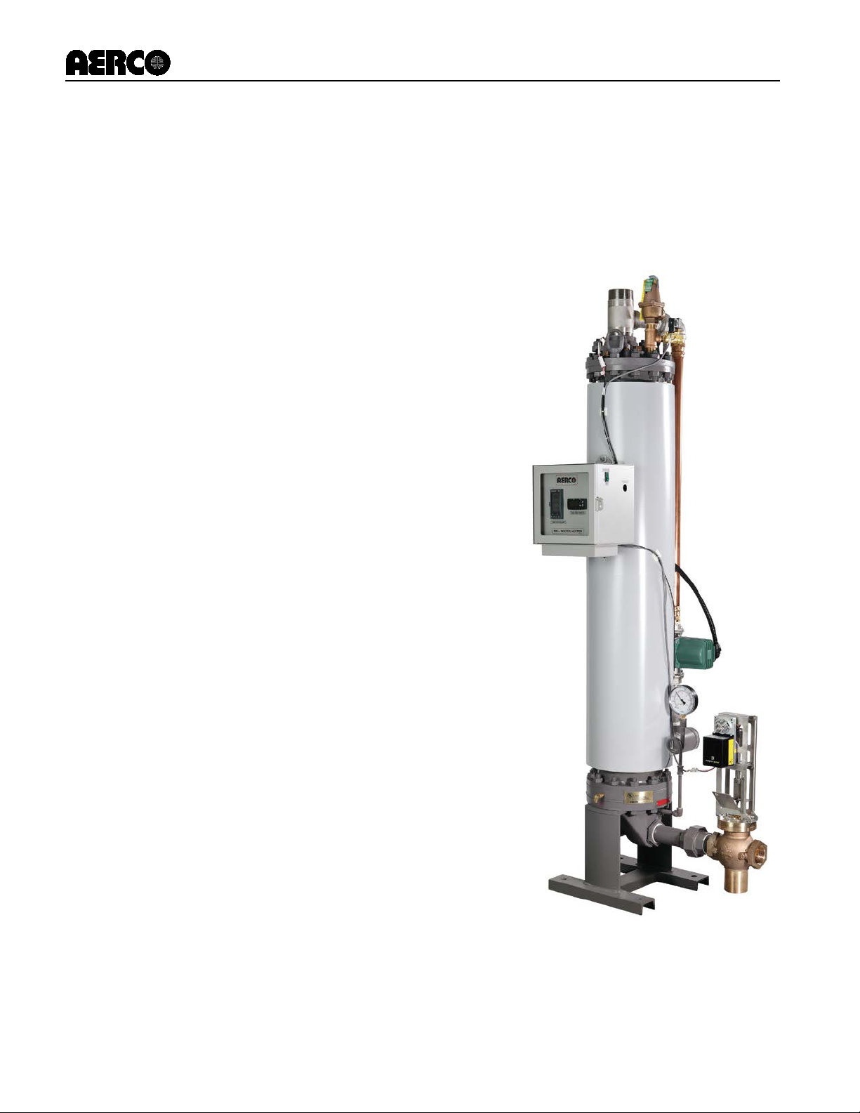
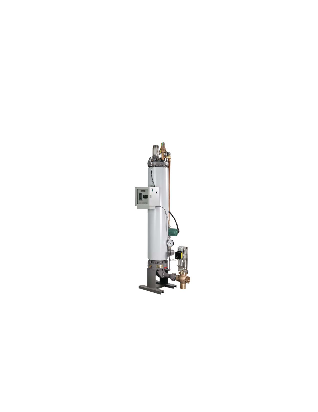
Figure 1-1 illustrates a typical AERCO DW-series heat exchanger.
Figure 1-1. DW-24 Heat Exchanger
This chapter provides a top-level mechanical overview of the DW-series heat exchanger (1.2), its
electronic control s ystem (1.3) and the opt ions and accessories ava ilable from AERCO ( 1.4) for units in
this series
1.2 MECHANICAL OVERVIEW
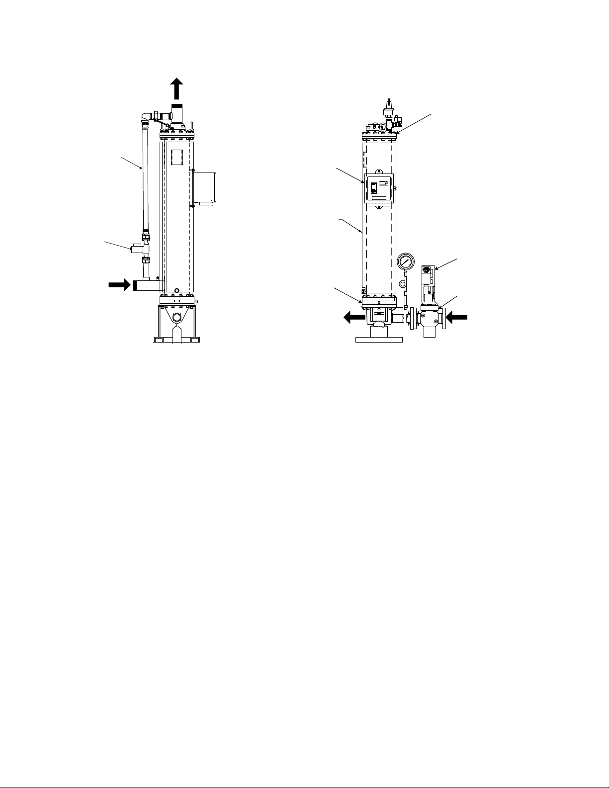
The AERCO double-wall steam-to-water heat exchanger is illustrated in Figure 1-2:
Rev B Mar 2013
Page 8
HE-111 − GENERAL INFORMATION
1-2
AERCO
STEAM INPUT
CONDENSATE OUTPUT
SHELL ENCLOSING THE
TUBE BUNDLE
COLD WATER
INPUT
HOT WATER OUTPUT
CONTROL BOX
RECIRCULATION
PIPING
RECIRULCATION
PUMP
UPPER HEAD ASSEMBLY
CXT-E CONTROL
VALVE
CXT-E ACTUATOR
LOWER HEAD ASSEMBLY
Figure 1-2. Mechanical Overview of the AERCO Double-Wall Steam-to-Water Heat
Exchanger
The DW steam-to-water heat exchanger includes the following principal mechanical parts and
assemblies:
• Shell and upper/lower head assemblies
• Enclosed double-wall tube bundle and tubesheets
• Input/output connections for steam, condensate and h ot/c ol d water
• Control Valve
• Recirculation piping and pump
1.3 ELECTRONIC CONTROL SYSTEM
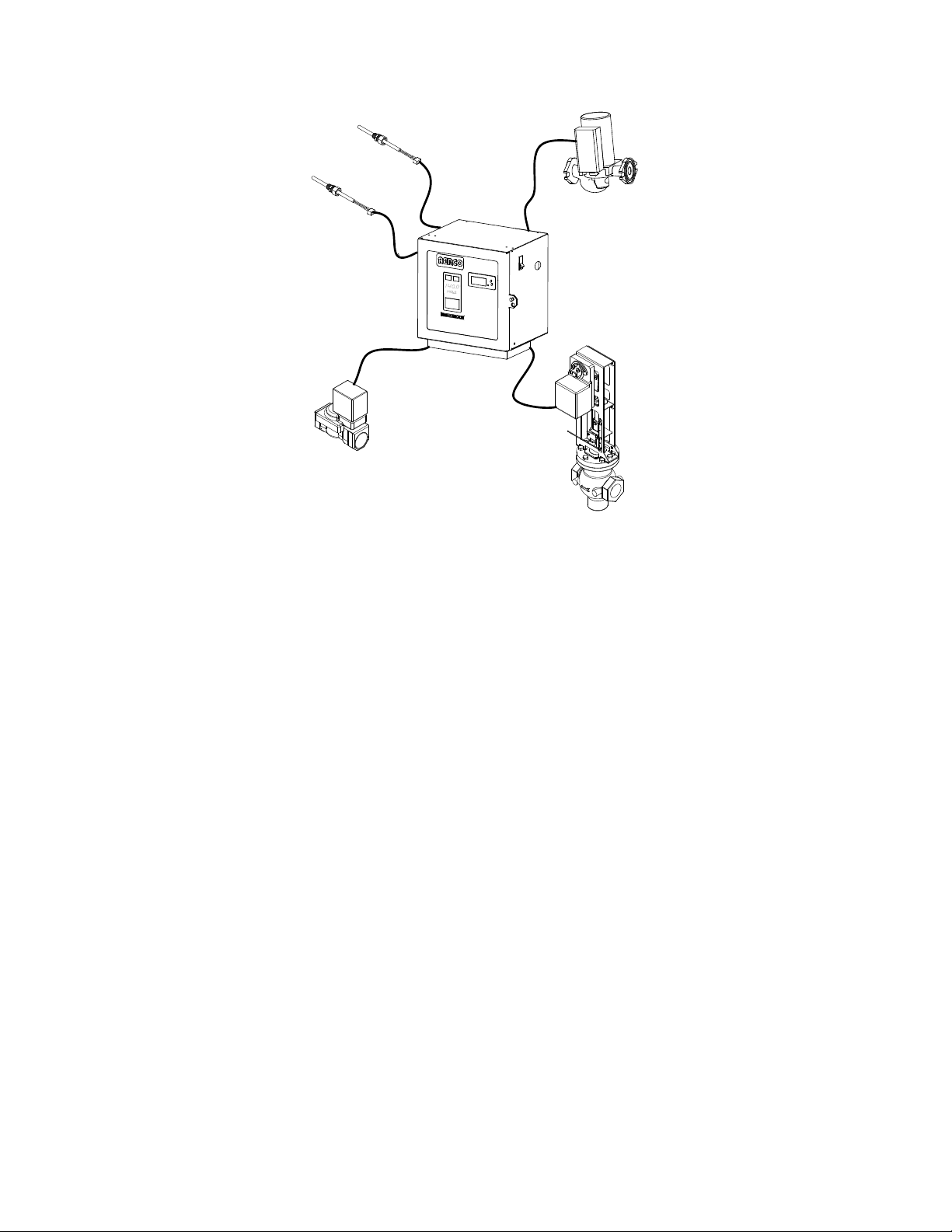
The Electronic Control S ystem (ECS; illustrated in Fig ure 1-3) includes the C ontrol Box components and
associated temperature sensors and actuators. The ECS:
• Controls the temperature of the hot water output to within ±4°F of the Control Box setting under
normal, diversified load conditions (load fluctuations of up to 25% of water heater capacity)
• Shuts down the heat exchanger when the maximum safe water temperature is exceeded
• Relays commands and alarms from/to the MODBUS Communication Option
The ECS and its components are described in Chapter 3.
Rev B Mar 2013
Page 9
HE-111 − GENERAL INFORMATION
1-3
DHW
DUAL OUTLET
TEMP. SENSOR
OVER-TEMPERATURE
SOLENOID VALVE
CONTROL BOX
ASSEMBLY
CONSTANT RATE
RECIRCULATION
PUMP
FEED-FORWARD
MIXTURE TEMP.
SENSOR
CXT-E CONTROL
VALVE ACTUATOR
CONTROL
VALVE
Figure 1-3. Electronic Control System Components
1.4 OPTIONS AND ACCESSORIES
1.4.1 MODBUS Communication Option
The ECS can be ordered with th e MODBUS Communication Opt ion to enable the ECS to be externall y
controlled by an Energy Management System, Building Automation System or computer (supplied by
others).
1.4.2 Accessories
Accessories available for the DW-series steam-to-water heat exchangers equipped with the CXT-E
Electronic Control Valve are listed in
Table 1. Re quired access ories ma y be supplied separatel y by AERCO if the y are not factory-ins talled on
the heater.
The accessories required will depend on the specific application. Detailed installation instructions,
including typical installation drawings are provided in Chapter 2 Installation. Please ensure that ALL
mandatory items are available for installation.
If any of these items have been furnished by AERCO, the necessary drawings and/or instructions are
included with the shipment.
Rev B Mar 2013
Page 10
HE-111 − GENERAL INFORMATION
1-4
Supplied
I. DW-Series Heat Exchanger
Temperature Controller
Yes
Required
Pressure and Temperature Relief Valve
Yes
Required
including:
• Solenoid valve
• Water temperature sensor in heat
exchanger upper head
• Over-temperature indicating switch
required for the application
mounted on steam inlet connection
II. CXT-E Actuator and Valve
Required if a bypass line is used
Table 1. DW-Series Heat Exchanger and CXT-E Actuator/Valve Accessories
Description AERCO
Over-temperature Limit System,
Steam Flow Control Valve, sized as
Compound Steam Pressure Gauge,
Traps No Required
• Drip trap
• Valve trap
• Condensate trap
Vacuum Breaker Yes Required
Yes Required
Yes Required
Yes Required
Remarks
Upstream Shutoff Valve No Required
Downstream Shutoff Valve No
Strainer and Blow-Off Valve No
High Side Pressure Gauge No
Low Side Pressure Gauge, compoundtype for steam flow
No
• Suggested for ease of maintenance
•
Required
Recommended for adjustment and
maintenance
Recommended for adjustment and
maintenance.
Rev B Mar 2013
Page 11

2-1
CHAPTER 2 INSTALLATION
2.1 INTRODUCTION
This chapter provides instructions for:
• Receiving the heat exchanger and installing it in a suitable location (2.2)
• Piping into the steam and water systems (2.3)
• Installing and connecting the Electronic Control System (2.4)
2.2 RECEIVING, UNPACKING AND INSTALLING
To prepare the heat exchanger for installation:
1. Carefully uncrate the heat exchanger.
2. Set the heat exchanger upright us in g a bl ock and tackle or hoist attac he d to t he lifting lugs (eye-bolts)
on the top head.
CAUTION
ALWAYS USE THE LIFTING LUGS to lift and/or move the heat exchanger.
3. To simplify in-place maintenance, install the heat exchanger in a location having the following
clearances:
a. Horizontal clearance: At least two (2) feet all-around
b. Headroom: At least six (6) feet measured upward from the top of the upper shell flange.
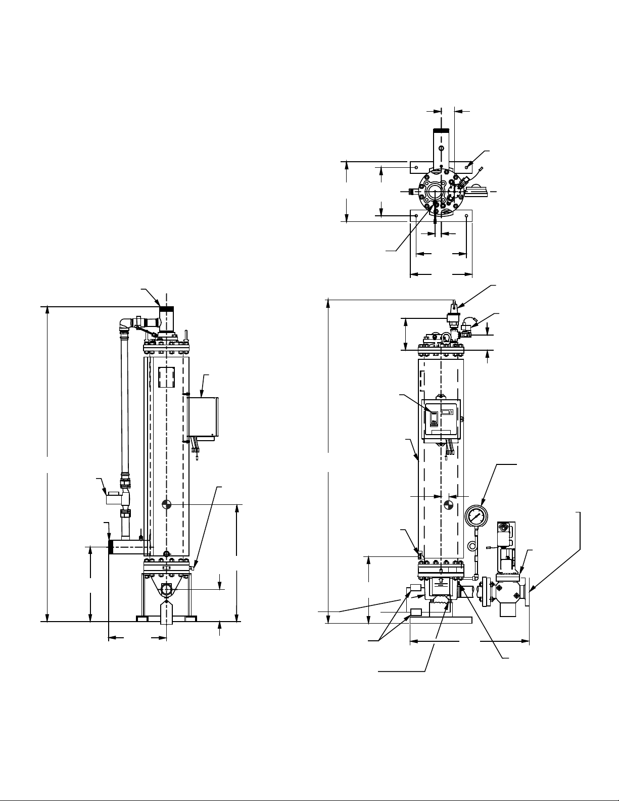
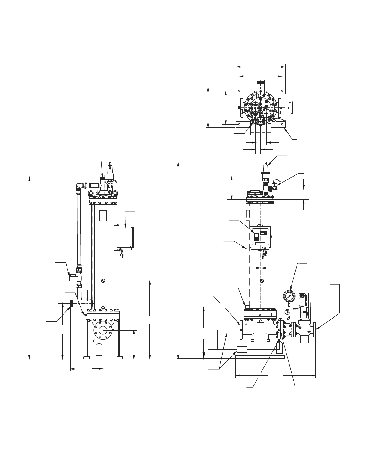
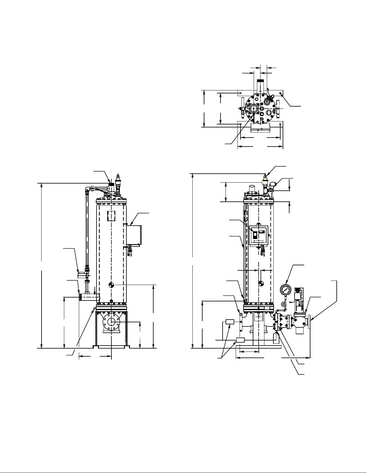
The dimensions of the AERCO Model DW-heat exchangers are presented in Figures 2-1 through 2-3.
4. Secure the heat exchanger in place, pref erabl y, by att aching it to the f loor. If you use pip ing to secur e
the heat exchanger in position, be sure to include ample provision for pipe expansion.
Rev B Mar 2013
Page 12
HE-111 − INSTALLATION
2-2
WIRE TO
COMPONENTS
M
A
N
R
U
N
H
O
L
D
*
83.33
(211.66)
32.18
(81.74)
17.26
(43.84)
COMPOUND
PRESSURE
GAUGE (S/W)
STEAM
INLET
15.44
(39.22)
12.44
(31.60)
13.00
(33.02)
16.00
(40.64)
FOUR .75
(1.91)Ø HOLES
1.63
(4.14)
OUTLET TEMP.
SENSOR
1/2" (1.27)
WATER SOLENOID
2.50" NPT
CONDENSATE
OUTLET
FLOAT & THERMOSTATIC
STEAM TRAP (BY OTHERS)
3/4" PLUGGED
DRAIN
TEMPERATURE
CONTROLLER
1.50 (3.81) THICK
INSULATION
CXT-E
VALVE
VACUUM BREAKER
(STEAM TO WATER)
8.11
(20.60)
3.80
(9.65)
1.75
(4.45)
30.50
(77.47)
18.66
(47.40)
3" NPT COLD
WATER INLET
3" NPT HOT
WATER OUTLET
115 VAC, 2A, 60 HZ
POWER SUPPLY REQUIRED
81.20
(206.25)
9.00
(22.86)
DOUBLE WALL TUBE
LEAK DETECTION PORT
(NOT TO BE PLUGGED)
RECIRC
PUMP
14.90
(37.85)
P&T RELIEF VALVE
1/2" NPT VALVE
TRAP CONNECTION
(STEAM TO WATER ONLY)
2.28
(5.79)
Figure 2-1. AERCO Model DW-24 Heat Exchanger Dimensions
Rev B Mar 2013
Page 13
HE-111 − INSTALLATION
2-3
AERCO
*
1
0
9
0
0
96.20
(244.35)
25.11
(63.78)
11.52
(29.26)
5.22
(13.26)
39.87
(101.27)
VACUUM BREAKER
(STEAM TO WATER)
COMPOUND
PRESSURE
GAUGE (SW)
CXT-E
VALVE
STEAM INLET
3/4" PLUGGED
DRAIN
TEMPERATURE
CONTROLLER
P&T RELIEF VALVE
1/2" (1.27)
WATER SOLENOID
1.00 (2.54)
1/2" NPT VALVE
TRAP CONNECTION
(STEAM TO WATER ONLY)
FLOAT &
THERMOCSTATIC
STEAM TRAP
(BY OTHERS)
4" 150# FLG
CONDENSATE
OUTLET
1.50 (3.81) THICK
INSULATION
FOUR .75
(1.91)Ø HOLES
OUTLET TEMP.
SENSOR
16.50
(41.91)
19.50
(49.53)
21.00
(53.34)
24.00
(60.96)
2.50
(6.35)
2.88
(7.32)
115 VAC, 2A, 60 HZ
POWER SUPPLY
REQUIRED
DOUBLE WALL TUBE
LEAK DETECTION PORT
(NOT TO BE PLUGGED)
27.24
(69.19)
15.97
(40.56)
14.00
(35.56)
36.00
(91.44)
RECIRC
PUMP
WIRE TO
COMPONENTS
3" NPT HOT
WATER OUTLET
89.00
(226.06)
3" NPT
COLD
WATER
INLET
Rev B Mar 2013
Figure 2-2. AERCO Model DW-45 Heat Exchanger Dimensions
Page 14
HE-111 − INSTALLATION
2-4
COMPONENTS
WIRE TO
AERCO
92.70
(235.46)
25.04
(63.60)
10.11
(25.68)
5.75
(14.60)
COMPOUND
PRESSURE
GAUGE (S/W)
STEAM INLET
CXT-E
VALVE
VACUUM BREAKER
(STEAM TO WATER)
39.87
(101.27)
3/4" PLUGGED
DRAIN
1.50" (3.81) THICK
INSULATION
TEMPERATURE
CONTROLLER
FLOAT &
THERMOSTATIC
STEAM TRAP
(BY OTHERS)
10.00 (25.40)
1.00 (2.54)
1/2" (1.27)
WATER SOLENOID
P&T RELIEF VALVE
1/2" NPT VALVE
TRAP CONNECTION
(STEAM TO WATER ONLY)
24.00
(60.96)
21.00
(53.34)
19.50
(49.53)
16.50
(41.91)
OUTLET TEMP.
SENSOR
3.50
(8.89)
3.50
(8.89)
FOUR .75
(1.91)Ø HOLES
87.56
(222.40)
27.16
(68.99)
16.50
(41.91)
36.00
(91.44)
115 VAC, 2A, 60 HZ
ELECTRICAL
POWER SUPPLY
REQUIRED
14.00
(35.56)
3" NPT
COLD WATER
INLET
3" NPT
HOT WATER
OUTLET
DOUBLE WALL TUBE
LEAK DETECTION PORT
4" 150# FLG.
CONDENSATE
OUTLET
RECIRC
PUMP
Figure 2-3. AERCO Model DW-68 Heat Exchanger Dimensions
Rev B Mar 2013
Page 15
HE-111 − INSTALLATION
2-5
TO HEATER
FROM
STEAM
SOURCE
UPSTREAM
SHUTOFF
VALVE
LOW SIDE
PRESSURE
GAUGE
CXT-E ACTUATOR
HIGH SIDE
PRESSURE
GAUGE
DOWNSTREAM
SHUTOFF VALVE
PIPE UNIONS (NOT
REQUIRED WHEN
VALVE IS FLANGED)
STRAINER
TO TRAP &
CONDENSATE
DRAIN
BLOW-OFF VALVE
NOTE:
KEEP PIPING AS SHORT
AS POSSIBLE)
CXT-E CONTROL
VALVE
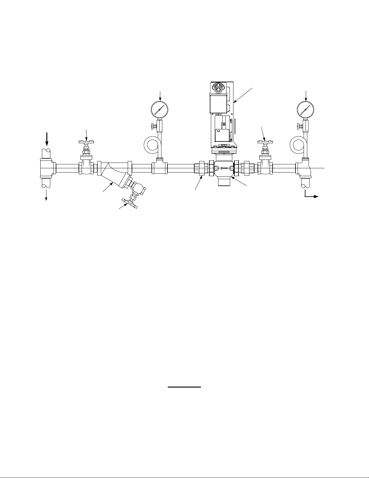
2.3 MAKING THE PIPING CONNECTIONS
Figure 2-4 illustrates the recommended CXT-E Control Valve installation for steam flow.
Figure 2-4. Recommended Control Valve, CXT-E Installation for Steam Flow
1. Install the CXT-E Control Valve with the Actuator linkage in the vertical, upright position, as shown.
2. For maintenance purposes, insta ll pipe unions with threaded e nds t o sim plif y remova l from the s team
line.
3. Blow out all pipe lines to rem ove dirt chips, scale or other for eign matter wh ich could a dversel y affect
Control Valve (“Valve”) operation when in service.
4. Install an in-line strainer upstr eam of the Valve (as illus trated on the left si de of Figur e 2-4) to protec t
against foreign matter entering the Valve during service operation.
5. Ensure that the steam line is properl y trapped to prevent accumulation of condens ate ahead of the
Valve.
6. Install metal-seated, gate-t ype s hutof f va lves ups tre a m and downstream of the Val ve so t hat it ca n be
readily removed from the line for maintenance.
7. Install pressure gauges on both sides of the Control Valve, as shown in Figure 2-4.
8. The high-side pressure gauge is provided for adj ustment and maintenance purposes . The low-side
pressure gauge is intended to ensure that the cor rec t pr ess ur e is available to monitor the operation of
the temperature regulator valve. The low-side pressure gauge measures the pressure of the steam`.
CAUTION
When installing the Valve, DO NOT us e the Ac tuator linkage frame at the top of the Valve
body for leverage. Use pipe wrenches on the inlet and outlet hex of the Valve body.
9. Install the Valve so that the arrow on the Valve body points in the direction of steam flow.
10. After the Valve has been installed in the steam or hot water line, ensure that al l piping connections
are secure and leak-tight.
Rev B Mar 2013
Page 16

HE-111 − INSTALLATION
2-6
The AERCO recommended heat exchanger and Control Valve piping arrangements for single and
parallel heat exchanger installations are presented in Appendix C.
11. For best heat exchanger performance, OBSERVE THE FOLLOWING VERY CAREFULLY when
installing the heat exchanger piping:
a. Do not use cement or red lead when assembling pipe joints.
b. For heat exchanger connec tion types, sizes, and exact locat ions, see Figure 2-1, Figure 2-2 or
Figure 2-3.
c. All piping to the heat exch anger top head should be provided with u nions or flanges LOCATED
BEYOND THE OU TSIDE DIAMET ER OF THE HEAT EXCHANGER H EAD to perm it removal of
the head and shell for in-place maintenance.
d. Include all of the stop va lves, check valves, s team traps, strai ners and other el ements shown in
Appendix C, or as specified separately by AERCO.
e. If the heat exchanger is furnished with the Control Valv e not connected as sho wn in Figure 2-1,
Figure 2-2, or Figure 2-3, mak e the piping bet ween t he Contro l Valve a nd the h eat exchang er as
short as possible, with sufficient unions or flanges included to allow easy Valve removal.
f. Reductions from a pipe to a smaller size connection at the heat exchanger or Control Valve
should be made directl y at the heat exchanger or Valve connection. Expansions f rom a pipe to a
larger size connectio n at the hea t exchan ger or Contr ol Valve should be m ade as far as pr actical
from the heat exchanger or Valve connection.
g. The condensate return p iping must be arranged to p ermit condensate to drain freely by gravity
from the heat exchanger connection. If condensate drain by gravity is not feasible, you may
substitute a pumping steam trap. Refer to the trap manufacturer’s instructions for sizing and
installation procedures.
CAUTION
Failure to provide proper condensate drainage can result in improper
operation of the heat exchanger and/or damage to the heat exchanger
condensate drainage system.
h. All drain discharges ― relief valve, over-temperature solenoid valve and heat exchanger shell
drain ― should be piped directly to a convenient floor drain.
IMPORTANT
Before making final p iping connections to and fr om the heat exchanger
and Control Valve, blow out all piping thoroughly.
2.4 INSTALLING THE CXT-E ELECTRONIC CONTROL SYSTEM
The Control Box and all other Electronic Control System (ECS) components are installed on the heat
exchanger assembly before it is shipped from the factory, so that the ECS installation consists of
connecting AC power t o the Control Box and making the internal power and control connec tions to the
CXT-E Control Valve. Ho wever, if your ECS was ordered with th e MODBUS Com munication option, you
are required to m ake several a dditional c onnections (startin g with step 8, belo w) to enabl e the ECS to be
controlled by an external Energy Management System (EMS), Building Automation System (BAS) or
computer.
Rev B Mar 2013
Page 17
HE-111 − INSTALLATION
2-7
TEMP CONTROLLER
HOLD
RUN
AUTO
MAN
2408
OVER TEMP SWITCH
PANEL
DOOR
CAPTIVE
SCREW
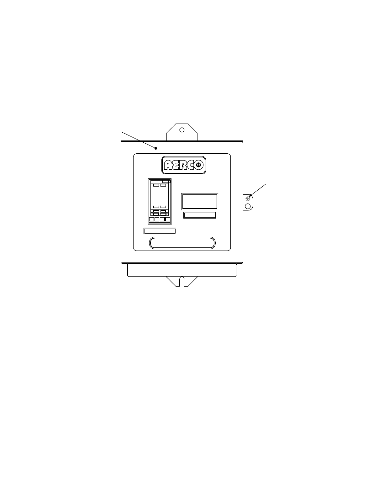
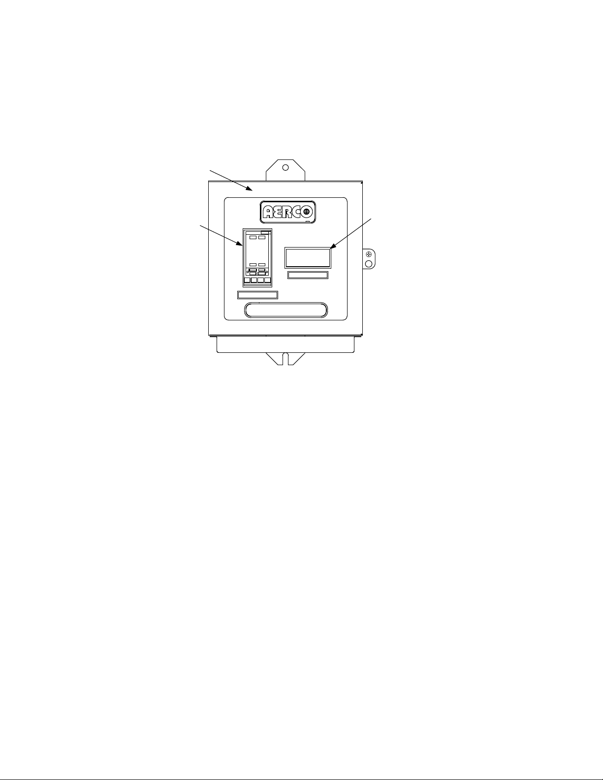
2.4.1 Accessing the Control Box Interior
NOTE
After installing the Contro l Box, you can inst all a lock (not supp lied) on its f ront do or to
prevent unauthorized access to ECS settings.
1. Loosen the captive screw on the Control Box (Figure 2-5) front cover and open the hinged panel
door.
Figure 2-5. ECS Control Panel Front View
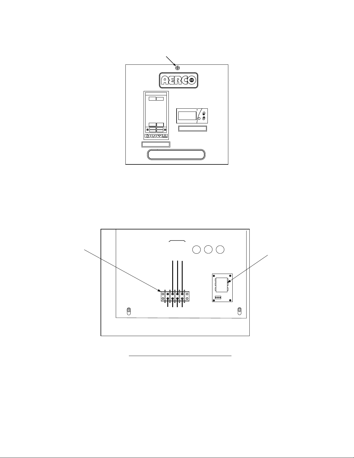
2. Loosen the captive scr ew at the top of the recessed panel (Figure 2-6). Swing down t he recessed
panel to access Terminal Block TB-2 on the bottom interior surface of the Control Box (see
Figure 2-7).
Rev B Mar 2013
Page 18
HE-111 − INSTALLATION
2-8
PANEL CAPTIVE
CONTROL BOX - INTERIOR BOTTOM VIEW
REAR
TB-2
LINE
NEUTRAL
GROUND
100
101
102
GND
FRONT
VOLTAGE
REGULATOR
TERMINAL
BLOCK TB-2
EXTERNAL POWER WIRING
(120 VAC)
SCREW
2408
OP 1
OP 2
SP2
REM
AUTO
RUN
MAN HOLD
TEMP CONTROLLER
TM
Figure 2-6. Recessed Panel Behind Control Box Door
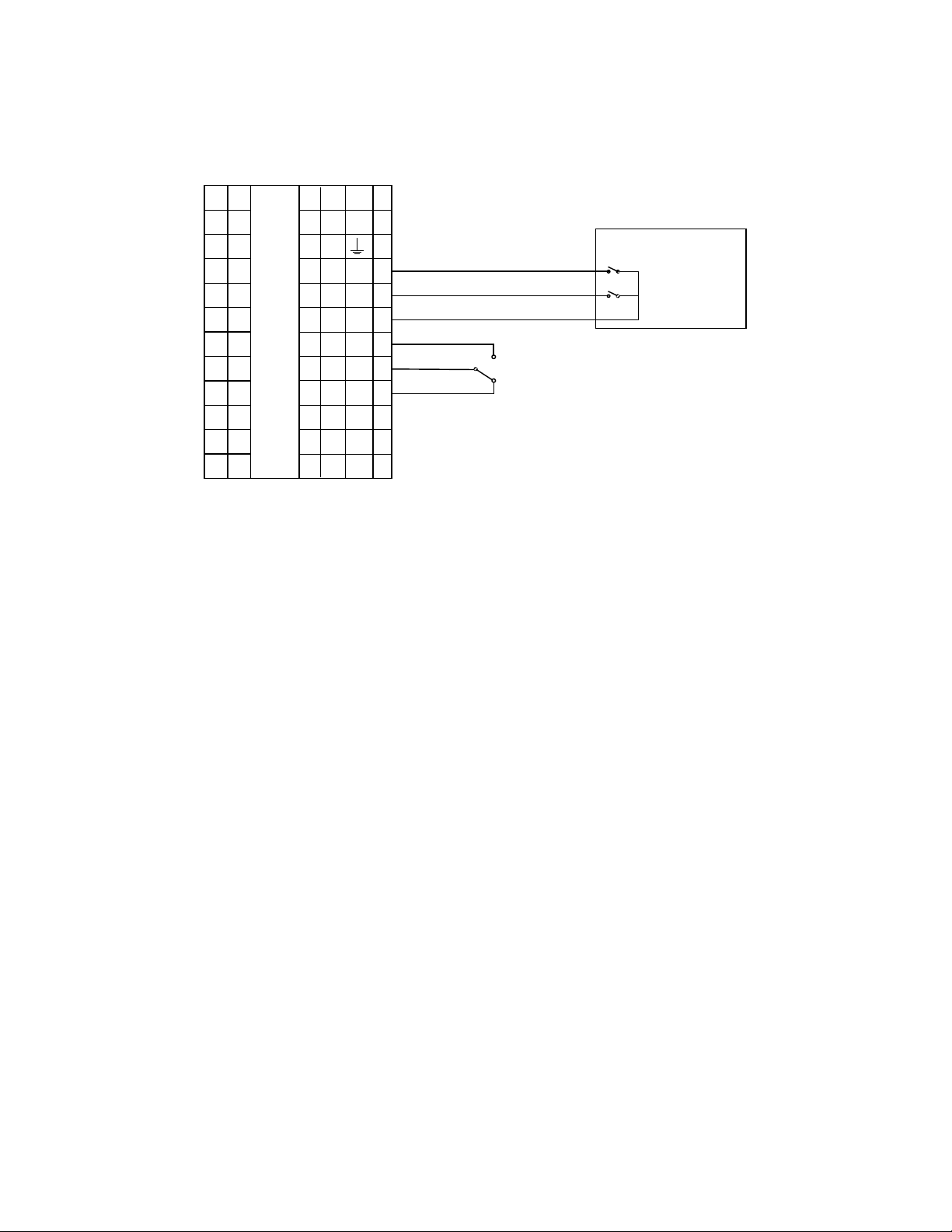
2.4.2 Connecting AC Power to the Control Box
PT.NO.
F
SET
OVER TEMP SWITCH
PT.NO.
3. Feed the external 120 VAC power leads thr ough the cutout labele d “POWER IN” on the rig ht side of
the Control Box.
4. Connect the LINE, NEUTRAL and GROUND leads to the TB-2 terminals shown in Figure 2-7.
Figure 2-7. ECS Control Box AC Power Connections
2.4.3 Wiring the CXT-E Actuator
5. Connect the Control Box cable labeled ACTUATOR to the 3-pin connector plug on the CXT-E
Actuator.
Rev B Mar 2013
Page 19
HE-111 − INSTALLATION
2-9
2408 TEMP. CONTROLLER
COMPUTER CONTROL CABLE
RS232 9-PIN
RS232 25-PIN
RS485
SIGNAL NAME
TERMINAL
SIGNAL NAME
PIN NO.
PIN NO.
PIN NO.
GROUND
HD
GROUND 5 7
GROUND
RECEIVE
HE
TRANSMIT
3 2 A(-)
TRANSMIT
HF
RECEIVE 2 3
B(+)
2.4.4 Verifying Pre-wired Connections
6. Check to ensure that al l pre-wired cable harn ess connec tors an d w ire le ads bet ween the C ontro l Box
and the following ECS components are secure:
• Recirculation Pump
• Over-Temperature Solenoid
• Outlet Dual Temperature Sensor
• Mixed Temperature Sensor
7. If the ECS was ordered with the MO DBUS C omm unication Optio n, proc eed to step 8. Otherwise, the
ECS installation is complete.
2.4.5 Wiring the Temperature Controller to the MODBUS Control System
Step 8, below, applies to the Euro therm, Mode 2408 Tem perature Controller equipped with a MODBUS
communication board and connected to an Energy Management System (EMS), Building Automation
System (BAS) or computer. The type of communication port (RS232-9, RS232-25, or RS485) mounted on
the EMS, BAS or com puter determines the relevant s ignal leads (Ground, Recei ve and Transmit) in the
control cable that you connect to the MODBUS dev ice and the Temperature Contr oller, as described in
Table 2-1.
NOTE
If required, the procedure for adding a communication board to the Temperature
Controller is provided in Appendix A
Table 2-1. MODBUS Communication Signal Connections
8. Refer to Table 2-1, Figure 2-8 and/or the ECS wiring dia gram in Appendix B to wire the Ground (HD) ,
Receive (HE) and Transm it (HF) terminals of the T emperature Controller to the RS23 2-9, RS232-25
or RS485 connector on the EMS, BAS or computer.
Examples of cable types suitable for this purpose are: Belden 9841, 8761, 3105A, or equivalent.
Ensure that the RS232 or RS485 cable connections do not exceed the following lengths:
• RS232 Cable: 50 feet, maximum
• RS485 Cable: 4,000 feet, maximum
NOTE
For best results, DO NO T run MODBU S com m unication wiring in t he sam e c onduit as
power wiring which can couple excessive noise and/or hum into the MODBUS lines.
Rev B Mar 2013
Page 20
HE-111 − INSTALLATION
2-10
1A
HA
1B
HB
1C
HC
2A
2B
1D
HE
HF
HD
3B
3D
3C
2D
3A
2C
JD
JF
JE
JB
JC
JA
LA
LB
LC
AA
AB
AC
VI
V+
V-
Input 1
C
2408 CONTROLLER
L
N
Input 2
MODBUS CONTROL
DEVICE
SHIELDED TWISTED PAIR
Figure 2-8. Cable Connections for Eurotherm 2408 Temperature Controller
2.4.6 Control System Programming Information
Appendix A lists the MOD BUS data addresses for the 2408 C ontroller. The procedures for changing the
Controller address is also provided in Appendix A. Also included are references to the manufacturer’s
handbooks covering the Temperature Controller communication option.
Rev B Mar 2013
Page 21
3-1
CHAPTER 3 FUNCTIONAL DESCRIPTION
COLD WATER
INPUT
HOT WATER OUTPUT
RECIRULCATION
PUMP
3.1 INTRODUCTION
The AERCO DW-series steam-to-water heat exchangers incorporate double–wall heat tubes, in which
steam circulating in a bundle of imm ersed double-wall prim ary tubes heats the s ervice water in the he at
exchanger’s shell. The following Mechanical Description (3.2) briefly discusses how double-wall heat
tubes work and describes each of the principal steam-to-water heat exchanger components. The
Mechanical Description is followed by a discussion of the Electronic Control System (3.3), which regulates
the heat exchanger water tem perature and activat es alarm s and shutdown proce sses in the event s afety
limits are exceeded.
3.2 MECHANICAL DESCRIPTION
3.2.1 Overview
Referring to Figure 3-1, c old service water enter ing the heat exchanger thr ough the Cold Water Input is
dispersed evenly througho ut the heat exchanger shell. As the cold water flows upward, it is heated by
steam circulating through the immersed tube bundle. The heated service water exits through the Hot
Water Output connection in the upper head assembly.
UPPER HEAD ASSEMBLY
RECIRCULATION
PIPING
UPPER
TUBESHEET
LOWER
TUBESHEET
CONTROL BOX
SHELL
LOWER HEAD
ASSEMBLY
CONDENSATE
OUTPUT
AERCO
CXT-E ACTUATOR
CXT-E CONTROL
VALVE
STEAM INPUT
Figure 3-1. AERCO Steam-to-Water Double-Wall Heat Exchanger
The heating steam enters through the CXT-E Control Valve at the bottom of the heat exchanger
assembly and flows thr ough the inner tubes of the double-wall tube bund le. The flowing steam transfers
its heat to the service water contained within the shell, condenses and exits through the Condensate
Output connection.
The flow rate of the heated water varies according to the demand for hot water. The flow rate of the
steam is regulated by the Tem perature Contr oller in th e Control Box so as to maintain the tem perature of
Rev B Mar 2013
Page 22

HE–111− FUNCTIONAL DESCRIPTION
3-2
STEAM
PRIMARY TUBE
INNER WALL
HEATED SHELL-SIDE
SERVICE WATER
PRIMARY TUBE
OUTER WALL
AIR SPACE
the delivered hot water t o within ±4 °F of the Contr ol Box sett ing, un der nor m al, divers ified lo ad con ditions
(load fluctuations of up to 25% of water heater capacity).
3.2.2 Double-Wall Heat Transfer and Water Leakage
As illustrated in Figur e 3-2, the heat exchanger’s prim ary tubes incorporate doubl e-wall construction in
which the inner and outer tube walls are separated b y air space. T he steam flows within the double-wall
primary tubes’ inner walls. Any condensate leaking outward through the inner walls is trapped within
vented air space bet ween the inner an d outer tube wal ls. A ny serv ice water th at l eaks inward t hrough t he
outer tube walls is sim ilarly contained within th e air space. T he accumulated leakage water is conducted
along these air spaces, collected in the bottom head (see 3.2.3.2) and discharged through an
atmospherically vented leak detection port. This construction effectively provides double protection
against primary steam or condensate leaking into the service water, or vice versa. However, it is not
unusual for moistur e to appear at the leak detection port at in itial heat exchanger start-up, even when
there are no tube leaks . This moisture results from water condens ing during the manufacturing proc ess
and being expelled when the system is initially operated.
Figure 3-2. Segment of a Double-Wall Primary Tube
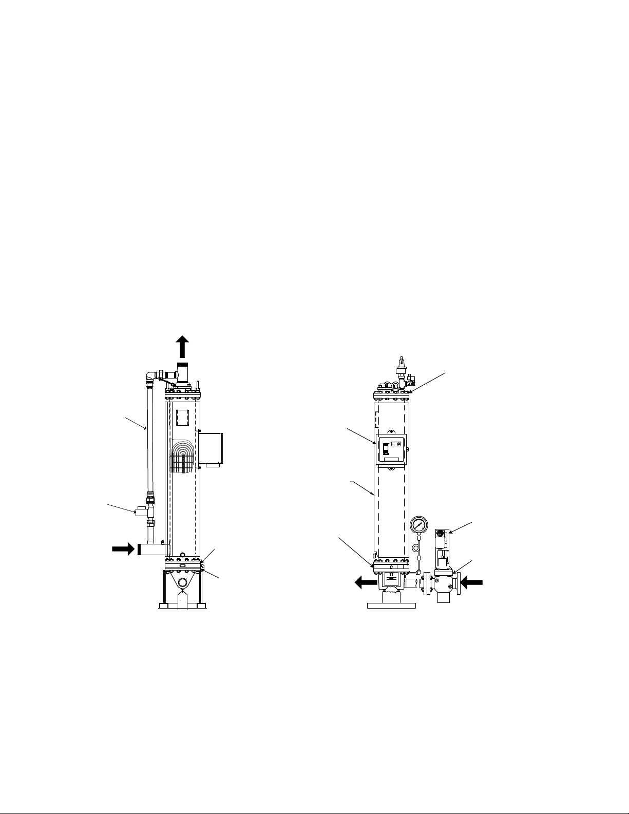
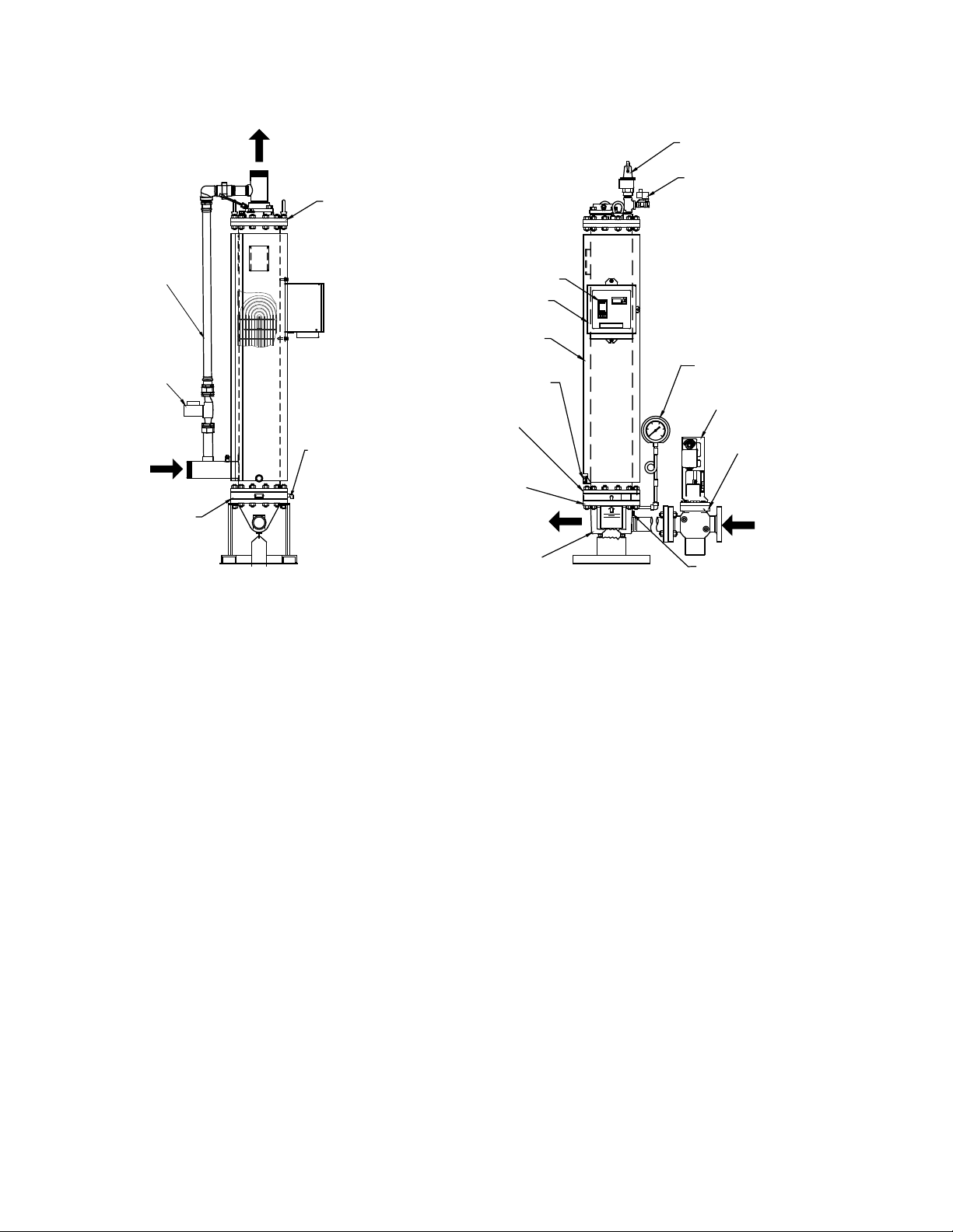
3.2.3 Principal Mechanical Components
The AERCO DW -series heat exchanger cons ists of the following pri ncipal mechanical com ponents (see
Figure 3-3):
• Shell and heads (3.2.3.1)
• Double-wall U-bend tube bundle and tubesheet (3.2.3.2)
• Recirculation pipe and pump (3.2.3.3)
• Electronic CXT-E Control Valve (3.2.3.4)
Rev B Mar 2013
Page 23
HE–111 − FUNCTIONAL DESCRIPTION
3-3
COMPOUND PRESSURE
GAUGE
STEAM INPUT
SOLENOID VALVE
CONDENSATE OUT
PLUGGED DRAIN
TEMPERATURE CONTROLLER
CXT-E CONTROL VALVE
VACUUM BREAKER
PRESSURE AND
TEMPERATURE
RELIEF VALVE
CXT-E ACTUATOR
CONTROL BOX
SHELL
COLD
WATER
INPUT
HOT WATER OUTPUT
LEAK
DETECTION
PORT
RECIRCULATION
PUMP
RECIRCULATION
PIPING
OUTLET MANIFOLD
LOWER SHELL
FLANGE
UPPER SHELL
FLANGE
UPPER HEAD
ASSEMBLY
LOWER HEAD
ASSEMBLY
Figure 3-3. AERCO Double-Wall Heat Exchanger, Model DW-24
3.2.3.1 Shell and Heads
The heat exchanger body incorporates a stainless steel shell, bronze upper head and navy brass
tubesheets, forming a pressure vessel that conforms to ASME standards. The heat exchanger body
encloses the tube bundle and tubesheets.
3.2.3.2 Double-Wall U-Tube Bundle and Tubesheets
The double-wall U-bend copper tubes that conduct steam through the heater shell conform to BOCA
(National Plumbing Co de), IAPMO (Unif orm Plum bing Code) and NAPHC C (National Sta ndard Plum bing
Code), the three nat ional st andards that addr es s doubl e-w all cons tructi on. The o ut er wall of each doubl ewall tube is brazed to the upper tubesheet, and the inner wall is brazed to the navy brass lower
tubesheet. Any tube leak age from the air spaces between the inner and outer walls of the double-wall
tubes accumulates in t he space between t he bottom shell flang es which make up the bottom head. The
accumulated leakage water is discharged through the leak detection port.
3.2.3.3 Recirculation Pipe and Pump
Referring to Figure 3-3, th e recirculation pipe and constant-rate r ecirculation pump deliver a continuous
sample of the heated o utput water to a 1½-inch pipe junction with the Cold W ater Input pipe to reg ulate
steam flow at the Steam Input (see 3.3.2).
3.2.3.4 CXT-E Control Val ve
The CXT-E Control Valve regulates the flow rate of steam into the heat exchanger in response to
positioning control signaling from the Temperature Controller (see 3.3.2). The CXT-E Control Valve
consists of a valve body and linkage to the CXT-E Actuator. The CXT-E Actuator is discussed in 3.3.4.5.
Rev B Mar 2013
Page 24
HE–111− FUNCTIONAL DESCRIPTION
3-4
DHW
DUAL OUTLET
TEMP. SENSOR
OVER-TEMPERATURE
SOLENOID VALVE
CONTROL BOX
ASSEMBLY
CONSTANT FLOW
RECIRCULATION
PUMP
FEED-FORWARD
MIXTURE TEMP.
SENSOR
CXT-E ACTUATOR
CXT-E CONTROL
VALVE
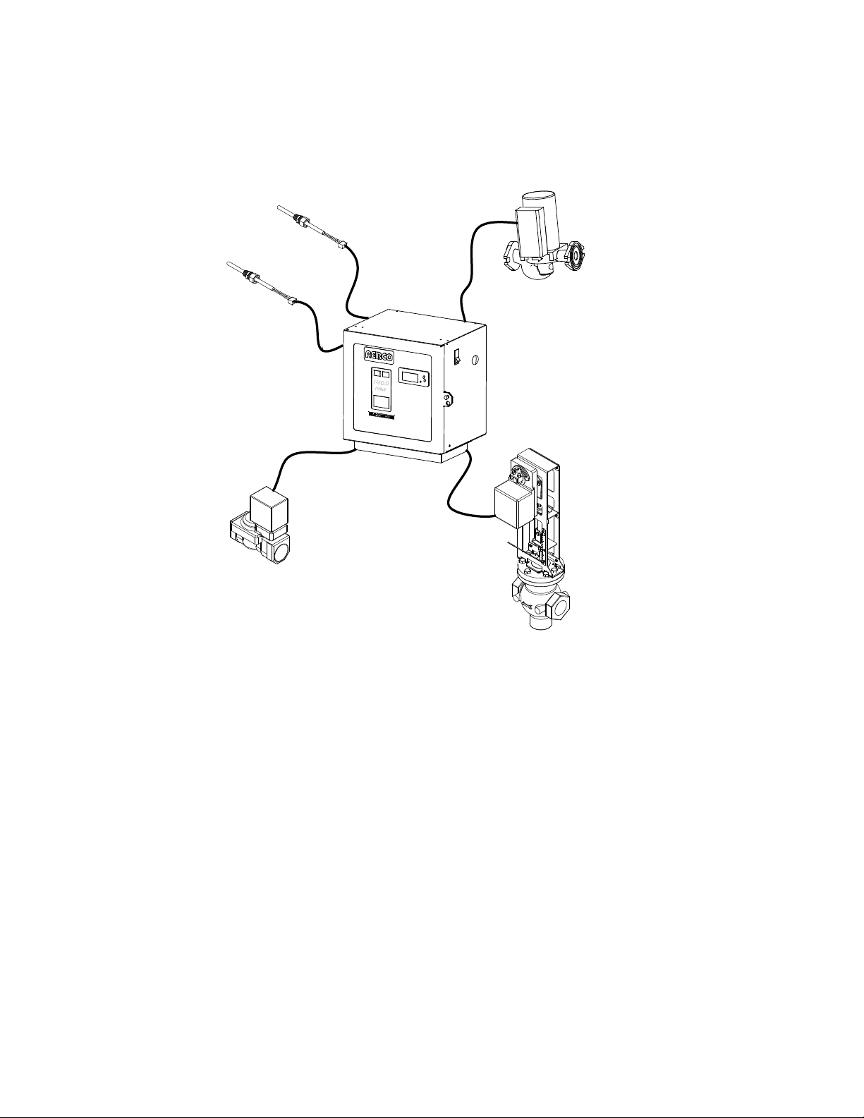
3.3 ELECTRONIC CONTROL SYSTEM
The Electronic Control S ystem consists of the interna l Control Box components and a number of sensor
and safety devices distributed throughout the heat exchanger assembly (see Figure 3-4).
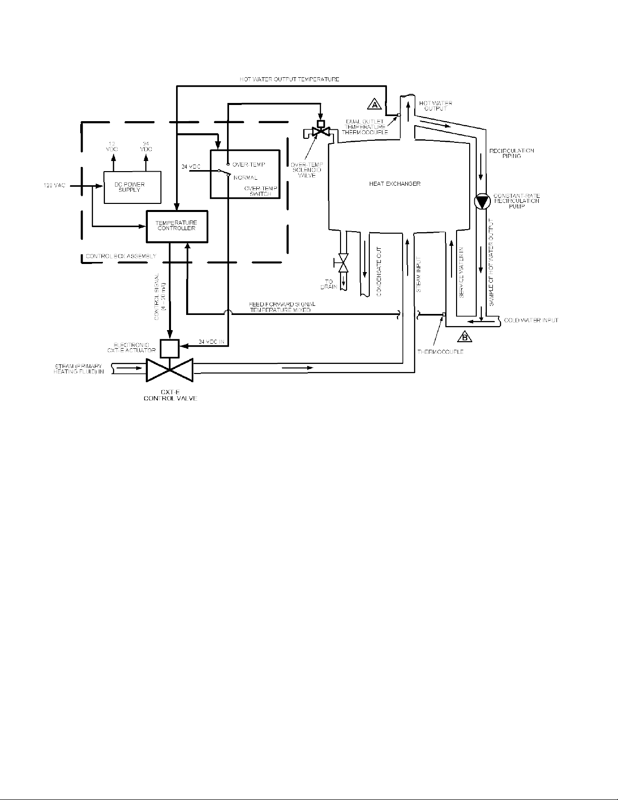
3.3.1 ECS Block Diagram
A simplified block diagram of the ECS is presented in Figure 3-5.
Figure 3-4. Electronic Control System Components
Rev B Mar 2013
Page 25
HE–111 − FUNCTIONAL DESCRIPTION
3-5
Figure 3-5. ECS Simplified Block Diagram
3.3.2 ECS Operational Summary
The ECS adjusts the flow rate of steam into the heat exchanger in response to:
• The water temperature at the Hot Water Output (at A)
• The water temperature of the sampled Hot Water Output mixed with the Cold Water Input (at B)
Changes in hot water dem and vary the flow rate of service water through t he heat exchanger, requirin g
compensating adjustments of the steam flow rate to maintain the service water temperature. To
determine what steam flow rate adjustments are required, the Temperature Controller m onitors (via the
feed-forward signal) t he temperature of a continuous sam ple of output hot water mixed (at B) with th e
cold water input. T he m ixture tem perature cha nges ac cording to the flo w rate of the incom ing cold water,
which in turn depends on the hot water demand.
The Temperature Co ntroller calc ulation of the optimum steam flow rat e into the heat exchanger is based
on a mathematical process known as the Proportional Integral D erivative (PID) algorithm , which accepts
as inputs the measured outlet and inlet temperatures of the system.
3.3.3 Over-temperature Condition
At startup, the operator programs the maximum safe water temperature into the Control Box. During
operation, the Temperature Controller monitors the Hot Water Output temperature to ensure that the
programmed max imum s afe tem per atur e is not ex c ee ded. If it is, t h e T em per ature C ontro ll er opera tes th e
Over-temperature Solenoid Valve (see 3.3.4.4) to relieve excessive temperature buildup in the heat
exchanger.
Rev B Mar 2013
Page 26
HE–111− FUNCTIONAL DESCRIPTION
3-6
TEMP CONTROLLER
HOLD
RUNAUTO
MAN
2408
PT.NO.
OVER TEMP SWITCH
PANEL
DOOR
TEMPERATURE
CONTROLLER
OVER-TEMPERATURE
SWITCH
3.3.4 Principal ECS Components
3.3.4.1 Control Box Assembly
The Control Box Assembly houses the components that monitor heat exchanger temperatures and
operate system controls. The Control Box is illustrated in Figure 3-6. The Control Box components include
the Temperature Controller, Over-temperature Switch and dc Power Supply/Voltage Regulator (not
shown).
Figure 3-6. Control Box Front View
Temperature Controller. The Temperature Controller processes data received from the
temperature and flow se nsors. Using the PID alg orithm, the T emperature Controller c alculates the
optimum steam flow rate to maintain the Hot W ater Output temperature within the programm ed
range. The Temperature Controller translates the optimum flow rate into a 4-to-20 mA control
signal to the CXT-E Control Valve Actuator to adjust the Control Valve opening.
Over-temperature Switch. The Over-temperature Switch compares the output hot water
temperature to the progra mmed high temperatur e limit, typicall y 20°F above the heater setpo int. If
the measured Hot Water Output temperature exc eeds the maxim um setting, the Over -temperature
Switch sounds an a udible alarm and activates t he Over-temperature Solen oid Valve, causing the
overheated water to be dumped from the heater shell. Simultaneously, the Over-temperature
Switch cuts off dc power to the CXT -E Control Valve Actuator, shutt ing off the flow of steam into
the heat exchanger.
DC Power Supply/Voltage Regulator. The dc power supply within the Control Box converts the
120 VAC primary power to 12 VDC and 24 VDC to operate the Control Box com ponents, Overtemperature Switch, Over-temperature Solenoid Valve and the CXT-E Actuator.
3.3.4.2 DHW Outlet Dual Temperature Sensor
The DHW outlet dual temperature sensor consists of dua l thermocouple sensing elements mounted in the
top head. The DHW outlet dual tem perature sensor continuous ly monitors t he service water temper ature
at the Hot Water Output and trans m its it sim ultaneously to bot h the T emperatur e Contro ller and the Ov er temperature Switch in the Control Box.
3.3.4.3 Feed-Forward Mixture Temperature Sensor
The feed-forward m ixture temperature sensor is ins talled in the Cold W ater Inlet nozzle to measure the
mixture temperature of the combined input cold water and the recirculated sample of the Hot Water
Output.
Rev B Mar 2013
Page 27

HE–111 − FUNCTIONAL DESCRIPTION
3-7
3.3.4.4 Over-temperature Solenoid Valve
The Over-temperature Solenoid Valve is operated by the Over-temperature Switch in the Control Box.
When the preset high temperature limit is exceeded at the Hot Water Output, The DHW Outlet Dual
Temperature Sensor s ignals the Over-temperature Sw itch, energizing th e Solenoid Valve and relieving
the temperature build-up in the heat exchanger.
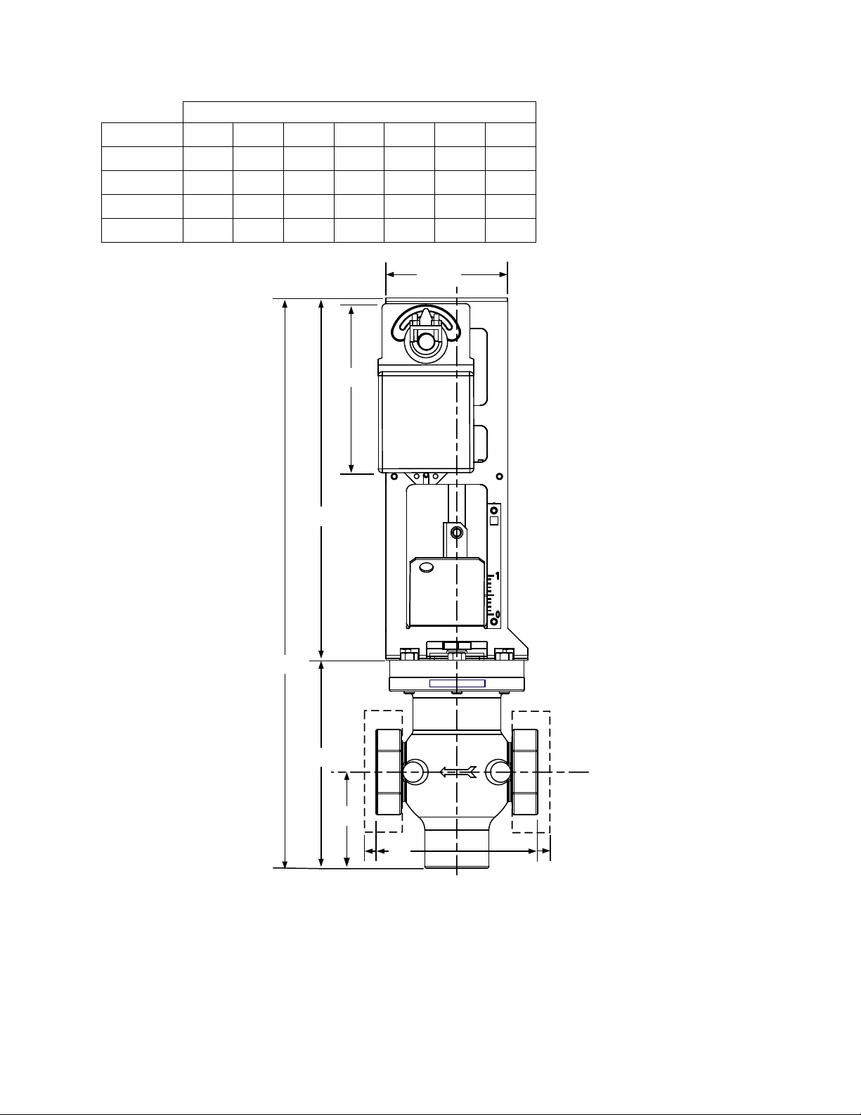
3.3.4.5 Electronic CXT-E Control Valve Actuator
The Electronic CXT-E Actuator operates the CXT-E Control Valve, as discussed in 3.2.3.4. Control
Valves are available in pipe sizes ranging from 1 inch to 4 inches. Figure 3-7 identifies the basic
dimensions for each size Electronic CX T-E Control Valv e. The CXT-E Actua tor is identical for e ach size
valve. The linkage assemblies used with each size valve body are nearly identical, except for minor
differences in the shaft adapter stroke of the mechanical linkage.
Rev B Mar 2013
Page 28
HE–111− FUNCTIONAL DESCRIPTION
3-8
A
B
C
D
13.375
6.60"
4.50"
VALVE SIZES (INCHES)
Dimension 1.00 1.25 1.50 2.00 2.50 3.00 4.00
A 21.12 21.12 21.12 24.25 24.25 24.25 24.25
B 7.75 7.75 7.75 7.75 10.87 10.87 10.87
C 3.56 3.56 3.56 3.56 6.38 6.38 6.38
D 6.00 6.00 6.00 6.00 10.87 10.87 10.87
Figure 3-7. CXT-E Control Valve and Actuator
Rev B Mar 2013
Page 29
AC-105 INSTRUCTIONS - ECS & CXT-E
TEMP CONTROLLER
HOLD
RUN
AUTO
MAN
2408
PT.NO.
OVER TEMP SWITCH
PANEL
DOOR
OVER-TEMP
SWITCH
TEMPERATURE
CONTROLLER
POWER
SWITCH
[
SEE
FIGURE 4-3
CHAPTER 4 ADJUSTMENT
4.1 INTRODUCTION
This chapter explains the procedures you use to adjust the CXT-E Control Valve (“Valve”), Electronic
CXT-E Actuator (“Actuator”) and Electronic Control System (ECS). The ECS is factory adjusted to the
setpoint temperature s pecified on the sales order, and the Actuator is factory adjus ted (auto-stroked) to
ensure that it correctly operates the Valve from the fully-open to the fully-closed positions.
To the extent necessar y, perform all the procedures listed in 4.2 and 4.3 before placing the system into
operation and after replacing the Valve or any ECS components.
CAUTION
BE SURE that all steam shutoff valves are fully closed before performing any of the following
adjustment procedures.
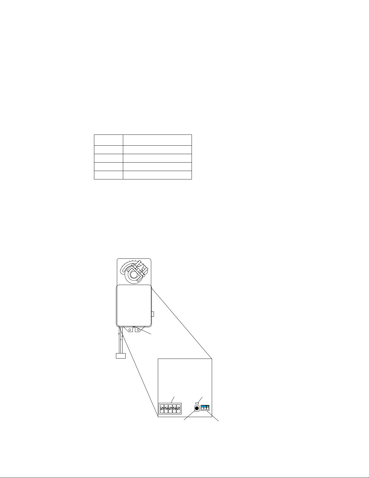
4.2 ADJUSTING THE ELECTRONIC CXT-E ACTUATOR
The Actuator is self-calibrating for all size Valves. The Actuator is power ed b y 24 VDC and contro ll ed b y a
linear 4-to-20 mA control signal, as follows:
• A 4 mA control signal input operates the Valve to the fully-closed position (Valve shaft down)
• A 20 mA signal strokes the Valve to the fully-open position (Valve shaft up).
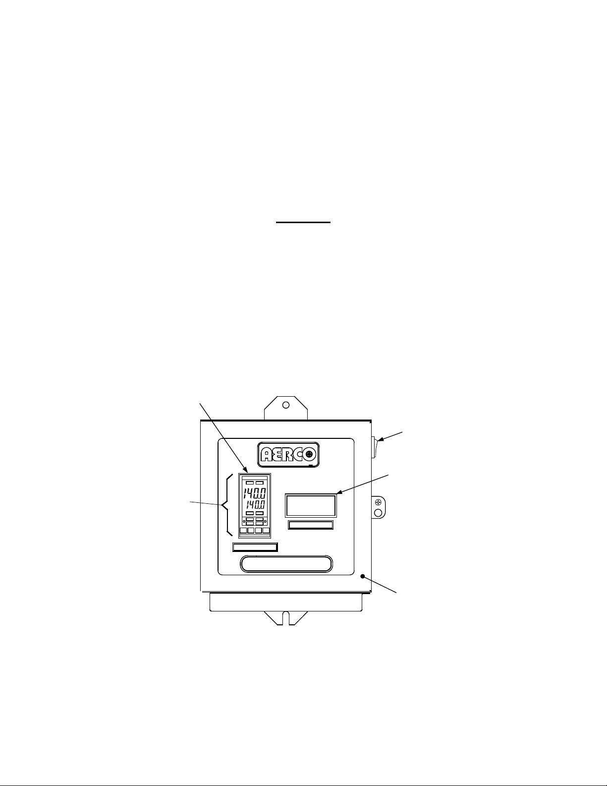
When properly connected t o the ECS, applying po wer to the Control Box applies +24 VDC power to the
Actuator. The power switch is located on the right side of the Control Box, as illustrated in
Figure 4-2.
Figure 4-1. Contr ol Box – Front View
IMPORTANT
Perform this adjustm ent af ter three m onths of use and annual ly there after . Also, t his adjustment is
mandatory each time the Actuator is replaced or when mechanical adjustments are m ade to the
Valve or its linkage.
Rev B Mar 2013 4-1
Page 30
AC-105 INSTRUCTIONS - ECS & CXT-E
1
1”
2
1.25” and 2.5”
3
1.5” and 3”
4
2” and 4”
0
90
neptronic
1 2 3
1 2
3
4 5
1
2
3
DIP SWITCHES (3)
(ALL IN UP POSITION)
AUTO-STROKE
(RESET) BUTTON
LED
TERMINALS
PC BOARD
COVER
SET SCREW
ACTUATOR
Automatically adjust the Actuator as follows:
1. Referring to Figure 4-2, loosen the set screw on the Actuator cover.
2. Remove the Actuator cover to access the PC board containing the terminal connections,
DIP switches, Auto-Stroke (Reset) Button and LED.
3. Referring to Figure 4-1, use the power s witch to tur n on th e Control Box and apply 24 VDC po wer to
the Actuator. (On the terminal strip: pin 2 = +24 VDC, pin 1 = Common) .
The LED will light indicating that power is applied to the Control Box.
4. Wait approximately 10 seconds for the un it to perform its self-test. T he LED will blink f rom one to f our
times, depending on the size of the Valve, as follows:
Blinks Valve Size
5. For full-strok e automatic adj ustment, press the Reset button. T he LED will lig ht and the Actuator will
rotate in both directions to find its open and closed Valve position stops.
6. When the autom atic adjustm ent is complete, the LED will b link f rom one to four tim es, depending on
the size of the valves, as described in step 4, above.
7. Turn the Control Box power off to disconnect power to the Actuator.
8. Replace the Actuator cover and tighten the set screw.
4-2 Rev B Mar 2013
Figure 4-2. Actuator Adjustment
Page 31

AC-105 INSTRUCTIONS - ECS & CXT-E
AUTO
RUN
MAN HOLD
OP 1
OP 2
SP2
REM
2408
UPPER DISPLAY
(DISPLAY HOT
WATER OUTLET
TEMPERATURE)
AUTO SETPOINT
MAN VALVE % OPEN
AUTO/MAN MODE
INDICATORS
AUTO/MAN
PUSHBUTTON
OP1 INDICATOR
ARROW
BUTTONS
LOWER DISPLAY
MODE
DISPLAYS
4.3 ADJUSTING THE ELECTRONIC CONTROL SYSTEM
The ECS is factory set b y AERCO t o the setpoint temperature spec ified on th e sales order. N ormall y, the
over-temperature alar m limit is set 20°F abo ve the specified set point. If no setpoint or o ver-temperature
alarm lim it is specified, the ECS is set to the factory default values of 140 °F (setpoint) and 160 °F (overtemperature alarm limit).
To change the setpoint and over -temper ature alarm lim its, use the controls provided on the T emperatur e
Controller and the Over -temperature Switch. These controls are visible thro ugh t he Control Box f r ont door
window and can be accessed by opening the panel door (Figure 4-1).
4.3.1 Adjusting the Setpoint Temperature
Figure 4-3 illustrates and Table 4-1 describes the Temperature Controller controls and indicators. Use
these controls/indicators to adjust the setpoint temperature as follows:
1. Turn the Control Box power switch on and open the Control Box door.
2. Wait approximately 3 seco nds while the Tem perature Controller performs its self-test. When the test
is completed, the upper display will indicate the current heat exchanger Hot Water Output
temperature, and the lower display will indicate the setpoint temperature stored in memory
(default = 140°F), as illustra ted in Figure 4-3.
3. Ensure that the Temperature Contr oller is s et to the A UT O(m atic ) mode and the AUTO indicat or is lit.
If the MAN(ual) indicat or is lit, pr ess the AUTO/MAN pushbutt on to toggle th e mode sett ing. I ndicator
OP1 should also be lit.
4. Press the ▲ or ▼ arrow buttons, as necessary, to change the disp lay to the desired value.
5. Two seconds after the ▲ or ▼ arrow button is released, the display will blink to indicate that the
Temperature Controller has accepted and stored the displayed value.
Figure 4-3. Temperature Controller
Rev B Mar 2013 4-3
Page 32

AC-105 INSTRUCTIONS - ECS & CXT-E
INDICATOR
Output 1 Indicator
OP1 lights when a 4-to-20 mA signal is supplied to the
OP2
Output 2 Indicator
Not used for the ECS application
SP2
Setpoint 2 Indicator
Not used for the ECS application
active.
AUTO
MAN
reset to 0%.
RUN
HOLD
Scroll Button
Press the Scroll button to select a new parameter in a
list
Down Button
Press the Down button to decrease the value shown in
Table 4-1. Temperature Controller Operating Controls, Indicators and Displays
CONTROL /
OP1
REM
MEANING FUNCTION
Actuator, or when the valve position is above 0%.
Remote Setpoint
Indicator
Auto/Manual Button
and Indicators
Run/Hold Button
and Indicators
REM lights when the ECS is set up to be controlled by
a Remote (MODBUS) signal.
REM will flash when MODBUS communication is
Pressing the button toggles the Controller between the
automatic (AUTO) and manual (MAN) modes.
• AUTO lights when in the automatic mode.
• MAN lights when in the manual mode.
When entering the MAN mode, the Valve position is
Not used for ECS application
Page Button Press the Page button to select a new list of
parameters
the lower display
Up Button Press the UP button to increase the value shown in the
lower displa y
4.3.2 Adjusting the Over-Temperature Alarm Limit
Adjust the over-temperature alarm limit setting using the controls and displays illustrated in Figure 4-4
and described in Table 4-2. Adjust the over-temperature alarm limit as follows:
OVER-TEMPERATURE ALARM LIMIT ADJUSTMENT
The over-temperature alarm limit setting is adjusted using the controls and display on the OverTemperature Switch. The controls and display are illustrated and described in Figure 4-4 and Table 4-2. If
necessary, over-temperature alarm limit adjustment is accomplished as follows:
1. With the Control Box door open, set the ON/OFF POWER switch on the right side to the ON position.
2. Press the SET button on the Over-Temperature Switch. SP will appear in the display.
3. Press the SET button again. The current over-temperature limit value stored in memory will be
displayed (default = 160°F).
4-4 Rev B Mar 2013
Page 33

AC-105 INSTRUCTIONS - ECS & CXT-E
INDICATOR
MEANING FUNCTION
LED Display
TEMP status
Displays current water temperature or setpoint.
RST
RESET Button
Resets the unit after an alarm condition.
UP Button
Increases the displayed temperature.
DOWN Button
Decreases the displayed temperature.
SET
SET Button
Used to access and store parameters in the unit.
4. If the display does not sh ow the desired over-temperature alarm setting, press the ▲ or ▼ arrow
button to change the display to the desired temperature setting.
5. Once the desired over-temperature alarm setting is displayed, press the SET button to store the
setting in memory.
6. To exit the programming mode, press the SET and ▼ buttons simultaneously, or simply wait one
minute.
7. Once the programming mode has been exited, the display will show the current outlet water
temperature of the Heater.
Figure 4-4. Over-Temperature Switch
Table 4-2. Over-Temperature Switch Controls and Indicators
CONTROL or
Rev B Mar 2013 4-5
Page 34

HE-111 − ADJUSTMENT
4-6
This page intentionally left blank.
Rev B Mar 2013
Page 35

5-1
CHAPTER 5 OPERATION
5.1 INTRODUCTION
This chapter provides instructions for:
• Preparing your heat exchanger and Electronic Control System (ECS) for operation (5.2)
• Turning on the heat exchanger and setting it to run automatically (5.3)
• Shutting down and draining the heat exchanger (5.4)
5.2 PRE-OPERATIONAL
1. Refer to Chapter 2 Installation and verify that:
a.Electrical power is properly connected to the ECS and the CXT-E Control Valve.
b.All piping connections have been made according to recommended configurations.
c. All connecting piping has been cleaned (blown) out.
2. Refer to Chapter 4 Adjustments and ver ify that the T em perature Control ler setpo int (4.3.1) and Overtemperature Switch alarm limit (4.3.2) have been set properly.
5.3 STARTUP PROCEDURES
1. Referring to Figure 5-1, press the power switch on the r ight side of the C ontrol Box to appl y power to
both the Electronic Control System (ECS) and the CXT-E Control Valve. When power is initially
applied, the Temperature Controller automatically performs a self-test sequence for approximately
three seconds.
2. When the self-test is complete, the Temperature Controller will show the present hot water outlet
temperature in the upper display and the setpoint temperature in the lower display.
3. Set the temperatures to the desired setpoints on the Over-temperature switch and the Eurotherm.
4. Set the Eurotherm into the Man mode and set the Valve position to 0%. If the temperature in the
heater increases, see Chapter 7 Troubleshooting.
5. Open the stop valve in the C old Water Input line and h old t he relief valve in t he heat exchanger upper
head assembly open to enable air to escape (to avoid an air poc ket build-up which coul d prevent the
heat exchanger from f illing with water ) . When water flo ws out of t he relief valve, the heat exchanger is
full.
6. Open an y stop valves in th e building or proc ess recirculat ion system , if such a s ystem is inc luded in
the Heater installation.
7. Open the sto p valve in t he Hot W ater Output l ine. Open hot water fauc ets or va lves in the building or
process to ensure a flow of water through the heat exchanger.
8. Slowly open all stop valves in the Steam Input and Condensate Output lines. If double block and
bleed valving is used, make sure that the drain (bleed) valve is closed tight.
IMPORTANT
To prevent a possible over-temperature condition during initial start-up, be sure to
perform the following steps in the order specified:
Rev B Mar 2013
Page 36

HE-111 − OPERATION
5-2
TEMP CONTROLLER
HOLD
RUNAUTO
MAN
2408
PT.NO.
OVER TEMP SWITCH
PANEL
DOOR
OVER-TEMP
SWITCH
TEMPERATURE
CONTROLLER
POWER
SWITCH
[
WATER TEMPERATURE AT
HOT WATER OUTLET
SETPOINT TEMPERATURE
AUTO
RUN
MAN HOLD
OP 1
OP 2
SP2
REM
2408
UPPER DISPLAY
LOWER DISPLAY
AUTO/MAN MODE
INDICATORS
AUTO/MAN
PUSHBUTTON
OP1 INDICATOR
ARROW
BUTTONS
Figure 5-1. Contr ol Box
9. Referring to Figure 5-2, press the AUTO/MAN pushbutton to toggle the AUTO/MAN display to the
10. The upper display will continue t o show the cur rent heat ex chan ger out let w ater temperature, and the
11. Using the ▲ arrow button, set the CXT-E Control Valve to the 10% position and monitor the heat
12. Continue to open the valve further in 5% increments until the Hot Water Output temperature begins to
13. When the Hot Water O utput water temper ature has increased to with in 20°F of the desired setp oint,
Rev B Mar 2013
MAN (Manual) mode. The MAN indicat or will light.
Figure 5-2. Temperature Controller
lower display will show the position of the CXT-E Control Valve Actuator in %. When the Manual
mode is initially selected, the lower display will show 0%, indicating that the Control Valve is fully
closed.
exchanger Hot Water Output water temperature.
increase at a moderate rate.
press the AUTO/MAN button to set the Temperature Controller to the AUTO mode. The AUTO
indicator will lig ht and the MAN ind icator will go off. When the T emperature C ontroller is in the AUTO
Page 37

HE-111 − OPERATION
5-3
mode, the upper display will continue to show the heat exchanger Hot Water Output water
temperature, and the lower display will show the selected setpoint temperature.
14. In the AUTO mode, the ECS will stabilize at th e selected setpoint tem perature. When stabilized, t he
ECS is set for unattended operation and no further operator intervention is required.
15. Close the Hot Water faucets or valves that were opened in step 7.
5.4 SHUTTING DOWN AND DRAINING THE HEAT EXCHANGER
To shut down the heat exchanger:
1. Set the Eurotherm to the MAN(ual) in the 0% Valve position.
2. Close all stop valves in the Steam Input and Condensate Output lines.
3. IN THIS ORDER, close the stop valves in the:
a. Hot Water Output line
b. Recirculation line
c. Cold Water Input line
When the heat exchange has been shut down accor ding to steps 1 and 2, drain the heat exchanger as
follows:
4. CAREFULLY open the relief valve in the heat excha nger upper head assembly to r elieve pres sure in
the heat exchanger shell. If water continu es to flow from the relief valve, one of the cold water stop
valves is either leaking or is not shut tightly. Stop the flow from the relief valve and proceed.
5. Holding the relief valve open (to prevent creating a vacuum in the she ll), open the plugged drain at
the bottom of the heater exchanger shell and drain the heat exchanger completely.
Rev B Mar 2013
Page 38

HE-111 − OPERATION
5-4
This page intentionally left blank.
Rev B Mar 2013
Page 39

6-1
CHAPTER 6 SCHEDULED MAINTENANCE
INDICATOR
PLATE
VALVE
TOP
PACKING
NUT
P/O LINKAGE
ASSEMBLY
LOWER
SHAFT
6.1 INTRODUCTION
This chapter lists the preventive maintenance procedures recommended for the heat exchanger and
Electronic Control System (ECS). These recommendations include procedures to be performed each
week (6.2), month (6.3), quarter (6.4), six-month interval (6.5) and year (6.6).
The recommended preventive maintenance schedule is summarized in Table 6-1 at the end of this
chapter.
6.2 WEEKLY MAINTENANCE
□ Tube Leaks
Check the leak detection tube once each we ek for evidence of leaks in th e heat exchanger tubes.
MAKE CERTAIN T HAT THE DETECT ION TUBE NEVER GET S PLUGGED. If any flui d is escaping
from the detection tube, shut do wn the he at ex c hang e r as out li ned i n Section 5.4 and see Section 9.2
to investigate the leak.
6.3 MONTHLY MAINTENANCE
□ Steam Strainer
After the first month of operation, cle an the strain er in the Steam Input line in ac cordance with the
instructions furnished with the strainer.
□ CXT-E Control Valve
Check the CXT-E Control Valve (“Valve”) for leaks, as follows:
1. Referring to Figure 6-1, check the packing nut and Valve top for evidence of leakage.
Figure 6-1. Valve Shaft Seals
2. If there is leakage between the pac king nut and Valve top, tighten the packing nut unt il the leakage
stops. DO NOT FORCE the packing nut.
Take care not to over -tighten t he packing n ut to avoid tr apping the va lve
stem and slowing or stopping Valve motion.
CAUTION
3. If tightening the packing nut does not s top the leak, the pack ing nut and packing assembly m ust be
replaced in accordance with the procedures specified in Sections 8.2.2 and 8.2.3.
Rev B Mar 2013
Page 40

HE-111 − SCHEDULED MAINTENANCE
6-2
6.4 QUARTERLY MAINTENANCE
6.4.1 First Three Months
□ Accumulated Shell Solids
After the first three months of initial operation, drain the heat exchanger as follows:
1. Close all stop valves in the Steam Input and Condensate Output lines.
2. IN THIS ORDER, close the stop valves in the:
a. Hot Water Output line
b. Recirculation line
c. Cold Water Input line
3. CAREFULLY open the relief valve in the upper he ad assem bly to relieve pressure in th e shell. If fluid
continues to flow from the relief valve, one of the Cold Water Input stop valves is either leaking or is
not completely shut off. Securely close all Cold Water Input stop va lves until there is no mor e flow
from the relief valve.
4. WITH THE RELIEF VALVE HELD OPEN (to prevent creating a vacuum in the shell), open the
plugged drain at the bottom of the shell (see Figure 3-3), and drain the heat exchanger completely.
5. Examine the water being drained.
a. If the am ount of solids in the water being drained ap pears to be heavy, set a schedule to drain
the heat exchanger every 3 months.
b. If the amount of solids appears to be light, set a schedule to drain the heat exchanger every 6
months.
c. Even if the am ount of s olids appears to be v er y light o r not at all, set a sche dule t o drai n the heat
exchanger at least once eac h year.
6. To refill the heat ex changer and place it b ack into operation, replace the drain plug an d perform the
Pre-Operational and Operational steps l isted in Chapter 5.
6.4.2 Each Quarter
□ Valve Calibration
Refer to 4.2 and perform the CXT-E Actuator adjustment procedure as instructed.
□ Over-temperature Switch
Check the operation of the Over-temperature Switch as follows:
1. Refer to 4.3.2 and lower the over-temperature setting to approximately 5°F below the present
setpoint, as shown in the lower display of the Temperature Controller.
2. Verify that an over-temperature alarm is generated and the following events occur:
a. The CXT-E Control Valve closes.
b. The Over-temperature Soleno id (located at top of heat exchan ger) opens and e xpels water fr om
the system.
c. The Over-temperature Switch generates an audible alarm.
3. When you have successfully completed the over-temperature alarm check, return the Overtemperature Switch to its original setting.
Rev B Mar 2013
Page 41

6-3
6.5 SEMI-ANNUAL MAINTENANCE
□ Actuator
Refer to Section 4.2 and perform the Actuator adjustm ent procedure presented ther e. Verify that
the Actuator strokes the Control Valve from the fully closed to the fully open position.
□ Temperature Controller
Check the Temperature Controller operation at least every 6 months. Make any necessary
adjustments per Secti on 5. 3, steps 7 through 11.
□ Steam Strainer
Clean the strainer in the Steam Input line in accordance with the instructions furnished with the
strainer.
6.6 ANNUAL MAINTENANCE
□ Temperature Sensors
AERCO recomm ends that you check the temperature sensors once a year to ensure that there is
no scale build-up or clogging that may degrade system operation. To check the temperature
sensors, proceed as follows:
HE-111 − SCHEDULED MAINTENANCE
1. Close the upstream and downstream water supply valves to the heat exchanger.
2. Check the DHW Outlet Temperature Sensor at the Hot Water Output port. If necessary, clean it using
the following procedure:
a. Disconnect and remove the DHW Outlet Temperature Sensor (dual thermocouples).
b. Inspect for evidence of scale buildup on the stainless steel sleeve.
c. If necessary, clean the thermocouples using a wire brush.
3. After cleaning, reinstall both thermocouples and ensure the y are tight ene d securely.
4. Open all valves that were closed in Step 1 and res tore the heat exchanger to operation.
□ Recirculation Pump
The recirculation pump is located in the recirculation line, just above the Cold Water Input.
1. Turn the power switch on the Control Box to OFF.
2. Ensure that the water has been drained from the unit (see 6.4.1, steps 1-4).
WARNING
BEFORE PERFORMING THE FOLLOWING STEPS, ENSURE THAT
THE POWER SWITCH ON THE SIDE OF THE ECS CONTROL BOX IS
OFF AND THE HEATER HAS BEEN DRAINED AS SPECIFIED IN
6.4.1, STEPS 1 THROUGH 4.
3. Locate the recirculation pump and disconnect the flanges from the recirculation piping.
4. Without pulling on the e lectrical conduit attached to the recirculation p ump, carefully s lide it out and
inspect it.
Rev B Mar 2013
Page 42

HE-111 − SCHEDULED MAINTENANCE
6-4
□
□
□
□ Shell Solids*
□
□
□
□
□ Over-temperature Switch
□
□
5. If there is evidence of sc ale build-up, disconnect the condu it and el ectric al power lines f rom the pump
and service or replace it, as necessary.
6. If there is no evidence of s cale build-up on the recirculation pump, r einstal l it an d r ec onnect t he wiring
and flanges.
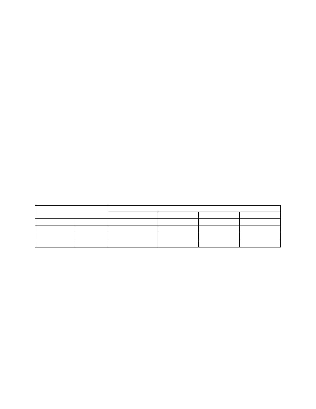
Table 6-1. Recommended Maintenance Schedule
Maintenance Check Week
Tube Leak
Control Valve Leak
Vacuum Breaker(s)
Over-temperature Switch Alarm
Temperature Controller
Actuator Adjustment
Steam Strainer
Temperature Sensor
Month
(6.3)
√
√
√
√
√
√
√
√
√
√
(6.4)
Quarter
(6.5)
Six Months
(6.6)
Year
(6.7)
Recirculation Pump
* Perform the first test for shell solids upon com pletion of the first three m onths of heat exchanger
operation. Depending upon the results (see 6.4.1, Step 5), repeat this test quarterly, semiannually or annually.
Rev B Mar 2013
√
Page 43

7-1
CHAPTER 7 TROUBLESHOOTING
7.1 INTRODUCTION
This section provides you with troubleshooting proc edures for isolating faults t o the most probable cause
whenever malfunctions occur in the heat exchanger (Table 7-1), CXT-E Electronic Control Valve
(Table 7-2), or Electronic Control System (ECS; Table 7-3). Table 7-4 provides troubleshooting tips for
correcting control s ystem faults, and Table 7-5 provides the d ynamic temperature control settin gs for the
three models of the DW-Series water heater product line.
Before performing the tr oubleshoot ing steps and pr ocedures pr ovided in T ables 7-1 throu gh 7-4, com plete
the following preliminary checks:
1. ELECTRONIC CONTROL VALVE, CXT-E a. Verif y that all piping conne ctions have been made in accordanc e with Figure 2-4 and that all
electrical connections have been made in accordance with Figure 2-7.
b. Ensure that the Electronic Control Valve (“Valve”) is installed with the flow arro w on the Valve
body pointing in the direction of flow.
c. Ensure that both the upstream and downstream shutoff valves are fully open.
2. ELECTRONIC CONTROL SYSTEM
a. Ensure that all ECS electrical cable connections are secure.
b. Ensure that the CXT-E Control Valve actuator is connected to the Control Box cable plug.
NOTE
When system m alfunctions occur, check the troubles hooting sections of the manuals
for any other equipment included in this installation, as necessary, in addition to the
procedures provided i n this section. Appendix A of this manual contains process fault
and diagnostic alarm information for the Eurotherm, Model 2408 Temperature
Controller.
7.2 TROUBLESHOOTING PROCEDURES
When a heat exchanger fault occurs, proceed as follows:
1. Refer to the FAULT INDICATION column in the following tables and locate the fault that best describes the existing conditions.
2. Proceed to the PROBABLE CA USE column. If m ore than one item is listed, start with the f irst item shown for the fault condition.
3. Perform the corresponding check s and proc edures list ed in the C ORRECT IVE A CT ION colum n for the first PROBABLE CAUSE.
4. Continue checking each additio nal PROBABLE CAUSE for the existing fault u ntil the fault has been corrected.
5. If component removal and /or replacem ent is required, refer to the appl icable procedures in Chapter 8 Corrective Maintenance.
Rev B Mar 2013
Page 44

HE-111 − TROUBLESHOOTING
7-2
Table 7-1. TROUBLESHOOTING – HEAT EXCHANGER
NO. FAULT INDICATION PROBABLE CAUSE CORRECTIVE ACTION
T1 The heat exchanger
does not maintain the
required temperature
at rated capacity.
1. The Control Valve does not open.
2. There is a leak in either the inside or outside
wall of one or more of the heat exchanger
tubes, as indicated by a flow from the leak
detection port.
3. Recirculating pump failure.
4. The heat exchanger tubes are scaled up.
5. The heat exchanger is being used at a rate
higher than its design capacity.
6. Steam pressure is too low.
7. Condensate is backing up into the heat
exchanger because of a restriction in the
condensate drain line.
8. The condensate return piping has not been
installed so as to enable the condensate to
drain freely by gravity, and/or the condensate
check valve leaks or has failed.
9. Thermocouple is not installed in the water flow.
10. The Temperature Controller reads wrong.
1. Check the instructions in Table 7-2.
2. Refer to Cha pter 9, secti on 9.2, and proceed as instructed.
3. Proceed as follows:
a. Check input power to the re c irc ulation pump.
b. Check the temperature of the copper tube above the pump.
It should be the same as the outlet DHW temperature. If
cold, repair or replace the pump, as needed.
4. Contact AERCO or your nearest AERCO representative.
5. Contact AERCO or your nearest AERCO representative.
6. Check the supply pressure gauge ahead of the Control Valve. If
the reading is low, adjust the steam supply pressure to the
required value. If the steam supply line is restricted, the gauge
reading will drop excessively when the heat exchanger calls for
full steam, even though the pressure seems to be normal when
the load is light. If the steam supply pressure is correct, the
steam pressure compound gauge reading should reach design
pressure for steam in the heat exchanger tubes as the Hot
Water Output temperature starts to drop. If it does not, check
the operation of the Control Valve.
7. Contact AERCO or the nearest AERCO representative for the
trap size required and make the necessary correction.
8. If necessary, rearrange the condensate return piping to permit
condensate to drain freely from the heat exchanger connection.
Inspect the condensate check valve and replace it if it is leaking
or has failed. Also, ensure that there is no restriction in the
condensate drain line.
9. Check to ensure that the thermocouple sheath does not
protrude more than ½“ from the compression fitting.
10. Check by replacing the Temperature Controller with one known
to be correct.
Rev B Mar 2013
Page 45

HE-111 − TROUBLESHOOTING
7-3
Table 7-1. TROUBLESHOOTING – HEAT EXCHANGER, continued
5. The Steam Input does not c lose.
5. Check the instructions in Table 7-2, Item T11.
NO. FAULT INDICATION PROBABLE CAUSE CORRECTIVE ACTION
T2 Heat exchanger
overheats
T3 Hot water outlet
temperature
fluctuates widely
1. Temperature Controller is indicating the wrong value.
2. Water is preheated too hot.
3. Termocouple is not installed in the water flow.
4. Leaking valve in by-pass line, if any, around the
Control Valve.
1. The Control Valve does not close.
2. The Control Valve does not open.
3. There is a leak in either the inside or outside wall of
one or more of the heat exchanger tubes, as
indicated by a flow from the leak detection port.
4. The heat exchanger is being used at a rate higher
than its design capacity.
5. Steam pressure is too low.
1. Check by replacing the Temperature Controller with one
known to be correct.
2. Reduce the preheating to a temperature at least 10°F
below the desired Hot Water Output temperature.
3. Check to ensure that the thermocouple sheath does not
protrude more than ½“ from the compression fitting.
4. Maintain the valve to shut tight.
1. Determine if the packing is too tight. See the instructions in
Table 7-2.
2. Determine if the packing is too tight. See the instructions in
Table 7-2.
3. Refer to Chapter 9, Section 9.2, and proceed as instructed.
4. Contact AERCO or your nearest AERCO Representative
for advice in remedying this problem.
5. Check the supply pressure gauge ahead of the Control
Valve. If the reading is low, adjust the steam supply
pressure to the required value. If there is a restriction in the
steam supply line, the gauge reading will drop excessively
when the heat exchanger calls for full steam, even though
the pressure seems to be normal when the load is light. If
the steam supply pressure is correct, the steam pressure
compound gauge reading should reach design pressure for
steam in the heat exchanger tubes as the Hot Water Output
temperature starts to drop. If it does not, check the
operation of the Control Valve.
Rev B Mar 2013
Page 46

HE-111 − TROUBLESHOOTING
7-4
Table 7-1. TROUBLESHOOTING – HEAT EXCHANGER, continued
NO. FAULT INDICATION PROBABLE CAUSE CORRECTIVE ACTION
(Continued) 6. No check valve in the condensate drain line.
7. Condensate is backing up into the heat exchanger
because of a restriction in the condensate drain
line such as an undersized or faulty trap.
8. The condensate return piping has not been
installed so that the condensate drains freely by
gravity and/or the condensate check valve leaks or
has failed.
9. Recirculation pump is malfunctioning.
T4 Insufficient wat er flow
rate through the heat
exchanger
1. Cold Water Input pressure is low.
2. There is a leak in either the inside or outside wall of
one or more of the heat exchanger tubes, as
indicated by a flow from the leak detection port.
3. Check valves may not be fully open.
6. Lack of this check valve can allow condensate ― and live
Steam, if present ― to be drawn back into the heat
exchanger from the condensate line. This can result in a
high back pressure, water hammer, and, if live steam is
present, over-heating. Install a check valve in the
condensate drain line as indicated in Appendix C,
Figure C1 through Figure C5.
7. Check AERCO or the nearest AERCO Representative for
the trap size required and make the necessary correction
8. If necessary, rearrange the condensate return piping to
permit condensate to drain freely from the heat exchanger
connection. Inspect the check valve and replace it if it is
leaking or has failed. Also, check to make sure that there is
no restriction in the condensate drain line.
9. Proceed as follows:
a. Check input power to the recirculation pump.
b. Check the temperature of the copper tube above the
pump. It should be the same as the outlet DHW
temperature. If cold, repair or replace the pump, as
required.
1. Check the pressure to the heater and correct, if necessary.
2. Refer to Section 9.2 and proceed as instructed.
3. Verify that the check valves on the CW and DHW sides are
fully open.
Rev B Mar 2013
Page 47

HE-111 − TROUBLESHOOTING
7-5
Table 7-1. TROUBLESHOOTING – HEAT EXCHANGER, continued
a temperature
and repair or replace each component as necessary.
NO. FAULT INDICATION PROBABLE CAUSE CORRECTIVE ACTION
T5 Excess or insufficient
condensate being
returned from the heat
exchanger
T6 Steam being
discharged from heat
exchanger at too high
T7 Pressure/temperature
relief valve pops
1. There is a leak in either the inside or outside wall of
one or more of the heat exchanger tubes, as
indicated by a flow from the leak detection port.
2. Condensate is backing up into the heat exchanger
because of a restriction in the condensate drain
line, such as an undersized or faulty trap.
3. The condensate return piping has not been
installed so as to enable the condensate to drain
freely by gravity, and/or the condensate check
valve leaks or has failed.
The heat exchanger tubes are scaled up. Contact AERCO or your nearest AERCO Representative for
1. Static pressure of the Cold Water is too high.
2. Fluid to be heated is prehe ated too hot.
3. Leaking valve in by-pass line, if any, around the
Control Valve.
4. Lack of expansion capability in the hot water
system.
5. Insufficient shock absorbers.
6. The Control Valve does not close.
7. The Over-temperature Limit Switch is out of
adjustment, or some component of the system has
failed.
1. Refer to Section 9.2 and proceed as instructed.
2. Check AERCO or the nearest AERCO Representative for
the trap size required and make the necessary correction
3. If necessary, rearrange the condensate return piping to
permit condensate to drain freely from the heat exchanger
connection. Inspect the check valve and replace it if it is
leaking or has failed. Also, check to make sure that there is
no restriction in the condensate drain line.
advice concerning the required remedy.
1. Make corrections necessary to bring the pressure below the
relief valve setting.
2. Reduce the preheating to a temperature at least 10°F
below the desired Hot Water Output temperature.
3. Maintain the valve to shut tight.
4. Insert an expansion tank in the Hot Water Output line near
the heat exchanger.
5. Insert shock absorbers (water hammer arrestors) in both
the cold and hot water systems, as needed to eliminate
shock waves.
6. Check the instructions in Table 7-2.
7. Check the Over-temperature Limit Switch setting and adjust
to the specified setting (usually 20°F higher than the
desired Hot Water Output temperature) (See 4.3.2). Inspect
Rev B Mar 2013
Page 48

HE-111 − TROUBLESHOOTING
7-6
Table 7-1. TROUBLESHOOTING – HEAT EXCHANGER, continued
no restriction in the condensate drain line.
Output temperature.
NO. FAULT INDICATION PROBABLE CAUSE CORRECTIVE ACTION
(Continued)
T8 Heat exchanger shuts
down below Hot Water
T9 Loud banging in heat
exchanger or in steam
piping - not to be
confused with the
normal clicking noise
8. The condensate return piping has not been
installed so as to enable the condensate to drain
freely by gravity, and/or the condensate check
valve leaks or has failed.
The Over-temperature Limit Switch is out of adjustment
or some component of the system has failed.
1. Faulty vacuum breaker.
2. Lack of expansion capability in the hot water
system.
3. Insufficient shock absorbers.
4. No check valve in the condensate drain line.
5. Supply steam line is not properly trapped.
6. The condensate return piping has not been
installed so as to enable the condensate to drain
freely by gravity, and/or the condensate check
valve leaks or has failed.
8. If necessary, rearrange the condensate return piping to
permit condensate to drain freely from the heat exchanger
connection. Inspect the Check Valve and replace it if it is
leaking or has failed. Also, check to make sure that there is
Check the over-temperature Limit Switch setting per 4.3.2.
Inspect and repair or replace each component as necessary.
1. Check the vacuum breaker for faulty operation. If faulty,
replace vacuum breaker.
2. Insert an expansion tank in the Hot Water Output line near
the heat exchanger.
3. Insert shock absorbers (water hammer arresters) in both
the cold and hot water systems, as needed to eliminate
shock waves.
4. Lack of this check valve can enable condensate ― and live
steam, if present ― to be drawn back into the heat
exchanger from the condensate line. This can result in a
high back pressure, water hammer, and if live steam is
present, over-heating. Install a check valve in the
condensate drain line as indicated in Appendix C,
Figure C1 through Figure C5.
5. Install a trap as indicated in Appendix C, Figure C1 through
Figure C5.
6. If necessary, rearrange the condensate return piping to
permit condensate to drain freely from the heat exchanger
connection. Inspect the check valve and replace it if it is
leaking or has failed. Also, check to make sure that there is
no restriction in the condensate drain line.
Rev B Mar 2013
Page 49

HE-111 − TROUBLESHOOTING
7-7
Valve size
Table 7-2 TROUBLESHOOTING – ELECTRONIC CONTROL VALVE CXT-E
NO. FAULT INDICATION PROBABLE CAUSE CORRECTIVE ACTION
T10 System not operating.
Control Valve is closed and
Hot Water Output water
temperature is far below
setpoint.
CAUTION
Over-tightening the
packing nut may trap the
Valve stem and slow or
stop Valve motion.
T11 System overheats by more
than 10°F above the
desired setpoint.
Outlet temperature is
below the overtemperature limit setting.
CAUTION
Over-tightening the
packing nut may trap the
Valve stem and slow or
stop Valve motion.
1. Power is not being supplied to the
Control Valve.
2. The Actuator has failed.
3. Control signal is not being
supplied from the Temperature
Controller.
4. The Actuator linkage has failed.
1. Control Valve is not fully closed.
2. Actuator U-bolt loose.
3. The Actuator has failed.
4. Temperature Controller is not set
properly or is defective.
5. Actuator is not properly secured
to the linkage assembly.
6. Foreign matter in the Control
Valve seat
7. Recirculation pump failure.
1. Disconnect Actuator plug and verify that 24 VDC power is present at
pin 2 of the Actuator cable. Restore power as necessary. Proceed to
Table 7-3, Item T17, and verify that the Over-temperature Switch is
not tripped.
2. Replace Actuator.
3. Verify presenc e of 4 – 20 mA control signal at pin 3 of the Actuator
cable. If the control signal is not present, troubleshoot ECS per
Table 7-3.
4. Check Actuator linkage and verify that it is properly connected and
that the pin in the linkage is in the correct position for the installed
1. Check the 4 – 20 mA control signal being supplied to the Actuator. If
the signal is greater than 4 mA when the heater outlet temperature is
10°F (or more) above the desired setpoint, proceed to next item ion
the list.
2. Check Actuator U-bolt securing it to the linkage assembly. Tighten as
needed (per 8.2.4, Step 55) and readjust the CXT-E Control Valve per
4.2.
3. Replace Actuat or .
4. Refer to Chapter 4 Adjustments. Check the current setting of the
Temperature Controller. Readjust if necessary. If adjustment does not
clear the fault, proceed to Table 7-3, Item T16, and proceed as
instructed.
5. Check the Actuator U-bolt that secures the linkage assembly. Tighten
if needed and readjust the Control Valve per section 4.2.
6. If the Valve still does not close after checking the above items,
disassemble the Valve and clean the seat per 8.2.2, steps 18 –28.
7. Proceed as follows:
a. Check input power to the recirculation pump.
b. Check the temperature of the copper tube above the pump. It
should be the same as the outlet DHW temperature. If cold, repair
or replace the pump, as required.
Rev B Mar 2013
Page 50

HE-111 − TROUBLESHOOTING
7-8
mA control signal are
Table 7-2. TROUBLESHOOTING – ELECTRONIC CONTROL VALVE CXT-E, continued
NO. FAULT INDICATION PROBABLE CAUSE CORRECTIVE ACTION
T12 System outlet water
temperature is below
desired setpoint.
CAUTION
Do not over-tighten the
packing nut, as it may trap
the Valve stem and slow or
stop Valve motion.
1. Temperature Controller is not set
properly.
2. Control Valve is not opening
properly.
3. Steam pressure is too low
4. Trap in Condensate Output line is
malfunctioning.
1. Refer to 4.3.1 and check the cur rent Temperature Co ntroller setting.
If the setting is below the desired setpoint, readjust as necessary.
2. Proceed as follows:
a. Ensure that the Actuator is correctl y secured to th e Contr ol Valve
linkage assembly. Tighten mounting bolts, as needed.
b. Verify that 24 VDC power and 4 - 20
present at Actuator pins 2 and 3, respectively.
c. To ensure that the Valve is not binding, check the Valve shaft
seal retainer per 8.2.1, steps 1 through 10. Replace items as
necessary.
3. Check the high-side steam pressure to the Control Valve to ensure it
is correct.
a. If steam pressure is lower than the system desi gn specification,
correct as necessary.
b. If the high-side steam pressure drops as the Control Valve
opens, the strainer m ay be clogged, or there may be a part ially
closed valve in the upstream line. Correct as required.
4. Check for improper operation of the trap in the Condensate Output
line, as follows:
a. If the low-side pressure gauge shows pressure, but steam does
not heat properly, CAREFULLY break the Condensate Output line
connection AHEAD of the trap.
b. Allow condensate to run out into the floor drain.
c. If the heat exchanger outlet temperature rises to the desired
setpoint with the condensate connection open, repair or replace
the trap.
Rev B Mar 2013
Page 51

HE-111 − TROUBLESHOOTING
7-9
be Red (-) White (+)]
Table 7-2. TROUBLESHOOTING – ELECTRONIC CONT ROL VALVE CXT-E, continued
NO. FAULT INDICATION PROBABLE CAUSE CORRECTIVE ACTION
T13 Wide variations in heat
exchanger outlet
temperature during wide
flow variations.
T14 Rapid fluctuations in heater
outlet temperature which
do not follow load changes
T15 System not operating. All
displays are blank.
T16 Love Over-temperature
Switch display is blank.
T17 Hot Water Output
temperature consistently
above setpoint by 10°F, or
more. However,
temperature is below overtemperature limit setting.
1. Mixed water temperature sensor
is malfunctioning.
2. Recirculation pump is
malfunctioning.
1. Refer to Table 7-3 Item T21, and check the operation of the mixed
water temperature sensor.
2. Proceed as follows:
a. Check input power to the recirculation pum p.
b. Check the temperature of the copper tube above the pump. It
should be the same as the outlet DHW temperature. If cold,
repair or replace the pump, as required.
1. Temperature Controller is
malfunctioning.
2. Steam Trap or orifice fault
1. External 120 VAC power is
disconnected.
2. Defective ON/OFF power switch
on Control Box.
1. Refer to Table 7-3, Items T16 and T19 to troubleshoot the
Temperature Controller.
2. Refer to T12, Corrective Action 4 above and proceed as directed.
1. Ensure that the external circuit breaker is ON. Check for 120 VAC
power across TB-2 terminal leads 101 (Line) and 102 (Neutral).
2. Set ON/OFF power switch to the ON (Up) position and verify that the
switch indicator lights. Also:
a. Verify that 120 VAC is present across TB-2 terminal leads 100
(Line) and 102 (Neutral).
b. If voltage is not present, replace theON/OFF power switch.
Defective DC Power Supply Disconnect the DC output connector on the left internal wall of the
Control Box (Figure 8-12b). Verify that 24 VDC is present across the V+
and V- terminals. If 24 VDC is not present, replace the DC Power Supply.
1. Temperature Controller is not set
properly.
2. Faulty Temperature Sensor
(thermocouple) is connected to
Temperature Controller.
3. Valve Actuator is not properly
secured to the linkage assembly.
1. Refer to Chapter 4 Adjustments and check current setting of
Temperature Controller. Readjust as necessary.
2. Verify that Hot Water Outlet Temperature Sensor is securely
connected to the cable plug. Replace the DHW Outlet Temperature
Sensor, if necessary.
3. Verify that the Actuator is securely fastened to the linkage ass embly.
Tighten as needed and readjust the CXT-E Control Valve per
Chapter 4.
4. Polarity of J-Thermocouple
4. Check polarity of J-Thermocouple connection. Correct, if necessary.
connection is reversed. [Should
Rev B Mar 2013
Page 52

HE-111 − TROUBLESHOOTING
7-10
Table 7-3 TROUBLESHOOTING – ELECT RONIC CONTROL SYSTEM
NO. FAULT INDICATION PROBABLE CAUSE CORRECTIVE ACTION
T18 Over-temperature alarm
occurs repeatedly.
NOTE
Audible alarms will be
generated if the Hot Water
Output temperature sensor is
open. Erroneous temperature
readings will be displayed if
sensor is shorted.
T19 Over-temperature alarm
condition cannot be cleared.
Over-temperature Switch
displays erroneous
temperature readings
1. Over-temperature Switch is not
set properly.
2. Open or shorted Hot Water
Outlet temperature sensor
(thermocouple) is connected to
the Over-temperature Switch.
3. Over-temperature Switch is
defective.
1. Shorted Hot Water Output
temperature sensor.
2. Defective Over-temperature
Switch
3. A “No-Flow” condition is
causing a gradual buildup of
heat in the vessel water.
4. External recirculation pump
has shut off or has failed.
5. Over-temperature Switch
setting is too low.
6. Packing nut is too tight.
7. Over-temperature Solenoid
Valve is leaking or open.
1. Refer to Chapter 4 and check the current setting of the Overtemperature Switch. Readjust as necessary.
2. Check thermocouple connections between Hot Water Outlet sensor
connector plug and TB-1 terminal leads 111 (+) and 112 (-). If
connections are secure, replace the Dual-temperature Sensor.
3. Replace the Over-temperature Switch.
1. Replace Hot Water Output Temperature Sensor.
2. Replace Over-temperature Switch .
3. Open heat exchanger Hot Water Outlet to see if fault clears. If there
is no flow through the heat exchanger, see Probable Cause 4.
4. Check pump to ensure that it is turned on and functioning properly.
Also, check for blockage in the incoming flow.
5. Refer to Chapter 4 and check the current setting of the Overtemperature Switch. Readjust as necessary.
6. Loosen the packing nut and re-tighten it avoiding the use of
excessive force.
7. Inspect the solenoid valve for evidence of leaks. If leaks are
detected, replace the solenoid valve.
Rev B Mar 2013
Page 53

HE-111 − TROUBLESHOOTING
7-11
Valve is leaking or open.
detected, replace the solenoid valve.
or reversed.
Table 7-3. TROUBLESHOOTING – ELECTRONIC CONTROL SYSTEM, continued
NO. FAULT INDICATION PROBABLE CAUSE CORRECTIVE ACTION
T20 Outlet water temperature is
far below setpoint
T21 Wide fluctuations occur in Hot
Water Output water
temperature during large flow
changes.
T22 Wide fluctuations occur in Hot
Water Output water
temperature under low flow
conditions.
1. Incorrect Temperature
Controller setting
2. Defective Temperature
Controller.
3. Linkage not properly
connected.
4. Defective Actuator.
5. Control Valve shaft may be
binding
1. Heat exchanger recirculation
pump is not operating.
2. Over-temperature Switch
setting is too low.
3. Over-temperature Solenoid
1. DHW Outlet Temperature
Sensor connected to the
Temperature Controller is
intermittent.
2. Mixed water temperature
sensor is open, shorted or
gives inconsistent readings.
3. Recirculation pump has failed
1. Refer to Chapter 4 and check the current setting of the Overtemperature Switch. Readjust as necessary.
2. Disconnect the cable plug from the Valve Actuator and verify that the
Temperature Controller is generating a control signal greater than
4 mA. If not, replace the Temperature. Controller.
3. Check the Control Valve linkage to verify that it is properly connected
and that the pin in the linkage is in the correct position for the
selected Valve size.
4. Replace the Valve Actuator.
5. Refer to Table 7-2, Fault T12, Corrective Action 2c and perform the
indicated action.
1. Check the power to the recirculation pump.
2. Refer to Chapter 4 and check the current setting of the Overtemperature Switch. Readjust as necessary.
3. Inspect the solenoid valve for evidence of leaks. If leaks are
1. Replace DHW Outlet Temperature Sensor at the heat exchanger Hot
Water Output port.
2. Replace mixed water temperature sensor.
3. Replace recirculation pump.
T23 Hot Water Output
temperature above overtemperature limit, but
solenoid (Dump) valve does
not open.
Rev B Mar 2013
1. Disconnected or defective
solenoid
2. Defective Over-temperature
Switch
3. Solenoid valve wiring is loose
1. Verify that 24 VDC is present at the solenoid plug between leads
103(+) and 104 (-).
If voltage is present and the solenoid is connected, replace the
solenoid. If 24 VDC is not present, proceed to Item 2, below.
2. Replace Over-Temperature Switch.
3. Verify that solenoid valve wiring is secure and connected per
Figure B-1.
Page 54

HE-111 − TROUBLESHOOTING
7-12
This page intentionally left blank.
Rev B Mar 2013
Page 55

HE-111 − CORRECTIVE MAINTENANCE
8-1
Size
Figure
Table
1.00” to 2.00”
Figure 8-1
Table 8-1
2.50” to 4.00”
Figure 8-2
Table 8-2
CHAPTER 8 CORRECTIVE MAINTENANCE
8.1 INTRODUCTION
This chapter docum ents AERCO’s recommended cor rective maintenance procedures for the pac kaged
assembly of the DW -series heat exchanger, th e CXT-E Control Val ve and the Electronic C ontrol System
(ECS). This chapter is organized as follows:
• CXT-E Control Valve (8.2)
• Electronic Control System (8.3)
8.2 CXT-E ELECTRONIC CONTROL VALVE
The corrective maintenance procedures for the CXT-E Control Valve are organized as follows:
• Valve Shaft Seal Retainer Replacement (8.2.1)
• Valve Disassembly (8.2.2)
• Valve Reassembly (8.2.3)
• Actuator Replacement (8.2.4)
• Link age Ass embly Replacement (8.2.5)
Refer to the following drawings and parts list tables to perform the indicated operations on the AERCO
Type CXT-E Actuator and Valve Assembly:
Rev B Mar 2013
Page 56

HE-111 − CORRECTIVE MAINTENANCE
8-2
THIS PIN LOCATION TO BE
USED ON ALL 1.0" TO 2.0"
VALVE ASSEMBLY
CONFIGURATIONS
3
2
6
24
13
29
14
30
1
28
27
26
1
5
7
8
12
20
19
18
17
FAR SIDE
ACTUATOR
LINKAGE
16
35
10
32
31
23
33
34
INDICATOR PLATE
LINKAGE ADAPTER
SHAFT PIN
11
21
Figure 8-1. CXT-E Actuator and Control Valve Assemblies, (Sizes 1.00” To 2.00”)
Rev B Mar 2013
Page 57

HE-111 − CORRECTIVE MAINTENANCE
8-3
1 1 VALVE BODY
20762
20759
20758
20761
2 1 SEAT CAGE
16844
16845
16837
16843
3 1 BOTTOM PISTON
121540
121525
121502
121529
4 NOT USED
5 1 VALVE PLUG SHAFT
16849
16839
16838
16848
6 1 TOP PISTON
121539
12154
121501
121530
7 1 DISC SEAT
121541
121527
121510
121531
8 1 RETAINING DISC
121542
121513
121504
121532
9 NOT USED
10
PILOT SPRING
121528
121528
121528
121528
11
1
RETAINING RING
121545
121545
121545
121545
12
1
VALVE STEM
122655
122654
122651
122650
13
1
VALVE TOP GASKET
122136
122136
122136
122136
14
6
BOLT, HEX, 3/8-16
122405
122405
122405
122405
16
1
LOWER SHAFT
121979
121980
121980
121982
17
2
HEX NUT, 1/4-20
6-226
6-226
6-226
6-226
18
1
PACKING NUT
122664
122664
122664
122664
19
2
BOLT, HEX 3/8-16 x 5/8 LG
54014
54014
54014
54014
20
1
PACKING ASSY
121567
121567
121567
121567
21
1
VALVE TOP
16943
16943
16943
16943
22
NOT USED
23
1
LOCKWASHER
122666
122666
122666
122666
24
1
SEAT CAGE GASKET
123080
123081
123082
123083
26
1
LINKAGE
24038-1
24038-1
24038-1
24038-1
27
1
ACTUATOR
69009
69009
69009
69009
28
1
SCALE
59028-1
59028-1.25
59028-1.5
59028-2
Table 8-1. PARTS LIST FOR VALVE ASSEMBLIES, TYPE CXT-E ( SIZES 1.00” TO 2.00”)
VALVE SIZE AND PART NUMBERS
ITEM QTY PART NAME 1.00 INCH 1.25 INCH 1.50 INCH 2.00 INCH
Rev B Mar 2013
Page 58

HE-111 − CORRECTIVE MAINTENANCE
8-4
Table 8-1. PARTS LIST FOR VALVE ASSEMBLIES, TYPE CXT-E (SIZES 1.00” TO 2.00”),
VALVE SIZE AND PART NUMBERS
ITEM
QTY
PART NAME
1.00 INCH
1.25 INCH
1.50 INCH
2.00 INCH
9929
30
2
HEX NUT, #8-32
123322
123322
123322
123322
31
1
BOTTOM PISTON RETAINING NUT
122982
122982
122982
122982
32
1
TOP PISTON RETAINING NUT
121543
121543
121543
121543
33
1
LOWER PILOT SEAT ASSY
121505
121505
121505
121505
34
1
SEAT RETAINER
N/A
121559
121506
121506
35
1
VALVE STEM RETAINING NUT
121503
121503
121503
121503
continued
9999
1 GASKET 81046 81046 81046 81046
Rev B Mar 2013
Page 59

HE-111 − CORRECTIVE MAINTENANCE
8-5
17
16
18
19
29
24
20
21
23
22
0
90
26
27
ACTUATOR
LINKAGE
SHAFT PIN
LINKAGE ADAPTER
INDICATOR PLATE
15
OR
0
30
28
2
1
3
5
4
6
7
8
9
10
14
11
12
13
31
Figure 8-2. CXT-E Actuator and Control Valve Assemblies (Sizes 2.50” To 4.00”)
Rev B Mar 2013
Page 60

HE-111 − CORRECTIVE MAINTENANCE
8-6
1 1 VALVE BODY
20765-1
20766-1
20775
2 1 SEAT CAGE
16961
161004
161046
3 1 BOTTOM PISTON
16962
161007
161048
4 1 PISTON RETAINING RING
122173
122173
122234
5 1 VALVE PLUG SHAFT
16972
161006
161047
6 1 TOP PISTON
16970
161005
161050
7 1 VALVE SEAT
121935
122032
122178
8 1 VALVE SEAT RETAINING DISC
121934
122031
122177
CAP SCREW
10
1
PILOT SPRING
122081
122232
121823
11
1
PILOT SPRING RETAINER
122082
122082
122173
12
1
VALVE STEM
122648
122658
122659
13
1
VALVE TOP GASKET
122083
122204
122203
14
4
CAP SCREW 5/8-11 x 1-1/2” LG.
N/A
6-310
6-310
15
2
3/8-16 NUT (4” VALVE ONLY)
N/A
N/A
6-264
16
1
LOWER SHAFT
122223
122230
122224
17
2
HEX NUT, 1/4-20
6-226
6-226
N/A
18
1
PACKING NUT
122664
122665
122665
19
2
3/8-16 x 5/8” LG. CAP SREWS
54014
54014
54014
20
1
PACKING ASSY
121567
121568
121568
21
1
VALVE TOP
18781
18823
18824
22
1
SEAT BACK-UP RING
122326
122327
122328
23
1
LOCKWASHER
122666
122667
122667
24
1
SEAT CAGE GASKET
123084
123085
123086
25
2
1/4” HEX HD. NPT PLUG
9-22
9-22
9-22
Table 8-2. PARTS LIST FOR VALVE ASSEMBLIES, TYPE CXT-E ( SIZES 2.50” TO 4.00”)
VALVE SIZE AND PART NUMBERS
ITEM QTY PART NAME 2.50 INCH 3.00 INCH 4.00 INCH
9 4 10-32 x 3/4” LG. SOCKET HD.
122174 122174 122238
Rev B Mar 2013
Page 61

HE-111 − CORRECTIVE MAINTENANCE
8-7
Table
26
1
LINKAGE
24038-1
24038-1
24038-2
27
1
ACTUATOR
69009
69009
69009
2.50
29
1
GASKET
81046
81046
81046
30
2
HEX NUT, 8-32
123332
123322
123322
WASHER
8-2. PARTS LIST FOR VALVE ASSEMBLIES, TYPE CXT-E ( SIZES 2.50” TO 4.00”),
continued
VALVE SIZE AND PART NUMBERS
ITEM QTY PART NAME 2.50 INCH 3.00 INCH 4.00 INCH
28 1 SCALE 59028-
31 1 PILOT SPRING BACKUP
N/A N/A 122246
59028-3 59028-4
8.2.1 Valve Shaft Seal Retainer Replacement
WARNING
BEFORE PROCEEDING WITH THIS OPERATION, ENSURE THAT THE CONTROL
VALVE HAS BEEN ISOLATED FROM THE STEAM SUPPLY. LIVE STEAM CAN
CAUSE SERIOUS BURNS TO PERSONNEL.
WARNING
ENSURE THAT ELECTRICAL POWER TO THE ELECTRONIC CONTROL SYSTEM
AND ACTUATOR HAS BEEN DISCONNECTED. SERIO US INJURY TO PERSONNEL
CAN RESULT IF THIS WARNING IS NOT OBSERVED.
To replace the valve shaft seal retainer proceed as follows:
1. Referring to Figure 8-1 or Figure 8-2, loosen the hex nuts (17) under the i nd icator plat e ap prox imately
one-half turn clockwise.
2. Disconnect the linkage adapter from the valve shaft (16) by turning th e shaft clockwise (as viewed
from above). If the valve shaft cannot be turned by hand, use an open-end wrench to turn the
“double-nuts” on the shaft until it disengages the linkage adapter threads.
3. Remove the indicator plate from the Valve shaft (16).
4. Remove the two cap screws (19) securing the linkage assembly (26) to the Valve top (21).
5. With the Actuator assembly (27) still attac hed, remove the complete linkage assembl y (26) f rom the
valve top. Also, remove the gasket (29).
6. If the packing nut (18) is leaking or binding the Valve shaft, replace it.
7. Measure and record the current position of the hex nuts (17) from the end of the Valve shaf t (16).
This will simplify adjustment of the Actuator linkage during reassembly.
8. Completely remove the hex nuts (17) from the Valve shaft (16).
9. Remove the packing nut (18) and the packing assembly (20) from the Valve body.
Rev B Mar 2013
Page 62

HE-111 − CORRECTIVE MAINTENANCE
8-8
CAUTION
In the following steps, avoid over-tightening the packing nut (18), which can trap the
Valve stem and slow or stop Valve motion.
10. Replace BOTH the packing nut (18) and the packing assembly (20) with a NEW packing nut and
packing assembly.
11. Replace the hex nuts (17) onto the Valve shaft (25) and position them in the sam e location noted in
step 7.
12. Attach the Actuator (27), linkage (26) an d gasket (29) t o the Valve top using th e two cap screws (19)
provided.
13. Install the indicator plate on the Valve lower shaft (16) and secur e it in plac e with the linkage adapter.
14. Reconnect the linkage adapter to the linkage shaft b y replacing the shaft pin.
15. CriticaStepl: Autostroke the Valve and check for leaks.
8.2.2 Valve Disassembly
Refer to Figure 8-1 or Figure 8-2 and proceed as follows:
16. Close the upstream and downstream shutoff valves before and after the CXT-E Control Valve.
17. If the CXT-E Control Valve is easily accessib le for disassembly and reassem bly, leave it installed in
the Steam Input line. If it is not easily accessible, re move the Valve from the line and clam p it in a
bench vise for easy accessibility.
18. Completely remove the Actuator (27) and linkage assem bl y (26) from the Valve body, as described in
steps 1 through 5, above .
19. The following steps cover c omplete Valve disassem bly, in the event it shou ld ever be required. IT IS
STRONGLY RECOMMENDED, however, that the Valve be disassembled only to the extent
necessary to restore it to proper operation. W hen disassembling the Valve, USE EXTREME CARE
not to mar or scratch any surfaces.
The following steps assum e that the Actuator and linkage assemblies ha ve been removed from the
Valve body.
20. Remove the following Valve parts in the order specified:
CAUTION
CAREFULLY remove the p acking nut (18) and cap screws (14) (listed below) t o relieve
any trapped pressure.
a. Hex nuts (17)
b. Packing nut (18)
c. Packing assembly (20)
d. Cap screws (14)
e. Valve top (21)
f. Valve top gasket (13)
21. Grasp the lower shaft (16) and carefully remove the ENTIRE shaft/seat/piston assembly.
22. For 1-inch through 2-inch Contro l Valves (Figure 8-1), disassem ble the shaft/seat/pisto n assembly in
the following order:
a. Lock washer (23)
b. Retaining ring (11)
c. Pilot spring (10)
d. Valve stem retaining nut (35)
Rev B Mar 2013
Page 63

HE-111 − CORRECTIVE MAINTENANCE
8-9
e. Lower shaft (16) and Valve stem (12)
f. Retaining disc (8)
g. Disc seat (7)
h. Seat retainer (34)
i. Valve plug shaft (5)
23. For 2.5-inch, 3-inch and 4-inch Control Valves, (Figure 8-2), disassemble the shaft/seat/piston
assembly in the following order:
a. Lock washer (23)
b. Pilot spring retainer (11)
c. Pilot spring backup washer (31), 4-inch Valve only
d. Pilot spring (10)
e. Cap screws (9)
f. Valve seat retaining disc (8)
g. Lower shaft (16) and Valve stern (12)
h. Valve seat (7)
i. Top piston (6) and bottom piston (3) assembly
24. DO NOT DISASSEMBLE the seat cage (2) u nl ess you need to replace it. If seat cage replac ement is
required, see Step 30.
NOTE
In any cleaning operation called for in these instructions, ALWAYS clean the denoted
parts thoroughly, rem oving all dirt and scale. Always u se a clean cloth and, if necessar y,
a solvent. NEVER use emery cloth or sandpaper unless instructed otherwise herein.
25. CLEAN ALL PARTS THOROUGHLY. ALL DIRT AND/OR SCALE MUST BE REMOVED from the
outer surfaces of the Valve Plug shaft (5) (Figure 8-1), or the Top Piston (6) and Bottom Piston ( 3)
(Figure 8-2) and from the surface of the Valve stem (12).
26. Inspect the Valve stem (12). If the Valve stem (12) is damaged or does not seat pr oper l y on the V al ve
seat (7), or if it does not move freel y in the Valve seat retaining disc (8), replace the Valve stem ( 12),
pilot spring retainer (11) and pilot spring (10).
27. Inspect the outer surfaces of the Valve plug (5) or the top piston (6) and bottom piston (3). If they are
scored or damaged such that they will not m ove freely up and d own in the Seat Cage (2) , the Valve
plug or pistons must be replaced. Reassembly instructions are provided below beginning with
step 33.
28. Inspect the Valve seat (7). Replace the Va lve seat if it is worn and does not seat properly with the
seat cage (2) (or with the Valve stem (12), in the case of 2.5 to 4 inch Valves).
29. THOROUGHLY clean and inspect the sea ting and inner surfaces of the seat cage (2). Replac e the
cage (2) if the seating sur face around th e top of the cage is worn or so d amaged that the Valve seat
(7) will not seat proper ly, or if the inner surf aces of the cage are s cored or are so dam aged that the
Valve plug (5) or pistons (3) and (6) do not move up and down freely.
30. If it is necessary to remove the cage (2) from the Valve body (1), first fabricate a tool similar to the
one illustrated in
of the Valve body. You may also obtain a cage removal tool from AERCO by contacting AERCO
directly or through your nearest sales representative.
Rev B Mar 2013
Figure 8-3. Insert the tool into the slots on top of the cage (2) and turn the cag e out
Page 64

HE-111 − CORRECTIVE MAINTENANCE
8-10
BAR 1/4" SQUARE
TOOL STEEL
WELD ON INSIDE
ONLY
VALVE SIZE
1-INCH
1-1/4 INCH
1-1/2-INCH
2-INCH
2-1/2-INCH
3-INCH
ALL DIMENSIONS SHOWN ARE IN INCHES
C
B
1.25" 1.50"
PIPE OR TUBING - A
1" SCH. 40 PIPE
1-1/4" SCH. 40 PIPE
1-1/2" SCH. 40 PIPE
2-1/2" OD x .120" WALL
SEAMLESS STEEL
TUBING
2-1/2" OD x .120" WALL
SEAMLESS STEEL
TUBING
3" OD x .120" WALL
SEAMLESS STEEL
TUBING
A
D
B
1.11 1-5/8
1.42
1.67
2.40
2.895
3.476
2-3/8
2-5/8
3-3/8
3-15/16
HANDLE – 1 /2" DIA
COLD ROLLED STEEL
WELD
WELD
C D
7-1/2
2
7-1/2
8
8
8-1/4
8-1/4
9-1/2
TOOLS FOR 1-INCH TO 3-INCH VALVES
1/2" STEEL
PLATE
1/4" SQUARE BAR
TOOL STEEL
5
4-1/2
TOOL FOR 4-INCH VALVE ONLY
1/4
WELD
WELD
1/2
1
2" SCH. 40 PIPE
8
Figure 8-3. Cage Removal Tool
Rev B Mar 2013
Page 65

HE-111 − CORRECTIVE MAINTENANCE
8-11
8.2.3 Valve Reassembly
Refer to Figure 8-1 or Figure 8-2 when performing the following procedures.
31. If the seat cage has been rem oved, plac e a NEW seat cage gasket (24) on the se ating s urf ace of the
Valve body. W hen this has been accom plished, use the tool des cribed i n Step 29 to replace the seat
cage (2) in the Valve body (1). Ensure that the seat cage fits tightly.
32. If they have been disassembled or are being replaced, reassemble the top piston (6) and bottom
piston (3) onto the Valve plug shaft (5) using the top piston retaining nut (46) (for 1-inch through
2-inch Valves), and the bottom piston retaining nut (50) or bottom piston retaining ring (4).
33. For 1-inch through 2-inch Control Valves, (Figure 8-1), reassemble the valve plug/seat/shaft
assembly in the following order:
a. Valve plug (5)
b. Seat retainer (34)
c. Valve seat (7)
d. Retaining disc (8)
e. Valve stem (12) and lo wer s haf t (16)
f. Valve stem retaining nut (35)
g. Pilot spring (10)
h. Pilot spring retaining clip (3)
i. Lock washer (23)
34. For 2.5-inch, 3-inch and 4-inch Control Valves (Figure 8-2), reassemble the piston/seat/shaft
assembly in the following order:
a. Top piston (6) and bottom piston (3) assembly
b. Valve seat (7)
c. Valve stem (12) and lower shaft (16)
d. Valve seat retaining disc (8)
e. Cap screws (9)
f. Pilot spring (10)
g. Pilot spring backup washer (31), 4-inch Valve only
h. Pilot spring retainer (11)
i. Lock washer (23)
35. Holding the lower shaft (16), carefully replace t he entire shaft/seat/piston assem bl y into the V alve body
(1) and seat cage (2).
36. Thoroughly clean the gasket surf aces of the Valve body (1) and Valve t op (21) o f all dirt a nd scale. If
necessary, use a wire brush, emery cloth or both.
Rev B Mar 2013
Page 66

HE-111 − CORRECTIVE MAINTENANCE
8-12
37. Referring to Figure 8-1 or Figure 8-2, reassemble the following parts in the order indicated:
a. NEW Valve top gasket (13)
b. Valve top (21)
c. Cap screws or hex-head bolts (14):
• For valve sizes 2-1/2” to 4” use 1/2-13 cap screws
• For valve sizes 1” to 2” use 3/8-16 hex-head bolts
Tighten the cap screws using an alternating pattern to provide a uniform seal and prevent Valve
leakage.
d. NEW packing assembly (20)
e. Packing nut (18)
f. Hex nuts (17)
g. Indicator plate (See Figure 8-1 or Figure 8-2)
38. Replace the Actuator (27), linkage (2 6) and gasket (29) onto the Valve top (21) and secur e with cap
screws (19).
39. Position the hex nuts (17) in the original location noted during the removal process (Step 7).
40. Install the indicator plate on the Valve shaft (16) with the curved end facing upward (Figure 8-6).
41. Attach the Valve shaft (16) to the linkage adapter b y rotating the shaft counterclock wise (as viewed
from above). If the Valve shaft cannot be turned by hand, use an open-end wrench to turn the
“double-nuts” on the shaft until it engages the linkage adapter threads. Insert the shaft into the linkage
adapter until the hex nuts (17) are snug against the indicator pl ate.
42. Press down on the Valve shaft (16) to compress the pilot spring (10) in the Valve body.
43. With the pilot spr ing compress ed, verify that the indicator plat e is aligned with th e “0” (zero) m arking
on the scale (28). If necessary, rotate the Valve shaft until the plate is aligned with the “0” scale
marking.
44. If the Valve had been removed f rom the steam line, replace it and reconnect the electrical connector
plug to the Actuator.
45. Before placing the Valve back into service, adjust the CXT-E Actuator according to Section 4.2.
Rev B Mar 2013
Page 67

HE-111 − CORRECTIVE MAINTENANCE
8-13
24038-2 (4” Valve)
59028-4 (4” VALVE)
3 2 HEX NUT, 8-32
123322
4 2 CAP SCREW, 3/8-16 x 5/8 LO NG
54014
5 1 LINKAGE GASKET
81046
SHAFT PIN
LOCATION
LINKAGE
1
ASSEMBLY
LINKAGE ADAPTER
INDICATOR PLATE
(CURVED END)
HEX NUTS (2)
VALVE SHAFT
PACKING NUT
CAP SCREW
LINKAGE
GASKET
4
5
ITEM QTY PART DESCRIPTION PART NUMBER
1 1 LINKAGE ASSEMBLY 24038-1 (1” TO 3” VALVES)
2 1 SCALE 59028-1 (1” VALVE)
VALVE BODY
2
1
0
INDICATOR
PLATE
3
VALVE TOP
59028-1.25 (1.25” VALVE)
SCALE
8-32 HEX NUT
(FAR SIDE)
59028-1.5 (1.5” VALVE)
59028-2 (2” VALVE)
59028-2.5 (2.5” VALVE)
59028-3 ( 3” VALVE)
Figure 8-4. linkage Assembly Installation Details
8.2.4 Actuator Replacement
The Actuator includes no repairable parts. Therefore, if the troubleshooting procedures point to the
Actuator as the cause of the fault, replace it as described in the following steps:
46. Disconnect and lock-out/tag-out the AC power supplied to the Control Box . Use a voltm eter to ens ure
that all voltages are zero before continuing.
47. Disconnect the Control Box cable connected to the Actuator.
48. Use an 8-mm wrench to loosen the hex nuts securing the Actuator to the linkage shaft.
49. Completely remove the defective Actuator from the shaft.
50. To install a replacem ent Actuator, d epress and hold the clutch button (see Figure 8-5) and rotate the
pointer to approximately 80° on the dial. Release the clutch.
Rev B Mar 2013
Page 68

HE-111 − CORRECTIVE MAINTENANCE
8-14
0
90
neptronic
1 2 3
COVER
SET SCREW
CLUTCH
PUSHBUTTON
DIAL &
POINTER
CENTER
SLOT
COVER
CABLE
CONNECTOR
LINKAGE
SHAFT
51. Slide the Actuator onto the linkage shaft.
52. Ensure that the pin on the linkage assembly is inserted in the center slot on the bottom of the
Actuator (Figure 8-5).
53. Verify that the indicator plate on the linkage assembly is aligned with “0” ( zero) on the linkage scale.
Also, ensure that the Actuator dial is approximately at the 80° position.
54. Ensure that the pin on the linkage is inserted in the center slot on the Actuator.
55. Use an 8-mm wrench to ti ghten th e hex nu ts on the U-bolt to secure the Actuator to the shaf t. T orque
the hex nuts to 60 inch-pounds.
56. Reconnect the Control Box cable to the Actuator.
57. When you have completed the Actuator replacement, perform the Control Valve adjustment
procedure in Section 4.2.
Figure 8-5. Actuator
8.2.5 Linkage Assembly Replacement
As illustrated in Figure 8-6, the linkage assembly part number w ill vary according to the va lve size. The
CXT-E valve sizes ranging from 1.00 to 3.00 inches use linkage assembly Part No. 24038-1. The
4.00-inch CXT-E Valves use linkage assembly, Part No. 24038-2. The primary difference between the
24038-1 and 24038-2 linkage ass emblies is the adapter shown in Figure 8-6. In addition, the linkage pin
location for the 24038-1 assembly is different for 1.00 to 2.00-inch valves and 2.50 to 3.00-inch valves .
Rev B Mar 2013
Page 69

HE-111 − CORRECTIVE MAINTENANCE
8-15
ADAPTER
PART NO. 24038-1
(FOR 1 TO 3 IN. VALVES)
USE THIS PIN
LOCATION FOR
4 IN. VALVES
USE THIS PIN
LOCATION FOR
1 - 2 IN. VALVES
ADAPTER
PART NO. 24038-2
(FOR 4 IN. VALVE ONLY)
13 - 3/8 IN.
4–1/2 IN. x
1-15/16 IN. WIDE
USE THIS PIN
LOCATION FOR
2 -1/2 & 3 IN.
VALVES
INDICATOR
PLATE
INDICATOR
PLATE
IMPORTANT
FOR PROPER OPERATION OF THE CONTROL VALVE, IT IS IMPERATIVE THAT YOU USE
THE CORRECT ADAPTER AND PIN LOCATION FOR THE VALVE SIZE BEING REPAIRED.
The linkage assembly is attached to the Control Valve to p with two cap screws. Be sure to replac e the
linkage gasket (Part No. 81046) each time you install a new linkage assembly.
Figure 8-6. Linkage Assemblies
Use the following procedure when you need to remove and replace the linkage assembly:
58. Remove the Actuator per steps 46 through 49.
59. Refer to Figure 8-1 (for 1 to 2-inch Valves) or Figure 8-2 (for 2 ½ to 4-inch Valves) to locat e the items
identified in parentheses in the following steps.
60. Rotate (loosen) the hex nuts (17) under the indicator plate approximately one half-turn clockwise.
61. Disconnect the linkage adapter f rom the Valve shaft (16) by turning the shaft clockwise (as viewed
from above). If the Valve shaft cannot be turned by hand, use an open-end wrench to turn the
“double-nuts” on the shaft until it disengages the linkage adapter threads.
62. Remove the indicator plate from the Valve shaft (16).
63. Remove the two cap screws (19) securing the linkage assembly (26) to the Valve top (21).
64. Remove the linkage assembly (26) from the Val ve top. Also, remove th e gasket (29) (which will not
be retained).
Rev B Mar 2013
Page 70

HE-111 − CORRECTIVE MAINTENANCE
8-16
HOT WATER OUTPUT
CAUTION
Ensure that the replacem ent linkage assembly, adapter and scale are identical t o those
removed in previous steps. Also, ensure that the linkage pin (Figure 8-6) is set to the
proper position for the Control Valve size. Failure to observe this precaution may
result in improper Control Valve operation.
65. Using a new gasket (29), posit ion the replacement linkage assembly on the Valve top (21). Secure
the linkage assembly to the Valve top using the previously removed cap screws (29).
66. Install the indicator plate on the Valve shaft (16) with the curved end facing upward (Figure 8-4)
67. Attach the Valve shaft (16) to the linkage adapter by rotating the shaft countercloc kwise (as viewed
from above). If the Valve shaft cannot be turned by hand, use an open-end wrench to turn the
“double-nuts” on the shaft until it engages the linkage adapter threads. Insert the shaft into the linkage
adapter until the hex nuts (17) are snug against the indicator plate.
68. Press down on the Valve shaft (16) to compress the pilot spring (10) in the Valve body.
69. With the pilot spring com pressed, verify that the indicator plate is aligned with the “0” (zero) on the
scale (28). If necessary, rotate the Valve shaft until the plate is aligned with “0”.
70. Replace the Actuator using steps 50 through 57, above.
8.2.6 Recirculation Pump Replacement
The recirculation pump is required to assure proper heat exchanger operation and has an expected
service life of five years. The pum p is installed in the recirc ulation piping (see Figure 8-7) to continuousl y
circulate domestic water through the heat exchanger, even when there is no DHW demand.
RELIEF VALVE
TOP HEAD
RECIRCULATION
PIPING
RECIRULCATION
PUMP
COLD WATER
INPUT
CONTROL BOX
AERCO
SHELL ENCLOSING THE
TUBE BUNDLE
PLUGGED DRAIN
BOTTOM HEAD
POWER SWITCH
CXT-E ACTUATOR
CXT-E CONTROL
VALVE
CONDENSATE OUTPUT
STEAM INPUT
Figure 8-7. Recirculation Pump Mounted in Recirculation Piping
Use the following procedure to replace the recirculation pump:
1. Turn OFF both t he external power circuit breaker to the DW-series heat exchanger and the power
switch on the side of the Control Box.
2. Close all stop valves in the Steam Input and Condensate Output lines.
Rev B Mar 2013
Page 71

HE-111 − CORRECTIVE MAINTENANCE
8-17
3. IN THE FOLLOWING ORDER, close the stop valves in the:
a. Hot Water Output line
b. Recirculation line
c. Cold Water Input line
When the heat exchange has been shut down accor ding to steps 1 and 2, drain the heat exchanger as
follows:
4. CAREFULLY open the rel ief valve in the heat excha nger u pper hea d assem bly to rel ieve press ure in
the heat exchanger s hell. If fluid continues to flow from the relief valve, one of the cold water s top
valves is either leaking or is not shut tightly. Stop the flow from the relief valve and proceed.
5. Holding the relief valve open (to pr event creating a vacuum in the shell), open the plugged drain at
the bottom of the Heater Shell and drain the heat exchanger completely.
6. Disconnect the power leads from the recirculation pump.
7. Remove the bolts on the re c irc ulation pump flanges and slide the pump out from between the flanges.
8. When installing the replacement recirculation pump, ensure that the seals are in place and not
pinched.
9. Reinstall the flange bolts and reconnect the power leads to the pump.
10. Refill the heat exchanger and put it back into operation in accordance with section 5.3, steps 1
through 14.
8.3 ELECTRONIC CONTROL SYSTEM
The corrective maintenance procedures for the ECS consist of replacing the Control Box components and
subassemblies that were identified as being faulty following the procedures listed in Chapter 7
Troubleshooting. The ECS replaceable items include the:
• Control Box Assembly (8.3.1)
• Temperature Controller (8.3.2)
• Over-temperature Switch (8.3.3)
• DC Power Supply (8.3.4)
• DC Voltage Regulator (8.3.5)
WARNING
BE SURE TO TURN OFF THE CONT ROL BOX POW ER SWITCH (s ee Figure 8-7) AND
DISCONNECT AC POWER BEFORE PERFORMING ANY CORRECTIVE
MAINTENANCE PROCEDURES LISTED IN THIS SECT ION. FAILURE TO OBSERVE
THIS WARNING CAN RESULT IN SERIOUS PERSONAL INJURY.
8.3.1 Replacing the Control Box Assembly
If necessary, replace the complete Control Box assembly as follows:
1. Referring to Figure 8-8, loosen the captive screws on the Control Box door and the recessed panel.
Rev B Mar 2013
Page 72

HE-111 − CORRECTIVE MAINTENANCE
8-18
REAR
TB-2
LINE
NEUTRAL
GROUND
100
101
102
GND
FRONT
VOLTAGE
REGULATOR
TERMINAL
BLOCK TB-2
EXTERNAL POWER WIRING
(120 VAC)
TM
PT.NO.
SET
F
AUTO
RUN
MAN HOLD
OP 1
OP 2
SP2
REM
2408
OVER TEMP SWITCH
TEMP CONTROLLER
PT.NO.
PANEL CAPTIVE
SCREW
OVER-
TEMPERATURE
SWITCH
RECESSED
PANEL
PANEL
DOOR
2408
RUN
AUTO
HOLD
MAN
TEMP CONTROLLER
PT.NO.
OVER TEMP SWITCH
CAPTIVE
SCREW
Figure 8-8. Control Box and Recessed Panel
2. Swing down the recessed panel and locate Terminal Block TB-2 (Figure 8-9).
Figure 8-9. Control Box Interior Bottom View Showing Power Connections
3. Disconnect the Line, Neutral and Ground leads connected to Terminal Block TB-2.
4. Referring to figures in previous chapter s (identified below), disconnect the Control Box c ables from
the following devices:
a. Figure 1-3: Disconnect t he Actuator cable (ter minated in a 3-pin Molex connect or) from the
b. Figure 2-1. Disconnect the outlet tem perature dual sensor cables (terminated in 4-pin Molex
Control Valve Actuator.
connectors) from the DHW outlet dual temperature sensor installed in the upper head
Rev B Mar 2013
Page 73

HE-111 − CORRECTIVE MAINTENANCE
8-19
assembly of the heat exchanger.
c. Figure 2-1. Disconnect the solenoid cable (terminated in a 3-pin DIN connector) from the
Over-temperature Solenoid Valve on the upper head assembly of the heat exchanger.
d. Disconnect the mixed temperature cable (terminated in a 2-pin Molex connector) from the
mixed temperature sensor mounted at the Cold Water Input to the heat exchanger.
5. After the Control Box cable s have been d isconnected, remove the t wo hex nuts s ecuring the Control
Box top and bottom mounting attachments to the heat exchanger. Completely remove the Control
Box from the heat exchanger.
6. To replace the Control Box, reverse Steps 1 through 5.
8.3.2 Replacing the Temperature Controller
The Temperature Contro ller is located on the recesse d panel behind the Control Box door , as shown in
Figure 8-8. Remove and replace the Temperature Controller as follows:
1. Open the Control Box door to access the Temperature Controller.
2. The Temperature Controller is installed in a sleeve as shown in Figure 8-10. To unplug and remove
the Temperature Controll er from its sleeve, pry the latching ears outward and pu ll the Temperature
Controller out of the panel.
3. To install a replacement Temperatur e Controller, slide it into the front panel sl eeve until the latching
ears click into place. When the new Temperature Controller is in place, adjust the setpoint to the
required temperature using the adjustment procedures in 4.3.1.
Figure 8-10. Temperature Controller Installation
4. Close and secure Control Box front door.
8.3.3 Replacing the Over-temperature Switch
The Over-temperature Switch performs a switching function and generates an alarm when the preset
temperature limit is exceeded. Remove and replace the Over-temperature Switch as follo ws:
1. Open the Control Box door and locate the Over-temperature Switch (Figure 8-11a).
2. Loosen the captive scre w on up per p art of r ecess ed p anel b ehind the do or and o pen the sw ing-down
panel to access the term inal wiring connections and retainin g clips of the Over-temperature Switc h
assembly.
Rev B Mar 2013
Page 74

HE-111 − CORRECTIVE MAINTENANCE
8-20
To uninstall, push tab to
3. Loosen the terminal wiring connec tion screws on the rear of the Over-temperatur e Switch assembly
and disconnect the wires.
4. To remove the Over-temperature Switch assembly, push in tab of each of two side retaining clips
(Figure 8-11b), slide toward rear and remove.
Figure 8-11a. Over-Temperature Switch & Temperature Indicator
release clip retainer. Slide
clip back and off. Remove
assembly through front
panel.
Figure 8-11b. Over-Temperature Switch & Temperature Indicator Installation
5. If the replaced unit is an Over-tem perature Switc h, set the desir ed over-temperature alarm lim it using
the adjustment procedures in Chapter 4, Section 4.3.2.
6. Following adjustment (if necessary), raise and secure the swing-down panel. Cl ose and secure the
Control Box door.
8.3.4 Replacing the DC Power Supply
To replace the DC Power Supply, please refer to Figure 8-11a through 8-12d and proceed as follo ws:
1. Open the Control Box door and loosen the captive screw on the recessed panel inside the door.
2. Open the swing-down panel an d locate the DC Power Sup ply on the left interior wall of the Co ntrol
Box (View A - A).
3. Disconnect the AC input po wer connector near the bottom of the Power Supply and the DC output
connector near the top.
4. Remove the four hex standof fs and lock washers sec uring the DC Power Supply to the studs on the
interior side wall of the Control Box. Completely remove the DC Power Supply from the Control Box.
5. Replace the DC Power Supply by reversing the previous steps.
8.3.5 Replacing the DC Voltage Regulator
To replace the DC Voltage Regulator, please refer to Figure 8-11a through 8-12d and proceed as follows:
1. Open the Control Box door and loosen the captive screw on the recessed panel behind the door.
2. Open the swing-down panel and locate the DC Voltage Regulator on the bottom of the chassis
interior (View D – D).
Rev B Mar 2013
Page 75

HE-111 − CORRECTIVE MAINTENANCE
8-21
69012-1
2408
AUTO
MAN
HOLD
RUN
OVER TEMP SWITCH
PT.NO.
TEMP CONTROLLER
A
A
B
B
1
3
4
NOTE
:
SEE SHEET 5 FOR
PARTS LIST
12
D
D
SIDE VIEW - TYPICAL
POWER ON
OFF
E
E
5
C
C
POWER IN
6
7
OR
13
3. Disconnect the wiring connector plug shown in View D – D.
4. Remove the four hex nuts and lock washers securing the R egulator to t he studs on the bottom of the
chassis. Completely remove the DC Voltage Regulator from the Control Box.
5. Replace the DC Voltage Regulator by rever s ing the pr ev ious ste ps .
Figure 8-11a. ECS Control Box Assembly Component Locations
Rev B Mar 2013
Page 76

HE-111 − CORRECTIVE MAINTENANCE
8-22
POWER
SUPPLY
6
-+
14
15
INTERIOR LEFT WALL
VIEW A -A
DC OUTPUT
CONNECTOR
AC INPUT
CONNECTOR
AC POWER
CABLE
CUTOUT
2
1
1A
5
AC POWER
ON/OFF
SWITCH
INTERIOR RIGHT WALL
VIEW B -B
Figure 8-12b. ECS Control Box Assembly Component Locations
Rev B Mar 2013
Page 77

HE-111 − CORRECTIVE MAINTENANCE
8-23
NOTE:
SEE APPENDIX C FOR
WIRING CONNECTIONS
VIEW C - C
INTERIOR BACK WALL
9
TERMINAL
BLOCK TB-1
17
16
16
7
AC POWER
TERMINAL
BLOCK TB-2
REAR
INTERIOR BOTTOM SURFACE
VIEW D - D
8
VOLTAGE
REGULATOR
INPUT/OUTPUT
CONNECTOR
TB-2
21
22
14
20
15
16
17
19
18
Figure 8-12c. ECS Control Box Assembly Component Locations
Rev B Mar 2013
Page 78

HE-111 − CORRECTIVE MAINTENANCE
8-24
OVERTEMP SWITCH
7 8 9 10 11
1 2
TEMPERATURE
CONTROLLER
L
N
G
V+
V-
1A
1B
3A
3D
4
3
VIEW E – E
PANEL REAR
1 1 69011-1
CONTROL BOX (STEAM/WATER)
USED
3 1 64028-12
TEMPERATURE CONTROLLER
4 1 64007
OVER-TEMP SWITCH/TEMP INDICATOR
5 1 60003
ON/OFF SWITCH
6 1 63009-4
CONTROL BOX, COMPLETE EXTERNAL HARNESS (S/W)
USED
8 1 65006
POWER SUPPLY
9 1 65007
TERMINAL BLOCK, 4-POSITION (TB-2)
10
1
64011
VOLTAGE REGULATOR
11
1
65008
TERMINAL BLOCK, 20-POSITION (TB-1)
Figure 8-12d. ECS Control Box Assembly Component Locations
Table 8-3. ECS Control Box Assembly Parts List
ITEM QTY PART NO. DESCRIPTION
NOT
2
7
NOT
Rev B Mar 2013
Page 79

HE-111 − CORRECTIVE MAINTENANCE
8-25
Table 8-3. ECS Control Box Assembly Parts List, continued
REQ’D
TABLE 8-5
13
1
62004
PLUG
14
8
53011
LOCK WASHER, #4
15
12
65010
STANDOFF
16
4
53010
LOCK WASHER, #8
17
4
56012
HEX NUT, #8-32
18
2
56011
HEX NUT, #6-32
19
2
53012
LOCK WASHER, #6
20
4
56010
HEX NUT, #4-40
21
2
62002
STRAIN RELIEF
22
1
62003
PLUG
THE FOLLOWING INTEMS ARE NOT ILLUSTRATED IN FIGURE 8-12
23
1
63007
AC WIRE HARNESS
24
1
63008-1
CONTROL BOX CONN. WIRE HARNESS
All Heat Exchangers
1 63009-51
SOLENOID VALVE WIRING HARNESS
2 63009-52
HOT WATER OUT –TO-TEMPERATURE CONTROLLER WIRING HARNESS
3 63009-53
HOT WATER OUT –TO-OVER-TEMPERATURE SWITCH WIRING HARNESS
4 63009-59
ACTUATOR WIRING HARNESS
All Steam-to-Water Double-Wall Heat Exchangers with Serial Number H-09-430 and Above
5 63009-58
MIXED INLET TEMPERATURE WIRING HARNESS
6 63009-61
RECIRCULATION PUMP WIRING HARNESS
64009-1
RS232 COMMUNICATIONS BOARD
64009-2
RS485 COMMUNICATIONS BOARD
ITEM QTY PART NO. DESCRIPTION
12
AS
SEE
COMMUNICATION BOARD
Table 8-4. Individual Component Wiring Harnesses
ITEM QTY PART NO. DESCRIPTION
Table 8-5. Communication Board Options
PART NUMBER DESCRIPTION
8.4 RECOMMENDED SPARE PARTS
AERCO recommends the DW-Series Spare Parts listed in Table 8-6.
Rev B Mar 2013
Page 80

HE-111 − CORRECTIVE MAINTENANCE
8-26
89011-1
PUMP FLANGE GASKET SET
89011-2
PUMP CASING O-RING
89011-3
PUMP CAPACITOR
89011-5
PUMP CARTRIDGE ASSEMBLY
PART NUMBER (Valve Size)
1″
1¼″
1½″
2″
2½″
3″
4″
ASSEMBLY GASKET
LOWER PILOT SEAT
ASSEMBLY
121505
121505
121505
121505
N/A
N/A
N/A
Table 8-6. Recommended Spare Parts
ITEM QTY PART NO. DESCRIPTION
Recommended Emergency Spare Parts
1
2
3
4
5
6
7
8
9
Spare Parts Recommended for Pump Maintenance
12
13
14
15
Spare Parts Recommended for Control Valve Maintenance
ITEM DESC RIPTION
1
123196-24 DW24 GASKET KIT
1
123196-45 DW45 GASKET KIT
1
123196-68 DW68 GASKET KIT
1
69101 CIRCULATOR PUMP
1
69009 VALVE ACTUATOR
1
122770 VACUUM BR EA KE R
1
64028-12 TEMPERATURE CONTROLLER
1
99042-1 DOMESTIC WATER INLET THERMOCOUPLE
1
99042-2 DOMESTIC WATER OUTLET THERMOCOUPLE
1
1
1
1
16
17
18
19
20
Optional Spare Parts
ITEM QTY PART NO.
21 1 64007 Over-temperature Switch
22 1 65006 Power Su pp ly 24VDC Out p ut
23 1 64011 Voltag e Regu lator 12 VDC O utput
DISC/VALVE SEAT 121541 121527 121510 121531 121935 122032 122178
VALVE TOP GASKET 122136 122136 122136 122136 122083 122204 122203
PACKING ASSEM BL Y 121567 121567 121567 121567 121567 121568 121568
ACTUATOR/LINKAGE
81046 81046 81046 81046 81046 81046 81046
DESCRIPTION
Rev B Mar 2013
Page 81

9-1
CHAPTER 9 DISASSEMBLY AND REASSEMBLY
9.1 INTRODUCTION
This chapter tells you how to disassemble your DW-Series heat exchanger, check it for tubing leaks,
reassemble it and put it back into service.
9.1.1 Tools required
• Torque wrench for 5/8" nuts
• Block and tackle or ratc het or winch ho ist (for lift ing the heat exchan ger u pper head ass embly and
shell, or for lifting and moving the heat exchang er)
9.2 CHECKING FOR A TUBING LEAK
To check for a tube leak:
1. Shut down and drain the heat exchanger in accordance with 6.4.1, Steps 1 through 5.
2. Open the stop valves in the Steam Input line to introduce steam into the heat exchanger tubes.
3. If there is no flow from the leak detection tube ― whereas there had been a flow when the heat
exchanger was in operat io n ― the leak or leaks ar e in the outer wal l (or walls) of the tubi ng. Similarly,
if ther e is a flow fr om the leak detec tion tube, the leak or leaks are in the ins ide wall (or walls) of the
tubing. When either t ype of leak occurs, it will be nec essary to return the U-bend tube ass embly or
the entire heat exchanger to AERCO for repair.
Step 12 explains how to disassemble the U-bend tube assembly from the heat exchanger, and
step 14 explains how to obtain instructions for returning equipment to AERCO for repair.
9.3 REMOVING THE HEAT EXCHANGER SHELL
Normally, there is no reas on for the heat exchanger shell to be rem oved. However, if a leak has been
detected in the heat exchanger tubing, and it has been determined to be in the outer tubing walls (per
section 9.3, step 3), or if there is other valid justification for doing so, the heat exchanger shell may be
removed as follows:
1. If the heat exchanger has not alread y been shut down and drained, shut down and drain the heat
exchanger in accordance w ith 6.4.1, Steps 1 through 5.
Please refer to Figure 9-1.
2. Disconnect ALL EXTERNAL PIPING from the h eat exchanger upp er head assembly, including th e
piping to th e rel ief valv e (1) and the water solenoid valve (2). Disconnec t the Ho t W ater Output piping
(not shown) at the union or flange located be yond the outside diam eter of the he at exchanger upper
head assembly.
3. Disconnect the Cold Water Input piping from the heat e x changer inlet pipe.
4. Disconnect any power supply wiring to the heat exchanger Control Box (4).
5. Disconnect the pressure gauge (5) from the Steam Input flanges (6).
6. Disconnect recirculation piping (7) at unions 26 and 27.
Rev B Mar 2013
Page 82

HE-111 − DISASSEMBLY AND REASSEMBLY
9-2
"A"
VIEW A-A
25
1
2
"A"
13
14
6
8
0
1
0
90
9
16
10
4
7
11
15
12
17
5
22
23
20
1918
21
24
180°
26
27
25
23
FOR DW-45
FOR DW-24
& DW-68
Figure 9-1. Typical DW-Series Heat Exchanger
Rev B Mar 2013
Page 83

HE-111 − DISASSEMBLY AND REASSEMBLY
9-3
7. Mark the edge of the heat exchanger lower head assembly flanges (8) in order to indicate their
correct relative positions for reassembly.
8. Remove nuts (9) and studs (10) from the heat exchanger lower head assembly flanges.
9. Using a hois t or block and tac kle attached to the lifting lugs (11) on the heat exchanger upper head
assembly, CAREFU LLY lift the u pper head assem bly (12) and shell (13) STRAI GHT UP off the heat
exchanger U-bend tubing assembly. AVOID SCR A PING THE SHELL AGAINST THE TUBING (14).
10. Clean and inspect the inside of the shell and the U-bend tubing assembly for obvious damage.
11. If a leak in the tubing has been detected (see steps 1 through 4) and it has been determ ined that t he
leak is in the outside wall of one or m ore of the doub le-wall tubes, the le ak ma y be found either by a
thorough inspection or as follows:
a. Connect a source of cold water to the leak detection port (15).
b. Turn the water on and locate the source of the leak or leaks.
c. You may either reassemble the heat exchanger and return it in its entirety to AERCO for
repair, or remove the U-bend tubing assembly and return only that assembl y to AERCO for
repair. See step 14 for equipment return information.
12. To disassemble the U-bend tubing assembly (14) from the heat exchanger, remove nuts (9) and
studs (10) and lift the assembly off the manifold and skid assembly (16).
13. If for any reaso n it is necessary to rem ove the heat exchanger upper head assembly (12) from the
shell (13):
a. Remove the thermocouple (17) from its location in the heat exchanger upper head assembly.
b. Remove all connecting wiring, if any, from the heat exchanger upper head assembly.
c. Remove all piping and wiring to the relief valve (1) and water Solenoid Valve (2).
d. Remove the nuts (18), studs (19), and lifting lugs (11).
e. Lift the upper head assembly off the shell.
14. If the heat exch anger or any of its ass emblies are to be returned to the AERCO factory for repair,
consult AERCO or your nearest AERCO sales representative for instructions.
CAUTION
Inspect and replace any lugs, nuts and studs that show signs of
corrosion with new properly rated hard war e.
9.4 REASSEMBLING THE HEAT EXCHANGER
1. BEFORE REASSEMBLI NG, CLEAN ALL GASKET SU RFACES THO ROUGHLY, using a wire brush
or emery cloth, if necessary. ALWAYS USE NEW GASKETS in a reassembly.
2. If the heat exchanger U-bend tubing assembly (14) must be reassembled onto the manifold and skid
assembly (16), then proceed as follows:
a. Place a lower tubesheet release gasket (20), a lower t ubesheet gasket ( 21), and a second lower
tubesheet release gasket (ALL NEW) onto the manifold flange (22).
b. Lower the U-bend tubing assembly over the four studs in the manifold flange and onto the
manifold gaskets , making sure the bottom flange of the U-bend assem bly seats onto the locating
pin in the top surface of the manifold flange, and that the U-bend assembly is lined up for
insertion of the studs through the flanges.
Rev B Mar 2013
Page 84

HE-111 − DISASSEMBLY AND REASSEMBLY
9-4
3. To replace the heat exchanger shell (13) on a DW-45 heat exchanger, skip the rest of this step and
all of step 4 and proceed to step 5. For DW-24 and DW-68 heat exchangers, proceed as follows:
a. Place a Teflon upper tubesheet release gasket (24), the shell gasket (23) and another upper
tubesheet release gasket (ALL NEW) onto the U-bend assembly flange.
b. Using a hoist or block and tackle attached to the lifting l ugs (11) on the heat exchanger upp er
head assembly (or to bolt holes in the shell top flange, if the upper head assembly has been
removed), CAREFULLY l ower the upper head assembly and she ll STRAIGHT DOWN over the
U-bend tubing assembly (14). DO NOT SCRAPE THE SHELL AGAINST THE TUBING.
c. Make sure that the s hell is positioned properly by lining up the marking you put on th e edges of
the flanges in 9.3, step 7.
d. Assemble the studs (10) an d nuts (9) into the m anif old, U-bend as sem bl y flange and s hell flang e.
Cross-tighten the nuts to a pproximatel y 75 foot-pounds of torque to obtain unif orm seating. Then
progressively tighten the nuts to approximately 150 foot-pounds of torque for a tight seat.
4. If the heat exchanger upper head assembly (12) has been removed from the shell (13):
a. Place a NEW shell gasket (23) onto the gasket surface of the shell top flange.
b. Replace the heat exchanger upper hea d assembl y onto the shell top flange mak ing sure that the
stud holes line up.
c. Reassemble the studs, lifti ng lugs ( 11), and n uts ( 18) into the he ad and shel l flan ges. T ighte n the
nuts in the same manner as outlined in step 3d above.
d. Replace the water solenoid valve ( 2), the r elief valve ( 1), and all p iping. Rec onne ct all co nnect ing
wiring, if any, requ ired for accessories on the upper head assembl y. Replace the therm ocouple
into their proper locations in the upper head assembly.
Continue assembling the heat exchanger at step 7.
5. If you are replacing the heat exchanger shell (13) on a DW -45 heat exchanger, proceed as follows:
a. Place an upper tubesheet release gasket, the lower shell gasket (23) and another upper
tubesheet release gasket (24) (ALL NEW) onto the U-bend assembly flange.
b. Using a hoist or block and tackle attached to the lifting l ugs (11) on the heat exchanger upper
head assembly (or to bolt holes in the shell top flange, if the upper head assembly has been
removed), CAREFULL Y lower the upper head assembl y and shell STRAIGHT DOWN over the
U-bend tubing assembly (14). DO NOT SCRAPE THE SHELL AGAINST THE TUBING.
c. Make sure that the s hell is positioned properly by lining up the marking you put on th e edges of
the flanges in 9.3, step 7.
d. Assemble the studs (10) and nuts ( 9) into the manifold, U-bend assembly flange and shell flange.
Cross-tighten the nuts to a pproximatel y 75 foot-pounds of torque to obtain unif orm seating. Then
progressively tighten the nuts to approximately 150 foot-pounds of torque for a tight seat.
6. If the heat exchanger upper head assembly (12) has been removed from the shell (13):
a. Place a NEW upper shell gasket (25) onto the gasket surface of the shell top flange.
b. Replace the heat exchanger upper hea d assembl y onto the shell top flange mak ing sure that the
stud holes line up.
Rev B Mar 2013
Page 85

HE-111 − DISASSEMBLY AND REASSEMBLY
9-5
c. Reassemble the studs, lifti ng lugs ( 11), and n uts (18) into the he ad and shell f lan ges. T ighten th e
nuts in the same manner as outlined in step 3d above.
d. Replace the water solenoid valve (2), if any, the relief valve (1), and all piping. Reconnect all
connecting wiring, if any, required for accessories on the upper head assembly. Replace the
thermocouple into its proper locations in the upper head assembly.
7. Reinstall the circulation piping.
8. Reconnect the pressure gauge to the Steam Input flange.
9. Reconnect any power supply wiring to the heat exchanger Control Box, and reconnect any wiring
between the Control Box and any solenoid valves included in the system.
10. Reconnect all external piping to the heat exchanger upper head assembly, including the piping to the
relief valve (1) and the water solenoid valve (2).
11. Refill and put the heat exchanger back into service in accor dance wit h 5.3, steps 1 through 15.
Rev B Mar 2013
Page 86

9-6
This page intentionally left blank.
Rev B Mar 2013
Page 87

APPENDIX A
CONTROL AND COMMUNICATION
A.1 TEMPERATURE CONTROLLER PROCEDURES
A.2 MODBUS COMMUNICATION INFORMATION
A.3 PROCESS / DIAGNOSTIC ALARM MESSAGES
Page 88

HE-111 − APPENDIX A
A-2
COMMUNICATIONS
LATCHING
A.1 TEMPERATURE CONTROLLER PROCEDURES
A.1.1 Adding a Communication Board to the Temperature Controller
A.1.1.1 Parts Needed
1. Control Box Assembly ECS, P/N: 69012-[ ]
2. Temperature Indicating Controller, P/N: 64008
3. Communications Board, P/N: 64009-[ ]
A.1.1.2 Procedure for Adding the Communication Board
1. Turn off power to Control Box Assembly ECS (P/N 69012-[ ])
2. Slide out Temperature Indicating Cont ro ller ( P/N : 640 08) f rom C ontrol Box Ass e mbly by gently pushing
the indicated latchi ng ears to the side (See Figure 1).
EARS (2)
Figure 1
3. Slide Communications Boar d (P/N 64009-[ ]) into Tem perature Indicating Contr oller slot (COMMS 1).
See Figure 2. Make sure to pus h Communications Board all the way in to ensure it is f irmly seated in
its slot.
BOARD
Figure 2
Rev B Mar 2013
Page 89

HE-111 − APPENDIX A
A-3
Scroll
Page
Up/Down Arrow
4. Place Temperature Indicating Controller back into Control Box Assembly and power up unit. The
following screen will appear. (See Figure 3)
Button
Keys
Button
Figure 3
5. The Controller will report a hardware err or as ind icat e d on Figure 3. Press the ▲(up) arrow key located
on the right side of the Temperature Controller until “8” appears on the lower half of the screen.
6. Press the page button located on the left side of the Temperature Indicating Controller until “Exit”
appears on the top half of the screen.
7. Press the ▲ / ▼ (up/down) arrow key to choose “yes”.
8. Wait a moment as the screen updates. The hardware error will no longer be displayed.
9. This completes installation of the Communications Board.
Rev B Mar 2013
Page 90

HE-111 − APPENDIX A
A-4
Button Map
Page
Up Arrow
A.1.2 Changing the Temperature Controller Communication Addresses
NOTE
Refer to the button map at the bottom of the display for all panel navigation instructions.
Scroll
Down Arrow
The Temperature Contr oller address is def aulted to 1 from the factory. To change the MODBUS address,
proceed as follows:
1. Page to the ACCS list and Scroll
down to codE.
Rev B Mar 2013
Page 91

A-5
2. Enter 24 using the Up Ar r ow. The
number will flash and display PASS.
3. Scroll to Goto (current value is
OPEr) and use the Down Arrow to
enter a value of Full. The entry
confirms by flashing the lower
display momentarily off and then on.
4. Go to the home screen by pressing
the Page and Scroll buttons at the
same time.
HE-111 − APPENDIX A
5. Page to the cmS list.
6. Scroll to the Addr screen.
7. Use the Up Arrow to select the
desired address number.
Rev B Mar 2013
Page 92

HE-111 − APPENDIX A
A-6
8. Go to the home screen by pressing
the Page and Scroll buttons at the
same time.
9. Page to the ACCS list and change
the code to anything other than 24.
The codE number you enter will
flash off and then on to 0 to confirm
that access is now set to the OPEr
level and it is safe to return to use.
10. Confirm that the Addr is set properly
by pressing the Page button until the
cmS list is displayed. Scroll to Addr.
If the value is correct you are done;
if not, repeat the steps in this
procedure.
Rev B Mar 2013
Page 93

A-7
A.2 MODBUS COMMUNICATION INFORMATION
Address
Item
Description
Range
Default/Comments
Type
Guide
Only
24
SP 1
Setpoint
40-180°F
140°F, Address to change value
Write
5-11
Value
Only
Only
Temp
Only
Only
1 = alarm)
1= alarm)
1: Failed
Sensor Temp
as display temp.
Only
Only
Signal
address
NOTE
The Eurotherm 2400 Controller supports the MODBUS RTU mode of
transmission. The default settings are as follows: 9600 Baud Rate, one
start bit, eight data bits, one stop bit and no parity bit.
Table A-1. Eurotherm Series 2400 Controller MODBUS Points
HE-111 − APPENDIX A
MODBUS
Data
5 w.SP Setpoint 40-205°F 140°F, Address to read value Read
1 Top
133 LoGH Peak Temp 40-205°F Resets on Power Loss Read
135 LoGA Average
134 LoGL Low Temp 40-205°F Resets on Power Loss Read
13 (set)
74 (status,
0 = safe
14 (set)
74 (status,
0 = safe
Menu
Outlet Temp 40-205°F Same value as front display Read
AL 1 Over Temp
Alarm
AL 2
(FSH)
Full Scale
High Alarm
Menu Item
Units &
40-205°F Resets on Power Loss Read
40-205°F 20°F above setpoint; Alarm Type
17: Deviation High
205°F 205 ° F
Alarm Type 2: Full Scale High
Register
Read
Only
Read
Only
Ref. 1
Comm.
5-4
5-3
5-15
5-15
5-15
5-7
5-20
5-7
5-20
258 Sbr Feedback
Sensor
Break
289 Li 1 Feedback
290 Li 2 Flow GPM Read
3 OP Control
Output
131 Addr Communicati
on Address
Status:
0: Good
40-180°F Sensor input to controller, same
% Correlates to valve position Read
Integer
(0-63)
Denotes Feedback Sensor
Failure/Open Circuit
Default – 1. Temperature
Controller communication
Read
Only
Read
Only
Read
Only
5-18
5-14
5-14
5-4
5-14
REFERENCE DOCUMENTS
1. Eurotherm 2000 Series Communications Handbook, # HA026230
2. Eurotherm 2404/2408 Control Setpoint Programmer Installation and Operation Handbook,
# HA025132
Rev B Mar 2013
Page 94

HE-111 − APPENDIX A
A-8
DISPLAY
MEANING
_FSL*
PV Full Scale Low Alarm.
_FSH*
PV Full Scale High Alarm.
_dEu*
PV Deviation Band Alarm
_dHi*
PV Deviation Hig h A lar m
_dLo*
PV Deviation Low Alarm
DISPLAY
MEANING
WHAT TO DO
EE.Er
Electrically Erasable Memory Error:
This fault will automaticall y tak e you into
frequently, contact your supplier
S.br
Sensor Break: Input sensor is
of range.
Check that the sensor is correctly connected
Hw.Er
Hardware Error
wrong type, missing, or faulty.
Check to ensure that the correct items are installed. See
no.io
No I/O
installed.
This error message normally occurs when pre-configuring
rmt.F
shorted.
LLLL
Out of range low reading
Check the value of the input
HHHH
Out of range high reading
Check the value of the input
Err1
Error 1: ROM self-test fail
Return Controller for repair
A.3 PROCESS AND DIAGNOSTIC ALAR MS
A.3.1 Process Alarms
The following are the process alarms that can appear on the Temperature Controller display.
Table A-2. Process Alarms
A.3.2 Diagnostic Alarms
The following are the diagnostic alarms that can appear on the Temperature Controller display.
Table A-3. Diagnostic Alarms
The value of an operator, or
configuration, parameter has been
corrupted.
unreliable or the input signal is out
Indication that a module is of the
None of the expected I/O items are
Remote input failure.
The remote DC input is open or
Configuration level. Check all of the configuration
parameters before returning to Operator level. Once in
Operator level, check all of the operator parameters before
resuming normal operation. If the fault persists, or occurs
A.3.3 for procedure to clear the hardware error.
a controller without installing any of the required I/O
modules.
Check for open or short circuit wiring on the remote DC
input.
Rev B Mar 2013
Page 95

HE-111 − APPENDIX A
A-9
DISPLAY
MEANING
WHAT TO DO
Err2
Error 2: RAM self-test fail
Return Controller for repair
Err3
Error 3: Watchdog fail
Return Controller for repair.
during power-up
communication
cannot be cleared, return the controller for repair.
board inside controller
Err7
PV ID failure
Return Controller for repair
Err8
Module 1 ID failure
Faulty or loose module, or isolation problem
Err9
Module 2 ID failure
Faulty or loose module, or isolation problem
ErrA
Module 3 ID failure
Faulty or loose module, or isolation problem
dCF
DC output failure
Return Controller for repair.
feedforward sensor and the Eurotherm controller.
Table A-3. Diagnostic Alarms - continued
Err4
Error 4: Keyboard failure. Stuck
button or button was pressed
Err5
Err6
OPEn
Error 5: Faulty internal
Digital filter chip faulty or loose
Secondary Input Missing or
Disconnected
A.3.3 Clearing the Hardware Error Display
Switch power off and then on, without touching any of the
controller buttons
Check printed circuit board interconnections. If the fault
Return Controller for repair
This error may result from no power to the flow meter (check for
green power light on rear of meter or 0-5V flow meter signal
connections), or a disconnection of the Molex connector between
To clear a hardware error (HW.ER) and reset the Temperature Controller, proceed as follows:
1. Simultaneously press the Page ( ) and Scroll ( ) buttons on the Temperature Controller.
2. Using the Up (▲) arrow button, change the password to “8”.
3. Simultaneously press the Page ( ) and Scroll ( ) buttons again and observe the Temperature
Controller display. The top line will display “8” and the bottom line will display “NO”.
4. Press the Up (▲) arrow button to toggle the display from “NO” to “YES”.
5. Simultaneously press the Page ( ) and Scroll ( ) buttons to “Reset” the Temperature
Controller and clear the hardware error.
Rev B Mar 2013
Page 96

HE-111 − APPENDIX A
A-10
This page intentionally left blank.
Rev B Mar 2013
Page 97

APPENDIX B
B.1 WIRING DI AGRAMS
B.2 TERMINAL BLOCK CONNECTIONS
Page 98

HE-111 − APPENDIX B
B-2
+
INPUT 1
INPUT 2
NO
NC
C
+
THERMOCOUPLE
WHITE
RED
120/240VAC
THERMO
COUPLE
J
(OUTLET)
POWER
SWITCH
POWER IN
120 VAC
1
2
7
8
109 11
PROBE INPUT
+
-
POWER
SUPPLY
12VDC
NC NOCOM
THERMOCOUPLE
J
(OUTLET)
SOLENOID
VALVE
+
LINE
NEUTRAL
GROUND
OVER TEMPERATURE SWITCH
LINE
POWER SUPPLY
INPUT 120 VAC
OUTPUT 24VDC
+V
+V
-V
-V
NEUTRAL
LINE
RED
WHITE
1
2
1A
NEUTRAL
GROUND
+
VOLTAGE REGULATOR
INPUT 24VDC
OUTPUT 12VDC
LM 7812
+
+
-
INPUT OUTPUT
260 V, 2A RELAY
101
100
101
102
GND
103
104
TB-1
104
105
TB-1
112
111
TB-2
102
100
102
TB-2
TB-2
GND
GND
-
104
107
TB-1
TB-1
105
104
104
106
114
114
104
104
TB-1
109
110
106
107
TB-2
103
100
102
(FEEDBACK)
113 +
113
-
MIXED INLET TEMPERATURE
THERMOCOUPLE
INTERNAL
RECIRCULATION
PUMP
GND
L
N
100
102
GND
TB-2
FLEX CONDUIT
ACTUATOR
ON
TB-1
COMMON
24VDC
1
2
3
RESET BUTTON
DIP SWITCH
5
4
3
1
2
4-20 MA
120 VAC, 60 HZ
J THERMOCOUPLE
MIXED
105
100
1A
HA
1B
HB
1C
HC
2A
2B
1D
HE
HF
HD
3B
3D
3C
2D
3A
2C
JD
JF
JE
JB
JC
JA
LA
LB
LC
AA
AB
AC
VI
V+
V-
L
N
C
O
S
M
TEMPERATURE CONTROLLER
SEE
TABLE 1
104
TABLE 1
TEMP CONTROLLER
SIGNAL NAME PIN NO.
GROUND HD
RECEIVE
HE
TRANSMIT HF
COMPUTER CONTROL CABLE
SIGNAL NAME
GROUND
TRANSMIT
2
3
5
PIN NO.
2
3
7
PIN NO.
A
B
GROUND
PIN NO.
RS-232 / 9 PIN
RS-232 / 25 PIN RS-485
RECEIVE
-
-
-
-
102
102
100
100
102
(LOCATED AT INLET)
106
Rev B Mar 2013
NOTE: This drawing is only applicable for ol der units built WITH the voltage regulat or, which are thos e units with a serial number BEFORE H-10-324.
Figure B-1a. DW-Series Heat Exchanger Wiring Diagram (S/N H-10-323 and Below)
Page 99

HE-111 APPENDIX B
B-3
NOTE: This drawing is only applicable for newer units buil t WITHOUT the voltage regulator, which are those units with a serial number of H-10-325 and ABOVE.
Figure B-1b. DW-Series Heat Exchanger Wiring Diagram (S/N H-10-325 and Above)
Rev B Mar 2013
Page 100

HE-111 − APPENDIX B
B-4
103
104
110
111
112
114
106
104
109
SOLENOID
SOLENOID
FEEDBACK (TC -)
OVER-TEMP (TC +)
OVER-TEMP (TC -)
ACTUATOR (4 – 20 mA)
ACTUATOR (+24 VDC)
ACTUATOR (COM)
FEEDBACK (TC +)
WIRE NUMBERS
FUNCTIONS
TERMINAL BLOCK TB-1 (REAR WALL)
113
105
105
104
107
104
MIXED INLET (TC+/-)
ACTUATOR (COM)
OVER-TEMP (+24
VDC)
OVER-TEMP (+12 VDC)
100
NEUTRAL
101
102
GROUND
GROUND
LINE
TERMINAL BLOCK TB-2
(BOTTOM SURFACE )
Figure B-2. Terminal Block TB-1 Connections
Figure B-3. Terminal Block TB-2 Connections
Rev B Mar 2013
 Loading...