

Page 1
GF-131
AERCO Control System (ACS)
Installation, Operation, and Maintenance Manual
OMM-0081_0D
AERCO International, Inc. • 100 Oritani Dr. • Blauvelt, New York 10913 • Phone: 800-526-0288
High Efficiency Innovation
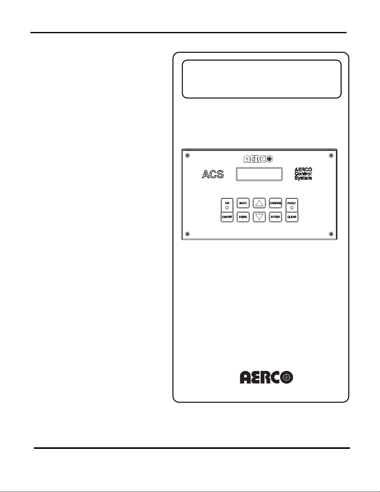
AERCO Control System
(ACS)
USER MANUAL
AERCO Control System (ACS) Front Panel
Revised: 04/23/2013
Used for up to Thirty-two (32)
• Benchmark Series Boilers
Installation, Operation, and Maintenance
AERCO Boilers including:
• AERCO Modulex Series Boilers
• AERCO KC-1000 Series Boilers
MC2: 04/23/13 Page 1 of 144
Page 2

GF-131
AERCO Control System (ACS)
AERCO International, Inc. • 100 Oritani Dr. • Blauvelt, New York 10913 • Phone: 800-526-0288
Installation, Operation, and Maintenance Manual
OMM-0081_0D
Technical Support:
1-800-526-0288
www.aerco.com
(Mon–Fri, 8am-5pm EST)
Disclaimer
The information contained in this manual is subject to change without notice from AERCO International,
Inc. AERCO makes no warranty of any kind with respect to this material, including but not limited to
implied warranties of merchantability and fitness for a particular application. AERCO International is not
liable for errors appearing in this manual. Nor for incidental or consequential damages occurring in
connection with the furnishing, performance, or use of this material.
MC2: 04/23/13 Page 2 of 144
Page 3

GF-131
AERCO Control System (ACS)
AERCO International, Inc. • 100 Oritani Dr. • Blauvelt, New York 10913 • Phone: 800-526-0288
Installation, Operation, and Maintenance Manual
OMM-0081_0D
Table of Contents
FOREWARD ................................................................................................................... 9
PHRASES, ABBREVIATIONS & ACRONYMS .......................................................... 9
1. ACS GENERAL INFORMATION ........................................................................... 11
1.1 SAFETY PRECAUTIONS AND WARNINGS .................................................. 11
1.2 INTRODUCTION .............................................................................................. 11
1.3 ACS GENERAL DESCRIPTION ...................................................................... 11
1.4 ACS FEATURES ............................................................................................. 12
1.4.1 Simplified Installation and Set-Up ........................................................... 12
1.4.2 User-Friendly Control System Interface ................................................. 12
1.4.3 Retention of Menu Option Settings ......................................................... 13
1.4.4 Application Flexibility .............................................................................. 13
1.4.5 Sequential or Parallel Operation ............................................................. 13
1.4.6 Accuracy ................................................................................................ 13
1.4.7 Bumpless Transfer ................................................................................. 13
1.4.8 Fault Alarm Surveillance ........................................................................ 13
1.4.9 ACS Programming Via RS232 Port. ....................................................... 13
2. ACS INSTALLATION ............................................................................................. 15
2.1 INTRODUCTION .............................................................................................. 15
2.2 SITE SELECTION AND MOUNTING .............................................................. 15
2.2.1 Mounting the ACS .................................................................................. 15
2.3 SITE SELECTION AND MOUNTING .............................................................. 16
2.4 POWER WIRING ............................................................................................. 17
2.5 SENSOR INSTALLATION AND WIRING ........................................................ 18
2.5.1 Header Sensor Installation ..................................................................... 19
2.5.2 Return Sensor Installation ...................................................................... 19
2.5.3 Outdoor Air Sensor Installation............................................................... 20
2.6 RS485 (MODBUS) WIRING AT THE ACS ...................................................... 22
2.6.1 ACS Bias Switches & Loop Termination Resistors ................................. 22
2.7 RS485 (MODBUS) WIRING, BIAS, AND TERMINATION AT AERCO
2.7.1 RS485 Wiring, Termination& Bias for Benchmark Series and KC1000 Boilers . 23
2.7.2 RS485 Wiring for Modulex Series Boilers .............................................. 29
2.8 SAMPLE RS485 (MODBUS) NETWORK DIAGRAMS ................................... 30
2.9 RS485 WIRING AT THE ACS ......................................................................... 31
BOILERS ................................................................................................................... 23
MC2: 04/23/13 Page 3 of 144
Page 4

GF-131
AERCO Control System (ACS)
AERCO International, Inc. • 100 Oritani Dr. • Blauvelt, New York 10913 • Phone: 800-526-0288
Installation, Operation, and Maintenance Manual
OMM-0081_0D
2.10 INTERLOCK WIRING ...................................................................................... 32
2.10.1 Interlock 1 (INT 1) Wiring ....................................................................... 32
2.10.2 Interlock 2 (INT 2) Wiring ....................................................................... 32
2.11 SETBACK WIRING ......................................................................................... 32
2.12 RELAY WIRING ............................................................................................... 32
2.12.1 System Start Relay ................................................................................. 33
2.12.2 Fault Alarm Relay ................................................................................... 33
2.12.3 Auxiliary Relay ........................................................................................ 33
2.13 4-20 MA WIRING ............................................................................................. 33
2.14 MOUNTING AND WIRING THE OPTIONAL ACS RELAY BOX ..................... 33
2.15 RELAY PANEL INSTALLATION AND WIRING .............................................. 34
2.16 RELAY PANEL COMPONENTS ..................................................................... 39
2.16.1 Power ..................................................................................................... 39
2.16.2 Inputs .................................................................................................... 39
2.16.3 Outputs .................................................................................................... 39
2.17 RELAY PANEL OPERATION .......................................................................... 40
2.18 ACS PROGRAMMING FOR USE WITH THE ACS RELAY PANEL ............... 41
2.18.1 RS485 Menu .......................................................................................... 41
2.18.2 Configuration Menu ................................................................................ 41
3. OPERATION .......................................................................................................... 43
3.1 INTRODUCTION .............................................................................................. 43
3.2 FRONT PANEL OPERATING CONTROLS AND DISPLAYS ......................... 43
3.3 ACS MENU STRUCTURE ............................................................................... 45
3.3.1 Menu Processing Procedure .................................................................. 45
3.4 OPERATING MENU ........................................................................................ 47
3.4.1 HEADER TEMP AND PERCENT OF LOAD .......................................... 47
3.4.2 HEADER SETPOINT ............................................................................. 47
3.4.3 OUTSIDE AIR TEMP ............................................................................. 47
3.4.4 I/O STATUS ........................................................................................... 48
3.4.5 RETURN TEMP ..................................................................................... 48
3.4.6 NETWORK BOILER OUTLET TEMPERATURE .................................... 48
3.4.7 NETWORK BOILER ERROR CODE ...................................................... 48
3.5 SETUP MENU .................................................................................................. 48
3.5.1 ENTER PASSWORD ............................................................................. 49
3.5.2 DATE AND TIME MENU OPTIONS ....................................................... 49
3.6 RS232 MENU ................................................................................................... 49
MC2: 04/23/13 Page 4 of 144
Page 5

GF-131
AERCO Control System (ACS)
AERCO International, Inc. • 100 Oritani Dr. • Blauvelt, New York 10913 • Phone: 800-526-0288
Installation, Operation, and Maintenance Manual
OMM-0081_0D
3.6.1 RS232 MODE......................................................................................... 49
3.6.2 RS232 BAUD RATE ............................................................................... 49
3.6.3 MODBUS ADDRESS ............................................................................. 49
3.6.4 NETWORK TIMEOUT ............................................................................ 50
3.6.5 MODBUS PASS THRU .......................................................................... 50
3.7 RS232 MENU ................................................................................................... 50
3.7.1 RS485 BAUD RATE ............................................................................... 50
3.7.2 MIN SLAVE ADDR ................................................................................. 50
3.7.3 MAX SLAVE ADDR ................................................................................ 50
3.7.4 NUMBER NETWK BLRS ....................................................................... 50
3.7.5 MODBUS CNTL TYPE ........................................................................... 50
3.7.6 NETW BOILER Xx ADDRESS=Yyy ....................................................... 51
3.8 FIELD ADJUST MENU .................................................................................... 51
3.8.1 HEADER SET MODE ............................................................................. 51
3.8.2 HDR HIGH LIMIT ................................................................................... 51
3.8.3 HDR LOW LIMIT .................................................................................... 51
3.8.4 INTERNAL SETPT ................................................................................. 51
3.8.5 RESET RATIO ....................................................................................... 51
3.8.6 BLDG REF TEMP .................................................................................. 52
3.8.7 REMOTE SIGNAL .................................................................................. 52
3.8.8 OFFSET ENABLE .................................................................................. 52
3.8.9 Offset Menu Options .............................................................................. 52
3.8.10 Setting Up an Offset Schedule ............................................................... 52
3.8.11 Setting Up a Manual Offset Schedule .................................................... 53
3.9 CONFIGURATION MENU ............................................................................... 53
3.9.1 BLR CNTL SELECT ............................................................................... 53
3.9.2 BOILER OP MODE ................................................................................ 53
3.9.3 PARALLEL MODE ................................................................................. 54
3.9.4 SEQUENTIAL......................................................................................... 54
3.9.5 SYS INTLK CONFIG .............................................................................. 54
3.9.6 BLR START LEVEL ............................................................................... 54
3.9.7 BLR STOP LEVEL ................................................................................. 54
3.9.8 MAX POWER INPUT ............................................................................. 55
3.9.9 FAIL SAFE MODE .................................................................................. 55
3.9.10 LEAD BLR SELECT (Lead Boiler Selection) .......................................... 55
3.9.11 LAST BLR SELECT (Last Boiler Selection) ........................................... 55
3.9.12 ROTATE TIME ....................................................................................... 55
3.9.13 RET SENSOR MODE (Return Sensor Mode) ........................................ 55
3.9.14 PLANT DT LIMIT (Plant Delta-Temperature Limit) ................................. 55
3.9.15 BOILER DELAY ..................................................................................... 56
MC2: 04/23/13 Page 5 of 144
Page 6

GF-131
AERCO Control System (ACS)
AERCO International, Inc. • 100 Oritani Dr. • Blauvelt, New York 10913 • Phone: 800-526-0288
Installation, Operation, and Maintenance Manual
OMM-0081_0D
3.9.16 DHW OPTION (Domestic Hot Water Option) ......................................... 56
3.9.17 NUMBER DHW BLRS (Number of Domestic Hot Water Boilers) ........... 56
3.9.18 DHW SIGNAL (Domestic Hot Water Signal) .......................................... 57
3.9.19 NUM DHW PRIORITY (Number of DHW Priority Boilers) ...................... 57
3.9.20 VALVE WAIT STATES ........................................................................... 57
3.9.21 SYS RELAY OPTION (System Relay Option) ........................................ 57
3.10 BOOST TEMP ................................................................................................. 57
3.10.1 RET TEMP BST DIS (RETURN TEMPERATURE BOOST DISABLE) . 57
3.10.2 BOOST MAX TIMER .............................................................................. 58
3.11 TUNING MENU ................................................................................................ 58
3.11.1 PROPORTIONAL BND .......................................................................... 58
3.11.2 INTEGRAL GAIN .................................................................................... 58
3.11.3 DERIVATIVE GAIN ................................................................................ 59
3.11.4 Decreasing Boiler Cycles ....................................................................... 59
3.11.5 HI_DB_SETPT_EN (High Deadband Setpoint Enable) .......................... 59
3.11.6 DEADBAND HIGH ................................................................................. 59
3.11.7 DEADBAND LOW .................................................................................. 59
3.11.8 SETPT DOWN RATE (Setpoint Down (descending) Rate ..................... 59
3.11.9 DEMAND OFFSET ................................................................................. 59
3.12 RELAY MENU ................................................................................................. 60
3.12.1 SYS START TEMP ................................................................................ 60
3.12.2 SYS START OPTION ............................................................................. 60
3.12.3 SYS START INTLK ................................................................................ 60
3.12.4 AUX RELAY OPEN ................................................................................ 60
3.12.5 AUX RELAY CLOSE .............................................................................. 60
3.12.6 FAULT ALRM RELAY ............................................................................ 60
3.12.7 FAULT ALARM BLRS ............................................................................ 61
3.12.8 FAULT ALRM CLEAR ............................................................................ 61
3.13 CALIBRATION MENU ..................................................................................... 61
3.13.1 HDR SENS OFFSET .............................................................................. 61
3.13.2 OUTD SENS OFFSET ........................................................................... 61
3.13.3 4 - 20 MA OFFSET ................................................................................. 61
3.13.4 RETN SENS OFFSET ............................................................................ 61
3.13.5 RAMP UP %/MIN ................................................................................... 61
3.13.6 RAMP DOWN %/MIN ............................................................................. 62
3.13.7 RESET DEFAULTS ................................................................................ 62
3.13.8 PASSTHRU WRITE ............................................................................... 62
3.13.9 VALVE WAIT TIME ................................................................................ 62
3.13.10 SYSTEM OVERRIDE (Modbus Enable/Disable) .................................... 62
MC2: 04/23/13 Page 6 of 144
Page 7

GF-131
AERCO Control System (ACS)
AERCO International, Inc. • 100 Oritani Dr. • Blauvelt, New York 10913 • Phone: 800-526-0288
Installation, Operation, and Maintenance Manual
OMM-0081_0D
3.14 ACS QUICK-START GUIDE MENU ................................................................ 63
3.14.1 CONSTANT SETPT MODE (Default): .................................................... 64
3.14.2 REMOTE SETPT MODE: ....................................................................... 65
3.14.3 OUTDOOR RESET MODE .................................................................... 66
4. PROGRAMMING ACS OPERATING MODES ....................................................... 67
4.1 INTRODUCTION .............................................................................................. 67
4.2 OUTDOOR RESET MODE .............................................................................. 67
4.2.1 Selecting Outdoor Reset Mode .............................................................. 68
4.2.2 Determining Reset Schedule .................................................................. 68
4.2.3 Entering Reset Ratio and Building Reference Temperature ................... 69
4.2.4 SELECTING BOILER OPERATING MODE ........................................... 69
4.2.5 Entering System Start Temperature ....................................................... 70
4.2.6 Entering Boiler Start and Boiler Stop Levels .......................................... 70
4.3 REMOTE SETPOINT MODE ........................................................................... 71
4.3.1 Selecting Remote Setpoint Mode ........................................................... 71
4.3.2 Entering Header High Limit and Low Limit Temperatures ...................... 72
4.3.3 Selecting Remote Signal Type ............................................................... 73
4.3.4 Selecting Boiler Operating Mode ............................................................ 73
4.3.5 Entering Boiler Start & Stop Levels ........................................................ 74
4.4 CONSTANT SETPOINT MODE ....................................................................... 74
4.4.1 Selecting Constant Setpoint Mode ......................................................... 75
4.4.2 Selecting Internal Setpoint Temperature ................................................ 75
4.4.3 Selecting Boiler Operating Mode ............................................................ 76
4.4.4 Entering Boiler Start and Boiler Stop Levels .......................................... 76
4.5 “Temp and Load” Option............................................................................... 76
4.6 “Start Enabled” Option .................................................................................. 77
4.7 System Initialization and Polling .................................................................. 77
4.8 Testing the System ........................................................................................ 78
5. TROUBLESHOOTING ........................................................................................... 81
5.1 Fault Messages And Common Problems ..................................................... 81
APPENDIX A: ACS MENUS ...................................................................................... 85
APPENDIX B: STATUS AND FAULT MESSAGES ..................................................... 91
B.1 C-MORE STATUS AND FAULT MESSAGES .................................................. 91
B.3 Deciphering the “FAULT Code” Reading from the BCM (used in Modulex
MC2: 04/23/13 Page 7 of 144
B.2 CONVERSION EQUATIONS FOR TEMPERATURE VARIABLES .................. 96
Boilers) ..................................................................................................................... 97
B.4 BCM (BOILER COMMUNICATION MODULE) FAULT CODES ....................... 98
Page 8

GF-131
AERCO Control System (ACS)
AERCO International, Inc. • 100 Oritani Dr. • Blauvelt, New York 10913 • Phone: 800-526-0288
Installation, Operation, and Maintenance Manual
OMM-0081_0D
APPENDIX C: RESET SCHEDULE AND OUTDOOR RESET RATIO CHARTS ..... 105
B.5 BCM (BURNER MANAGEMENT MODULE) FAULT CODES .......................... 99
B.6 ACS (AERCO CONTROL SYSTEM) I/O STATUS .......................................... 102
C.1 USING THE CHARTS TO DETERMINE RESET SCHEDULE ........................ 105
APPENDIX D: NTC TEMPERATURE SENSOR RESISTANCE ............................... 111
APPENDIX E: ACS WIRING DIAGRAM ................................................................... 113
APPENDIX F: ACS PARTS AND ACCESSORIES ................................................... 115
APPENDIX G: PROGRAMMING USING RS232 COMMUNICATION ....................... 117
G.1 INTRODUCTION ............................................................................................. 117
G.2.1 Logging on to a Remote Machine Using PuTTY .................................... 117
G.2.2 Running a Command on a Remote Machine Using PuTTY ................... 118
G.3 RS232 COMMUNICATION SET-UP ................................................................ 119
APPENDIX H: ACS MODBUS ADDRESS ASSIGNMENTS .................................................. 127
H.1 ACS CONTROLLER STANDARD INPUT REGISTER ASSIGNMENTS ........ 127
APPENDIX I: BOILER START AND STOP LEVELS ............................................... 143
C.2 DETERMINING RESET SCHEDULE BY FORMULA ...................................... 105
G.2 AQUIRING THE PuTTY APPLICATION .......................................................... 117
G.4 PROGRAMMING PROCEDURE ..................................................................... 119
H.2 ACS CONTROLLER STANDARD HOLDING REGISTER ASSIGNMENTS ... 134
MC2: 04/23/13 Page 8 of 144
Page 9

GF-131
AERCO Control System (ACS)
Installation, Operation, and Maintenance Manual
OMM-0081_0D
AERCO International, Inc. • 100 Oritani Dr. • Blauvelt, New York 10913 • Phone: 800-526-0288
Phrase, Abbreviation or
A (Amp)
Ampere
ACS
AERCO Control System
ADDR
Address
ALRM
Alarm
AUX
Auxiliary
Building Automation System, often used interchangeably with EMS (see
below)
Symbol rate, or simply the number of distinct symbol changes (signaling
each symbol is 1 bit long.
BCM
Boiler Control Module used with AERCO Modulex Series Boilers
BLR
Boiler
BND
Band
A pair of resistors used to force the communication line to a definite logic
state so that noise is not picked up as invalid data during communication.
BLDG (Bldg)
Building
C-More Controller
(or Control Box)
A control system developed by AERCO and currently used in all
Benchmark and KC1000 Series product lines.
CNTL
Control
DHW
Domestic Hot Water
DYN
Dynamic
EMS
Energy Management System; often used interchangeably with BAS
Ethernet
A computer networking technology for Local Area Networks (LANs)
FOREWARD
The AERCO Control System (ACS) is AERCO’s solution for a flexible boiler plant controller. The
system can control a boiler plant comprised of AERCO Benchmark Series, Modulex Series or
KC1000 Boilers. The ACS can stage and coordinate the operation of up to thirty-two (32)
AERCO Boilers with maximized efficiency. With individual boilers with turn-down ratios as high
as 20:1, a 5-boiler plant can deliver a system turn-down ratio of 100:1 when the boilers are
staged to operate sequentially.
The ACS can also be used in a combination boiler plant to both supply building heat and also
heat water for domestic applications. There are multiple options built in to do this. Some of
these options require a mated AERCO Relay Box to be installed along with the ACS in order to
effectively and safely control the supporting hydronic valves and their interaction with the
boilers.
The ACS is fully compatible with a wide array of Building Automation Systems (BAS) or Energy
Management Systems (EMS) utilizing Modbus Protocol. The BAS or EMS communicates with
the ACS utilizing a RS232 interface. If the BAS or EMS uses a RS485 port, the ACS can be
ordered with a RS485-to-RS232 Converter which can be easily installed within the ACS wiring
compartment.
PHRASES, ABBREVIATIONS & ACRONYMS
The phrases, abbreviations and acronyms used in this document are listed in the following
table:
Phrases, Abbreviations and Acronyms
Acronym
BAS
Baud Rate
Bias Resistors
events) transmitted per second. It is not equal to bits per second, unless
Meaning
MC2: 04/23/13 Page 9 of 144
Page 10

GF-131
AERCO Control System (ACS)
AERCO International, Inc. • 100 Oritani Dr. • Blauvelt, New York 10913 • Phone: 800-526-0288
Installation, Operation, and Maintenance Manual
OMM-0081_0D
Phrase, Abbreviation
FDX
Full-Duplex
FLT
Fault
GND
Ground
HDR
Header
HDX
Half-Duplex
Hex
Hexadecimal Number (0 - 9, A - F)
Hz
Hertz (Cycles Per Second)
INTLK
Interlock
I/O
Input/Output
Input/Output (I/O) Box currently used on all Benchmark and KC Series
products
IP
Internet Protocol
ISO
Isolated
LSB
Least Significant Byte
LSD
Least Significant Digit
MA (mA)
Milliampere
MAX (Max)
Maximum
MIN (Min)
Minimum
A serial, half-duplex data transmission protocol developed by AEG
Modicon
MSB
Most Significant Byte
MSD
Most Significant Digit
MS/TP
Master-Slave/Token-Passing (usually over RS485 networks)
OFFS
Offset
OUTD
Outdoor
PTP
Point-to-Point (usually over RS232 networks)
REF (Ref)
Reference
Response Time
The maximum amount of time allowed to receive a response to a request
RS232
(or EIA-232)
A standard for serial, full-duplex (FDX) transmission of data based on the
RS232 Standard
RS422
(or EIA-422)
A standard for serial, full-duplex (FDX) transmission of data based on the
RS422 Standard
RS485
(or EIA-485)
A standard for serial, half-duplex (HDX) transmission of data based on
the RS485 Standard
RTN
Return
RTU
Remote Terminal Unit
SEN
Sensor
SETPT (Setpt)
Setpoint Temperature
SHLD (Shld)
Shield
SLTA
Serial LonTalk Adapter
SYS
System
TEMP (Temp)
Temperature
A resistor placed at each end of a daisy-chain or multi-drop network in
communication
VAC
Volts, Alternating Current
VDC
Volts, Direct Current
VFD
Vacuum Fluorescent Display
Phrases, Abbreviations and Acronyms (Continued)
or Acronym
I/O Box
Modbus®
Meaning
Terminating Resistor
MC2: 04/23/13 Page 10 of 144
order to prevent reflections that may cause invalid data in the
Page 11

GF-131
AERCO Control System (ACS)
Installation, Operation, and Maintenance Manual
OMM-0081_0D
AERCO International, Inc. • 100 Oritani Dr. • Blauvelt, New York 10913 • Phone: 800-526-0288
Dimensions
Weight
Power Requirements
1. ACS GENERAL INFORMATION
1.1 SAFETY PRECAUTIONS AND WARNINGS
The warnings and cautions appearing throughout this manual should be reviewed and
thoroughly understood prior to attempting to install, operate, troubleshoot or repair the ACS
Controller.
1.2 INTRODUCTION
This manual provides installation, operation and troubleshooting instructions for the AERCO
Control System, Model 5R5-384.
1.3 ACS GENERAL DESCRIPTION
The ACS (Figure 1-1) is a rugged, flexible controller designed to stage and coordinate the
operation of up to 32 AERCO Benchmark Series, Modulex Series or KC1000 Boilers while
maximizing operational efficiency. Under normal load conditions, the ACS can precisely regulate
the header temperature of the boiler plant within ±2°F.
Boiler plant control is accomplished via a RS485 network utilizing Modbus protocol. For facilities
that have taken a building-wide approach to energy efficiency, the ACS can be easily integrated
with an Energy Management System (EMS) or Building Automation System (BAS) utilizing
Modbus protocol. Physical connection to the remote EMS or BAS is accomplished via an RS232
interface. EMS/BAS integration will also permit utilization of the pass-thru function incorporated
in the ACS. The pass-thru function permits the remote system to monitor up to 35 operating
parameters from each boiler in the plant.
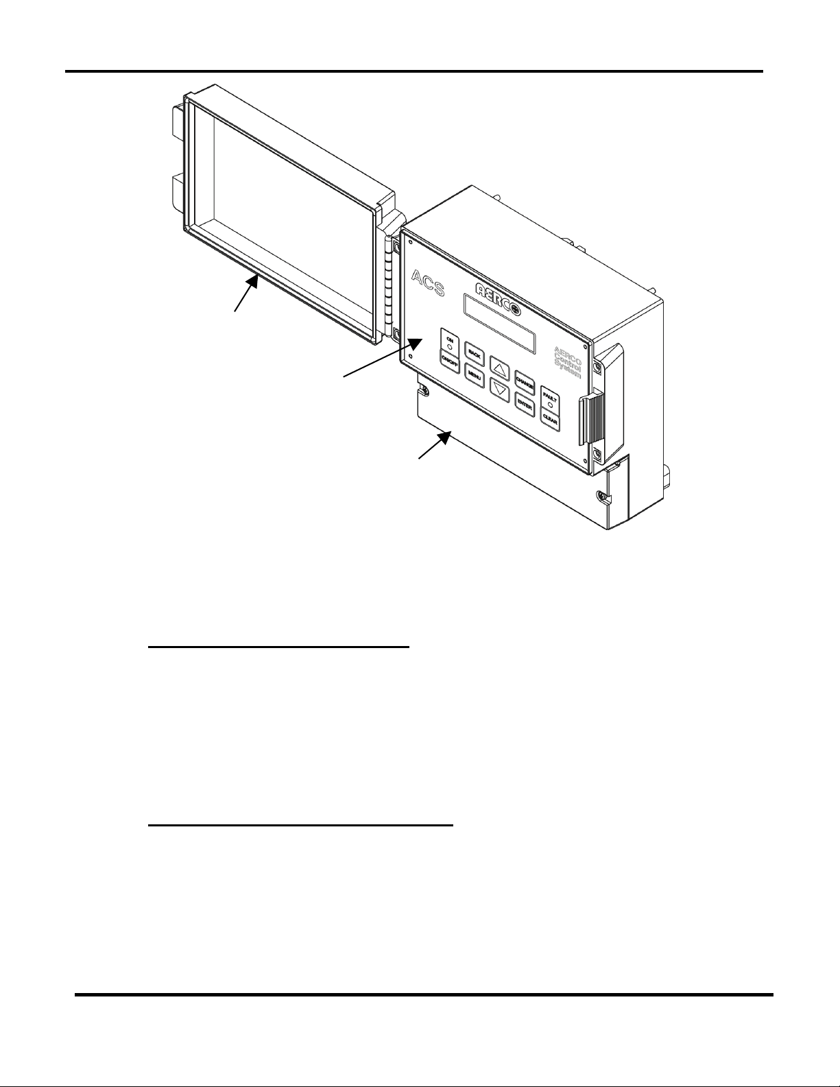
The ACS is housed in a NEMA 13 enclosure. A hinged clear-plastic cover over the unit’s panel
controls protects against incidental contact of control settings and provides a degree of
protection against airborne debris and the spraying or splashing of water. The physical
dimensions, weight and electrical power requirements for the ACS are as follows:
Each ACS shipment includes a Header Sensor Kit, Part No. GM-122790 which is required for all
modes of operation. Other available options which can be ordered with your shipment include:
• Outdoor Air Sensor Kit, Part No. GM-122781: Required for Outdoor Reset Mode
Operation
9.50” W x 7.25” H x 4.00” D
3 lbs.
85-to-265 VAC, Single-Phase, 50-60 Hz @ 1A
• Return Sensor Kit, Part No. 122790 (Same as Header Sensor Kit): Used for external
monitoring of boiler water return temperature
• RS485-to-RS232 Converter, Part No 124943: For use with EMS or BAS equipment that
has a RS485 Port
MC2: 04/23/13 Page 11 of 144
Page 12
GF-131
AERCO Control System (ACS)
AERCO International, Inc. • 100 Oritani Dr. • Blauvelt, New York 10913 • Phone: 800-526-0288
Installation, Operation, and Maintenance Manual
OMM-0081_0D
Cover
Clear Plastic
Front Panel
Wiring Compartment Cover
Figure 1-1: AERCO Control System (ACS)
1.4 ACS FEATURES
The following paragraphs briefly describe some of the unique features incorporated in the ACS.
1.4.1 Simplified Installation and Set-Up
The ACS system operates on single-phase input power ranging from 85 to 265 VAC, 50-60 Hz.
Connections to the boiler plant are accomplished utilizing a 2-wire RS485 network connected in
a daisy-chain configuration. When an EMS or BAS is used with the ACS, connections are made
via the RS232 port terminals. In the event that the EMS or BAS is not equipped with a RS232
port, the ACS can be ordered with a RS485 to RS232 Converter which can be easily installed
within the wiring compartment of the ACS. With the exception of AC power, interlock and
setback inputs and relay outputs, ACS connections are accomplished using shielded-twisted
pair cable.
1.4.2 User-Friendly Control System Interface
The unit incorporates a menu-driven architecture which is comprised of 9 primary menus. The
user interface to these menus is accomplished via the ACS control panel and a Vacuum
Fluorescent Display (VFD). The display is capable of displaying two lines with 16 characters per
line. Virtually all of the control panel keys are identical to the C-More Control System currently
used on AERCO Benchmark Series and KC1000 Boilers. This commonality will help simplify the
time required for system setup of the ACS.
MC2: 04/23/13 Page 12 of 144
Page 13

GF-131
AERCO Control System (ACS)
AERCO International, Inc. • 100 Oritani Dr. • Blauvelt, New York 10913 • Phone: 800-526-0288
Installation, Operation, and Maintenance Manual
OMM-0081_0D
1.4.3 Retention of Menu Option Settings
By using non-volatile memory, the ACS retains program and menu settings during shut-down or
when input AC power is interrupted. Settings can be retained for more than 2 years.
1.4.4 Application Flexibility
Four different configuration options can be selected to match the needs of any closed-loop
system. These configurations are: Outdoor Reset, Constant Setpoint, Remote Setpoint via a 420 Ma input and Remote Setpoint via Modbus.
Three different domestic hot water (DHW) options are selectable for controlling the combination
boilers and valves that are being used to provide heated domestic water.
1.4.5 Sequential or Parallel Operation
Boilers can be programmed for either sequential or parallel operation using the ACS keypad
controls. When set for sequential operation, the boilers are brought on-line one at a time as
needed. When set for parallel operation, the boilers are all brought on-line together at the same
firing rate.
1.4.6 Accuracy
Using PID (Proportional Integral Derivative) and Ramp-Up/Ramp-Down Modulation Control
Algorithms, the ACS provides dynamic responses to all changes in boiler plant operation.
Header temperatures, as well as percentages of boiler input are precisely controlled with
virtually no over-shoot or short-cycling of boiler units. A header temperature accuracy of ±2°F is
virtually assured during continuous plant operation.
1.4.7 Bumpless Transfer
When operated sequentially, The ACS stages boilers on and off at selectable firing rate
percentages. The result is a seamless transition with undetectable room temperature changes.
In addition, when in sequential mode, the ACS sequences boilers using a first-on, first-off basis,
thereby equalizing the accumulated run time of all boilers in the plant.
The ACS also continuously monitors the number of Boilers that are available for operation. In
the event of a boiler malfunction, or required servicing, the ACS automatically compensates for
a lack of response from any unit and brings on the next available boiler to satisfy the demand.
This feature operates in both sequential and parallel modes.
1.4.8 Fault Alarm Surveillance
If an EMS or BAS is not used with the ACS to monitor faults, a Fault Alarm Relay can be
activated thereby notifying facility managers of faults associated with the ACS.
1.4.9 ACS Programming Via RS232 Port.
If desired, the ACS can be programmed by connecting a Laptop Computer or other terminal
emulation device to the RS232 Port terminals on the ACS. Detailed set-up instructions and
available command listings are provided in Appendix G. Most settings are also programmable
using Modbus.
MC2: 04/23/13 Page 13 of 144
Page 14

GF-131
AERCO Control System (ACS)
AERCO International, Inc. • 100 Oritani Dr. • Blauvelt, New York 10913 • Phone: 800-526-0288
Installation, Operation, and Maintenance Manual
OMM-0081_0D
(This page intentionally blank)
MC2: 04/23/13 Page 14 of 144
Page 15

GF-131
AERCO Control System (ACS)
Installation, Operation, and Maintenance Manual
OMM-0081_0D
AERCO International, Inc. • 100 Oritani Dr. • Blauvelt, New York 10913 • Phone: 800-526-0288
2. ACS INSTALLATION
2.1 INTRODUCTION
This Chapter provides the descriptions and procedures necessary to mount the ACS and
connect all boiler plant units and applicable sensors. Guidelines are also provided for
connection of an EMS or BAS being used with the system. Refer to the wiring diagram provided
in Appendix E when making all wiring connections to the ACS.
2.2 SITE SELECTION AND MOUNTING
Ensure that the site selected for installation of the ACS provides the following:
Access to single-phase AC power from 110 to 240 VAC, 60 Hz nominal
Sufficient clearances to permit maintenance and setup/operational tasks on the ACS.
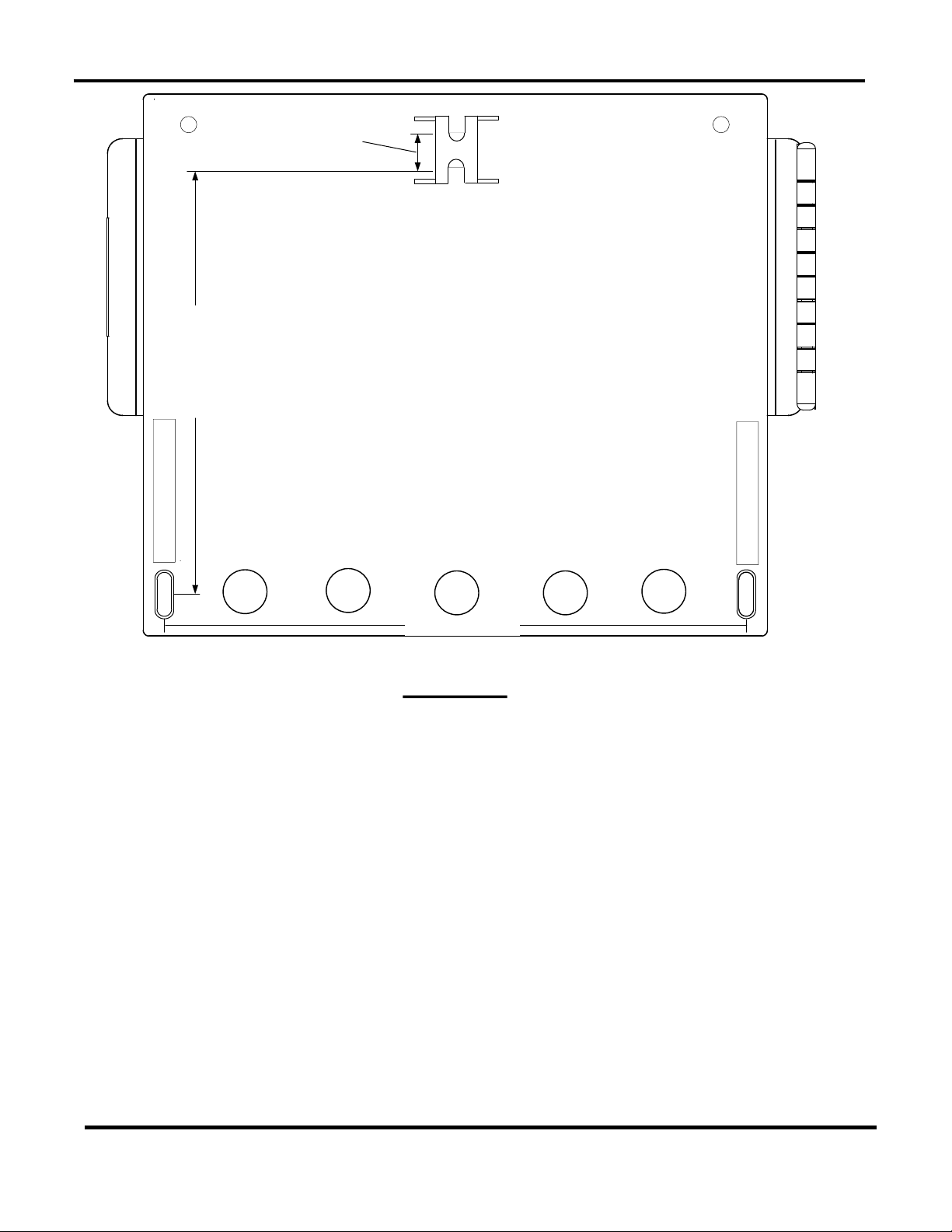
2.2.1 Mounting the ACS
AERCO recommends that the ACS be wall-mounted using a sheet of plywood or other suitable
material. For easy viewing, the ACS controls and display should be at eye level. Mounting is
accomplished using three screws (not provided). The spacing for the three screws are indicated
on the rear of the ACS in millimeters. Figure 2-1 shows the rear of the panel enclosure and also
indicates the required spacing for the three mounting screws in inches. Proceed as shown
below, to mount the unit:
Mounting the ACS Controller
1. First install a screw on the mounting surface at the top center location shown in
Figure 2-1. Leave a space of approximately 1/8 inch between the mounting surface
and the head of the screw.
2. Remove the wiring compartment cover from the front of the ACS (see Figure 1-1) to
provide access to the slots for the two lower mounting screw locations.
3. Hang the ACS on the installed top screw. Position the unit so it is level.
4. Mark the locations for the two lower screws.
5. Remove the ACS and drill two pilot holes for the lower screws.
6. Replace the ACS on the installed top-center screw.
7. Secure the ACS to the wall by installing the two lower screws. DO NOT over-tighten
the screws.
MC2: 04/23/13 Page 15 of 144
Page 16
GF-131
AERCO Control System (ACS)
AERCO International, Inc. • 100 Oritani Dr. • Blauvelt, New York 10913 • Phone: 800-526-0288
Installation, Operation, and Maintenance Manual
OMM-0081_0D
198 mm (7.8")
145 mm (5.7")
15 mm
(0.6")
REAR VIEW
Figure 2-1: ACS Mounting Provisions
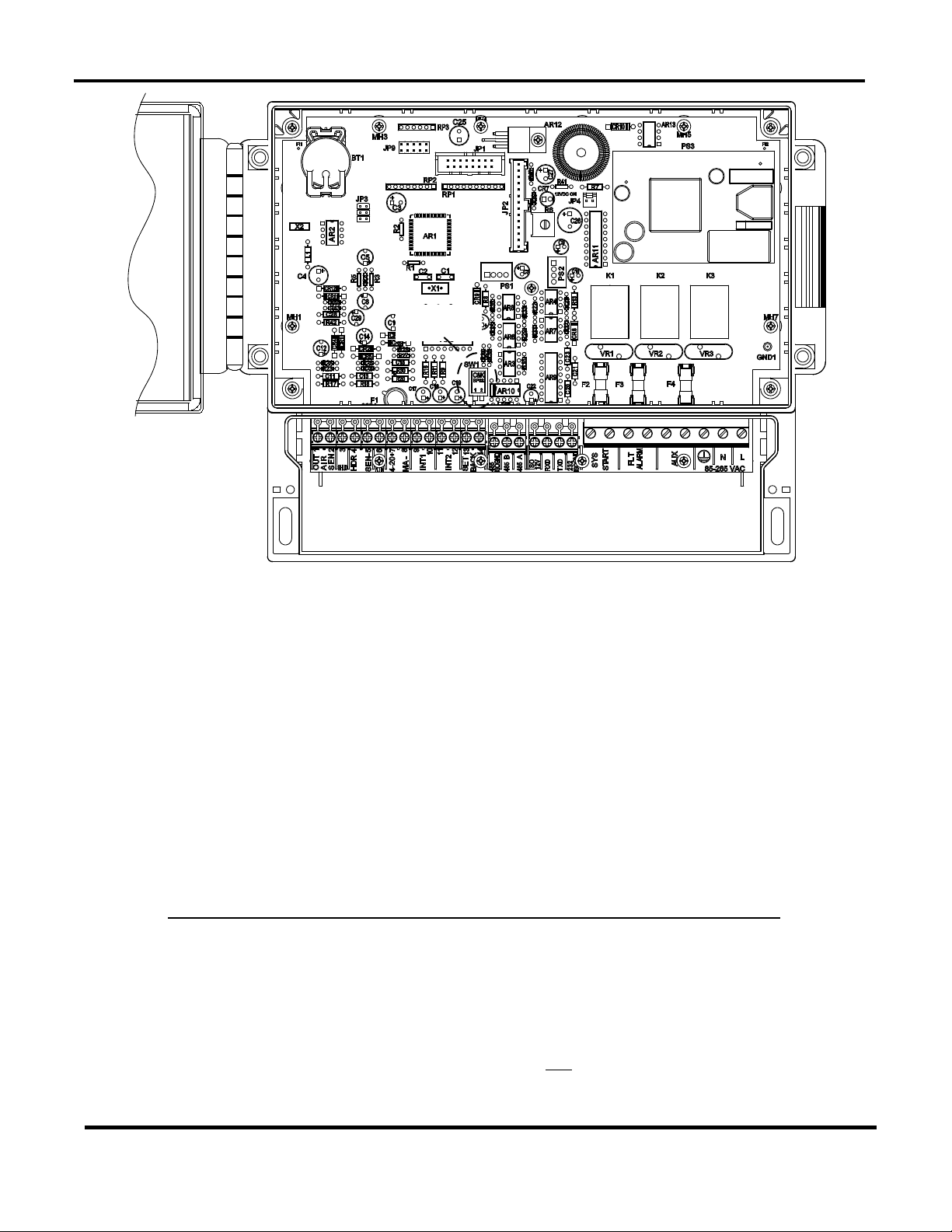
2.3 SITE SELECTION AND MOUNTING
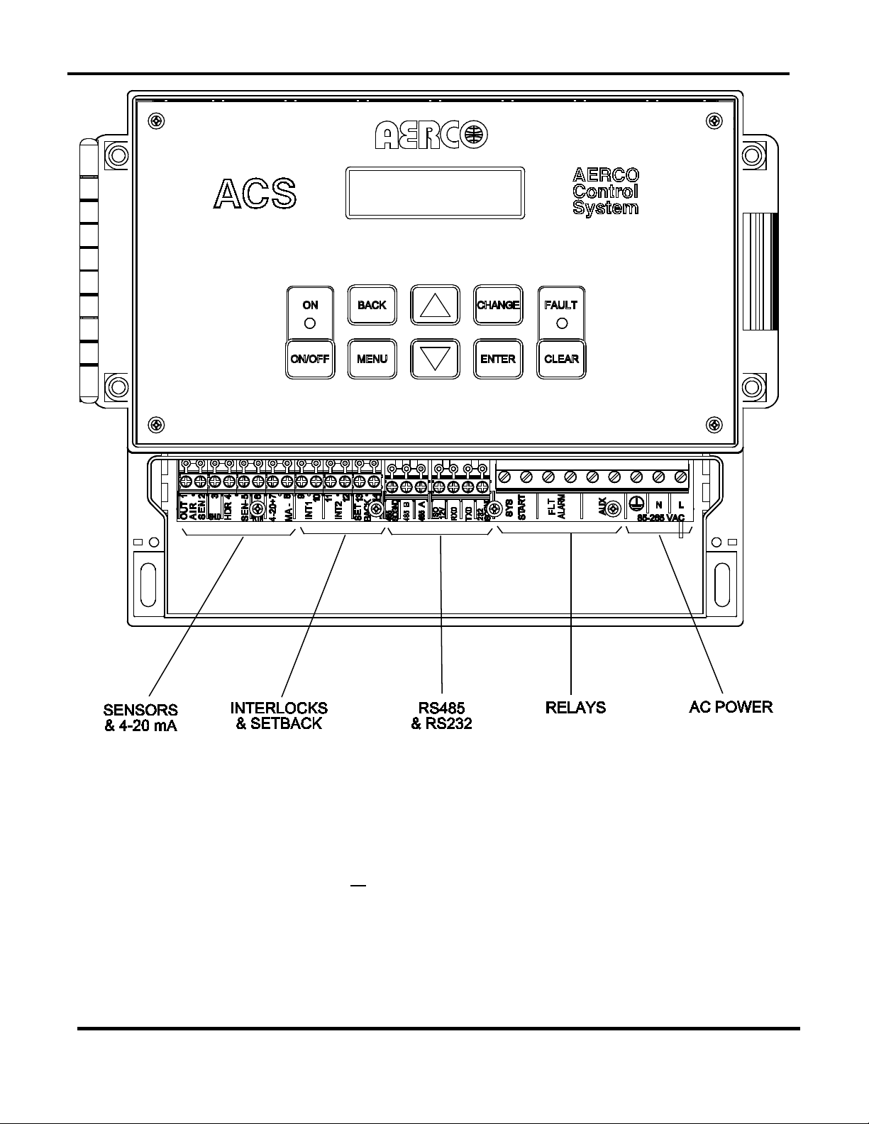
All wiring connections to the ACS are made at the terminals located behind the wiring
compartment cover as shown in Figure 2-2. Run all wiring through the knock-outs provided on
the bottom surface of the unit. Shielded, twisted-pair cable should be used for sensor and
communication wiring. This wiring should be 18 to 24 AWG. Examples of suitable sensor and
communication wire are: Belden 9841, 8761, 3105A or equivalent. AC power wiring should be
14 to 18 AWG. The ACS wiring diagram is provided in Appendix E. Once mounting is complete
and the ACS is secured in place, loosen the two captive screws on the wiring compartment
cover using a Phillips screwdriver. Feed all wiring through the knock-outs provided on the
bottom of the panel.
NOTE
Refer to the wiring diagram provided in Appendix E when making all wiring
connections to the ACS.
MC2: 04/23/13 Page 16 of 144
Page 17

GF-131
AERCO Control System (ACS)
AERCO International, Inc. • 100 Oritani Dr. • Blauvelt, New York 10913 • Phone: 800-526-0288
Installation, Operation, and Maintenance Manual
OMM-0081_0D
Wiring ACS Power Connections
DO NOT apply power to the ACS until all of the required external connections
THE ACS CAN BE POWERED BY SINGLE-PHASE AC VOLTAGES
RANGING FROM 85 TO 265 VAC. THEREFORE, EXERCISE
EXTREME CARE WHEN CONNECTING POWER WIRING TO THE
UNIT. ENSURE THAT THE EXTERNAL CIRCUIT BREAKER
SUPPLYING LINE VOLTAGE TO THE ACS IS TURNED OFF TO
AVOID SEVERE ELECTRICAL SHOCK.
2.4 POWER WIRING
Use 14 to 18 AWG wire for AC power connections and proceed as shown below:
1. Feed the power wiring through the right-most knock-out in the bottom of the panel
enclosure (Figure 2-2).
2. Connect the Line (black), Neutral (white) and Ground (green) wire leads to the L, N
and (GND) terminals. The terminal blocks can be detached from the ACS headers
if necessary to simplify field wiring connections.
3. Following completion of power wiring, turn on the external circuit breaker or switch and
apply power to the unit. The ACS display will momentarily show:
AERCO ACS
REV X.XX
(Where: X.XX represents the revision level of the installed ACS software)
4. Next, since the Header Sensor is not yet installed, the display will then show:
HEADER TEMP
SENSOR ERROR
The red FAULT LED indicator will also light and a fault message will alternately be
displayed as follows:
HEADER SENSOR
ERROR
5. Press the ON-OFF key on the keypad. The green ON LED indicator will light and the
ACS display will continue to show the above message.
6. After verifying proper power connections, press the ON-OFF key. The ON LED will turn
off.
7. Turn off the external power switch and/or circuit breaker. The ACS display will go
blank.
8.
described in paragraphs 2.5 through 2.11 have been completed.
MC2: 04/23/13 Page 17 of 144
Page 18
GF-131
AERCO Control System (ACS)
AERCO International, Inc. • 100 Oritani Dr. • Blauvelt, New York 10913 • Phone: 800-526-0288
Installation, Operation, and Maintenance Manual
OMM-0081_0D
Figure 2-2: ACS with Wiring Compartment Cover Removed
2.5 SENSOR INSTALLATION AND WIRING
Two types of sensors may be installed, including a Header Sensor and an Outside Air Sensor.
The Header Sensor is required for all modes of operation. The Outdoor Air Sensor is required
for operation in the Outdoor Reset Mode. All Sensor wiring should be run separately from power
wiring to avoid inducing electrical noise on the sensor wiring.
If desired, an optional Return Sensor may also be installed, which is the same type and part
number as the Header Sensor, however it is only used for Plant DT limit operation and for
monitoring purposes.
MC2: 04/23/13 Page 18 of 144
Page 19

GF-131
AERCO Control System (ACS)
AERCO International, Inc. • 100 Oritani Dr. • Blauvelt, New York 10913 • Phone: 800-526-0288
Installation, Operation, and Maintenance Manual
OMM-0081_0D
Header Sensor Installation
Return Sensor Installation
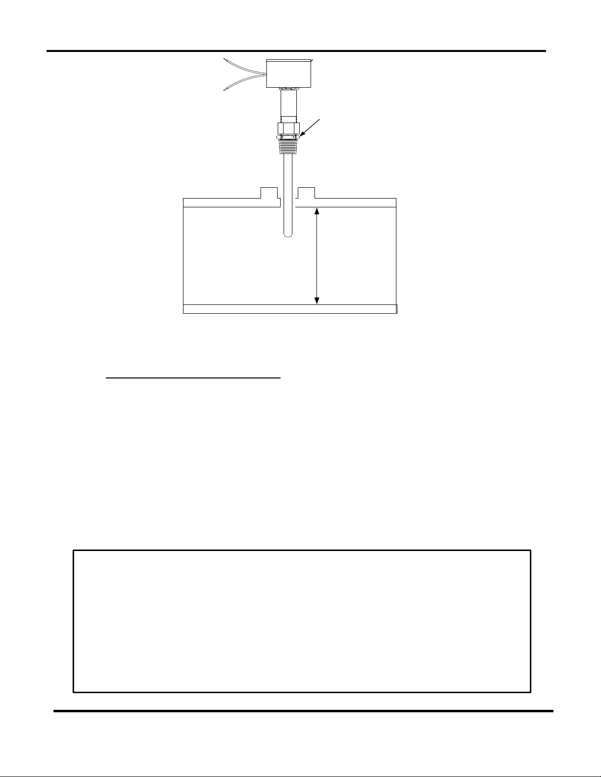
2.5.1 Header Sensor Installation
A Header Sensor Kit, (part no. 122790) is provided with the ACS. This Kit contains the Header
Sensor (64038), a Thermowell (122758) and some heat conductive grease which MUST be
used with the Sensor. When installing the Sensor, use a 1/2 inch NPT tapped coupling or a 4 x
4 x 1/2 inch Tee fitting. Shielded pair, 18 AWG cable (Belden # 8760 or equiv.) is recommended
for Header Sensor wiring. The Header Sensor must be installed between 2 and 10 feet
downstream of the LAST boiler in the boiler plant’s supply water header. Install the Header
Sensor as shown below:
NOTE
The Header Sensor is a thermistor type sensor. The Resistance vs.
Temperature Chart for this sensor is provided in Appendix D. Length of
Header Sensor wire leads should not exceed 600 feet.
1. Refer to Figure 2-3 for the Header Sensor installation details.
2. Install the Header Sensor and Thermowell into the 1/2 inch NPT tapped coupling or a 4 x
4 x 1/2 inch Tee fitting using heat-conductive grease provided. This will aid in its
response.
3. For proper response, ensure that the Header Sensor probe is inserted at least 2 inches
into the water flow.
4. Using shielded pair cable (Belden #8760 or equiv.) connect the Header Sensor leads to
HDR SEN terminals 4 and 5 on the ACS. There is no polarity to observe when making
these connections.
5. Terminate the cable shield at SHLD terminal 3 of the ACS. DO NOT terminate the shield
at the Sensor end of the cable.
2.5.2 Return Sensor Installation
The Return Sensor is required to activate the Plant Delta Temperature function, as described in
section 3.9.14, on page 54.
As mentioned in paragraph 2.5, the Return Sensor is identical to the Header Sensor.
Therefore, if a Return Sensor is being installed, another Header Sensor Kit (part no. 122790) is
required. The Return Sensor should be installed in the boiler water return line within 3 feet of the
first boiler in the boiler plant’s return water line. The installation details shown in Figure 2-3 for
the Header Sensor also apply to the Return Sensor. If used, install the Return Sensor as shown
below:
1. Refer to Figure 2-3 and install the Return Sensor and Thermowell into the 1/2 inch
tapped coupling or or Tee fitting using heat conductive grease.
2. Using shielded pair cable (Belden #8760 or equiv.), connect Return Sensor leads to
terminals 6 and 5 on the ACS. There is no polarity to observe when making these
connections.
3. Terminate the cable shield at SHLD terminal 3 of the ACS. DO NOT terminate the
shield at the Sensor end of the cable.
MC2: 04/23/13 Page 19 of 144
Page 20
GF-131
AERCO Control System (ACS)
AERCO International, Inc. • 100 Oritani Dr. • Blauvelt, New York 10913 • Phone: 800-526-0288
Installation, Operation, and Maintenance Manual
OMM-0081_0D
PROBE DEPTH MUST
EXTEND AT LEAST 2"
INTO PIPE
WELDED 1/2"
COUPLING OR
4"x4*x1/2"
T - FITTING
HEADER SENSOR
WITH THERMOWELL
INSTALLED
Outdoor Air Sensor Installation
Figure 2-3: Header Sensor Installation Details
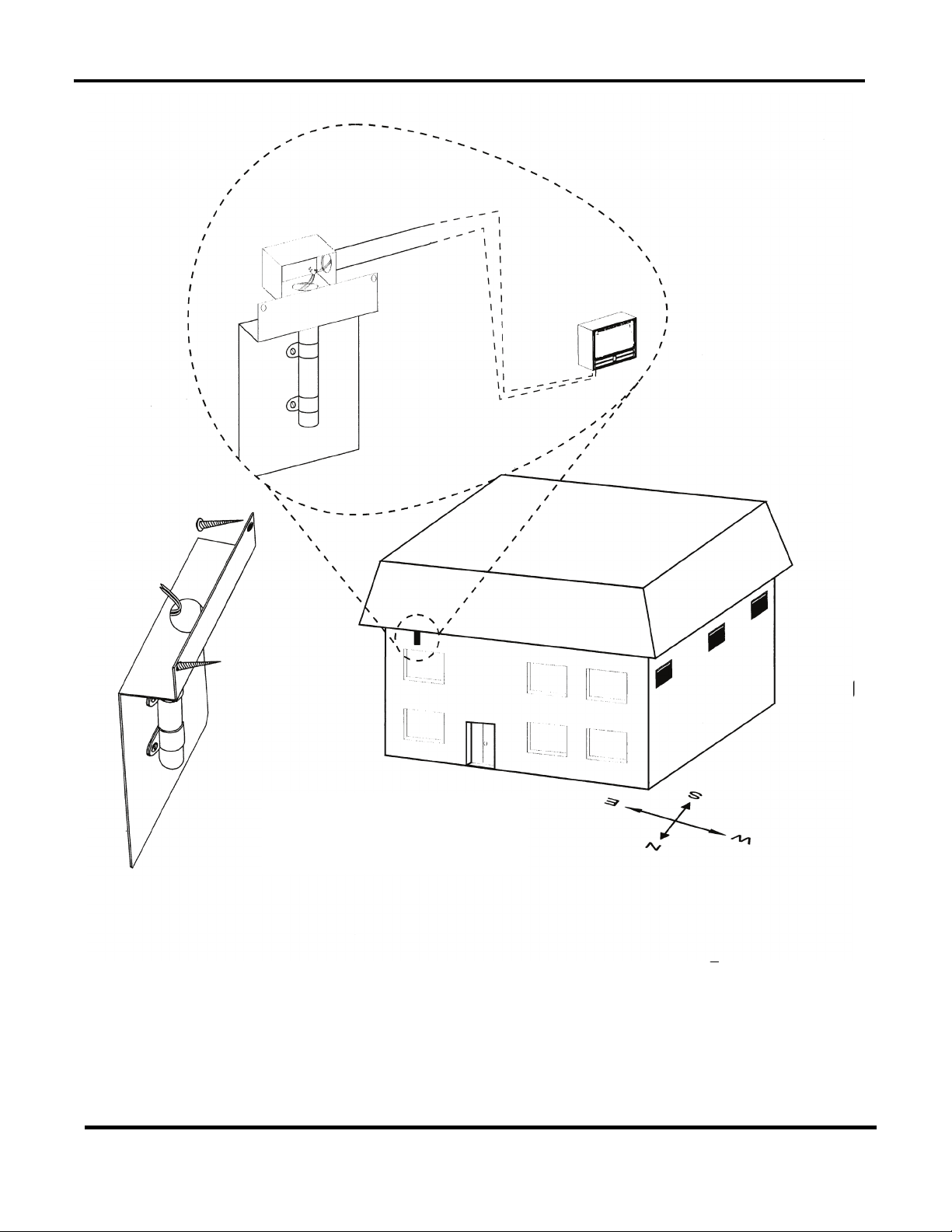
2.5.3 Outdoor Air Sensor Installation
The Outdoor Air Temperature Sensor (part no. GP-122662) is required when operating in the
ACS in the Outdoor Reset Mode (paragraph 4.2). An Outdoor Air Sensor Kit (part no. GM-
122781) is also available. This kit contains the Sensor (GP-122662) and a Mounting Bracket for
wall mounting. The Outdoor Air Sensor should be mounted on the North side of the building,
shielded from direct sunlight, and away from air intakes or outlets from the building. Shielded
pair 18 AWG cable (Belden # 8760 or equiv.) is recommended for sensor wiring. The Outdoor
Air Sensor can be mounted up to 600 feet from the ACS. See instructions below.
NOTE
The Outdoor Air Sensor is a thermistor type sensor. The Resistance vs.
Temperature Chart for this sensor is provided in Appendix E. Length of
Header Sensor wire leads should not exceed 600 feet.
1. Refer to Figure 2-4 for a typical Outdoor Air Sensor installation.
2. Attach the sensor to the mounting bracket and secure the bracket in a suitable location
on the North side of the building.
3. Using shielded pair cable (Belden #8760 or equiv.), connect the two Sensor leads to
terminals 1 and 2 on the ACS. There is no polarity to observe when connecting the
sensor.
4. Terminate the cable shield at SHLD terminal 3 of the ACS. DO NOT terminate the shield
at the Sensor end of the cable.
MC2: 04/23/13 Page 20 of 144
Page 21
GF-131
AERCO Control System (ACS)
AERCO International, Inc. • 100 Oritani Dr. • Blauvelt, New York 10913 • Phone: 800-526-0288
Installation, Operation, and Maintenance Manual
OMM-0081_0D
INSTALL SENSOR ON NORTH
FACING WALL OUT OF DIRECT
SUNLIGHT AND AWAY FROM
ALL AIR INLETS/OUTLETS
Figure 2-4: Outdoor Air Sensor Installation
MC2: 04/23/13 Page 21 of 144
Page 22

GF-131
AERCO Control System (ACS)
AERCO International, Inc. • 100 Oritani Dr. • Blauvelt, New York 10913 • Phone: 800-526-0288
Installation, Operation, and Maintenance Manual
OMM-0081_0D
MASTER
SLAVE
#1
SLAVE
#2
SLAVE#3SLAVE#4SLAVE
#5
Positioning the Two Bias Switches
details.
2.6 RS485 (MODBUS) WIRING AT THE ACS
The ACS communicates with the AERCO Boilers over a RS485 network using Modbus protocol.
All Modbus networks are implemented utilizing a Master/Slave scenario where only one device,
the Master, can initiate a communication sequence. AERCO Boilers equipped with C-More or
E8/BCM (Modulex) control systems can only function as Slaves on a Modbus network.
However, the ACS can function as a Master controlling C-More or BCM Boiler Slaves, or as a
Slave controlled by an Energy Management System (EMS) developed by other manufacturers.
Additional information on implementing Modbus networks is provided in AERCO Modbus
Communication Manual GF-114.
RS485 (Modbus) networks are wired in a “daisy chain” configuration similar to the example
shown in Figure 2-5. Shielded twisted-pair, 18 – 24 AWG cable (Belden #9841, #3105A, #8760
or equiv.) is recommended for RS485 wiring connections.
Figure 2-5: Typical Daisy-Chain Modbus/RS485 Network
At the ACS, RS485 (Modbus) wiring connections are made at the wiring terminals labeled 485
B+ and 485 A-. The cable shield is terminated at the SHLD terminal (3) of the ACS.
2.6.1 ACS Bias Switches & Loop Termination Resistors
Each ACS contains a built-in 120 ohm loop termination resistor and two bias DIP switches
which are mounted on the lower portion of the motherboard (Figure 2-6). The 120 ohm
termination resistor is always active and is designed to match the electrical impedance at the
ACS end of the RS485 loop. Therefore, only one additional termination resistor will be required
at the boiler end of the RS485 loop. The two bias switches are used to activate or deactivate
bias voltage on the RS485 network and should be positioned as follows, depending on the type
of AERCO boilers being used. See the instructions below:
NOTE
Refer to paragraph 2.7 for detailed instructions and illustrations describing
how to implement loop termination, bias and wiring connections on the
RS485 loop.
1. When wiring to Boiler Control Modules (BCMs) controlling Modulex Boilers, the ACS bias
switches must be activated by placing them in the on (down or towards wall) position.
Loop termination is accomplished by activating the termination resistor in the last BCM
on the RS485 loop.
2. When wiring to C-More control systems (Benchmark & KC1000 Boilers), the positions of
the ACS bias switches will depend on which one of the two available methods is used.
Loop termination will also depend on the method employed. See paragraph 2.7 for
MC2: 04/23/13 Page 22 of 144
Page 23
GF-131
AERCO Control System (ACS)
AERCO International, Inc. • 100 Oritani Dr. • Blauvelt, New York 10913 • Phone: 800-526-0288
Installation, Operation, and Maintenance Manual
OMM-0081_0D
BIAS DIP
SWITCHES
NOTE:
THE BIAS DIP SWITCHES CAN BE ACCESSED
FROM THE WIRING COMPARTMENT WITHOUT
REMOVING THE FRONT PANEL FROM THE UNIT.
WIRING COMPARTMENT
Figure 2-6: Location of ACS DIP Switches
2.7 RS485 (MODBUS) WIRING, BIAS, AND TERMINATION AT AERCO BOILERS
The RS485 wiring connections at the AERCO Boilers will depend on the type of AERCO Boilers
and Control Systems being used on the Modbus Network. Benchmark Series and KC1000
Boilers currently utilize C-More Control Systems. Modulex Series Boilers utilize Boiler Control
Modules (BCMs) with E8 Controllers.
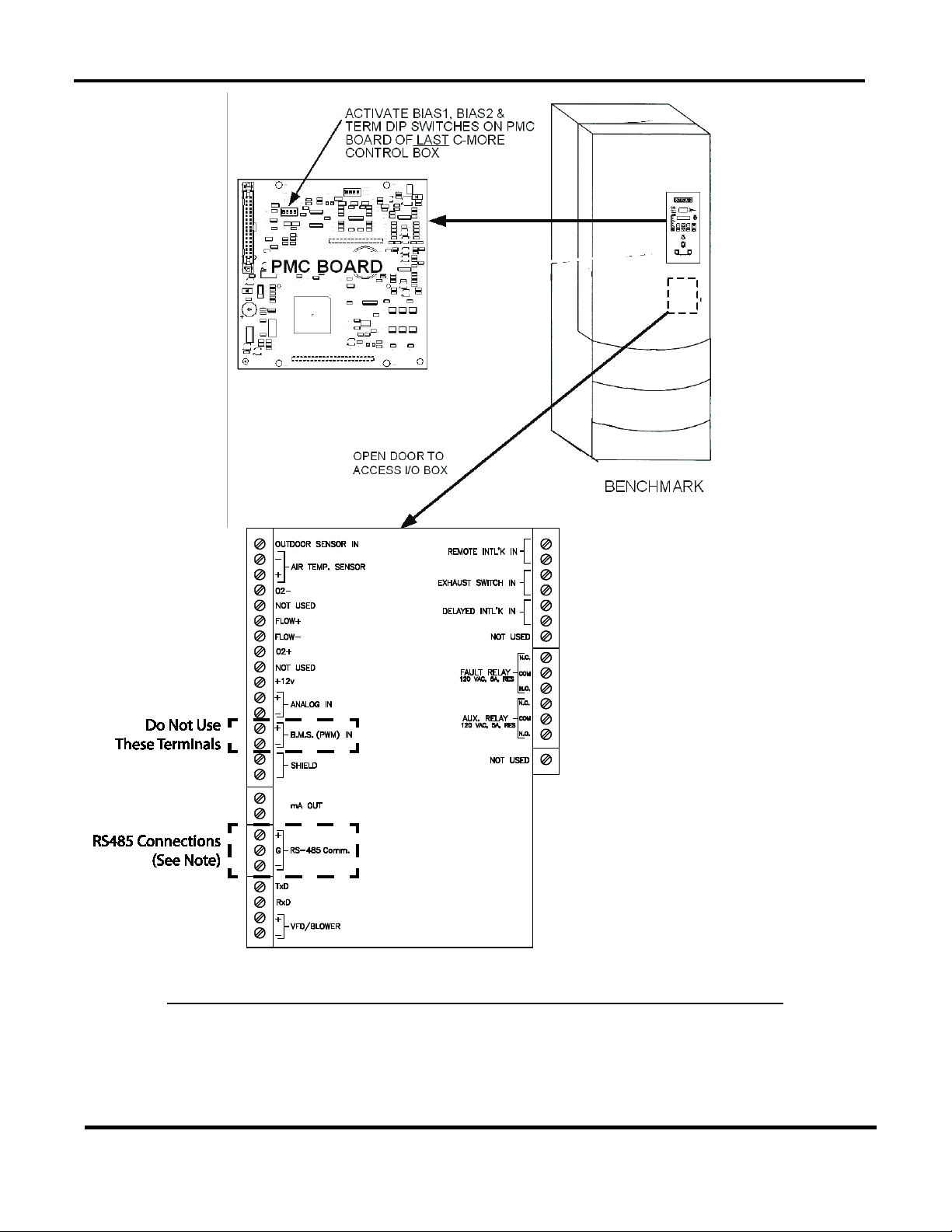
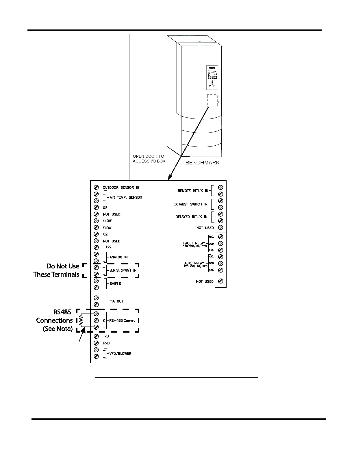
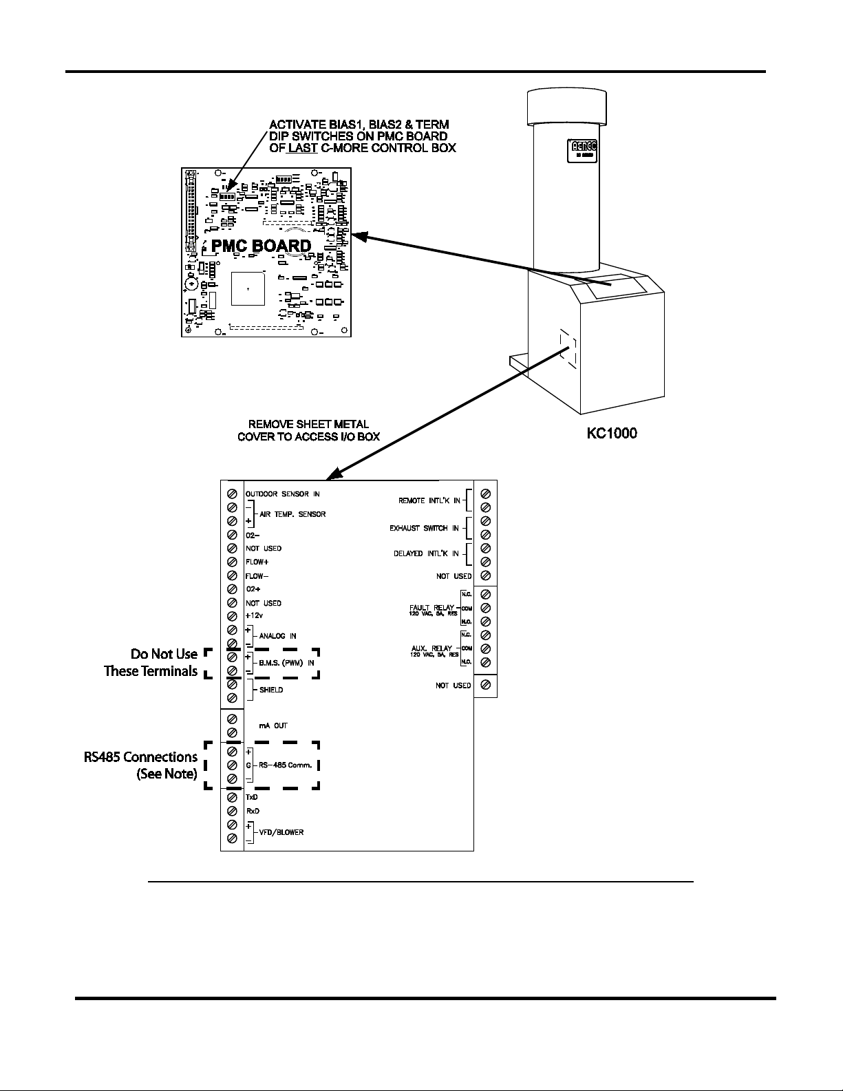
2.7.1 RS485 Wiring, Termination& Bias for Benchmark Series and KC1000 Boilers
RS485 wiring connections are made at the RS485 terminals of each boiler’s I/O Box (Figures 27 or 2-8). However, activating bias and loop termination can be performed using one of two
available methods as described below in Method A and on the following page in Method B.
Where possible, Method B is the preferred method.
Method A: For Method A, the bias switches in the ACS are left in the deactivated (up) position.
Bias and termination are controlled at the boiler end of the RS485 loop by activating the bias
and termination DIP switches on the PMC board of the last C-More Control Box on the daisychain. Refer to sheet 1 of Figure 2-7 (Benchmark), or Figure 2-8 (KC1000) and proceed as
shown below:
MC2: 04/23/13 Page 23 of 144
Page 24

GF-131
AERCO Control System (ACS)
AERCO International, Inc. • 100 Oritani Dr. • Blauvelt, New York 10913 • Phone: 800-526-0288
Installation, Operation, and Maintenance Manual
OMM-0081_0D
BIAS/Loop Term: METHOD A
towards the operator when using Method 1.
BIAS/Loop Term: METHOD B
in the down or toward the wall position toward the wall.
1. Using a daisy-chain wiring configuration, connect the RS485 positive lead to the RS485 +
terminal in the I/O Box for each boiler.
2. Connect the RS485 negative lead to the RS485 - terminal in the I/O Box for each boiler.
3. DO NOT terminate the shields to the Ground (GND) terminal at the boiler end of the RS485
loop. Connect the shields of the incoming and outgoing leads together. The RS485 loop shield
should only be terminated at terminal 3 of the ACS.
4. At the last boiler in the daisy-chain, activate the BIAS1, BIAS2 and TERM switches on the PMC
board in the C-More Control Box. Refer to GF-114, paragraph 4.3.2 for detailed instructions on
accessing the PMC board.
If an Oxygen Sensor is used, ensure that R1 DIP Switch is set to OFF (Disabled). Set it to ON
(Enabled) if there is no Oxygen Sensor used.
5. DO NOT activate the bias switches on the ACS. These switches must be in the up position
NOTE
With Method A, the last C-More on the daisy chain must remain powered
for the bus to be stable.
The advantage of using Method B is that the bias and termination of the
RS485 loop do not require any changes to be made to the DIP switches on
the PMC board in the last C-More Control Box. The bus is independent of
any C-More control box.
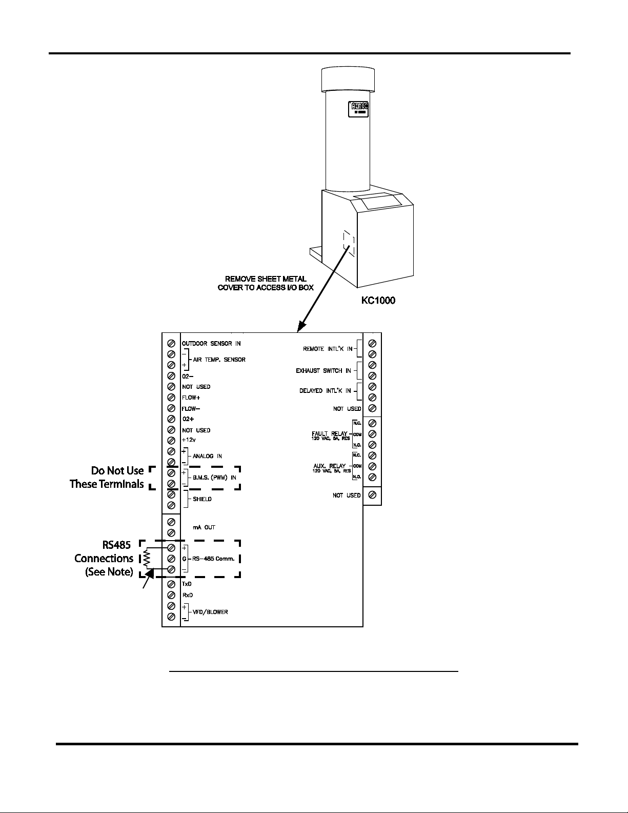
Method B: For Method B, bias is controlled at the ACS by setting the two bias switches (Figure
2-6) to the active (down) position. Termination at the boiler end of RS485 loop is accomplished
by activating the “MODBUS R6-ON” switch in the I/O Box in the last boiler on the daisy-chain. If
this is an older box, install a 120 ohm, 1/2 Watt termination resistor in the I/O Box of the last
boiler on the daisy-chain. Refer to sheet 2 of Figure 2-7 (Benchmark), or Figure 2-8 (KC1000)
and proceed as shown below:
1. Using a daisy-chain wiring configuration, connect the RS485 positive lead to the RS485 +
terminal in the I/O Box for each boiler.
2. Connect the RS485 negative lead to the RS485 - terminal in the I/O Box for each boiler.
3. DO NOT terminate the shields to the Ground (GND) terminal at the boiler end of the RS485
loop. Connect the shields of the incoming and outgoing leads together. The RS485 loop shield
should only be terminated at terminal 3 of the ACS.
4. At the last boiler in the daisy-chain, activate the “MODBUS R6-ON” dipswitch, or install a 120
ohm, 1/2 Watt termination resistor across the RS485 + and - terminals in the boiler’s I/O Box.
5. When using Method 2, activate the two bias switches in the ACS (Figure 2-6) by placing them
MC2: 04/23/13 Page 24 of 144
Page 25
GF-131
AERCO Control System (ACS)
AERCO International, Inc. • 100 Oritani Dr. • Blauvelt, New York 10913 • Phone: 800-526-0288
Installation, Operation, and Maintenance Manual
OMM-0081_0D
(GND) terminal. The shields
must be terminated at the
shields of the incoming and
I/O Board
Do not terminate the shields of
the RS485 leads to the ground
NOTE
source ends only. Connect the
outgoing RS485 leads together.
METHOD A – BIAS & TERMINATION ACTIVATED AT C-MORE PMC BOARD
Figure 2-7: RS485 (Modbus) Wiring For Benchmark Series Boilers (Sheet 1 of 2)
MC2: 04/23/13 Page 25 of 144
Page 26
GF-131
AERCO Control System (ACS)
AERCO International, Inc. • 100 Oritani Dr. • Blauvelt, New York 10913 • Phone: 800-526-0288
Installation, Operation, and Maintenance Manual
OMM-0081_0D
of the RS485 leads to the
at the source ends only.
Connect the shields of the
incoming and outgoing
Connect 120 OHM,
Box.
I/O Board
NOTE
Do not terminate the shields
ground (GND) terminal. The
shields must be terminated
RS485 leads together.
½ Watt resister
between + and –
RS485 terminals on
the LAST C-More
METHOD B – TERMINATION ACTIVATED AT I/O BOX
Figure 2-7: RS485 (Modbus) Wiring For Benchmark Series Boilers (Sheet 2 of 2)
MC2: 04/23/13 Page 26 of 144
Page 27
GF-131
AERCO Control System (ACS)
AERCO International, Inc. • 100 Oritani Dr. • Blauvelt, New York 10913 • Phone: 800-526-0288
Installation, Operation, and Maintenance Manual
OMM-0081_0D
(GND) terminal. The shields
must be terminated at the
shields of the incoming and
I/O Board
Do not terminate the shields of
the RS485 leads to the ground
NOTE
source ends only. Connect the
outgoing RS485 leads together.
METHOD A – BIAS & TERMINATION ACTIVATED AT C-MORE PMC BOARD
Figure 2-8: RS485 (Modbus) Wiring For KC1000 Boilers (Sheet 1 of 2)
MC2: 04/23/13 Page 27 of 144
Page 28
GF-131
AERCO Control System (ACS)
AERCO International, Inc. • 100 Oritani Dr. • Blauvelt, New York 10913 • Phone: 800-526-0288
Installation, Operation, and Maintenance Manual
OMM-0081_0D
(GND) terminal. The shields
must be terminated at the
shields of the incoming and
outgoing RS485 leads
Connect 120 OHM,
I/O Board
½ Watt resister
between + and –
RS485 terminals on
the LAST C-More
Box.
METHOD B – TERMINATION ACTIVATED AT I/O BOX
Figure 2-8: RS485 (Modbus) Wiring For KC1000 Boilers (Sheet 2 of 2)
MC2: 04/23/13 Page 28 of 144
Do not terminate the shields of
the RS485 leads to the ground
NOTE
source ends only. Connect the
together.
Page 29
GF-131
AERCO Control System (ACS)
AERCO International, Inc. • 100 Oritani Dr. • Blauvelt, New York 10913 • Phone: 800-526-0288
Installation, Operation, and Maintenance Manual
OMM-0081_0D
Y2
Y3
Y4
Y1
SW1
A1
I
0
BCM FRONT VIEW
7 6 5 4 3 2 1
Y2
JP2
JP1
T
C
V
JUMPER
SHOWN IN
“TERMINATED”
(UP) POSITION
MODBUS B (+)
MODBUS A (-)
RS485 Wiring at Boiler BCM of Modulex Boiler(s)
DO NOT terminate the shields at the Boiler end of the RS485 loop.
chain must have the termination jumper
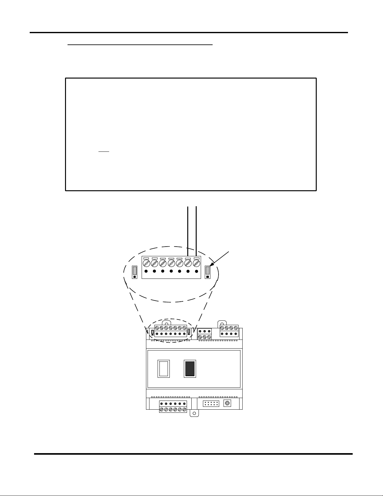
2.7.2 RS485 Wiring for Modulex Series Boilers
RS485 wiring connections are made at the MODBUS terminals of each Boiler’s BCM Module as
shown in Figure 2-9. Connect the wiring as shown below:
1. Connect the positive lead to terminal 1 (MODBUS B +) of connector Y2.
2. Connect the negative lead to terminal 2 (MODBUS A -) of connector Y2.
3.
Connect the shields of the incoming and outgoing leads together. The
RS485 loop shield should only be terminated at the ACS.
4. The last BCM in the daisyengaged as shown in Figure 2-9.
5. The two ACS bias switches (Figure 2-6) must be activated by placing them
in the down position.
MC2: 04/23/13 Page 29 of 144
Figure 2-9: RS485 (Modbus) Wiring For Modulex Series Boilers
Page 30
GF-131
AERCO Control System (ACS)
AERCO International, Inc. • 100 Oritani Dr. • Blauvelt, New York 10913 • Phone: 800-526-0288
Installation, Operation, and Maintenance Manual
OMM-0081_0D
NOTE
turned on. Refer to Section 2.7 of this
termination.
NOTE
be turned to “ON”.
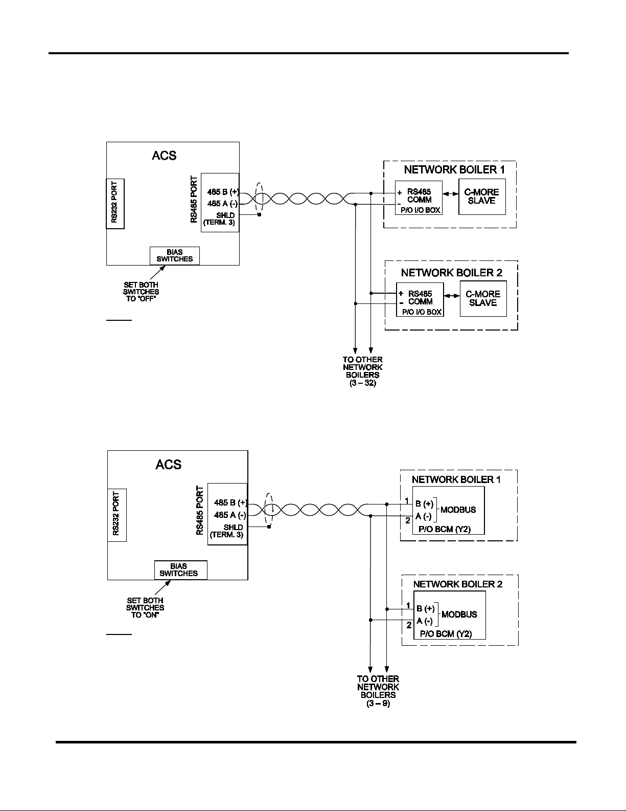
2.8 SAMPLE RS485 (MODBUS) NETWORK DIAGRAMS
Figure 2-10 shows a sample RS485 (Modbus) Network diagram with the ACS connected to
KC1000 or Benchmark Series Boilers equipped with C-More Control Systems. Figure 2-11
shows a similar sample diagram with the ACS connected to Modulex Series Boilers equipped
with BCMs and E8 Controllers.
The last C-More slave on the RS485 loop
must have its termination resister (TERM)
and bias (BIAS1, BIAS2) DIP Switches
manual for details on activating bias and
Figure 2-10: Sample RS485 (Modbus) Network For Benchmark or KC1000 Boilers
The last BCM slave on the RS485 loop
must have its termination resister (T)
activated. Refer to GF-115C for more
information.
The bias switches in the ACS should both
Figure 2-11: Sample RS485 (Modbus) Network For Modulex Series Boilers
MC2: 04/23/13 Page 30 of 144
Page 31

GF-131
AERCO Control System (ACS)
AERCO International, Inc. • 100 Oritani Dr. • Blauvelt, New York 10913 • Phone: 800-526-0288
Installation, Operation, and Maintenance Manual
OMM-0081_0D
2.9 RS485 WIRING AT THE ACS
The ACS communicates with an external Energy Management System (EMS) or Building
Automation System (BAS) utilizing the wiring terminals labeled RXD (Receive Data), TXD
(Transmit Data) and 232 ISO GND (Isolated Ground). If the EMS does not contain an RS232
port, a RS485-to-RS232 Converter (AERCO Part No. 124943) is required to communicate with
the ACS. If a Converter is required, it can be installed inside the wiring compartment of the ACS,
or installed externally. The ACS provides an isolated 12 VDC output terminal (ISO 12V) which
can be used to power AERCO’s RS485-to-RS232 Converter if needed. Refer to Figure 2-12 for
sample network layouts.
Figure 2-12: Sample Network Connections To EMS
MC2: 04/23/13 Page 31 of 144
Page 32

GF-131
AERCO Control System (ACS)
AERCO International, Inc. • 100 Oritani Dr. • Blauvelt, New York 10913 • Phone: 800-526-0288
Installation, Operation, and Maintenance Manual
OMM-0081_0D
CAUTION
2.10 INTERLOCK WIRING
The ACS is equipped with two interlocks designated Interlock 1 (INT 1) and Interlock 2 (INT 2).
Since both interlocks must be closed for the ACS to operate the boiler plant, the associated
wiring terminals are jumpered, prior to shipment. If desired, proving device switches can be
connected to either interlock in place of the jumper. If used, interlock wiring connections are
made as described in the following paragraphs.
DO NOT remove the factory-installed jumpers for INT1 or INT2
unless the respective Interlock is being connected to an external
proving device. The boiler plant WILL NOT operate if one or both
Interlocks remain open.
NOTE
If necessary, Interlock 1, Interlock 2 or both can be programmed to
operate the boilers only when the outdoor air temperature falls below
the system start temperature. The selection is made with “SYS
START INTLK” in the Relay Menu. The default is set to Interlock 1.
See paragraph 3.11 for details.
NOTE
NO power should be sent to the INT1, INT2, and SETBK terminals.
Only a dry contact may be applied.
2.10.1 Interlock 1 (INT 1) Wiring
Interlock 1 is often used with auxiliary equipment, such as air dampers or flow switches. It can
also be used as a general purpose interlock. If used, connect the end proving switch to INT 1
terminals 9 and 10 as shown in wiring diagram in Appendix E.
2.10.2 Interlock 2 (INT 2) Wiring
Similar to Interlock 1, Interlock 2 is a general purpose interlock which can be used with a variety
of devices or equipment or conditions that must be “proved” prior to enabling the boiler plant. If
used, connect the end proving switch to INT 2 terminals 11 and 12 as shown in wiring diagram
in Appendix E.
2.11 SETBACK WIRING
The SET BACK terminals, shown in the wiring diagram in Appendix E, are used only when
implementing a manually-controlled header temperature offset. If used, connect a dry contact
switch across SET BACK terminals 13 and 14. See the sub-section entitled Manual Offset
included in paragraph 3.8 (Field Adjust Menu),
2.12 RELAY WIRING
The ACS contains a System Start (SYS START) Relay, a Fault Alarm (FLT ALARM) Relay and
an Auxiliary (AUX) Relay which can be connected to external monitoring or control devices.
The contacts for each of these relays are rated at 120 VAC, 5A and are fused internally at 5A
with replaceable fuses. The contact terminals for these relays are shown in the wiring diagram
in Appendix E.
MC2: 04/23/13 Page 32 of 144
Page 33

GF-131
AERCO Control System (ACS)
AERCO International, Inc. • 100 Oritani Dr. • Blauvelt, New York 10913 • Phone: 800-526-0288
Installation, Operation, and Maintenance Manual
OMM-0081_0D
NOTE
The state of the SYS START, FLT ALARM and AUX Relays are
controlled by options contained in the Relay Menu described in
Chapter 3, paragraph 3.11.
2.12.1 System Start Relay
The state of the System Start (SYS START) relay contacts are controlled by the value set for
the SYS START TEMP and SYS START OPTION in the Relay Menu. The contacts are closed
either when the outdoor air temperature is less than the System Start Temperature (SYS
START TEMP) or when there is a load, or both. The default value for this temperature setting is
70°F. See paragraph 4.5 for additional information.
2.12.2 Fault Alarm Relay
The state of the Fault Alarm (FLT ALARM) relay contacts are controlled by the option selected
for the FAULT ALRM RELAY, FAULT ALARM BLR and FAULT ALRM CLEAR in the Relay
Menu. Contact closure can be set to: ALL FAULTS, NO INTERLOCK, INTERLOCK 2 or
INTERLOCK 1. The default for this option is ALL FAULTS.
2.12.3 Auxiliary Relay
The state of the Auxiliary (AUX) relay contacts are controlled by the AUX RELAY CLOSE and
AUX RELAY OPEN options selected in the Relay Menu. Contact closure can be set to occur
either when all available boilers are at the 100% Fire Rate or for either when all boilers are at
100% Fire Rate or no boilers are available (all boilers faulted or turned off).
2.13 4-20 MA WIRING
The ACS can accept a remote 4 – 20 mA current signal representing a setpoint. This input is
fused internally at 0.63A. Connect the signal leads to the 4-20 + and 4–20 – terminals. Refer to
Chapter 4, paragraph 4.3 for Remote Setpoint programming using a 4 -20 mA input.
2.14 MOUNTING AND WIRING THE OPTIONAL ACS RELAY BOX
The ACS (Aerco Control System) Relay Panel is used in combination with the ACS to control up
to 2 isolation valves, boiler interlocks, and a Domestic Hot Water (DHW) pump in a Combination
heating plant where AERCO boilers are bring used for both Building Heat and Domestic Hot
Water heating.
Figure 2-13: AERCO Control System (ACS) Relay Box
MC2: 04/23/13 Page 33 of 144
Page 34

GF-131
AERCO Control System (ACS)
AERCO International, Inc. • 100 Oritani Dr. • Blauvelt, New York 10913 • Phone: 800-526-0288
Installation, Operation, and Maintenance Manual
OMM-0081_0D
2.15 RELAY PANEL INSTALLATION AND WIRING
The ACS Relay Panel should be installed on a wall next to or as near as possible to the ACS.
The enclosure is the same as the ACS and so similar hardware can be used. See Section 2.2,
“Site Selection and Mounting” for further installation information.
Figure 2-14: AERCO Control System (ACS) Relay Box with Wiring Cover
Removed and Breakout Illustration of Connection Silk-Screening
MC2: 04/23/13 Page 34 of 144
Page 35

GF-131
AERCO Control System (ACS)
AERCO International, Inc. • 100 Oritani Dr. • Blauvelt, New York 10913 • Phone: 800-526-0288
Installation, Operation, and Maintenance Manual
OMM-0081_0D
Figure 2-14a shows sample wiring diagram of the relay box wiring and Figure 2-14b shows the
wiring to the ACS unit for a two-valve combination system. Your actual wiring may vary
depending on the type of valves being used:
Figure 2-14a: Wiring of the Relay Box (to the AERCO Control System (ACS)
MC2: 04/23/13 Page 35 of 144
Page 36

GF-131
AERCO Control System (ACS)
AERCO International, Inc. • 100 Oritani Dr. • Blauvelt, New York 10913 • Phone: 800-526-0288
Installation, Operation, and Maintenance Manual
OMM-0081_0D
Figure 2-14b: ACS Wiring: DHW Option 1
DHW Pump Enabled/Disabled by Building Controls
MC2: 04/23/13 Page 36 of 144
Page 37

GF-131
AERCO Control System (ACS)
AERCO International, Inc. • 100 Oritani Dr. • Blauvelt, New York 10913 • Phone: 800-526-0288
Installation, Operation, and Maintenance Manual
OMM-0081_0D
Figure 2-14c: ACS Wiring: DHW Option 2
DHW Pump Enabled/Disabled by ACS
MC2: 04/23/13 Page 37 of 144
Page 38

GF-131
AERCO Control System (ACS)
AERCO International, Inc. • 100 Oritani Dr. • Blauvelt, New York 10913 • Phone: 800-526-0288
Installation, Operation, and Maintenance Manual
OMM-0081_0D
Figure 2-14d: ACS Wiring: DHW Option 3
MC2: 04/23/13 Page 38 of 144
Page 39

GF-131
AERCO Control System (ACS)
AERCO International, Inc. • 100 Oritani Dr. • Blauvelt, New York 10913 • Phone: 800-526-0288
Installation, Operation, and Maintenance Manual
OMM-0081_0D
2.16 RELAY PANEL COMPONENTS
2.16.1 Power
The power connector is located at the left side of the wiring panel. It uses single phase AC
power from 110 to 240 VAC, 60 Hertz.
2.16.2 Inputs
The inputs are all dry switch (digital) inputs. The specifics are below:
• Aquastat In (Temperature) Switch
This switch input comes from the aquastat temperature switch located in the DWH
storage tank. The switch should have at least a 3 degree hysteresis or deadband.
• Valve End Switch In 1 & 2
These switch inputs come from the end switches of Valve 1 and Valve 2, respectively.
The valve end switches should close when the valves are completely open.
• Aux Relay Contact In
This switch input comes from the dry contact “Aux Relay” output of the ACS.
• Sys Relay Contact In
This switch input comes from the dry contact “Sys Relay” output of the ACS.
2.16.3 Outputs
The relay outputs are all dry contact and can switch up to 5A at 120VAC, or ?240 VAC. The
switch outputs connect directly to the ACS and are all dry contacts. The specifics are below:
• DHW Pump Relay
This SPST relay is used to activate a DHW pump when the DHW Aquastat is calling for
heat. When the Aquastat stops calling, the relay will remain activated for ?1 minute
before turning off.
• Valve I Relay
This SPDT relay controls the valve between the Building Priority boilers and the DHW
Priority boilers. The Normally Open (N.O.) contact is connected to the Valve 1 Open
and the Normally Closed (N.C.) contact is connected to the Valve 1 Close input. For a
valve with “spring return open” or “capacitor return open”, the N.O. contact would not be
used.
• Valve 2 Relay
This SPDT relay controls the valve between the Building boilers and the Building Priority
boilers. The Normally Open (N.O.) contact is connected to the Valve 2 Close and the
Normally Closed (N.C.) contact is connected to the Valve 2 Open input. For a valve with
“spring return open” or “capacitor return open”, the N.C. contact would not be used.
Interlock 1
4 Relay – These are 4 SPST relays used to enable or disable the Building Priority boilers
in this 2-valve system.
• Aquastat Switch Out
This SPST contact connects to the “Setback” input of the ACS.
• Valve End Switch Out
This SPST contact connects to the “Interlock 1” input of the ACS.
MC2: 04/23/13 Page 39 of 144
Page 40

GF-131
AERCO Control System (ACS)
AERCO International, Inc. • 100 Oritani Dr. • Blauvelt, New York 10913 • Phone: 800-526-0288
Installation, Operation, and Maintenance Manual
OMM-0081_0D
2.17 RELAY PANEL OPERATION
Clear Plastic
Cover
Wiring Compartment Cover
Front Panel
Figure 2-15: ACS Relay Panel Front Panel
The board operates basically as follows:
a) In the normal idle state, all the inputs, except one of the Valve End Switch In inputs, would
be open. As a result, the Aquastat Out would be open and the Valve End Switch Out would
be closed. All the relays except the Interlocks Relay will be in their unpowered state – DHW
Pump off, Valve 1 closed(N.C. powered), and Valve 2 open (N.C. powered). Since the
Valve End Switch Output would be activated, all the Interlocks relays will be activated and
all its contacts closed thereby enabling the Building Priority boilers to run if needed.
NOTE
If no Valve 2 (Sys Relay) is used, the Interlocks Relay connection
will not need to be used.
b) When the tank calls for heat and the Aquastat Input closes, the DHW Pump relay will
activate. The ACS will activate Valve 1 to close if it is not already closed. Once closed the
ACS will allow the DHW Priority boilers to run to provide heat to the tank.
If all the DHW Priority boilers are running at 100% for more than 2 minutes, the ACS will
open Valve 1 and close Valve 2 and activate the Building Priority boilers to help with DHW
heating.
When the Aquastat Input opens, the DHW Pump will turn off after some time delay (currently
60 seconds). The DHW Priority boilers will also shut down and Valve 1 will close and Valve
2 open.
c) Generally if any of the two valves is fully open and its Valve End Switch Input closes, the
Interlock relays will activate to allow the Building Priority boilers to run. When the Valve End
Switch Input opens, the Interlock relays will de-activate.
d) The Valve 1 Relay output is labeled such that the Normally Closed (N.C.) contact is Valve 1
Close and the Normally Open (N.O.) contact is Valve 1 Open. The Valve 2 Relay output is
labeled such that the Normally Closed (N.C.) contact is Valve 2 Open and the Normally
Open (N.O.) contact is Valve 2 Close. It is important to make these connections correctly. In
this way, the unpowered state of the relay panel will keep the valves in the default state with
Valve 1 closed and Valve 2 open.
MC2: 04/23/13 Page 40 of 144
Page 41

GF-131
AERCO Control System (ACS)
AERCO International, Inc. • 100 Oritani Dr. • Blauvelt, New York 10913 • Phone: 800-526-0288
Installation, Operation, and Maintenance Manual
OMM-0081_0D
2.18 ACS PROGRAMMING FOR USE WITH THE ACS RELAY PANEL
The AERCO CONTROL SYSTEM (ACS) can be programmed for 3 different types of DHW
options. For “Option 1” and “Option 3” operation, the ACS Relay Panel is not needed. It is
needed for Option 2 operation.
Below we will illustrate programming the ACS for a total of 8 boilers with 2 DHW Priority boilers,
2 Building Priority boilers, and the rest Building boilers. Valve 1 is in the boiler outlet header
between the Building Priority boilers and the DHW Priority boilers. Valve 2 is in the boiler outlet
header between the Building boilers and the Building Priority boilers. Program the ACS as
follows:
2.18.1 RS485 Menu
1) In the RS485 Menu be sure to include all the boilers being controlled via Modbus in the
“NUMBER NETWK BLRS” number.
2) When programming “NETW BOILER XX ADDRESS” include the number of DHW Priority
boilers and Building Priority boilers at the end of the addresses up to “NETW BOILER 32
ADDRESS”. For our example, you would program them as follows:
a) Building boilers would be programmed at NETW BOILER 1 ADDRESS, NETW
BOILER 2 ADDRESS, NETW BOILER 3 ADDRESS, and NETW BOILER 4 ADDRESS.
Building Priority boilers would be programmed at NETW BOILER 29 ADDRESS and
NETW BOILER 30 ADDRESS. DHW Priority boilers would be programmed at NETW
BOILER 31 ADDRESS and NETW BOILER 32 ADDRESS.
2.18.2 Configuration Menu
1) For “DHW OPTION” select OPTION 2. This will trigger other sub-menus to appear.
2) Set “NUMBER DHW BLRS” to 4 to indicate that our system will have 4 boilers that can be
used to help with DHW heating – 2 Building Priority and 2 DHW Priority.
3) Set “DHW SIGNAL” to the signal the C-more requires to do DHW heating when it is set for
Combination mode. Currently it is “No Signal”.
4) Set “Valve Wait State” to the state in which you want the DHW boilers to remain while the
valve is opening. If “Off” is selected, they will be commanded to shut down, if they were
running. If “On” is selected and any were fired, they will remain fired while the valve is
opening as long as the Valve End Switch is made within the “Valve Wait Time”(with a default
of 120 seconds). Of course if the boiler interlocks are opened during this time, the boilers
will shut down.
5) Set “NUM DHW PRIORITY” to 2 to indicate that 2 of the boilers are DHW Priority boilers.
The rest will be assumed to be Building Priority boilers.
The steps above will program the ACS to operate with the ACS Relay Panel. You would adjust
the number of boilers to your particular system.
MC2: 04/23/13 Page 41 of 144
Page 42

GF-131
AERCO Control System (ACS)
AERCO International, Inc. • 100 Oritani Dr. • Blauvelt, New York 10913 • Phone: 800-526-0288
Installation, Operation, and Maintenance Manual
OMM-0081_0D
(This page intentionally blank)
MC2: 04/23/13 Page 42 of 144
Page 43

GF-131
AERCO Control System (ACS)
Installation, Operation, and Maintenance Manual
OMM-0081_0D
AERCO International, Inc. • 100 Oritani Dr. • Blauvelt, New York 10913 • Phone: 800-526-0288
1 6 2 3 5
4
3. OPERATION
3.1 INTRODUCTION
The information in this Chapter provides a guide to the operation of the ACS using the controls
and display mounted on the front panel of the unit. This Chapter describes the basic procedure
to navigate through the extensive array of menus and options incorporated in the ACS design.
Descriptions for all menus and options are also provided.
3.2 FRONT PANEL OPERATING CONTROLS AND DISPLAYS
The front panel of the ACS contains an vacuum fluorescent display (VFD) and an 8-key touchpad. The display and controls are illustrated and described in Figure 3-1 and Table 3-1
respectively.
Figure 3-1: ACS Front Panel Controls and Displays
MC2: 04/23/13 Page 43 of 144
Page 44

GF-131
AERCO Control System (ACS)
AERCO International, Inc. • 100 Oritani Dr. • Blauvelt, New York 10913 • Phone: 800-526-0288
Installation, Operation, and Maintenance Manual
OMM-0081_0D
DISPLAY
Menu Selections
6
ON Indicator
Green ON LED lights when the ACS is enabled.
Table 3-1: ACS Front Panel Controls and Display
ITEM
NO.
1 VFD Display The Vacuum Fluorescent Display (VFD) display consists of 2
2 FAULT Indicator Red FAULT LED indicator lights when a ACS alarm condition
3 CLEAR Key
4
MENU Steps through the main menu categories shown in Figure 2-1.
CONTROL,
INDICATOR OR
lines each capable of displaying up to 16 alphanumeric
characters. The information displayed includes:
• Startup Messages
• Alarm Messages
• Operating Status Messages
•
occurs. An alarm message will also appear in the VFD display.
Turns off the FAULT indicator and relay if FAULT ALRM CLEAR
is set to Manual and the fault is still active or no longer active. If
FAULT ALRM CLEAR is set to Automatic and the fault is still
active, this will also turn off the fault relay and indicator. In both
cases the alarm message will remain until the alarm is no longer
valid.
MENU Keypad Consists of 6 keys which provide the following functions for the
ACS menus:
The Menu categories wrap around in the order shown.
FUNCTION
BACK Allows you to go back to the previous menu level without
changing any information. Continuously pressing this key will
bring you back to the default status display in the Operating
Menu. Also, this key allows you to go back to the top of a main
menu category.
▲ (Up) Arrow When in one of the main menu categories, pressing this key will
move you forward through the displayed menu category. If the
CHANGE key was pressed and the menu item is flashing, press
the ▲ arrow key increment the setting.
▼ (Down) Arrow When in one of the main menu categories, pressing this key will
select the displayed menu category. If the CHANGE key was
pressed and the menu item is flashing, pressing the ▼ (Down)
arrow key will decrement the selected setting.
CHANGE Permits a setting to be changed (edited). A valid password
must be entered before changing most menu items. When the
CHANGE key is pressed, the displayed menu item will alternate
in color with the background (reverse video). Pressing the ▲ or
▼ arrow key when this occurs will increment or decrement the
displayed setting.
ENTER Saves the modified menu information in memory. The display
will return to the normal state.
5 ON/OFF Key Enables and disables ACS operation.
MC2: 04/23/13 Page 44 of 144
Page 45

GF-131
AERCO Control System (ACS)
AERCO International, Inc. • 100 Oritani Dr. • Blauvelt, New York 10913 • Phone: 800-526-0288
Installation, Operation, and Maintenance Manual
OMM-0081_0D
Menu Processing Procedure
3.3 ACS MENU STRUCTURE
The ACS incorporates an extensive menu structure which permits the operator to set up, and
configure the unit. The menu structure consists of nine major menu categories as shown in
Figure 3-2. Each of the menus shown, contain options which permit operating parameters to be
viewed or changed. The menus are protected by two different password levels to prevent
unauthorized use. These passwords provide access as follows:
• Password Level 1 (159) allows viewing of all menu categories. In addition, this Password
Level allows all Menu options to be changed, except for Calibration Menu options.
• Password Level 2 (6817) allows viewing and changing of the options contained in the
Calibration Menu. In addition, it allows all Level 1 menu categories to be viewed or
changed. The Calibration Menu should only be used by factory-trained personnel.
Prior to entering the correct password, the options contained in all of the Menu categories
(except the Calibration Menu) can be viewed. However, except for Internal Setpoint
Temperature (Field Adjust Menu), none of the viewable menu options can be changed.
Once the valid Level 1 (159) or Level 2 (6817) password is entered, the options listed in the
available menus can be viewed and changed, if desired.
3.3.1 Menu Processing Procedure
Accessing each menu and option is accomplished using the Menu Keys shown in Figure 3-1.
Therefore, it is imperative that you be thoroughly familiar with the following basic steps shown in
Instruction 3.1.1 before attempting to perform specific menu processing procedures.
1. The ACS will normally be in the Operating Menu and the VFD will display the current
unit status. Pressing the ▲ or ▼ arrow key will display the other available data in the
Operating Menu.
2. Press the MENU key. The display will show the Setup Menu which is the next menu
category shown in Figure 3-2. This menu contains the Password option which must be
entered if other menu options will be changed.
3. Continue pressing the MENU key until the desired menu is displayed.
4. With the desired menu displayed, press the ▲ arrow key. The first option in the selected
menu will be displayed.
5. Continue pressing the ▲or ▼ arrow key until the desired menu option is displayed.
Pressing the ▲ arrow key will display the available menu options in the Top-Down
sequence. Pressing the ▼ arrow key will display the options in the Bottom-Up
sequence. The menu options will stop when the last option is reached, going forward, or
the first option is reached, going backwards. They do not wrap-around after the first or
last available option.
6. To change the value or setting of a displayed menu option, press the CHANGE key.
The displayed option will appear in reverse video. Press the ▲ or ▼ arrow key to scroll
through the available menu option choices for the option to be changed. The menu
option choices do not wrap around.
7. To select and store a changed menu option, press the ENTER key.
MC2: 04/23/13 Page 45 of 144
Page 46

GF-131
AERCO Control System (ACS)
AERCO International, Inc. • 100 Oritani Dr. • Blauvelt, New York 10913 • Phone: 800-526-0288
Installation, Operation, and Maintenance Manual
OMM-0081_0D
OPERATING
SETUP
RS232
RS485
FIELD ADJUST
CONFIGURATION
TUNING
RELAY
CALIBRATION
LEVEL 1 PWD
LEVEL 2 PWD
MC2: 04/23/13 Page 46 of 144
Figure 3-2: ACS Menu Structure
Page 47

GF-131
AERCO Control System (ACS)
AERCO International, Inc. • 100 Oritani Dr. • Blauvelt, New York 10913 • Phone: 800-526-0288
Installation, Operation, and Maintenance Manual
OMM-0081_0D
NOTE
Paragraphs 3.4 through 3.12 provide detailed descriptions of the
options contained in each of the menus shown in Figure 3-2. The menu
options appear in the first line of the VFD display and the corresponding
value or setting for the displayed option will appear in the second line of
the display.
Refer to Appendix A for tabular summaries of all menu options showing
the allowable entry ranges and default values.
3.4 OPERATING MENU
The Operating Menu displays a number of key operating parameters for the ACS: These
parameters include:
HEADER TEMP, HEADER SETPOINT, OUTSIDE AIR TEMP, PERCENT OF LOAD, I/O
STATUS and RETURN TEMP (with optional Temperature Sensor).
All of the items in this menu are “Read-Only” and do not allow personnel to change or adjust
any of the displayed parameters. Since this menu is “Read Only”, it can be viewed at any time
without entering a password. The Operating Menu options are described in the paragraphs
which follow.
3.4.1 HEADER TEMP AND PERCENT OF LOAD
The HEADER TEMP menu option displays the actual water temperature (°F) measured by the
Header Sensor connected to HDR SEN terminals 4 and 5 of the ACS. If the Header Sensor is
not installed, HDR SENS ERROR will appear in the first line of the display. The red FAULT
indicator will also light. The Header Sensor MUST be installed for the ACS to operate properly.
The PERCENT OF LOAD option shows the percent level going from the ACS to each boiler in
the boiler plant. It also shows the number of boiler units that are operating.
NOTE
The ACS will shut down the last boiler firing when the Percent Output
Level goes below the BLR STOP LEVEL. The shutdown will be
indicated by the second line of the default display flashing. By the same
token, as the Percent Level Output rises from 0%, the second line of the
default (Operating Menu) display will flash until it reaches the BLR
START PERCENT and the Header temperature is below 'Setpoint DEMAND OFFSET.
3.4.2 HEADER SETPOINT
This menu option is the setpoint temperature to which the control is set when operating in the
Constant Setpoint, Remote Setpoint or Outdoor Reset Mode. When in the Constant Setpoint
Mode, this value is equal to the Internal Setpoint setting in the Configuration Menu. When in the
Remote Setpoint Mode, this value is the setpoint equivalent to the remote analog signal or
Modbus value supplied to the unit. When in the Outdoor Reset Mode, this is the derived value
from the charts in Appendix D.
3.4.3 OUTSIDE AIR TEMP
The OUTSIDE AIR TEMP option shows the outdoor air temperature (°F) measured by the
Outdoor Air Sensor. This sensor is connected to OUT AIR SENS terminals 1 and 2 of the ACS.
MC2: 04/23/13 Page 47 of 144
Page 48

GF-131
AERCO Control System (ACS)
AERCO International, Inc. • 100 Oritani Dr. • Blauvelt, New York 10913 • Phone: 800-526-0288
Installation, Operation, and Maintenance Manual
OMM-0081_0D
Bit
3
Bit
2
Bit
1
Bit
0
8
4 2 1
If LSD = 0: All Relay Outputs Off
LSD
Bit
3
Bit
2
Bit
1
Bit
0
8
4 2 1
If MSD = 0: All Inputs Open
If MSD = 8-16: Not Valid
MSD
If the Sensor is not connected, the second line of the display will show NOT CONNECTED. The
Outdoor Air Sensor MUST be connected when operating in the Outdoor Reset Mode.
3.4.4 I/O STATUS
I/O (Input/Output) STATUS is displayed as a hexadecimal number. The meaning of each bit is
as indicated below. The higher 4 bits, or most significant digit (MSD), indicate which inputs are
activated. The lower 4 bits, or least significant digit (LSD), indicate which relay outputs are
activated. See Appendix B for full list.
Value When Set:
If MSD = 1: Setback Closed
If MSD = 2: Interlock 2 Closed
If MSD = 3: Setback and Interlock 2 Closed
If MSD = 4: Interlock 1 Closed
If MSD = 5: Setback and Interlock 1 Closed
If MSD = 6: Interlock 1 and Interlock 2 Closed
If MSD = 7: Setback, Interlock 2,
and Interlock 2 Closed
If LSD = 1: Aux Relay On
If LSD = 2: Fault Relay On
If LSD = 3: Aux and Fault Relays On
If LSD = 4: System Relay On
If LSD = 5: System and Aux Relays On
If LSD = 6: System and Fault Relays On
If LSD = 7: Aux, Fault, and System
Relays On
If LSD = 8-16: Not Valid
3.4.5 RETURN TEMP
The RETURN TEMP (°F) option is displayed only if an optional Return Sensor is installed in the
boiler water return line. When installed, it is connected to terminals 5 and 6 on the ACS. This
optional sensor is used for monitoring purposes, as well as for Plant DT limit operation.
3.4.6 NETWORK BOILER OUTLET TEMPERATURE
When BLR CNTL SELECT is set to C-More or BCM, the outlet temperature of the boilers
connected may be viewed here. Press the Change Key to view the other temperatures. Press
Enter to stop at a particular boiler temperature.
3.4.7 NETWORK BOILER ERROR CODE
When BLR CNTL SELECT is set to C-More or BCM, the Status or Error Codes of the boiler may
be viewed here. Press the Change Key and then, Up or Down keys to view the other
temperatures. Press Enter to stop at a particular boiler code. See Appendix B for definition of
codes.
3.5 SETUP MENU
The SETUP MENU permits the operator to set the unit password which is required to change
any of the menu options. To prevent unauthorized use, a previously entered password entry will
time-out after 1 hour. Therefore, the password must be re-entered when required. In addition to
MC2: 04/23/13 Page 48 of 144
Page 49

GF-131
AERCO Control System (ACS)
AERCO International, Inc. • 100 Oritani Dr. • Blauvelt, New York 10913 • Phone: 800-526-0288
Installation, Operation, and Maintenance Manual
OMM-0081_0D
permitting password entries, the SETUP MENU is also used to enter the date and time.
Descriptions of the SETUP MENU options follow.
3.5.1 ENTER PASSWORD
The ENTER PASSWORD option allows the Level 1 (159) or Level 2 (6817) to be entered.
Once the valid Level 1 password (159) is entered, options in all Menus, except the Calibration
Menu, can be changed.
The Level 2 password (6817) must be entered to view or change options in the Calibration
Menu. Only factory trained personnel should use this Menu.
To enter a password, press CHANGE, and then the UP or DOWN button to select each digit.
Press Change after each digit is selected in order to advance to the next digit. Press Enter when
the desired password is displayed
3.5.2 DATE AND TIME MENU OPTIONS
The Setup Menu options associated with date and time are as follows:
SET MONTH 01 -12
SET DATE 01 – 31
SET YEAR 00 – 99
SET HOUR 00 -23
SET MINUTE 00 – 59
SET DAY OF WEEK SUNDAY TO SATURDAY
3.6 RS232 MENU
The RS232 MENU options permit the ACS to communicate with an external Energy
Management System (EMS) or Computer via the RS232 Port wiring terminals labeled RXD,
TXD, ISOGND on the ACS. The RS232 Menu options are used to select the RS232 Mode,
Baud Rate, Modbus Address, Network Timeout period and Modbus Pass-Thru feature for the
ACS.
3.6.1 RS232 MODE
The RS232 MODE option allows the selection of the type of communication desired at the
RS232 port: NORMAL (dumb terminal) or MODBUS SLAVE (Modbus Protocol). When the ACS
is being controlled by an external Energy Management System (EMS), via Modbus Protocol, set
this option to MODBUS SLAVE (default). If the EMS being used contains only a RS485 port, a
RS485-to-RS232 Converter is required.
3.6.2 RS232 BAUD RATE
The RS232 BAUDRATE option sets the communication Baud Rate between the ACS and the
EMS. Available settings include 2400, 4800, 9600 (default), or 19200. Both the ACS and EMS
MUST be set to the same baud rate to enable the communication link.
3.6.3 MODBUS ADDRESS
The MODBUS ADDRESS option sets the ACS address when operating as a Slave on a
Modbus Network. The address can be set from 128 (default) to 247.
MC2: 04/23/13 Page 49 of 144
Page 50

GF-131
AERCO Control System (ACS)
AERCO International, Inc. • 100 Oritani Dr. • Blauvelt, New York 10913 • Phone: 800-526-0288
Installation, Operation, and Maintenance Manual
OMM-0081_0D
3.6.4 NETWORK TIMEOUT
When the ACS is operating in the Remote Setpt mode via Modbus, the NETWORK TIMEOUT
option defines the maximum time (seconds) allowed before re-sending the setpoint information.
If the information is nozt re-sent within this time period, the ACS will default to its Failsafe mode
of operation set in the Configuration Menu and display “MODBUS TIMEOUT ERROR”. The
network timeout period is selectable from 005 to 240 seconds (Default = 060).
3.6.5 MODBUS PASS THRU
When enabled, the MODBUS PASS THRU option allows an EMS or computer, communicating
from the RS232 port, to access information from the boilers connected on the RS485 port of the
ACS. When enabled, it allows boiler monitoring and setup but not direct control of the boilers.
To enable writing to the boiler control, you must go to the Calibration Menu and enable
“PASSTHRU WRITE”.
3.7 RS232 MENU
The ACS communicates with the connected AERCO network boilers via its RS485 (Modbus)
Port (485 B+ and 485 A-). Therefore, the RS485 Menu contains the options necessary to enable
communication between the ACS and the connected network boiler slaves. Each network boiler
on the Modbus network must be assigned a unique address to enable communication.
The RS485 Menu options are used to select the RS232 Baud Rate, Min./Max. Range of Slave
Addresses, Total Number of Networked Boilers, Type of Modbus Control and the Unique
Address for each Networked Boiler. Descriptions of these options follow.
The ACS can automatically detect boilers within the “”Min Slave Addr” and “Max Slave Addr”
range, or you can program the boiler addresses in the order desired. AERCO recommends
programming the addresses in the desired order. When programming the boiler addresses, set
the “Min Slave Addr” and “Max Slave Addr” to zero.
3.7.1 RS485 BAUD RATE
The RS485 BAUDRATE option Sets the communication baud rate for the Modbus network
between the ACS and the Boilers connected to the RS485 terminals [B(+), A(-)]. Available
settings are 2400, 4800, 9600 (default), or 19200.
3.7.2 MIN SLAVE ADDR
The MIN SLAVE ADDR sets the Minimum Slave Address for the Boilers being controlled on the
RS485 (Modbus) Network when automatic boiler detection is desired; otherwise, leave set to
zero. Allowable entry range is 000 to 127 (default = 000).
3.7.3 MAX SLAVE ADDR
The MAX SLAVE ADDR Sets the Maximum Slave Address for the Boilers being controlled on
the RS485 (Modbus) Network when automatic boiler detection is desired; otherwise, leave set
to zero. Allowable entry range is 000 to 127 (default = 000).
3.7.4 NUMBER NETWK BLRS
This menu option sets the Number of Network Boilers connected to the ACS RS485 (Modbus)
terminals. Up to 32 Boilers can be connected to the Network (default = 02).
3.7.5 MODBUS CNTL TYPE
This menu option sets the Modbus Control Type to ROUND ROBIN or BROADCAST. Only
MC2: 04/23/13 Page 50 of 144
Page 51

GF-131
AERCO Control System (ACS)
AERCO International, Inc. • 100 Oritani Dr. • Blauvelt, New York 10913 • Phone: 800-526-0288
Installation, Operation, and Maintenance Manual
OMM-0081_0D
ROUND ROBIN can be used at this time. When set to ROUND ROBIN, each networked boiler
is addressed individually in sequence. BROADCAST is currently not used for the ACS.
3.7.6 NETW BOILER Xx ADDRESS=Yyy
Up to 32 Network Boilers can be accommodated on the Modbus Network (Where Xx = 01 – 32
and Yyy = 001 – 127). Each Boiler must be assigned a unique address on the network ranging
from 001 to127. No addresses should be entered if automatic boiler detection is desired. Simply
set the MIN SLAVE ADDR and MAX SLAVE ADDR to the minimum and maximum address
range of the boilers. To program boiler addresses in the order you desire, enter them here and
set the MIN SLAVE ADDR and MAX SLAVE ADDR to zero.
3.8 FIELD ADJUST MENU
The FIELD ADJUST MENU contains the most extensive list of options compared to the other 8
Menu categories. The options in this menu allow you to adjust important parameters to suit the
specific needs of your ACS installation. Included are options to select the Header Mode and
Temperature Limits, Internal Setpoint, Building Reference Temperature, Reset Ratio and
Remote Signal. In addition, the Field Adjust Menu contains a series of options which can be
used to set up a Header Setpoint Offset Schedule for an entire week. Descriptions of the Field
Adjust Menu options:
3.8.1 HEADER SET MODE
The HEADER SET MODE option sets the Header Setpoint selection method for the ACS.
Allowable selections are: CONSTANT SETPT, OUTDOOR RESET or REMOTE SETPT.
(Default = CONSTANT SETPT).
3.8.2 HDR HIGH LIMIT
The HDR HIGH LIMIT option sets the maximum temperature setting allowed for the Header
Setpoint. This setting also defines the 20 mA temperature equivalent when operating in the
Remote Setpoint Mode using a 4 – 20 mA signal. The allowable setting range is from the HDR
LOW LIMIT to 220°F. (Default = 200°F).
3.8.3 HDR LOW LIMIT
The HDR LOW LIMIT menu option sets the minimum temperature setting allowed for the
Header Setpt. This setting also defines the 4 mA temperature equivalent when operating in the
Remote Setpoint Mode using a 4 – 20 mA signal. The setting range is from 40°F to the HDR
HIGH LIMIT. (Default = 40°F).
3.8.4 INTERNAL SETPT
The INTERNAL SETPT temperature is the HEADER SETPT used when CONSTANT SETPT is
selected for the HEADER SET MODE or when the ACS operates in the Failsafe Mode and
CONSTANT SETPT is selected as the FAIL SAFE MODE setting in the Configuration Menu.
3.8.5 RESET RATIO
This menu option is displayed only if the HEADER SET MODE is set to OUTDOOR RESET.
The RESET RATIO option setting defines the ratio of the increase in Header temperature with
respect to each degree decrease in Outdoor temperature starting from the Building Reference
Temperature (BLDG REF TEMP).
The Reset Ratio is adjustable from 0.3 to 3.0. (Default = 1.2). The Reset Ratio Charts provided
in Appendix D are suitable for most applications. However, if a special reset schedule is desired,
MC2: 04/23/13 Page 51 of 144
Page 52

GF-131
AERCO Control System (ACS)
AERCO International, Inc. • 100 Oritani Dr. • Blauvelt, New York 10913 • Phone: 800-526-0288
Installation, Operation, and Maintenance Manual
OMM-0081_0D
the calculation method described in Appendix D must be used.
3.8.6 BLDG REF TEMP
The BLDG REF TEMP menu option is only displayed when the HEADER SET MODE is set to
OUTDOOR RESET. This option is used to set the Building Reference Temperature (BLDG REF
TEMP) to the desired value from 40°F to 220°F. (Default = 70°F).
3.8.7 REMOTE SIGNAL
The REMOTE SIGNAL menu option is only displayed when the HEADER SET MODE is set to
REMOTE SETPT. When displayed, this option is used to select the controlling remote signal: to
4 – 20 mA or MODBUS. (Default = 4-20 mA).
3.8.8 OFFSET ENABLE
The OFFSET ENABLE menu option is used to turn ON, or turn OFF the Setpoint Temperature
Offset feature. (Default = OFF)
3.8.9 Offset Menu Options
The Field Adjust Menu contains a series of menu options which permit an offset schedule to be
set up for a 7-day period (Sunday through Saturday). For each day (Sunday – Saturday), these
options include:
OFFS TEMP [Setpoint Offset Temperature (-50°F to +50°F)]
ON HOUR (00 to 23)
ON MINUTE (00 to 59)
OFF HOUR (00 to 23)
OFF MINUTE (00 to 59)
Normally, if an Offset Schedule is used, it is controlled automatically using the set-up
procedures described in the paragraph titled “Setting Up An Offset Reset Schedule” However, if
desired, the header offset can be controlled manually by connecting a switch across the SET
BACK wiring terminals 13 and 14 as shown in the wiring diagram in Appendix E. If a manual
offset is used, refer to the paragraph titled “Manual Offset”.
3.8.10 Setting Up an Offset Schedule
The steps involved in setting up an automatic reset schedule consists first of selecting the
temperature offset and then entering the start and stop times for which the offset will be in
effect. Note that the ACS uses a 24-hour clock (00;00 to 23:59). The steps are outlined in
Instruction 3.8.1. In this example, the setpoint temperature is being offset -15°F on Sunday
from 12:01 AM (00:01) to 8:00 AM (08 hrs).
MC2: 04/23/13 Page 52 of 144
Page 53

GF-131
AERCO Control System (ACS)
AERCO International, Inc. • 100 Oritani Dr. • Blauvelt, New York 10913 • Phone: 800-526-0288
Installation, Operation, and Maintenance Manual
OMM-0081_0D
Setting Up an Offset Schedule
Setting Up a Manual Offset Schedule
programmed OFFS TEMP for that day. Opening the SET BACK switch will disable the
1. Scroll through the FIELD ADJUST MENU and select OFFSET ENABLE. Set this option
to ON.
2. Next, scroll to SUN OFFS TEMP and set the Offset Temperature to -15°F.
3. Press the ▲ arrow key. SUN ON HOUR will be displayed. Set the HOUR to 00.
4. Press the ▲ arrow key again. SUN ON MINUTE will be displayed. Set the MINUTE to
01.
5. Press the ▲ arrow key again. SUN OFF HOUR will be displayed. Set the HOUR to 08.
6. Press the ▲ arrow key again. SUN OFF MINUTE will be displayed. Set the MINUTE to
00.
7. Repeat steps 2 through 6 to set offset schedules for the remaining days of the week.
Different offset temperatures and ON/OFF times can be set for each day if desired.
3.8.11 Setting Up a Manual Offset Schedule
If a switch is connected across terminals 13 and 14 on the ACS, the offset temperature can be
controlled manually. To set up a manual offset schedule, proceed as shown below.
1. Scroll through the FIELD ADJUST MENU and select OFFSET ENABLE. Set this
option to ON
2. Next, scroll to SUN OFFS TEMP and set the desired Offset Temperature. A different
Offset Temperature can be set for each day if desired.
3. Scroll through the remaining days of the week and set desired offset temperature for
each day.
Once programmed as described above, closing the SET BACK switch will enable the
3.9 CONFIGURATION MENU
The Configuration Menu contains options which set the Boiler operating modes start/stop levels
and maximum allowable power input. In addition, it contains a Fail Safe Mode feature which is
used to select the default mode when the controlling input source is lost.
3.9.1 BLR CNTL SELECT
You can select the type of boiler control being connected to the ACS (C-More or BCM) in order
for the ACS to read its Outlet Temp and Error Code in the Operating Menu. Otherwise, select
NONE to disable these displays in the Operating Menu.
3.9.2 BOILER OP MODE
The BOILER OP MODE menu option sets the control operation method for the ACS to either
SEQUENTIAL or PARALLEL MODE.
MC2: 04/23/13 Page 53 of 144
Page 54

GF-131
AERCO Control System (ACS)
AERCO International, Inc. • 100 Oritani Dr. • Blauvelt, New York 10913 • Phone: 800-526-0288
Installation, Operation, and Maintenance Manual
OMM-0081_0D
3.9.3 PARALLEL MODE
When PARALLEL MODE is selected, all boilers are simultaneously started by the ACS. The
BLR START LEVEL and BLR STOP LEVEL set in the Configuration Menu (see below) have no
effect when in this mode. Regardless of the number of Boilers in the plant, the turn-down ratio in
the Parallel Mode is fixed at 20:1 for KC1000 Series Boilers (except 11:1 for KC Low NOx). For
Benchmark Series Boilers, the turn-down ratio is fixed at 20:1 for BMK2.0, 2.0LN, and 1.5LN
Boilers. However, for BMK3.0LN Boilers the turn-down ratio is fixed at 15:1.
3.9.4 SEQUENTIAL
When SEQUENTIAL MODE is selected it provides a greater turn-down ratio than the
PARALLEL MODE. This is due to the fact that the turn-down ratio in the Sequential Mode is
equal to the number of Boilers multiplied by the 20 for KC1000 Series and Benchmark Series
units.
In Sequential Mode, each boiler is started one at a time based on the load and start/stop levels
programmed in the ACS. The ACS will start a single Modulex boiler when there is a load
demand or a Benchmark or KC1000 boiler when the boiler start level is reached. Once the first
boiler reaches twice the start level, a second boiler will be started and the load will be distributed
evenly between the two boilers.
For instance, if a start level of 25% is chosen, when the first boiler reaches 50% a second boiler
will start (after a 30 second delay), and the ACS will distribute the load 25% for each boiler. If
the firing rate of both boilers reach a combined value equal to 3 times the start level, a third
boiler is started by the ACS (after a 30 second delay), and the load will be distributed across all
three boilers. This sequence will continue based on load demand and the number of boilers
connected to the ACS.
3.9.5 SYS INTLK CONFIG
This option selects when the System Start Interlock takes effect. The available choices are
START ENABLED (default) and ALWAYS ENABLED. If START ENABLED is selected, the ACS
will wait 30 seconds after the System Start Relay is activated before looking for a closure across
the System Start Interlock selected. (See SYS START INTLK in the RELAY MENU). If no
closure is seen after 30 seconds, the ACS will stop the boilers and display a fault message and
activate the fault relay. ALWAYS ENABLED will cause a fault whenever the interlocks are
opened.
NOTE
The BLR START LEVEL and BLR STOP LEVEL must be
programmed in the ACS by the user. Refer to Appendix I for
additional information on START/STOP LEVELS.
3.9.6 BLR START LEVEL
The Boiler Start Level (BLR START LEVEL) sets the percentage level at which the Boilers
connected to the ACS will start. The allowable entry range is from 1% to 100% (default = 20%).
See important note below.
3.9.7 BLR STOP LEVEL
The Boiler Stop Level (BLR STOP LEVEL) menu option set the percentage level below which
the Boilers connected to the ACS will stop. The allowable entry range is from 1% to 40%
(default = 16%). See important note below.
MC2: 04/23/13 Page 54 of 144
Page 55

GF-131
AERCO Control System (ACS)
AERCO International, Inc. • 100 Oritani Dr. • Blauvelt, New York 10913 • Phone: 800-526-0288
Installation, Operation, and Maintenance Manual
OMM-0081_0D
NOTE
For best efficiency, the Boiler Start Level (BLR START LEVEL)
and Boiler Stop Level (BLR STOP LEVEL) of the ACS must be
the same values as all of the C-More Controls in the heating
plant, i.e. if the boilers are set to 20%/16% (Start/Stop levels),
then the ACS must be set to 20%/16%. These values must
NEVER be set lower than the values at the boilers.
3.9.8 MAX POWER INPUT
The Maximum Power Input (MAX POWER INPUT) sets the maximum Percent Level that the
ACS can ramp up the boilers to. This may be useful in an over-sized boiler plant. The
allowable entry range is from 50 % to 100% (default = 100%).
3.9.9 FAIL SAFE MODE
Selects the desired operating mode of the ACS if it loses its Outdoor Air Sensor when operating
in the Outdoor Reset mode, or loses its Remote Signal when operating in the Remote Setpoint
mode. If CONSTANT SETPT is selected as the FAIL SAFE MODE, the ACS will operate the
boilers to achieve a Header Setpt equal to the programmed Internal Setpt. If SHUTDOWN is
selected, it will shut down all the boilers.
NOTE
If the Header Sensor is lost, the ACS will shut down all the boilers.
3.9.10 LEAD BLR SELECT (Lead Boiler Selection)
The LEAD BLR SELECT option is used to select NETW BOILER 1 as the only lead boiler. This
boiler will be the first one fired and the last one shut down on the boiler plant. This boiler will not
be included in the rotation scheme. Be sure that the address of the boiler being selected is
programmed as NETW BOILER 1. The default selection for this option is NONE.
3.9.11 LAST BLR SELECT (Last Boiler Selection)
The LAST BLR SELECT option selects the boiler that is to be the last one fired and only after all
the
others have reached the maximum percent output. this boiler might be an older one that
must only be fired when absolutely needed. This boiler will not be included in the rotation
scheme. The default selection for this option is NONE.
3.9.12 ROTATE TIME
The boilers will normally rotate on a first-on, first-off basis. This option allows a timed
rotation of the boilers. At the selected time, the first-on, first-off rotation will take place. The
default time is set for 168 hours (1 week).
3.9.13 RET SENSOR MODE (Return Sensor Mode)
This option defines the use of the sensor connected to the Return Sensor input. When set to
NORMAL, it is sensing the return temperature of the boiler plant and therefore all the functions
that relate to this - PLANT DT LIMIT would now be active. When set to DHW/TANK TEMP, the
input is monitoring the domestic hot water temperature. When set to OFF (default), this input is
ignored.
3.9.14 PLANT DT LIMIT (Plant Delta-Temperature Limit)
This feature is active if the RET SENSOR MODE is set to NORMAL. This value defines the
MC2: 04/23/13 Page 55 of 144
Page 56

GF-131
AERCO Control System (ACS)
AERCO International, Inc. • 100 Oritani Dr. • Blauvelt, New York 10913 • Phone: 800-526-0288
Installation, Operation, and Maintenance Manual
OMM-0081_0D
maximum temperature difference allowed between the Header temperature and the Return
temperature. If we
temperature difference gets below the PLANT DT LIMIT, the boiler plant will be activated again.
The Return TC must be installed for this function to operate.
exceed this value by 18°, the ACS will shut down the boiler plant. When the
3.9.15 BOILER DELAY
The BOILER DELAY is the minimum wait time after firing one boiler before firing the next one.
It can be set from 10 seconds to 999 seconds. The default is 30 seconds.
3.9.16 DHW OPTION (Domestic Hot Water Option)
There are four DHW selections to choose from: NO OPTION, OPTION 1, OPTION 2, and
OPTION 3. Option 1 and 2 do NOT apply to Modulex boilers.
• NO OPTION - The default, NO OPTION, disable all options and allows the ACS to function
strictly for building heating.
• OPTION 1 - This option is selected when the ACS is to control a boiler plant containing up to
8 combination boilers that are Domestic Hot Water Priority (DHW PRIORITY) boilers, along
with building heat (BLDG HEAT) boilers, and using one hydronic isolation valve in the main
header between the BLDG HEAT boilers and the DHW PRIORITY boilers. When this option
is selected, the AUX Relay will act as the DHW valve open contact and the SYS Relay will
act as the DHW valve close contact (unless the SYS relay is programmed otherwise by the
SYS relay option setting), the interlock 2 will act as the Valve End Switch input, and Setback
will be used as the Aquastat input. When this option is selected, there are three other
settings that will be displayed - NUMBER DHW BLRS, DHW SIGNAL, and SYS RELAY
OPTION. These will be defined later.
• OPTION 2 - This option is selected when the ACS is to control a boiler plant containing up to
8 combination boilers that are divided up into Building Priority (BLDG PRIORITY) boilers and
Domestic Hot Water Priority (DHW PRIORITY) boilers, along with building heat (BLDG
HEAT) boilers, and using two hydronic isolation valves in the main header, one between the
BLDG HEAT and BLDG PRIORITY boilers, and the other between the BLDG PRIORITY
and the DHW PRIORITY boilers. When this option is selected, the ACS Relay Panel must
be used in conjunction with the ACS. See sections 2.14 to 2.18 for wiring and operation.
When this option is selected, there are three other settings that will be displayed - NUMBER
DHW BLRS, DHW SIGNAL, and NUM DHW PRIORITY. These will be defined later.
• OPTION 3 - This option is selected when the ACS is to boost the setpoint temperature of the
whole boiler plant when the domestic system is calling for heat. Boost is activated by closing
Interlock 2 and deactivated by opening the Interlock. When this option is selected, three
other settings are displayed - BOOST TEMP, RET TMP BST DIS, and BOOST MAX TIMER.
These will be defined later.
See section 2.15 for wiring any of these options. The extra settings are defined below:
3.9.17 NUMBER DHW BLRS (Number of Domestic Hot Water Boilers)
Selects the total number of boilers being used to help supply domestic hot water. If these are
C-More controls, their Boiler Mode would be programmed as Combination. This selection
applies to OPTION 1 and OPTION 2. For OPTION 1 they would all be DHW PRIORITY boilers.
For OPTION 2 they would be the total of DHW PRIORITY boilers and BLDG PRIORITY boilers.
NUM DHW PRIORITY differentiates between the two types.
MC2: 04/23/13 Page 56 of 144
Page 57

GF-131
AERCO Control System (ACS)
AERCO International, Inc. • 100 Oritani Dr. • Blauvelt, New York 10913 • Phone: 800-526-0288
Installation, Operation, and Maintenance Manual
OMM-0081_0D
These boilers begin from NETW BOILER 32 and backward. If 3 is entered, then NETW
BOILER 30, NETW BOILER 31, and NETW BOILER 32 would be combination boilers.
3.9.18 DHW SIGNAL (Domestic Hot Water Signal)
NOTE
This function apples only to the C-More Controller, although it
is not currently implemented at this time.
This setting tells the ACS the type of signal to send to the combination (DHW) boilers in order to
allow them to do domestic water heating. If NO SIGNAL is selected, the ACS will just stop
sending the Modbus fire ra te (percent level) signal to the boiler during this time. If SPECIAL
SIGNAL is selected, the ACS will send an AERCO-defined signal that the boiler control will
recognize as the signal to do domestic hot water heating. The default is NO SIGNAL.
3.9.19 NUM DHW PRIORITY (Number of DHW Priority Boilers)
This shows for OPTION 2 only. It selects the amount of boilers from the previously selected
NUMBER DHW BOILERS that are to be used as DHW PRIORITY boilers.
3.9.20 VALVE WAIT STATES
This setting tells the ACS whether to keep a fired boiler running while waiting for the valve to
transition or to shut it down. Select ON to keep it running and OFF to shut it down.
3.9.21 SYS RELAY OPTION (System Relay Option)
This selection will only show when OPTION 1 is selected for DHW OPTION. It allows one to
choose whether the SYS RELAY output from the ACS will be acting as the DHW valve close
contact or will be operating normally as the contact to indicate when the boiler plant system is
enabled. The default is DHW VALVE CLOSE in which case the ACS will use the SYS RELAY
as the valve closure contact and the AUX RELAY output as the valve open contact. If the
hydronic valve being controlled has a spring-return closure or other non-powered closure, one
would select NORMAL since the SYS RELAY contact would not be needed to close the valve.
3.10 BOOST TEMP
This option only shows when OPTION 3 is selected for DHW OPTION. The BOOST TEMP tells
the minimum water temperature desired in the primary loop or heat exchanger of the domestic
heating system in order to heat the water to the desired temperature. This temperature would
normally be at least 10 degrees above the desired DHW setpoint. The default setting is 140°F.
If the current setpoint is below the set BOOST TEMP, the BOOST TEMP will be used as the
new setpoint. If the ACS's setpoint is above the BOOST TEMP setting, no change will be made
to the setpoint while the domestic system is calling for heat. When the domestic system stops
calling, the setpoint will go back to normal.
3.10.1 RET TEMP BST DIS (RETURN TEMPERATURE BOOST DISABLE)
This setting defines a return temperature above which the Boost will be disabled. If the return
temperature exceeds the RET TMP BST DIS setting, the boost will be deactivated and the fault
message will be displayed. The fault may be cleared by cycling the boost input (Interlock 2) or
by pressing the “Clear” key. The default setting is OFF.
MC2: 04/23/13 Page 57 of 144
Page 58

GF-131
AERCO Control System (ACS)
AERCO International, Inc. • 100 Oritani Dr. • Blauvelt, New York 10913 • Phone: 800-526-0288
Installation, Operation, and Maintenance Manual
OMM-0081_0D
Temp. Error
Prop Bandwidth
3.10.2 BOOST MAX TIMER
This setting is the maximum amount of time that the boost input should be continually activated.
It should be assumed that the switch is broken if the boost input remains activated longer than
the time entered in this setting.
If Interlock 2 remains activated for longer than the BOOST MAX TIMER setting, the boost will be
de-activated and the fault message “BOOST DISABLED” will be displayed and the fault relay
activated. The fault message may be cleared by cycling the boost input (Interlock 2) or by
pressing the “clear” key. The default setting for this is OFF.
3.11 TUNING MENU
The TUNING MENU options are used to select PID (Proportional Integral Derivative) control
functions incorporated in the ACS. These functions govern temperature control and response of
the ‘ACS to the boiler system. Since each system is different, these PID controls can tune the
ACS to the characteristics of your specific installation. The factory defaults preset by AERCO
work well for most applications. In instances when there is a large error between the setpoint
and the actual supply water temperature, the ACS may appear to require PID tuning. However,
it is best to observe ACS operation over a period of time prior to making any PID changes.
Contact AERCO, or an AERCO representative, prior to making any PID setting changes.
The TUNING MENU options include Proportional Bandwidth, Integral Gain, Derivative Gain and
Header Temperature Deadband.
3.11.1 PROPORTIONAL BND
The Proportional Bandwidth (degrees) represents the immediate response to a setpoint error.
This value is the temperature deviation from setpoint for which a 100% output change is
desired. This is a part of the PID output calculation in the ACS.
For instance, proportional band of 50°F is chosen. The header temperature setpoint is 180°F
and the actual incoming supply water temperature is 130°F. This is a 50°error and the following
is true:
Temp. Error X 100 = Firing Rate in %
Prop Bandwidth
Therefore:
50 X 100% = Firing Rate
50
1 X 100 = 100 % Firing Rate
With an error of 30° and a bandwidth of 50, the following would be true:
30/50 X 100 = .6 X 100 = 60% Firing Rate.
3.11.2 INTEGRAL GAIN
The Integral Gain (repeats/min) responds to the setpoint error over time. Integral references the
proportional band error signal and sums itself with respect to the period of time the error exists.
Based on the previous example, if the integral gain is 0.15 repeats/minute at a firing rate of 60%
and a temperature error exists for one minute, then the following is true:
(0.15 reps/min.) x (60% firing rate) = 9% actual firing rate
60% firing rate +9% firing rate = 69% firing rate
MC2: 04/23/13 Page 58 of 144
Page 59

GF-131
AERCO Control System (ACS)
AERCO International, Inc. • 100 Oritani Dr. • Blauvelt, New York 10913 • Phone: 800-526-0288
Installation, Operation, and Maintenance Manual
OMM-0081_0D
If the error continues and is present for another minute, another 9% correction factor will be
added:
69% firing rate +9% firing rate = 78% firing rate
If, after a load change, the supply water temperature stabilizes at a temperature above or below
the setpoint, the integral gain should be increased. If, after a load change, the supply water
temperature overshoots and oscillates excessively, integral gain should be reduced.
3.11.3 DERIVATIVE GAIN
Derivative Gain is a function of time. It senses and responds to the rate of change of the
setpoint error. A slow rate of change will yield a small amount of derivative gain. Conversely, a
fast rate of change will yield a large derivative gain. Too high a derivative gain setting will
produce a large output for a short time. This can result in overshoot of the setpoint. Too low a
derivative gain setting will have the opposite effect, producing a small output for a longer period,
and may result in slow system response or the system undershooting the setpoint.
3.11.4 Decreasing Boiler Cycles
The five settings below - HI_DB_SETPT_EN, DEADBAND HIGH, DEADBAND LOW, SETPT
DOWN RATE, and DEMAND OFFSET - are meant to decrease boiler cycles. They each will be
defined and then their inter-operation will be explained.
3.11.5 HI_DB_SETPT_EN (High Deadband Setpoint Enable)
This value sets the percent level output at which the setpoint will be changed to its maximum
limit - Setpoint + DEADBAND HIGH. The effect will be that as we approach the shutdown limit,
we aim for the highest setpoint value allowed thereby delaying the shutdown of the boilers. If
we go back above this value after making the setpoint adjustment, the SETPT DOWN RATE will
define the rate at which to decrease the adjusted setpoint (Setpoint + DEADBAND HIGH) back
down to the normal setpoint. This value defaults to the BLR STOP LEVEL.
3.11.6 DEADBAND HIGH
This defines how many degrees above setpoint we can allow the temperature to drift without
changing the percent level output value. This is also the value that is added to the setpoint
when doing the HI_DB_SETPT_EN adjustment. The default is set to 3°.
3.11.7 DEADBAND LOW
This defines how many degrees below setpoint we can allow the temperature to drift without
changing the percent level output value. The default is set to 3°.
3.11.8 SETPT DOWN RATE (Setpoint Down (descending) Rate
If we go back above the HI_DB_SETPT_EN value, after first going below it and adjusting to
'Setpoint + DEADBAND HIGH', this defines the rate at which to decrease 'Setpoint +
DEADBAND HIGH' back down to Setpoint. The default is set to 100° per minute.
3.11.9 DEMAND OFFSET
This setting defines an offset to the Active Setpoint such that when the ACS shuts down the
whole boiler plant, it will not allow any boiler to fire again until both the Header Temperature <
Active Setpoint - DEMAND OFFSET, and the Percent Level Output >= the BLR START LEVEL.
During the time that the output is being kept at 0%, the ACS will flash the second line of its
default display. The default value here is 10°F.
MC2: 04/23/13 Page 59 of 144
Page 60

GF-131
AERCO Control System (ACS)
AERCO International, Inc. • 100 Oritani Dr. • Blauvelt, New York 10913 • Phone: 800-526-0288
Installation, Operation, and Maintenance Manual
OMM-0081_0D
NOTE
In the Revision C firmware and later, the BMSII will shut down the
last boiler firing when the Percent Output Level goes below the
BLR STOP LEVEL. The shutdown will be indicated by the second
line of the default display flashing. By the same token, as the
Percent Level Output rises from 0%, the second line of the default
(Operating Menu) display will flash until it reaches the BLR
START PERCENT and the Header temperature is below 'Setpoint
- DEMAND OFFSET'.
3.12 RELAY MENU
As the name implies, the RELAY MENU contains the options necessary to select the actions
performed by the System Start (SYS START), Fault Alarm (FLT ALARM) and Auxiliary (AUX)
Relays in the ACS.
3.12.1 SYS START TEMP
If an Outdoor Air Sensor is installed, this menu option is used to select the Outdoor
Temperature below which the System Start Relay is allowed to activate (close), provided that
the SYS START OPTION conditions specified below are satisfied. The percent level will always
remain at 0% until the System Start Relay is activated The System Start Relay will open if the
Outdoor temperature is above the value set for this option.
3.12.2 SYS START OPTION
The SYS START OPTION can be set to TEMP ONLY or TEMP AND LOAD. Selecting TEMP
ONLY means the System Start Relay will be active whenever the Outdoor Temperature falls
below the System Start Temperature (SYS START TEMP).
Selecting TEMP AND LOAD will cause the System Start Relay to activate if the Outdoor
Temperature falls below the System Start Temperature and the Percent of Load (Operating
Menu) is at or above the LOAD START PCT (Calibration Menu). It will deactivate (open) the
System Start Relay when the Percent of Load goes below the LOAD START PCT.
3.12.3 SYS START INTLK
The SYS START INTLK selects the Interlock associated with the System Start Relay activation
when SYS INTLK CONFIG is set for START ENABLED. Available settings include,
INTERLOCK 1 (default), INTERLOCK 2, or INTERLOCK 1&2.
3.12.4 AUX RELAY OPEN
The AUX RELAY OPEN setting is the Percent Level output below which the AUX Relay will
open if it was closed due to the conditions described by the AUX RELAY CLOSE setting.
3.12.5 AUX RELAY CLOSE
This determines the condition for which the AUX relay will close. If 100% FIRE RATE is
selected, the AUX relay will close when all available boilers are firing at 100%. If 100% AND
OFF (default) is selected, it will close when all available boilers are firing at 100% as well as
when no boilers are available and the boiler plant is below setpoint. This relay can trigger
emergency heat in the latter case.
3.12.6 FAULT ALRM RELAY
This setting tells the ACS which faults should activate the fault alarm relay. The default is ALL
MC2: 04/23/13 Page 60 of 144
Page 61

GF-131
AERCO Control System (ACS)
AERCO International, Inc. • 100 Oritani Dr. • Blauvelt, New York 10913 • Phone: 800-526-0288
Installation, Operation, and Maintenance Manual
OMM-0081_0D
FAULTS. If NO INTERLOCK is selected, the Fault Alarm Relay will not activate when the
interlocks are opened, however the ACS will still shut down all boilers. If INTERLOCK 2 is
selected, the Fault Alarm Relay will only activate when Interlock 2 is opened and not when
Interlock 1 is opened. Similarly, when INTERLOCK 1 is selected, the fault alarm relay will only
activate when Interlock 1 is opened and not when Interlock 2 is opened.
3.12.7 FAULT ALARM BLRS
This selection tells the ACS whether to activate the fault alarm relay if a boiler connected to it is
faulted.
3.12.8 FAULT ALRM CLEAR
Selecting MANUAL will latch the fault alarm relay if a fault condition occurs and goes away. The
CLEAR key must be pushed to deactivate the relay. If set to AUTOMATIC, the fault relay will
open when the fault condition goes away.
3.13 CALIBRATION MENU
The options contained in this Menu should only be used by factory-trained personnel, since it
contains options that could adversely affect system operation if incorrectly set.
NOTE
The Level 2 Password (6817) must be entered in order to view or
change options in the Calibration Menu.
3.13.1 HDR SENS OFFSET
This option sets the offset temperature value that is added to the displayed Header Sensor
temperature in the event that it is different from a trusted reference Header temperature reading
and needs calibration. Be sure the Header Sensor is properly installed before adjusting this
offset value. The allowable offset range is ±10°F
3.13.2 OUTD SENS OFFSET
This offset value is added to the Outdoor Sensor temperature displayed in case it is different
from a trusted reference outdoor temperature reading and needs calibration. Be sure the
Outdoor sensor is properly installed before adjusting this value. The allowable offset range is
±10°F.
3.13.3 4 - 20 MA OFFSET
This offset value is added to the 4 – 20 mA Remote signal input to the ACS in the event that
calibration is needed. The allowable offset range is ±1.0 mA.
3.13.4 RETN SENS OFFSET
This offset value is added to the Return Sensor temperature displayed in case it is different from
a trusted reference return temperature reading and needs calibration. Be sure the Return
Sensor is properly installed before adjusting this value. The allowable offset range is ±10°F
3.13.5 RAMP UP %/MIN
This sets the maximum Percent Level ramp up rate for the ACS. The Percent Level output will
follow the PID output if it is slower than this rate. The default setting is 20% per minute. Refer to
the following example:
MC2: 04/23/13 Page 61 of 144
Page 62

GF-131
AERCO Control System (ACS)
AERCO International, Inc. • 100 Oritani Dr. • Blauvelt, New York 10913 • Phone: 800-526-0288
Installation, Operation, and Maintenance Manual
OMM-0081_0D
RAMP UP %/MIN.
Time Required To Go
From 0% To 100%
20 5 Minutes
40 2.5 Minutes
50 2 Minutes
NOTE
TO TURN OFF THE RAMP UP %/MIN FUNCTION, SET THE
VALUE TO ZERO (0).
3.13.6 RAMP DOWN %/MIN
This sets the maximum Percent Level ramp down rate for the ACS. The Percent Level output
will follow the PID output if it is slower than this rate. The default setting is 200% per minute.
Refer to the following example:
RAMP DOWN %/MIN.
200 30 Seconds
300 20 Seconds
Time Required To Go
From 100% To 0%
100 1 Minute
NOTE
To turn off the RAMP DOWN %/MIN function, set the value to
zero (0).
3.13.7 RESET DEFAULTS
This option is used to set the ACS to its factory default values. Make sure that you want to reset
all options before activating.
3.13.8 PASSTHRU WRITE
This is the enable/disable for the write functionality when MODBUS PASSTHRU is enabled in
the RS232 menu. When set to the default value, DISABLED, it will allow only reading of values
but no writing of values. To allow writing of any values, this must be set to ENABLED.
3.13.9 VALVE WAIT TIME
This value tells how long to wait for the hydronic valve to transition between open and closed.
The Valve End Switch status is not correct after this time expires, a fault message will be
displayed - VALVE POS ISSUE (Valve Position Issue).
3.13.10 SYSTEM OVERRIDE (Modbus Enable/Disable)
This is a Modbus Enable/Disable feature. It can only be accessed via the Modbus slave port
(RS232 port) on the ACS. It basically mimics the pressing of the On/Off front panel button. This
setting is located at Modbus Address 0x00A0 or 160. To override the system Off, you must write
204 to that address. To override the system On, you must write 51 to that address. Writing any
MC2: 04/23/13 Page 62 of 144
Page 63

GF-131
AERCO Control System (ACS)
AERCO International, Inc. • 100 Oritani Dr. • Blauvelt, New York 10913 • Phone: 800-526-0288
Installation, Operation, and Maintenance Manual
OMM-0081_0D
other number will be ignored.
The front panel switch would have top priority so that if it is switched Off by the front panel
button, it cannot be switched On by the modbus command. But if it is switched On by the front
panel button, it can be switched On and Off by the modbus command. Reading the status
would show “1” for On, “2” for Modbus Off, and “0” for Front Panel Off.
3.14 ACS QUICK-START GUIDE MENU
NOTE
The “Quick Start” procedures in this section (3.14) assume that the user
fully understands the ACS menu structure and is able to navigate
through these menus to display and change menu options. Refer to
paragraph 3.3 for menus and menu processing procedures.
The following procedure assumes that you are programming a new ACS that has the “Factory
Default” settings currently stored in memory.
If you wish to restore a “Field-Programmed” ACS to the “Factory Default” values, go to the
CALIBRATION MENU and select the RESET DEFAULTS option. ALL SETTINGS, EXCEPT
TIME AND DATE, WILL RETURN TO THEIR FACTOR DEFAULTS.
This paragraph provides the instructions to quickly start up and operate the ACS in some of the
most commonly used modes. The ranges and default values of the Menu Options used in the
following instructions are summarized in Appendix A.
MC2: 04/23/13 Page 63 of 144
Page 64

GF-131
AERCO Control System (ACS)
AERCO International, Inc. • 100 Oritani Dr. • Blauvelt, New York 10913 • Phone: 800-526-0288
Installation, Operation, and Maintenance Manual
OMM-0081_0D
1. SETUP MENU
If Setpt is other than 160°F (default), enter this menu; otherwise go to
step 4
4. CONFIGURATION
MENU
BLR STOP LEVEL
Enter Boiler Stop Level Percent (default = 16%). See Appendix I.
3.14.1 CONSTANT SETPT MODE (Default):
MENU & OPTION ACTION
ENTER PASSWORD
2. RS485 MENU
NUMBER NETW
BOILERS
NETW BOILER 01
ADDRESS= 001
3. FIELD ADJUST MENU
INTERNAL SETPT
BLR START LEVEL
Enter 159
Enter this menu if there are more than 2 boilers (default), otherwise go to
step 3
This setting is preset to 2. If more than 2 Boilers (default), enter number
(03, 04, etc)
Address 001 and 002 are preset. Enter other Network Addresses if
required (003, 004, 005, etc.)
Enter Setpoint temperature
If BLR START LEVEL=20% & BLR STOP LEVEL=16%, skip this menu.
Enter Boiler Start Level Percent (default = 20%). See Appendix I.
MC2: 04/23/13 Page 64 of 144
Page 65

GF-131
AERCO Control System (ACS)
AERCO International, Inc. • 100 Oritani Dr. • Blauvelt, New York 10913 • Phone: 800-526-0288
Installation, Operation, and Maintenance Manual
OMM-0081_0D
3.14.2 REMOTE SETPT MODE:
Perform the procedure described for the CONSTANT SETPT MODE and then continue with the
steps described below:
MENU & OPTION
1. FIELD ADJUST MENU
HEADER SET MODE Set to REMOTE SETPT
HDR HIGH LIMIT
HDR LOW LIMIT
ACTION
Enter the maximum temperature for the Remote Setpoint input
(this will be the temperature equivalent to a 20 mA input) Default
= 200°F
Enter the minimum temperature for the Remote Setpoint input
(this will be the temperature equivalent to a 4 mA input) Default =
40°F
REMOTE SIGNAL
2. CONFIGURATION MENU
FAIL SAFE MODE
MC2: 04/23/13 Page 65 of 144
Select 4-20 mA (default) or MODBUS
Set to CONSTANT SETPT if you want to maintain a Constant
Setpoint temperature in the event that the Remote signal is lost.
(Default = SHUTDOWN)
Page 66

GF-131
AERCO Control System (ACS)
AERCO International, Inc. • 100 Oritani Dr. • Blauvelt, New York 10913 • Phone: 800-526-0288
Installation, Operation, and Maintenance Manual
OMM-0081_0D
3. RELAY MENU
3.14.3 OUTDOOR RESET MODE
Perform the procedure described for the CONSTANT SETPT MODE and then continue with the
steps described below:
MENU & OPTION ACTION
1. FIELDADJUST MENU
HEADER SET MODE Set to OUTDOOR RESET
RESET RATIO
BLDG REF TEMP
2. CONFIGURATION MENU
FAIL SAFE MODE
SYS START TEMP
Enter a different value, if required (default = 1.2). Refer to
Appendix C.
Enter the desired Building Reference Temperature.
Default = 70°F (Refer to Appendix C).
Set to CONSTANT SETPT if you want to maintain a Constant
Setpointt temperature in the event that the Outdoor Sensor signal
is lost. (Default = SHUTDOWN)
Enter the outdoor temperature below which the system will be
activated.
After completing the “Quick Start” procedure for any of the modes described above, check to
ensure that the “ON” LED is lit. If it is not, press the ON/OFF key to activate the ACS.
For further programming details, refer to Chapter 4.
MC2: 04/23/13 Page 66 of 144
Page 67

GF-131
AERCO Control System (ACS)
Installation, Operation, and Maintenance Manual
OMM-0081_0D
AERCO International, Inc. • 100 Oritani Dr. • Blauvelt, New York 10913 • Phone: 800-526-0288
4. PROGRAMMING ACS OPERATING MODES
4.1 INTRODUCTION
Prior to programming, the ACS must be mounted and all required wiring completed. In addition,
all connections should be checked for accuracy. Once these items are completed, the ACS is
ready to be programmed for the desired mode of operation for the boiler plant. The steps for
programming will vary somewhat, depending on whether the Outdoor Reset, Remote Setpoint
or Constant Setpoint operating mode is selected.
NOTE
The Level 1 Password (159) must be entered prior to programming the
ACS for operation in any of the modes described in paragraphs 4.2
through 4.4. Refer to Chapter 3 for instructions on password entry and
basic menu processing procedures.
4.2 OUTDOOR RESET MODE
The Outdoor Reset mode operates based on outside air temperature. In this mode, the header
supply water temperature will vary up or down in accordance with outside air temperature.
Therefore, in order to set up and operate in this mode, an outdoor air sensor MUST be installed.
This mode requires entries to be made in the Field Adjust Menu, Configuration Menu and Relay
Menu. For Modulex installations an entry will also be required in +the Calibration Menu. The
required entries are as follows:
FIELD ADJUST MENU
HEADER SET MODE
RESET RATIO
BLDG REF TEMP
CONFIGURATION MENU
BOILER OPERATING MODE
BLR START LEVEL
BLR STOP LEVEL
RELAY MENU
SYSTEM START RELAY TEMP
CALIBRATION MENU (Required Only For Modulex Installations)
LOAD START PCT
The programming set-up instructions for the above menu options are provided in paragraphs
which follow.
MC2: 04/23/13 Page 67 of 144
Page 68

GF-131
AERCO Control System (ACS)
AERCO International, Inc. • 100 Oritani Dr. • Blauvelt, New York 10913 • Phone: 800-526-0288
Installation, Operation, and Maintenance Manual
OMM-0081_0D
Selecting Outdoor Reset Mode
4.2.1 Selecting Outdoor Reset Mode
The Outdoor Reset Mode is selected using the Header Set Mode option in the Field Adjust
Menu as shown below:
1. Using the keypad on the ACS, press the MENU key, until FIELD ADJUST MENU appears
in the display.
2. Using the ▲ or ▼ arrow key on the keypad, scroll through the menu until HEADER SET
MODE is displayed in first line of the VFD display. The second line of display will show the
currently selected Header Set Mode (CONSTANT SETPOINT, OUTDOOR RESET or
REMOTE SETPOINT).
3. If OUTDOOR RESET is not displayed in the second line of the display, press the CHANGE
key. The VFD display will switch to a reverse video format indicating that a change is in
process.
4. Using the ▲ or ▼ arrow key, select OUTDOOR RESET.
5. Press the ENTER key to store the change. The reverse video display will revert to the
normal display format indicating that the change has been store in memory. While still in
the Field Adjust Menu, proceed to the next paragraph and continue the set-up procedure.
4.2.2 Determining Reset Schedule
There are two variables that must be considered when determining Reset Schedule: Reset
Ratio and Building Reference Temperature. There are two methods for determining the Reset
Ratio. The first method utilizes the Reset Ratio Charts provided in Appendix C. This method is
suitable for most installations. However, if a special Reset Schedule is desired for reheat or
other purposes, the calculation method must be used. When using this method, both Reset
Ratio and Building reference Temperature must be calculated. Refer to Appendix C for further
instructions concerning both of these methods.
Once the Reset Ratio and Building Reference Temperature have been determined, proceed to
the next paragraph and enter these options.
MC2: 04/23/13 Page 68 of 144
Page 69

GF-131
AERCO Control System (ACS)
AERCO International, Inc. • 100 Oritani Dr. • Blauvelt, New York 10913 • Phone: 800-526-0288
Installation, Operation, and Maintenance Manual
OMM-0081_0D
Entering Reset Ratio and Building Reference Temperature
This completes the required entries in the Field Adjust Menu. Proceed to the next
Selecting Boiler Operating Mode
4.2.3 Entering Reset Ratio and Building Reference Temperature
The Reset Ratio and Building Reference Temperature (BLDG REF TEMP) are also entered
using options contained in the Field Adjust Menu. These parameters are entered as shown
below:
1. To enter the required Reset Ratio, scroll through the Field Adjust Menu and select RESET
RATIO.
2. If the desired ratio is not displayed, press the CHANGE key. The display will switch to a
reverse video format indicating that a change is in process.
3. Select the required Reset Ratio using the ▲ or ▼ arrow key.
4. Press the ENTER key to store the change. The reverse video display will revert to the
normal display format indicating that the change has been store in memory.
5. Next, scroll through the Field Adjust Menu and select BLDG REF TEMP.
6. If the desired BLDG REF TEMP is not displayed, press the CHANGE key. The display will
switch to a reverse video format.
7. Select the required BLDG REF TEMP using the ▲ or ▼ arrow key.
8. Press the ENTER key to store the change. The reverse video display will revert to the
normal VFD display format.
9.
paragraph and select the Boiler Operating Mode.
4.2.4 SELECTING BOILER OPERATING MODE
The Boiler Plant can be set for either Parallel or Sequential Mode operation. The Boiler
Operating Mode is selected in the Configuration Menu as shown below:
1. Using the keypad on the ACS, press the MENU key, until CONFIGURATION MENU
appears in the display.
2. On the keypad, press the ▲ arrow key once. BOILER OP MODE will be displayed in the
first line of the VFD display. The second line of the display will show the currently selected
Boiler Operating Mode. (SEQUENTIAL MODE or PARALLEL MODE). The default setting
is SEQUENTIAL MODE.
3. If the desired Operating Mode is not displayed in the second line of the display, press the
CHANGE key. The VFD display will switch to a reverse video format indicating that a
change is in process.
4. Using the ▲ or ▼ arrow key, toggle the display to the desired setting.
5. Press the ENTER key to store the change. The reverse video display will revert to the
normal display format indicating that the change has been stored in memory.
MC2: 04/23/13 Page 69 of 144
Page 70

GF-131
AERCO Control System (ACS)
AERCO International, Inc. • 100 Oritani Dr. • Blauvelt, New York 10913 • Phone: 800-526-0288
Installation, Operation, and Maintenance Manual
OMM-0081_0D
Entering Boiler Start & Boiler Stop Levels
Entering System Start Temperature
4.2.5 Entering System Start Temperature
In order to set up the Outdoor Reset Mode, the System Start Temperature must be entered. The
System Start Temperature is the outside air temperature at which the boiler plant begins to
operate. The factory default value for the System Start Temperature (SYS START TEMP) is
70°F. However, temperatures from 32°F to 120°F can be selected using the ▲ and ▼ arrow
keys on the ACS keypad. Proceed as shown below:
1. Using the ▲ or ▼ arrow key on the keypad, scroll through the Configuration Menu until
BLR START LEVEL is displayed along with the current setting (default = 20%).
2. If the desired Boiler Start Level is not displayed, press the CHANGE key. The display will
switch to to a reverse video format.
3. Select the desired Boiler Start Level using the ▲ or ▼ arrow key.
4. Press the ENTER key to store the changed Start Level.. The reverse video display will
revert to the normal VFD display format.
5. Next, scroll through the menu until the BLR STOP LEVEL is displayed along with the
current setting (default = 16%).
6. If the desired Boiler Stop Level is not displayed, repeat steps 2, 3 and 4 above and enter
the desired Stop Level.
4.2.6 Entering Boiler Start and Boiler Stop Levels
The Boiler (BLR) Start and Boiler Stop Levels are also entered in the Configuration Menu. Refer
to Appendix I to determine the correct Start and Stop levels for your installation. Enter the
appropriate values in the Configuration Menu as shown below:
1. Press the MENU key until RELAY MENU appears in the display.
2. Press the ▲ arrow key once. SYS START TEMP will be displayed along with the current
setting for the System Start Temperature.
3. Press the CHANGE key to change the displayed temperature. The display will switch to a
reverse video format.
4. Select the desired System Start temperature using the ▲ or ▼ arrow key.
5. Press the ENTER key to store the changed temperature. The reverse video display will
revert to the normal VFD display format.
MC2: 04/23/13 Page 70 of 144
Page 71

GF-131
AERCO Control System (ACS)
AERCO International, Inc. • 100 Oritani Dr. • Blauvelt, New York 10913 • Phone: 800-526-0288
Installation, Operation, and Maintenance Manual
OMM-0081_0D
Selecting Remote Setpoint Mode
4.3 REMOTE SETPOINT MODE
In order to set up the ACS to operate in this mode, a Modbus communication line or a 4-to-20
mA input line with a floating ground from an Energy Management System (EMS) is required. In
addition, a ACS header sensor is required. This mode may be used with or without an outdoor
air temperature sensor installed. Entries in this mode are required for the following menu items:
FIELD ADJUST MENU
HEADER SET MODE
HEADER HIGH LIMIT
HEADER LOW LIMIT
REMOTE SIGNAL
CONFIGURATION MENU
BOILER OPERATING MODE
BLR START LEVEL
BLR STOP LEVEL
The programming set-up instructions for the above menu options are provided in paragraphs
which follow.
4.3.1 Selecting Remote Setpoint Mode
The Remote Setpoint Mode is selected using the Header Set Mode option in the Field Adjust
Menu as shown below:
1. Using the keypad on the ACS, press the MENU key, until FIELD ADJUST MENU
appears in the display.
2. Using the ▲ or ▼ arrow key on the keypad, scroll through the menu until HEADER SET
MODE is displayed in the first line of the VFD display. The second line of the display will
show the currently selected Header Set Mode (CONSTANT SETPOINT, OUTDOOR
RESET or REMOTE SETPOINT).
3. If REMOTE SETPOINT is not displayed in the second line of the display, press the
CHANGE key. The VFD display will switch to a reverse video format indicating that a
change is in process.
4. Using the ▲ or ▼ arrow key, select REMOTE SETPOINT.
5. Press the ENTER key to store the change. The reverse video display will revert to the
normal display format indicating that the change has been store in memory. With the
ACS still in the FIELD ADJUST MENU, proceed to the next paragraph and continue the
set-up procedure.
MC2: 04/23/13 Page 71 of 144
Page 72

GF-131
AERCO Control System (ACS)
AERCO International, Inc. • 100 Oritani Dr. • Blauvelt, New York 10913 • Phone: 800-526-0288
Installation, Operation, and Maintenance Manual
OMM-0081_0D
Entering Header High Limit and Low Limit Temperatures
4.3.2 Entering Header High Limit and Low Limit Temperatures
The Header High Limit and Header Low Limit are also selected using options in the Field Adjust
Menu as shown below:
1. Using the ▲ or ▼ arrow key on the keypad, scroll through the menu until HDR HIGH
LIMIT is displayed in the first line of the VFD display. The second line of the display will
show the currently selected Header High Limit temperature (default = 200°F).
2. If the required HDR HIGH LIMIT is not displayed in the second line of the display, press
the CHANGE key. The VFD display will switch to a reverse video format indicating that a
change is in process.
3. Using the ▲ or ▼ arrow key, select required HDR HIGH LIMIT temperature.
4. Press the ENTER key to store the change. The reverse video display will revert to the
normal display format indicating that the change has been store in memory.
5. Next, scroll through the FIELD ADJUST MENU until HDR LOW LIMIT is displayed in the
first line of the VFD display. The second line of the display will show the currently
selected Header Low Limit temperature (default = 040°F).
6. If the required HDR LOW LIMIT is not displayed, press the CHANGE key.
7. Using the ▲ or ▼ arrow key, select required HDR LOW LIMIT temperature. Press the
ENTER key to store the change.
8. With the ACS still in the FIELD ADJUST MENU, proceed to the next paragraph and
continue the set-up procedure.
NOTE
If the Remote Signal is set to 4 – 20 mA, the HDR HIGH LIMIT
temperature defines the 20 mA value and the HDR LOW LIMIT
temperature defines the 4 mA value.
MC2: 04/23/13 Page 72 of 144
Page 73

GF-131
AERCO Control System (ACS)
AERCO International, Inc. • 100 Oritani Dr. • Blauvelt, New York 10913 • Phone: 800-526-0288
Installation, Operation, and Maintenance Manual
OMM-0081_0D
Selecting Remote Signal Type
Selecting Boiler Operating Mode
4.3.3 Selecting Remote Signal Type
The boilers connected to the ACS can be controlled by either a 4-to-20 mA signal or a Modbus
signal from an Energy Management System (EMS). Remote Signal type is selected in the Field
Adjust Menu as shown below:
1. Using the ▲ or ▼ arrow key on the keypad, scroll through the menu until REMOTE
SIGNAL is displayed in the first line of the VFD display. The second line of the display
will show the currently selected Remote Signal (4-20 mA or MODBUS). The default is 4-
20 mA.
2. If the required REMOTE SIGNAL is not displayed in the second line of the display, press
the CHANGE key. The VFD display will switch to a reverse video format indicating that a
change is in process.
3. Using the ▲ or ▼ arrow key, toggle the display to the required signal type.
4. Press the ENTER key to store the change. The reverse video display will revert to the
normal display format indicating that the change has been store in memory.
5. This completes all required entries in the Field Adjust Menu. To complete Remote
Setpoint Mode setup, select the Boiler Operating Mode option as shown at right.
4.3.4 Selecting Boiler Operating Mode
The Boiler Plant can be set for either Parallel or Sequential Mode operation. The Boiler
Operating Mode is selected in the Configuration Menu as shown below:
1. Using the keypad on the ACS, press the MENU key, until CONFIGURATION MENU
appears in the display.
2. On the keypad, press the ▲ arrow key once. BOILER OP MODE will be displayed in the
first line of the VFD display. The second line of the display will show the currently
selected Boiler Operating Mode. (SEQUENTIAL MODE or PARALLEL MODE). The
default setting is SEQUENTIAL MODE.
3. If the desired Operating Mode is not displayed in the second line of the display, press the
CHANGE key. The VFD display will switch to a reverse video format indicating that a
change is in process.
4. Using the ▲ or ▼ arrow key, toggle the display to the desired setting.
5. Press the ENTER key to store the change. The reverse video display will revert to the
normal display format indicating that the change has been store in memory.
6. The ACS is now programmed for operation in Remote Setpoint Mode.
MC2: 04/23/13 Page 73 of 144
Page 74

GF-131
AERCO Control System (ACS)
AERCO International, Inc. • 100 Oritani Dr. • Blauvelt, New York 10913 • Phone: 800-526-0288
Installation, Operation, and Maintenance Manual
OMM-0081_0D
Entering Boiler Start & Stop Levels
4.3.5 Entering Boiler Start & Stop Levels
The Boiler (BLR) Start and Boiler Stop Levels are also entered in the Configuration Menu. Refer
to Appendix I to determine the correct Start and Stop levels for your installation. Enter the
appropriate values in the Configuration Menu as shown below:
1. Using the ▲ or ▼ arrow key on the keypad, scroll through the Configuration Menu until
BLR START LEVEL is displayed along with the current setting (default = 20%).
2. If the desired Boiler Start Level is not displayed, press the CHANGE key. The display will
switch to a reverse video format.
3. Select the desired Boiler Start Level using the ▲ or ▼ arrow key.
4. Press the ENTER key to store the changed Start Level.. The reverse video display will
revert to the normal VFD display format.
5. Next, scroll through the menu until the BLR STOP LEVEL is displayed along with the
current setting (default = 16%).
6. If the desired Boiler Stop Level is not displayed, repeat steps 2, 3 and 4 above for the
desired Stop Level.
4.4 CONSTANT SETPOINT MODE
In the Constant Setpoint Mode of operation, only a header sensor is required. Entries in this
mode are required for the following items:
FIELD ADJUST MENU
HEADER SET MODE
INTERNAL SETPOINT
CONFIGURATION MENU
BOILER OPERATING MODE
BLR START LEVEL
BLR STOP LEVEL
The set-up instructions for the above menu options are provided in paragraphs which follow.
MC2: 04/23/13 Page 74 of 144
Page 75

GF-131
AERCO Control System (ACS)
AERCO International, Inc. • 100 Oritani Dr. • Blauvelt, New York 10913 • Phone: 800-526-0288
Installation, Operation, and Maintenance Manual
OMM-0081_0D
Selecting Constant Setpoint Mode
Selecting Internal Setpoint Temperature
Setpoint Mode set-up, select the Boiler Operating Mode as described below.
4.4.1 Selecting Constant Setpoint Mode
The Constant Setpoint Mode is selected using the Header Set Mode option in the Field Adjust
Menu as shown below:
1. Using the keypad on the ACS, press the MENU key, until FIELD ADJUST MENU
appears in the display.
2. Using the ▲ or ▼ arrow key on the keypad, scroll through the menu until HEADER SET
MODE is displayed in the first line of the VFD display. The second line of the display will
show the currently selected Header Set Mode (CONSTANT SETPOINT, OUTDOOR
RESET or REMOTE SETPOINT).
3. If CONSTANT SETPOINT is not displayed in the second line of the display, press the
CHANGE key. The VFD display will switch to a reverse video format indicating that a
change is in process.
4. Using the ▲ or ▼ arrow key, select CONSTANT SETPOINT.
5. Press the ENTER key to store the change. The reverse video display will revert to the
normal display format indicating that the change has been store in memory. With the
ACS still in the FIELD ADJUST MENU, proceed to next paragraph to select the Internal
Setpoint Temperature.
4.4.2 Selecting Internal Setpoint Temperature
The Internal Setpoint Temperature is selected using in the Field Adjust Menu below:
1. Using the ▲ or ▼ arrow key on the keypad, scroll through the menu until INTERNAL
SETPT is displayed in the first line of the VFD display. The second line of the display
will show the currently selected Internal Setpoint temperature (default = 160°F). If the
required INTERNAL SETPT is not displayed in the second line of the display, press the
CHANGE key. The VFD display will switch to a reverse video format indicating that a
change is in process.
2. Using the ▲ or ▼ arrow key, select required INTERNAL SETPT temperature.
3. Press the ENTER key to store the change. The reverse video display will revert to the
normal display format indicating that the change has been store in memory.
4. This completes the required entries in the Field Adjust Menu. To complete the Constant
MC2: 04/23/13 Page 75 of 144
Page 76

GF-131
AERCO Control System (ACS)
AERCO International, Inc. • 100 Oritani Dr. • Blauvelt, New York 10913 • Phone: 800-526-0288
Installation, Operation, and Maintenance Manual
OMM-0081_0D
Selecting Boiler Operating Mode
Entering Boiler Start and Boiler Stop Levels
4.4.3 Selecting Boiler Operating Mode
The Boiler Plant can be set for either Parallel or Sequential Mode operation. The Boiler
Operating Mode is selected in the Configuration Menu as shown below:
1. Using the keypad on the ACS, press the MENU key, until CONFIGURATION MENU
appears in the display.
2. On the keypad, press the ▲ arrow key once. BOILER OP MODE will be displayed in the
first line of the VFD display. The second line of the display will show the currently
selected Boiler Operating Mode. (SEQUENTIAL MODE or PARALLEL MODE). The
default setting is SEQUENTIAL MODE.
3. If the desired Operating Mode is not displayed in the second line of the display, press the
CHANGE key. The VFD display will switch to a reverse video format indicating that a
change is in process.
4. Using the ▲ or ▼ arrow key, toggle the display to the desired setting.
5. Press the ENTER key to store the change. The reverse video display will revert to the
normal display format indicating that the change has been store in memory.
6. The ACS is now programmed for operation in the Constant Setpoint Mode.
4.4.4 Entering Boiler Start and Boiler Stop Levels
The Boiler (BLR) Start and Boiler Stop Levels are also entered in the Configuration Menu. Refer
to Appendix I to determine the correct Start and Stop levels for your installation. Enter the
appropriate values in the Configuration Menu as shown below:
1. Using the ▲ or ▼ arrow key on the keypad, scroll through the Configuration Menu until
BLR START LEVEL is displayed along with the current setting (default = 20%).
2. If the desired Boiler Start Level is not displayed, press the CHANGE key. The display will
switch to a reverse video format.
3. Select the desired Boiler Start Level using the ▲ or ▼ arrow key.
4. Press the ENTER key to store the changed Start Level.. The reverse video display will
revert to the normal VFD display format.
5. Next, scroll through the menu until the BLR STOP LEVEL is displayed along with the
current setting (default = 16%).
6. If the desired Boiler Stop Level is not displayed, repeat steps 2, 3 and 4 above for the
desired Stop Level.
4.5 “Temp and Load” Option
The boiler plant, and the System Start Relay, can be programmed to start based on either, or
both, an outdoor temperature and/or load demand criteria. When the SYS START OPTION is
MC2: 04/23/13 Page 76 of 144
Page 77

GF-131
AERCO Control System (ACS)
AERCO International, Inc. • 100 Oritani Dr. • Blauvelt, New York 10913 • Phone: 800-526-0288
Installation, Operation, and Maintenance Manual
OMM-0081_0D
System Initialization and Polling
set to TEMP ONLY, the outdoor temperature is the only criteria used to activate the system. In
this case the system, and the System Start Relay, will activate when the outdoor temperature
falls below the SYS START TEMP setting. If no outdoor sensor is installed, the system (and the
System Start Relay) will always be activated in this case. The system will shut down and the
System Start Relay deactivated when the outdoor temperature rises above the SYS START
TEMP setting.
If the SYS START OPTION is set to TEMP AND LOAD, the system (and the System Start
Relay) will start when the outdoor temperature is below the SYS START TEMP setting and the
load demand (PERCENT OF LOAD) is at or above the LOAD START PCT (in Calibration
Menu). The PERCENT OF LOAD display in the Operating Menu will show 0% until both of
these criteria are satisfied. The system will shut down and the System Start Relay deactivated if
either the outdoor temperature rises above the SYS START TEMP or the PERCENT OF LOAD
falls below the LOAD STOP PCT. If no outdoor sensor is installed, the system (and the System
Start Relay) will activate when the PERCENT OF LOAD is at or above the LOAD START PCT.
The system will shut down when the PERCENT OF LOAD falls below the LOAD STOP PCT.
4.6 “Start Enabled” Option
The ACS can be used to turn on and prove a device such as a fresh air damper, gas booster or
the flow of a local pump before ramping up the output. With SYS INTLK CONFIG
(Configuration Menu) set to START ENABLED, the ACS will allow 30 seconds after it activates
the System Start Relay before proving the selected interlock (such as SYS START INTLK) and
ramping up the output. The System Start Relay can activate the device and the dry-contact
proving switch of the device, or devices can be wired to one or both interlocks.
4.7 System Initialization and Polling
In order for the ACS to recognize the boilers connected to the RS485 Network, Initialization and
polling must be accomplished by performing the steps shown below:
1. Set the ON/OFF switch on each boiler control panel to ON.
2. Turn on the ACS by pressing the ON key. The ACS will automatically poll (recognize)
each boiler at prescribed intervals.
3. Check the yellow REMOTE (REM) LED on each boiler control panel to ensure it is ON.
This indicates that the boiler is now being controlled by the ACS. On the BCM of the
Modulex boilers, the yellow LED should be on and NOT flashing.
4. If any of the boiler REMOTE LEDs are off, check to ensure that:
a. Boiler AC power is not turned off
b. Boiler is not shut down due to a fault.
c. The RS485 Network connection is not broken.
d. Each C-More or BCM is set to a unique address.
e. The ACS is programmed with the correct C-More or BCM addresses.
The ACS will continuously poll the boilers at prescribed intervals. Therefore, if a boiler is placed
off-line and then placed back on-line, it will again be recognized by the ACS during the next
polling cycle.
MC2: 04/23/13 Page 77 of 144
Page 78

GF-131
AERCO Control System (ACS)
AERCO International, Inc. • 100 Oritani Dr. • Blauvelt, New York 10913 • Phone: 800-526-0288
Installation, Operation, and Maintenance Manual
OMM-0081_0D
Testing a System with C-More Controls
option, The second line of the display will show the current setting stored in memory
4.8 Testing the System
The following procedure places a load on the system and will begin firing the boilers. At this
point it is very important to make sure the system pumps are running. After system has been
initialized as described in paragraph 4.5, proceed as shown in Instruction 4.8 on next page:
IMPORTANT!
Prior to performing these tests, view and record the PRESENT settings
stored in the ACS for HEADER SET MODE and INTERNAL SETPT. These
settings are located in the Field Adjust Menu and MUST be restored to
these values upon completion of following tests.
NOTE
On a cold start up, if the system is designed with a return temperature sensor
with the intent to activate the plant Delta-Temperature (Delta-T) Limit
function, consider disabling the return sensor. During a cold start, the cold
water may be cold enough to trip the High Delta-T alarm and shut down the
plant. In this case you can set the Return Sensor Mode to OFF to temporarily
disable the Plant Delta-T function and then set it to NORMAL after the return
water has warmed up.
1. Turn off the ACS by pressing the ON/OFF key. The ON LED will turn off.
2. Using the MENU key, select the FIELD ADJUST MENU and scroll to the HEADER SET MODE
(CONSTANT SETPT, OUTDOOR RESET,or REMOTE SETPT).
3. If CONSTANT SETPT is not currently selected, press the CHANGE key. Select the CONSTANT
SETPT mode using the ▲ or ▼ arrow key. When selected, store the change by pressing the
ENTER key.
4. Next, scroll to the INTERNAL SETPT menu option. The second line of the display will show the
current Internal Setpoint temperature (°F) stored in memory.
5. Press the CHANGE key. Set the INTERNAL SETPT temperature to 180°F using the ▲ and ▼
arrow keys. When set, store the change by pressing the ENTER key.
6. Turn on the ACS by pressing the ON/OFF key. The ON indicator will light and the boiler plant will
start to operate.
7. Using the MENU key on the ACS, scroll to the OPERATING MENU. The first line of the display
will show the Header Temperature. The second line of the display will show the Firing Rate %
and the number of Units (boilers) firing.
8. When all boilers have reached at least a 55% firing rate, any boilers that have not started have
not been identified by the ACS.
9. Remember that in the Sequential mode, the ACS turns boilers on in 30-second intervals.
Therefore, in a 6-boiler plant, with five boilers operating at 55% capacity, a boiler that has not
started after 3 minutes has not been recognized. In parallel mode, all boilers will start at the
same time.
10. This completes the System Test. Return the HEADER SET MODE and INTERNAL SETPT
settings to their previously stored values.
11. If the System Test is not completed successfully, refer to the troubleshooting procedures in this
manual (Chapter 5) and the applicable O & M Manuals for the boilers included in the boiler
plant. If the problem can still not be resolved, contact AERCO at 1-800-526-0288.
MC2: 04/23/13 Page 78 of 144
Page 79

GF-131
AERCO Control System (ACS)
AERCO International, Inc. • 100 Oritani Dr. • Blauvelt, New York 10913 • Phone: 800-526-0288
Installation, Operation, and Maintenance Manual
OMM-0081_0D
CAUTION
Monitor the HDR TEMP reading to ensure it is not ramping up too
high. If it is, press the ON/OFF key of the ACS to shut down the
boilers. Remember that the boiler outlet temperature may be higher
than the ACS header temperature.
NOTE
When a Building Automation System (BAS) is connected to monitor
the ACS, ensure that the RS232 Menu is configured properly.
If the boilers connected to the ACS are to be monitored by the BAS,
ensure that the MODBUS PASS THRU option in the RS232 Menu is
enabled.
MC2: 04/23/13 Page 79 of 144
Page 80

GF-131
AERCO Control System (ACS)
AERCO International, Inc. • 100 Oritani Dr. • Blauvelt, New York 10913 • Phone: 800-526-0288
Installation, Operation, and Maintenance Manual
OMM-0081_0D
(This page intentionally blank)
MC2: 04/23/13 Page 80 of 144
Page 81

GF-131
AERCO Control System (ACS)
Installation, Operation, and Maintenance Manual
OMM-0081_0D
AERCO International, Inc. • 100 Oritani Dr. • Blauvelt, New York 10913 • Phone: 800-526-0288
Setpoint modes. I
Sensor not installed
INTERLOCK 1 ERROR
Interlock 1 is open
INTERLOCK 2 ERROR
Interlock 2 is open
5. TROUBLESHOOTING
5.1 Fault Messages And Common Problems
When a fault occurs in the boiler plant, the ACS flashes fault messages at 2-second intervals
and the Fault Alarm (FLT ALARM) relay contacts are closed. The red FAULT indicator on the
front panel will also light. To cancel the alarm (open relay contacts), press the CLEAR key on
the ACS keypad. The FAULT indicator will turn off, however the fault message will continue to
be displayed.
The fault messages shown in Table 5-1 can appear when the ACS is operating in any of the
three basic modes (Constant Setpoint, Outdoor Reset, or Remote Setpoint).
Table 5-2 lists some common problems that may occur during ACS operation and provide
Probable Causes and Corrective Action for each listed Probable Cause.
Table 5-1: Fault Messages
Fault Message Description & Possible cause
• Open outside air temp. sensor: resistance greater than 240K ohms
either open, shorted, or not connected.
OUTSIDE AIR TEMP
NOT CONNECTED
OUTSIDE AIR TEMP
SENSOR ERROR
(less than -40°F)
• Shorted outside air temp. sensor: resistance less than 1K ohms
(greater than 200°F)
No sensor connected
Note: Displays only in Remote Setpt and Constant
When in Outdoor Reset Mode, the outside air temperature sensor is
• Open header sensor: resistance greater than 240K ohms (less
HEADER SENSOR
ERROR
HIGH DT
(next to RETURN
TEMP reading)
than -40°F)
• Shorted header sensor: resistance less than 240 ohms (over
300°F)
The Delta-T range has been exceeded by 18°F. The system must cool
down to below “Header Temp + Delta-T” before the BMS will return to
normal operation.
If upon startup, the system is locked out because the Header
temperature is more than “Delta-T + 18°F” above the return
temperature, first set the RETURN SENSOR MODE to OFF and
allow the system to warm up before setting it back to NORMAL.
This will prevent the boilers from cycling too much at cold
startup.
NOTE
MC2: 04/23/13 Page 81 of 144
Page 82

GF-131
AERCO Control System (ACS)
AERCO International, Inc. • 100 Oritani Dr. • Blauvelt, New York 10913 • Phone: 800-526-0288
Installation, Operation, and Maintenance Manual
OMM-0081_0D
Table 5-1: Fault Messages (Cont.)
Fault Message Description & Possible cause
CURRENT LOOP
ERROR
FAIL SAFE MODE
ACTIVATED
MODBUS TIMEOUT
ERROR
NETWORK DISABLED
MODBUS LISTEN
VALVE POSITION
ISSUE ERROR
The 4-to-20-mA remote input signal has dropped below 3 mA, or the
signal is not present at the ACS.
This message indicates that the ACS is operating in the Fail Safe
(Constant Setpoint) mode.due to sensor loss or signal loss.
Displayed during Modbus Remote Setpoint operation when the ACS is
functioning as a Slave to an EMS Master. Error indicates that the
Network Timeout has expired.
Displayed during Modbus operation when the “FORCE LISTEN
ONLY” Modbus diagnostic command is sent to the ACS Slave by the
controlling Master, thereby disabling normal Modbus Network
communication. It indicates that the ACS is listening for the
“RESTART COMMUNICATIONS OPTIONS” diagnostic command
required to restart normal Modbus communication. The ACS will
operate in the Fail Safe mode during this period.
For Option 1 or Option 2, the motorized valve has not reached its
expected position on time. Valve wait time has been exceeded.
FAULT ALARM
BOILER ERROR
A boiler connected to the ACS is in fault.
MC2: 04/23/13 Page 82 of 144
Page 83

GF-131
AERCO Control System (ACS)
AERCO International, Inc. • 100 Oritani Dr. • Blauvelt, New York 10913 • Phone: 800-526-0288
Installation, Operation, and Maintenance Manual
OMM-0081_0D
More Control Box.
controlling boilers.
Table 5-2: Common Problems
Problem Possible Causes Solution
Boiler plant not started
by ACS
BMK or KC Boiler with
C-More Control Box not
being recognized by
ACS.
• ACS not turned ON.
• Outside air temperature higher
than system’s start
temperature
• Configuration not correct.
• System must be initialized
• Wiring between boilers and
ACS not correct
• C-More Box not configured
correctly.
• C-More Box not enabled. Front
panel switch is off.
• Incorrect wiring between ACS
and Boiler.
• Alarm condition present on C-
• Press ON/OFF button and ensure that
the LED lights
• Check outside air temperature and
system start temperature. System start
temperature should be higher than
outside air temperature for boilers to
run. Check SYS START TEMP setting
in RELAY MENU (paragraph 3.11).
• Check SYS START OPTION in RELAY
MENU. Load START PCT and STOP
PCT in CALIBRATION MENU
paragraphs 3.11, 3.12).
• Initialize and test system (para. 4.7 and
4.8).
• Check wiring. (See Chapter 2 &
Appendix E)
• Ensure that the C-More Boiler is
configured for Direct Drive (see
Chapter 5 of correct BMK or KC1000
O & M Manual for required menu
settings).
• Check ON/OFF switch.
• See Chapter 2 for correct wiring
connections
• Clear alarm condition.
• BCM not configured correctly.
Modulex Boiler with
BCM Control not being
recognized by ACS.
ACS
EMS can see ACS, but
cannot see boilers.
MC2: 04/23/13 Page 83 of 144
• 3-position switch on boiler not
in correct position.
• BCM Control is in alarm.
• Incorrect wiring between ACS
and BCM Control.
• MODBUS PASS THRU not
enabled in ACS.
• EMS communication response
time too short.
• Ensure that last boiler has termination
activated (see GF-114, GF-115-C).
• Ensure that the 3-position switch is in
the 0 (zero) position.
• Clear alarm condition.
• Refer to Chapter 2 for correct wiring
connections.
• See RS232 MENU (paragraph 3.6).
• Allow at least 2 seconds to receive
boiler information.
Page 84

GF-131
AERCO Control System (ACS)
AERCO International, Inc. • 100 Oritani Dr. • Blauvelt, New York 10913 • Phone: 800-526-0288
Installation, Operation, and Maintenance Manual
OMM-0081_0D
and ACS.
and connections.
3.12)
running.
Table 5-2: Common Problems (Cont.)
Problem Possible Causes Solution
EMS cannot see ACS
Boiler RAMP UP or
RAMP DOWN too slow
or too fast
HEADER TEMPERA-
TURE not reaching
Setpoint
Need to restore Factory
Default Settings.
Boilers over-shooting
setpoint or tripping
aquastat
• Incorrect address
• Incorrect Baud Rate
• Faulty wiring between EMS
• RAMP UP or RAMP DOWN
time needs adjustment.
• PID requires adjustment.
• Deadband requires
adjustment
• PID requires adjustment
• Too many setting changes.
• Header sensor not installed
correctly
• PID setting require adjustment
• Adjustable aquastat set too
low
• System pumps are shut down
and not controlled by or
interlocked with the ACS
• See RS232 MENU (paragraph 3.6).
• See RS232 MENU (paragraph 3.6).
• See Chapter 2. Check wiring polarity
• Refer to CALIBRATION MENU
(paragraph 3.12) and check the RAMP
UP %/MIN or RAMP DOWN %/MIN
• Refer to TUNING MENU (para. 3.10).
• Check HDR TEMP DEADBND in
TUNING MENU (paragraph 3.10).
Default = 5°.
• See TUNING MENU (paragraph 3.10).
• Go to RESET DEFAULTS option in
CALIBRATION MENU (paragraph
• Check header sensor connections and
installation.
• Adjust PID settingsin TUNING MENU
(paragraph 3.10).
• If aquastat is set lower than 200°F,
reset it to 220°F.
• If system pumps are shut down, check
start and stop temperatures on energy
management system. They should
correspond to those set in the ACS. In
addition, interlock wiring can be run
between the ACS and energy
management system to disable the
ACS pumps when pumps are not
• ACS or boilers not properly
configured for Modbus
communication.
Modbus Network faults
encountered. Boiler
plant not operating
Percent of Load starts
to rise and suddenly
drops to zero.
MC2: 04/23/13 Page 84 of 144
• Bias and/or termination not
activated.
• Bias Switch and/or termination
resister not activated at either
the boiler or the ACS.
• Refer to Modbus Communication
Manual GF-114 for C-More control or
GF-115-C for BCM control on Modulex
boilers. Check all wiring connections
and software menu settings.
• Activate termination in last boiler.
Activate bias on ACS for BCM control
or in last C-More control.
• Refer to section 2.6 to 2.9 in this
manual.
Page 85

GF-131
AERCO Control System (ACS)
Installation, Operation, and Maintenance Manual
OMM-0081_0D
AERCO International, Inc. • 100 Oritani Dr. • Blauvelt, New York 10913 • Phone: 800-526-0288
LSD:
Bit 3 = Empty
APPENDIX A: ACS MENUS
MENU LEVEL & OPTION
HEADER TEMP 40 280 N/A
HEADER SET TEMP 40 220 N/A
OUTSIDE AIR TEMP -60 180 N/A
PERCENT OF LOAD 0 100 N/A
Table A-1: ACS Menus
AVAILABLE CHOICES OR LIMITS
DEFAULT
MINIMUM MAXIMUM
OPERATING MENU
I/O STATUS
RETURN TEMP
(Displayed Only If
RETURN SENSOR MODE =
NORMAL or DHW/TANK TEMP)
OUTLET TEMP
(Displayed Only If
BOILER CONTROL SELECT =
CMORE or BCM)
ERROR/STATUS CODE
(Displayed Only If
BOILER CONTROL SELECT =
CMORE or BCM)
ENTER PASSWORD
(Level 1 = 159) (Level 2 = 6817)
MSD:
Bit 0 = AUX Relay
Bit 1 = Fault Relay
Bit 2 = Sys Start Relay
See Appendix B
40 280 N/A
40 280 N/A
See App. B See App. B N/A
Bit 0 = Setback
Bit 1 = Interlock 2
Bit 2 = Interlock 1
Bit 3 = Empty
SETUP MENU
0 32000 0
SET MONTH 01 12
SET DATE 01 31
SET YEAR 00 99
SET HOUR 00 23
SET MINUTE 00 59
SET DAY OF WEEK SUNDAY TO SATURDAY
MC2: 04/23/13 Page 85 of 144
Page 86

GF-131
AERCO Control System (ACS)
AERCO International, Inc. • 100 Oritani Dr. • Blauvelt, New York 10913 • Phone: 800-526-0288
Installation, Operation, and Maintenance Manual
OMM-0081_0D
Table A-1: ACS Menus - Continued
AVAILABLE CHOICES OR LIMITS
MENU LEVEL & OPTION
MINIMUM MAXIMUM
RS232 MENU
RS232 MODE MODBUS SLAVE, NORMAL MODBUS SLAVE
RS232 BAUDRATE 2400, 4800, 9600, 19200 9600
MODBUS ADDRESS 128 247 128
NETWORK TIMEOUT (Seconds) 005 240 060
MODBUS PASS THRU DISABLED, ENABLED DISABLED
RS485 MENU
DEFAULT
000
000
000
000
2400, 4800,
9600, 19200
9600
127 001
127 002
127 000
127 000
RS485 BAUDRATE
MIN SLAVE ADDR 000 127 000
MIN SLAVE ADDR 000 127 000
NUMBER NETW BLRS 00 32 02
MODBUS CNTL TYPE ROUND ROBIN, BROADCAST ROUND ROBIN
NETW BOILER 01
ADDRESS =
NETW BOILER 02
ADDRESS =
NETW BOILER 03
ADDRESS =
Etc., Up To:
NETW BOILER 32
ADDRESS =
MC2: 04/23/13 Page 86 of 144
Page 87

GF-131
AERCO Control System (ACS)
AERCO International, Inc. • 100 Oritani Dr. • Blauvelt, New York 10913 • Phone: 800-526-0288
Installation, Operation, and Maintenance Manual
OMM-0081_0D
SAT OFF MINUTE
00
59
00
MENU LEVEL & OPTION
Table A-1: ACS Menus - Continued
AVAILABLE CHOICES OR
LIMITS
MINIMUM MAXIMUM
FIELD ADJUST MENU
DEFAULT
HEADER SET MODE
HDR HIGH LIMIT 040°F 220°F 200°F
HDR LOW LIMIT 040°F 220°F 040°F
INTERNAL SETPT 040°F 220°F 160°F
RESET RATIO
(Displayed Only if
HDR SET MODE = OUTDOOR RESET)
BLDG REF TEMP (Displayed Only If
HDR SET MODE = OUTDOOR RESET)
REMOTE SIGNAL (Displayed Only If
HDR SET MODE = REMOTE SETPT)
OFFSET ENABLE OFF, ON OFF
SUN
OFFS TEMP
SUN ON HOUR 00 23 00
SUN ON MINUTE 00 59 00
SUN OFF HOUR 00 23 00
CONSTANT SETPOINT,
OUTDOOR RESET,
REMOTE SETPOINT
0.3 3.0 1.2
40°F 220°F 70°F
4 – 20 mA,
MODBUS
-50.0°F 50.0°F 00.0
CONSTANT
SETPOINT
4 - 20 mA
SUN OFF MINUTE 00 59 00
Etc., Up To:
SAT OFF MINUTE 00 59 00
OFFSET ENABLE OFF, ON OFF
SUN OFFS TEMP -50.0°F 50.0°F 00.0
SUN ON HOUR 00 23 00
SUN ON MINUTE 00 59 00
SUN OFF HOUR 00 23 00
SUN OFF MINUTE 00 59 00
Etc., Up To:
MC2: 04/23/13 Page 87 of 144
Page 88

GF-131
AERCO Control System (ACS)
AERCO International, Inc. • 100 Oritani Dr. • Blauvelt, New York 10913 • Phone: 800-526-0288
Installation, Operation, and Maintenance Manual
OMM-0081_0D
RETURN SENSOR MODE
NO OPTION
NUMBER OF DHW BOILERS
DHW OPTION = 1 or 2)
DHW SIGNAL
or 2)
VALVE WAIT STATE
DHW OPTION = 1 or 2)
NUMBER OF DHW PRIORITY BLRS
(Displayed Only if DHW OPTION = 2)
Table A-1: ACS Menus - Continued
AVAILABLE CHOICES OR LIMITS
MENU LEVEL & OPTION
MINIMUM MAXIMUM
CONFIGURATION MENU
BOILER CONTROL SELECT OFF, CMORE, BCM OFF
DEFAULT
BOILER OP MODE
SYS INTLK CONFIG
BLR START LEVEL 001% 100% 020%
BLR STOP LEVEL 001% 040% 016%
MAX POWER INPUT 050% 100% 100%
FAIL SAFE MODE
LEAD BOILER SELECT NONE, NETW BOILER 1
LAST BOILER SELECT
ROTATE TIME 0 to 999 HOURS
PLANT DELTA-T LIMIT 10°F TO 100°F
BOILER DELAY 10 TO 999 SEC
DHW OPTION
SEQUENTIAL MODE,
PARALLEL MODE
START ENABLED,
ALWAYS ENABLED
SHUTDOWN,
CONSTANT SETPOINT
NONE, NETW BOILER 1,
NETW BOILER 2, Etc., Up To:
NETW BOILER 32
OFF, NORMAL, DHW/TANK TEMP
OPTION 1, OPTION 2, OPTION 3,
SEQUENTIAL
MODE
START ENABLED
SHUTDOWN
NONE
NONE
168 HOURS
OFF
40°F
30 SEC
NO OPTION
(Displayed Only if
(Displayed Only if DHW OPTION = 1
(Displayed Only if
SYSTEM RELAY OPTION
(Displayed Only if DHW OPTION = 1)
BOOST TEMP
(Displayed Only if DHW OPTION = 3)
RETURN TEMP BOOST DISABLE -10°F TO 10°F
MC2: 04/23/13 Page 88 of 144
NO SIGNAL, SPECIAL SIGNAL
NORMAL, DHW VALVE 1
0 TO (NUM DHW BLRS – 1)
0 to 8
OFF, ON
40°F TO 200°F
1
NO SIGNAL
OFF
DHW VALVE 1
0
140°F
0°F
Page 89

GF-131
AERCO Control System (ACS)
AERCO International, Inc. • 100 Oritani Dr. • Blauvelt, New York 10913 • Phone: 800-526-0288
Installation, Operation, and Maintenance Manual
OMM-0081_0D
Table A-1: ACS Menus - Continued
AVAILABLE CHOICES OR LIMITS
MENU LEVEL & OPTION MINIMUM MAXIMUM DEFAULT
TUNING MENU
PROPORTIONAL BND 005°F 120°F 070°F
INTEGRAL GAIN 0.00 REP/MIN 9.99 REP/MIN 0.15 REP/MIN
DERIVATIVE GAIN -2.00 MIN. 2.00 MIN. 0.15 MIN.
HIGH DB SETPT ENABLE BLR STOP PCT 100% 16%
DEADBND HIGH 001°F 025°F 001°F
DEADBND LOW 001°F 015°F 001°F
SETPOINT DOWN RATE 1° PER MIN 240° PER MIN 100° PER MIN
DEMAND OFFSET 0°F 25°F 0°F
RELAY MENU
SYS START TEMP 032°F 120°F 070°F
SYS START OPTION
SYS START INTLK
TEMP ONLY,
TEMP AND LOAD
DISABLED
INTERLOCK 1
INTERLOCK 2
INTERELOCK 1&2
TEMP ONLY
INTERLOCK 1
AUX RELAY OPEN 000% 099% 045%
AUX RELAY CLOSE
FAULT ALRM RELAY
FAULT ALARM BLRS
FAULT ALRM CLEAR
100% FIRE RATE,
100% AND OFF
ALL FAULTS,
NO INTERLOCK,
INTERLOCK 2,
INTERLOCK 1
NO BLR FAULTS,
ALL BLR FAULTS
AUTOMATIC,
MANUAL RESET
100% AND OFF
ALL FAULTS
NO BLR FAULTS
AUTOMATIC
MC2: 04/23/13 Page 89 of 144
Page 90

GF-131
AERCO Control System (ACS)
AERCO International, Inc. • 100 Oritani Dr. • Blauvelt, New York 10913 • Phone: 800-526-0288
Installation, Operation, and Maintenance Manual
OMM-0081_0D
Table A-1: ACS Menus - Continued
MENU LEVEL & OPTION MINIMUM MAXIMUM DEFAULT
AVAILABLE CHOICES OR LIMITS
CALIBRATION MENU
HDR SENS OFFSET -10.0° 10.0° 00.0°
OUTD SENS OFFSET -10.0° 10.0° 00.0°
4 – 20 MA OFFSET -10.0 10.0 00.0
RET SENS OFFSET -10.0° 10.0° 00.0
RAMP UP %/MIN 000 300 020
RAMP DOWN %/MIN 000 300 200
RESET DEFAULTS
PASSTHRU WRITE? DISABLED, ENABLED DISABLED
VALVE WAIT TIME 1 TO 500 SEC 120 SEC
YES (DONE If Selected)
NO,
NO
MC2: 04/23/13 Page 90 of 144
Page 91

GF-131
AERCO Control System (ACS)
Installation, Operation, and Maintenance Manual
OMM-0081_0D
AERCO International, Inc. • 100 Oritani Dr. • Blauvelt, New York 10913 • Phone: 800-526-0288
APPENDIX B: STATUS AND FAULT MESSAGES
B.1 C-MORE STATUS AND FAULT MESSAGES
Table B-1: C-More Status And Fault Messages
DISPLAY MESSAGES DESCRIPTION
STATUS MESSAGES:
FAIL SAFE MODE
ACTIVATED
NETWORK DISABLED
MODBUS LISTEN
OUTSIDE AIR TEMP
NOT CONNECTED
RETURN TEMP
NOT INSTALLED
OUTDOOR SENSOR
ERROR
HEADER SENSOR
ERROR
RETURN SENSOR
ERROR
INTERLOCK 1
ERROR
The system is running in the Constant Setpt mode due to loss of
the Remote signal or Outdoor Air sensor input.
“Forced Listen Only Mode” has been activated. All Modbus
commands
except “restart Communications Options” will be ignored. The
ACS will operate in the Fail Safe Mode.
The Outdoor Air Temperature Sensor is not installed and
connected.
The Boiler Return Temperature Sensor is not installed.
FAULT MESSAGES
The Outdoor Air Temperature Sensor signal is out of range.
The Header Temperature Sensor signal is out of range or
disconnected.
The Return Temperature Sensor signal is out of range.
Interlock 1 input is open.
INTERLOCK 2
ERROR
4 – 20 mA INPUT
ERROR
MODBUS TIMEOUT
ERROR
Interlock 2 input is open.
The 4 – 20 mA Remote Input signal is lost.
The Modbus remote input information was not received within the
network timeout period.
MC2: 04/23/13 Page 91 of 144
Page 92

GF-131
AERCO Control System (ACS)
AERCO International, Inc. • 100 Oritani Dr. • Blauvelt, New York 10913 • Phone: 800-526-0288
Installation, Operation, and Maintenance Manual
OMM-0081_0D
CODE
MESSAGE
DESCRIPTION
Displayed if ON/OFF switch is set to OFF. The display
Displayed when ON/OFF switch is in the ON position, but
DEMAND DELAY
XX sec
Displayed during the purge cycle during startup. The
Displayed during ignition trial of startup sequence. The
Displayed after flame has been detected for a period of 2
seconds. Initially, the flame strength is shown in %. After
WARMUP
XX sec
HIGH WATER TEMP
SWITCH OPEN
LOW WATER
LEVEL
LOW GAS
PRESSURE
HIGH GAS
PRESSURE
INTERLOCK
OPEN
DELAYED
INTERLOCK OPEN
AIRFLOW FAULT
DURING PURGE
SSOV FAULT
DURING PURGE
Table B-2: C-More Status and Fault Messages
DISABLED
1
HH:MM pm MM/DD/YY
also shows the time and date that the unit was disabled.
2 STANDBY
3
PURGING
4
XX sec
IGNITION TRIAL
5
XX sec
FLAME PROVEN
6
7
8
9
there is no demand for heat. The time and date are also
displayed.
Displayed if Demand Delay is active.
duration of the purge cycle counts up in seconds.
duration of cycle counts up in seconds.
5 seconds has elapsed, the time and date are shown in
place of flame strength.
Displayed for 2 minutes during the initial warm-up only.
The High Water Temperature Limit Switch is open.
The Water Level Control board is indicating low water level.
10
11
12
13
14
15
16
PRG SWTCH OPEN
DURING PURGE
The Low Gas Pressure Limit Switch is open.
The High Gas Pressure Limit Switch is open.
The Remote Interlock is open.
The Delayed Interlock is open.
The Blower Proof Switch opened during purge.
The SSOV switch opened during purge.
The Purge Position Limit switch on the Air/Fuel valve opened
during purge.
MC2: 04/23/13 Page 92 of 144
Page 93

GF-131
AERCO Control System (ACS)
AERCO International, Inc. • 100 Oritani Dr. • Blauvelt, New York 10913 • Phone: 800-526-0288
Installation, Operation, and Maintenance Manual
OMM-0081_0D
CODE
MESSAGE
DESCRIPTION
IGN SWTCH OPEN
DURING IGNITION
The Ignition Position Limit switch on the Air/Fuel valve opened
during ignition.
AIRFLOW FAULT
DURING IGN
AIRFLOW FAULT
DURING RUN
SSOV FAULT
DURING IGN
SSOV FAULT
DURING RUN
FLAME LOSS
DURING IGN
The Flame signal was not seen during ignition or lost within 5
seconds after ignition.
FLAME LOSS
DURING RUN
HIGH EXHAUST
TEMPERATURE
A power loss occurred. The time and date when power was
restored is displayed.
26
LOSS OF SENSOR
Not Currently Used
27
LOSS OF SIGNAL
Not Currently Used
28
HIGH O2 LEVEL
Not Currently Used
29
LOW O2 LEVEL
Not Currently Used
30
HIGH CO LEVEL
Not Currently Used
31
SSOV RELAY FAILURE
A failure has been detected in one of the relays that control the SSOV.
RESIDUAL
FLAME
The Flame signal was seen for more than 60 seconds during
standby.
HEAT DEMAND
FAILURE
The Heat Demand Relays on the Ignition board failed to activate
when commanded.
IGN SWTCH CLOSED
DURING PURGE
The Ignition Position Limit switch on the Air/Fuel valve closed
during purge.
PRG SWTCH CLOSED
DURING IGNITION
The Purge Position Limit switch on the Air/Fuel valve closed
during ignition.
36
SSOV SWITCH OPEN
The SSOV switch opened during standby.
IGNITION BOARD COMM
FAULT
Communication fault between the Ignition board and the CPU
board.
38
WAIT
Prompts the operator to wait.
Table B-2: C-More Status and Fault Messages - Continued
17
18
19
20
21
22
23
24
25 LOSS OF POWER
The Blower Proof Switch opened during ignition.
The Blower Proof Switch opened during run.
The SSOV switch closed or failed to open during ignition.
The SSOV switch closed for more than 15 seconds during run.
The Flame signal was lost during run.
The High Exhaust Temperature Limit Switch is closed.
32
33
34
35
37
MC2: 04/23/13 Page 93 of 144
Page 94

GF-131
AERCO Control System (ACS)
AERCO International, Inc. • 100 Oritani Dr. • Blauvelt, New York 10913 • Phone: 800-526-0288
Installation, Operation, and Maintenance Manual
OMM-0081_0D
CODE
MESSAGE
DESCRIPTION
DIRECT DRIVE
SIGNAL FAULT
REMOTE SETPT
SIGNAL FAULT
OUTDOOR TEMP
SENSOR FAULT
The temperature measured by the Outdoor Air Sensor is out of
range.
OUTLET TEMP
SENSOR FAULT
The temperature measured by the Outlet Sensor is out of
range.
FFWD TEMP
SENSOR FAULT
The temperature measured by the FFWD Sensor is out of
range.
HIGH WATER
TEMPERATURE
The temperature measured by the Outlet Sensor exceeded the
Temp Hi Limit setting.
LINE VOLTAGE
OUT OF PHASE
STEPPER MOTOR
FAILURE
The stepper motor failed to move the valve to the desired
position.
Setpoint temperature has exceeded the maximum allowable
setting.
The RS485 (Modbus) network information is not present or is
corrupted.
BOILER_RETRY_WAIT_ME
SSAGE,
BOILER_FAULT_PURGE_M
ESSAGE,
BOILER_RETRY_PAUSE_M
ESSAGE,
EXHAUST_TEMP_SENSOR
_SHORT_MESSAGE,
EXHAUST_TEMP_SENSOR
_OPEN_MESSAGE,
EXHAUST_TEMP_HIGH_W
ARNING_MESSAGE,
EXHAUST_TEMP_HIGH_FA
ULT_MESSAGE,
INLET_TEMP_SENSOR_SH
ORT_MESSAGE,
INLET_TEMP_SENSOR_OP
EN_MESSAGE,
Table B-2: C-More Status and Fault Messages - Continued
39
40
41
42
43
44
45
46
47 SETPT LIMITING ACTIVE
48 MODBUS COMM FAULT
The direct drive signal is not present or is out of range.
The remote setpoint signal is not present or is out of range.
The High AC voltage is out of phase from the low AC voltage.
49
50
51
52
53
54
55
56
57
MC2: 04/23/13 Page 94 of 144
Page 95

GF-131
AERCO Control System (ACS)
AERCO International, Inc. • 100 Oritani Dr. • Blauvelt, New York 10913 • Phone: 800-526-0288
Installation, Operation, and Maintenance Manual
OMM-0081_0D
CODE
MESSAGE
DESCRIPTION
INLET_TEMP_HIGH_WARN
ING_MESSAGE,
INLET_TEMP_LOW_WARNI
NG_MESSAGE,
INLET_GAS_PRESSURE_S
ENSOR_OPEN_MESSAGE,
GAS_PLATE_DP_SENSOR
_OPEN_MESSAGE,
INLET_WATER_FLOW_SE
NSOR_OPEN_MESSAGE,
INLET_WATER_FLOW_LO
W_WARNING_MESSAGE,
INLET_WATER_FLOW_HIG
H_WARNING_MESSAGE,
Table B-2: C-More Status and Fault Messages - Continued
58
59
60
61
62
63
64
MC2: 04/23/13 Page 95 of 144
Page 96

GF-131
AERCO Control System (ACS)
AERCO International, Inc. • 100 Oritani Dr. • Blauvelt, New York 10913 • Phone: 800-526-0288
Installation, Operation, and Maintenance Manual
OMM-0081_0D
REGISTER
20
1000
500(230)(RegVar)
Temp(F) +
+∗
=
7
1000
500(128)(RegVar)
Temp(C) −
+∗
=
80
1000
500(220)(RegVar)
Temp(F) −
+∗
=
62
1000
500(183)(RegVar)
Temp(C) −
+∗
=
40
1000
500(520)(RegVar)
Temp(F) +
+∗
=
4
1000
500(289)(RegVar)
Temp(C) −
+∗
=
For (RegVar>0):
+∗
=
1000
500(230)(RegVar)
Temp(F)
−∗
=
1000
500(230)(RegVar)
Temp(F)
For (RegVar> 0):
+∗
=
1000
500(128)(RegVar)
Temp(C)
−∗
=
1000
500(128)(RegVar)
Temp(C)
REGISTER
+∗−
=
230
115(1000)20)(degF
RegVar
+∗+
=
128
64(1000)7)(degC
RegVar
+∗−
=
220
110(1000)80)(degF
RegVar
+∗+
=
183
91.5(1000)62)(degC
RegVar
+∗+
=
600
300(1000)40)(degF
RegVar
+∗−
=
289
144.5(1000)4)(degC
RegVar
B.2 CONVERSION EQUATIONS FOR TEMPERATURE VARIABLES
Table B-3: Conversion Equations for Temp. Variables – Variable Counts to Temp
VARIABLE
TYPE
DEGREES_1
DEGREES_2
DEGREES_3
ABS_DEG_1
DEGREES FAHRENHEIT (°F) DEGREES CELSIUS (°C)
For (RegVar<0):
For (RegVar< 0):
Table B-4: Conversion Equations for Temp. Variables – Temp to Variable Counts
VARIABLE
TYPE
DEGREES_1
DEGREES_2
DEGREES_3
DEGREES FAHRENHEIT (°F) DEGREES CELSIUS (°C)
MC2: 04/23/13 Page 96 of 144
Page 97

GF-131
AERCO Control System (ACS)
AERCO International, Inc. • 100 Oritani Dr. • Blauvelt, New York 10913 • Phone: 800-526-0288
Installation, Operation, and Maintenance Manual
OMM-0081_0D
For (degF>0):
+∗
=
230
115(1000)(degF)
RegVar
−∗
=
230
115(1000)(degF)
RegVar
For (degC> 0):
−∗
=
128
115(1000)(degC)
RegVar
−∗
=
128
64(1000)(degC)
RegVar
DISPLAYED
NUMBER
FAULT
NAME
0
No Fault
None
Between
1 and 255
Between
256 and 511
Between
512 and 767
Between
768 and 1023
Between
1024 and 1279
Between
1280 and 1535
Between
1536 and 1791
Between
1792 and 2047
Between
65279
Above
65280
Subtract 65280 from Displayed Number = BCM Fault Code in
Table A-5
ABS_DEG_1
For (degF<0):
For (degC<0):
B.3 Deciphering the “FAULT Code” Reading from the BCM (used in Modulex Boilers)
NOTE
In order to properly interpret a Fault Code for Modulex
Boilers, as displayed in the BCM (Boiler Communication
Module), it is necessary to refer to the table below in order
to determine the actual Fault Code that will be looked up in
the Fault Code tables, A-5 and A-6, on the following pages.
FAULT CODE FORMULA
2048 and
BMM #0 Fault Displayed Number = BMM Fault Code in Table A-6
BMM #1 Fault Subtract 256 from Displayed Number = BMM Fault Code in Table A-6
BMM #2 Fault Subtract 512 from Displayed Number = BMM Fault Code in Table A-6
BMM #3 Fault Subtract 768 from Displayed Number = BMM Fault Code in Table A-6
BMM #4 Fault Subtract 1024 from Displayed Number = BMM Fault Code in Table A-6
BMM #5 Fault Subtract 1280 from Displayed Number = BMM Fault Code in Table A-6
BMM #6 Fault Subtract 1536 from Displayed Number = BMM Fault Code in Table A-6
BMM #7 Fault Subtract 1792 from Displayed Number = BMM Fault Code in Table A-6
Invalid Codes None
BCM Fault
MC2: 04/23/13 Page 97 of 144
Page 98

GF-131
AERCO Control System (ACS)
AERCO International, Inc. • 100 Oritani Dr. • Blauvelt, New York 10913 • Phone: 800-526-0288
Installation, Operation, and Maintenance Manual
OMM-0081_0D
Boiler Pipe is frozen.
Ignition is
max speed.
Carefully defrost
AUTOMATIC - when
Maximum Δ-
50°F
All burners
Check the
AUTOMATIC - when Δ-
High outlet
temperature > 203°F.
All burners
maximum speed.
Check Flow
AUTOMATIC - when
Settings Corrupted
Ignition is
max speed.
Re-program the
MANUAL - push reset
Internal Failure
Ignition is
inhibited.
Contact Factory
for new BCM.
MANUAL - cycle the
power.
FlowSensor fault.
All burners
turned OFF.
Check flow
sensor or wiring.
AUTOMATIC
Standby. No remote
Request input is open.
Ignition is
Close Request
operation.
MANUAL - push reset
No BMM detected.
Ignition is not
possible.
Check the BMM
eBus wiring.
MANUAL - push reset
switch or cycle power.
Example:
A displayed number of “261” means the fault occurred on BMM #1, and after subtracting
256 from 261 (261 – 256 = 5), the actual Fault Code is 5, which, according to Table A-6
means “Flame Loss During Run”.
B.4 BCM (BOILER COMMUNICATION MODULE) FAULT CODES
Table B-5: BCM (Boiler Control Module) Fault Codes
CODE DESCRIPTION EFFECT CORRECTION RESET
17
18
19
38
50
FlowSensor temp. is
36°F or less.
temperature
protection. Flow
temperature - Return
Temperature > Water
Δ-Temp Protection +
temperature.
FlowSensor
inhibited. Pump
runs for 5 min at
turned OFF and
Pump ON at
maximum speed.
turned OFF and
Pump ON at
inhibited. Pump
runs for 5 min at
boiler
system
installation.
Sensor or
system pump
settings.
Contact Factory
FlowSensor is greater than
41°F.
temperature < Water ΔTemp Protection.
FlowSensor < 176°F.
switch or cycle power.
58
97
98
MC2: 04/23/13 Page 98 of 144
control detected and
inhibited.
input for Manual
switch or cycle power.
Page 99

GF-131
AERCO Control System (ACS)
AERCO International, Inc. • 100 Oritani Dr. • Blauvelt, New York 10913 • Phone: 800-526-0288
Installation, Operation, and Maintenance Manual
OMM-0081_0D
CODE
DESCRIPTION
EFFECT
CORRECTION
RESET
High Limit (STB)
All burners
Check FlowSensor
MANUAL - push
goes below limit.
Low Gas
All burners
Check gas pressure or
AUTOMATIC -
closes.
No flame
burner start
Burner control
Check flame rod or
MANUAL - push
cycle power.
Flame loss during
Ignition retry.
Check combustion and
MANUAL - push
cycle power.
High outlet
203°F.
All burners
Check Flow Sensor or
AUTOMATIC -
Internal Failure
Ignition is
inhibited.
Contact Factory for new
BCM.
MANUAL - cycle
the power.
Flame signal
Ignition is
Disconnect flame rod wire
BMM.
MANUAL - push
FlowSensor fault.
All burners
turned OFF.
Check flow sensor or
wiring.
AUTOMATIC
Aux Sensor fault
The boiler will
AuxSensor.
Check aux sensor or
AUTOMATIC
B.5 BCM (BURNER MANAGEMENT MODULE) FAULT CODES
Table B-6: BMM (Burner Management Module) Fault Codes
1
2
4
5
6
10
Thermostat
activated
Pressure
detected at
run.
temperature.
FlowSensor
temperature >
turned OFF and
Pump ON at
maximum speed.
turned OFF .
lockout.
turned OFF and
Pump ON at
maximum speed.
thermal connection to
boiler.
gas pressure switch.
combustion.
wiring.
system pump
reset switch
when
temperature
when gas
pressure switch
reset switch or
reset switch or
when
FlowSensor <
176°F.
detected before
11
12
13
MC2: 04/23/13 Page 99 of 144
ignition.
inhibited.
operate from the
FlowSensor
without the
from BMM. If problem
goes away change flame
rod and/or wire. If problem
does not go away change
wiring.
reset switch or
cycle power.
Page 100

GF-131
AERCO Control System (ACS)
AERCO International, Inc. • 100 Oritani Dr. • Blauvelt, New York 10913 • Phone: 800-526-0288
Installation, Operation, and Maintenance Manual
OMM-0081_0D
Return Sensor
fault
All burners
turned OFF.
Check return sensor or
wiring.
AUTOMATIC
Maximum Δ-
Protection + 50°F
All burners
Check the system
AUTOMATIC -
Boiler Pipe is
36°F or less.
Ignition is
max speed.
Carefully defrost boiler
AUTOMATIC -
Flame signal
Ignition is
Disconnect gas valve wire
gas valve.
MANUAL - push
No air flow at
Ignition
If fan is stopped, check
the BMM.
AUTOMATIC/MAN
The air pressure
Ignition is
Disconnect the air proving
BMM.
AUTOMATIC
Table B-6: BMM (Burner Management Module) Fault Codes - Continued
CODE DESCRIPTION EFFECT CORRECTION RESET
14
15
16
20
22
temperature
protection. Flow
temperature Return
Temperature >
Water Δ-Temp
frozen.
FlowSensor
temperature is
detected after
burner is OFF.
burner after fan
started for 30
seconds.
turned OFF
and Pump
ON at
maximum
speed.
inhibited.
Pump runs
for 5 min at
inhibited.
retry after
60 second
delay and
failure
remains
until we
have a
successful
burner
operation.
installation.
from BMM. If failure goes
away, check wiring or
change BMM. If failure
remains check or change
supply voltage and fan
wiring. If OK try another
fan. If still not working
change the BMM.
If fan is not stopped, check
the exhaust gas outlet for
blockage. If OK then check
the air pressure switch
wiring. If still not working try
another air pressure switch.
If still not working, change
when Δtemperature <
Water Δ-Temp
Protection.
when FlowSensor
is greater than
41°F.
reset switch or
cycle power.
UAL
switch doesn't
23
MC2: 04/23/13 Page 100 of 144
switch off.
inhibited.
switch. If problem goes
away install a new switch. If
not, check the wiring. If
wiring OK then change
 Loading...