

Page 1
AERCO International, Inc. • 100 Oritani Dr. • Blauvelt, New York 10913 • Phone: 800-526-0288
TID-0004_0A
HE-109
Hardware Procedure:
Heaters
Applies to:
removal and replacement of Coil
Assemblies and Risers contained in
ry safety
precautions when working with high
temperature, pressurized steam and
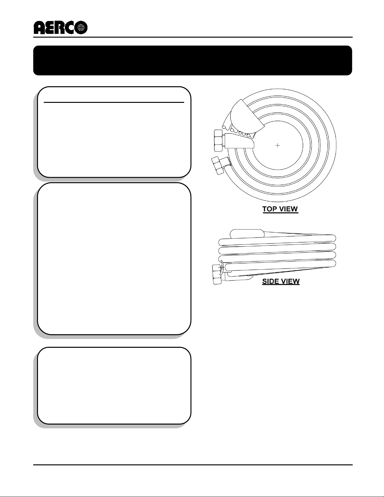
Coil Assembly in Water Heater Heat Exchanger
TECHNICAL INSTRUCTIONS
Coil and Riser
Replacement
Procedures for All Styles
of A, B, C, and D
Indirect-Fired Water
Indirect-Fire Water Heaters.
Description of Document:
This Technical Instruction Document
provides the instructions necessary for
AERCO Indirect-Fired Heat Exchangers.
These instructions must be performed
by a skilled service technician capable
of exercising the necessa
water systems.
The original document was formatted as
HE-109, but has now been changed
To a Technical Instruction Document
(TID-0004), to better conform to the new
an Application Guide,
document definitions.
Revised: 06/20/2011
NOTE
Page 2

Coil/Riser Replace Instructions for Helitherm Water Heaters
Technical instructions
Technical Support:
1-800-526-0288
www.aerco.com
HE-109
TID-0038_0A
(Mon–Fri, 8am-5pm EST)
Disclaimer
The information contained in this manual is subject to change without notice from AERCO International,
Inc. AERCO makes no warranty of any kind with respect to this material, including but not limited to
implied warranties of merchantability and fitness for a particular application. AERCO International is not
liable for errors appearing in this manual. Nor for incidental or consequential damages occurring in
connection with the furnishing, performance, or use of this material.
PR2: 04/01/11 Page 2 of 16
AERCO International, Inc. • 100 Oritani Dr. • Blauvelt, New York 10913 • Phone: 800-526-0288
Page 3
Coil/Riser Replace Instructions for Helitherm Water Heaters
Technical instructions
HE-104
SW1B-Plus Heat Exchanger Installation, Operation & Maintenance Instructions.
HE-110
B-Plus II Water Wizard Heat Exchanger Installation, Operation & Maintenance
VA-109
For removal of CXT-S 1” thru 2” Control Valve prior to hydrostatically testing and
VA-110
For removal of CXT-S 2.5” thru 4” Control Valve prior to hydrostatically testing
VA-106
For removal of CXT-P Control Valve prior to hydrostatically testing and for
AC-103
For adjusting Barber-Coleman Temperature Controller for re-commissioning unit.
HE-109
TID-0038_0A
1. Introduction
This document provides the instructions necessary for removal and replacement of Coil Assemblies and
Risers contained in AERCO Indirect-Fired Heat Exchangers. These instructions must be performed by a
skilled service technician capable of exercising the necessary safety precautions when working with high
temperature, pressurized steam and water systems. It is imperative that the following Safety Warnings
and Precautions be observed at all times:
2. Overview of Procedure
Installation, maintenance and operating personnel must, at all times observe all safety regulations. The
following warnings are general and must be given the same attention as specific precautions included in
these instructions.
FLUIDS UNDER PRESSURE MAY CAUSE INJURY TO PERSONNEL OR DAMAGE
TO EQUIPMENT WHEN RELEASED
Shut off all incoming and outgoing steam and water stop valves and carefully decrease
all trapped pressures to zero before performing any maintenance.
WARNING!
Never search for leakage in a live steam line by sight alone or by “feel”. Use a
Always provide yourself with personal protective equipment, (PPE) such as
LIVE STEAM CAN CAUSE SEVERE BURNS
mirror or other suitable polished object.
gloves, eye protection, dust mask, hard hat, etc.
WARNING!
3. Reference Documents
Refer to the following AERCO documents when removing, replacing or adjusting the indicated
components and assemblies:
HE-107
SW1A-Plus Heat Exchanger Installation, Operation & Maintenance Instructions.
Instructions.
for re-commisioning unit.
and for re-commisioning unit.
re-commissioning unit.
PR2: 04/01/11 Page 3 of 16
AERCO International, Inc. • 100 Oritani Dr. • Blauvelt, New York 10913 • Phone: 800-526-0288
Page 4
Coil/Riser Replace Instructions for Helitherm Water Heaters
Technical instructions
HE-109
TID-0038_0A
4. Tools and Equipment Required
The following common and special tools and equipment are required to perform the instructions contained
in this document:
Common Tools and Equipment
• Combination Wrenches: 7/16”, 5/8”,
13/16”, 1-1/16”, 1-1/8”
• Pipe Wrenches: 12” and 24”
• Chain Hoist
• Voltmeter:
• Brass Wire Brush
Special
Tools and Equipment
• Hydrostatic Pressure Pump: Range=
Up to 235 psig
• Torque Wrench, 75 ft.-lbs. With 1-1/4”,
1-5/16” & 1-1/2” Open-End Spanners
(1-1/4” Open-End Spanner required for
“A” Heater Only)
• Needle-Nose Pliers
• Gasket Removal Tool
• Carpenter’s Square
• Teflon Tape
• Orange Citric Cleaner
• Black Marker
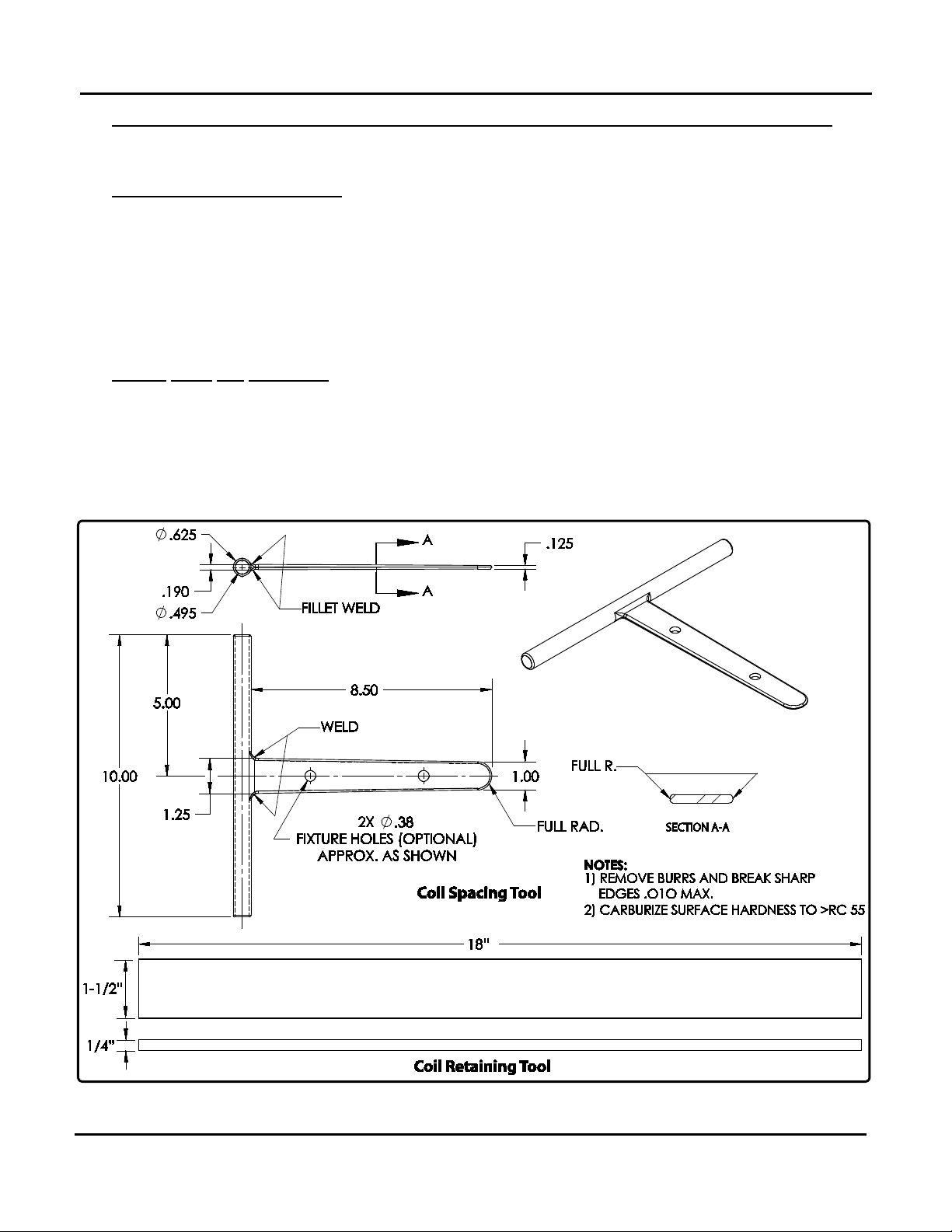
• Coil Retaining Tool (Figure 1)
• Coil Spacing Tool (Figure 1)
• Short-Length Wrenches: 1-1 /4”, 1-
5/16”, 1-1/2”
(Overall wrench lengths should be
approx. 6 inches or less)
Figure 1: Tool Fabrication Details: Coil Spacing and Retaining Tools
Recommended Material: 1018 steel
PR2: 04/01/11 Page 4 of 16
AERCO International, Inc. • 100 Oritani Dr. • Blauvelt, New York 10913 • Phone: 800-526-0288
Page 5
Coil/Riser Replace Instructions for Helitherm Water Heaters
Technical instructions
procedures should be performed in the order specified to minimize repair time.
Section 5.1 Instructions
END
HE-109
TID-0038_0A
5. Heater Isolation and Disassembly
The procedures in the following paragraphs are arranged to isolate, disconnect and
disassemble the unit to the extent necessary to repair or replace defective items. These
NOTE
5.1 Isolating Heater
To isolate the Heater from all facility energy sources (steam, water, electrical, etc.), proceed as follows:
1) Disconnect and Lock-Out/Tag-Out external AC power supplied to the Control Box and any other
devices connected to the Heater.
2) Using a voltmeter, check to ensure that all incoming voltage readings are zero Before
3) If the Heater is equipped with a Pneumatic Steam Valve, close the valve supplying air inlet
pressure to the Pneumatic Controller.
4) Close all stop valves in the Steam Inlet and Condensate Outlet lines
5) On the water-side, close the stop valves in the following order
6) Carefully open the Relief Valve located on the Top Head to relieve pressure in the Heater Shell.
7) While holding the Relief Valve open to prevent creating a vacuum in the Shell, open the Drain
• Hot water outlet line
• Recirculation line
• Cold water inlet line
Water should stop flowing from the valve within one minute. If water continues to flow from the
Relief Valve, one of the water stop valves is not securely closed.
Valve in the Bottom Head on the Heater. Completely drain the potable water from the Heater.
Isolating the Heater
continuing.
:
PR2: 04/01/11 Page 5 of 16
AERCO International, Inc. • 100 Oritani Dr. • Blauvelt, New York 10913 • Phone: 800-526-0288
Page 6

Coil/Riser Replace Instructions for Helitherm Water Heaters
Technical instructions
Using a 5/8” combination wrench, remove the Steam Pressure Line from the Steam Line and
Section 5.2 Instructions
END
5.2 Disconnecting Heater From the Facility
To disconnect the Heater from the facility piping and wiring connections, proceed as follows:
1) First, check the ceiling height to determine if the Heater Shell and Top Head can be hoisted up with
the Heater remaining in position.
2) If there is sufficient ceiling clearance to permit safe elevation of the Shell assembly, skip to step 8. If
there is insufficient clearance, proceed to step 3 to remove the Heater from its current location.
3)
Pressure Gauge.
4) Disconnect the Steam line from the Valve and Bottom Head.
5) Disconnect the water inlet from the Bottom Head.
6) Disconnect the drain line from the Bottom Head.
7) Disconnect the Condensate Drain piping from the Bottom Head.
8) Disconnect all electrical wires to the Control Box. Also, disconnect all wiring between the Control Box
and any external Solenoid Valve(s).
9) Using a 5/8” combination wrench, remove the Steam Pressure line from the Steam Line and Pressure
Gauge, if it was not performed in step 3.
10) Remove the water outlet piping from the Top Head.
11) Remove the pipe drain(s) from the Pressure Relief Valve(s).
12) Disconnect the pipe drain from the Water Solenoid Relief Valve.
13) Using a 13/16” combination wrench, disconnect the compression fittings on the Cold Water Feed
Tube from the Top Head and Bottom Head.
14) If controlled by a Pneumatic Valve, disconnect the incoming air supply to the Control Box and Steam
Valve.
15) If controlled by a Self-contained Valve, remove the thermal well from the Top Head that is attached to
the Valve.
Disconnecting the Heater from the Facility
HE-109
TID-0038_0A
PR2: 04/01/11 Page 6 of 16
AERCO International, Inc. • 100 Oritani Dr. • Blauvelt, New York 10913 • Phone: 800-526-0288
Page 7

Coil/Riser Replace Instructions for Helitherm Water Heaters
Technical instructions
Move the heat exchanger bundle a few feet to the side so that the Shell can be lowered to the floor.
Section 5.3 Instructions
END
Section 5.4 Instructions
END
Section 6.1 Instructions
END
5.3 Shell Removal
Remove the Heater Shell as follows:
HE-109
TID-0038_0A
1) Using a black marker, mark the edge of the Heater Bottom Head flange and Shell flange in order to
indicate their correct relative positions upon reassemble. The Top Head can remain attached to the
Shell.
2) Using the 1-1/16” combination wrench, unbolt the sixteen studs and nuts around the bottom ring of the
Shell. The two nuts located in-line with the mounting skid legs are to be removed with the stud left in
place.
3) Attach a chain hoist to the two lifting lugs on the Top Head. Lift the Shell up to clear the internal coil
bundle.
4) Using a light source, visually inspect the inside of the Heater Shell for evidence of damage to the
Copper Shell Liner. If any area of the Copper Liner is damaged, replace the Shell down on the Bottom
Head and contact your local AERCO Representative to process return of the Heater to AERCO for
repair.
Shell Removal
5)
Set the Shell on clean surface. Use care to avoid damaging the bottom edge of the Copper Shell Liner.
5.4 Removal of Coils and Risers
The Coil Assemblies, Riser and Condensate Return are removed as follows:
1) Using the proper size open-end wrench, loosen the two Union Nuts securing the Coils to the Steam
Riser and Condensate Return.
2) Using a pipe wrench, remove the Steam Riser and Condensate Return from the Bottom Head.
Removal of Coils and Risers
\
6. Assembly Preparation
Prior to reassembling Heater components, the Bottom Head, Steam Riser, Condensate Return and Coils
must be cleaned, inspected and prepared as described in the following paragraphs:
6.1 Preparation of Bottom Head
The Bottom Head of the Heater must be cleaned, inspected and prepared for reassembly as follows:
Preparation of Bottom Head
1) Clean off all debris from the topside of the Bottom Head.
2) Visually inspect the internal pipe threads where the Risers are connected. The overall depth of
threads should measure, (1-1/8” for 2” NPT and 1” for 1” NPT)
3) If the threads are less then the required depth, use the appropriate 1” or 2” NPT tap to clean out the
threads.
4) Using the gasket removal tool, remove the Shell Gasket from the Bottom Head. Use care to avoid
creating scratches or indents in the Bottom Head casting’s gasket surface area. Any linear scratches
can potentially create a leak.
5) Apply pipe dope to the internal NPT threads in the Bottom Head.
PR2: 04/01/11 Page 7 of 16
AERCO International, Inc. • 100 Oritani Dr. • Blauvelt, New York 10913 • Phone: 800-526-0288
Page 8

Coil/Riser Replace Instructions for Helitherm Water Heaters
Technical instructions
SPUD
THREADS
SEALING
SURFACE
STEAM RISER OR
CONDENSATE RETURN
SPUD
Section 6.2 Instructions
END
HE-109
TID-0038_0A
6.2 Preparation of Riser and Return
Preparation of Riser and Return
1) Visually inspect all Steam Riser and Condensate Return Spuds, (Figure 2) threads and sealing
surfaces for damage, scratches, braze material and cleaning deposits. If defects are found with the
Spud threads or sealing surfaces, contact your AERCO Representative for instruction to return the
defective Riser.
2) Using a brass wire brush, clean the threads of the Spuds. Use care to avoid scratching the sealing
surfaces of the Spuds. Scratches can cause a leak path under the Coil Gasket. After brush cleaning,
wipe with a clean lint-free cloth.
3) Using a brass wire brush, clean the pipe threads on the Riser. After cleaning, wipe with a clean lintfree cloth.
4) Wrap two layers of Teflon tape around the Riser NPT threads.
THE USE OF TEFLON TAPE OR ANY LUBRICANT ON THE THREADS OF THE SPUDS
IS PROHIBITED AND MAY VOID THE WARRANTY.
CAUTION!
Figure 2: Preparation of Riser/Return Spuds
PR2: 04/01/11 Page 8 of 16
AERCO International, Inc. • 100 Oritani Dr. • Blauvelt, New York 10913 • Phone: 800-526-0288
Page 9

Coil/Riser Replace Instructions for Helitherm Water Heaters
Technical instructions
SEE
DETAIL ‘A’
0
DETAIL ‘A’
TAILPIECE
SEATING
SURFACE
UNION
NUT
SEALING
SURFACE
BOX
HEADER
Visually inspect all Tail Piece sealing surfaces for cleanliness and evidence of damage.
Section 6.3 Instructions
END
HE-109
TID-0038_0A
6.3 Preparation of Coil Assemblies
1)
(Figure 3).
2) Pull the Union Nut forward against the seating surface of the Tail Piece and rotate the Union Nut
Preparation of Coil Assemblies
several turns to check for any obstructions around the perimeter of the seating surface. (Figure 3).
3) Contact your local AERCO Representative for replacement of the Coil if obstructions prohibit the
rotation of the Union Nut.
4) Using a brass wire brush, clean the internal threads of the Union Nut.
5) Using a citric orange cleaner, spray the area between the Union Nut and Tail Piece. While pulling the
Union Nut forward against the seating surface of the Tail Piece, rotate the Nut to remove any residue
that can cause unneeded friction between the two surfaces.
6) Form the Coil by creating a 1/8” minimum gap between the individual tubes and a 1/8” to 1/4” gap
between the four layers of tubes as shown in Figure 4. Maintain a flat surface on the top and bottom
tube surface of the Coil.
PR2: 04/01/11 Page 9 of 16
AERCO International, Inc. • 100 Oritani Dr. • Blauvelt, New York 10913 • Phone: 800-526-0288
Figure 3: Coil Assembly Preparation
Page 10

Coil/Riser Replace Instructions for Helitherm Water Heaters
Technical instructions
TOP VIEW
1/8" MINIMUM
1/8" TO 1/4"
1/8" TO 1/4"
SIDE VIEW
1/8" MINIMUM
Section 6.4 Instructions
END
HE-109
TID-0038_0A
Figure 4: Coil Assembly Spacing
6.4 Preparation of Coil Gaskets
Two 6-tab gaskets are provided with each replacement Coil Assembly. Proceed as follows:
1) Form the Gasket into a round shape
2) Using Needle-Nose Pliers, form the 6 tabs on each Coil Gasket by bending each tab outward 2 to 3
degrees as shown in Figure 5. This will secure the Gasket into the Spud’s inside diameter.
Preparation of Coil Gaskets
PR2: 04/01/11 Page 10 of 16
AERCO International, Inc. • 100 Oritani Dr. • Blauvelt, New York 10913 • Phone: 800-526-0288
Page 11

Coil/Riser Replace Instructions for Helitherm Water Heaters
Technical instructions
2 - 3°
Section 7.1 Instructions
END
HE-109
TID-0038_0A
Figure 5: Coil Gasket Preparation
7. Reassembly of Risers & Coil Bundle
Following preparation of all Heater components as described in Section 6, the Heater is ready for
reassembly as described in paragraphs 7.1 through 7.3.
7.1 Installing the Risers
1) Thread the Steam Riser into the Bottom Head.
2) Tighten the Riser until the center of the Spud is visually lined up to the cast notch on the Bottom Head.
3) Thread the Condensate Riser into the Bottom Head.
4) Tighten the Riser until the center of the Spud is visually lined up to the cast notch on the Bottom Head.
5) If this is a B+ II Water Wizard, thread the Sub-Cooling Coil onto the Condensate Riser, hand tight (ref.
paragraph 7.2). If this is not a B+ II Wizard Bundle assembly, proceed to step 9.
Installing the Risers
6) Measure the distance between the outside diameter of the Coil to the threaded stud protruding
through the Bottom Head on both sides of the Coil (Figure 6).
7) Position the Condensate Riser to create an equal distance between both measurements shown in
Figure 6.
8) Remove the Sub-Cooling Coil.
9) Thread a Steam Coil onto the Steam Riser, hand tight.
10) Position the Steam Riser so that the Condensate Tailpiece is aligned with the Spud on the
Condensate Riser.
11) Remove the Steam Coil.
12) Insert the properly formed Coil Gaskets into each Spud. Ensure that the Coil Gasket snaps into the
Spud (Fig. 7).
13) If the Coil Gasket is loose in the Spud, remove it and reform the six tabs to create a positive
connection into the Spud.
PR2: 04/01/11 Page 11 of 16
AERCO International, Inc. • 100 Oritani Dr. • Blauvelt, New York 10913 • Phone: 800-526-0288
Page 12

Coil/Riser Replace Instructions for Helitherm Water Heaters
Technical instructions
B*
A*
LOWER HEAD
SUB-COOLING
COIL
CONDENSATE
RISER
* MEASUREMENTS A & B SHOULD BE EQUAL
STUD
STUD
STEAM RISER OR
CONDENSATE RETURN
UNION NUT
COIL GASKET
BOX
HEADER
SPUD
HE-109
TID-0038_0A
Figure 6: Sub-Cooling Coil Alignment
Figure 7: Assembly of Coil to Steam Riser or Condensate Return
PR2: 04/01/11 Page 12 of 16
AERCO International, Inc. • 100 Oritani Dr. • Blauvelt, New York 10913 • Phone: 800-526-0288
Page 13

Coil/Riser Replace Instructions for Helitherm Water Heaters
Technical instructions
threads on the Riser Spuds.
Section 7.2 Instructions
END
Section 7.3 Instructions
END
The procedure in paragraph 7.2 are not required for Regular A, B, C or D Type Heaters.
NOTE
HE-109
TID-0038_0A
7.2 B+ II Wizard Sub-cooling Coil Installation
1) For Wizard Sub-cooling Coil, align the Union Nuts with the two Spuds on the Condensate Riser.
2) Hand thread the Unions Nuts down to the seating surface.
3) Position the Coil to a level position.
4) Using the 75 ft/lb torque wrench, tighten the Union Nuts.
5) If the Union Nuts do not seat properly, remove the Sub-cooling Coil and re-clean all surfaces and
B+ II Wizard Sub-cooling Coil Installation
7.3 Steam Coil Installation
1) While holding the Steam Coil horizontally with the Union Nuts facing the Riser Spuds, hand thread the
Steam Union Nuts onto the Spud. (Figure 7).
2) Hand thread the Condensate Union Nut onto the Spud.
3) Position the Coil horizontally.
4) Using a Carpenter’s Square, check the vertical alignment to ensure that the Coil is installed inside the
perimeter of the Shell. It is important that all coils in the bundle line up vertically and are positioned to
ensure that they will not rub against the Liner of the Heater Shell.
5) If needed, use the appropriate Short-Length wrench to tighten the Union Nuts to a seating condition.
6) Insert the Coil Retaining tool through the first lower section of the Coil tubing. (Figure 8).
7) Using a Torque Wrench set for 75 ft-lbs, insert the wrench in the proper torque direction on the Union
Nut (Figure 8).
8) Apply pressure to the Coil Retaining tool in the opposite direction of the pressure being applied to the
Torque Wrench and tighten the Union Nut.
9) When the Torque Wrench setting “clicks”, remove the Coil Retaining Tool.
10) Slowly reapply the pressure to the Torque Wrench holding the Coil by hand until the setting “clicks”. If
the Coil rotates during this operation, reinsert the Coil Retaining Tool and carefully apply a little more
torque.
11) Once again, reapply the pressure to the Torque Wrench without holding the Coil until the setting
“clicks”.
12) Repeat step 11 until the Torque Wrench setting “clicks” without rotating the Union Nut or twisting the
Coil.
13) Using the Coil Spacing Tool, perform a final spacing check of the Coil tubing by creating uniformed
gaps between the Coil tubes (see Figure 4). Check for spacing between the Box Header and Return
Bend. If the Return Bend is touching the Box Header, use the Coil Spacing Tool to separate the two
components. Check for spacing between the Coil tubes above and below the Box Header. Create
clearance using the Coil Spacing Tool.
14) Recheck all Union Nuts for the 75 ft/lbs setting without holding the Coil.
15) If a Union Nut or Coil rotates during this step, repeat steps 10 and 11.
Steam Coil Installation
PR2: 04/01/11 Page 13 of 16
AERCO International, Inc. • 100 Oritani Dr. • Blauvelt, New York 10913 • Phone: 800-526-0288
Page 14

Coil/Riser Replace Instructions for Helitherm Water Heaters
Technical instructions
COIL RETAINING
TOOL
BOX HEADER
RISER
UNION
NUT
INSERT COIL RETAINING
TOOL HERE
BOX
HEADER
RISER
TOP VIEW (PARTIAL CUT-AWAY)
SIDE VIEW
COIL
ASSEMBLY
COIL
ASSEMBLY
HE-109
TID-0038_0A
Figure 8: Positioning of Coil Retaining Tool
PR2: 04/01/11 Page 14 of 16
AERCO International, Inc. • 100 Oritani Dr. • Blauvelt, New York 10913 • Phone: 800-526-0288
Page 15

Coil/Riser Replace Instructions for Helitherm Water Heaters
Technical instructions
Section 8. Instructions
END
the failed Coil.
Section 9. Instructions
END
HE-109
TID-0038_0A
8. Hydrostatically Testing Coils & Risers
1) Install fittings into the inlet and outlet of the Bottom for the Risers that can supply a hydrostatic
pressure source.
2) One fitting should have a valve for the release of internal air pressure.
3) The other fitting should be attached to a source to apply the maximum allowable working pressure,
(MAWP) to the internal Coil and Riser Bundle.
4) Apply MAWP to the Coil Bundle.
5) Close off both inlet and outlet valves to retain the internal pressure for 20 minutes.
6) If leaks are detected, remove the internal pressure.
7) Remove the leaking Coil and inspect for causes for leak.
8) If the leak is due to debris, clean the Coil and reinstall.
9) If there are damages to any surfaces, contact your AERCO Representative for instruction for returning
the failed Coil.
Hydrostatically Testing Coils & Risers
9. Reassembly of Shell
1) Install fittings into the inlet and outlet of the Bottom for the Risers that can supply a hydrostatic
pressure source.
2) One fitting should have a valve for the release of internal air pressure.
3) The other fitting should be attached to a source to apply the maximum allowable working pressure,
(MAWP) to the internal Coil and Riser Bundle.
4) Apply MAWP to the Coil Bundle.
5) Close off both inlet and outlet valves to retain the internal pressure for 20 minutes.
6) If leaks are detected, remove the internal pressure.
7) Remove the leaking Coil and inspect for causes for leak.
8) If the leak is due to debris, clean the Coil and reinstall.
9) If there are damages to any surfaces, contact your AERCO Representative for instruction for returning
Reassembly of Shell
10. Reinstalling Heater in Facility
Reassemble all components that were disconnected in paragraph 5.2. When re-installing the Thermal
Element into the Thermal Well Bushing in the Top Head, be careful not to damage the Element against
the internal Coils. Straighten the Element before inserting.
11. Startup Procedure
Follow the Operating Procedures in the appropriate O & M Manual listed in paragraph 3 (Reference
Documents).
PR2: 04/01/11 Page 15 of 16
AERCO International, Inc. • 100 Oritani Dr. • Blauvelt, New York 10913 • Phone: 800-526-0288
Page 16

Coil/Riser Replace Instructions for Helitherm Water Heaters
Technical instructions
HE-109
TID-0038_0A
© AERCO International, Inc., 2011
PR2: 04/01/11 Page 16 of 16
AERCO International, Inc. • 100 Oritani Dr. • Blauvelt, New York 10913 • Phone: 800-526-0288
 Loading...