

Page 1

structio In n
AERCO INTERNATIONAL, Inc., Northvale, New Jersey, 07647 USA
No.
GF-112
C-MORE CONTROL PANEL
OPERATION
For
Benchmark Series
&
KC Series
Systems
Printed in U.S.A. REVISED JANUARY, 2009
Page 2

Page 3

C-MORE CONTROL PANEL OPERATION
TABLE OF CONTENTS
PARA. PAGE
SECTION 1 – GENERAL INFORMATION 1
1.1 INTRODUCTION 1
1.2 SAFETY PRECAUTIONS AND WARNINGS 1
1.3 FEATURES AND BENEFITS 1
1.4 CONTROL PANEL DESCRIPTION 2
SECTION 2 – CONTROL PANEL MENU STRUCTURE 6
2.1 CONTROL PANEL MENUS 6
2.2 MENU PROCESSING PROCEDURES 6
2.3 OPERATING MENU 7
2.4 SETUP MENU 7
2.5 CONFIGURATION MENU 8
2.6 TUNING MENU 10
2.7 CALIBRATION MENU 11
2.8 DIAGNOSTICS MENU 11
SECTION 3 – CONTROL PANEL MENU DESCRIPTIONS 13
3.1 MENU ITEM DESCRIPTIONS 13
3.2 FACTORY DEFAULTS 13
SECTION 4 – CONTROL PANEL DISPLAY MESSAGES 21
4.1 STARTUP AND STATUS MESSAGES 21
4.2 FAULT MESSAGES 21
SECTION 5 –INPUT/OUTPUT INTERFACES & OPERATING MODES 24
5.1 INTRODUCTION 24
5.2 I/O INTERFACES 24
5.3 MODES OF OPERATION 26
5.4 START SEQUENCE 31
i
Page 4

C-MORE CONTROL PANEL OPERATION
TABLE OF CONTENTS - Continued
SECTION 6 – CALIBRATION AND DIAGNOSTIC MENUS 33
6.1 INTRODUCTION 33
6.2 CALIBRATION PROCEDURES 33
6.3 DIAGNOSTICS PROCEDURES 35
SECTION 7 – RS232 COMMUNICATION 38
7.1 INTRODUCTION 38
7.2 RS232 COMMUNICATION SETUP 38
7.3 MENU PROCESSING UTILIZING RS232
COMMUNICATION
7.4 DATA LOGGING 39
APPENDIX A - C-MORE CONTROL PANEL VIEWS A-1
APPENDIX B - TROUBLESHOOTING GUIDE B-1
APPENDIX C - INDOOR/OUTDOOR RESET RATIO CHARTS C-1
APPENDIX D - TEMPERATURE SENSOR RESISTANCE CHART D-1
APPENDIX E - WIRING DIAGRAMS E-1
APPENDIX F - C-MORE CONTROL PANEL DIP SWITCH
SETTINGS
38
F-1
ii
Page 5

C-MORE CONTROL PANEL OPERATION
SECTION 1 - GENERAL INFORMATION
1.1 INTRODUCTION
The information in this Section provides a guide
to the operation of KC and Benchmark Series
units using the C-More Control Panel. In
addition, it provides information describing the
numerous types of external sensors and control
devices which can be interfaced to the unit using
terminals provided in the Input/Output (I/O) Box
utilized with the Control Panel. Information
regarding the set up of all Water Heater and
Boiler Operating Modes is also included herein.
1.2 SAFETY PRECAUTIONS AND WARNINGS
It is imperative that the initial startup of KC and
Benchmark Series units be performed by factory
trained personnel. Operation prior to initial
startup by factory trained personnel will void the
equipment warranty. In addition, the following
WARNINGS and CAUTIONS must be observed
at all times.
CAUTION:
All initial installation procedures must be
satisfied before attempting to start the unit.
WARNING:
ELECTRICAL VOLTAGES IN KC SERIES
UNITS INCLUDE 120 AND 24 VOLTS AC.
VOLTAGES IN BENCHMARK SERIES UNITS
MAY ALSO INCLUDE 460 AND 220 VOLTS
AC. THEREFORE, THESE UNITS MUST BE
SERVICED ONLY BY FACTORY CERTIFIED
SERVICE TECHNICIANS.
WARNING:
DO NOT ATTEMPT TO DRY FIRE THE
UNIT. STARTING THE UNIT WITHOUT A
FULL WATER LEVEL CAN SERIOUSLY
DAMAGE THE UNIT AND MAY RESULT IN
PERSONNEL INJURY OR PROPERTY
DAMAGE. THIS SITUATION WILL VOID ANY
WARRANTY.
FEATURES AND BENEFITS
KC and Benchmark Series units equipped
the new C-More Control Panel include a number
of additional features and benefits. These
include:
1.3.1 System Start Temperature
The Sy tem Start Temperature feature s allows a
boiler to be enabled or disabled based on the
outside air temperature. When the outside air
temperature goes below the System Start
Temperature, the boiler is enabled. When the
outside air temperature is above the System
Start Temperature, the boiler is disabled. This
feature may be used in any boiler mode of
operation. It requires that an outdoor air
temperature sensor be connected to the boiler.
1.3.2 Setpoint Low Limit
This option allows the user to
unit’s setpoint can be set. The allowable range is
40°F to 240°F. The factory default is set at 60°F.
limit how low the
1.3.3 Setpoint High Limit
This option has two functions. In the
Indoor/Outdoor Reset, Constant Setpoint and 4
to 20 mA Remote Setpoint Modes, the Setpoint
High Limit option limits how high the unit’s
setpoint can be set. The allowable range is 40°F
to 240°F.
In the 4 to 20 mA Direct Drive, Combination or
BMS Mode of operation, the Setpoint High Limit
acts as a temperature limiting governor. Should
the unit’s outlet temperature equal the Setpoint
High Limit Setting, a PID function will intervene
and maintain the outlet temperature at the
Setpoint High Limit minus the Setpoint Limit
Band.
To use the Setpoint High Limit feature, the
Setpoint Limiting option must be enabled and a
Setpoint Limit Band selected. This Band is
preset at 5°F, however it is adjustable from 0°F
to 10°F.
1.3.4
with
1.3
1
Page 6

C-MORE CONTROL PANEL OPERATION
Temp Hi Limit
The Temp Hi Limit is a te e The F
that will shut down the unit and generate an
alarm if the if the outlet temperature exceeds its
setting. It is preset at 210°F, however it is
adjustable from 40°F to 240°F.
mperature limit featur
1.3.5 Max Fire Rate
This feature allows the
firing rate. This feature can be useful if site or
equipment limitations require that less BTU’s be
input into the system. This feature is meant to be
used only on a temporary basis until the system
or equipment limitations are resolved.
user to limit the unit’s
1.3.6 Pump Delay Timer
The C-More control system a
turn a pump on and off as the boiler cycles on
and off on demand. The Pump Delay Timer
feature allows the user to keep the pump
running up to 30 minutes after the unit has shut
down and the demand satisfied.
llows the user to
1.3.7 Aux Start On Delay
The AUX START ON DELAY
conjunction with the Auxiliary Relay. When a call
for heat is produced, the Aux Relay will energize
and can be used to start a system or gas
booster pump, open a louver or valve, or start
some other necessary system process. The Aux
Start On Delay is a timer that can be set from 0
to 120 seconds. It tells the combustion control
system to wait a specified period of time for the
device started by the Aux Relay to come up to
speed, open or make a proving switch. Once the
waiting period expires, the start sequence will
resume. Should the device not prove within the
preset time interval, the unit will shut down and
generate an alarm.
feature works in
1.3.8
Failsafe Mode
whether the unit shuts down or switches to the
Constant Setpoint mode of operation in the
event that a loss of signal causes the unit to
become inoperable. For example, if a 4 to 20
mA Remote Setpoint signal is being sent, but is
not seen by the unit, the unit will shut down or
automatically switch to the Constant Setpoint
mode and work off the unit’s internal setpoint.
The default setting for this option is Shutdown.
1.3.9 RS232 Monitoring
This feature allows a laptop co
suitable device to be connected to the RS232
port on the Control Panel front panel. This
permits the unit to be monitored either locally or
remotely via a Modem.
1.3.10 Aux Temp
This feature permits a
connected to the Aux Sensor In terminals in the
I/O Box. The sensor must be within the
resistance range used with the C-More Control
system. It can be used to monitor the user’s
parameter of choice. This feature is always
enabled. This is strictly a monitoring function
and plays no role in control of the unit.
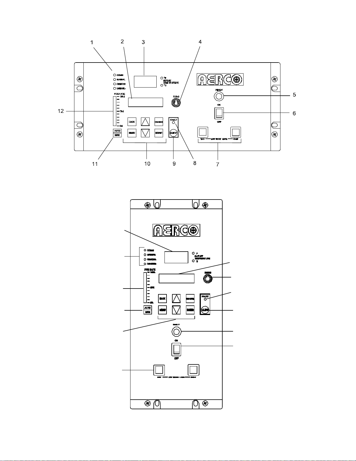
1.4 CONTROL PANEL DESCRIPTION
The C-More Control Panel is available in t
models. One model has a horizontal panel
control layout as shown in Figure 1-1A and is
used on KC Series units. The other model has a
vertical panel control layout as shown in Figure
1-1B and is used on Benchmark Series units.
These models contain identical controls,
indicators and displays and are functionally
identical. These controls, indicators and displays
are listed and described in Table 1-1.
ailsafe mode allows
temperature sensor to be
the user to select
mputer or other
wo
2
Page 7
C-MORE CONTROL PANEL OPERATION
Figure 1-1A. C-More Control Panel For KC Series Units
12
10
7
11
3
1
2
4
8
9
5
6
Figure 1-1B. C-More Control Panel For Benchmark Series Units
3
Page 8

C-MORE CONTROL PANEL OPERATION
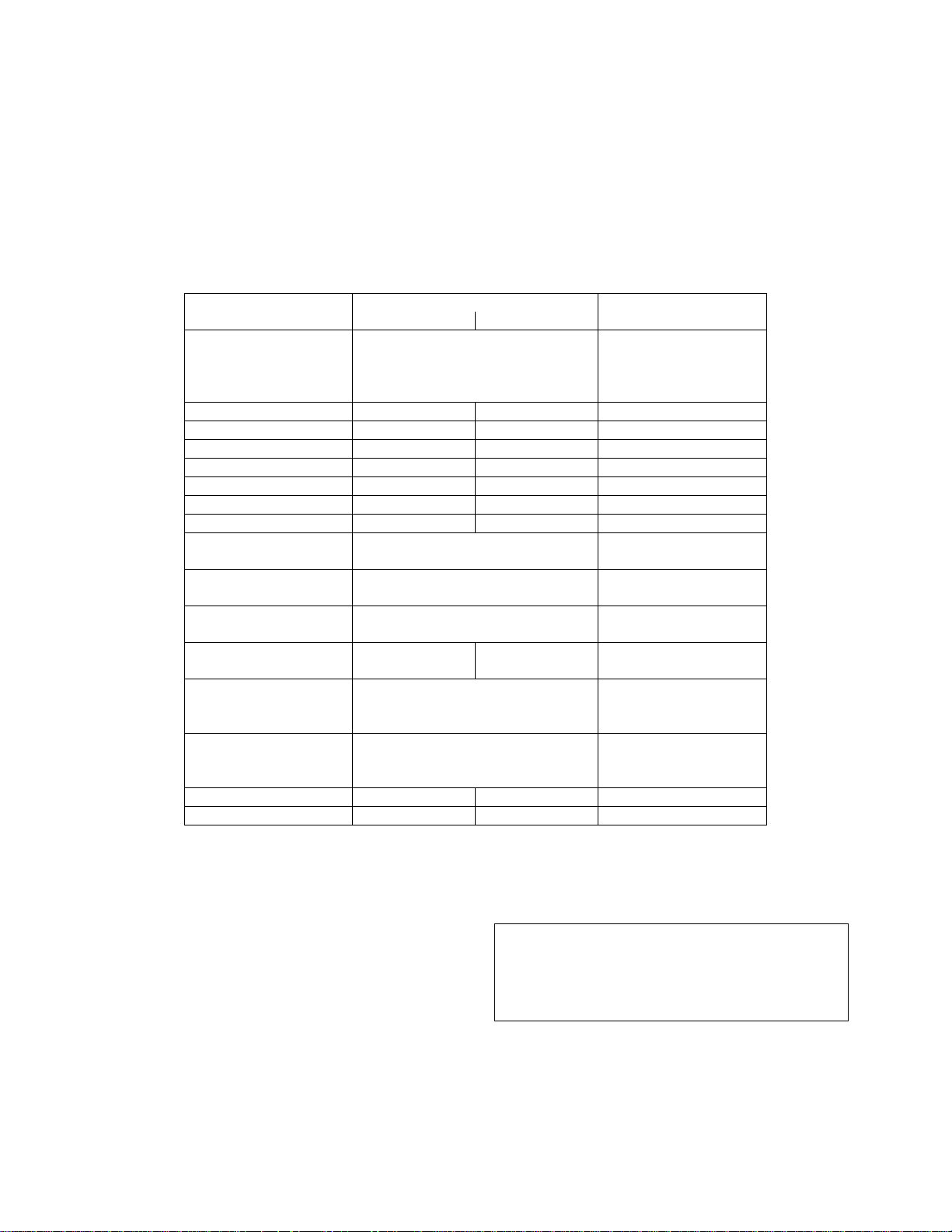
Table 1-1. Operating Controls, Indicators and Displays
ITEM
NO.
CONTROL, INDICATOR
OR DISPLAY
1 LED Status Indicators Four Status LEDs indicate the current operating status as
follows:
COMM
MANUAL
REMOTE
DEMAND
2 VFD Display Vacuum Fluorescent Display (VFD) consists of 2 lines each
OUTLET
3
TEMPERATURE
Display
RS232 Port
4
READY Indicator
5
ON/OFF Switch
6
LOW WATER LEVEL
7
TEST/RESET Switches
FAULT Indicator Red FAULT LED indicator lights when a boiler alarm
8
CLEAR Key
9
10 MENU Keypad Consists of 6 keys which provide the following functions for
MENU
BACK
Lights when RS232 communication is occurring
Lights when the unit is being controlled using the front panel
keypad.
Lights when the unit is being controlled by an external signal
from an Energy Management System
Lights when there is a demand for heat.
capable of displaying up to 16 alphanumeric characters. The
information displayed includes:
Startup Messages
Alarm Messages
Operating Status Messages
Menu Selections
3–Digit, 7–Segment LED display continuously displays the
outlet water temperature. The °F or °C LED next to the
display lights to indicate whether the displayed temperature is
in degrees Fahrenheit or degrees Celsius.
Port permits a Laptop Computer or External Modem to be
connected to the unit’s Control Panel.
Lights when ON/OFF switch is set to ON and all Pre-Purge
conditions have been satisified.
Enables and disables boiler operation.
Allow the operator to test the operation of the water level
monitor.
Pressing TEST opens the water level probe circuit and
simulates a Low Water Level alarm.
Pressing RESET resets the water level monitor circuit.
Pressing CLEAR resets the display.
condition occurs. An alarm message will appear in the VFD.
Turns off the FAULT indicator and clears the alarm message
if the alarm is no longer valid. Lockout type alarms will be
latched and cannot be cleared by simply pressing this key.
Troubleshooting may be required to clear these types of
alarms
the Control Panel Menus:
Steps through the main menu categories shown in Figure 2-1.
The Menu categories wrap around in the order shown.
Allows you to go back to the previous menu level without
changing any information. Continuously pressing this key will
bring you back to the default status display in the VFD. Also,
this key allows you to go back to the top of a main menu
category.
FUNCTION
4
Page 9

ITEM
NO.
10
(Cont.)
C-MORE CONTROL PANEL OPERATION
Table 1-1. Operating Controls, Indicators and Displays - Continued
CONTROL, INDICATOR
OR DISPLAY
▲ (Up) Arrow When in one of the main menu categories (Figure 1-2),
pressing this key will select the displayed menu category. If
the CHANGE key was pressed and the menu item is flashing,
pressing the ▲ arrow key will increment the selected setting.
▼ (Down) Arrow When in one of the main menu categories (Figure 1-2),
pressing this key will select the displayed menu category. If
the CHANGE key was pressed and the menu item is flashing,
pressing the ▼ (Down) arrow key will increment the selected
setting.
FUNCTION
CHANGE
ENTER
11
12
AUTO/MAN Switch
FIRE RATE Bargraph
Permits a setting to be changed (edited). A valid password
must be entered before changing most menu items. When
the CHANGE key is pressed, the displayed menu item will
begin to flash. Pressing the ▲ or ▼ arrow key when the item
is flashing will increment or decrement the displayed setting.
Saves the modified menu information in memory. The
display will stop flashing.
This switch toggles the boiler between the Automatic and
Manual modes of operation. When in the Manual (MAN)
mode, the front panel controls are enabled and the MANUAL
status LED lights.
When in the Automatic (AUTO) mode, the MANUAL status
LED will be off and the front panel controls disabled.
20 segment red LED bargraph continuously shows the Fire
Rate in 5% increments from 0 to 100%
5
Page 10
C-MORE CONTROL PANEL OPERATION
SECTION 2 - CONTROL PANEL MENU STRUCTURE
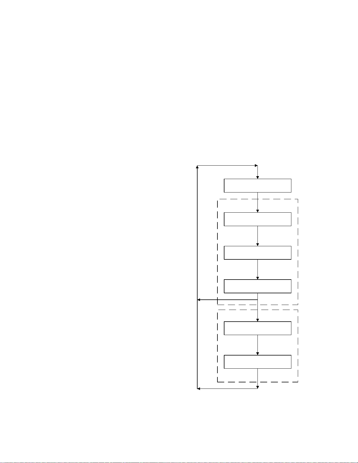
2.1 CONTROL PANEL MENUS
The Control Panel incorporates an extensive
menu structure which permits the operator to set
up, and configure the unit. The menu structure
consists of six major menu categories as shown
in Figure 2-1. Each of the menus shown, contain
options which permit operating parameters to be
viewed or changed. The menus are protected by
two different password levels to prevent
unauthorized use.
Password Level 1 allows viewing of all menu
categories and also allows the Setup,
Configuration and Tuning Menu options to be
changed.
Password Level 2 allows viewing and changing
of all Level 1 menu categories and also allows
access to the Calibration and Diagnostic Menus.
These two additional menu categories should
only be used by factory trained personnel to
calibrate and troubleshoot the unit.
A third Password Level called the Factory
Password also exists. However, access to this
menu is restricted to Factory Authorized
personnel only.
Prior to entering the correct password, the
options contained in the Operating, Setup,
Configuration and Tuning Menu categories can
be viewed. However, except for Internal Setpoint
Temperature (Configuration Menu), none of the
viewable menu options can be changed.
Once the valid Level 1 (159) or Level 2 (6817)
password is entered, the options listed in the
available menus can be viewed and changed, if
desired.
2. Press the MENU key. The display will show
the Setup Menu which is the next menu
category shown in Figure 2-1. This menu
contains the Password option which must be
entered if other menu options will be
changed.
3. Continue pressing the MENU key until the
desired menu is displayed.
4. With the desired menu displayed, press the
▲ or ▼ arrow key. The first option in the
selected menu will be displayed.
OPERATING
LEVEL 1 PWD
SETUP
CONFIGURATION
TUNING
LEVEL 2 PWD
CALIBRATION
2.2 MENU PROCESSING PROCEDURE
Accessing each menu and option is
accomplished using the Menu Keys shown in
Figure 1-1. Therefore, it is imperative that you
be thoroughly familiar with the following basic
steps before attempting to perform specific
menu processing procedures.
1. The Control Panel will normally be in the
Operating Menu and the VFD will display the
current unit status. Pressing the ▲ or ▼
arrow key will display the other available data
in the Operating Menu.
6
DIAGNOSTICS
Figure 2-1. Menu Structure
Page 11

C-MORE CONTROL PANEL OPERATION
5. Continue pressing the ▲or ▼ arrow key until
the desired menu option is displayed.
Pressing the ▲ arrow key will display the
available menu options in the Top-Down
sequence. Pressing the ▼ arrow key will
display the options in the Bottom-Up
sequence. The menu options will wraparound after the first or last available option.
6. To change the value or setting of a displayed
menu option, press the CHANGE key. The
displayed option will begin to flash. Press the
▲ or ▼ arrow key to scroll through the
available menu option choices for the option
to be changed. The menu option choices do
not wrap around.
7. To select and store a changed menu option,
press the ENTER key.
NOTE:
Paragraphs 2.3 through 2.8 provide brief
descriptions of the options contained in
each menu. Refer to Section 3 for detailed
descriptions of each menu option.
2.3 OPERATING MENU
The Operating Menu displays the unit status and
a number of key operating parameters for the
unit as listed in Table 2-1. This menu is “ReadOnly” and does not allow personnel to change or
adjust any of the displayed items. Since this
menu is “Read-Only”, it can be viewed at any
time without entering a password. Press the ▲
arrow key to display the menu item in the order
listed (Top-Down). Pressing the ▼ arrow key
will display the menu items in reverse order
(Bottom-Up).
2.4 SETUP MENU
The Setup Menu (Table 2-2) permits the
operator to set the unit password which is
required to change any of the menu options. To
prevent unauthorized use, a previously entered
password entry will time-out after 1 hour.
Therefore, the password must be reentered
when required. In addition to permitting
password entries, the Setup Menu is also used
to enter date and time, language to be used for
display messages, units of temperature
measurements and entries required for external
communication and control of the unit via the
RS232 port. A view-only software version
display is also provided to indicate the current
Control Box software version,
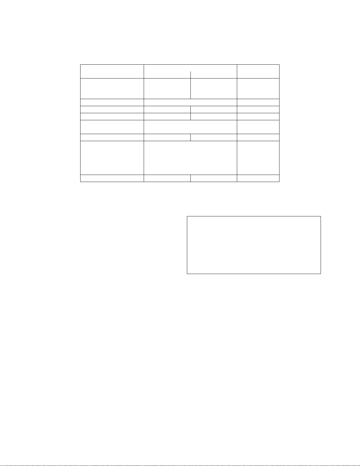
NOTE
The Outdoor Temp display item shown with an asterisk in Table
2-1 will not be displayed unless the Outdoor Sensor function has
been enabled in the Configuration Menu (Table 2-3).
Table 2-1. Operating Menu
Available Choices or Limits
Menu Item Display Minimum Maximum Default
Status Message
Active Setpoint 40°F 240°F
Aux Temp 30°F 245°F
Outdoor Temp* -70°F 130°F
Fire Rate In 0% Max Fire Rate
Flame Strength 0% 100%
Run Cycles 0 999,999
Run Hours 0 999,999
Fault Log 0 9 0
7
Page 12
C-MORE CONTROL PANEL OPERATION
Table 2-2. Setup Menu
Available Choices or Limits
Menu Item Display Minimum Maximum Default
Passsword
Level 1 = 159
Level 2 = 6817
Language English English
Time 12:00 am 11:59 pm
Date 01/01/00 12/31/99
Unit of Temp Fahrenheit
Comm Address 0 127 0
Baud Rate 2400
Software Ver 0.0 Ver 9.9
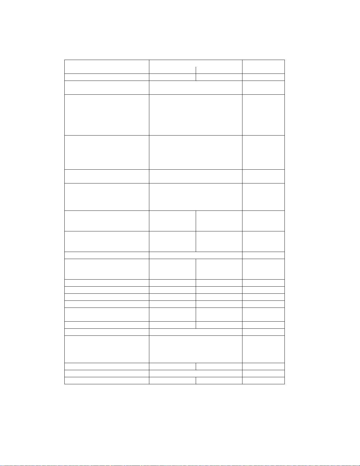
2.5 CONFIGURATION MENU
The Configuration Menu shown in Table 2-3
permits adjustment of the Internal Setpoint
(Setpt) temperature regardless of whether the
valid password has been entered. Setpt is
required for operation in the Constant Setpoint
mode. The remaining options in this menu
require the valid password to be entered, prior to
changing existing entries. This menu contains a
number of other configuration settings which
may or may not be displayed, depending on the
current operating mode setting.
0 9999 0
Celsius
4800
9600
19.2K
The Configuration Menu settings shown in
Table 2-3 are Factory-Set in accordance
with the requirements specified for each
individual order. Therefore, under normal
operating conditions, no changes will be
required.
Fahrenheit
9600
NOTE:
8
Page 13
C-MORE CONTROL PANEL OPERATION
Table 2-3. Configuration Menu
Available Choices or Limits
Menu Item Display Minimum Maximum Default
Internal Setpt Lo Temp Limit Hi Temp Limit 130°F
Unit Type Boiler
Unit Size 0.5 MBTU
Boiler Mode
(If Unit Type = Boiler)
Heater Mode
(If Unit Type = Water Heater)
Remote Signal
(If Mode = Remote Setpoint,
Direct Drive or Combination)
Bldg Ref Temp
(If Boiler Mode = Outdoor
Reset)
Reset Ratio
(If Boiler Mode = Outdoor
Reset)
Outdoor Sensor Enabled or Disabled Disabled
System Start Tmp
(If Outdoor Sensor =
Enabled)
Setpt Lo Limit 40°F Setpt Hi Limit 60°F
Setpt Hi Limit Setpt Lo Limit 240°F 200°F
Temp Hi Limit 40°F 240°F 210°F
Max Fire Rate 40% 100% 100%
Pump Delay Timer
(If Unit Type = Boiler)
Aux Start On Dly 0 sec 120 sec 0 sec
Failsafe Mode Shutdown or Constant Setpt Shutdown
mA Output Setpoint
Low Fire Timer 2 sec 120 sec 2 sec
Setpt Limiting Enabled or Disabled Disabled
Setpt Limit Band 0°F 10°F 5°F
Boiler
Water Heater
1.0 MBTU
1.0 MBTU
1.5 MBTU
2.0 MBTU
2.5 MBTU
3.0 MBTU
Constant Setpoint
Remote Setpoint
Direct Drive
Combination
Outdoor Reset
Constant Setpoint
Remote Setpoint
4 – 20 mA/1 – 5V
0 -20 mA/0 – 5V
PWM Input (BMS)
Network
40°F 230°F 70°F
0.1 9.9 1.2
30°F 100°F 60°F
0 min 30 min 0 min
Outlet Temp
Fire Rate Out
Off
Constant
Setpoint
Constant
Setpoint
4 to 20 mA/
1-5V
Off
9
Page 14

C-MORE CONTROL PANEL OPERATION
2.6 TUNING MENU
The Tuning Menu items in Table 2-4 are Factory
set for each individual unit. Do not change
these menu entries unless specifically requested
to do so by Factory-Trained personnel.
The Breakpoint Menu items shown in the following
Table with an asterisk are displayed only if Unit
Type = Water Heater and the Heatr Bkpt Dsp
option in the Calibration Menu (Table 2-5) is
Enabled. These Breakpoint values correspond to a
130°F default setpoint
Table 2-4. Tuning Menu
Available Choices or Limits
Menu Item Display Minimum Maximum Default
Prop Band 1°F 120°F 70°F (Boiler)
Integral Gain 0.00 2.00 1.00 (Boiler)
Derivative Time
(If Unit Type = Boiler)
Min Load Adj
(If Unit Type = Water Heater)
Max Load Adj
(If Unit Type = Water Heater)
FFWD Temp
(If Unit Type = Water Heater)
Outlet Feedback
(If Unit Type = Water Heater)
Feedback Gain
(If Unit Type = Water Heater
& Heatr Tuning Dsp is
Enabled)
Breakpt at 100%* 30°F 240°F 77°F
Breakpt at 90%* 30°F 240°F 81°F
Breakpt at 80%* 30°F 240°F 85°F
Breakpt at 70%* 30°F 240°F 91°F
Breakpt at 60%* 30°F 240°F 95F
Breakpt at 50%* 30°F 240°F 102F
Breakpt at 40%* 30°F 240°F 110°F
Breakpt at 30%* 30°F 240°F 112°F
Breakpt at 20%* 30°F 240°F 114°F
Breakpt at 10%* 30°F 240°F 130°F
Breakpt at 0%* 30°F 240°F 135°F
Reset Defaults? Yes
0.00 min 2.00 min 0.00 min (Boiler)
-50°F 50°F 0°F
-50°F 50°F 0°F
30°F 245°F
.01 1.00 0.05
Are You Sure?
NOTE
On (Yes)
Off (No)
No
8°F (Water Heater)
1.60 (Water Heater)
0.10 min (Water Heater)
On (Yes)
No
10
Page 15
C-MORE CONTROL PANEL OPERATION
2.7 CALIBRATION MENU
The Calibration Menu is used by Factory
Trained Service personnel to adjust or reset the
parameters listed in Table 2-5.
Table 2-5. Calibration Menu
Available Choices or Limits
Menu Item Display Minimum Maximum Default
Stepper Fbk
(Not adjustable via
RS232 serial
communication)
PWM In Adj -5.0% 5.0% 0.0%
Analog In Adj -5.0% 5.0% 0.0%
Flow In Adj -5.0% 5.0% 0.0%
CO In Adj -5.0% 5.0% 0.0%
O2 In Adj -5.0% 5.0% 0.0%
mA Out Adj -1.0 mA 1.0 mA 0.0 mA
A/F Sensitivity 1% 5% 2%
Power Reset Automatic
Water Temp Reset Automatic
Gas Press Reset Automatic
Min Off Time 0 Min 15 Min 1 Min (Boiler)
Heatr Tuning Dsp
(If Unit Type = Water
Heater)
Heatr Bkpt Dsp
(If Unit Type = Water
Heater)
Stop Level 0% Start Level 16
Start Level Stop Level 40% 20
Cal 100%
Verify 50%
Enabled or Disabled Disabled
Enabled or Disabled Disabled
Cal 0%
Manual
Manual
Manual
Cal 0%
Automatic
Automatic
Manual
0 Min (Water Heater)
2.8 DIAGNOSTICS MENU
The Diagnostics Menu shown in Table 2-6 is
used by Factory-Trained Service personnel to
troubleshoot the unit. This menu category
contains a number of Built In Test (BIT) test
routines to be used to check the operational
status of the Control Panel displays and keypad
keys. It also allows the operator to activate
relays, view switch status and increment the
stepper motor contained in the Air/Fuel Valve.
NOTE
With the exception of the Sensor Log Interval
(Int) setting, none of the following Diagnostic
Menu items can be initiated via a remote serial
communications link.
11
Page 16

C-MORE CONTROL PANEL OPERATION
Table 2-6. Diagnostics Menu
Available Choices or Limits
Menu Item Display Minimum Maximum Default
Display Test Off
LEDs
7-Seg
Bar-graph
Keypad Test Off
Manual, Menu
Up, Down
Change, Enter
Clear
(Back Key exits test mode)
Relay Test
(Allows user to force
outputs ON or OFF)
Switch Test
(Allows user to view
the status of all
switch inputs)
Stepper Test
(Allows user to
adjust the stepper
motor position using
the ▲ and ▼ keys)
Sensor Log Int
(Allows user to set
the time interval for
logging Sensor
inputs in Database)
Igniter ON/Igniter OFF
Blower ON/Blower OFF
Pump ON/Pump OFF
Aux ON/Aux OFF
Fault ON/Fault OFF
Exhaust sw ON/Exhaust sw OFF
SSOV sw ON/SSOV sw OFF
Blower Proof ON/Blower Proof OFF
Ignition sw ON/Ignition sw OFF
Over Temp sw ON/Over Temp sw OFF
Low Gas Pres ON/Low Gas Pres OFF
Hi Gas Pres ON/Hi Gas Pres OFF
Water Lev sw ON/Water Lev sw OFF
Rem Int sw ON/Rem Int sw OFF
Front Pnl sw ON/Front Pnl sw OFF
Delayed Int ON/Delayed Int OFF
Purge sw ON/Purge sw OFF
0% 100% 0%
12 Hrs, or 24 Hrs
Off
Off
Off
1 Min, 5 Min
15 Min, 30 Min
1 Hr, 6 Hrs
Off
Off
Off
Off
30 Min.
12
Page 17

C-MORE CONTROL PANEL OPERATION
SECTION 3 - CONTROL PANEL MENU DESCRIPTIONS
3.1 MENU ITEM DESCRIPTIONS
Descriptions of the menu items and options
contained in each of the six major menu
categories are listed and described in Table 3-1.
Factory Default values for each of these items
are summarized in Table 3-2.
3.2 FACTORY DEFAULTS
The factory default values for each menu item
are summarized in Table 3-2.
Table 3-1. Menu Item Descriptions
MENU LEVEL & OPTION DESCRIPTION
OPERATING MENU
Active Setpoint This is the setpoint temperature to which the control
is operating when operating in the Constant Setpoint,
Remote Setpoint or Outdoor Reset (Boiler Only)
Mode. When in the Constant Setpoint Mode, this
value is equal to the Internal Setpoint setting in the
Configuration Menu. When in the Remote Setpoint
Mode, this value is the setpoint equivalent to the
remote analog signal supplied to the unit. When
operating a Boiler in the Outdoor Reset Mode, this is
the derived value from the charts in Appendix C.
Aux Temp For monitoring purposes only
Outdoor Temp Displayed only if outdoor sensor is installed and
enabled.
Fire Rate In Desired input fire rate. This would normally be the
same as the fire rate shown on the bar-graph (fire
rate out) when the boiler is operating.
Flame Strength Displays flame strength from 0 to 100%.
Run Cycles Displays the total number of run cycles from 0 to
999,999.
Run Hours Displays total run time of unit in hours from 0 to
999,999.
Fault Log Displays information on the last 10 faults (numbered
0 through 9).
13
Page 18

C-MORE CONTROL PANEL OPERATION
Table 3-1. Menu Item Descriptions - Continued
MENU LEVEL & OPTION DESCRIPTION
SETUP MENU
Password
Level 1
Level 2
Language English is the ONLY language available
Time Displays time from 12:00am to 11:59pm.
Date Displays dates from 01/01/00 to 12/31/99
Unit of Temp Permits selection of temperature displays in degrees
Comm Address For RS485 MODBUS communications (0 to 127).
Baud Rate Allows the RS232 communication Baud Rate to be
Software Version Identifies the current software version of the control
Allows Level 1 or 2 password to be entered.
Entering the Level 1 Password (159) allows options in
the Setup, Configuration and Tuning Menus to be
modified.
Entering the Level 2 Password (6817) allows options
in the Calibration and Diagnostics Menus to be
changed/activated, in addition to all Level 1 Menu
options.
Fahrenheit (°F) or degrees Celsius (°C). Default is
°F.
Default address is 0.
set (2400 to 19.2K). Default is 9600.
box (Ver 0.0 to Ver 9.9).
CONFIGURATION MENU
Internal Setpoint Allows internal setpoint to be set (40°F to 240°F).
Unit Type Allows selection of Boiler or Water Heater. Default is
Unit Size Sets unit size from 0.5 to 3.0 MBTUs. Default is 1.0
Boiler Mode
(If Unit Type = Boiler)
Heater Mode
(If Unit Type = Water Heater)
Remote Signal
(If Mode = Remote Setpoint,
Direct Drive or Combination)
Bldg Ref Temp
(If Boiler Mode = Outdoor
Reset)
Default is 130°F.
Boiler.
MBTU.
Allows selection of: Constant Setpoint, Remote
Setpoint, Direct Drive, Combination, or Outdoor Reset
Mode. Default is Constant Setpoint Mode.
Allows selection of Constant Setpoint or Remote
Setpoint Mode. Default is Constant Setpoint Mode.
Used to set the type of external signal which will be
used when operating in the Remote Setpoint, Direct
Drive or Combination Mode. Default is 4 to 20 mA /
1 to 5V.
Allows the building reference temperature to be set
when operating a Boiler in the Outdoor Reset Mode.
Default is 70°F
14
Page 19

C-MORE CONTROL PANEL OPERATION
Table 3-1. Menu Item Descriptions - Continued
MENU LEVEL & OPTION DESCRIPTION
CONFIGURATION MENU
(Continued)
Reset Ratio
(If Boiler Mode = Outdoor
Reset)
Outdoor Sensor Allows outdoor sensor function to be enabled or
System Start Tmp
(If Outdoor Sensor is Enabled)
Setpoint Lo Limit Used to set the minimum allowable setpoint (40°F to
Setpoint Hi Limit Used to set the maximum allowable setpoint (Setpoint
Temp Hi Limit This is the maximum allowable outlet temperature
Max Fire Rate Sets the maximum allowable fire rate for the unit
Pump Delay Timer
(If Unit Type = Boiler)
Aux Start On Dly Specifies the amount of time to wait (0 to 120 sec.)
Failsafe Mode Allows the Failsafe Mode to be set to either Constant
mA Output Can be set to allow this output to monitor Setpoint,
Low Fire Timer Specifies how long (2 to 120 sec.) to remain in the
Setpt Limiting Allows Setpt Limiting to be enabled or disabled.
Setpt Limit Band When Setpt Limiting is enabled, this menu item
Permits setting of Reset Ratio when operating Boiler
in the Outdoor Reset Mode. Reset Ratio is
adjustable from 0.1 to 9.9. Default is 1.2.
disabled. Default is Disabled.
If outdoor sensor is enabled, this menu item allows
the system start temperature to be set from 30°F to
100°F. Default is 60°F.
Setpoint Hi Limit). Default is 60°F
Lo Limit to 240°F). Default is 200°F.
(40°F to 240°F). Any temperature above this setting
will turn off the unit. The temperature must then drop
5°F below this setting to allow the unit to run. Default
Hi Limit is 210°F.
(40% to 100%). Default is 100%.
Specifies the amount of time (0 to 30 min.) to keep
the pump running after the unit turns off. Default is
zero.
between activating the Aux Relay (due to a demand)
and checking the pre-purge string to start the unit.
Default is 0 sec.
Setpoint or Shutdown. Default is Shutdown.
Outlet Temperature, Fire Rate Out, or be set to OFF.
Default is OFF.
low fire position after ignition, before going to the
desired output. Default is 2 sec.
Default is disabled.
allows the Setpt Limit Band to be set from 0°F to
10°F. Default is 5°F.
15
Page 20

C-MORE CONTROL PANEL OPERATION
MENU LEVEL & OPTION DESCRIPTION
`Table 3-1. Menu Item Descriptions - Continued
TUNING MENU
Prop Band Generates a fire rate based on the error that exists
Integral Gain This sets the fraction of the output, due to setpoint
Derivative Time This value (0.00 to 2.00 min.) responds to the rate of
Min Load Adj
(If Unit Type = Water Heater)
Max Load Adj
(If Unit Type = Water Heater)
FFWD Temp
(If Unit Type = Water Heater)
Outlet Feedback Used to Enable or Disable feedback. Disable this
Feedback Gain
(If Unit Type = Water Heater)
Breakpoint at 100%
Thru
Breakpoint at 0%
(If Unit Type = Water Heater)
Reset Defaults? Resets Tuning Menu options to Factory Defaults
between the setpoint temperature and the actual
outlet temperature. If the actual error is less than the
proportional band setting (1 to 120°F), the fire rate
will be less than 100%. If the error is equal to or
greater than the proportional band setting, the fire
rate will be 100%. Defaults are 70°F (Boiler), 8°F
(Water Heater)
error, to add or subtract from the output each minute
to move towards the setpoint. Gain is adjustable
from 0.00 to 2.00 (Defaults are 1.00 for Boilers, 1.60
for Water Heaters).
change of the setpoint error. This is the time that
this action advances the output. (Defaults are 0.0
min. for Boilers, 0.10 min. for Water Heaters)
Setting is adjustable from -50°F to +50°F (Default is
zero). It adjusts the output by adding an offset to the
breakpoint chart at minimum flow. This is used to
fine tune Feed-Forward (FFWD) output at low flow
levels.
Setting is adjustable from -50°F to +50°F (Default is
zero). It adjusts the output by changing the scaling
of the breakpoint chart at maximum flow.
Displays the Feed-Forward temperature.
function for Feed-Forward control only.
Adjustable from 0.01 to 1.00 (Default is 0.05).
Allows breakpoint temperature settings to be entered
for 100% to 0% in 10% increments. The Bkpt Dsp
options in the Calibration Menu must be enabled to
view breakpoint temperatures. See Table 2-4 for
breakpoint default values.
16
Page 21

C-MORE CONTROL PANEL OPERATION
Table 3-1. Menu Item Descriptions – Continued
MENU LEVEL & OPTION DESCRIPTION
CALIBRATION MENU
Stepper Fbk
(Not adjustable via RS232
serial communication)
PWM In Adj Allows the Pulse Width Modulation (PWM) duty cycle
Analog In Adj Allows adjustment of the analog input from -5.0% to
Flow In Adj Allows adjustment of the water Flow Rate Input from
CO In Adj Allows adjustment of the Carbon Monoxide level from
O2 In Adj Allows adjustment of the Oxygen level from -5.0% to
mA Out Adj Allows adjustment of the milliamp output from -5.0
A/F Sensitivity Allows adjustment of the Air/Fuel (A/F) Valve stepper
Power Reset Allows the Power Reset Option to be set to Auto or
Water Temp Reset Allows the Water Temperature Reset function to be
Gas Press Reset Allows the Gas Pressure Reset function to be set to
Min Off Time Allows the minimum Off time to be set from 0 to 10
Heatr Tuning Dsp
(Water Heater Only)
Heatr Bkpt Dsp Allows Heater Breakpoint Display to be Enabled or
Stop Level Allows the Stop Level to be set to a firing rate ranging
Start Level Allows the Start Level to be set to a firing rate ranging
Allows the Air/Fuel Valve stepper motor feedback
current to be calibrated at the 0% (fully closed) and
100% (fully open) positions. Verification can also be
accomplished at the 50% position.
to be adjusted from -5.0% to +5.0% in 0.1%
increments. Default = 0.0%.
+5.0%. Default = 0.0%.
-5.0% to +5.0%. Default = 0.0%.
-5.0% to +5.0% in 0.1 % increments. Default = 0.0%.
+5.0% in 0.1% increments. Default = 0.0%
mA to +5.0 mA. Default = 0.0 mA
motor sensitivity to be adjusted from 1% to 5% in 1%
increments. Default is 2%.
Manual. Default is Auto.
set to Auto or Manual. Default is Auto.
Auto or Manual. Default is Manual.
minutes. Default = 1 min.(Boiler), 0 min. (Water
Heater).
Allows Heater Tuning Display to be Enabled or
Disabled. Default is Disabled.
Disabled. When Enabled, Breakpoints can be viewed
and/or changed. Default is Disabled.
from 0% to the presently set Start Level. Default is
16%.
from the presently set Stop Level to a maximum of
40%. Default is 20%.
17
Page 22

C-MORE CONTROL PANEL OPERATION
Table 3-1. Menu Item Descriptions – Continued
MENU LEVEL & OPTION DESCRIPTION
DIAGNOSTICS MENU
Display Test*
Keypad Test*
Relay Test*
Switch Test*
Stepper Test*
Sensor Log Int Allows the Sensor Log Interval to be set to: 1 Min, 5
* Not adjustable via RS232 serial communication
Allows testing of the front panel LED indicators, 3character, 7-segment LED display and 20-segment
LED Bargraph.
Allows testing of the operational status of each front
panel key. The VFD will display the name of each
key as it is pressed.
Allows user to force relay outputs ON or OFF. The
relays tested include: Igniter, Blower, Pump, Aux and
Fault relay.
Allows the ON/OFF status of all switch inputs to be
viewed. These switches include: Exhaust, SSOV,
Blower Proof, Ignition, Over-Temp, Low Gas Pres, Hi
Gas Pres, Water Lev, Rem Int, Front Pnl, Delayed
Int and Purge switches.
Allows adjustment of the Air/Fuel Valve stepper
motor position using the ▲ and ▼ keys. The Bargraph
display will light to indicate the current stepper motor
position.
Min, 15 Min, 30 Min, 1 Hr, 6 Hrs, 12 Hrs or 24 Hrs.
Default setting is 30 Min.
18
Page 23

Table 3-2. Default Settings
MENU & OPTION
Setup Menu
Password
Language
Unit of Temp
Comm Address
Baud Rate
Configuration Menu
Internal Setpt
Unit Type
Unit Size
Boiler Mode
(If Unit Type = Boiler)
Heater Mode
(If Unit Type = Water Heater)
Remote Signal
(If Mode = Remote Setpoint, Direct Drive or
Combination)
Bldg Ref Temp
(If Boiler Mode = Outdoor Reset)
Reset Ratio
(If Boiler Mode = Outdoor Reset)
Outdoor Sensor
System Start Tmp
(If Outdoor Sensor = Enabled)
Temp Hi Limit
Max Fire Rate
Pump Delay Timer (If Unit Type = Boiler)
Aux Start On Dly
Failsafe Mode
mA Output
Low Fire Timer
Setpt Limiting
Setpt Limit Band
Tuning Menu
Prop Band
Integral Gain
Derivative Time
Min Load Adj (If Unit Type = Water Heater)
Max Load Adj (If Unit Type = Water Heater)
FFWD Temp Adj (If Unit Type = Water Heater)
Outlet Feedback (If Unit Type = Water Heater)
Feedback Gain (If Unit Type = Water Heater)
C-MORE CONTROL PANEL OPERATION
FACTORY DEFAULT
0
English
Fahrenheit
0
9600
130°F
Boiler
1.0 MBTU
Constant Setpoint
Constant Setpoint
4 – 20 mA / 1-5V
70°F
1.2
Disabled
60°F
210°F
100%
0 min
0 sec
Shutdown
Off
2 sec
Disabled
5°F
70°F (Boiler), 8°F (Water Heater)
1.00 (Boiler), 1.60 (Water Heater)
0.00 min (Boiler), 0.10 min (Water Heater)
0°F
0°F
N/A
On
0.05
19
Page 24

C-MORE CONTROL PANEL OPERATION
Table 3-2. Default Settings – Continued
MENU & OPTION
Breakpoint At 100% (If Unit Type = Water Heater)
Breakpoint At 90% (If Unit Type = Water Heater)
Breakpoint At 80% (If Unit Type = Water Heater)
Breakpoint At 70% (If Unit Type = Water Heater)
Breakpoint At 60% (If Unit Type = Water Heater)
Breakpoint At 50% (If Unit Type = Water Heater)
Breakpoint At 40% (If Unit Type = Water Heater)
Breakpoint At 30% (If Unit Type = Water Heater)
Breakpoint At 20% (If Unit Type = Water Heater)
Breakpoint At 10% (If Unit Type = Water Heater)
Breakpoint At 0% (If Unit Type = Water Heater)
Reset Defaults?
Calibration Menu
Stepper Fbk
PWM Adj
Analog In Adj
Flow In Adj
CO In Adj
O2 In Adj
mA Out Adj
A/F Sensitivity
Power Reset
Water Temp Reset
Gas Press Reset
Min Off Time
Heatr Tuning Dsp (If Unit Type = Water Heater)
Heatr Bkpt Dsp (If Unit Type = Water Heater)
Stop Level
Start Level
Diagnostics Menu
Display Test
Keypad Test
Relay Test
Switch Test
Stepper Test
Sensor Log Int
FACTORY DEFAULT
77°F
81°F
85°F
91°F
95°F
102°F
110°F
112°F
114°F
130°F
135°F
No
Cal 0%
0.0%
0.0%
0.0%
0.0%
0.0%
0.0 mA
2%
Auto
Auto
Manual
1 Min (Boiler), 0 Min (Water Heater)
Disabled
Disabled
16
20
Off
Off
Off
Off
0%
30 min.
20
Page 25

C-MORE CONTROL PANEL OPERATION
SECTION 4 - CONTROL PANEL DISPLAY MESSAGES
4.1 STARTUP & STATUS MESSAGES.
Startup and status messages are displayed on
the VFD display on the front panel of the C-More
Control Panel. This display is comprised of two
lines with 16 characters per line. The startup and
status messages which may appear in the
display are listed in Tables 4-1.
.2
4
Table 4-1. Startup and Status Messages
MESSAGE DESCRIPTION
DISABLED
HH:M D/YY
M pm MM/D
STANDBY
DEM AY AND DEL
XX sec
P
URGING Displayed during the purge cycle during startup. The
XX sec
IGNI IAL
TION TR Displayed during ignition trial of startup sequence. The
XX sec
FLAME PROVEN
W he initial warm-up only. ARMUP
XX sec
WAIT Prompts the oper tor to wait. a
Displayed if ON/OFF switch is set to OFF. The displ
shows the time and date that the unit was disabled.
Displayed when ON/OFF switch is in the ON position, but
there is no demand for heat. The time
displayed.
Displayed if Demand Delay is active.
duration of the purge cycle counts up in seconds.
duration of cycle counts up in seconds.
Displayed after flame has been detected for a period of 2
seconds. Initially, the flame strength is shown in %. After 5
seconds has elaps
of flame strength.
Displayed for 2 minutes during t
FAULT MESSAGES.
Fault messages which may appear in the VFD
display are listed in Table 4-2.
ay also
and date are also
ed, the time and date are shown in place
21
Page 26

C-MORE CONTROL PANEL OPERATION
Table 4-2. Fault Messages
FAULT MESSAGE FAULT DESCRIPTION
HIGH WATER TEMP
SWITCH OPEN
LOW WATER
LEVEL
LOW GAS
PRESSURE
HIGH GAS
PRESSURE
INTERLOCK
OPEN
DELAYED
INTERLOCK OPEN
AIRFLOW FAULT
DURING PURGE
PRG SWTCH OPEN
DURING PURGE
IGN SWTCH OPEN
DURING IGNITION
IGN SWTCH CLOSED
DURING PURGE
PRG SWTCH CLOSED
DURING IGNITION
AIRFLOW FAULT
DURING IGN
AIRFLOW FAULT
DURING RUN
SSOV
SWITCH OPEN
SSOV FAULT
DURING PURGE
SSOV FAULT
DURING IGN
SSOV FAULT
DURING RUN
SSOV RELAY
FAILURE
FLAME LOSS
DURING IGN
FLAME LOSS
DURING RUN
HIGH EXHAUST
TEMPERATURE
The High Water Temperature Limit Switch is open.
The Water Level Control board is indicating low water level.
The Low Gas Pressure Limit Switch is open.
The High Gas Pressure Limit Switch is open.
The Remote Interlock is open.
The Delayed Interlock is open.
The Blower Proof Switch opened during purge.
The Purge Position Limit switch on the air/fuel valve opened
during purge.
The Ignition Position Limit switch on the air/fuel valve opened
during ignition.
The Ignition Position Limit switch on the air/fuel valve closed
during purge.
The Purge Position Limit switch on the air/fuel valve closed
during ignition.
The Blower Proof Switch opened during ignition.
The Blower Proof Switch opened during run.
The SSOV switch opened during standby.
The SSOV switch opened during purge.
The SSOV switch closed or failed to open during ignition.
The SSOV switch closed for more than 15 seconds during
run.
A failure has been detected in one of the relays that control
the SSOV.
The Flame signal was not seen during ignition or lost within 5
seconds after ignition.
The Flame signal was lost during run.
The High Exhaust Temperature Limit Switch is closed.
22
Page 27

C-MORE CONTROL PANEL OPERATION
Table 4-2. Fault Messages - Continued
FAULT MESSAGE
RESIDUAL
FLAME
HEAT DEMAND
FAILURE
IGN BOARD
COMM FAULT
DIRECT DRIVE
SIGNAL FAULT
REMOTE SETPT
SIGNAL FAULT
OUTDOOR TEMP
SENSOR FAULT
OUTLET TEMP
SENSOR FAULT
FFWD TEMP
SENSOR FAULT
HIGH WATER
TEMPERATURE
LINE VOLTAGE
OUT OF PHASE
STEPPER MOTOR
FAILURE
MODBUS COMM
FAULT
The Flame signal was seen for more than 30 seconds during
standby.
The Heat Demand Relay on the Ignition/Stepper (IGST)
board failed to activate when commanded.
A communication fault has occurred between the Primary
Micro-Controller (PMC) board and Ignition/Stepper (IGST)
board.
The direct drive signal is not present or is out of range.
The remote setpoint signal is not present or is out of range.
The temperature measured by the Outdoor Air Sensor is out
of range.
The temperature measured by the Outlet Sensor is out of
range.
The temperature measured by the Feed-Forward (FFWD)
Sensor is out of range.
The temperature measured by the Outlet Sensor exceeded
the Temp Hi Limit setting.
The High AC voltage is out of phase from the low AC voltage.
The stepper motor failed to move the valve to the desired
position.
The RS485 (MODBUS) network information is not present or
is corrupted.
FAULT DESCRIPTION
23
Page 28

C-MORE CONTROL PANEL OPERATION
SECTION 5 - INPUT/OUTPUT INTERFACES & OPERATING MODES
5.1 INTRODUCTION
This Section provides descriptions of the
Input/Output (I/O) wiring connections which can
be made at the Input/Output (I/O) Box included
with the C-More Control Panel. For KC Series
units, the I/O Box is located on the left side of
the unit. For Benchmark Series units, the I/O
Box is located on the front of the unit behind the
door.
Also included in this Section are descriptions of
the available operating modes which can be set
up for Water Heaters and Boilers utilizing the CMore menus.
5.2 I/O INTERFACES
All wiring connections are made at the terminal
strips contained in the I/O Box. The I/O Box
cover contains a connection diagram as shown
in Figure 5-1. Refer to this diagram when
making all field wiring connections to the I/O
Box. The connections shown in Figure 5-1 are
described in the following paragraphs.
CAUTION!
DO NOT make any connections to the I/O
Box terminals labeled “NOT USED”.
Attempting to do so may cause equipment
damage.
5.2.1 OUTDOOR SENSOR IN
An outdoor air temperature sensor (AERCO Part
No. 122790) will be required mainly for the
Indoor/Outdoor Reset Mode of operation for
boilers. It can also be used with another mode if
it is desired to use the outdoor sensor
enable/disable feature. This feature allows the
boiler to be enabled or disabled based on the
outdoor air temperature. The factory default for
the outdoor sensor is DISABLED. To enable the
sensor or choose a system start temperature,
see the Configuration Menu in Table 2-3.
The outdoor sensor may be wired up to 200 feet
from the boiler. It is connected to the OUTDOOR
SENSOR IN and SENSOR COMMON terminals
in the I/O Box (see Figure. 5-1). Wire the sensor
using a twisted shielded pair cable of 18-22
AWG wire. There is no polarity to observe when
terminating the wires. The shield is to be
connected only to the terminals labeled SHEILD
in the I/O Box. The sensor end of the shield
must be left free and ungrounded.
When mounting the sensor, it must be located
on the North side of the building where an
average outside air temperature is expected.
The sensor must be shielded from direct sunlight
as well as impingement by the elements.
If a shield is used, it must allow for free air
circulation
.
5.2.2 AUX SENSOR IN
The AUX SENSOR IN terminals can be used to
add an additional temperature sensor for
monitoring purposes. This input is always
enabled and is a view only input that can be
seen in the operating menu. The sensor must be
wired to the AUX SENSOR IN and SENSOR
COMMON terminals. It must be similar to
AERCO BALCO wire sensor P/N 123449. A
resistance chart for this sensor is provided in
Appendix D.
5.2.3 ANALOG IN
The ANALOG IN + and – terminals are used
when an external signal is used to drive the
firing rate (Direct Drive Mode- Boiler Only) or
change the setpoint (Remote Setpoint Mode) of
the unit.
Either a 4 to 20 mA / 1 to 5 VDC or a 0 to 20
mA/ 0 to 5 VDC signal may be used to vary the
setpoint or firing rate. The factory default setting
is for 4 to 20 mA / 1 to 5 VDC, however this may
be changed to 0 to 20 mA / 0 to 5 VDC using the
Configuration Menu described in Sections 2 and
3. If voltage rather than current is selected as
the drive signal, a DIP switch must be set on the
PMC Board located inside the Control Box.
Refer to Appendix F for information on setting
DIP switches.
All supplied signals must be floating (ungrounded) signals. Connections between the source
and the unit’s I/O Box must be made using
twisted shielded pair wire of 18 – 22 AWG, such
as Belden 9841(see Fig. 5-1). Polarity must be
maintained and the shield must be connected
24
Page 29

C-MORE CONTROL PANEL OPERATION
only at the source end and must be left floating
(not connected) at the unit’s I/O Box.
Whether using voltage or current for the drive
signal, they are linearly mapped to a 40°F to 240°F
setpoint or a 0% to 100% firing rate. No scaling for
these signals is provided.
5.2.4 B.M.S. (PWM) IN
interlocks which are labeled REMOTE INTL’K IN
and DELAYED INTL’K IN. Both interlocks,
described below, are factory wired in the closed
position.
NOTE:
Both the Delayed Interlock and the Remote
Interlock must be in the closed position to allow
the unit to fire.
NOTE
Only BMS Model 168 can utilize pulse width
modulation, not
These terminals are used to connect the AERCO
Boiler Management System (BMS Model 168) to
the unit. The BMS Model 168 utilizes a 12
millisecond, ON/OFF duty cycle. This duty cycle is
Pulse Width Modulated (PWM) to control firing
rate. A 0% firing rate = a 5% ON pulse and a
100% firing rate = a 95% ON pulse.
the BMS II Model 5R5-384.
5.2.5 SHIELD
The SHIELD terminals are used to terminate any
shields used on sensor wires connected to the
unit. Shields must only be connected to these
terminals.
5.2.6 mA OUT
These terminals provide a 4 to 20 mA output that
can be used to monitor setpoint ( 40°F to 240°F),
outlet temperature (30°F to 245°F), or fire rate (0%
to 100%). This function is enabled in the
Configuration Menu (Table 2-3).
5.2.9.1 REMOTE INTERLOCK IN
The remote interlock circuit (REMOTE INTL’K IN)
is provided to remotely start (enable) and stop
(disable) the Boiler if desired. The circuit is 24 VAC
and comes factory pre-wired closed (jumpered).
5.2.9.2 DELAYED INTERLOCK IN
The delayed interlock circuit (DELAYED INTL’K IN)
is typically used in conjunction with the auxiliary relay
described in paragraph 5.2.11. This interlock circuit
is located in the purge section of the start string. It
can be connected to the proving device (end switch,
flow switch etc.) of an auxiliary piece of equipment
started by the unit’s auxiliary relay. The delayed
interlock must be closed for the unit to fire. If the
delayed interlock is connected to a proving device
that requires time to close (make), a time delay (Aux
Start On Dly) that holds the start sequence of the unit
long enough for a proving switch to make can be
programmed. Should the proving switch not prove
within the programmed time frame, the unit will shut
down. The Aux Start On Dly can be programmed
from 0 to 120 seconds. This option is locate in the
Configuration Menu.
5.2.7 RS485 COMM
These terminals are used for RS485 MODBUS
serial communication between the unit and an
external “Master”, such as a Boiler Management
System or other suitable device.
5.2.8 EXHAUST SWITCH IN
These terminals permit an external exhaust switch
to be connected to the exhaust manifold of the
unit. The exhaust sensor should be a normally
open type switch (such as AERCO Part No.
123463) that closes (trips) at 500°F.
5.2.9 INTERLOCKS
The unit offers two interlock circuits for interfacing
with Energy Management Systems and auxiliary
equipment such as pumps or louvers. These
interlocks are called the Remote Interlock and
Delayed Interlock. The wiring terminals for these
interlocks are located inside the I/O Box. The I/O
Box cover contains a wiring diagram (Figure 5-1)
which shows the terminal strip locations for these
5.2.10 FAULT RELAY
The fault relay is a single pole double throw
(SPDT) relay having a normally open and normally
closed set of relay contacts that are rated for 5
amps at 120 VAC and 5 amps at 30 VDC,
resistive. The relay energizes when any fault
condition occurs and remains energized until the
fault is cleared and the CLEAR button is
depressed.
5.2.11 AUXILIARY RELAY CONTACTS
Each unit is equipped with a single pole double
throw (SPDT) relay that is energized when there is
a demand for heat and de-energized after the
demand for heat is satisfied. The relay is provided
for the control of auxiliary equipment, such as
pumps and louvers, or can be used as a unit
status indictor (firing or not firing). Its contacts are
rated for 120 VAC @ 5 amps resistive. Refer to
Figure 5-1 to locate the AUX RELAY terminals for
wiring connections.
25
Page 30
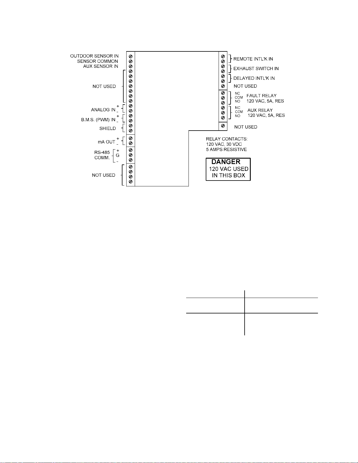
C-MORE CONTROL PANEL OPERATION
Figure 5-1. I/O Box Terminal Strip Connections
5.3 MODES OF OPERATION
KC Series Water Heaters are capable of being
operated in either the Constant Setpoint Mode
or Remote Setpoint Mode. In addition to the
Constant and Remote Setpoint Modes, KC and
Benchmark Series Boilers can also be operated
in the Direct Drive Mode, Boiler Management
System (BMS) Mode, Indoor/Outdoor Reset
Mode or Combination Mode.
The following paragraphs briefly describe the
required connections and menu settings to place
the unit in each of these modes.
5.3.1 Constant Setpoint Mode
The Constant Setpoint mode is used when a
fixed header temperature is desired. Common
uses of this mode of operation include water
source heat pump loops, and indirect heat
exchangers for potable hot water systems or
processes.
There are no external sensors necessary to
operate in this mode. While it is necessary to set
the desired setpoint temperature, it is not
necessary to change any other temperaturerelated functions. The unit is factory preset with
settings that work well in most applications.
Prior to changing any temperature-related
parameters, other than the setpoint, it is
suggested that an AERCO representative be
contacted. See Sections 2 and 3 for complete
listings of temperature related menu functions
and factory defaults.
5.3.1.1 Setting The Setpoint
The setpoint temperature of the unit is
adjustable from 40°F to 240°F.. To set the unit
for operation in the Constant Setpoint Mode, the
following menu settings must be made in the
Configuration Menu:
MENU OPTION SETTING
Boiler (or Heater)
Constant Setpoint
Mode
Internal Setpt Select desired setpoint
using ▲ and ▼ arrow
keys (40° to 240°F)
Refer to paragraph 2.2 for detailed instructions
on changing menu options.
5.3.2 Remote Setpoint Modes
The unit’s setpoint can be remotely controlled by
an Energy Management System utilizing either a
current or voltage signal level.
26
Page 31

C-MORE CONTROL PANEL OPERATION
The current/ voltage signal can be at either of
the following levels:
4 - 20 mA/1 - 5 Vdc
0 - 20 mA/0 - 5 Vdc
The factory default setting for the Remote
Setpoint mode is 4 - 20 mA/1 - 5 Vdc. With this
setting, a 4 to 20 mA/1 to 5 Vdc signal, sent by
an EMS or BAS, is used to change the unit's
setpoint. The 4 mA/1V signal is equal to a 40°F
setpoint while a 20 mA /5V signal is equal to a
240°F setpoint. When a 0 to 20 mA/0 to 5 Vdc
signal is used, 0 mA is equal to a 40°F setpoint.
In addition to the current and voltage signals
described above, the Remote Setpoint mode
can also be driven by a RS485 Modbus Network
signal from an EMS or BAS.
The Remote Setpoint modes of operation can be
used to drive single as well as multiple units.
NOTE
If a voltage, rather than current signal is
used to control the remote setpoint, a DIP
switch adjustment must be made on the
PMC Board located in the Control Panel
Assembly. Refer to Appendix F for details.
In order to enable the Remote Setpoint Mode,
the following menu setting must be made in the
Configuration Menu:
MENU OPTION SETTING
Boiler Mode Remote Setpoint
Remote Signal 4-20mA/1-5V,
0-20mA/0-5V, or
Network
Refer to paragraph 2.2 for detailed instructions
on changing menu options.
If the Network setting is selected for RS485
Modbus operation, a valid Comm Address must
be entered in the Setup Menu. Refer to Modbus
Communication Manual GF-114 for additional
information.
While it is possible to change the settings of
temperature related functions, the unit is factory
preset with settings that work well in most
applications. It is suggested that an AERCO
representative be contacted, prior to changing
any temperature related function settings. For
descriptions of temperature-related functions
and their factory defaults, refer to Tables 3-1
and 3-2.
5.3.2.1 Remote Setpoint Field Wiring
The only wiring necessary for the Remote
Setpoint modes is the external control wiring
from the source, to the ANALOG IN terminals on
the terminal strip inside the I/O Box. The I/O Box
is located on the left side of the KC Series units
and on the front of Benchmark Series units.
Refer to the wiring diagram (Figure 5-1)
provided on the cover of the I/O Box. For a
Network setting, the connections are made at
the RS-485 COMM terminals in the I/O Box. The
signal must be floating (ungrounded), and the
wire used must be a two wire shielded cable of
18 to 22 AWG. Polarity must be observed and
the source end of the shield must be connected
at the source. When driving multiple units, each
unit’s wiring must conform to the above.
5.3.2.2 Remote Setpoint Startup
Since this mode of operation is factory preset
and the setpoint is being externally controlled,
no startup instructions are necessary. In this
mode, the REMOTE LED will light when the
external signal is present.
To operate the unit in manual mode, press the
AUTO/MAN switch. The REMOTE LED will go
off and the MANUAL LED will light
To change back to the Remote Setpoint mode,
simply press the AUTO/MAN switch. The
REMOTE LED will again light and the MANUAL
LED will go off.
NOTE:
The modes of operation described in
paragraphs 5.3.3 through 5.3.6 apply ONLY
to KC and Benchmark Series Boilers.
External wiring connections for these modes
are made at the Input/Output (I/O) Box
which is located on the left side of KC
Series units and on the front of Benchmark
Series units.
5.3.3 Indoor/Outdoor Reset Mode
This mode of operation is based on outside air
temperatures. As the outside air temperature
decreases, the supply header temperature will
increase and vice versa. For this mode, it is
necessary to install an outside air sensor as well
as select a building reference temperature and a
reset ratio.
27
Page 32

C-MORE CONTROL PANEL OPERATION
5.3.3.1 Reset Ratio
Reset ratio is an adjustable number from 0.1 to
9.9. Once adjusted, the supply header
temperature will increase by that number for
each degree that the outside air temperature
decreases. For instance, if a reset ratio of 1.6 is
used, for each degree that outside air
temperature decreases, the supply header
temperature will increase by 1.6 degrees.
5.3.3.2 Building Reference Temperature
This is a temperature from 40°F to 230°F. Once
selected, it is the temperature that the system
references to begin increasing its temperature.
For instance, if a reset ratio of 1.6 is used, and
we select a building reference temperature of
70°F, then at an outside temperature of 69°F,
the supply header temperature will increase by
1.6° to 71.6°F.
5.3.3.3 Outdoor Air Temperature Sensor
Installation
The outdoor air temperature sensor must be
mounted on the North side of the building in an
area where the average outside air temperature
is expected. The sensor must be shielded from
the sun's direct rays, as well as direct
impingement by the elements. If a cover or
shield is used, it must allow free air circulation.
The sensor may be mounted up to two hundred
feet from the unit. Sensor connections are
made inside the Input/Output (I/O) Box at the
terminals labeled OUTDOOR SENSOR IN and
SENSOR COMMON using shielded 18 to 22
AWG wire. A wiring diagram is provided on the
cover of the I/O Box. Refer to Section 2 of
Operation & Maintenance Manual GF-109 (KC
Series) or GF-110 (Benchmark Series) for
additional wiring information.
5.3.3.4 Indoor/Outdoor Startup
1. Refer to the indoor/outdoor reset ratio charts
in Appendix C.
2. Choose the chart corresponding to the
desired building reference temperature.
3. Go down the left column of the chart to the
coldest design outdoor air temperature
expected for your area.
NOTE:
A design engineer typically provides design
outdoor air temperature and supply header
temperature data
4. Once the design outdoor air temperature is
5. Next, go up that column to the Reset Ratio
6. Access the Configuration Menu and scroll
7. Press the CHANGE key. The display will
8. Use the ▲ and ▼ arrow keys to select the
9. Press ENTER to save any changes.
10. Next, scroll through the Configuration Menu
11. Press the CHANGE key. The display will
12. Use the ▲ and ▼ arrow keys to select the
13. Press ENTER to save the change.
Refer to paragraph 2.2 for detailed instructions
on menu changing.
5.3.4 Direct Drive Modes
The boiler’s fire rate can be changed by a
remote signal typically sent from an energy
management system. The Direct Drive modes
are driven by current or voltage signals in the
following ranges:
4 - 20 mA/1 - 5 Vdc
0 - 20 mA/0 - 5 Vdc
The factory default setting is 4 - 20 mA/1 - 5
Vdc. In this mode of operation, a 4 to 20mA
signal, sent by an energy management system,
is used to change the boiler’s fire rate from 0%
to 100%. The 4 mA/1Vdc signal is equal to a 0%
fire rate while a 20 mA /5Vdc signal is equal to a
100% fire rate. When a 0-20 mA/0-5 Vdc signal
is used, zero is equal to a 0% fire rate.
In addition to the current and voltage signals
described above, the Direct Drive mode can also
be driven by a RS-485 Modbus Network signal
from an EMS or BAS.
chosen, go across the chart to the desired
supply header temperature (setpoint) for the
design temperature chosen in step 3.
row to find the corresponding reset ratio.
through it until the display shows Bldg Ref
Temp (Building Reference Temperature).
begin to flash.
desired building reference temperature.
until the display shows Reset Ratio.
begin to flash.
reset ratio determined in step 5.
28
Page 33

C-MORE CONTROL PANEL OPERATION
When in a Direct Drive mode, the boiler is a
slave to the energy management system and
does not have a role in temperature control.
Direct Drive can be used to drive single as
well as multiple boilers.
NOTE:
If a voltage, rather than current signal is used
to control the remote setpoint, a DIP switch
adjustment must be made on the PMC
Board in the Control Box. Refer to Appendix
F for details.
To enable the Direct Drive Mode, the following
menu setting must be made in the Configuration
Menu:
MENU OPTION SETTING
Boiler Mode Direct Drive
Remote Signal 4-20mA/1-5V,
0-20mA/0-5V, or
Network
Refer to paragraph 2.2 for instructions on
changing menu options
If the Network setting is selected for RS485
Modbus operation, a valid Comm Address must
be entered in the Setup Menu. Refer to Modbus
Communication Manual GF-114 for additional
information.
5.3.4.1 Direct Drive Field Wiring
The only wiring necessary for Direct Drive
mode is connection of the remote signal leads
from the source to the ANALOG IN terminals
at the I/O Box. For a Network setting, the
connections are made at the RS-485 COMM
terminals in the I/O Box. The signal must be
floating, (ungrounded), and the wire used must
be a two wire shielded cable of 18 to 22 AWG.
Polarity must be observed. The source end of
the shield must be connected at the source.
When driving multiple units, each unit’s wiring
must conform to the above.
5.3.4.2 Direct Drive Startup
Since this mode of operation is factory preset
and the fire rate is being externally controlled,
no startup instructions are necessary. In this
mode, the REMOTE LED will light when the
signal is present.
To operate the boiler in manual mode, press the
MAN switch. The REMOTE LED will go off and
the MANUAL LED will light.
.
To change back to the Direct Drive mode, simply
press the AUTO switch. The REMOTE LED will
again light and the MANUAL LED will go off.
5.3.5 Boiler Management System (BMS)
NOTE
BMS Model 168 can utilize either pulse
width modulation (PWM) or RS485
Modbus signaling to the Boiler. BMS II
Model 5R5-384 can utilize only RS485
signaling to the Boiler.
The BMS mode of operation is used in
conjunction with an AERCO Boiler Management
System. The BMS mode is used when it is
desired to operate multiple units in the most
efficient manner possible. The BMS can control
up to 40 boilers; 8 via pulse width modulation
(PWM) and up to 32 via Modbus (RS485)
network communication. For BMS programming
and operation, see GF-108M (BMS Model 168)
and GF-124 (BMS II Model 5R5-384), BMS
Operations Guides. For operation via an RS485
Modbus network, refer to Modbus
Communication Manual GF-114. The AERCO
BMS monitors all system-related parameters
and modulates the firing rates of the units.
To enable the BMS Mode, the following menu
settings must be made in the Configuration
Menu:
MENU OPTION SETTING
Boiler Mode Direct Drive
Remote Signal BMS (PWM Input)
or
Network (RS485)
Refer to paragraph 2.2 for instructions on
changing menu options.
5.3.5.1 Boiler Management System External
Field Wiring
Wiring for this system configuration is connected
between the BMS panel Model 168, boilers 1
through 8, to the B.M.S. (PWM) IN terminals in
the I/O Box on the Boiler. Refer to the wiring
diagram provided on the cover of the I/O Box.
Wiring connections for RS485 Modbus control
are made between connector JP11 on the BMS
Model 168 (boilers 9 to 40)/or JP6 on BMS II
Model 5R5-384 (boilers 1 to 32 and the RS485
COMM terminals in the I/O Box.
29
Page 34

C-MORE CONTROL PANEL OPERATION
Wire the units using shielded twisted pair wire
between 18 and 22 AWG. Observe the polarity
shown for the B.M.S. (PWM) IN connections.
The shield is connected at the BMS to any
minus (-) boiler terminal and the boiler end of the
shield must be left floating. Each unit’s wiring
must conform to the above.
5.3.5.2 Boiler Management System Setup
and Startup
This mode of operation is factory preset and the
AERCO BMS Model 168 controls the firing rate.
There are no setup instructions for each
individual unit.
To operate the unit in manual mode, press the
AUTO/MAN switch. The REMOTE LED will go
off and the MANUAL LED will light
To change back to the BMS mode, simply press
the AUTO/MAN switch. The REMOTE LED will
again light and the MANUAL LED will go off.
5.3.6 Combination Control System
(CCS)
NOTE
Only BMS Model 168 can be utilized for
the Combination Mode, not
(Model 5R5-384).
A Combination Control System is one that uses
multiple boilers to cover both space-heating and
domestic hot water needs. An AERCO Boiler
Management System (BMS Model 168) and a
Combination Control Panel (CCP) are necessary
to configure this system. Typically, enough
boilers are installed to cover the space-heating
load on the design day, however one or more
units are used for the domestic load.
The theory behind this type of system is that the
maximum space-heating load and the maximum
domestic hot water load do not occur
simultaneously. Therefore, boilers used for the
domestic hot water are capable of switching
between constant setpoint and BMS modes of
operation. These boilers are the combination
units and are referred to as the combo boilers.
The combo boilers heat water to a constant
setpoint temperature. That water is then
circulated through a heat exchanger in a
domestic hot water storage tank.
When the space-heating load is such that all the
space-heating boilers are at 100% firing rate, the
BMS will then ask the Combination Control
the BMS II
Panel for the domestic boilers to become spaceheating boilers. Provided the domestic hot
water load is satisfied, the combo (hot water)
boilers will then become space-heating boilers.
If the domestic hot water load is not satisfied,
the combo boiler(s) remain on the domestic hot
water load. If the combo boilers switch over to
space heating, but there is a call for domestic
hot water, the CCP switches the combo units
back to the domestic load.
When the combo units are satisfying the
domestic load they are in constant setpoint
mode of operation. When the combo units
switch over to space heating, their mode of
operation changes to the BMS mode. For more
information concerning the operation of the
Combination Control Panel see the AERCO
CCP-1 literature.
5.3.6.1 Combination Control System Field
Wiring
Wiring for this system is between the BMS
panel, the CCP and the B.M.S. (PWM) IN
terminals in the I/O Box. Wire the units using a
shielded twisted pair of 18 to 22 AWG wire.
When wiring multiple units, each unit’s wiring
must conform to the above. For a complete CCP
system-wiring diagram see the AERCO CCP-1
literature.
5.3.6.2 Combination Control System Setup
and Startup
Setup for the Combination Mode requires entries
to be made in the Configuration Menu for boiler
mode, remote signal type and setpoint. The
setpoint is adjustable from 40°F to 220°F.
Enter the following settings in the Configuration
Menu:
MENU OPTION SETTING
Boiler Mode Combination
Remote Signal BMS (PWM) Input
Internal Setpt 40°F to 240°F
Refer to paragraph 2.2 for instructions on
changing menu options.
While it is possible to change other temperaturerelated functions for combination mode, the unit
is factory preset. These preset settings work
well in most applications. It is suggested that
AERCO be contacted prior to changing settings
other than the unit’s setpoint.
30
Page 35

C-MORE CONTROL PANEL OPERATION
5.4 START SEQUENCE
When the unit is in the Standby mode and all
pre-purge safety switches are closed, the
READY light above the ON/OFF switch will be
lit. When there is a demand for heat, the
following events will occur:
NOTE:
If any of the Pre-Purge safety switches (low
water level, high water temperature, high or
low gas pressure) are open, the appropriate
fault message will be displayed. Also, the
appropriate fault messages will be displayed
throughout the start sequence, if the
required conditions are not observed.
1. The DEMAND LED status indicator will light.
2. The unit checks the proof of closure switch
on the Safety Shut-Off Valve (SSOV) shown
in Figure 5-2.
switch. The dial on the Air/Fuel Valve
(Figure 5-3) will read 100 to indicate that
the valve is full-open (100%).
(c) The FIRE RATE bargraph will show
100%.
NOTE:
The Air/Fuel Valves shown in Figures 5-3
and 5-5 are used on KC Series units.
Although slight physical differences exist
between the Air/Fuel Valves used on
Benchmark Series units, the valves are
functionally identical.
STEPPER
MOTOR
Figure 5-2. Proof of Closure Switch
3. With all required safety switches closed, a
purge cycle will be initiated and the following
events will occur:
(a) Blower relay energizes and turns on
blower.
(b) Air/Fuel Valve rotates to the full-open
purge position and closes purge position
DIAL
(DETAIL “A”)
100
DETAIL "A"
Figure 5-3.
KC1000 Air/Fuel Valve In Purge Position
4. Next, the blower proof switch (Figure 5-4)
closes and the display will show Purging and
indicate the elapsed time of the purge cycle
in seconds. The normal (default) time for the
purge cycle is 7 seconds.
31
Page 36

C-MORE CONTROL PANEL OPERATION
7. With the unit firing properly, it will be
controlled by the temperature controller
circuitry. The FIRE RATE will be
continuously displayed on the front panel
bargraph.
8. Once the demand for heat has been
satisfied, the Control Box will turn off the gas
valve. The blower relay will be deactivated
and the Air/Fuel Valve will be closed.
Standby will be displayed.
Figure 5-4.
Blower Proof Switch
5. Upon completion of the purge cycle, the
Control Box initiates an ignition cycle and the
following events occur:
(a) The Air/Fuel Valve rotates to the low-fire
ignition position and closes the ignition
switch. The dial on the Air/Fuel Valve
(Figure 5-5) will read between 25 and 35
to indicate that the valve is in the lowfire position.
(b) The igniter relay is activated and
provides ignition spark.
STEPPER
MOTOR
DIAL
(DETAIL “A”)
(c) The gas Safety Shut Off Valve (SSOV)
is energized (opened) allowing gas to
flow into the Air/Fuel Valve. Up to 7
seconds will be allowed for ignition to be
detected. The igniter relay will be turned
off one second after flame is detected.
6. After 2 seconds of continuous flame, Flame
Proven will be displayed and the flame
strength will be indicated. After 5 seconds,
the current date and time will be displayed in
place of the flame strength.
2
5
DETAIL "A"
Figure 5-5.
KC1000 Air/Fuel Valve In Ignition Position
32
Page 37

C-MORE CONTROL PANEL OPERATION
SECTION 6 - CALIBRATION AND DIAGNOSTIC MENUS
6.1 INTRODUCTION
The Level 2 Password (6817) must be entered
to access the Calibration and Diagnostic
procedures describe in this Section.
6.2 CALIBRATION PROCEDURES
The items contained in the Calibration Menu
shown in Table 2-5 permit the user to set or
adjust a number of functions in the KC and
Benchmark Series units. The descriptions and
procedures necessary to implement each of
these Calibration Items are provided in the
following paragraphs.
6.2.1 Stepper Feedback Calibration.
The Stepper Feedback (Fbk) function checks
the calibration of the Air/Fuel Valve Stepper
Motor feedback current. This is accomplished by
positioning the Air/Fuel Valve stepper motor at
the 0% (fully closed) and 100% (fully open)
positions and storing the feedback potentiometer
readings at these settings. It also permits
verification of the Stepper Motor Feedback at
the 50% position. The position of the Stepper
Motor is verified by visually checking the dial on
the Air/Fuel Valve. In addition, the FIRE RATE
bargraph segments will light to indicate motor
position. To initiate this calibration procedure,
proceed as follows:
1. Press the ▲ or ▼ arrow key until Stepper
Fbk Cal 0% is displayed.
2. Press the CHANGE key. Stepper Fbk will
begin to flash.
3. Press and hold the ▼ arrow key and monitor
the dial on the Air/Fuel Valve.
4. Release the ▼ arrow key when the Air/Fuel
Valve reaches the 0% (fully closed) position,
but is not pressing against the stop.
Momentarily tap the ▲ arrow key a few times
to ensure it is not contacting the stop.
5. Press the ENTER key. Cal 100% will be
displayed.
6. Press and hold the ▲ arrow key and monitor
the dial on the Air/Fuel Valve.
7. Release the ▲ arrow key when the Air/Fuel
Valve reaches the 100% (fully open) position,
but is not pressing against the stop.
Momentarily tap the ▼ arrow key a few times
to ensure it is not contacting the stop.
8. Press the ENTER key. Verify 50% will be
displayed and the Air/Fuel Valve will rotate to
the 50% position.
9. Verify that the dial on the Air/Fuel Valve
indicates approximately 50%. Press ENTER
to confirm.
10. Press BACK to exit the Stepper Fbk
Calibration.
6.2.2 PWM In Adjustment.
The Pulse Width Modulation (PWM) Input
Adjustment is used when the unit is being
controlled by a Boiler Management System
(BMS). This Calibration procedure allows the
PWM duty cycle to be varied ±5.0% in 0.1%
increments. The nominal PWM duty cycle is 12
milliseconds where: a 5% pulse ON time = a 0%
firing rate and a 95% pulse ON time represents
a 100% firing rate. To adjust the overall PWM
duty cycle, proceed as follows:
1. Press the ▲ or ▼ arrow key until PWM In
Adj is displayed along with the currently
entered adjustment percentage.
2. If the desired percentage is not displayed,
press the CHANGE key. PWM In Adj will
begin to flash.
3. Press the ▲ or ▼ arrow key to increment or
decrement the display until the desired
adjustment percentage is displayed.
4. Press ENTER to store the selection.
5. Pres BACK to exit the adjustment procedure.
6.2.3 Analog In Adjustment
The Analog Input Adjustment may be utilized
when an external signal is used to change the
setpoint (Remote Setpoint Mode – Boiler or
Heater), or drive the firing rate Direct Drive
Mode – Boiler Only). This adjustment allows the
0 to 20 mA or 1 to 5 Vdc input to be changed
±5.0% in 0.1 % increments. The default setting
is 0.0%. To view or change this adjustment,
proceed as follows:
33
Page 38

C-MORE CONTROL PANEL OPERATION
1. Press the ▲ or ▼ arrow key until Analog In
Adj is displayed along with the current
adjustment percentage
2. If the desired percentage is not displayed,
press the CHANGE key. Analog In Adj will
begin to flash.
3. Press the ▲ or ▼ arrow key to increment or
decrement the display until the desired
adjustment percentage is displayed.
4. Press ENTER to store the selection.
5. Pres BACK to exit the adjustment procedure.
6.2.8 A/F Sensitivity
The Air/Fuel (A/F) Valve Sensitivity is used to
set the allowable error on the Air/Fuel Valve
Stepper Motor position. The sensitivity is
adjustable from 1% to 5% in 1% increments.
The default value for this setting is 2%. The
sensitivity setting represents the maximum
percentage that the output fire rate can change
without the valve having to move. For example;
if the sensitivity is set for 2% and the output fire
rate changes 1%, no movement is required. To
view or change the A/F Sensitivity, proceed as
follows:
6.2.4 Flow In Adjustment.
The Flow Input Adjustment is not currently
implemented in the C-More Control Panel. When
implemented, it will allow the water flow rate
measured by a flow sensor to be adjusted ± 5%.
6.2.5 CO In Adjustment.
The Carbon Monoxide (CO) Input Adjustment is
not currently implemented in the C-More Control
Panel. When implemented, it will allow input flow
rate to be adjusted ±5%.
6.2.6 O2 In Adjustment
The Oxygen (O2) Input Adjustment is not
currently implemented in the C-More Control
Panel. When implemented, it will allow the input
oxygen level to be adjusted ±5%.
6.2.7 mA Out Adjustment
The Milliamp (mA) Output Adjustment permits
the output current to be adjusted from -1.0 mA to
+1.0 mA in 0.1 mA increments. The default
setting is 0.0 mA. This function is associated
with the mA OUT terminals in the I/O Box.
These terminals provide an output that can be
used to monitor setpoint, outlet temperature or
fire rate. The function to be monitored is
selected in the Configuration Menu. To view or
adjust this setting, proceed as follows:
1. Press the ▲ or ▼ arrow key until mA Out Adj
is displayed along with the current
adjustment setting in mA.
2. If the desired setting is not displayed, press
the CHANGE key. mA Out Adj will begin to
flash.
3. Press the ▲ or ▼ arrow key to increment or
decrement the display until the desire value
appears.
4. Press ENTER to store the displayed setting.
1. Press the ▲ or ▼ arrow key until A/F
Sensitivity is displayed. The currently set
sensitivity percentage will also appear in the
display.
2. If the desired percentage is not displayed,
press the CHANGE key. A/F Sensitivity will
begin to flash.
3. Press the ▲ or ▼ arrow key to increment or
decrement the displayed sensitivity
percentage to the desired value.
4. Press ENTER to store the new setting.
5. Press BACK to exit the A/F Sensitivity
Calibration.
6.2.9 Power Reset
The Power Reset function can be set to
Automatic or Manual. However, AERCO strongly
recommends that this function always be set to
the Automatic (Default) setting.
6.2.10 Water Temp Reset
The Water Temperature Reset function can be
set to Automatic or Manual to indicate whether
the unit can be restarted or must wait for manual
acknowledgement following a high water
temperature fault and fault correction.
Regardless which setting is used, the High
Temperature fault message will be latched. The
default for this function is Automatic. To view or
change the setting, proceed as follows:
1. Press the ▲ or ▼ arrow key until Water
Temp Reset is displayed. Automatic or
Manual will be displayed to indicate the
present setting.
2. If the desired setting is not displayed, press
the CHANGE key. Water Temp Reset will
begin to flash.
3. Press ENTER to toggle the display.
5. Press BACK to exit the mA Out Adj function.
34
Page 39

C-MORE CONTROL PANEL OPERATION
4. Press BACK to exit the Water Temp Reset
function.
6.2.11 Gas Press Reset
The Gas Pressure Reset function can be set to
Automatic or Manual to indicate whether the unit
can be restarted or must wait for manual
acknowledgement following a high or low gas
pressure fault and fault correction. The default
setting for this function is Manual. Regardless
which setting is used, the High or Low Gas
Pressure fault message will be latched. The
default for this function is Manual. To view or
change the setting, proceed as follows:
IMPORTANT:
DO NOT change this setting to Automatic
without written permission from AERCO.
1. Press the ▲ or ▼ arrow key until Gas Pres
Reset is displayed. Automatic or Manual will
be displayed to indicate the present setting.
2. If the desired setting is not displayed, press
the CHANGE key. Gas Press Reset will
begin to flash.
3. Press ENTER to toggle the display.
4. Press BACK to exit the Gas Press Reset
function.
6.2.12 Min Off Time
The Minimum Off Time specifies the minimum
amount of time that the unit must remain off
when operating under automatic control. This
time is adjustable from 0 to 10 minutes in 1
minute increments. The default value is 1
minute. To view or change this setting, proceed
as follows:
1. Press the ▲ or ▼ arrow key until Min Off
Time is displayed. The present setting will
also appear in the display.
2. If the desired minimum off time is not
displayed, press the CHANGE key. Min Off
Time will begin to flash.
3. Press the ▲ or ▼ arrow key to increment or
decrement the displayed until the desired
value is shown.
Heater Tuning Display
The Heater Tuning Display function can be set
to Enable or Disable (Default = Disable). When
Enabled, it permits the Prop Band, Integral Gain
and Derivative Time functions in the Tuning
Menu to be set. See Table 2-4 for entry ranges.
6.2.14 Heater Breakpoint Display
This menu option is applicable only to Water
Heaters and can be set to Enable or Disable
(Default = Disable). When Enabled, it permits
the Heater Breakpoints listed in the Tuning
Menu (Table 2-4) to be viewed or changed.
6.3 DIAGNOSTICS PROCEDURES
The Diagnostics Menu Items listed in Table 2-6
permit the user to check the operational status
of the front panel controls indicators and
displays and the control system relays and
switches. To perform each of the following
Diagnostic procedures, first scroll to the
Diagnostics Menu using the MENU key and
press the ▲ or ▼ arrow key. Proceed to the
desired Diagnostic procedure specified in the
following paragraphs.
6.3.1 Display Test
The Display Test checks the front panel LED
indicators, 7-segment display and LED FIRE
Rate bargraph.
1. Press the ▲ or ▼ arrow key until Display
Test Off is displayed.
2. Press the CHANGE key. Display Test will
begin to flash.
3. Press the ▲ key. LEDs will be displayed and
the seven panel LEDs will light. These LEDs
are: COMM, MANUAL, REMOTE,
DEMAND, °F, °C and FAULT.
4. Press the ▲ key. 7-SEG will be displayed
and all segments of the three-digit 7-segment
display will light.
5. Press the ▲ key. Bar-graph will be displayed
and the 20 segment FIRE RATE bargraph
will light.
6. This completes the Display Test. Press the
BACK key to exit the test.
6.3.2
4. Press ENTER to store the new setting.
5. Press BACK to exit the Min Off Time
function.
6.2.13
35
Page 40

C-MORE CONTROL PANEL OPERATION
Keypad Test
The Keypad Test checks the status of the eight
keypad keys on the front panel. The test is
initiated as follows:
1. Press the ▲ or ▼ arrow key until Keypad
Test Off is displayed.
2. Press the CHANGE key. Keypad Test will
begin to flash.
(a) Aux
(b) Pump
(c) Blower
(d) Igniter
6. Pressing the ▼ arrow key will display the
previous relay.
7. Press the BACK key to exit the Relay Test.
3. Press each of the keys in the following
sequence and verify that the name of each
key appears in the panel display:
(a) AUTO/MAN (Manual is displayed).
(b) MENU
(c) ▲ (Up is displayed)
(d) ▼ (Down is displayed)
(e) CHANGE
(f) ENTER
(g) CLEAR
4. Press the BACK key to exit the Keypad Test.
6.3.3 Relay Test
The Relay Test allows the user to switch relays
ON or OFF. The relays which are tested are:
Igniter, Blower, Pump, Aux and Fault relays.
The Aux and Fault relays are located in the I/O
Box on the left side of the unit. Removing the
cover on the I/O Box will permit the ON/OFF
status of these relays to be observed. The
remaining relays are located in the C-More
Control Panel. A “click” can be heard as each
relay is turned ON and OFF.
1. Press the ▲ or ▼ arrow key until Relay Test
Off is displayed.
2. Press the CHANGE key. Relay Test will
begin to flash.
3. Press the ▲ arrow key. Fault OFF will be
displayed.
4. To switch relay to ON, press ENTER. Fault
ON will be displayed. Press ENTER again to
toggle relay back to OFF. The ON/OFF
status of this relay can be observed with the
I/O Box cover removed.
5. To change the ON/OFF status of the
remaining relays, repeat steps 3 and 4. The
display will show the relays in the following
order:
6.3.4 Switch Test
The Switch Test allows the user to observe the
ON/OFF status of all control system switches in
“Real Time”. However, the displayed status can
not be changed. This test is useful in
determining that all required switches in the
“Start String” on in the required positions to
permit system startup.
1. Press the ▲ or ▼ arrow key until Switch Test
Off is displayed.
2. Press the CHANGE key. Switch Test will
begin to flash.
3. Press the ▲ arrow key. Exhaust sw will be
displayed along with the present ON/OFF
switch status.
4. To check the status of the remaining
switches, continue to press the ▲ arrow key.
The switch status will be displayed in the
following order:
(a) SSOV sw
(b) Blower Proof sw
(c) Ignition sw
(d) Over Temp sw
(e) Low Gas Pres
(f) Hi Gas Pres
(g) Water Lev sw
(h) Rem Int sw
(i) Front Pnl sw
(j) Delayed Int
(k) Purge sw
5. Press the BACK key to exit the Switch Test.
6.3.5
36
Page 41

C-MORE CONTROL PANEL OPERATION
Stepper Test
The Stepper Test allows e
Stepper Motor to be rotated between virtually
any position between 0% (fully closed) and
100% (fully open).
1. Press the ▲ or
Test 0% is displayed.
2. Press the CHANGE ill
begin to flash.
3. Press and hold
the Stepper Motor position. The FIRE RATE
bargraph will increase to show the valve
position and the dial on the Air/Fuel valve will
also rotate to track the current position.
4. Press and hold the ▼ arrow ke
decrement the Stepper Motor position and
verify that bargraph display and Air/Fuel
Valve dial track the change.
▼ arrow key until Stepper
the ▲ arrow key to increment
6.3.6 Sensor Log Int
The Sensor Log Interval func
user to set the interval at which sensor readings
are recorded and stored in memory. By default,
this option is set to OFF. However, if desired,
the Sensor Log Interval can be enabled and set
to values ranging from 1 minute to 24 hours.
the Air/Fuel Valv
key. Stepper Test w
y to
tion permits the
. Press the ▲ or ▼ arrow key until Sensor L
1
Int Off is displayed.
2. Press the CHANGE key. Sensor Log Int will
begin to flash.
3.
Press the ▲ arrow key until the desired
interval is disp
are:
(a) 1 Min
(b) 5 Min
(c) 15 Min
(d) 30 Min
(e) 1 hr
(f) 6 hrs
(g) 12 hrs
(h) 24 hrs
4. With the des
ENTER to sto
5. Press BACK to exit the Sensor Log Int
function.
layed. The available choices
ired interval displayed, press
re the selection in memory.
og
37
Page 42

C-MORE CONTROL PANEL OPERATION
SECTION 7 - RS232 COMMUNICATION
7.1 INTRODUCTION
The RS232 port on the front panel can be
interfaced to a laptop computer or other suitable
terminal using a RS232 adapter cable. RS232
communication can be accomplished using any
“Dumb Terminal” emulation, such as “Hyper
Terminal” which is included with Microsoft
Windows. The RS232 communication feature
permits viewing or changing of Control Panel
menu options and also provides access to data
logs showing Event Time Line, Fault and Sensor
log displays.
7.2 RS232 COMMUNICATION SETUP
Regardless of the terminal emulation utilized,
the following guidelines must be adhered to
when setting up the RS232 communication link:
1. Baud Rate – The baud rates which can be
used with the C-More Control Panel are:
(a) 2400
(b) 4800
(c) 9600 (Default)
(d) 19.2K
2. Data Format – The program must be set for:
8 data bits, 1 stop bit, no parity and either
Xon/Xoff or No flow control.
7.3 MENU PROCESSING UTILIZING
RS232 COMMUNICATION.
Viewing data logs and viewing or changing
Control Panel menu options using RS232
communication is accomplished as follows:
1. Start the emulator software program and
ensure that the specified baud rate and data
formats have been entered.
2. Press the Enter key on the laptop. An
asterisk (*) prompt should appear.
3. At the prompt, enter the valid RS232
password (jaguar) in lower case letters and
press Enter.
4. “Welcome to Aerco” will appear in the laptop
or “dumb terminal” display with a listing of the
following available entry choices:
M = Display next Menu
D = Display menu items
N = Display next menu items
Cxx = Change item xx
F = Fault log display
S = Sensor log display
T = Time line display
L = Log off
NOTE:
The Level 1 password must be entered to
change options in the Setup, Configuration
and Tuning Menus. The Level 2 password
must be entered to view or change options
in the Calibration and Diagnostics Menus.
With the exception of the password entry, all
other keyboard entries can be made using
either upper or lower case.
5. To view the available menus in the top-down
sequence shown in Figure 2-1, enter M
<Rtn>. The Menu title and first 10 options will
be displayed.
6. When viewing menus containing more than
10 options, enter N <Rtn> to display the
remaining options.
7. Shortcut keys are also available to go directly
to a specific menu. These shortcut keys are:
m0 Default (Operating) Menu
m1 Setup Menu
m2 Configuration Menu
m3 Tuning Menu
m4 Calibration Menu
m5 Diagnostic Menu
8. To change a value or setting for a displayed
menu option, proceed as follows:
(a) Enter C, followed by the number to the
right of the displayed option to be
changed, and then press <Rtn>.
(b) Enter the desired value or setting for the
option and press <Rtn>. Refer to Tables
2-1 through 2-6 for allowable entry
ranges and settings.
(c) The change will be stored in non-volatile
memory.
38
Page 43

C-MORE CONTROL PANEL OPERATION
9. To redisplay the menu and view the option
which was just changed in step 5, enter D
and press <Rtn>.
10. To display the Fault (F) Log, Sensor (S) Log
or Time (T) Line Log, press F, S or T
followed by <Rtn>. Refer to paragraph 7.4 for
descriptions and samples of these data logs.
11. To log off and terminate the RS232 com-
munication link, press L followed by <Rtn>.
7.4 DATA LOGGING
During operation, the C-More Control Panel
continuously monitors and logs data associated
with operational events, faults and sensor
readings associated with the boiler or water
heater system. Descriptions of these data logs
are provided in the following paragraphs. The
basic procedure for accessing each data log is
described in paragraph 7.3, step 7.
7.4.1 Fault Log
The C-More Control Panel logs the last 10 faults
(0 – 9) starting with the most recent (#0). They
can be viewed in the front panel display or via
the RS232 port. The Fault Log cannot be
cleared. If the Fault Log already contains 10
faults, the earliest fault is overwritten when a
new fault occurs. A sample Fault Log display is
shown in Table 7-1.
NOTE:
The Operation Time (T) Log can store
thousands of records. Therefore, to view the
most recently logged record, enter “T”
followed by 0 (zero) and press Enter
(i.e. T0 <Enter>). To view earlier records in
reverse chronological order, enter T and
press Enter. To go back 200 or 1000
records, enter T200 or T1000, etc. and
press Enter.
7.4.2 Operation Time Log
The Operation Time Log consists of a string of
ASCII records stored in non-volatile memory
within the C-More Control Panel. Events such
as power-up, ignition and turn-off are time
stamped. Data logged while the unit is running
are run-length encoded. Data is logged or the
run-length incremented every 30 seconds. For a
new run record to be logged, the fire rate or
flame strength must change by more than 5%,
or the run mode must change. At steady-state,
the run-length is allowed to reach a maximum of
30 minutes before the record is logged. This
means that no more than 30 minutes of data can
be lost if the unit loses power. Table 7-2 shows
a sample Operation Time Log for a boiler:
The Operation Time Log can only be accessed
through the RS232 interface using a laptop or
other terminal device. Ten operation time
records are displayed for each T command
entry. The operation time log can be cleared
ONLY by factory authorized personnel using the
Clear Log option in the Factory menu.
NOTE:
The Sensor (S) Log can store up to 1200
records. Therefore, to view the most
recently logged record, enter “S” followed by
0 (zero) and then press Enter
(i.e. S0 <Enter>). To view earlier records in
reverse chronological order, enter S and
press Enter. To go back 200 or 700
records, enter S200 or S700, etc. and press
Enter.
7.4.3 Sensor Log
The sensor values can be logged at a different
rate if needed by setting the Sensor Log Interval
in the Diagnostics Menu. The log interval can
vary from once every minute to once every day.
Table 7-3 shows a sample Sensor Log every 5
minutes for a boiler running in Constant Setpoint
mode.
39
Page 44

C-MORE CONTROL PANEL OPERATION
Table 7-1. Sample Fault Log Display
No. Fault Message Cycle Date Time
0 Direct Drive Signal Fault 609 1/10/02 8:42am
1 Low Gas Pressure 366 7/04/01 5:29pm
2 Loss of Power 0 1/01/01 11:50am
Table 7-2. Sample Operation Time Log Display
Status Fire Rate Flame Run Length Date Time
Off, Direct Drive 0 0 8 1/15/02 2:35pm
Run, Direct Drive 38 100 34 1/15/02 2:27pm
Run, Direct Drive 31 100 30 1/15/02 1:53am
Run, Direct Drive 35 100 2 1/15/02 1:23pm
Run, Direct Drive 29 100 0 1/15/02 1:21pm
Ignition 0 0 0 1/15/02 1:20pm
Off, Switch 0 0 35 1/15/02 12:30pm
Run, Manual 40 100 0 1/15/02 11:55am
Ignition 0 0 0 1/15/02 11:55am
Power-up 0 0 0 1/15/02 11:50am
Table 7-3. Sample Sensor Log Display
Setpt Outlet Outdr FFWD Aux Inlet Exhst CO O2 Flow Date Time
130 181 OPEN OPEN OPEN OPEN OPEN 0 .0 0 1/15/02 5:51pm
130 180 OPEN OPEN
130 180 OPEN OPEN OPEN OPEN OPEN 0 .0 0 1/15/02 5:41pm
130 179 OPEN OPEN OPEN OPEN OPEN 0 .0 0 1/15/02 5:36pm
130 180 OPEN OPEN OPEN OPEN OPEN 0 .0 0 1/15/02 5:31pm
130 180 OPEN OPEN OPEN OPEN OPEN 0 .0 0 1/15/02 5:26pm
130 180 OPEN OPEN OPEN OPEN OPEN 0 .0 0 1/15/02 5:21pm
130 180 OPEN OPEN OPEN OPEN OPEN 0 .0 0 1/15/02 5:16pm
130 179 OPEN OPEN OPEN OPEN OPEN 0 .0 0 1/15/02 5:11pm
130 180 OPEN OPEN OPEN OPEN OPEN 0 .0 0 1/15/02 5:06pm
OPEN OPEN OPEN 0 .0 0 1/15/02 5:46pm
40
Page 45

APPENDIX A
APPENDIX A
C-MORE CONTROL PANEL VIEWS
A-1
Page 46

APPENDIX A
A-2
CONTROL PANEL EXPLODED VIEW – KC SERIES SYSTEMS
Page 47
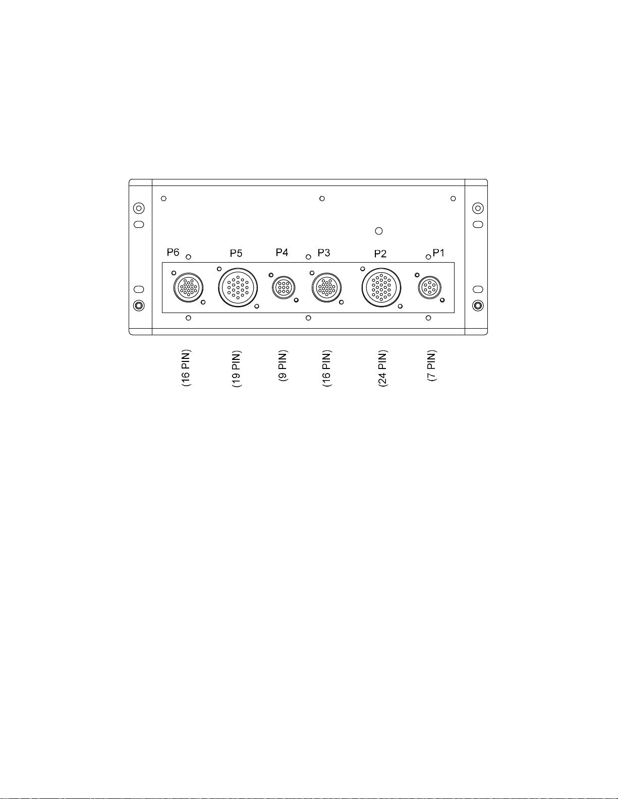
APPENDIX A
CONTROL PANEL REAR VIEW – KC SERIES SYSTEMS
A-3
Page 48

APPENDIX A
A-4
CONTROL PANEL EXPLODED VIEW – BENCHMARK SERIES SYSTEMS
Page 49

APPENDIX A
P6
P5
P4
P3
P2
P1
CONTROL PANEL REAR VIEW – BENCHMARK SERIES SYSTEMS
+
A-5
Page 50

Page 51

APPENDIX B
APPENDIX B
TROUBLESHOOTING GUIDE
B-1
Page 52

APPENDIX B
APPENDIX B- TROUBLESHOOTING GUIDE
7.5 B-1. INTRODUCTION
This troubleshooting guide is intended to aid
service/maintenance personnel in isolating the
cause of a fault in a Benchmark Series Boiler,
KC1000 Boiler or KC1000 Water Heater. The
troubleshooting procedures contained herein are
presented in tabular form in Table B-1 and B-2.
Table B-1 pertains to Benchmark and KC1000
Boilers and Table B-2 pertains to KC1000 Water
Heaters. Each table is comprised of three
columns labeled: Fault Indication, Probable
Cause and Corrective Action. The numbered
items in the Probable Cause and Corrective
Action columns correspond to each other. For
example, Probable Cause No. 1 corresponds to
Corrective Action No. 1, etc.
When a fault occurs in the Boiler or Water
Heater, proceed as follows to isolate and correct
the fault:
1. Observe the fault messages displayed in the
Control Box display.
2. Refer to the Fault Indication column in the
following troubleshooting tables and locate
the Fault that best describes the existing
conditions.
3. Proceed to the Probable Cause column and
start with the first item (1) listed for the Fault
Indication.
4. Perform the checks and procedures listed in
the Corrective Action column for the first
Probable Cause candidate.
5. Continue checking each additional Probable
Cause for the existing fault until the fault is
corrected.
6. If the fault cannot be corrected using the
information provided in the Troubleshooting
Tables, contact your local AERCO
Representative.
.
B-2
Page 53

APPENDI
X B
TABLE B-1. BENCHMARK & KC1000 BOILER TROUBLESHOOTING TABLE
FAULT INDICATION PROBABLE CAUSES CORRECTIVE ACTION
AIRFLOW FAULT
DURING IGNITION
AIRFLOW FAULT
DURING PURGE
AIRFLOW FAULT
DURING RUN
1. Blower stopped running due to thermal
or current overload
2. Blocked Blower inlet or inlet ductwork
3. Blocked airflow switch
4. Defective airflow switch
1. Blower not running or running too slow
2. Defective Air Flow Switch
3. Blocked Air flow Switch
4. Blocked Blower inlet or inlet ductwork.
5. No voltage to switch from control box.
1. Blower stopped running due to thermal
or current overload
2. Blocked Blower inlet or inlet ductwork
3. Blocked airflow switch
4. Defective airflow switch
5. Combustion oscillations
1. Check combustion blower for signs of excessive heat or high
current drain that may trip thermal or current overload devices.
2. Inspect the inlet to the combustion blower including any
ductwork leading up to the combustion blower for signs of
blockage.
3. Remove the airflow switch and inspect for signs of blockage,
clean or replace as necessary.
4. Measure the airflow switch for continuity with the combustion
blower running. If there is an erratic resistance reading or the
resistance reading is greater than zero ohms, replace the switch.
1. Start the unit. If the blower does not run check the blower solid
state relay for input and output voltage. If the relay is okay,
check the blower.
2. Start the unit. If the blower runs, check the airflow switch for
continuity. Replace the switch if there is no continuity.
3. Remove the air flow switch and inspect for signs of blockage,
clean or replace as necessary.
4. Inspect the inlet to the combustion blower including any
ductwork leading up to the combustion blower for signs of
blockage.
5. Measure for 24 VAC during start sequence from each side of the
switch to ground. If 24VAC is not present refer to qualified
service personnel.
1. Check combustion blower for signs of excessive heat or high
current draw that may trip thermal or current overload devices.
2. Inspect the inlet to the combustion blower including any
ductwork leading up to the combustion blower for signs of
blockage.
3. Remove the airflow switch and inspect for signs of blockage,
clean or replace as necessary.
4. Measure the airflow switch for continuity with the combustion
blower running. If there is an erratic resistance reading or the
resistance reading is greater than zero ohms, replace the switch.
5. Run unit to full fire. If the unit rumbles or runs rough, perform
combustion calibration.
B-3
Page 54

APPENDIX B
TABLE B-1. BENCHMARK & KC1000 BOILER TROUBLESHOOTING TABLE – Continued
FAULT INDICATION PROBABLE CAUSES CORRECTIVE ACTION
DELAYED
INTERLOCK OPEN
DIRECT DRIVE
SIGNAL FAULT
FLAME LOSS
DURING IGN
1. Delayed Interlock Jumper not
installed or removed.
2. Device proving switch hooked to
interlocks is not closed
1. Direct drive signal is not present:
Not yet installed.
Wrong polarity.
Signal defective at source.
Broken or loose wiring.
2. Signal is not isolated (floating).
3. Control Box signal type selection
switches not set for correct signal
type (voltage or current).
1. Worn flame detector
2. No spark from Spark Plug
3. Defective Ignition Transformer
4. Defective Ignition/Stepper (IGST)
Board
5. Defective SSOV
6. Defective Differential Pressure
Regulator
1. Check for a jumper properly installed across the delayed
interlock terminals in the I/O box.
2. If there are 2 external wires on these terminals, check to see if
an end switch for a device such as a pump, louver, etc. is tied
these interlocks. Ensure that the device and or its end switch
are functional. (jumper may be temporarily installed to test
interlock)
1. Check I/O Box to ensure signal is hooked up.
Hook up if not installed.
If installed, check polarity.
Measure signal level.
Check continuity of wiring between source and boiler.
2. Check signal at source to ensure it is isolated.
3. Check DIP switch on PMC board to ensure it is set correctly for
the type of signal being sent. Check control signal type set in
Configuration Menu.
1. Remove and inspect the flame detector for signs of wear.
Replace if necessary.
2. Close the internal gas valve in the boiler. Install and arc a spark
ignitor outside the unit.
3. If there is no spark, check for 120VAC at the primary side to the
ignition transformer during the ignition cycle.
4. If 120VAC is not present, the IGST Board in the Control Box
may be defective. Refer fault to qualified service personnel.
5. While externally arcing the spark ignitor, observe the
open/close indicator in the Safety Shut-Off Valve to ensure it is
opening. If the valve does not open, check for 120VAC at the
valves input terminals. If 120VAC is not present, the IGST
board in the Control Box may be defective. Refer fault to
qualified service personnel.
6. Check gas pressure readings using a gauge or manometer into
and out of the Air/Fuel Valve to ensure gas is getting to the
burner
B-4
Page 55

APPENDIX B
TABLE B-1. BENCHMARK & KC1000 BOILER TROUBLESHOOTING TABLE – Continued
FAULT INDICATION PROBABLE CAUSES CORRECTIVE ACTION
(continued) 7. Carbon or other debris on Burner
FLAME LOSS
DURING RUN
HEAT DEMAND
FAILURE
HIGH EXHAUST
TEMPERATURE
HIGH GAS
PRESSURE
1. Worn Flame Detector or cracked
ceramic.
2. Defective Differential Regulator.
3. Poor combustion calibration.
4. Debris on burner.
5. Blocked condensate drain.
1. The Heat Demand Relays on the
Ignition/Stepper board failed to
activate when commanded
2. Relay is activated when not in
Demand
1. Defective exhaust sensor.
2. Carboned heat exchanger due to
incorrect combustion calibration
1. Incorrect supply gas pressure.
2. Defective Supply Regulator or
Wrong Style Regulator
3. Defective High Gas Pressure Switch
7. Remove the burner and inspect for any carbon or debris. Clean
and reinstall
1. Remove and inspect the Flame Detector for signs of wear or
cracked ceramic. Replace if necessary.
2. Check gas pressure readings using a gauge or manometer into
and out of the Air/Fuel Valve to ensure that the gas pressure
into and out of the valve is correct.
3. Check combustion calibration. Adjust as necessary.
4. Remove the burner and inspect for any carbon or debris. Clean
and reinstall.
5. Remove blockage in condensate drain.
1. Press CLEAR button and restart the unit. If the fault persists,
replace Ignition/Stepper (IGST) Board.
2. Defective relay. Replace IGST Board.
1. Measure the actual exhaust temperature and continuity of the
exhaust sensor. If the exhaust temperature is less than 475
and the exhaust sensor shows continuity replace the sensor.
2. If exhaust temperature is greater than 500
combustion calibration. Calibrate or repair as necessary.
1. If using a non-lock up style regulator for the gas supply,
measure static gas pressure downstream, it should be 14”WC
or less. Adjust as necessary.
2. If gas supply pressure cannot be lowered, a lock-up style
regulator may be required or the supply regulator may be
defective.
3. Remove the leads from the high gas pressure switch and
measure continuity across the common and normally closed
terminals with the unit not firing. Replace the switch if it does
not show continuity.
o
F, check
o
F
B-5
Page 56

APPENDIX B
TABLE B-1. BENCHMARK & KC1000 BOILER TROUBLESHOOTING TABLE – Continued
FAULT INDICATION PROBABLE CAUSES CORRECTIVE ACTION
HIGH WATER TEMP
SWITCH OPEN
HIGH WATER
TEMPERATURE
IGN BOARD
COMM FAULT
IGN SWTCH CLOSED
DURING PURGE
1. Faulty Water temperature switch.
2. Incorrect PID settings.
3. Faulty shell temperature sensor.
4. Unit in Manual mode
5. Unit setpoint is greater than Over
Temperature Switch setpoint.
6. Boiler Management System PID or
other settings not correctly setup.
7. No interlock to boiler or BMS to
disable boiler(s) in event that system
pumps have failed.
8. System flow rate changes are
occurring faster than boilers can
respond.
1. See HIGH WATER TEMPERATURE
SWITCH OPEN.
2. Temp HI Limit setting is too low.
1. Communication fault has occurred
between the PMC board and
Ignition/Stepper (IGST) board
1. Air/Fuel Valve not rotating
1. Test the temperature switch to insure it trips at its actual water
temperature setting.
2. Check PID settings against Menu Default settings in the
Appendix. If the settings have been changed, record the current
readings then reset them to the default values.
3. Using the resistance charts in the Appendix C, Measure the
resistance of Shell sensor and BTU sensor at a known water
temperature.
4. If unit is in Manual Mode switch to Auto Mode.
5. Check setpoint of unit and setpoint of Temperature Switch;
Ensure that the temperature switch is set higher than the unit’s
setpoint.
6. Check the BMS for changes to PID default values, correct as
necessary.
7. If system pump is controlled by Energy Management System
other than BMS or pumps are individually controlled by boiler,
check to see if there are flow switches interlocked to the BMS or
boiler.
8. If the system is a variable flow system, monitor system flow
changes to ensure that the rate of flow change is not faster than
what the boilers can respond to.
1. See HIGH WATER TEMPERATURE SWITCH OPEN.
2. Check Temp HI Limit setting.
1. Press CLEAR button and restart unit. If fault persists, contact
qualified Service Personnel.
1. Start the unit. The Air/Fuel Valve should rotate to the purge
(open) position. If the valve does not rotate at all or does not
rotate fully open, check the Air/Fuel Valve calibration. If
calibration is okay, the problem may be in the Air-Fuel Valve or
the Control Box. Refer to qualified service personnel.
B-6
Page 57

APPENDIX B
TABLE B-1. BENCHMARK & KC1000 BOILER TROUBLESHOOTING TABLE – Continued
FAULT INDICATION PROBABLE CAUSES CORRECTIVE ACTION
(continued)
IGN SWTCH OPEN
DURING IGNITION
INTERLOCK
OPEN
LINE VOLTAGE
OUT OF PHASE
2. Defective or shorted switch
3. Switch wired incorrectly
4. Defective Power Supply Board or
fuse
5. Defective IGST Board
1. Air/Fuel Valve not rotating to ignition
position.
2. Defective ignition switch
3. Defective Power Supply Board or
fuse
4. Defective IGST Board
1. Interlock jumper not installed or
removed
2. Energy Management System does
not have boiler enabled.
3. Device proving switch hooked to
interlocks is not closed.
1. Line and Neutral switched in AC
Power Box.
2. Incorrect power supply transformer
wiring.
2. If the Air/Fuel Valve does rotate to purge, check the ignition
switch for continuity between the N.O. and COM terminals. If the
switch shows continuity when not in contact with the cam
replace the switch.
3. Check to ensure that the switch is wired correctly (correct wire
numbers on the normally open terminals). If the switch is wired
correctly, replace the switch
4. Check DS1 & DS2 LEDs on Power Supply Board. If they are not
steady ON, replace Power Supply Board.
5. Check “Heartbeat” LED DS1 and verify it is blinking ON & OFF
every second. If not, replace IGST Board.
1. Start the unit. The Air/Fuel Valve should rotate to the purge
(open) position, then back to ignition position (towards closed)
during the ignition cycle. If the valve does not rotate back to the
ignition position, check the Air/Fuel Valve calibration. If
calibration is okay, the problem may be in the Air/Fuel Valve or
the Control Box. Refer fault to qualified service personnel.
2. If the Air/Fuel Valve does rotate to the ignition position, check
the ignition position switch for continuity between the N.O. and
COM terminals when in contact with the cam.
3. Check DS1 & DS2 LEDs on Power Supply Board. If they are not
steady ON, replace Power Supply Board.
4. Check “Heartbeat” LED DS1 and verify it is blinking ON & OFF
every second. If not, replace IGST Board.
1. Check for a jumper properly installed across the interlock
terminals in the I/O Box.
2. If there are two external wires on these terminals check any
Energy Management system to see if they have the units
disabled (a jumper may be temporarily installed to see if the
interlock circuit is functioning).
3. Check that proving switch for any device hooked to the interlock
circuit is closing and that the device is operational.
1. Check hot and neutral in AC Power Box to ensure they are not
reversed
2. Check transformer wiring, in AC Power Box, against the power
box transformer wiring diagram to ensure it is wired correctly
B-7
Page 58

APPENDIX B
TABLE B-1. BENCHMARK & KC1000 BOILER TROUBLESHOOTING TABLE – Continued
FAULT INDICATION PROBABLE CAUSES CORRECTIVE ACTION
LOW GAS
PRESSURE
LOW WATER
LEVEL
MODBUS COMM
FAULT
PRG SWTCH CLOSED
DURING IGNITION
1. Incorrect supply gas pressure.
2. Defective or incorrectly sized Gas
Supply Regulator.
3. Defective Low Pressure Gas Switch
1. Insufficient water level in system
2. Defective water level circuitry.
3. Defective water level probe.
1. Boiler not seeing information from
modbus network
1. A/F Valve rotated open to purge and
did not rotate to ignition position
2. Defective or shorted switch.
3. Switch wired incorrectly.
4. Defective Power Supply Board or
fuse
5. Defective IGST Board
1. Measure gas pressure upstream of the supply gas regulator with
the unit firing ensure it is 14” WC or greater.
2. Measure gas pressure downstream of the supply regulator with
unit firing and adjust the gas supply regulator to increase the
outlet gas pressure; if outlet gas pressure cannot be increased,
check the sizing of the Supply regulator.
3. Measure gas pressure at the low gas pressure switch, if it is
greater than 5” WC measure continuity across the switch and
replace if necessary.
1. Check system for sufficient water level.
2. Test water level circuitry using the Control Box front panel LOW
WATER TEST and RESET buttons. Replace water level
circuitry if it does not respond.
3. Check continuity of probe end to the shell, change probe if there
is no continuity.
1. Check network connections. If fault persists, contact qualified
Service Personnel.
1. Start the unit. The Air/Fuel Valve should rotate to the purge
(open) position, then back to ignition position (towards closed)
during the ignition cycle. If the valve does not rotate back to the
ignition position, check the Air/Fuel Valve calibration. If
calibration is okay, the problem may be in the Air/Fuel Valve or
the Control Box. Refer fault to qualified service personnel.
2. If the Air/Fuel Valve does rotate to the ignition position, check
the purge switch for continuity between the N.O. and COM
terminals. If the switch shows continuity when not in contact
with the cam, check to ensure that the switch is wired correctly
(correct wire numbers on the normally open terminals).
3. If the switch is wired correctly, replace the switch.
4. Check DS1 & DS2 LEDs on Power Supply Board. If they are not
steady ON, replace Power Supply Board.
5. Check “Heartbeat” LED DS1 and verify it is blinking ON & OFF
every second. If not, replace IGST Board.
B-8
Page 59

APPENDIX B
TABLE B-1. BENCHMARK & KC1000 BOILER TROUBLESHOOTING TABLE – Continued
FAULT INDICATION PROBABLE CAUSES CORRECTIVE ACTION
PRG SWTCH OPEN
DURING PURGE
OUTDOOR TEMP
SENSOR FAULT
REMOTE SETPT
SIGNAL FAULT
RESIDUAL
FLAME
1. Defective purge switch.
2. No voltage present at switch.
3. Switch wired incorrectly.
4. Defective Power Supply Board or
fuse
5. Defective IGST Board
1. Loose or broken wiring.
2. Defective Sensor.
3. Incorrect Sensor.
1. Remote setpoint signal not present:
Not yet installed.
Wrong polarity.
Signal defective at source.
Broken or loose wiring.
2. Signal is not isolated (floating) if 4 to
20 mA.
3. Control Box signal type selection
switches not set for correct signal
type (voltage or current).
1. SSOV not fully closed. 1. Check open/close indicator window of Safety Shut-Off Valve
1. If the air-fuel valve does rotate, check the purge switch for
continuity when closing. Replace switch if continuity does not
exist.
2. Measure for 24 VAC from each side of the switch to ground. If
24VAC is not present, refer fault to qualified service personnel.
3. Check to ensure that the switch is wired correctly (correct wire
numbers on the normally open terminals).
4. Check DS1 & DS2 LEDs on Power Supply Board. If they are not
steady ON, replace Power Supply Board.
5. Check “Heartbeat” LED DS1 and verify it is blinking ON & OFF
every second. If not, replace IGST Board.
1. Inspect Outdoor Temperature sensor for loose or broken wiring.
2. Check resistance of sensor to determine if it is within
specification.
3. Ensure that the correct sensor is installed.
1. Check I/O Box to ensure signal is hooked up.
Hook up if not installed.
If installed, check polarity.
Measure signal level.
Check continuity of wiring between source and boiler.
2. Check signal at source to ensure it is isolated.
3. Check DIP switch on PMC board to ensure it is set correctly for
the type of signal being sent. Check control signal type set in
Configuration Menu.
(SSOV) and ensure that the SSOV is fully closed. If not fully
closed, replace the valve and or actuator.
Close gas shut-off valve downstream of SSOV. Install a
manometer or gauge in a gas test port between the SSOV and
the gas shut off valve. If a gas pressure reading is observed
replace the SSOV valve and or actuator.
B-9
Page 60

APPENDIX B
TABLE B-1. BENCHMARK & KC1000 BOILER TROUBLESHOOTING TABLE – Continued
FAULT INDICATION PROBABLE CAUSES CORRECTIVE ACTION
(continued) 2. Defective Flame Detector
SSOV FAULT
DURING PURGE
SSOV FAULT
DURING RUN
SSOV RELAY
FAILURE
SSOV
SWITCH OPEN
STEPPER MOTOR
FAILURE
See SSOV SWITCH OPEN
1. SSOV switch closed for 15 seconds
during run.
1. SSOV relay failed on board. 1. Press CLEAR button and restart unit. If fault persists, replace
1. Actuator not allowing for full closure
of gas valve
2. SSOV powered when it should not
be
3. Defective Switch or Actuator
4. Incorrectly wired switch.
1. Air/Fuel Valve out of calibration.
2. Air/Fuel Valve unplugged.
3. Loose wiring connection to the
stepper motor.
4. Defective Air/Fuel Valve stepper
motor.
5. Defective Power Supply Board or
fuse
6. Defective IGST Board
2. Replace Flame Detector.
1. Replace or adjust microswitch in SSOV actuator. If fault
persists, replace actuator.
Ignition/Stepper (IGST) Board.
1. Observe operation of the Safety Shut-Off Valve (SSOV) through
indicator on the Valve actuator and ensure that the valve is fully
and not partially closing.
2. If the SSOV never closes, it may be powered continuously.
Close the gas supply and remove power from the unit. Refer
fault to qualified service personnel.
3. Remove the electrical cover from the SSOV and check switch
continuity. If the switch does not show continuity with the gas
valve closed, either adjust or replace the switch or actuator.
4. Ensure that the SSOV Proof of Closure switch is correctly wired.
1. Perform Stepper Test (para. 6.3.5) to ensure stepper motor
rotates properly between the 0% (fully closed) and 100% (fully
open) positions. Verify that the FIRE RATE bargraph and the
dial on the Air/Fuel Valve track each other to indicate proper
operation. If operation is not correct, perform the Stepper
Feedback Calibration (para. 6.2.1).
2. Check to ensure that the Air/Fuel Valve is connected to the
Control Box.
3. .Inspect for loose connections between the Air/Fuel Valve motor
and the wiring harness.
4. Replace stepper motor.
5. Check DS1 & DS2 LEDs on Power Supply Board. If they are not
steady ON, replace Power Supply Board.
6. Check “Heartbeat” LED DS1 and verify it is blinking ON & OFF
every second. If not, replace IGST Board.
B-10
Page 61

APPENDIX B
FAULT INDICATION
AIRFLOW FAULT
DURING IGNITION
AIRFLOW FAULT
DURING PURGE
AIRFLOW FAULT
DURING RUN
TABLE B-2. KC1000 WATER HEATER TROUBLESHOOTING TABLE
PROBABLE CAUSES CORRECTIVE ACTION
1. Blower stopped running due to
thermal or current overload
2. Blocked Blower inlet or inlet ductwork
3. Blocked airflow switch
4. Defective airflow switch
1. Blower not running
2. Defective Air Flow Switch
3. Blocked Air flow Switch
4. Blocked Blower inlet or inlet ductwork.
5. No voltage to switch from control box.
1. Blower stopped running due to thermal
or current overload
2. Blocked Blower inlet or inlet ductwork
3. Blocked airflow switch
4. Defective airflow switch
5. Combustion oscillations
1. Check combustion blower for signs of excessive heat or high
current drain that may trip thermal or current overload devices.
2. Inspect the inlet to the combustion blower including any duct
work leading up to the combustion blower for signs of blockage.
3. Remove the airflow switch and inspect for signs of blockage,
clean or replace as necessary.
4. Measure the airflow switch for continuity with the combustion
blower running. If there is an erratic resistance reading or the
resistance reading is greater than zero ohms, replace switch.
1. Start the unit. If the blower does not run check the blower solid
state relay for input and output voltage. If the relay is okay,
check the blower.
2. Start the unit. If the blower runs, check the airflow switch for
continuity. Replace the switch if there is no continuity.
3. Remove the air flow switch and inspect for signs of blockage,
clean or replace as necessary.
4. Inspect the inlet to the combustion blower including any
ductwork leading up to the combustion blower for signs of
blockage.
5. Measure for 24 VAC during start sequence from each side of the
switch to ground. If 24VAC is not present refer to qualified
service personnel.
1. Check combustion blower for signs of excessive heat or high
current draw that may trip thermal or current overload devices.
2. Inspect the inlet to the combustion blower including any
ductwork leading up to the combustion blower for signs of
blockage.
3. Remove the airflow switch and inspect for signs of blockage,
clean or replace as necessary.
4. Measure the airflow switch for continuity with the combustion
blower running. If there is an erratic resistance reading or the
resistance reading is greater than zero ohms, replace the switch.
5. Run unit to full fire. If the unit rumbles or runs rough, perform
combustion calibration.
B-11
Page 62

APPENDIX B
TABLE B-2. KC1000 WATER HEATER TROUBLESHOOTING TABLE – Continued
FAULT INDICATION PROBABLE CAUSES CORRECTIVE ACTION
DELAYED
INTERLOCK OPEN
DIRECT DRIVE
SIGNAL FAULT
FLAME LOSS
DURING IGN
1. Delayed Interlock Jumper not
installed or removed.
2. Device proving switch hooked to
interlocks is not closed
1. Unit “Type” is improperly set up as
Boiler instead of Water Heater.
1. Worn flame detector
2. No spark from Spark Plug
3. Defective Ignition Transformer
4. Defective Ignition/Stepper (IGST)
Board
5. Defective SSOV
6. Defective Differential Pressure
Regulator
7. Carbon or other debris on Burner
1. Check for a jumper properly installed across the delayed
interlock terminals in the I/O box.
2. If there are 2 external wires on these terminals, check to see if
an end switch for a device such as a pump, louver, etc. is tied
these interlocks. Ensure that the device and or its end switch
are functional. (jumper may be temporarily installed to test
interlock)
1. Check the “Unit Type” menu option in the Configuration Menu
to ensure that the Unit Type is set to Water Heater. Change
menu option if necessary.
1. Remove and inspect the flame detector for signs of wear.
Replace if necessary.
2. Close the internal gas valve in the boiler. Install and arc a spark
ignitor outside the unit.
3. If there is no spark, check for 120VAC at the primary side to the
ignition transformer during the ignition cycle.
4. If 120VAC is not present, the IGST Board in the Control Box
may be defective. Refer fault to qualified service personnel.
5. While externally arcing the spark ignitor, observe the
open/close indicator in the Safety Shut-Off Valve to ensure it is
opening. If the valve does not open, check for 120VAC at the
valves input terminals. If 120VAC is not present, the IGST
board in the Control Box may be defective. Refer fault to
qualified service personnel.
6. Check gas pressure readings using a gauge or manometer into
and out of the Air/Fuel Valve to ensure gas is getting to the
burner.
7. Remove the burner and inspect for any carbon or debris. Clean
and reinstall
B-12
Page 63

APPENDIX B
TABLE B-2. KC1000 WATER HEATER TROUBLESHOOTING TABLE – Continued
FAULT INDICATION PROBABLE CAUSES CORRECTIVE ACTION
FFWD TEMP
SENSOR FAULT
FLAME LOSS
DURING RUN
HEAT DEMAND
FAILURE
HIGH EXHAUST
TEMPERATURE
HIGH GAS
PRESSURE
1. Loose or broken wiring.
2. Defective Sensor.
3. Incorrect Sensor.
1. Worn Flame Detector or cracked
ceramic.
2. Defective Differential Regulator.
3. Poor combustion calibration.
4. Debris on burner.
5. Blocked condensate drain.
1. The Heat Demand Relays on the
Ignition/Stepper (IGST) board failed
to activate when commanded
2. Relay is activated when not in
Demand
1. Defective exhaust sensor.
2. Carboned heat exchanger due to
incorrect combustion calibration
1. Incorrect supply gas pressure.
2. Defective Supply Regulator or
Wrong Style Regulator
1. Inspect feed forward (BTU transmitter) sensor for loose or broken wiring.
2. Check resistance of sensor to determine if it is within specification.
3. Ensure that the correct sensor is installed.
1. Remove and inspect the Flame Detector for signs of wear or
cracked ceramic. Replace if necessary.
2. Check gas pressure readings using a gauge or manometer into
and out of the Air/Fuel Valve to ensure that the gas pressure
into and out of the valve is correct.
3. Check combustion calibration. Adjust as necessary.
4. Remove the burner and inspect for any carbon or debris. Clean
and reinstall.
5. Remove blockage from condensate drain.
1. Press CLEAR button and restart the unit. If the fault persists,
replace IGST Board.
2. Defective relay. Replace IGST Board.
1. Measure the actual exhaust temperature and continuity of the
exhaust sensor. If the exhaust temperature is less than 500
and the exhaust sensor shows continuity replace the sensor.
2. If exhaust temperature is greater than 500
combustion calibration. Calibrate or repair as necessary.
1. If using a non-lock up style regulator for the gas supply,
measure static gas pressure downstream, it should be 14”WC
or less. Adjust as necessary.
2. If gas supply pressure cannot be lowered, a lock-up style
regulator may be required or the supply regulator may be
defective.
o
F, check
o
F
B-13
Page 64

APPENDIX B
TABLE B-2. KC1000 WATER HEATER TROUBLESHOOTING TABLE – Continued
FAULT INDICATION PROBABLE CAUSES CORRECTIVE ACTION
(continued)
HIGH WATER TEMP
SWITCH OPEN
HIGH WATER
TEMPERATURE
IGN BOARD
COMM FAULT
3. Defective High Gas Pressure Switch 3. Remove the leads from the high gas pressure switch and
measure continuity across the common and normally closed
terminals with the unit not firing. Replace the switch if it does not
show continuity.
1. Scaled BTU Transmitter.
2. Faulty Water Temperature Switch.
3. Faulty Temperature Sensor
4. Unit in MANUAL Mode
5. Unit setpoint is greater than Over
Temperature Switch setpoint
1. See HIGH WATER TEMP SWITCH
OPEN.
2. Temp HI Limit setting is too low.
1. Communication fault has occurred
between the PMC board and
Ignition/Stepper (IGST) board
1. Inspect and clean the BTU transmitter per Maintenance Section.
2. Test the temperature switch to insure it trips at its actual water
temperature setting.
3. Using the resistance charts in Appendix C, measure the
resistance of Shell sensor and BTU sensor at a known water
temperature.
4. If unit is in Manual Mode, switch to Auto Mode.
5. Check setpoint of unit and setpoint of Temperature Switch.
Ensure that the temperature switch is set 20 degrees higher than
the unit’s setpoint.
1. See HIGH WATER TEMP SWITCH OPEN
2. Check Temp HI Limit Setting.
1. Press CLEAR button and restart unit. If fault persists, contact
qualified Service Personnel.
B-14
Page 65

APPENDIX B
TABLE B-2. KC1000 WATER HEATER TROUBLESHOOTING TABLE – Continued
FAULT INDICATION PROBABLE CAUSES CORRECTIVE ACTION
IGN SWTCH CLOSED
DURING PURGE
IGN SWTCH OPEN
DURING IGNITION
INTERLOCK
OPEN
1. Air/Fuel Valve not rotating
2. Defective or shorted switch
3. Switch wired incorrectly
4. Defective Power Supply Board or
fuse
5. Defective IGST Board
1. Air/Fuel Valve not rotating to ignition
position.
2. Defective ignition switch
3. Defective Power Supply Board or
fuse
4. Defective IGST Board
1. Interlock jumper not installed or
removed
2. Energy Management System does
not have boiler enabled.
3. Device proving switch hooked to
interlocks is not closed.
1. Start the unit. The Air/Fuel Valve should rotate to the purge
(open) position. If the valve does not rotate at all or does not
rotate fully open, check the Air/Fuel Valve calibration. If
calibration is okay, the problem may be in the Air-Fuel Valve or
the Control Box. Refer to qualified service personnel.
2. If the Air/Fuel Valve does rotate to purge, check the ignition
switch for continuity between the N.O. and COM terminals. If the
switch shows continuity when not in contact with the cam
replace the switch.
3. Check to ensure that the switch is wired correctly (correct wire
numbers on the normally open terminals). If the switch is wired
correctly, replace the switch
4. Check DS1 & DS2 LEDs on Power Supply Board. If they are not
steady ON, replace Power Supply Board.
5. Check “Heartbeat” LED DS1 and verify it is blinking ON & OFF
every second. If not, replace IGST Board.
1. Start the unit. The Air/Fuel Valve should rotate to the purge
(open) position, then back to ignition position (towards closed)
during the ignition cycle. If the valve does not rotate back to the
ignition position, check the Air/Fuel Valve calibration. If
calibration is okay, the problem may be in the Air/Fuel Valve or
the Control Box. Refer fault to qualified service personnel.
2. If the Air/Fuel Valve does rotate to the ignition position, check
the ignition position switch for continuity between the N.O. and
COM terminals when in contact with the cam.
3. Check DS1 & DS2 LEDs on Power Supply Board. If they are not
steady ON, replace Power Supply Board.
4. Check “Heartbeat” LED DS1 and verify it is blinking ON & OFF
every second. If not, replace IGST Board.
1. Check for a jumper properly installed across the interlock
terminals in the I/O box
2. If there are two external wires on these terminals check any
Energy Management system to see if they have the units
disabled (a jumper may be temporarily installed to see if the
interlock circuit is functioning).
3. Check that proving switch for any device hooked to the interlock
circuit is closing and that the device is operational.
B-15
Page 66

APPENDIX B
TABLE B-2. KC1000 WATER HEATER TROUBLESHOOTING TABLE – Continued
FAULT INDICATION PROBABLE CAUSES CORRECTIVE ACTION
LINE VOLTAGE
OUT OF PHASE
LOW GAS
PRESSURE
LOW WATER
LEVEL
MODBUS COMM
FAULT
PRG SWTCH CLOSED
DURING IGNITION
1. Line and Neutral switched in AC
Power Box.
2. Incorrect power supply transformer
wiring.
1. Incorrect supply gas pressure.
2. Defective or incorrectly sized Gas
Supply Regulator.
3. Defective Low Pressure Gas Switch
1. Insufficient water level in system
2. Defective water level circuitry.
3. Defective water level probe.
1. Water Heater not seeing information
from modbus network
1. A/F Valve rotated open to purge and
did not rotate to ignition position
2. Defective or shorted switch.
1. Check hot and neutral in AC Power Box to ensure they are not
reversed
2. Check transformer wiring, in AC Power Box, against the power
box transformer wiring diagram to ensure it is wired correctly
1. Measure gas pressure upstream of the supply gas regulator with
the unit firing ensure it is 14” WC or greater.
2. Measure gas pressure downstream of the supply regulator with
unit firing and adjust the gas supply regulator to increase the
outlet gas pressure; if outlet gas pressure cannot be increased,
check the sizing of the Supply regulator.
3. Measure gas pressure at the low gas pressure switch, if it is
greater than 5” WC measure continuity across the switch and
replace if necessary.
1. Check system for sufficient water level.
2. Test water level circuitry using the Control Box front panel LOW
WATER TEST and RESET buttons. Replace water level
circuitry if it does not respond.
3. Check continuity of probe end to the shell, change probe if there
is no continuity.
1. Check network connections. If fault persists, contact qualified
Service Personnel.
1. Start the unit. The Air/Fuel Valve should rotate to the purge
(open) position, then back to ignition position (towards closed)
during the ignition cycle. If the valve does not rotate back to the
ignition position, check the Air/Fuel Valve calibration. If
calibration is okay, the problem may be in the Air/Fuel Valve or
the Control Box. Refer fault to qualified service personnel.
2. If the Air/Fuel Valve does rotate to the ignition position, check
the purge switch for continuity between the N.O. and COM
terminals. If the switch shows continuity when not in contact
with the cam, check to ensure that the switch is wired correctly
(correct wire numbers on the normally open terminals).
B-16
Page 67

APPENDIX B
TABLE B-2. KC1000 WATER HEATER TROUBLESHOOTING TABLE – Continued
FAULT INDICATION PROBABLE CAUSES CORRECTIVE ACTION
(continued)
PRG SWTCH OPEN
DURING PURGE
REMOTE SETPT
SIGNAL FAULT
RESIDUAL
FLAME
3. Switch wired incorrectly.
4. Defective Power Supply Board or
fuse
5. Defective IGST Board
1. Defective purge switch.
2. No voltage present at switch.
3. Switch wired incorrectly.
4. Defective Power Supply Board or
fuse
5. Defective IGST Board
1. Remote setpoint signal not present:
Not yet installed.
Wrong polarity.
Signal defective at source.
Broken or loose wiring.
2. Signal is not isolated (floating) if 4 to
20 mA.
3. Control Box signal type selection
switches not set for correct signal
type (voltage or current).
1. SSOV not fully closed.
2. Defective Flame Detector.
3. If the switch is wired correctly, replace the switch.
4. Check DS1 & DS2 LEDs on Power Supply Board. If they are not
steady ON, replace Power Supply Board.
5. Check “Heartbeat” LED DS1 and verify it is blinking ON & OFF
every second. If not, replace IGST Board.
1. If the air-fuel valve does rotate, check the purge switch for
continuity when closing. Replace switch if continuity does not
exist.
2. Measure for 24 VAC from each side of the switch to ground. If
24VAC is not present, refer fault to qualified service personnel.
3. Check to ensure that the switch is wired correctly (correct wire
numbers on the normally open terminals).
4. Check DS1 & DS2 LEDs on Power Supply Board. If they are not
steady ON, replace Power Supply Board.
5. Check “Heartbeat” LED DS1 and verify it is blinking ON & OFF
every second. If not, replace IGST Board.
1. Check I/O Box to ensure signal is hooked up.
Hook up if not installed.
If installed, check polarity.
Measure signal level.
Check continuity of wiring between source and boiler.
2. Check signal at source to ensure it is isolated.
3. Check DIP switch on PMC board to ensure it is set correctly for
the type of signal being sent. Check control signal type set in
Configuration Menu.
1. Check open/close indicator window of Safety Shut-Off Valve
(SSOV) and ensure that the SSOV is fully closed. If not fully
closed, replace the valve and or actuator.
Close gas shut-off valve downstream of SSOV. Install a
manometer or gauge in a gas test port between the SSOV and
the gas shut off valve. If a gas pressure reading is observed
replace the SSOV valve and or actuator.
2. Replace Flame Detector.
B-17
Page 68

APPENDIX B
TABLE B-2. KC1000 WATER HEATER TROUBLESHOOTING TABLE – Continued
FAULT INDICATION PROBABLE CAUSES CORRECTIVE ACTION
SSOV FAULT
DURING PURGE
SSOV FAULT
DURING RUN
SSOV RELAY
FAILURE
SSOV
SWITCH OPEN
STEPPER MOTOR
FAILURE
1. See SSOV SWITCH OPEN
1. SSOV switch closed for 15 seconds
during run.
1. SSOV relay failed on board. 1. Press CLEAR button and restart unit. If fault persists, replace
1. Actuator not allowing for full closure
of gas valve
2. SSOV powered when it should not
be
3. Defective Switch or Actuator
4. Incorrectly wired switch.
1. Air/Fuel Valve out of calibration.
2. Air/Fuel Valve unplugged.
3. Loose wiring connection to the
stepper motor.
4. Defective Air/Fuel Valve stepper
motor.
5. Defective Power Supply Board or
fuse
6. Defective IGST Board
1. Replace or adjust microswitch in SSOV actuator. If fault
persists, replace actuator.
Ignition/Stepper (IGST) Board.
1. Observe operation of the Safety Shut-Off Valve (SSOV) through
indicator on the Valve actuator and ensure that the valve is fully
and not partially closing.
2. If the SSOV never closes, it may be powered continuously.
Close the gas supply and remove power from the unit. Refer
fault to qualified service personnel.
3. Remove the electrical cover from the SSOV and check switch
continuity. If the switch does not show continuity with the gas
valve closed, either adjust or replace the switch or actuator.
4. Ensure that the SSOV Proof of Closure switch is correctly wired.
1. Perform Stepper Test (para. 6.3.5) to ensure stepper motor
rotates properly between the 0% (fully closed) and 100% (fully
open) positions. Verify that the FIRE RATE bargraph and the
dial on the Air/Fuel Valve track each other to indicate proper
operation. If operation is not correct, perform the Stepper
Feedback Calibration (para. 6.2.1).
2. Check to ensure that the Air/Fuel Valve is connected to the
Control Box.
3. .Inspect for loose connections between the Air/Fuel Valve motor
and the wiring harness.
4. Replace stepper motor.
5. Check DS1 & DS2 LEDs on Power Supply Board. If they are not
steady ON, replace Power Supply Board.
6. Check “Heartbeat” LED DS1 and verify it is blinking ON & OFF
every second. If not, replace IGST Board.
B-18
Page 69

APPENDIX C
APPENDIX C
INDOOR/OUTDOOR RESET RATIO CHARTS
C-1
Page 70

APPENDIX C
INDOOR/OUTDOOR RESET RATIO CHARTS
Header Temperature for a Building Reference Temperature of 50F
Air
Temp
50F
45F
40F
35F
30F
25F
20F
15F
10F
5F
0F
-5F
-10F
-15F
-20F
Air
Temp
60F
55F
50F
45F
40F
35F
30F
25F
20F
15F
10F
5F
0F
-5F
-10F
-15F
-20F
0.6 0.8 1.0 1.2 1.4 1.6 1.8 2.0 2.2 2.4
50 50 50 50 50 50 50 50 50 50
53 54 55 56 57 58 59 60 60 62
56 58 60 62 64 66 68 70 72 74
59 62 65 68 71 74 77 80 83 86
62 66 70 74 78 82 86 90 94 98
65 70 75 80 85 90 95 100 105 110
68 74 80 86 92 98 104 110 116 122
71 78 85 92 99 106 113 120 127 134
74 82 90 98 106 114 122 130 138 146
77 86 95 104 113 122 131 140 149 158
80 90 100 110 120 130 140 150 160 170
83 94 105 116 127 138 149 160 171 182
86 98 110 122 134 146 158 170 182 194
89 102 115 128 141 154 167 180 193 206
92 106 120 134 148 162 176 190 204 218
Header Temperature for a Building Reference Temperatrure of 60F
0.6 0.8 1.0 1.2 1.4 1.6 1.8 2.0 2.2 2.4
60 60 60 60 60 60 60 60 60 60
63 64 65 66 67 68 69 70 71 72
66 68 70 72 74 76 78 80 82 84
69 72 75 78 81 84 87 90 93 96
72 76 80 84 88 92 96 100 104 108
75 80 85 90 95 100 105 110 115 120
78 84 90 96 102 108 114 120 126 132
81 88 95 102 109 116 123 130 137 144
84 92 100 108 116 124 132 140 148 156
87 96 105 114 123 132 141 150 159 168
90 100 110 120 130 140 150 160 170 180
93 104 115 126 137 148 159 170 181 192
96 108 120 132 144 156 168 180 192 204
99 112 125 138 151 164 177 190 203 216
102 116 130 144 158 172 186 200 214
105 120 135 150 165 180 195 210
108 124 140 156 172 188 204
RESET RATIO
RESET RATIO
C-2
Page 71

Air
Temp
65
60
55
50
45
40
35
30
25
20
15
10
5
0
-5
-10
-15
-20
Air
Temp
70F
65F
60F
55F
50F
45F
40F
35F
30F
25F
20F
15F
10F
5F
0F
-5F
-10F
-15F
-20F
APPENDIX C
Header Temperature for a Building Reference Temperature of 65F
RESET RATIO
0.6 0.8 1.0 1.2 1.4 1.6 1.8 2.0 2.2 2.4
65 65 65 65 65 65 65 65 65 65
68 69 70 71 72 73 74 75 76 77
71 73 75 77 79 81 83 85 87 89
74 77 80 83 86 89 92 95 98 101
77 81 85 89 93 97 101 105 109 113
80 85 90 95 100 105 110 115 120 125
83 89 95 101 107 113 119 125 131 137
86 93 100 107 114 121 128 135 142 149
89 97 105 113 121 129 137 145 153 161
92 101 110 119 128 137 146 155 164 173
95 105 115 125 135 145 155 165 175 185
98 109 120 131 142 153 164 175 186 197
101 113 125 137 149 161 173 185 197 209
104 117 130 143 156 169 182 195 208
107 121 135 149 163 177 191 205 219
110 125 140 155 170 185 200 215
113 129 145 161 177 193 209
116 133 150 167 201 218
Header Temperature for a Building Reference Temperature of 70F
RESET RATIO
0.6 0.8 1.0 1.2 1.4 1.6 1.8 2.0 2.2 2.4
70 70 70 70 70 70 70 70 70 70
73 74 75 76 77 78 79 80 81 82
76 78 80 82 84 86 88 90 92 94
79 82 85 88 91 94 97 100 103 106
82 86 90 94 98 102 106 110 114 118
85 90 95 100 105 110 115 120 125 130
88 94 100 106 112 118 124 130 136 142
91 98 105 112 119 126 133 140 147 154
94 102 110 118 126 134 142 150 158 166
97 106 115 124 133 142 151 160 169 178
100 110 120 130 140 150 160 170 180 190
103 114 125 136 147 158 169 180 191 202
106 118 130 142 154 166 178 190 202 214
109 122 135 148 161 174 187 200 213
112 126 140 154 168 182 196 210
115 130 145 160 175 190 205
118 134 150 166 182 198 214
121 138 155 172 189 206
124 142 160 178 196 214
C-3
Page 72

APPENDIX C
Header Temperature for a Building Reference Temperature of 75F
RESET RATIO
Air
Temp
75F
70F
65F
60F
55F
50F
45F
40F
35F
30F
25F
20F
15F
10F
5F
0F
-5F
-10F
-15F
Air
Temp
80F 80 80 80 80 80 80 80 80 80 80
75F 83 84 85 86 87 88 89 90 91 92
70F 86 88 90 92 94 96 98 100 102 104
65F 89 92 95 98 101 104 107 110 113 116
60F 92 96 100 104 108 112 116 120 124 128
55F 95 100 105 110 115 120 125 130 135 140
50F 98 104 110 116 122 128 134 140 146 152
45F 101 108 115 122 129 136 143 150 157 164
40F 104 112 120 128 136 144 152 160 168 176
35F 107 116 125 134 143 152 161 170 179 188
30F 110 120 130 140 150 160 170 180 190 200
25F 113 124 135 146 157 168 174 190 201 212
20F 116 128 140 152 164 176 188 200 212
15F 119 132 145 158 171 184 197 210
10F 122 136 150 164 178 192 206
5F 125 140 155 170 185 200 215
0F 128 144 160 176 192 208
-5F 131 148 165 182 199 216
-10F 134 152 170 188 206
0.6 0.8 1.0 1.2 1.4 1.6 1.8 2.0 2.2 2.4
75 75 75 75 75 75 75 75 75 75
78 79 80 81 82 83 84 85 86 87
81 83 85 87 89 91 93 95 97 99
84 87 90 93 96 99 102 105 108 111
87 91 95 99 103 107 111 115 119 123
90 95 100 105 110 115 120 125 130 135
93 99 105 111 117 123 129 135 141 17
96 103 110 117 124 131 138 145 152 159
99 107 115 123 131 139 147 155 163 171
102 111 120 129 138 147 156 165 174 183
105 115 125 135 145 155 165 175 185 195
108 119 130 141 152 163 174 185 196 207
111 123 135 147 159 171 183 195 207 219
114 127 140 153 166 179 192 205 218
117 131 145 159 173 187 201 215
120 135 150 165 180 195 210
123 139 155 171 187 203 219
126 143 160 177 194 211
129 147 165 183 201 219
Header Temperature for a Building Reference Temperature of 80F
RESET RATIO
0.6 0.8 1.0 1.2 1.4 1.6 1.8 2.0 2.2 2.4
C-4
Page 73

Air
Temp
90F
85F
80F
75F
70F
65F
60F
55F
50F
45F
40F
35F
30F
25F
20F
15F
10F
5F
0F
APPENDIX C
Header Temperature for a Building Reference Temperature of 90F
RESET RATIO
0.6 0.8 1.0 1.2 1.4 1.6 1.8 2.0 2.2 2.4
90 90 90 90 90 90 90 90 90 90
93 94 95 96 97 98 99 100 101 102
96 98 100 102 104 106 108 110 112 114
99 102 105 108 111 114 117 120 123 126
102 106 110 114 118 122 126 130 134 138
105 110 115 120 125 130 135 140 145 150
108 114 120 126 132 138 144 150 156 162
111 118 125 132 139 146 153 160 167 174
114 122 130 138 146 154 162 170 178 186
117 126 135 144 153 162 171 180 189 198
120 130 140 150 160 170 180 190 200 210
123 134 145 156 167 178 189 200
126 138 150 162 174 186 198 210
129 142 155 168 181 194 207
132 146 160 174 188 202 216
135 150 165 180 195 210
138 154 170 186 202 218
141 158 175 192 209
144 162 180 198 216
C-5
Page 74

Page 75

APPENDIX D
APPENDIX D
TEMPERATURE SENSOR
RESISTANCE CHART
D-1
Page 76
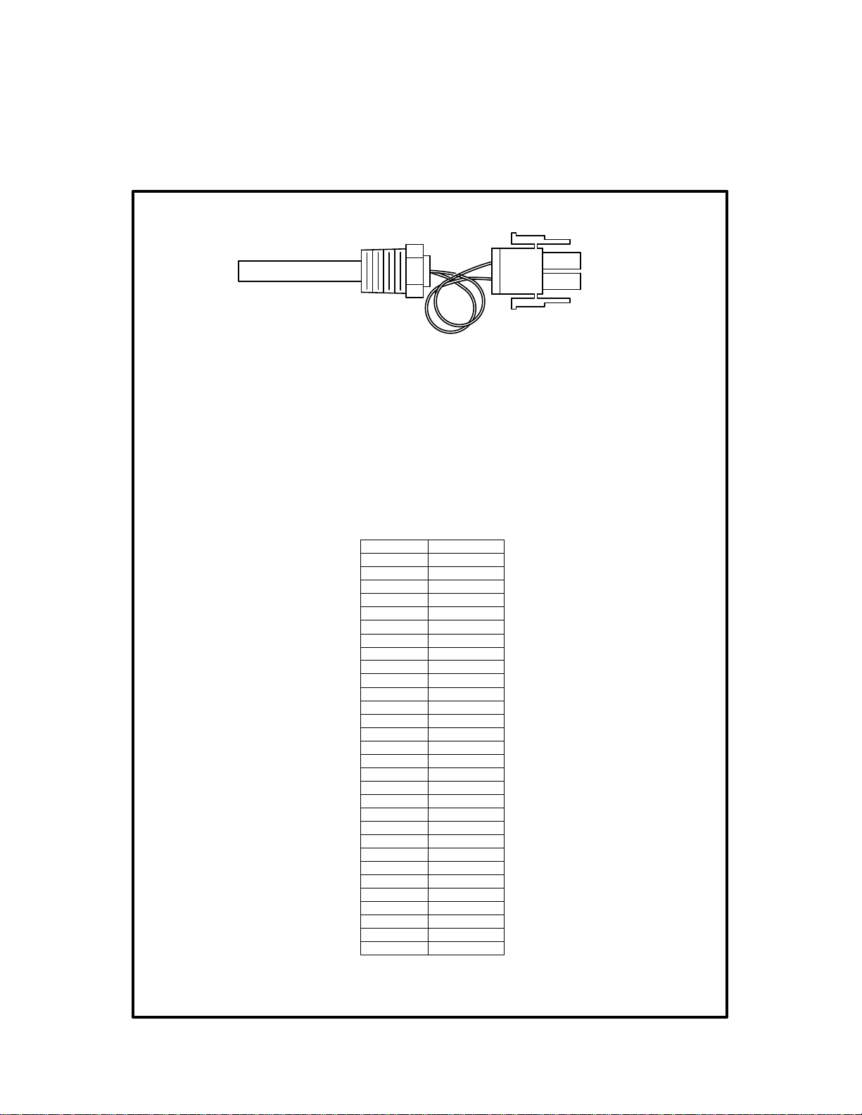
APPENDIX D
TEMPERATURE SENSOR RESISTANCE CHART
(BALCO)
TEMPERATURE SENSOR
AERCO PART NO. 123449
R = RESISTANCE (OHMS) T = TEMPERATURE (°F)
R=.00161T^2+1.961T+854.841
TEMP (°F) RES. (OHMS)
-40 779.0
-30 797.5
-20 816.3
-10 835.4
0 854.8
10 874.6
20 894.7
30 915.1
40 935.9
50 956.9
60 978.3
70 1000.0
80 1022.0
90 1044.4
100 1067.0
110 1090.0
120 1113.3
130 1137.0
140 1160.9
150 1185.2
160 1209.5
170 1234.7
180 1260.0
190 1285.6
200 1311.4
210 1337.7
220 1364.2
230 1391.0
240 1418.2
250 1445.7
D-2
Page 77

APPENDIX E
WIRING DIAGRAMS
APPENDIX E
E-1
Page 78

APPENDIX E
E-2
Page 79
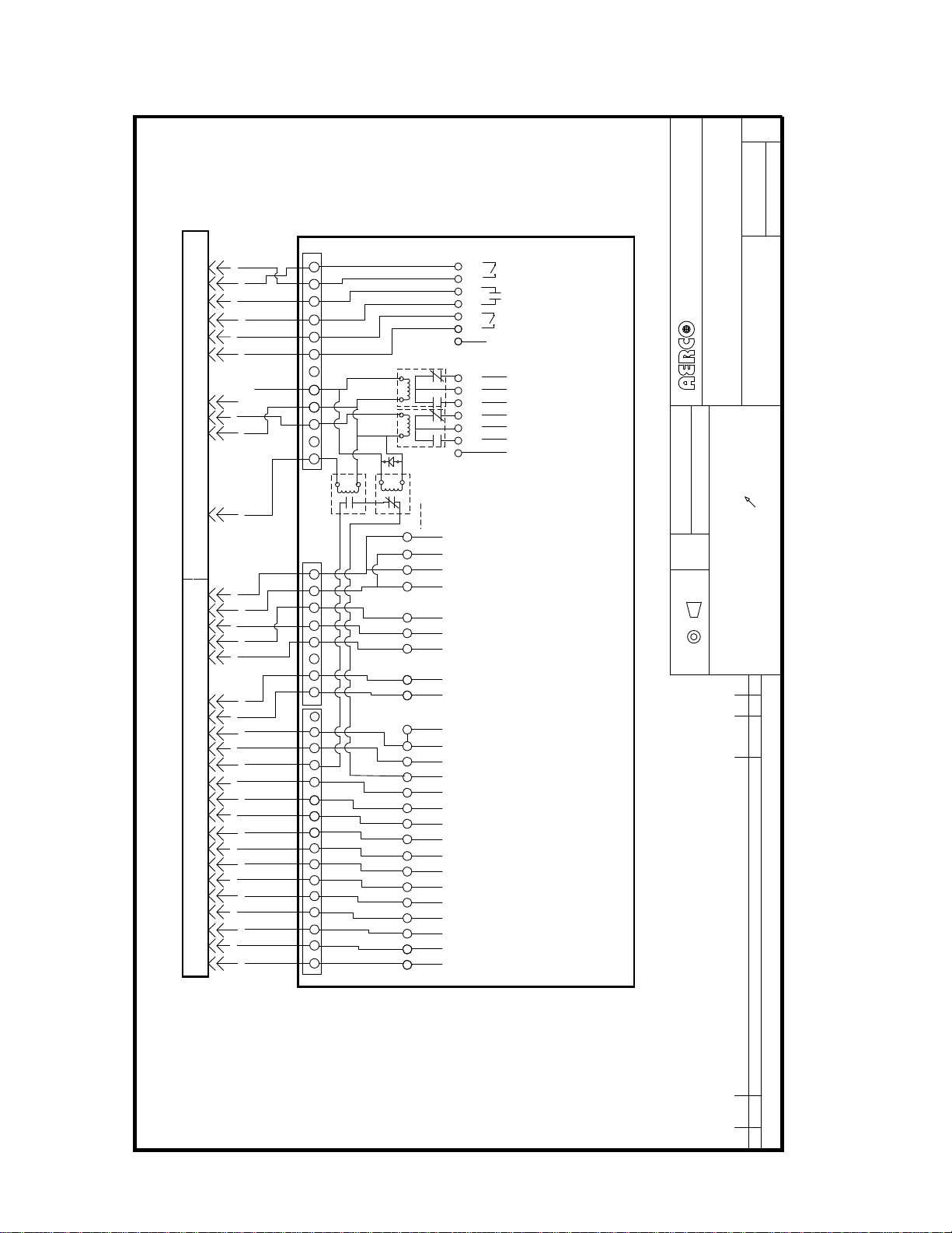
APPENDIX E
C
REVDWG. NO.:
161613
SHEET 2 OF 2
CONTROL BOX CONNECTORS
16-PIN CONNECTOR
24-PIN CONNECTOR
OUT
1
211
212
213
214
215
216
9687 5 4 3 12
219
220
221
LS1
LS2
IN
2
OUT
3
IN
4
OUT
5
IN
6
7
N.C.
1
C
2
N.O.
3
N.C.
1
4
C
5
N.O.
6
7
12 437865 9 10 1211
LS3
LS4
226
4
J3 J2
87654321
253
252 254
3
2
1
3
2
1
2
247
246 250
245 251
244
243
16
1210 11 13 14 1615 17 18 19 2120 22 23 24
241
240 242
854679123 1116 1415 13 12 10
238236
876543211211109131415
1
16
15
14
13
12
11
10
9
8
7
6
235 237 239
234232
233
5
4
3
2
231
1
B
OUT
A
B
IN
A
-
GND
+
-
+
SHIELD
-
+
-
+
-
+
-
+
-
+
REMOTE INTLK
EXHAUST T EMP
DELAYED INTLK
NOT USED
RELAY
FAULT
RELAY
AUX
NOT USED
LONWORKS
RS-485 IN
ANALOG OUT
INTERNATIONAL INC.
159 PARIS AVE, NORTHVALE, N.J.
GAS FIRED BOILER SY STEM
WIRING SCHEMATIC
(KC 1000)
MAT'L SPEC.:
TITLE
061302MD
DATE:CHECKED BY:
.005 TOTAL
DRAWN BY: DATE:
B
ORIGINAL
DWG. SIZE
AS FOLLOWS UNLESS OTHE RWISE SPECIFIED
ALL DIMENSIONS ARE AFT ER FINISH OR PLATING
DIAMETERS ON A COMMON AXIS
PERPENDICULARITY/PARALLELISM/FLATNESS .003 TOTAL
XX ±.015 XXX ± .005 FRACTIONS 1/32± ANGLES ±1°
ALL DIMENSIONS ARE IN INC HES AND ALL TOLERANCES ARE
THIRD ANGLE PROJECTION
INPUT/OUTPUT BOX
CK'D
DATE BY
BMS (PWM) IN
ANALOG IN
SENSOR EXCIT. (12 VDC)
OXYGEN SENSOR IN
FLOW SENSOR IN
CO SENSOR IN
AUX SENSOR IN
SENSOR COMMON IN
OUTDOOR AIR SENSOR IN
REVISIONS
SEE SHEET ONE
J1
THESE DRAWINGS AND/OR SPECIFICATIONS ARE THE PROPERTY OF AERCO INTERNATIONAL, INC. THEY ARE ISSUED IN STRICT CONFIDENCE AND
SHALL NOT BE REPRODUCED, COPIED, OR USED AS THE BASIS FOR MANUFACTURE OR SALE OF APPARATUS WITHOUT PERMISSION OF THE OWNER.
REV ECO
E-3
Page 80

APPENDIX E
E-4
Page 81

16-PIN CONNECTOR
APPENDIX E
A
REV
2
68014
2
SHEET OF
DWG. NO.:
INTERNATIONAL INC.
159 PARIS AVE, NORTHVALE, N.J.
TITLE
120 VAC, 60 HZ
WIRING SCHEMATIC BMK 1.5 LN
MAT'L SPEC.:
211
212
213
214
215
216
9687 54 3 12
219
220
221
12 437865 9 10 1211
LS4
226
LS2 LS1
LS3
J3 J2
87654321
253
252 254
CONTROL BOX CONNECTORS
INPUT/OUTPUT BOX
247
246 250
245 251
244
243
1210 11 13 14 1615 17 18 19 2120 22 23 24
241
240 242
24-PIN CONNECTOR
239
854679123 1116 1415 13 12 10
238236
235 237
234232
233
231
876543211211109131415
J1
E-5
Page 82

APPENDIX E
E-6
Page 83

APPENDIX E
E-7
Page 84

APPENDIX E
C
REVDWG. NO.:
123456123456789
TEMP.
SHELL
SENSOR
161615
133 134
SHEET 1 OF 2
7
145
146
147
148
148
149
9-PIN CONNEC TOR 7-PIN CONN ECTOR
150
151
152
153
123456789101112
161
1
162170
163
164
165
166
CONTROL BOX CONNECTORS
16-PIN CONNEC TOR
168
169 167
171
172173
GNH
147
146145
1K
NC C
151153
10K
3
A
2
STEPPING
150
210
RELAY WITH
152
B
C
200
FUSE
53
5K
201
207
OVERLOAD
120 VAC
204
202
205
205
24 VAC
XFORMER
260
208
MOTOR
FUSE
GND
209
3O
60 HZ
MOTOR
BLOWER
303
T3
95/NC
T3
A2
L3
A1
263
203
263
L3
NEU
230 VAC
300
301
302
T1
T2
T1
T2
MCR
L1
L2
262
261
300
262
L2
206
261
200
GROUND BLOCK
206
L1
AIR/FUEL VALVE
141516 13
INTERNATIONAL INC.
159 PARIS AVE, NORTHVALE, N.J.
2M BTU BOILER SYSTEM
230 VAC, 3 PHASE
WIRING SCHEMATIC
MAT'L SPEC.:
TITLE
061302MD
DATE:CHECKED BY:
.005 TOTAL
DRAWN BY: DATE:
B
ORIGINAL
DWG. SIZE
POWER BOX
AS FOLLOWS UNLESS OTHERWISE SPECIFIED
ALL DIMENSIONS ARE AFTER FINISH OR PLATING
DIAMETERS ON A COMMON AXIS
PERPENDICULARITY/PARALLELISM/FLATNESS .003 TOTAL
XX ±.015 XXX ± .005 FRACTIONS 1/32± ANGLES ±1°
ALL DIMENSIONS ARE IN INCHES AND ALL TOLERANCES ARE
THIRD ANGLE PROJECTION
320
321
{
TO CONTROL BOX
MC
031603
CK'DDATE BY
061302 MD
100703 JM
141
E-8
123456789101112131415
19-PIN CONNEC TOR
190
138
135
136
195 149
140
192
154
155
137
IGNITION
TRANSFOR MER
GND
154
136
209
137
AUTO RESET
MANUAL RESET
202
206
209
208
203
201
204
192
191
190
OVER TEMPERATUR E SWITCHES
210
194
193
195
REVISIONS
RELEASED FOR PRODUCTION
ADDED GROUND WIRES 320 & 321
GENERAL CORRECTIONS TO SCHEMATIC
193
194
141
1819 17 16
191
FIMA
FYP
GKU
THESE DRAWINGS AND/OR SPECIFICATIONS ARE THE PROPERTY OF AERCO INTERNATIONAL, IN C. THEY ARE ISSUED IN STRICT CONFIDENCE AND
SHALL NOT BE REPRODUCED, COPIED, OR USED AS THE BASIS FOR MANUFACTURE OR SALE OF APPARAT US WITHOUT PERMISSION OF THE OWNER.
B
C
REV EC O
Page 85

APPENDIX E
E-9
Page 86

APPENDIX E
E-10
Page 87

APPENDIX E
E-11
Page 88

APPENDIX E
361
364
365
{
362
SSOV
CLOSURE SW.
PROOF OF
SSOV
HIGH GAS PRESS. SW.
LOW GAS PRESS. SW.
}
358
FROM I/O BOX
359
6 PIN CONNECTOR
360
FROM
205
RED
GRN
BLU
BLK
YEL
WHT
352
321
GND
351
SWITCH
POSITION
PURGE
SWITCH
POSITION
IGNITION
IGNITOR
WATER LEVEL PROBE
FLAME ROD
142
BLOWER PROOF SW.
142
E-12
Page 89

APPENDIX E
OUT
1
IN
2
OUT
3
IN
4
OUT
5
IN
6
7
N.C.
1
C
2
N.O.
3
N.C.
4
C
5
N.O.
6
7
4
3
2
1
3
2
1
2
1
16
15
14
13
12
11
10
9
8
7
6
5
4
3
2
1
B
OUT
A
B
IN
A
GND
+
359
359
-
-
+
+
358
358
-
+
-
+
-
+
-
+
-
+
RS-485 IN
ANALOG OUT
ANALOG OUT
SHIELD
BMS (PWM) IN
ANALOG IN
CO SENSOR IN
AUX SENSOR IN
REMOTE INTLK
EXHAUST TEMP
DELAYED INTLK
NOT USED
RELAY
FAULT
RELAY
AUX
NOT USED
LONWORKS
TO VFD
TO VFD
SENSOR EXCIT. (12 VDC)
OXYGEN SENSOR IN
FLOW SENSOR IN
SENSOR COMMON IN
OUTDOOR AIR SENSOR IN
E-13
Page 90

APPENDIX E
D
RE
CONTROL BOX CONNECTORS
123456123456789
TEMP.
SHELL
SENSOR
TEMPERATURE
133 134
TRANSMITTER
1 2 3 4 5 6 7
7
.
AIR
TEMP
SENSOR
145
146
148
147
149
148
9
4
1
G
C
NH
1K
NC
HG
N
145
146
147
201
202
203
150
151
151
152
153
10K
123456789101112
161 153
162
163
164
165
166
167
168
169
16-PIN CONNECTOR19-PIN CONNECTOR 9-PIN CONNECTOR 7-PIN CONNECTOR
170172
171
3
7
1
141516 13
1
A
3
2
150
CONTROL TRANSFORMER
152
B
C
53
5K
MOTOR
STEPPING
AIR/FUEL VALVE
120 VAC
FUSE
4 PIN
CONNECTOR
4
3
2
1
363
FROM 6 PIN
CONNECTOR
X1
460VAC
FUSE
5
1
4
3
1
3
315
314
200
203
2
0
0
2
0
2
1
0
7
2
0
2
FUSE
H4
4 AMPS
H3
XF
X2
319
4
0
2
XFMR
24 VAC
8
0
2
9
0
2
317
H2
H1
316
5
0
2
MOTOR
BLOWER
303
301
302
300
UWV
PEPE
L3
L2
L1
T1T2 T4T3 T6T5
VFD
INTERNATIONAL INC.
159 PARIS AVE, NORTHVALE, N.J.
TITLE
330
331
333
332
205
95/NC
A2
120 VAC
RELAY WITH
OVERLOAD
A1
263
210
142
316
260
GND
T1
T3
T2
T1
T2
T3
L3
262
317
263
262
L3
O
3
60 HZ
330
MCR
POWER BOX
319
L1
L2
261
366
GND BLOCK
260
261
320
321
6
0
2
L2
L1
350
460VAC
2
1
68006
SHEET OF
DWG. NO.: V
460 VAC, 3 PHASE
WIRING SCHEMATIC BMK 3.0 LN
MAT'L SPEC.:
E-14
141
TO CONTROL BOX {
123456789
190
140 195
138
192
1011
136 135
155 154
12131415
193
194 137
1819 17 16
141
191
TRANSFORMER
IGNITION
136
AUTO RESET
209
2
3
0
0
201
2
2
4
0
2
1
0
9
9
1
1
6 PIN CONNECTOR
206
2
9
1
0
8
9
1
0
0
2
2
2
5
4
3
9
9
9
1
1
1
154
137
MANUAL RESET
OVER TEMPERATURE SWITCHES
365
TO TEMP.
R
E
T
T
I
M
S
N
A
R
T
.
362
360
P
M
E
T
O
T
TO VFD
TRANSMITTER
SOLENOID
Page 91

APPENDIX E
OUT
1
IN
2
OUT
3
IN
4
OUT
5
IN
6
7
N.C.
1
C
2
N.O.
3
N.C.
4
C
5
N.O.
6
7
4
3
2
1
3
2
1
2
1
16
15
14
13
12
11
10
9
8
7
6
5
4
3
2
1
B
OUT
A
B
IN
A
GND
+
359
359
-
-
+
+
358
358
-
+
-
+
-
+
-
+
-
+
RS-485 IN
ANALOG OUT
ANALOG OUT
SHIELD
BMS (PWM) IN
ANALOG IN
CO SENSOR IN
AUX SENSOR IN
REMOTE INTLK
EXHAUST TEMP
DELAYED INTLK
NOT USED
RELAY
FAULT
RELAY
AUX
NOT USED
LONWORKS
TO VFD
TO VFD
SENSOR EXCIT. (12 VDC)
OXYGEN SENSOR IN
FLOW SENSOR IN
SENSOR COMMON IN
OUTDOOR AIR SENSOR IN
E-15
Page 92

Page 93

APPENDIX F
APPENDIX F
C-MORE CONTROL PANEL
DIP SWITCH SETTINGS
F-1
Page 94

APPENDIX F
APPENDIX F - C-MORE CONTROL PANEL DIP SWITCHES
F-1. INTRODUCTION
The PMC (Primary Micro-Controller) Board in the C-More Control Panel Assembly contains two 4-position
DIP switches (S1, S2) as shown in Figure F-1. The functions of these DIP switches are as follows:
• 4-Position DIP switch S1 (Detail “A”) is used to select either current or voltage as the Remote
Signal Source when operating in the Remote Setpoint or Direct Drive Mode. The factory default
for this switch is current (CURR).
• 4-Position DIP switch S2 (Detail “B”) is used to enable a terminating (TERM) resistor and bias
(BIAS1, BIAS2) when it is the last
setting for this switches is OFF. Refer to Modbus Communication Manual GF-114 for additional
information on setting these switches
The following procedures provide the instructions necessary to access the DIP switches on the PMC
Board and select the required settings.
F-2. ACCESSING AND SETTING PMC BOARD DIP SWITCHES
The following procedures provide the instructions necessary to access the DIP switches on the PMC
Board and select the required settings.
unit on a RS485 (Modbus) Network chain. The factory default
1. Remove power from the C-More Control Panel.
2. Loosen and remove the four (4) screws securing the front panel assembly to the chassis as shown in
Figure F-2. The horizontal panel configuration shown in Figure F-2 is for a KC1000 unit. Benchmark
units utilize a vertical panel layout, however removal is identical for both configurations.
3. Carefully separate the panel from the chassis. Use care to avoid applying undue stress to the ribbon
cable connected between the back of the panel and the chassis-mounted printed circuit boards.
CAUTION
The C-More Controller Printed Circuit Boards contain electronic components that
are sensitive to electrostatic discharge (ESD). Prior to performing the following
steps, put on an anti-static wrist strap and connect the clip lead to earth ground.
Failure to observe this precaution may result in permanent damage to on-board
ESD-sensitive components.
4. Put on an anti-static wrist strap and attach the clip lead to earth ground.
5. From the back of the Panel Assembly (Figure F-3), locate the 4-position Curr/Volt DIP switch S1
shown in Figure F-1 (Detail “A”) on the PMC Board. All 4 positions of switch S1 should currently be
set to the ON (Up) position which is the factory default setting of current (CURR). If your installation
will utilize voltage as the Remote Signal source, set all 4 positions of S1 to the OFF (Down) position
to select voltage (VOLT).
6. If the C-More Control Panel is the last
the RS485 4-position DIP switch S2 shown in Figure F-1 (Detail “B”). Refer to GF-114 Modbus
Communication Manual prior to changing the switch setting.
unit in a RS485 Network chain, it will be necessary to activate
7. After the DIP switches have been set, reposition the Front Panel Assembly on the chassis and secure
it in place with the four screws.
8. This completes the procedure for setting the DIP switches. Return the unit to service use.
F-2
Page 95

APPENDIX F
RIBBON CABLE
CONNECTOR (J1)
SEE DETAIL “B”
J1
C38
U8
C7
C64
C5
C6
R74
C2
C52
C50
JP2
C57
R76
C51
C53
C56
R71
R73
R72
Y1
CR1
C1
U1
C4
C3
CBS1
RS485
R49
TERM
BIAS1
BIAS2
S2
R48
C36
R44
R45
J2
R46
R81
C37
J4
R75
R53
R1
U2
U21
R70
U17
R69
R68
R67
C40
R50
C39
R47
R54
R55
R52
U7
U6
Y2
HB
DS3
R77
C54
RS485
DS2
R51
RX
J3
U18
TX
DS1
C11
C13
R10
C12
R8
C10
R7
U16
S1
R11
U3
B1
C63
BH1
C55
C58
C61
R6
R9
C48
R5
U19
U15
CURR/VOLT
ON = CURR
OFF = VOLT
R2
R3
R12
C60
C59
C49
C65
R80
C19
U20
DS5DS4
TX
RS232
C8
R4
C9
C15
R13
C14
R58
C16
R66
RX
CBS3
R62
C62
R29
R14
C43
R65
U14
R78
R79
C30
R37
R34
C27
C45
U11
R38
R36
R35
R33
R16
Q2
C25
R30
R31
C18
SEE DETAIL “A”
Q1
CBS2
R32
R17
R18
R15
C46
CBS4
C66
R56
R57
C28
R64
C34
U10
U13
U5
U4
C23
C26
C41
C35
C32
C20
C44
C29
C31
C47
CR2
C22
R27
C17
C42
R60
R26
R28
U9
U12
R59
R41
R25
C24
R22
C21
R23
R21
C33
R42
R43
R40
R24
R63
R61
R39
R20
R19
THE BIAS2, TERM AND BIAS1
DIP SWITCHES ARE USED ONLY
WHEN THIS IS THE LAST
CONNECTED AT THE END OF
A RS485 (MODBUS) NETWORK
CHAIN.
ON (UP) = ENABLED
OFF (DOWN) = DISABLED
REFER TO GF-114 BEFORE
ACTIVATING ANY OF THESE
SWITCHES.
UNIT
CURR/VOLT
S1
ON = CURR
OFF = VOLT
THESE DIP SWITCHES ARE USED
TO SET EITHER CURRENT (CURR )
OR VOLTAGE (VOLT) AS THE
REMOTE SIGNAL INPUT SOURCE.
ON (UP) = CURRENT
OFF (DOWN) = VOLTAGE
RS485
TERM
BIAS2
S2
BIAS1
Figure F-1. C-More Control Panel PMC Board
F-3
Page 96

APPENDIX F
Figure F-2. C-More Control Panel Front View – KC1000
F-4
Page 97

APPENDIX F
RIBBON
CABLE
CONTROL PANEL REAR VIEW – KC1000
RS485
DIP SW.
J1
C38
U8
R1
C7
C64
C5
C6
C56
CR1
R71
R73
C1
R72
C2
R70
R76
C51
C53
Y1
U1
C52
C57
C4
R74
C3
C50
CBS1
RS485
R49
R48
R53
C36
U2
R44
U21
U17
R69
R68
R67
CBS3
R54
R55
C40
R50
R52
U7
C39
S2
R47
U6
R46
R81
C37
R45
Y2
J4
HB
DS3
C54
R75
PMC
BOARD
J2
CURR/VOLT
DIP SW.
CURR/VOLT
S1
ON = CURR
RS485
OFF = VOLT
R11
C65
R2
R5
R80
R8
R58
C8
C10
R62
R3
R6
R4
R7
C9
C11
U3
R51
C13
C15
R13
R10
C12
C14
R9
R12
J3
BH1
B1
U16
R77
U18
C16
C63
C19
U19
C55
U15
R66
C58
U20
C61
C59
C60 C62
DS5DS4
C49
C48
RS232
Q1
CBS2
R56
CR2
Q2
R57
R63
C66
R61
C41
R59
R64
C42
C43
R65
R60
U5
C30
C33
C35
R37
R42
C32
R38
R43
R36
R41
C29
R40
R35
C31
R39
R34
C28
C23
C22
R24
C25
R29
R25
R30
R26
R31
R28
R33
C26
C27
C24
R32
R27
R14
R17
U4
R22
C34
C18
C21
R23
C20
R18
R21
R20
R16
R19
C17
R15
C45
C44
U10
U11
U9
U13
U14
U12
R78
R79
C47
C46
CBS4
RIBBON
CABLE
C5
CR1
C1
U1
C4
C3
J1
C38
U8
R1
C7
C64
C6
C56
R71
R73
R72
C2
R76
C51
C53
Y1
C52
C57
R74
C50
RS485
DIP SW.
CBS1
RS485
R55
R49
C40
R50
U7
C39
S2
R47
U6
R48
R46
R53
R81
C36
C37
U2
R45
R44
J4
HB
DS3
U21
C54
R75
R70
U17
R69
R68
R67
J2
CBS3
S1
RS485
R11
R54
R5
R8
R52
C10
R6
R7
C11
U3
R51
C13
R10
C12
R9
J3
BH1
B1
Y2
U16
R77
C63
U19
U18
PMC
C55
U15
BOARD
C58
C61
C48
CURR/VOLT
DIP SW.
Q1
CBS2
CURR/VOLT
ON = CURR
R56
OFF = VOLT
R2
R3
R12
C60
C59
DS4
C49
RS232
CR2
C65
Q2
R57
C66
R80
R58
C8
C41
R59
R62
R64
R4
C9
C15
R13
C14
C19
U20
DS5
C42
C43
R65
R60
U5
C30
C35
R37
C32
R38
R36
C29
R35
C31
R34
C28
C23
C22
C25
R29
R25
R30
R26
R31
R28
R33
C26
C27
R32
R27
R14
R17
U4
R22
C16
C34
C18
C21
R23
C20
R18
R21
R16
C17
R15
C45
C44
U10
U11
U9
R66
U13
U14
U12
C62
R78
R79
C47
C46
CBS4
R63
R61
C33
R42
R43
R41
R40
R39
R24
C24
R20
R19
CONTROL PANEL REAR VIEW – BENCHMARK
Figure F-3. C-More Control Panel Rear Views
F-5
Page 98

 Loading...