

Page 1

AERCO International, Inc. • 100 Oritani Dr. • Blauvelt, New York 10913 • Phone: 800-526-0288
TID-0006_0B
TECHNICAL INSTRUCTIONS
Created: 08/27/2012
Hardware Procedure:
Applies to:
the installation and maintenance of the
AERCO 4-Port Buffer Tank
AERCO Buffer Tank
Installation and
Maintenance
Any applicable water heater/boiler piping
system arrangement.
Description of Document:
This Technical Instruction Document
provides the instructions necessary for
AERCO buffer tanks in AERCO and nonAERCO systems.
Page 2

AERCO International, Inc. • 100 Oritani Dr. • Blauvelt, New York 10913 • Phone: 800-526-0288
AERCO Buffer Tank Installation and Maintenance
Technical Instruction Document
TID-0006_0B
Technical Support:
1-800-526-0288
www.aerco.com
(Mon–Fri, 8am-5pm EST)
Disclaimer
The information contained in this manual is subject to change without notice from
AERCO International, Inc. AERCO makes no warranty of any kind with respect to this
material, including, but not limited to, implied warranties of merchantability and fitness for
a particular application. AERCO International is not liable for errors appearing in this
manual. Nor for incidental or consequential damages occurring in connection with the
furnishing, performance, or use of this material.
VD2: 08/27/12 Page 2 of 14
Page 3

AERCO International, Inc. • 100 Oritani Dr. • Blauvelt, New York 10913 • Phone: 800-526-0288
AERCO Buffer Tank Installation and Maintenance
Technical Instruction Document
TID-0006_0B
TABLE OF CONTENTS
1. INTRODUCTION ................................................................................ 4
2. BUFFER TANK TYPES ...................................................................... 4
3. BUFFER TANK INSTALLATION ........................................................ 6
4. BUFFER TANK FIELD PIPING ........................................................... 7
AERCO’S LIMITED BUFFER TANK WARRANTY ...................................... 13
VD2: 08/27/12 Page 3 of 14
Page 4

AERCO International, Inc. • 100 Oritani Dr. • Blauvelt, New York 10913 • Phone: 800-526-0288
AERCO Buffer Tank Installation and Maintenance
Technical Instruction Document
TID-0006_0B
1. INTRODUCTION
AERCO buffer tanks are ASME certified pressure vessels designed for use with high efficiency,
low volume systems that incorporate low-mass condensing boilers. Hydronic heating systems
featuring several low BTU heating loads (calling at different times) very often operate below the
design load conditions, which causes short-cycling and so may reduce system efficiency and
equipment life. A buffer tank may be added to such a system to add thermal mass, dampen fast
transitions and minimize boiler cycling that occurs during zero or low domestic load conditions,
thus reducing short cycling.
IMORTANT NOTICE!
Incorrect installation can cause rapid failure of water tanks due to
electrolysis. It is vital that this risk is reduced by the use of
dielectric connections, and isolation of the tank supports.
Installers must be aware of correct procedures. For assistance
please call: 1-800-526-0288.
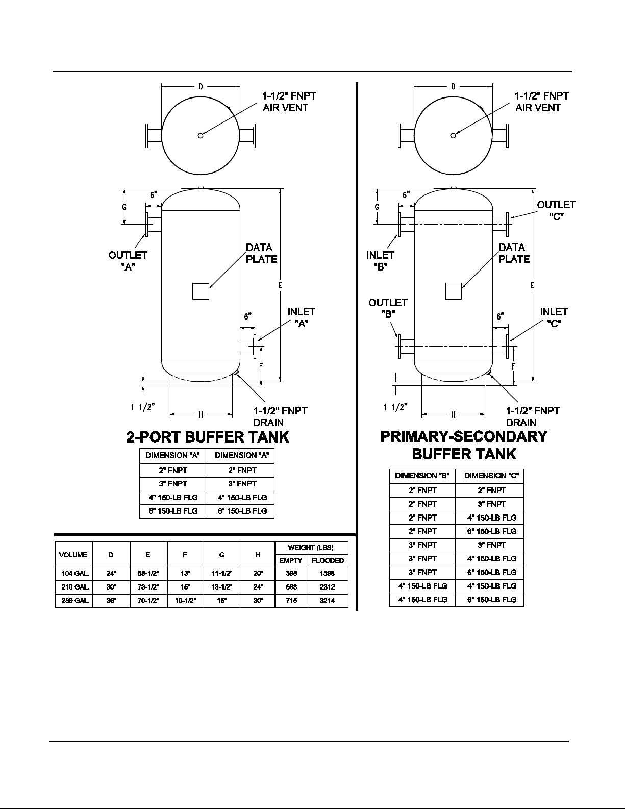
2. BUFFER TANK TYPES
The AERCO buffer tanks come as either a 2-port or a 4-port primary-secondary tank and in the
following three sizes:
• 104 gallons
• 210 gallons
• 289 gallons
See Figure 1 for port designations and dimensions.
VD2: 08/27/12 Page 4 of 14
Page 5
AERCO International, Inc. • 100 Oritani Dr. • Blauvelt, New York 10913 • Phone: 800-526-0288
AERCO Buffer Tank Installation and Maintenance
Technical Instruction Document
TID-0006_0B
Figure 1: AERCO Buffer Tanks – Port Designations
VD2: 08/27/12 Page 5 of 14
Page 6

AERCO International, Inc. • 100 Oritani Dr. • Blauvelt, New York 10913 • Phone: 800-526-0288
AERCO Buffer Tank Installation and Maintenance
Technical Instruction Document
TID-0006_0B
3. BUFFER TANK INSTALLATION
Consult your local building codes for water heater regulations and make sure that you acquire
any necessary permits.
NOTE FOR MASSACHUSETTS INSTALLATIONS: Storage tank installations within the
Commonwealth of Massachusetts must conform to 248 CMR 10.00.
Refer to the user manual for the water heater being used to ascertain any special requirements
for your installation and proceed as follows:
Installing the Buffer Tank
1. Clear the area around installation site of all flammable and combustible materials.
2. Switch off the boiler/water heater and allow the system to cool for four hours.
3. Isolate the electrical supply to the existing boiler/water heater by switching off the
electricity at the mains supply point.
4. Turn off the cold water supply to the existing heating system and any other heating
appliance.
5. Turn off the main gas supply valve downstream from the boiler/water heater.
6. If you are replacing an existing buffer tank, be sure to drain and disassemble it according
to the manufacturer’s instructions.
7. Install drain fittings at bottom connection before setting the tank permanently.
8. Place the new tank into position and line it up to be flush with existing plumbing
connections. Connect the buffer tank to the plumbing using appropriate techniques.
9. Ensure ground wires to the boiler/water heater are connected.
10. Turn on mains electric power and mains gas upstream from the boiler/water heater.
11. Turn on the cold water supply to the tank, followed by the main water supply to the
system. Allow the tank to fill with cold water. Open the bleeder valve on the top of the
tank to vent air from the tank so it fills completely.
12. After installation, fill the system and run at operating temperature for at least one day in
a closed loop mode, then drain system, and re-fill.
NOTE
The tank should be installed in such a manner that should the tank
or any connections leak, the resulting flow of water will not cause
damage.
VD2: 08/27/12 Page 6 of 14
Page 7

AERCO International, Inc. • 100 Oritani Dr. • Blauvelt, New York 10913 • Phone: 800-526-0288
AERCO Buffer Tank Installation and Maintenance
Technical Instruction Document
TID-0006_0B
4. BUFFER TANK FIELD PIPING
An AERCO boiler system should be piped in one of four arrangements, depending on your
system design requirements and the boiler specified. Benchmark boilers can be installed with a
2-port buffer tank. Modulex boilers should be installed with a 4-port buffer tank. For illustration
purposes, AERCO SmartPlate water heaters are depicted in the piping diagrams presented in
these instructions.
Select the appropriate piping diagrams for your application from the following drawings:
NOTE
Each AERCO boiler requires a minimum flow when used in DHW
combination systems – see figures below for specific minimum
flow requirements for each boiler model.
• Figure 2 shows the buffer tank and SmartPlate heaters piped as a zone with the Benchmark
boilers and the heating system.
• Figure 3 shows the buffer tank and SmartPlate heaters, piped as a zone with the
Benchmark boilers and the heating system, and a separate zone, or summer pump. In this
arrangement the system pump supplies the buffer tank/SmartPlate zone during the heating
season. When the heating season ends, the system pump can be shut down and the zone
will be serviced by the separate summer pump to conserve energy.
• Figure 4 shows the buffer tank and SmartPlate heaters piped with Benchmark boilers
dedicated solely to domestic water heating.
• Figure 5 shows the 4-port buffer tank and SmartPlate heaters piped with Modulex boilers.
The location of connections on the 4-port buffer tank, and natural stratification will ensure
that the hot outlet water for the boilers will pass through to the system and the colder return
water will pass through back to the boilers and allow condensing.
• A non-AERCO low mass boiler system should be piped as shown in Figure 6. In this
illustration, SmartPlate water heaters and a 4-port buffer tank are piped as a zone of the
heating system.
IMPORTANT!
The piping schematics shown in these installation procedures
illustrate only the piping between the water heater and the
AERCO tank. SEE THE APPROPRIATE WATER HEATER
OPERATIONS AND MAINTENANCE MANUAL FOR COMPLETE
WATER HEATER INSTALLATION INSTRUCTIONS.
VD2: 08/27/12 Page 7 of 14
Page 8

AERCO International, Inc. • 100 Oritani Dr. • Blauvelt, New York 10913 • Phone: 800-526-0288
AERCO Buffer Tank Installation and Maintenance
Technical Instruction Document
TID-0006_0B
Figure 2: 2-Port Buffer Tank and SmartPlate Heaters Piped as a Zone with Benchmark
Boilers and Heating System
VD2: 08/27/12 Page 8 of 14
Page 9

AERCO International, Inc. • 100 Oritani Dr. • Blauvelt, New York 10913 • Phone: 800-526-0288
AERCO Buffer Tank Installation and Maintenance
Technical Instruction Document
TID-0006_0B
Figure 3: 2-Port Buffer Tank and SmartPlate Heaters Piped as a Zone with Benchmark Boilers and Heating
System with a Separate Zone/Summer Pump
VD2: 08/27/12 Page 9 of 14
Page 10

AERCO International, Inc. • 100 Oritani Dr. • Blauvelt, New York 10913 • Phone: 800-526-0288
AERCO Buffer Tank Installation and Maintenance
Technical Instruction Document
TID-0006_0B
Figure 4: 2-Port Buffer Tank and SmartPlate Heaters with Benchmark Boilers Dedicated to Domestic Water
Heating
VD2: 08/27/12 Page 10 of 14
Page 11

AERCO International, Inc. • 100 Oritani Dr. • Blauvelt, New York 10913 • Phone: 800-526-0288
AERCO Buffer Tank Installation and Maintenance
Technical Instruction Document
TID-0006_0B
Figure 5: 4-Port Buffer Tank and SmartPlate Heaters with Modulex Boilers
VD2: 08/27/12 Page 11 of 14
Page 12

AERCO International, Inc. • 100 Oritani Dr. • Blauvelt, New York 10913 • Phone: 800-526-0288
AERCO Buffer Tank Installation and Maintenance
Technical Instruction Document
TID-0006_0B
Figure 6: SmartPlate Heaters with Boiler Side 4-Port Buffer Tank as a Zone
VD2: 08/27/12 Page 12 of 14
Page 13

AERCO International, Inc. • 100 Oritani Dr. • Blauvelt, New York 10913 • Phone: 800-526-0288
AERCO Buffer Tank Installation and Maintenance
Technical Instruction Document
TID-0006_0B
AERCO’S LIMITED BUFFER TANK WARRANTY
AERCO International, Inc. warrants that its buffer tank is of the kind and quality quoted on and
warrants it to be free of defective material and /or workmanship only. This warranty is not
applicable to operational failures, gasket leaks or malfunctions caused by improper application,
installation and/or maintenance. Warranty not applicable if electrolysis condition or abnormal
water condition exists.
Any claim for adjustment under this Limited Warranty must be made within the Warranty period
(see below). AERCO shall replace or repair at its option, all parts which upon examination by
AERCO prove to be defective material and/or workmanship within the above Limited Warranty.
If required by AERCO, parts which are claimed defective must be promptly delivered to
AERCO facility, transportation charges prepaid. No material may be returned (unused or
warranty), without prior approval. All returned goods must have a copy of original invoice.
AERCO will not however, accept any claims for labor costs incurred by the user in removing or
reinstalling a product and/or part thereof. This warranty does not apply if the defect is due to
failure to use the product for its intended purpose, the result of an accident, abuse, misuse or
unauthorized alteration, or because the product was not installed and maintained in accordance
with standard plumbing practices. However, any and all costs required to ship, disassemble,
remove, reassemble, reinstall a tank, shall not be borne by AERCO and IS NOT COVERED
under this warranty. IN NO EVENT SHALL AERCO BE LIABLE FOR INCIDENTAL OR
CONSEQUENTIAL DAMAGES. Some states do not allow the exclusion or limitation of
incidental or consequential damages, so the above limitation or exclusion may not apply to you.
Any implied warranties which the user may have including merchantability and fitness for a
particular purpose, shall not extend beyond the period (see below) from date of manufacture of
any product. Some states do not allow limitations on how long an implied warranty lasts, so the
above limitation may not apply to you.
PERIOD OF LIMITED WARRANTY
The AERCO Buffer Tank is warranted for 1 YEAR FROM DATE OF SHIPMENT when used
on applications for which it is intended.
VD2: 08/27/12 Page 13 of 14
Page 14

AERCO International, Inc. • 100 Oritani Dr. • Blauvelt, New York 10913 • Phone: 800-526-0288
AERCO Buffer Tank Installation and Maintenance
Technical Instruction Document
TID-0006_0B
© AERCO International, Inc., 2011
VD2: 08/27/12 Page 14 of 14
 Loading...