

Page 1
GF-124
Instruction
No
AERCO INTERNATIONAL, Inc., Northvale, New Jersey, 07647 USA
.
Installation, Operation
& Maintenance Instructions
BMS II BOILER
MANAGEMENT
SYSTEM
JANUARY 19, 2011
Page 2

Telephone Support
Direct to AERCO Technical Support
(8 to 5 pm EST, Monday through Friday):
1-800-526-0288
AERCO International, Inc.
159 Paris Avenue
Northvale, NJ 07647-0128
www.aerco,com
© AERCO International, Inc., 2011
The information contained in this installation,
operation and mainte nance manual is s ubject to
change without notice from AERCO
International, Inc.
AERCO makes no warranty of any kind with
respect to this material, inc luding but not limited
to implied warranties of merchantability and
fitness for a particular application. AERCO
International is not liable for er rors appearing in
this manual. Nor for incide ntal or consequential
damages occurring in connection with the
furnishing, perform ance, or use of this material.
Page 3

FOREWORD
Phrase, Abbreviation or
A (Amp)
Ampere
ADDR
Address
ALRM
Alarm
AUX
Auxiliary
below)
Baud Rate
Symbol rate, or simply the number of distinct symbol changes (signaling
each symbol is 1 bit long.
BCM
Boiler Control Module used with AERCO Modulex Series Boilers
BLR
Boiler
BMS II
AERCO Boiler Management System, Second Generation
BND
Band
Bias Resistors
A pair of resistors used to force the communication line to a definite logic
state so that noise is not picked up as invalid data during communication.
BLDG (Bldg)
Building
C-More Controller
(or Control Box)
A control system developed by AERCO and currently used in all Benchmark
and KC1000 Series product lines.
CNTL
Control
DIP
Dual In-Line Package
DYN
Dynamic
EMS
Energy Management System; often used interchangeabl y with BAS
Ethernet
A computer networking technology for Local Area Networks (LANs)
FDX
Full-Duplex
FLT
Fault
GND
Ground
HDR
Header
HDX
Half-Duplex
Foreword
The Model 5R5-384 B oiler Management S ystem II (BMS II) is the l atest model of AERCO’s BMS lin e of
flexible boiler plant contr ollers.. The system can control a boil er plant comprised of AERCO Benc hmark
Series, Modulex Series or KC10 00 Boilers. The BMS II can stage an d coordinate the operation of up to
32 AERCO Boilers with maximized efficiency. With individual boilers with turn-down ratios as high as
20:1, a 5-boiler plant can deli ver a system turn-down ratio of 100: 1 when the bo il e r s ar e s taged to opera te
sequentially.
The BMS II is fully compatible with a wide array of Building Automation Systems (BAS) or Energy
Management System s (EMS) utilizing M odbus Pr otocol. T he BAS or EMS com municates with the BMS II
utilizing a RS232 i nterfac e. If the BAS or EMS does not c ontain a RS23 2 port , the BMS II can be order ed
with a RS485-to-RS232 Converter which can be easily installed within the BMS II’ wiring compartment.
PHRASES, ABBREVIATIONS & ACRONYMS
The phrases, abbreviations and acronyms used in this document are listed in the following table
Phrases, Abbreviations and Acronyms
Acronym
BAS Building Automation System, often used interchangeably with EMS (see
events) transmitted per second. It is not equal to bits per second, unless
Meaning
i
Page 4

FOREWORD
Hex
Hexadecimal Number (0 - 9, A - F)
Hz
Hertz (Cycles Per Second)
INTLK
Interlock
I/O
Input/Output
I/O Box
Input/Output (I/O) Box currently used on all Benchmark and KC Series
products
IP
Internet Protocol
ISO
Isolated
LSB
Least Significant Byte
LSD
Least Significant Digit
MA (mA)
Milliampere
MAX (Max)
Maximum
MIN (Min)
Minimum
Modbus®
A serial, half-duplex data transmission protocol developed by AEG Modicon
MSB
Most Significant Byte
MSD
Most Significan t Digit
MS/TP
Master-Slave/Token-Passing (usually over RS485 networks)
OFFS
Offset
OUTD
Outdoor
PTP
Point-to-Point (usually over RS232 networks)
REF (Ref)
Reference
Response Time
The maximum amount of time allowed to receive a response to a request
(or EIA-232)
RS232 Standard
RS422
(or EIA-422)
A standard for serial, full-duplex (FDX) transmission of data based on the
RS422 Standard
(or EIA-485)
RS485 Standard
RTN
Return
RTU
Remote Terminal Unit
SEN
Sensor
SETPT (Setpt)
Setpoint Temperature
SHLD (Shld)
Shield
SLTA
Serial LonTalk Adapter
SYS
System
TEMP (Temp)
Temperature
Terminating Resistor
A resistor placed at each end of a daisy-chain or multi-drop network in order
to prevent reflections that may cause invalid data in the communication
VAC
Volts, Alternating Current
VDC
Volts, Direct Current
VFD
Vacuum Fluorescent Display
Phrases, Abbreviations and Acronyms - Continued
Phrase, Abbreviation or
Acronym
Meaning
RS232
RS485
A standard for serial, full-duplex (FDX) transmission of data based on the
A standard for serial, half-duplex (HDX) transmission of data based on the
ii
Page 5

CONTENTS
GF-124 – BMS II BOILER MANAGEMENT SYSTE M
Operating & Maintenance Instructions
TABLE OF CONTENTS
CHAPTER 1 - GENERAL INFORMATION .................................................................................................... 1-1
1.1 SAFETY PRECAUTIONS & WARNINGS ................................................................................................... 1-1
1.2 INTRODUCTION ........................................................................................................................................... 1-1
1.3 BMS II GENERAL description ....................................................................................................................... 1-1
1.4 BMS II FEATURES ........................................................................................................................................ 1-2
Simplified Installation and Set-Up .................................................................................................................... 1-2
User-Friendly Control System Interface ............................................................................................................ 1-2
Retention of Menu Option Settings ................................................................................................................... 1-3
Application Flexibility ....................................................................................................................................... 1-3
Sequential or Parallel Operation ........................................................................................................................ 1-3
Accuracy ............................................................................................................................................................ 1-3
Bumpless Transfer ............................................................................................................................................. 1-3
Fault Alarm Surveillance ................................................................................................................................... 1-3
BMS II Programming Via RS232 Port. ............................................................................................................. 1-3
CHAPTER 2 - INSTALLATION ...................................................................................................................... 2-1
2.1 INTRODUCTION ........................................................................................................................................... 2-1
2.2 SITE SELECTION AND MOUNTING .......................................................................................................... 2-1
Mounting the BMS ............................................................................................................................................ 2-1
2.3 GENERAL WIRING REQUIREMENTS ....................................................................................................... 2-2
2.4 POWER WIRING ........................................................................................................................................... 2-3
2.5 SENSOR INSTALLATION AND WIRING ................................................................................................... 2-5
Header Sensor .................................................................................................................................................... 2-5
Return Sensor .................................................................................................................................................... 2-5
Outdoor Air Sensor ............................................................................................................................................ 2-6
2.6 RS485 (MODBUS) WIRING AT THE BMS II .............................................................................................. 2-8
BMS II Bias Switches & Loop Te rmination Resistors ...................................................................................... 2-8
2.7 RS485 (MODBUS) WIRING, BIAS & TERMINATION AT AERCO BOILERS ........................................ 2-9
RS485 Wiring, Termination& Bias for Benchmark Series and KC1000 Boilers .............................................. 2-9
RS485 Wiring for Modulex Series Boilers ...................................................................................................... 2-15
2.8 SAMPLE RS485 (MODBUS) NETWORK DIAGRAMS ............................................................................ 2-15
2.9 RS232 WIRING AT THE BMS II ................................................................................................................ 2-17
2.10 INTERLOCK WIRING ............................................................................................................................... 2-18
Interlock 1 (INT 1) Wiring .............................................................................................................................. 2-18
Interlock 2 (INT 2) Wiring .............................................................................................................................. 2-18
2.11 SET BACK WIRING .................................................................................................................................. 2-18
2.12 RELAY WIRING ........................................................................................................................................ 2-18
System Start Relay ........................................................................................................................................... 2-19
Fault Alarm Relay ........................................................................................................................................... 2-19
Auxiliary Relay................................................................................................................................................ 2-19
2.13 4 – 20 mA WIRING .................................................................................................................................... 2-19
CHAPTER 3 - OPERATION ............................................................................................................................. 3-1
3.1 INTRODUCTION ........................................................................................................................................... 3-1
3.2 FRONT PANEL OPERATING CONTROLS AND DISPLAYS ................................................................... 3-1
3.3 BMS II MENU STRUCTURE ........................................................................................................................ 3-3
Menu Processing Procedure .............................................................................................................................. 3-3
3.4 OPERATING MENU ...................................................................................................................................... 3-5
HEADER TEMP and PERCENT OF LOAD .................................................................................................... 3-5
HEADER SETPOINT ....................................................................................................................................... 3-5
OUTSIDE AIR TEMP ....................................................................................................................................... 3-5
I/O STATUS ...................................................................................................................................................... 3-6
RETURN TEMP ................................................................................................................................................ 3-6
iii
Page 6

CONTENTS
TABLE OF CONTENTS (cont.)
3.5 SETUP MENU ................................................................................................................................................ 3-6
ENTER PASSWORD ........................................................................................................................................ 3-6
Date and Time Menu Options ............................................................................................................................ 3-6
3.6 RS232 MENU .................................................................................................................................................. 3-7
RS232 MODE.................................................................................................................................................... 3-7
RS232 BAUD RATE ......................................................................................................................................... 3-7
MODBUS ADDRESS ....................................................................................................................................... 3-7
NETWORK TIMEOUT .................................................................................................................................... 3-7
MODBUS PASS THRU .................................................................................................................................... 3-7
3.7 RS485 MENU .................................................................................................................................................. 3-7
RS485 BAUD RATE ......................................................................................................................................... 3-8
MIN SLAVE ADDR ......................................................................................................................................... 3-8
MAX SLAV E AD D R ........................................................................................................................................ 3-8
NUMBER NETWK BLRS ................................................................................................................................ 3-8
MODBUS CNTL TYPE .................................................................................................................................... 3-8
NETW BOILER Xx ADDRE S S = Yyy (Where Xx = 01 – 32; Yyy = 001 – 127) ............................................ 3-8
3.8 FIELD ADJUST MENU. ................................................................................................................................ 3-8
HEADER SET MODE ...................................................................................................................................... 3-8
HDR HIGH LIMIT ............................................................................................................................................ 3-8
HDR LOW LIMIT ............................................................................................................................................. 3-9
INTERNAL SETPT .......................................................................................................................................... 3-9
RESET RATIO .................................................................................................................................................. 3-9
BLDG REF TEMP ............................................................................................................................................ 3-9
REMOTE SIGNAL ........................................................................................................................................... 3-9
OFFSET ENABLE ............................................................................................................................................ 3-9
Offset Menu Options ......................................................................................................................................... 3-9
Setting Up An Offset Schedule ........................................................................................................................ 3-10
Manual Offset .................................................................................................................................................. 3-10
3.9 CONFIGURATION MENU .......................................................................................................................... 3-10
BOILER OP MODE ........................................................................................................................................ 3-10
SYS INTLK CONFIG ..................................................................................................................................... 3-11
BLR START LEVEL ...................................................................................................................................... 3-11
BLR STOP LEVEL ......................................................................................................................................... 3-11
MAX POWER INPUT .................................................................................................................................... 3-11
FAIL SAFE MODE ......................................................................................................................................... 3-11
3.10 TUNING MENU ......................................................................................................................................... 3-12
PROPORTIONAL BND ................................................................................................................................. 3-12
INTEGRAL GAIN .......................................................................................................................................... 3-12
DERIVATIVE GAIN ...................................................................................................................................... 3-13
HDR TEMP DEADBND ................................................................................................................................. 3-13
3.11 RELAY MENU ........................................................................................................................................... 3-13
SYS START TEMP ......................................................................................................................................... 3-13
SYS START OPTIO N ..................................................................................................................................... 3-13
SYS START INTLK ....................................................................................................................................... 3-13
AUX RELAY OPEN ....................................................................................................................................... 3-13
AUX RE LAY CLOSE ..................................................................................................................................... 3-13
FAULT ALRM RELAY.................................................................................................................................. 3-14
FAULT ALARM BLRS .................................................................................................................................. 3-14
FAULT ALRM CLEAR .................................................................................................................................. 3-14
3.12 CALIBRATION MENU ............................................................................................................................. 3-14
HDR SENS OFFSET ....................................................................................................................................... 3-14
OUTD SENS OFFSET .................................................................................................................................... 3-14
4 - 20 MA OFFSET ......................................................................................................................................... 3-14
RETN SENS OFFSET ..................................................................................................................................... 3-14
RAMP UP %/MIN ........................................................................................................................................... 3-15
iv
Page 7

CONTENTS
TABLE OF CONTENTS (cont.)
RAMP DOWN %/MIN ................................................................................................................................... 3-15
LOAD START PCT ........................................................................................................................................ 3-15
LOAD STOP PCT ........................................................................................................................................... 3-15
RESET DEFAULTS ........................................................................................................................................ 3-15
3.13 BMS II QUICK-START GUIDE ................................................................................................................ 3-16
CONSTANT SETPT MODE (Default) ........................................................................................................... 3-16
REMOTE SETPT MODE ............................................................................................................................... 3-17
OUTDOOR RESET MODE ............................................................................................................................ 3-18
CHAPTER 4 - PROGRAMMING BMS II OPERATING MODEs .................................................................. 4-1
4.1 INTRODUCTION ........................................................................................................................................... 4-1
4.2 OUTDOOR RESET MODE ............................................................................................................................ 4-1
Selecting Outdoor Reset Mode .......................................................................................................................... 4-2
Determining Reset Schedule .............................................................................................................................. 4-2
Entering Reset Ratio and Building Reference Temperature .............................................................................. 4-2
Selecting Boiler Operating Mo de ...................................................................................................................... 4-3
Entering Boiler Start and Boiler Stop Levels .................................................................................................... 4-3
Entering Sys t em Start Temperature ................................................................................................................... 4-3
Entering Load Start Percent (Req uire d Only for Modulex Installations) .......................................................... 4-4
4.3 REMOTE SETPOINT MODE ........................................................................................................................ 4-4
Selecting Remote Setpoint Mode ...................................................................................................................... 4-5
Entering Header High Limit and Low Limit Temperatures............................................................................... 4-5
Selecting Remote Signal Type ........................................................................................................................... 4-5
Selecting Boiler Operating Mo de ...................................................................................................................... 4-6
Entering Boiler Start and Boile r Stop Levels .................................................................................................... 4-6
Entering Load Start Percent (Req uire d Only for Modulex Installations) .......................................................... 4-7
4.4 CONSTANT SETPOINT MODE ................................................................................................................... 4-7
Selecting Constant Setpoint Mode ..................................................................................................................... 4-7
Selecting Internal Setpoint Temperature ........................................................................................................... 4-8
Selecting Boiler Operating Mo de ...................................................................................................................... 4-8
Entering Boiler Start and Boiler Stop Levels .................................................................................................... 4-8
Entering Load Start Percent (Req uire d Only for Modulex Installations) .......................................................... 4-9
4.5 “TEMP AND LOAD” OPTION ...................................................................................................................... 4-9
4.6 “START ENABLED” OPTION ...................................................................................................................... 4-9
4.7 SYSTEM INITIALIZATION AND POLLING ............................................................................................ 4-10
4.8 TESTING THE SYSTEM ............................................................................................................................. 4-10
CHAPTER 5 - TROUBLESHOOTING ............................................................................................................. 5-1
5.1 FAULT MESSAGES & COMMON PROBLEMS ......................................................................................... 5-1
APPENDIX A - BMS MENUS A-1
APPENDIX B - STATUS AND FAU LT MESSAGES B-1
APPENDIX C - METHODS FOR DETERMINING RESET SCHEDULE C-1
APPENDIX D - NTC TEMPERATURE RESISTANCE CHART D-1
APPENDIX E - BMS II WIRING DIAGRAM E-1
APPENDIX F - BMS II PARTS AND ACCESSORIES F-1
APPENDIX G - PROGRAMMING THE BMS II USING RS232 COMMUNIC ATI ON G-1
APPENDIX H - BMS II MODBUS ADDRESS ASSIGNMENTS H-1
APPENDIX I - BOILER START AND BOILER STOP LEVELS I-1
v
Page 8

Page 9

GENERAL INFORMATION
CHAPTER 1 - GENERAL INFORMATION
1.1 SAFETY PRECAUTIONS & WARNINGS
The Warnings and Cautions appearing throughout this manual should be reviewed and thoroughly
understood prior to attempting to install, operate, troubleshoot or repair the BMS II.
1.2 INTRODUCTION
This manual provides installation, operation and troubleshooting instructions for the AERCO Boiler
Management System, Model 5R5-384. Since this Model is the second generation of AERCO’s Boiler
Management System (BMS) line, this Model is referred to as the BMS II throughout this document.
1.3 BMS II GENERAL DESCRIPTION
The BMS II (Figure 1-1) is a rugged , flexible contro ller designed to stag e and coordinate the o peration of
up to 32 AERCO Benchmark Series, Modulex Series or KC1000 Boilers while maximizing operational
efficiency. Under norm al lo ad condit ions, t he BM S II can pr ecise ly regu late the header tem perat ure of the
boiler plant within ±2°F.
Boiler plant control is accomplished via a RS485 network utili zing Mo dbus pr otoc ol. For facilities that have
taken a building-wide appr oach to energy eff iciency, the BMS II can be easi ly integrated with an Ener gy
Management System (EMS) or Building Automation System (BAS) utilizing Modbus protocol. Physical
connection to the rem ote EMS or BAS is accom plished vi a an RS232 interface. EMS/BA S integratio n will
also permit utilizat ion of the pass-thru function incorporated in the B MS II. The pa ss-thru f unction permits
the remote system to monitor up to 35 operating parameters from each boiler in the plant.
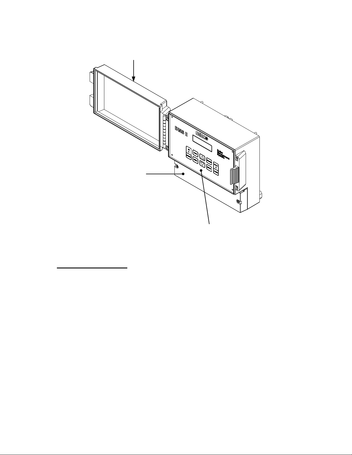
The BMS II is housed in a NEMA 13 e nclosur e. A hin ged cle ar-plas tic c over ove r the unit ’s panel cont rols
protects against inci den tal cont act of control settings a nd pro vi des a degree of protection a ga ins t a irbor n e
debris and the spraying or splashing of water. The physical dimensions, weight and electrical power
requirements for the BMS II are as follows:
Dimensions 9.50” W x 7.25” H x 4.00” D
Weight 3 lbs.
Power Requirements 85-to-265 VAC, Single-Phase, 50-60 Hz @ 1A
Each BMS II shipment includes a Header Sensor Kit, Part No. GM-122790 which is required for all modes
of operation. Other available options which can be ordered with your shipment include:
Outdoor Air Sensor Kit,
Part No. GM-122781
Required for Outdoor Reset Mode Operation
Return Sensor Kit,
Part No. 122790
(Same as Header Sensor Kit)
RS485-to-RS232 Converter, Part
No 124943
Used for external monitoring of boiler water return
temperature
For use with EMS or BAS equipment that do not include
a RS232 Port
1-1
Page 10
GENERAL INFORMATION
WIRING
COMPARTMENT
COVER
CONTROL
PANEL
CLEAR
PLASTIC
COVER
1.4 BMS II FEATURES
The following paragraphs briefly describe some of the unique features incorporated in the BMS II.
Simplified Installation and Set-Up
The BMS II system operates on single-phase input power ranging from 85 to 265 VAC, 50-60 Hz.
Connections to the boi ler plant are accom plished utilizing a 2-wire RS485 networ k connected in a d aisychain configuration. W hen an EMS or BAS is used with the B MS II, connec tions ar e made via the RS2 32
port terminals. In the event that the EMS or BAS is not equipped with a RS232 port, the BMS II can be
ordered with a RS485 to RS23 2 Converter which can be easily insta lled withi n the wiring c ompartm ent of
the BMS II. With the exception of AC power, interlock and setback inputs and relay outputs, BMS II
connections are accomplished using twisted-shielded pair cable.
User-Friendly Control System Interface
The unit incorporates a menu-driven architecture which is comprised of 9 primary menus. The user
interface to these m enus is ac c om plished v ia t he BM S I I contr ol pa nel and a V acuum Fluorescent Displ a y
(VFD). The displa y is c a pa ble of dis p laying two lines w ith 16 char ac ters per line. V ir tua ll y al l of t he c o ntrol
panel keys are identical to the C-More Contr ol System c urrently used on A ERCO Benchm ark Series and
KC1000 Boilers. This commonality will help simplify the time required for system setup of the BMS II.
Figure 1-1. Boiler Management System II (BMS)
1-2
Page 11

GENERAL INFORMATION
Retention of Menu Option Settings
By using non-volatile memory, the BMS II retains program and menu settings during shut-down or when
input AC power is interrupted. Settings can be retained for more than 2 years.
Application Flexibility
Four different configuration options can be selected to match the needs of any closed-loop system. These
configurations are: Outdoor Reset, Constant Setpoint, Remote Setpoint via a 4-20 Ma input and Remote
Setpoint via Modbus.
Sequential or Parallel Operation
Boilers can be programmed for either sequential or parallel operation using the BMS II keypad controls. When set
for sequential operation, the boilers are brought on-line one at a time as needed. When set for parallel operation, the
boilers are all brought on-line together at the same firing rate.
Accuracy
Using PID (Proportional Integral Derivative) and Ramp-Up/Ramp-Down Modulation Control Algorithms,
the BMS II provides dynamic responses to all changes in boiler plant operation. Header temperatures, as
well as percentages of boiler input are precisely controlled with virtually no over-shoot or short-c ycling of
boiler units. A header temperature accuracy of ±2°F is virtually assured during continuous plant operation.
Bumpless Transfer
When operated sequentially, The BMS II stages boilers on and off at selectable firing rate percentages.
The result is a seamless transition with undetectable room temperature changes. In addition, when in
sequential mode, the BMS II sequences boilers using a first-on, first-off basis, thereby equalizing the
accumulated run time of all boilers in the plant.
The BMS II also continuously monitors the number of Boilers that are available for operation. In the event
of a boiler malfunction, or required servicing, the BMS II automatically compensates for a lack of
response from any unit and brings on the next available boiler to satisfy the demand. This feature
operates in both sequential and parallel modes.
Fault Alarm Surveillance
If an EMS or BAS is not used with the BMS II to monitor faults, a Fault Alarm Relay can be activated
thereby notifying facility managers of faults associated with the BMS II.
BMS II Programming Via RS232 Port.
If desired, the BMS II can be programmed by connecting a Laptop Computer or other terminal emulation
device to the RS232 Port terminals on the BMS II. Detailed set-up instructions and available command
listings are provided in Ap p end ix G. Most settings are also programmable using Modbus.
1-3
Page 12

Page 13

INSTALLATION
CHAPTER 2 - INSTALLATION
2.1 INTRODUCTION
This Chapter provides the descriptions and procedures neces sary to mount the BMS II and connect all
boiler plant units and applic able sensors. Guideli nes are also provided for connec tion of an EMS or BAS
being used with the s ystem. Ref er to the wiring diagram provided in Appen dix E when mak ing all wiring
connections to the BMS II.
2.2 SITE SELECTION AND MOUNTING
Ensure that the site selected for installation of the BMS II provides the following:
• Access to single-phase AC power from 110 to 240 VAC, 60 Hz nominal
• Sufficient clearances to permit maintenance and setup/operational tasks on the BMS II.
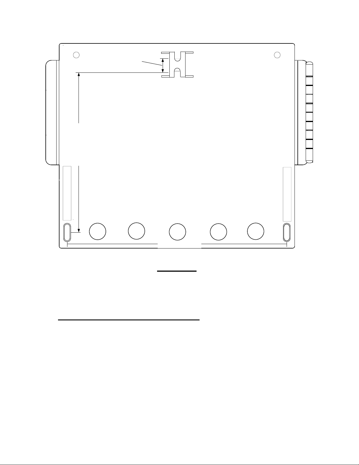
Mounting the BMS
AERCO recommends that the BMS II be wall-mounted using a sheet of plywood or other suitable
material. For easy viewing, the BMS II controls and display should be at eye level. Mounting is
accomplished using three screws (not provided). The s pacing for the three screws are indicate d on the
rear of the BMS II in millim eters. Figure 2-1 shows th e rear of the panel enc losure and also in dicates the
required spacing for the three mounting scr ews in inch es . Proceed as follows to mount the unit:
1. First install a screw o n the mounting sur face at the to p center locatio n shown in Figure 2-1. Lea ve a
space of approximately 1/8 inch between the mounting surface and the head of the screw.
2. Remove the wiring compartment cover f rom the front of the BMS II (see Figure 1-1) to provid e acc es s
to the slots for the two lower mounting screw locations.
3. Hang the BMS II on the installed top screw. Position the unit so it is level.
4. Mark the locations for the two lower screws.
5. Remove the BMS II and drill two pilot holes for the lower screws.
6. Replace the BMS II on the installed top-center screw.
7. Secure the BMS II to the wall by installing the two lower screws. DO NOT over-tighten the screws.
2-1
Page 14
INSTALLATION
198 mm (7.8")
145 mm (5.7")
15 mm
(0.6")
REAR VIEW
Figure 2-1. BMS II Mounting Provisions
2.3 GENERAL WIRING REQUIREMENTS
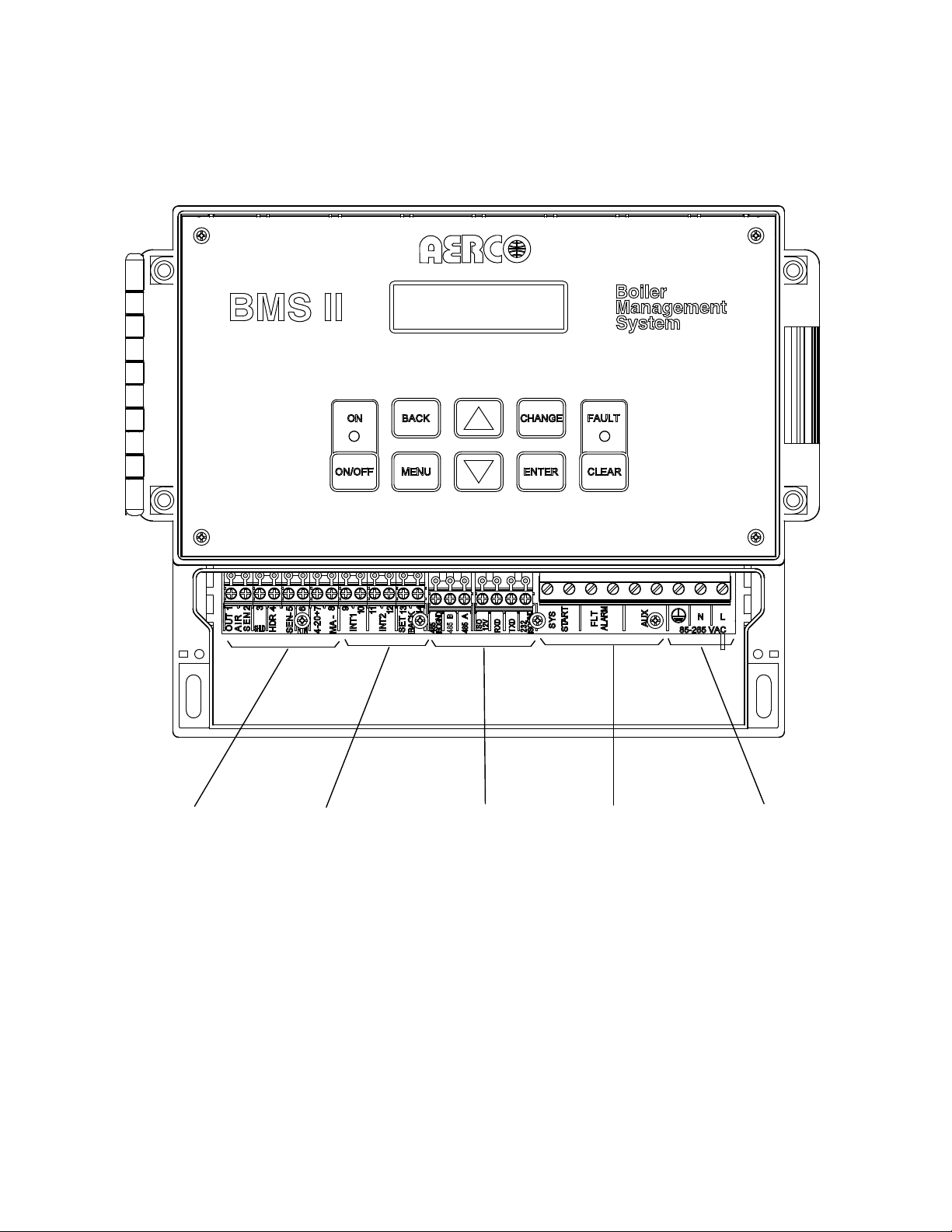
All wiring connections to t he BMS II are made at th e terminals located behind the wiring compartment
cover as shown in Fi gure 2-2. Run all wiring t hrough the knock-outs provided on the bottom sur face of
the unit. Shielded, twisted-pair cable should be used for sensor and communication wiring. This wiring
should be 18 to 24 AWG. Examples of s uitable sensor and comm unication wire are: Belden 9841, 87 61,
3105A or equivalent. AC power wiring should be 1 4 to 18 AWG. The BMS II wiring diagram is provided in
Appendix E. Once mount ing is com plete and the BMS is secured in p lace, loose n the two ca ptive scr ews
on the wiring compartment cover using a Phillips screwdriver. Feed all wiring through the knock-outs
provided on the bottom of the panel.
NOTE
Refer to the wiring diagram provided in Appendix E when making all
wiring connections to the BMS II.
2-2
Page 15

INSTALLATION
WARNING
THE BMS II CAN BE POWERED BY SINGLE-PHASE AC
VOLTAGES RANGING FROM 85 TO 265 VAC. THEREFORE,
EXERCISE EXTREME CARE WHEN CONNECTING POWER
WIRING TO THE UNIT. ENSURE THAT THE EXTERNAL
CIRCUIT BREAKER SUPPLYING LINE VOLTAGE TO THE BMS
II IS TURNED OFF TO AVOID SEVERE ELECTRICAL SHOCK.
2.4 POWER WIRING
Use 14 to 18 AWG wire for AC power connections and proceed as follows:
1. Feed the power wiring thr ough the right-m ost knock -out in the bottom of the panel enclosure (Figure
2-2).
2. Connect the Line (black ), Neutral (white) and Groun d (green) wire leads to the L, N an d
terminals. The term inal blocks can be detac hed fr om the BMS II headers if necess ary to sim plify field
wiring connections.
3. Following completion of power wiring, turn on the exter nal circuit breaker or switch and apply power
to the unit. The BMS II display will momentarily show:
AERCO BMSII
REV X.XX
(Where: X.XX represents the revision level of the installed BMS II software)
4. Next, since the Header Sensor is not yet installed, the display will then show:
HEADER TEMP
SENSOR ERROR
The red FAULT LED indicator will also light and a fault message will alternately be displayed as
follows:
HEADER SENSOR
ERROR
5. Press the ON-OFF k ey on the keypad. The green ON LED indicator w ill light and the BMS II d isplay
will continue to show the above message.
6. After verifying proper power connections, press the ON-OFF key. The ON LED will turn off.
(GND)
7. Turn off the external power switch and/or circuit breaker. The BMS II display will go blank.
8. DO NOT apply power to the BMS II until all of the required external connections described in
paragraphs 2.5 through 2.11 have been completed.
2-3
Page 16
INSTALLATION
SENSORS
& 4-20 mA
INTERLOCKS
& SETBACK
RS485
& RS232
AC POWER
RELAYS
2-4
Figure 2-2. BMS II With Wiring Compartment Cover Removed
Page 17

INSTALLATION
2.5 SENSOR INSTALLATION AND WIRING
There are two types of sensors that can be installed : a Header Sensor and an Outside Air Sensor. If
desired, an optional Return Sensor can also be installed. The Return Sensor is the same type and part
number as the Header S ensor, however it is only used for `external m onitoring purposes. The Header
Sensor is required for all
Outdoor Reset Mode.
All Sensor wiring should be run separately from power wiring to avoid inducing electrical noise on the
sensor wiring.
Header Sensor
A Header Sensor Kit, (part no. 12279 0) is provided with the BMS II. This Kit cont ains the Header Sensor
(64038), a Thermowell (122758) and some heat conductive grease which MUST be use d with the Sens or.
When installing the Sensor , use a 1/ 2 inch NPT tapped coupling or a 4 x 4 x 1/2 in ch T ee fitting. Shielded
pair, 18 AWG c able (Belden # 8760 or equiv.) is recommended for Header S ensor wiring. The Header
Sensor must be installed between 2 and 10 feet downstream of the LAST boiler in the boiler plant’s
supply water header. Install the Header Sensor as follows:
The Header Sensor is a thermistor type sensor. The Resistance vs.
Temperature Chart for this sensor is provided in Appendix D. The length
of the Header Sensor wire leads should not exceed 600 feet.
modes of operation. The Outdoor Air Sensor is required for operation in the
NOTE
1. Refer to Figure 2-3 f or the Header ‘Sens or ins ta llat ion details.
2. Install the Header Sensor and Thermowell i nto the 1/2 inch NPT tapped c oupling or a 4 x 4 x 1/2 inch
Tee fitting using heat-conductive grease provided. This will aid in its response.
3. For proper response , e ns ur e th at t he Hea der Sensor probe is inser ted at le ast 2 inc hes i nto the wat er
flow.
4. Using shielded pair c able (Belden #8760 or equiv.) connect t he Header Sensor leads to HDR SE N
terminals 4 and 5 on the BMS II. There is no polarity to observe when making these connections.
5. Terminate the cable shield at SHLD terminal 3 of the BMS II. DO NOT terminate the shield at the
Sensor end of the cable.
Return Sensor
As mentioned in paragraph 2.5, the Return Sensor is identical to the Header Sensor. Therefore, if a
Return Sensor is being ins talled, another Header Sensor K it (part no. 122790) is required. The Ret urn
Sensor should be i nstal led in the boiler water r eturn lin e within 3 feet of the first boil er in t he bo iler p lant ’s
return water line . The installation details sho wn in Figure 2-3 for the Header S ensor also apply to the
Return Sensor. If used, install the Return Sensor as follows:
1. Refer to Figure 2-3 an d ins tall the Ret ur n S ens or a nd Thermowell into the 1/2 inc h t ap ped c oupling or
or Tee fitting using heat conductive grease.
2. Using shielded pair ca ble (Belden #8760 or equiv.) connect the Retur n Sensor leads to term inals 6
and 5 on the BMS II. There is no polarity to observe when making these connections.
3. Terminate the cable shield at SHLD terminal 3 of the BMS II. DO NOT terminate the shield at the
Sensor end of the cable.
2-5
Page 18
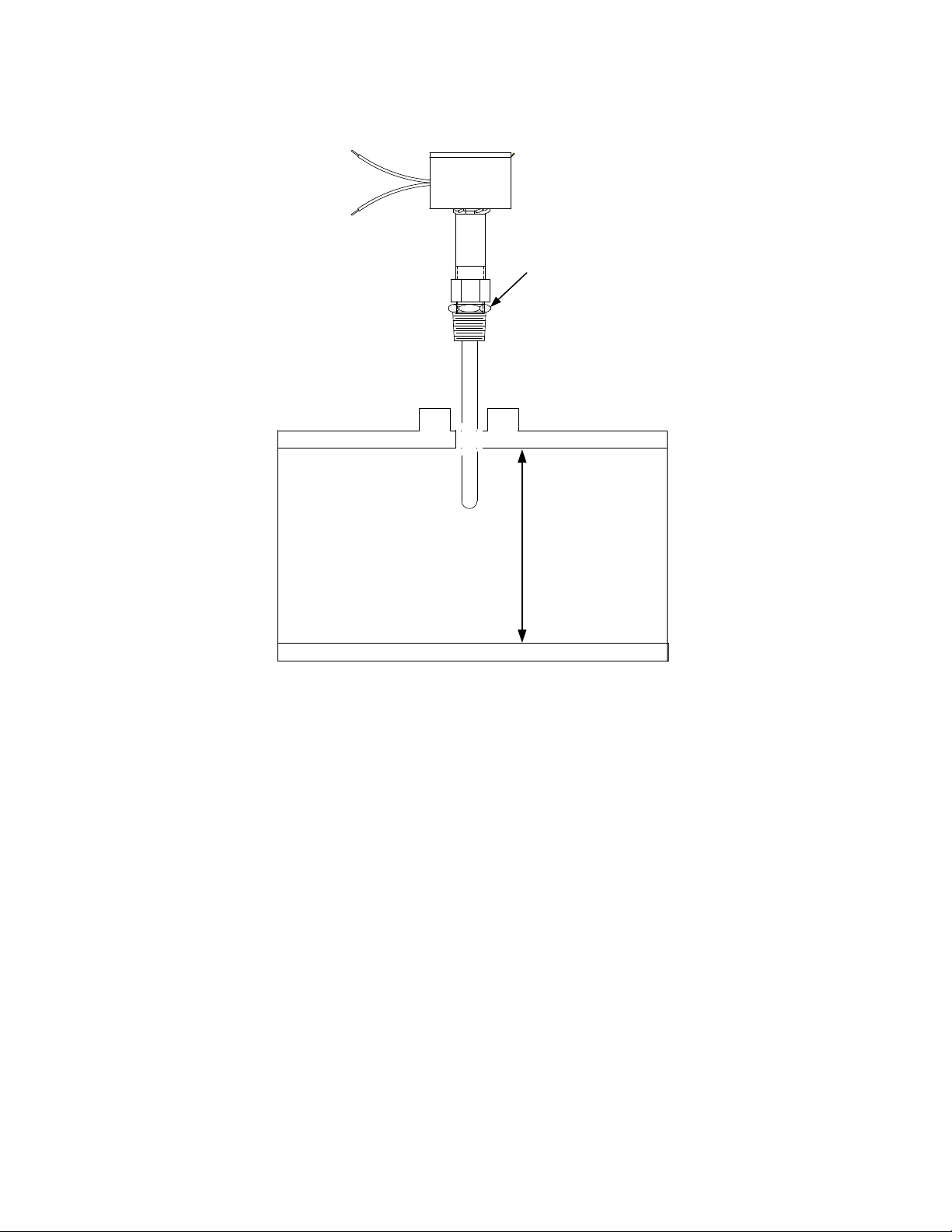
INSTALLATION
PROBE DEPTH MUST
EXTEND AT LEAST 2"
INTO PIPE
WELDED 1/2"
COUPLING OR
4"x4*x1/2"
T - FITTING
HEADER SENSOR
WITH THERMOWELL
INSTALLED
Figure 2-3. Header Sensor Installation Details
Outdoor Air Sensor
The Outdoor Air T emperature Sensor (part n o. GP-122662) is r equired when operating in the BMS II in
the Outdoor Reset Mode (paragraph 4.2). An Outdoor Air Sensor Kit (part no. GM-122781) is also
available. This kit contains the Sensor (GP-122662) and a Mounting Bracket for wall mounting. The
Outdoor Air Sensor should be mounted on the North side of the building, shielded from direct sunlight,
and awa y from air intakes or outlets f rom the building. Shielded pair 18 AWG cable (Belden # 8760 or
equiv.) is recomm ended for sensor wiring. The Outdoor Air Sensor can be m ounted up to 600 feet from
the BMS II.
1. Refer to Figure 2-4 for a typical Outdoor Air Sensor installation.
2. Attach the sensor to the mounting br acket and secure the bracket in a suitable loc ation on the North
side of the building.
3. Using shielded pair cable ( Belden #8760 or equiv.), connect t he two Sensor lea ds to terminals 1 and
2 on the BMS II. There is no polarity to observe when connecting the sensor.
NOTE
The Outdoor Air Sensor is a thermistor type sens or. The Resistance vs.
Temperature Chart for this t ype of s ensor is provi ded i n Appendix E. T he
length of the Header Sensor wire leads should not exceed 600 feet.
2-6
Page 19

INSTALLATION
INSTALL SENSOR ON NORTH
FACING WALL OUT OF DIRECT
SUNLIGHT AND AWAY FROM
ALL AIR INLETS/OUTLETS
4. Terminate the cable shield at SHLD terminal 3 of the BMS II. DO NOT terminate the shie ld at the
Sensor end of the cable.
Figure 2-4. Outdoor Air Sensor Installation
2-7
Page 20

INSTALLATION
MASTER
SLAVE
#1
SLAVE
#2
SLAVE
#3
SLAVE
#4
SLAVE
#5
2.6 RS485 (MODBUS) WIRING AT THE BMS II
The BMS II comm unicates with the AERCO Boilers over a RS485 network using Modbus pr otocol. All
Modbus networks are im plemented utilizing a Master/Slave scenario where onl y one device, the Master,
can initiate a communication sequence. AERCO Boilers equipped with C-More or E8/BCM (Modulex)
control systems can only function as Slaves on a Modbus network. However, the BMS II can function as a
Master controlling C-M ore or E8/BCM Boiler Slaves, or as a Slave contro lled by an Energ y Managem ent
System (EMS) developed by other manufacturers. Additional information on implementing Modbus
networks is provided in AERCO Modbus Communication Manual GF-114.
RS485 (Modbus) networks are wired in a “daisy chain” configuration similar to the example shown in
Figure 2-5. Shielded twisted-pair, 18 – 24 AWG cable (Belden #9841, #3105A, #8760 or equiv.) is
recommended for RS485 wiring connections.
Figure 2-5. Typical Daisy-Chain Modbus/RS485 Network
At the BMS II, RS485 (M odbus) wiri ng connections a re made at the wiring terminals labe led 485 B+ and
485 A-. The cable shield is terminated at the SHLD terminal (3) of the BMS II.
BMS II Bias Switches & Loop Termination Resistors
Each BMS II conta ins a built-in 120 ohm loop term ination resistor and two bias DIP switches which are
mounted on the lower portion of the motherboard (Figure 2-6). The 120 ohm termination resistor is always
active and is designed to matc h the electr ical im pedanc e at the B MS II end of the RS485 loop. T herefore,
only one additional termination resistor will be required at the boi ler end of the RS485 loop. The two bias
switches are used to activa te or deactiva te bias voltage on the RS485 networ k and should be positioned
as follows, depending on the type of AERCO boilers being used:
NOTE
Refer to paragraph 2.7 for detailed instructions and illustrations
describing how to implem ent loop termination, bias and wiring connections on the RS485 loop.
1. When wiring to Boiler C ontrol Modules (BCMs) controlling Mo dulex Boi lers, the BMS II bi as switches
must be activated b y placing them in the on (down) position. Loop term ination is accomplished by
activating the termination resistor in the last BCM on the RS485 loop.
2. When wiring to C-More co ntrol systems (Benchmark & KC1000 Boilers), the positions of the BMS II
bias switches will de pend on which one of the two available methods is used. Loop termination wil l
also depend on the method employed. See par agr aph 2.7 for details.
2-8
Page 21
INSTALLATION
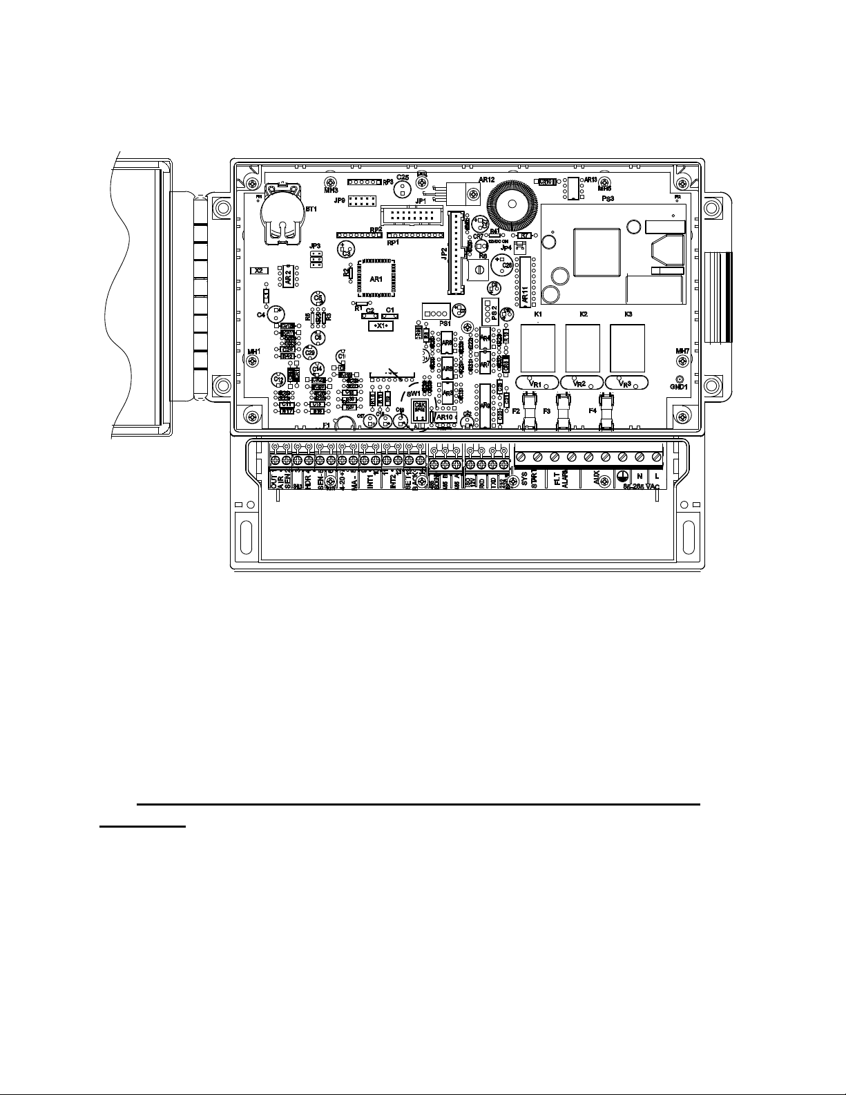
BIAS DIP
SWITCHES
NOTE:
THE BIAS DIP SWITCHES CAN BE ACCESSED
FROM THE WIRING COMPARTMENT WITHOUT
REMOVING THE FRONT PANEL FROM THE UNIT.
WIRING COMPARTMENT
Figure 2-6. Location of BMS II DIP Switches
2.7 RS485 (MODBUS) WIRING, BIAS & TERMINATION AT AERCO
BOILERS
The RS485 wiring connections at the AERCO Boilers will depend on the type of AERCO Boilers and
Control Systems bei ng used on the Mo dbus Network. Benchmark Series and KC1000 Boilers cur rently
utilize C-More Control S ystems. Modulex Series Boilers utilize Boiler Control Modu les (BCMs) with E8
Controllers.
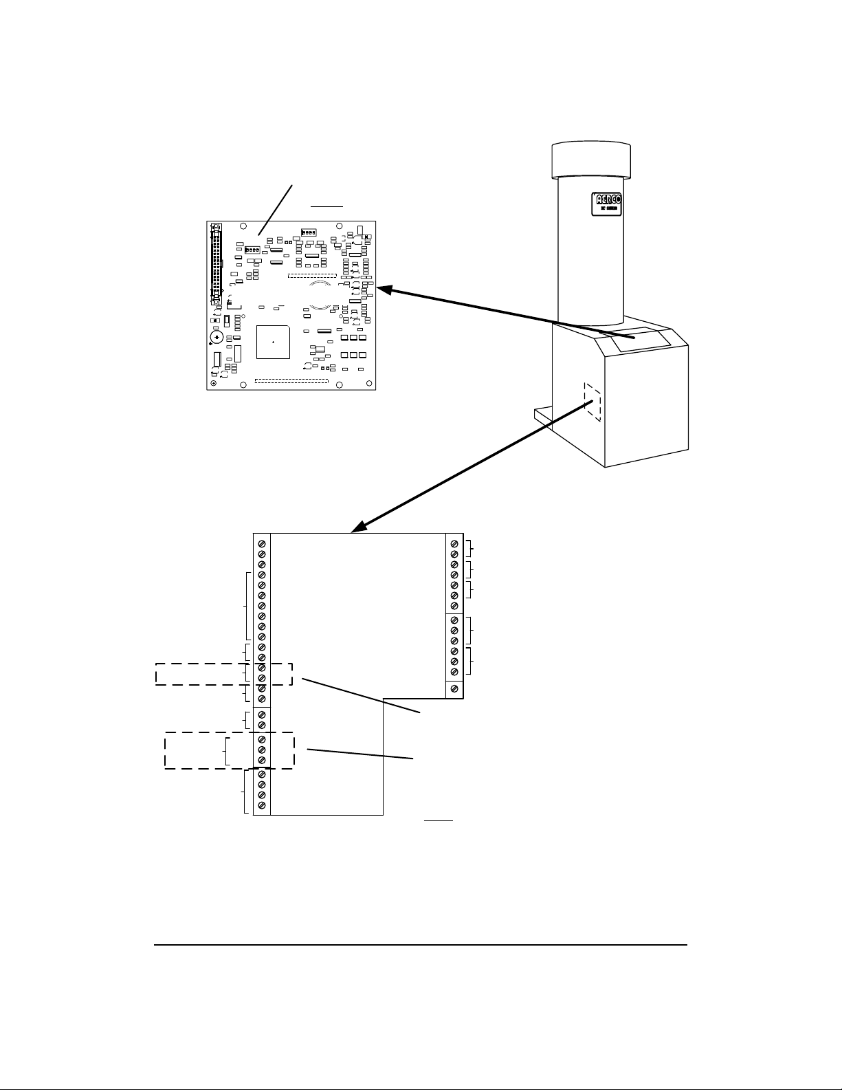
RS485 Wiring, Termination& Bias for Benchmark Series and KC1000 Boilers
RS485 wiring connec tions are m ade at the RS 485 CO MM term inals of each boiler’s I/O Box (Figures 2-7
or 2-8). However, activating bias and loop termination can be performed using one of two available
methods as described be lo w:
2-9
Page 22

INSTALLATION
Method 1
For Method 1, the bias switches in the BMS II are left in the deactivated (up) position. ). Bias and
termination are contr olled at the b oiler end of the RS485 loop by activatin g the bias and ter mination DIP
switches on the PMC board of the last
2-7 (Benchmark), or Figure 2-8 (KC1000) and proceed as follows:
1. Using a daisy-chain wiring configuration, connect the RS485 pos itive lead to the RS485 COMM +
terminal in the I/O Box for each boiler.
2. Connect the RS485 negative lead to the RS485 COMM - terminal in the I/O Box for each boiler.
3. DO NOT terminate the shields to the Ground (G) terminal at the boiler end of the RS485 loop.
Connect the s hields of the incom ing and outgoing lea ds togeth er. The RS485 loop shield should onl y
be terminated at terminal 3 of the BMS II.
4. At the last boiler in the daisy-chain, activate the BIAS1, BIAS2 and TERM switches on the PMC board
in the C-More Control Box. Refer to G F-114, paragraph 4.3.2 for detailed instru ctions on accessing
the PMC board.
5. DO NOT activate the bias switches on the B MS II. These switches m ust be in the up position when
using Method 1.
The advantage of us ing Method 2 is that the bias and termination of the
RS485 loop do not require any changes t o be made t o the DIP s witches
on the PMC board in the last C-More Control Box.
C-More Control Box on the daisy-chain. Refer to sheet 1 of Figure
NOTE
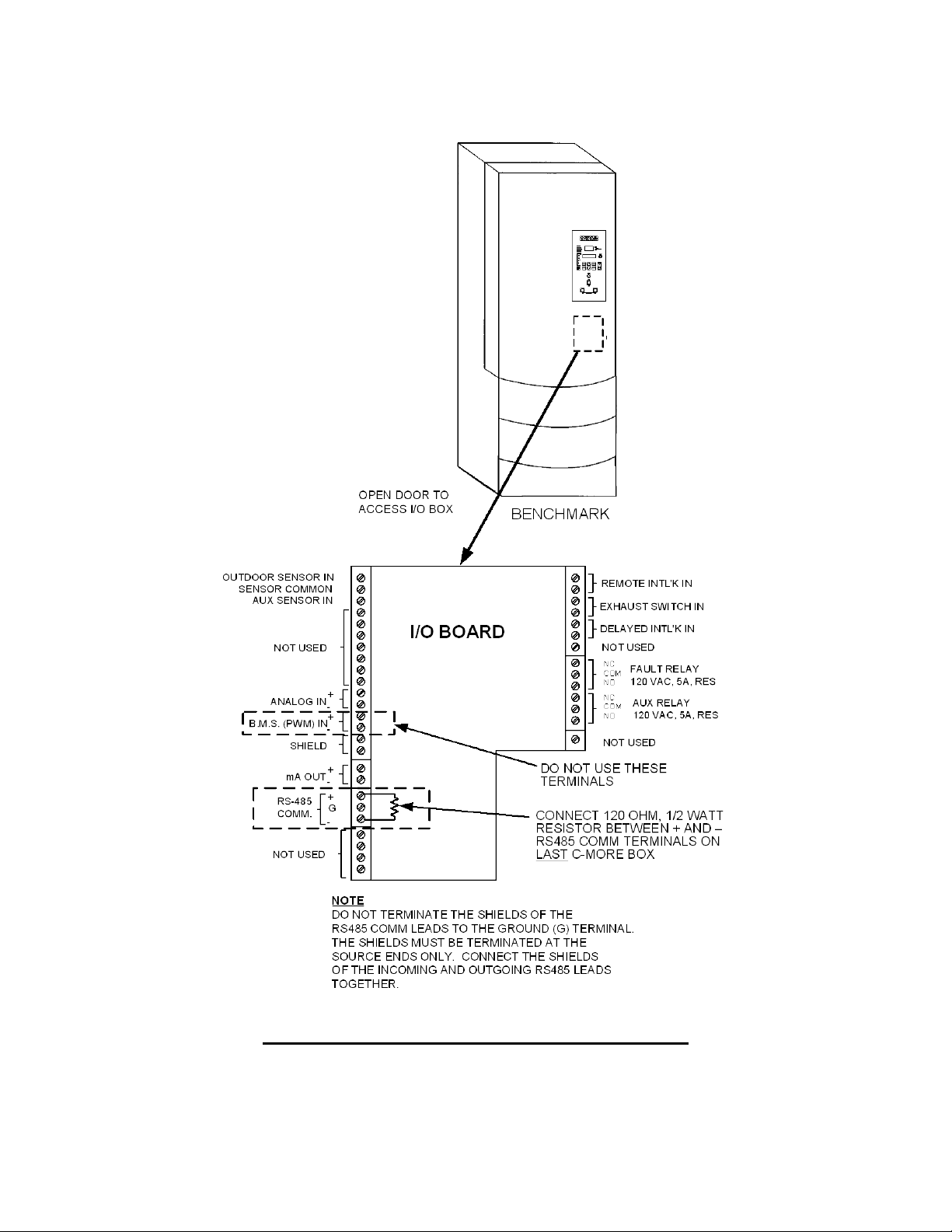
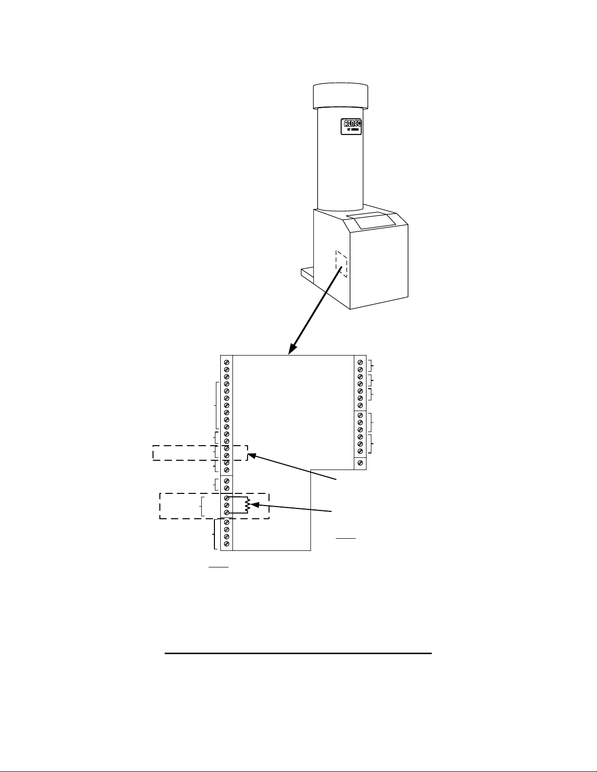
Method 2
For Method 2, bias is controll ed at the BMS II by setting the two bias switches (Figure 2-6) to the active
(down) position. Term ination at the boi ler end of RS48 5 loop is accomplished b y installin g a 120 ohm , 1/2
Watt termination resis t or in the I/O Box of the last
(Benchmark), or Figure 2-8 (KC1000) and proceed as follows:
1. Using a daisy-chain wiring configuration, connect the RS485 pos itive lead to the RS485 COMM +
terminal in the I/O Box for each boiler.
2. Connect the RS485 negative lead to the RS485 COMM - terminal in the I/O Box for each boiler.
3. DO NOT terminate the shields to the Ground (G) terminal at the boiler end of the RS485 loop.
Connect the shields of the incom ing and outgoing lea ds togeth er. The RS485 loop shield s hould onl y
be terminated at terminal 3 of the BMS II.
4. At the last boi ler in th e daisy-chain, install a 1 20 ohm , 1/2 W att term ination res isto r ac ross the RS485
COMM + and - terminals in the boiler’s I/O Box.
5. When using Method 2, activate the two bias switches in the BMS II (Figure 2-6) by placing them in the
down position.
boiler on the daisy-chain. Refer to s he et 2 of Figure 2-7
2-10
Page 23
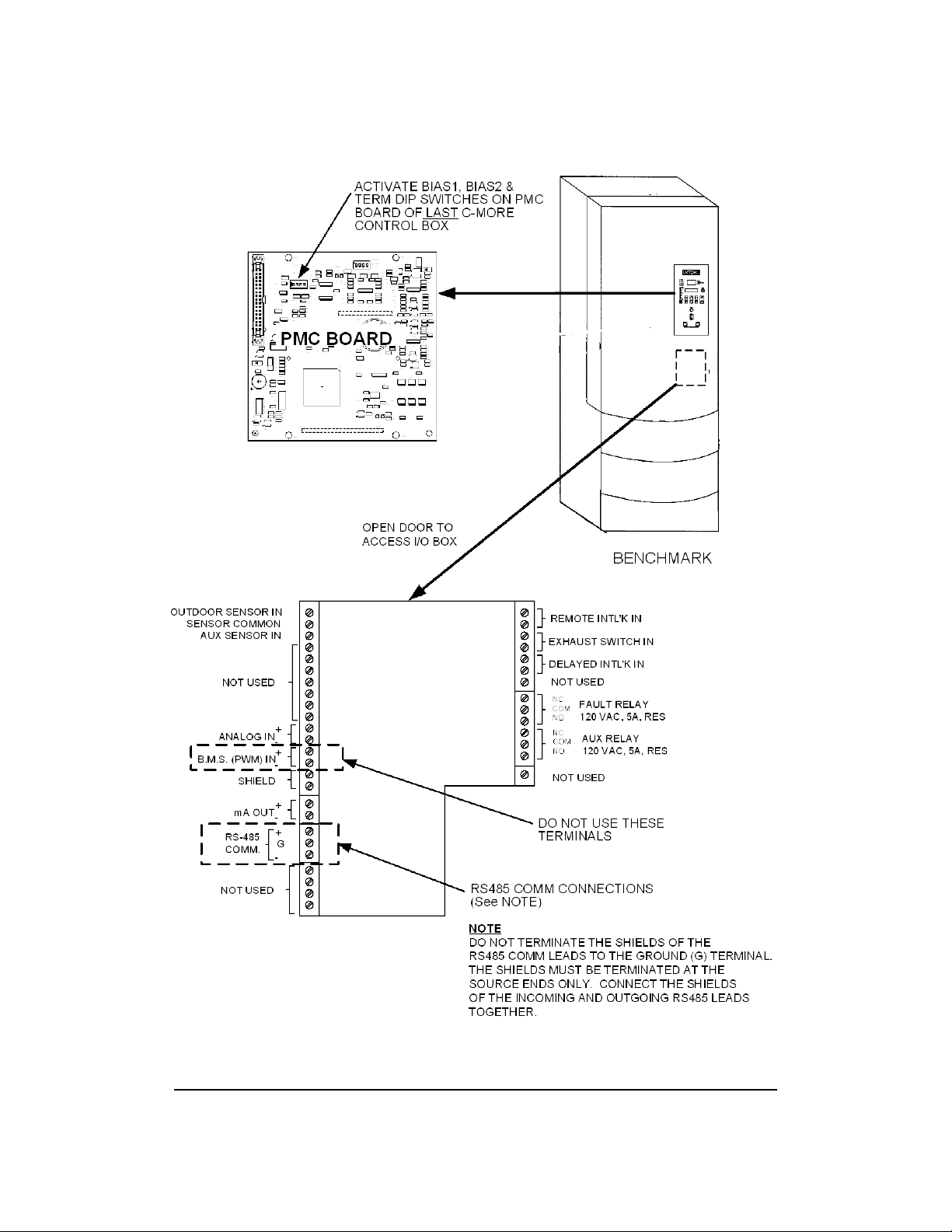
INSTALLATION
METHOD 1 – BIAS & TERMINATION ACTIVATED AT C-MORE PMC BOARD
Figure 2-7. RS485 (Modbus) Wiring For Benchmark Series Boilers (Sheet 1 of 2)
2-11
Page 24
INSTALLATION
METHOD 2 – TERMINATION ACTIVAT E D AT I/O BOX
Figure 2-7. RS485 (Modbus) Wiring For Benchmark Series Boilers (Sheet 2 of 2)
2-12
Page 25
mA OUT
RS-485
COMM.
+
-
+
-
ANALOG IN
SENSOR COMMON
OUTDOOR SENSOR IN
REMOTE INTL'K IN
B.M.S. (PWM) IN
SHIELD
+
-
+
-
AUX SENSOR IN
NOT USED
EXHAUST SWITCH IN
DELAYED INTL'K IN
FAULT RELAY
120 VAC, 5A, RES
AUX RELAY
120 VAC, 5A, RES
G
NOT USED
NOT USED
NC
COM
NO
NC
COM
NO
NOT USED
NOTE
DO NOT TERMINATE THE SHIELDS OF THE
RS485 COMM LEADS TO THE GROUND (G) TERMINAL.
THE SHIELDS MUST BE TERMINATED AT THE
SOURCE ENDS ONLY. CONNECT THE SHIELDS
OF THE INCOMING AND OUTGOING RS485 LEADS
TOGETHER.
C32
Q1
C41
C29
C20
C31
C35
C47
C44
R29
R30
HB
C53
R74
C4
C3
U1
CBS3
R69
C50
R67
R68
Y1
C52
C57
J2
CR1
C1
C5
U17
R76
C51
R71
R73
R72
C2
JP2
R70
U21
C56
C6
C64
R75
J4
U13
U20
C59
C49
C48
C61
CBS4
U14
R78
R79
DS5
DS4
RS232
TX
RX
C60
C62
C46
U19
U15
U18
C58
C55
C54
DS3
R77
Y2
U16
C63
B1
R16
U11
R66
U10
R15
C45
R14
C19
C16
R32
R17
C18
R18
C34
U4
R33
C27
R31
C26
U6
R47
C39
R55
U2
R1
C7
U8
R53
C36
R81
R45
R44
C37
R48
S2
R46
C38
R49
J1
BIAS1
TERM
BIAS2
R50
C40
CBS1
RS485
C11
J3
R51
R9
BH1
U3
R10
C12
C13
DS1
RS485
TX
RX
R52
U7
DS2
R54
R5
C10
R7
R8
R6
S1
R11
R65
C9
R34
R12
R13
C14
C15
R36
C28
C25
R35
C23
R37
R38
C30
U5
C43
C65
R2
R3
R58
C8
R62
R4
R80
OFF = VOLT
CURR/VOLT
ON = CURR
Q2
R57
C66
R64
R56
CBS2
R25
U12
R20
U9
R19
C17
R27
R23
R21
R22
C21
R28
R26
C24
R60
R41
R40
R24
R39
C22
R42
R43
C33
R61
R63
C42
R59
CR2
PMC BOARD
ACTIVATE BIAS1, BIAS2 & TERM
DIP SWITCHES ON PMC BOARD
OF LAST
C-MORE CONTROL BOX
DO NOT USE THESE
TERMINALS
KC1000
REMOVE SHEET METAL
COVER TO ACCESS I/O BOX
RS485 COMM CONNECTIONS
(See NOTE)
I/O BOARD
INSTALLATION
METHOD 1 – BI AS & T E RMI NATI ON AC T IVATED AT C -M ORE PMC BOARD
Figure 2-8. RS485 (Modbus) Wiring For KC1000 Boilers (Sheet 1 of 2)
2-13
Page 26
INSTALLATION
mA OUT
RS-485
COMM.
+
-
+
-
ANALOG IN
SENSOR COMMON
OUTDOOR SENSOR IN
REMOTE INTL'K IN
B.M.S. (PWM) IN
SHIELD
+
-
+
-
AUX SENSOR IN
NOT USED
EXHAUST SWITCH IN
DELAYED INTL'K IN
FAULT RELAY
120 VAC, 5A, RES
AUX RELAY
120 VAC, 5A, RES
G
NOT USED
NOT USED
NC
COM
NO
NC
COM
NO
NOT USED
NOTE
DO NOT TERMINATE THE SHIELDS OF THE
RS485 COMM LEADS TO THE GROUND (G) TERMINAL.
THE SHIELDS MUST BE TERMINATED AT THE
SOURCE ENDS ONLY. CONNECT THE SHIELDS
OF THE INCOMING AND OUTGOING RS485 LEADS
TOGETHER.
DO NOT USE THESE
TERMINALS
CONNECT 120 OHM, 1/2 WATT
RESISTOR BETWEEN + AND –
RS485 COMM TERMINALS ON
LAST
C-MORE CONTROL BOX
KC1000
REMOVE SHEET METAL
COVER TO ACCESS I/O BOX
I/O BOARD
METHOD 2 – TERMINATION ACTIVATED AT I/O BOX
Figure 2-8. RS485 (Modbus) Wiring For KC1000 Boilers (Sheet 2 of 2)
2-14
Page 27
INSTALLATION
Y2
Y3
Y4
Y1
SW1
A1
I
0
BCM FRONT VIEW
7 6 5 4 3 2 1
Y2
JP2
JP1
T
C
V
JUMPER
SHOWN IN
“TERMINATED”
(UP) POSITION
MODBUS B (+)
MODBUS A (-)
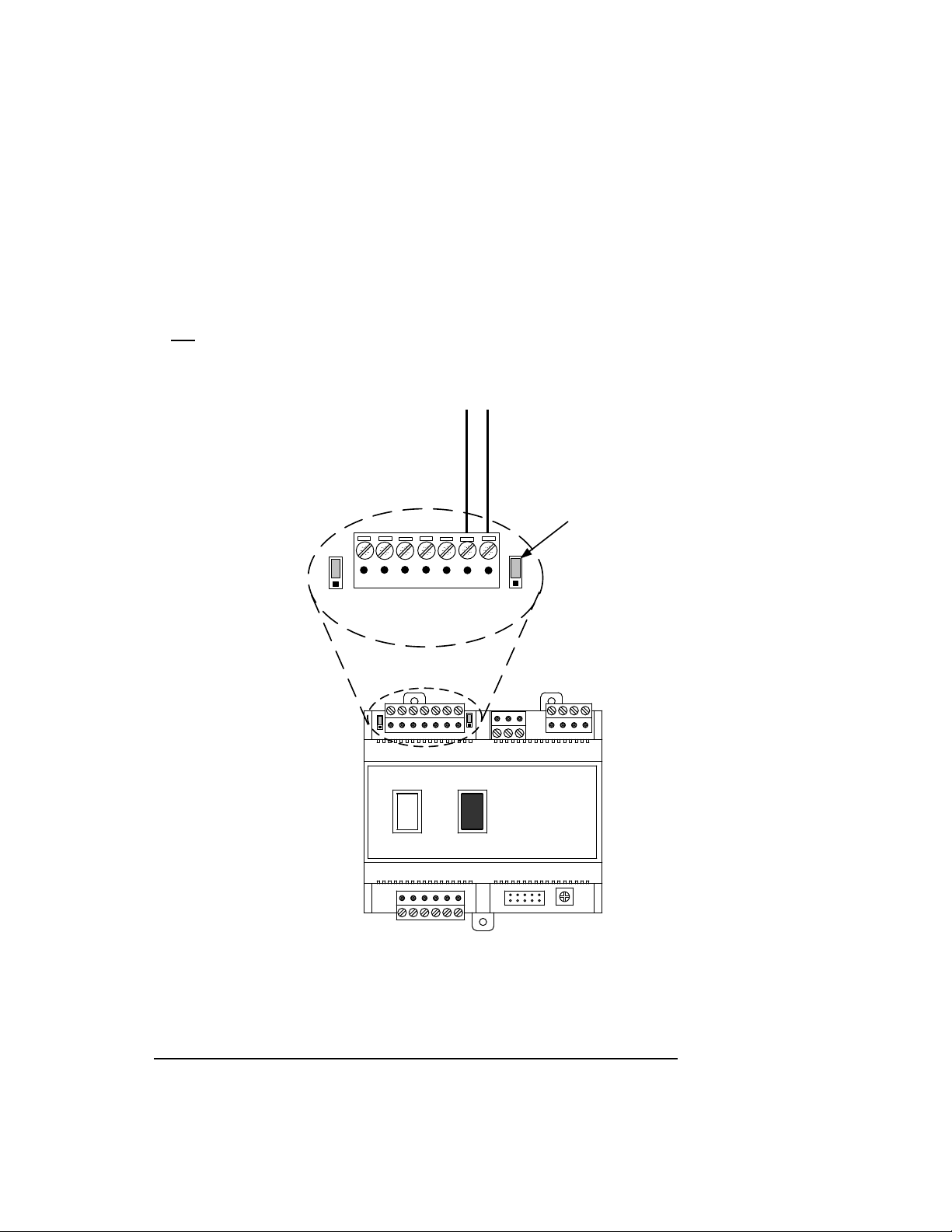
RS485 Wiring for Modulex Series Boilers
RS485 wiring connec ti ons ar e made at the MODBUS t erminals of each Boiler ’s BCM Module as shown in
Figure 2-9. Connect the wiring as follows:
1. Connect the positive lead to terminal 1 (MO DBU S B + ) of connec tor Y2.
2. Connect the negative lead to terminal 2 (MODBUS A -) of connector Y2.
3. DO NOT terminate the shields at the Boiler end of the RS485 loop. Connect the shields of the
incoming and outgoing leads together. T he RS485 loop shield should onl y be terminated at th e BMS
II.
4. The last BCM in the daisy-chain must have the termination jumper engaged as shown in Figure 2-9.
5. The two BMS II bias switches (Figure 2-6) must be activated by placing them in the down position.
Figure 2-9. RS485 (Modbus) Wiring For Modulex Series Boilers
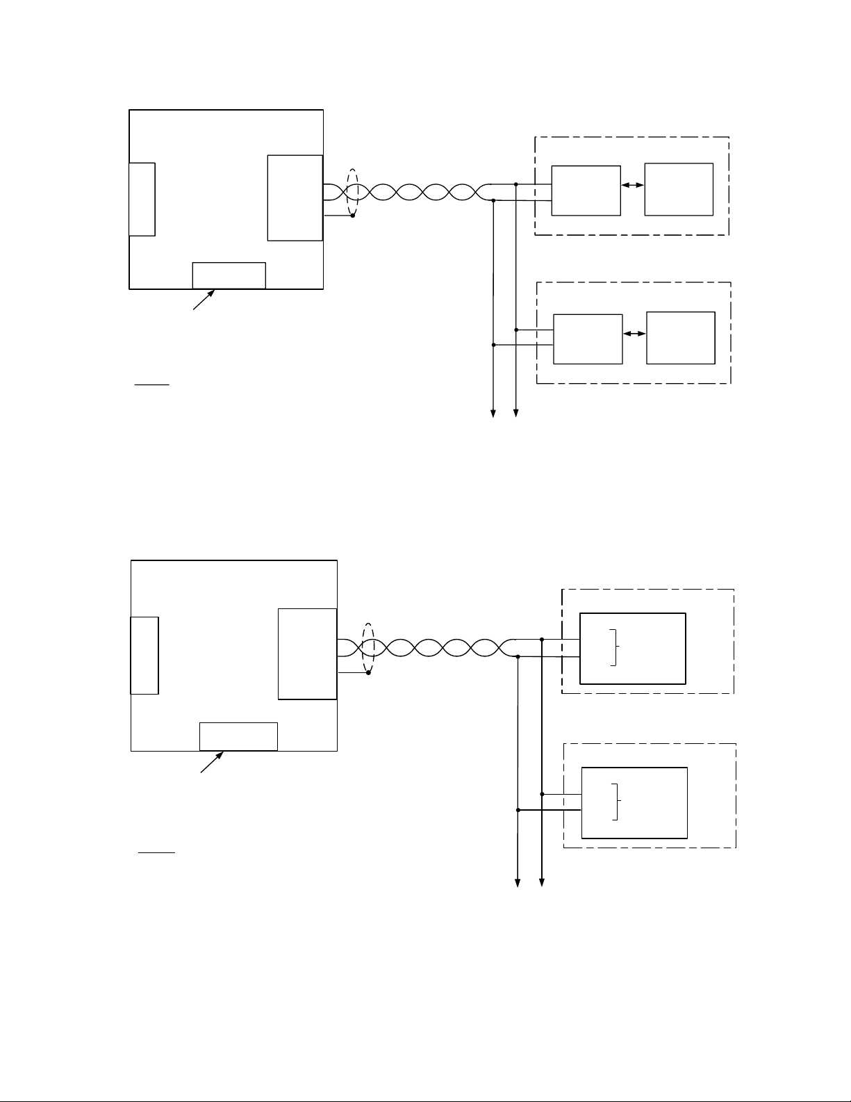
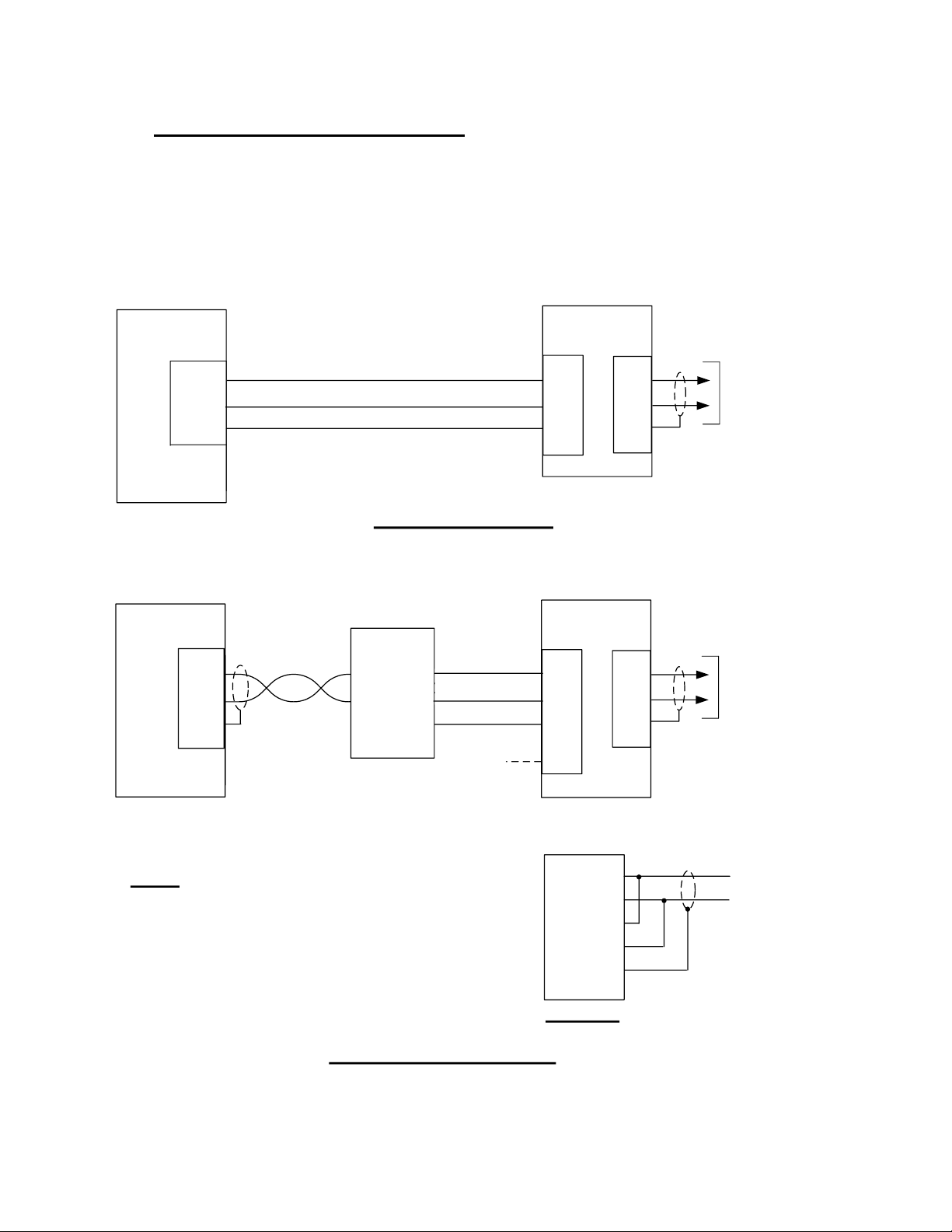
2.8 SAMPLE RS485 (MODBUS) NE TWORK DIAGRAMS
Figure 2-10 shows a sam ple RS485 ( Modbus) Net work diagram with the BMS I I connecte d to KC1000 or
Benchmark Series Boilers equipped with C-More Control S ystems. Figure 2-11 sho ws a similar sample
diagram with the BMS II connected to Modulex Series Boilers equipped with BCMs and E8 Controllers.
2-15
Page 28
INSTALLATION
BMS II
RS232 PORT
485 B (+)
485 A (-)
SHLD
(TERM. 3)
-
+
RS485
COMM
P/O I/O BOX
C-MORE
SLAVE
NETWORK BOILER 1
-
+
RS485
COMM
P/O I/O BOX
C-MORE
SLAVE
NETWORK BOILER 2
TO OTHER
NETWORK
BOILERS
(3 – 32)
RS485 PORT
NOTE
THE LAST C-MORE SLAVE ON THE RS485 LOOP
MUST HAVE ITS TERMINATION RESISTOR (TERM)
AND BIAS (BIAS1, BIAS2) DIP SWITCHES TURNED
ON. REFER TO GF-114 MODBUS COMMUNICATION
MANUAL FOR DETAILS.
THE BIAS SWITCHES IN THE BMS II SHOULD BOTH
BE “OFF”
SET BOTH
SWITCHES
TO “OFF”
BIAS
SWITCHES
BMS II
RS232 PORT
485 B (+)
485 A (-)
SHLD
(TERM. 3)
TO OTHER
NETWORK
BOILERS
(3 – 9)
RS485 PORT
NOTE
THE LAST BCM SLAVE ON THE RS485 LOOP MUST
HAVE ITS TERMINATION RESISTOR (T) ACTIVATED.
REFER TO GF-115-C FOR MORE INFORMATION.
THE BIAS SWITCHES IN THE BMS II SHOULD BOTH
BE TURNED “ON”.
SET BOTH
SWITCHES
TO “ON”
BIAS
SWITCHES
B (+)
P/O BCM (Y2)
NETWORK BOILER 1
1
2
A (-)
MODBUS
B (+)
P/O BCM (Y2)
NETWORK BOILER 2
1
2
A (-)
MODBUS
Figure 2-10. Sample RS485 (Modbus) Network For Benchmark or KC1000 Boilers
Figure 2-11. Sample RS485 (Modbus) Network For Modulex Series Boilers
2-16
Page 29
INSTALLATION
RS232
(50 FT. MAX.)
EMS
T+/R+
SHLD
RS485 PORT
T-/R-
SEE NOTE 1
TO BOILERS
CONTROLLED
VIA RS485
NETWORK
(4000 FT. MAX.)
485
PORT
RXD
TXD
+(B)
-(A)
SHLD
BMS II
232
PORT
ISO
GND
+
-
TXD
RXD
GND
RS485-TO-RS232
CONVERTER
RS485
(4000 FT. MAX.)
ISO
12V
SEE
NOTE 2
T+
R-
R+
T-
SHIELD
4-WIRE RS485 PORT
DETAIL “A”
NOTES:
1. IF THE EMS CONTAINS A 4-WIRE RS485 PORT,
SEE DETAIL “A”.
2. THE BMS II PROVIDES A 12V OUTPUT IF
NEEDED TO POWER THE RS485-TO-RS232
CONVERTER.
RXD
TXD
+(B)
-(A)
SHLD
TO BOILERS
CONTROLLED
VIA RS485
NETWORK
(4000 FT. MAX.)
BMS II
485
PORT
RS232 (50 FT. MAX.)
EMS
TXD
GND
RS232 PORT
RXD
232
PORT
ISO
GND
EMS WITH RS232 PORT
EMS WITH ONLY RS485 PORT
2.9 RS232 WIRING AT THE BMS II
The BMS II comm unicates with an external Energy Mana gement System (EMS) or Building Automation
System (BAS) ut ilizing the wiring terminals labe led RXD (Receive D ata), TXD (T ransmit Data) and 232
ISO GND (Is olated Ground). If the EMS does not contain an RS232 port, a RS485-to-RS232 Converter
(AERCO Part No. 124943) is r equired to communicate with t he BMS II. If a Converter is required, it can
be installed inside the wiring compartment of the BMS II, or installed exter nally. The BMS II provides an
isolated 12 VDC output terminal (ISO 12V) which can be used to power AERCO’s RS485-to-RS232
Converter if needed. Refer to Figure 2-12 for sample network layouts.
Figure 2-12. Sample Network Connections To EMS
2-17
Page 30

INSTALLATION
2.10 INTERLOCK WIRING
The BMS II is equipped with two interlocks designated Interlock 1 (INT 1) and Interlock 2 (INT 2). Since
both interlocks m us t be c lo sed f or the BM S t o o per ate the bo iler pl ant, the associated wiring terminals are
jumpered, prior to shipm ent. If desired, proving device switches can be c onnected to either
place of the jumper. If used, interlock wiring connections are made as described in the following
paragraphs.
CAUTION
DO NOT remove the factory-installed jumpers for INT1 or INT2
unless the respective Interlock is being connected to an external
proving device. The boiler plant WILL NOT operate if one or both
Interlocks remain open.
NOTE
If necessary, Interlock 1, Interlock 2 or both can be programmed
to operate the boilers only when the outdoor air temperature f alls
below the system start temperature. The selection is made with
“SYS START INTLK” in the Relay Menu. The default is set to
Interlock 1. See paragraph 3.11 for detail s.
interl ock in
Interlock 1 (INT 1) Wiring
Interlock 1 is often us ed with auxiliary equipm ent, such as air dam pers or flow switches. It can also be
used as a general purpose interlockIf used, connect the end proving switch to INT 1 terminals 9 and 10 as
shown in the wiring diagram in Appendix E.
Interlock 2 (INT 2) Wiring
Similar to Interlock 1, Interlock 2 is a general purpose interlock which can be used with a variety of
devices or equipment or conditions that must be “proved” prior to enabling the boiler plant. If used,
connect the end prov ing switch to INT 2 terminals 11 and 12 as shown in the wiring d iagram in Appendix
E.
2.11 SET BACK WIRING
The SET BACK terminals, shown in the wiring di agram in Appe ndix E, are used only when im plem enting
a manually-controlled header temperature offset. If used, connect a dry contact switch across SET
BACK terminals 13 and 14. See the sub-section entitled Ma nual Offset included in par agraph 3.8 (Field
Adjust Menu),
2.12 RELAY WIRING
The BMS contains a System Start (SYS START) Relay, a Fault Alarm (FLT ALARM) Relay and an
Auxiliary (AUX) R elay which can be conn ected to external monitoring or c o ntrol d ev ic es. The contacts for
each of these relays are rat ed at 120 V AC, 5A an d are fus ed internall y at 5A with replace able f uses . The
contact terminals for these relays are shown in the wiring diagram in Appendix E.
2-18
Page 31

INSTALLATION
NOTE
The state of the SYS START, FLT ALARM and AUX Relays are
controlled by options contained in the Relay Menu described in
Chapter 3, paragraph 3.11.
System Start Relay
The state of the System Start (SYS ST ART) relay contacts are controlled b y the value set for the S YS
START TEMP and SYS START OPTION in the Relay Menu. The contacts ar e closed either when the
outdoor air tem perature is less than the System Start Tem perature ( SYS STAR T TEMP) or when there is
a load, or both. T he default value for this temperature setting is 70°F. See paragraph 4.5 f or additional
information.
Fault Alarm Relay
The state of the Fault Alarm (FLT ALARM) relay contacts are controlled by the option select ed for the
FAULT ALRM RELAY, FAULT ALARM BLR and FAULT ALRM CLEAR in the Relay Menu. Contact
closure can be set to: AL L FAU LTS, NO INTERLOCK, INTERLOCK 2 or INTERLOCK 1. The default f or
this option is ALL FAULTS.
Auxiliary Relay
The state of the Auxiliary (AUX) relay contacts are controlled by the AUX RELAY CLOSE and AUX
RELAY OPEN options selected in the Relay Menu. Contact closure can be set to occ ur either when all
available boilers are at the 100% Fire Rate or for either when all boilers are at 100% Fire Rate or no
boilers are available (all boilers faulted or turned off).
2.13 4 – 20 MA WIRING
The BMS II can accept a remote 4 – 20 m A current signal representing a setpoint. T his input is fused
internally at 0.63A. Connect the signal leads to the 4-20 + and 4–20 – terminals. Refer to Chapter 4,
paragraph 4.3 for Remote Setpoint programming using a 4 -20 mA input.
2-19
Page 32

Page 33

OPERATION
CHAPTER 3 - OPERATION
3.1 INTRODUCTION
The information in this Chapter provides a guide to t he operation of the BMS II using the controls and
display mounted on th e front panel of the unit. This Chapter describes the basic procedure to navigate
through the extensive ar ray of menus and options incor porated in the B MS II design. Des criptions for a ll
menus and options are also provided.
3.2 FRONT PANEL OPERATING CONTROLS AND DISPLAYS
The front panel of the BMS II cont ains an vacuum fluorescent displa y (VFD) and an 8-key touch-pad. T he
display and controls are illustrated and described in Figure 3-1 and Table 3-1 respectively.
Figure 3-1. BMS II Front Panel Controls and Displays
3-1
Page 34

OPERATION
FUNCTION
6
ON Indicator
Green ON LED lights when the BMS II is enabled.
Table 3-1. BMS II Front Panel Controls and Displays
ITEM
NO.
CONTROL, INDICATOR
OR DISPLAY
1 VFD Display The Vacuum Fluorescent Display (VFD) display consists of 2
lines each capable of displaying up to 16 alphanumeric
characters. The information displayed includes:
• Startup Messages
• Alarm Messages
• Operating Status Messages
• Menu Selections
FAULT Indicator Red FAULT LED indicator lights when a BMS II alarm
2
condition occurs. An alarm message will also appear in the
VFD display.
CLEAR Key
3
MENU Keypad
4
Turns off the FAULT indicator and relay if FAULT ALRM
CLEAR is set to Manual and the fault is still active or no
longer active. If FAULT ALRM CLEAR is set to Automatic
and the fault is still active, this will also turn off the fault relay
and indicator. In both cases the alarm message will remain
until the alarm is no longer valid.
Consists of 6 keys which provide the following functions for
the BMS II menus:
MENU
BACK
▲ (Up) Arrow When in one of the main menu categories, pressing this key
▼ (Down) Arrow When in one of the main menu categories, pressing this key
CHANGE
ENTER
Steps through the main menu categories shown in Figure 2-1.
The Menu categories wrap around in the order shown.
Allows you to go back to the previous menu level without
changing any information. Cont inuous ly pressing this key will
bring you back to the default status display in the Operating
Menu. Also, this key allows you to go back to the top of a
main menu category.
will move you forward through the displayed menu category.
If the CHANGE key was pressed and the menu item is
flashing, press the ▲ arrow key increment the setting.
will select the displayed menu category. If the CHANGE key
was pressed and the menu item is flashing, pressing the ▼
(Down) arrow key will decrement the selected setting.
Permits a setting to be changed (edited). A valid password
must be entered before changing most menu items. When
the CHANGE key is pressed, the displayed menu item will
alternate in color with the background (reverse video).
Pressing the ▲ or ▼ arrow key when this occurs will
increment or decrement the displayed setting.
Saves the modified menu information in memory. The
display will return to the normal state.
ON/OFF Key
5
3-2
Enables and disables BMS II operation.
Page 35

OPERATION
3.3 BMS II MENU STRUCTURE
The BMS II incorpora tes an extens ive m enu str ucture which perm its the op erator to set u p, and c onf igure
the unit. The menu s tructure c onsists of nine maj or menu cat egories as s hown in Figure 3-2. Each of the
menus shown, contain opt ions which permit oper ating parameters to be view ed or changed. The menus
are protected by two different password levels to prevent unauthorized use. These passwords provide
access as follows:
• Password Level 1 (159) allows viewing of all menu categories. In addition, this Password Level allows
all Menu options to be changed, except for Calibration Menu options.
• Password Level 2 (6817) allows viewing and changing of the options contained in the Calibration
Menu. In addition, it allows all Level 1 menu categories to be viewed or changed. The Calibration
Menu should only be used by factory-trained personnel.
Prior to entering the corr ect password, the options contained in al l of the Menu categor ies (except the
Calibration Menu) can be viewed. However, except for Internal Setpoint Temperature (Field Adjust Menu),
none of the viewable menu options can be changed.
Once the valid Leve l 1 (159) or Level 2 (6817) password is entered, the opt ions listed in the available
menus can be viewed and changed, if desired.
Menu Processing Procedure
Accessing each m enu and option is accom plished using th e Menu Ke ys shown in Figure 3-1. Therefore,
it is imperative that you be thorou ghly familiar with th e following basic steps before attem pting to perform
specific menu processing procedures.
1. The BMS Il will normall y be in the Operating Menu and the VFD will d isplay the current unit status.
Pressing the ▲ or ▼ arrow key will display the other available data in the Operating Menu.
2. Press the MENU key. The display will show the Setu p Menu which is the nex t menu categor y shown
in Figure 3-2. This m enu conta ins the Pas sword optio n which m ust be entered if other menu opt ions
will be changed.
3. Continue pressing the MENU key until the desired menu is displayed.
4. With the desired m enu d isp layed, press the ▲ arr o w k e y. The f ir st option in the selected menu will be
displayed.
5. Continue pressing the ▲or ▼ arrow key until the desi red menu option is displayed. Press ing the ▲
arrow key will displa y the available m enu options in the Top-Down sequence. Press ing the ▼ arrow
key will display the options in the Bottom-Up sequence. The menu options will stop when the last
option is reached, go ing forward, or the first option is reached, going back wards. They do not wraparound after the first or last available option.
6. To change the value or setting of a displayed menu option, press the CHANGE key. The displayed
option will appear in revers e video. Press the ▲ or ▼ arrow k ey to scroll through the availab le menu
option choices for the option to be changed. The menu option choices do not wrap around.
7. To select and store a changed menu option, press the ENTER key.
3-3
Page 36

OPERATION
OPERATING
SETUP
RS232
RS485
FIELD ADJUST
CONFIGURATION
TUNING
RELAY
CALIBRATION
LEVEL 1 PWD
LEVEL 2 PWD
Figure 3-2. BMS II Menu Structure
3-4
Page 37

OPERATION
NOTE
Paragraphs 3.4 through 3.12 provide detailed descriptions of the
options contained in each of the menus shown in Figur e 3-2. The
menu options appear in the first line of the VFD display and the
corresponding value or setting for the displayed option will appear
in the second line of the display.
Refer to Appendix A for tabular summaries of all menu options
showing the allowable entry ranges and default values,
3.4 OPERATING MENU
The Operating Menu disp lays a number of key operating p arameters for the BMS II: These parameters
include:
HEADER TEMP, HEADER SETPO INT, OUTSIDE AIR TEMP, PE RCENT OF LOAD, I/O STATUS and
RETURN TEMP.
All of the item s in this menu ar e “Read-Only” and do not allow personnel to c hange or adjust an y of the
displayed param eters. Since this menu is “Read O nly”, it can be viewed at any tim e without entering a
password. The Operating Menu options are described in the paragraphs which follow.
HEADER TEMP and PERCENT OF LOAD
The H EADER TEMP m enu option displays the actual water tem perature (°F) m easured by the Header
Sensor c onnected to HDR SEN terminals 4 and 5 of the BM S II. If the Header Sensor is not installed,
HDR SENS ERROR will ap pear in the first line of the display. T he red FAULT indicator will a lso lig ht. The
Header Sensor MUST be installed for the BMS II to operate properly.
The PERCENT OF LOAD option shows the percent level going from the BMS II to each boiler in the
boiler plant. It also shows the number of boiler units that are operating.
HEADER SETPOINT
This menu option is the se tpoint temperature to wh ich the control is set when operat ing in the Constant
Setpoint, Remote Setpoi nt or Outdoor Reset Mode. W hen in the Constant Setpoint Mode, this value is
equal to the Internal Setpoint s etting in the Co nfigur ati on Menu. W hen in the Rem ote Setpoin t Mode, this
value is the setpoint equiv alent to the remote analo g signal or Modbus valu e supplied to the unit . When
in the Outdoor Reset Mode, this is the derived value from the charts in Appendix D.
OUTSIDE AIR TEMP
The O UTSIDE AIR TEMP option shows the outd oor air temperature (°F) measured b y the Outdoor Air
Sensor. This sensor is connected to OUT AIR SENS t erm inals 1 and 2 of the BMS II. If the Sensor is not
connected, the second line of the display will sho w NOT CONNECTED. The Outdoor Air Sensor MUST
be connected when operating in the Outdoor Reset Mode.
3-5
Page 38

OPERATION
I/O STATUS
I/O (Input/Output) STATUS is displayed as a hexadecimal number. The meaning of each bit is as
indicated below. The h igher 4 bits, or most significant digit (MSD), indicate which inputs are activated.
The lower 4 bits, or least significant digit (LSD), indicate which relay outputs are activated.
MSD: Bit 7 =(empty)
Bit 6 = Interlock 1
Bit 5 = Interlock 2
Bit 4 = Setback
LSD: Bit 3 = (empty)
Bit 2 = Sys Sta rt Relay
Bit 1 = Fault Relay
Bit 0 = Aux Relay
RETURN TEMP
The RETURN TE MP (°F) option is displayed only if an option al Return Sensor is installed in the boiler
water return line. When instal led, it is conn ected to ter m inals 5 and 6 on the BMS II. T his option al sensor
is used for external monitoring purposes ONLY.
3.5 SETUP MENU
The SETUP MENU per mits the operator t o set the unit pass word which is requi red to change an y of the
menu options. To prevent unauthorized use, a previously entered password entry will time-out after 1
hour. Therefore, the password must be reentered when required. In addition to permitting password
entries, the Setup Menu is also used to ent er the date and time. Descriptions of the Setup Menu options
follow.
ENTER PASSWORD
The ENTER PASSWORD option allows the Level 1 (159) or Level 2 (6817) to be entered.
Once the valid Level 1 password (15 9) is entered , options in all Menus, exc ept the Calibr ation Menu, can
be changed.
The Level 2 password (6817) must be entered to view or change options in the Calibration Menu. Onl y
factory trained personnel should use this Menu.
Date and Time Menu Options
The Setup Menu options associated with date and time are as follows:
• SET MONTH 01 -12
• SET DATE 01 – 31
• SET YEAR 00 – 99
• SET HOUR 00 -23
• SET MINUTE 00 – 59
• SET DAY OF WEEK SUNDAY TO SATURDAY
3-6
Page 39

OPERATION
3.6 RS232 MENU
The RS232 MENU options permit the BMS II to communicate with an external Energy Management System (EMS) or Computer via the RS232 Port wiring terminals labeled RXD, TX D , ISOG ND on the BMS II. The RS232 Menu options ar e used to select the RS232 Mode, Baud Rate, Modbus Address, Net work Timeout period and Modbus Pass-Thru feature for the BMS II.
RS232 MODE
The RS232 MODE option allows the se lection of the type of comm unication desired at the RS232 p ort:
NORMAL (dumb term inal) or MODB US SLAVE ( Modbus Protocol). W hen the BMS II is bei ng controlle d
by an external Energy Management System (EMS), via Modbus Protocol, set this option to MODBUS
SLAVE (default). If the EMS being used contains only a RS485 port, a RS485-to-RS232 Converter is
required.
RS232 BAUD RATE
The RS232 BAUDRATE option sets the communication Baud Rate between the BMS II and the
EMS. Available settings include 2400, 4800, 9600 (default), or 19200. Both the BMS II and EMS
MUST be set to the same baud rate to enable the communication link.
MODBUS ADDRESS
The MODBUS ADDRESS option sets the BMS II address when operating as a Slave on a Modbus
Network. The address can be set from 128 (default) to 247.
NETWORK TIMEOUT
When the BMS II is operating in the R emote Setpt mode via Modbus, the NETWORK TIMEO UT option
defines the maximum time (seconds) allowed before re-sending the setpoint information. If the
information is not re-sent with in t his t im e perion, the BMS w ill def ault to its Failsafe m ode of operat ion set
in the Configuration M enu. The network tim eout period is selec table from 005 to 240 seconds (Def ault =
060).
MODBUS PASS THRU
When enabled, the MO DBUS PASS T HRU option all ows an EMS or computer , communicating f rom the
RS232 port, to access inform ation from the boilers connected on t he RS485 port of the BMS II. W hen
enabled, it allows boiler monitoring and setup but not direct control of the boilers
.
3.7 RS485 MENU
The BMS II comm unicates with the conn ected AERCO network boilers via its RS485 ( Modbus) Port (485
B+ and 485 A-). Ther efore, the RS485 Menu contains the options necessary to enable communic ation
between the BMS II and the connected network boiler slaves. Each network boiler on the Modbus
network must be assigned a unique address to enable communication.
The RS485 Menu options are used to select the RS232 Baud Rate, Min./Max. Range of Slave Addresses,
Total Number of Network ed Boiler s, T ype of Modbus C ontr ol and the U n iqu e Ad dres s for eac h Networked
Boiler. Descriptions of these options follow.
The BMS II can autom atically detect bo ilers within the “”Min Slave Addr” and “Ma x Slave Addr” r ange, or
you can program the boiler addresses in the order desired. AERCO recommends programming the
addresses in the des ired order. W hen programming the boiler addres ses, set the “Min Slave Ad dr” and
“Max Slave Addr” to zero.
3-7
Page 40

OPERATION
RS485 BAUD RATE
The RS485 BAUDRATE option Sets the communication baud rate for the Modbus network
between the BMS II and the Boilers connected to the RS485 terminals [B(+), A(-)]. Available
settings are 2400, 4800, 9600 (default), or 19200.
MIN SLAVE ADDR
The MIN SLAVE ADDR sets the M inimum Slave Address for the Boi lers being controlled on the RS485
(Modbus) Network when automatic boiler detection is desired; otherwise, leave set to zero. Allowable
entry range is 000 to 127 (default = 000).
MAX SLAVE ADDR
The MAX SL AVE ADDR Sets the Maximum Slave Addr ess for the Boilers bein g control led on the R S485
(Modbus) Network when automatic boiler detection is desired; otherwise, leave set to zero. Allowable
entry range is 000 to 127 (default = 000).
NUMBER NETWK BLRS
This menu option sets the Number of Network Boilers connected to the BMS II RS485 (Modbus)
terminals. Up to 32 Boilers can be connected to the Network (default = 02).
MODBUS CNTL TYPE
This menu option sets the Modbus Control Type to ROUND ROBIN or BROADCAST. Only ROUND
ROBIN can be used at this time. When set to ROUND ROBIN, each networked boiler is addressed
individually in sequence. BROADCAST is currently not used for the BMS II.
NETW BOILER Xx ADDRESS= Yyy (Where Xx = 01 – 32; Yyy = 001 – 127)
Up to 32 Network Boilers c an be accomm odated on the Modbus Network. Eac h Boiler mus t be assigned
a unique address on the net work ranging from 001 to127. No addresses should be ent ered if automatic
boiler detection is desired. Simply set the MIN SLAVE ADDR and MAX SLAVE ADDR t o the minimum
and maximum address range of the boilers. To program boiler addresses in the order you desire, en ter
them here and set the MIN SLAVE ADDR and MAX SLAV E ADD R t o zero.
3.8 FIELD ADJUST MENU.
The FIELD ADJUST MENU contains the most extens ive list of options com pared to the other 8 Menu
categories. The optio ns in t his menu allow you to adjust impor tant par ameters to suit the specif ic ne eds of
your BMS II installation. Included are options to select the Header Mode and Temperature Limits, Internal
Setpoint, Building Ref erence Temperatur e, Reset Ratio and Rem ote Signal. In addit ion, the Field A djust
Menu conta ins a series of options which can be used to set up a H eader Setpo int Off set Schedule f or an
entire week. Descriptions of the Field Adjust Menu options :
HEADER SET MODE
The HEADER S ET MODE option s ets the Header Setpoint selec tion method for the BMS II. Allo wable
selections are: CONSTANT SETPT, OUTDOOR RESET or REMOTE SETPT. (Default = CONSTANT
SETPT).
HDR HIGH LIMIT
The HDR HIGH LIMIT option sets the maximum temperature setting allowed for the Header Setpoint.
This setting also defines the 20 mA temperature equivalent when operating in the Remote Setpoint Mode
using a 4 – 20 mA signal. The allowable setting range is from the HDR LOW LIMIT to 220°F. (Default =
200°F).
3-8
Page 41

OPERATION
HDR LOW LIMIT
The HDR LOW LIMIT menu option sets the minimum temperature s etting allowed for the Header S etpt.
This setting also d efines the 4 m A temperature eq uivalent when op erating in the Remote Setpoint Mode
using a 4 – 20 mA signal. The setting range is from 40°F to the HDR HIGH LIMIT. (Default = 40°F).
INTERNAL SETPT
The INTERNAL SETPT temperature is the HEADER SETPT used when CO NSTANT SET PT is selected
for the HEADER SET MOD E or when the BMS II oper ates in the Fa ilsaf e Mode a nd CONST ANT SET PT
is selected as the FAIL SAFE MODE setting in the Configuration Menu.
RESET RATIO
This menu option is displayed only if the HEADER SET MODE is set to OUTDOOR RESET. The RESET
RATIO option setting def ines the rat io of the increase in H eader tem per ature w ith res pect t o each degre e
decrease in Outdoor temperature starting from the Building Reference Temperature (BLDG REF TEMP).
The Reset Ratio is adjustable from 0.3 to 3.0. (Default = 1.2). The Reset Ratio Charts provided in
Appendix D are suitable for most applications. However, if a special reset schedule is desired, the
calculation method described in Appendix D must be used.
BLDG REF TEMP
The BLDG REF TEMP menu option is only displayed when the HEADER SET MODE is set to
OUTDOOR RESET. This option is used to set the Buildi ng Reference Temperature (BLDG REF TEMP)
to the desired value from 40°F to 220°F. (Default = 70°F).
REMOTE SIGNAL
The REMOTE SIGNAL menu opti on is onl y displa yed when the HEADER SET MODE is set t o REMOTE
SETPT. When displayed, this option is used to select the controlling remote signal: to 4 – 20 mA or
MODBUS. (Default = 4-20 mA)
OFFSET ENABLE
The OFFSET ENABLE m enu option is used to turn ON, or turn OFF the Setpoint Tem perature Offset
feature. (Default = OFF)
Offset Menu Options
The Field Adjust Menu cont ains a s eries of m enu options wh ich perm it an of fset sc hedu le to be s et up for
a 7-day period (Sunday through Saturday). For each day
• OFFS TEMP [Setpoint Offset Temperature (-50°F to +50°F)]
• ON HOUR (00 to 23)
• ON MINUTE (00 to 59)
• OFF HOUR (00 to 23)
• OFF MINUTE (00 to 59)
Normally, if an Offset Schedule is used, it is controlled automatically using the set-up procedures
described in the paragraph titled “Setting Up An O ffset Reset Sched ule” However, if desired, the header
offset can be contro lled manually by conn ecting a switch acros s the SET BACK wir ing terminals 13 and
14 as shown in the wiring d iagram in App endix E. If a manual of fset is used, ref er to the paragraph titled
“Manual Offset”.
(Sunday – Saturday), these options include:
3-9
Page 42

OPERATION
Setting Up An Offset Schedule
The basic steps in volved in setting up an autom atic re set schedu le consist first selec ting the temperat ure
offset and then entering the start and stop tim es for which the offs et will be in effec t. Keep in mind that
the BMS II uses a 24-hour clock (00;00 to 23:59) The steps are outlined below. In this example, the
setpoint temperature is being offset -15°F on Sunday from 12:01 AM (00:01) to 8:00 AM (08 hrs)
1. Scroll through the FIELD ADJUST MENU and select O FF SET ENA BL E. Set this option to ON.
2. Next, scroll to SUN OFFS TEMP and set the Offset Temperature to -15°F.
3. Press the ▲ arrow key. SUN ON HOUR will be displayed. Set the HOUR to 00.
4. Press the ▲ arrow key again. SUN ON MINUTE will be displayed. Set the MINUTE to 01.
5. Press the ▲ arrow key again. SUN OFF HOUR will be displayed. Set the HOUR to 08.
6. Press the ▲ arrow k e y again. SUN OFF MINUTE will be displayed. Set the MINUTE to 00.
7. Repeat steps 2 through 6 to s et offset schedules for the remaining days of the week . Different offset
temperatures and ON/OFF times can be set for each day if desired.
Manual Offset
If a switch is connected across terminals 13 and 14 on the BMS II, the offset temperature can be
controlled manually. To set up a manual offset schedule, proceed as follows:
1. Scroll through the FIELD ADJUST MENU and select O FF SET ENA BL E. Set this option to ON.
2. Next, scroll to SUN OFFS TEMP and set the desired Offset Temperature. A different Offset
Temperature can be set for each day if desired.
3. Scroll through the remaining days of the week and set the desired offset temperature for each day.
Once programmed as des cribed above, closin g the SET BACK s witch will enab le the program med OFFS
TEMP for that da y. Open ing the SET BA CK s witch will disab le the OFFSET and the Header Setp oint will
return the selected I NT ER N AL SETPT temperature.
3.9 CONFIGURATION MENU
The Configuration Menu contains options which set the Boiler operating modes start/stop levels and
maximum allowable p ower input. In a ddition, it con tains a Fai l Safe Mode feat ure which is used to sel ect
the default mode when the controlling input source is lost.
BOILER OP MODE
The BOILER OP MODE menu option sets the control operation method for the BMS II. to either
SEQUENTIAL or PARALLEL MODE.
Parallel Mode
When PARALLEL MODE is selected, all boilers are simultaneously started by the BMS II. The BLR
START LEVEL and BLR STOP LEV EL set in the Configur ation Menu (s ee below) have no ef fect when in
this mode. Regardless of t he number of Boilers in t he plant, the turn-do wn ratio in the Parallel Mode is
fixed at 20:1 for KC1000 S eries Boilers (except 11:1 f or KC Low NOx). For Benchmark Series Boilers,
the turn-down ratio is fixed at 20:1 for BMK2.0, 2.0LN, and 1.5LN Boilers. However, for BMK3.0LN Boilers
the turn-down ratio is fixed at 15:1.
3-10
Page 43

OPERATION
Sequential
When SEQ UENTIAL MOD E is selected it provides a gr eater turn-down ratio than the PAR ALLEL MODE.
This is due to the fact that the turn-down ratio in the Sequent ial Mode is equal to the num ber of Boilers
multiplied by the 20 for KC1000 Series and Benchmark Series units.
In Sequential Mode, each boiler is started one at a time based on the load and start/stop levels
programmed in the BMS. T he BMS will start a single Modulex boiler when there is a load dem and or a
Benchmark or KC1000 boil er when the boiler start level is reac hed. Once the fir st boiler reac hes twicethe
start level, a second boiler will be started and the load will be distributed evenly between the two boilers.
For instance, if a s tart level of 25% is c hosen, when t he firs t boiler reaches 50% a sec ond boiler will start
(after a 30 second delay), and t he BMS w ill distribute the load 25% for eac h boiler. If the firing rate of both
boilers reach a combined v alu e equa l to 3 times the start level, a thir d bo iler is s tar ted b y the BM S (af ter a
30 second delay), and t he load will be distributed across all three boilers. This sequence will cont inue
based on load demand and the number of boilers connected to the BMS.
SYS INTLK CONFIG
This option selects when the System Start Interlock takes effect. The available choices are START
ENABLED (default) and ALW AYS ENABLED. If STAR T ENABLED is selecte d, the BMS II will wait 30
seconds after the System Start Relay is acti vated before looking for a cl osure across the System Start
Interlock selected. (See SYS START INTLK in the RELAY MENU). If no closure is seen after 30
seconds, the BMS II will stop the boilers and display a fault message and activate the fault relay.
ALWAYS ENABLED will cause a fault whenever the interlocks are opened.
NOTE:
The BLR START LEVEL and BLR STOP LEVEL must be
programmed in the BMS II by the user. Refer to Appendix I for
additional information on START/STOP LEVELS.
BLR START LEVEL
The Boiler Start Level (BLR START LEVEL) sets the per centage level at which the Bo ilers connected t o
the BMS II will start. The allowable entry range is from 1% to 100% (default = 20%).
BLR STOP LEVEL
The Boiler S top Level (BLR STO P LEVEL) menu option s et the percentage level below which th e Boilers
connected to the BMS II will stop. The allowable entry range is from 1% to 40% (default = 16%).
MAX POWER INPUT
The Maximum Power Input ( MAX POWER INPUT ) sets the maximum Percent Le vel that the BMS II can
ramp up the boil ers to. This may be useful in an o ver-sized boiler plant. The allowable entr y range is
from 50 % to 100% (default = 100%).
FAIL SAFE MODE
Selects the desired op erating mode of the BMS II if it loses its Outdoor Air Sensor when operating in the
Outdoor Reset mode, or loses its Remote Signal when operating in the Remote Setpoint mode. If
CONSTANT SETPT is selec ted as the FAIL SAF E MODE, the BMS II will operat e the bo iler s to ac hie ve a
Header Setpt equal to t he programmed Inter nal Setpt. If SHUTDOWN is selected, it will shut do wn a ll t he
boilers.
NOTE:
If the Header Sensor is lost, the BMS II will shut down all the boilers.
3-11
Page 44

OPERATION
3.10 TUNING MENU
The TUNING MENU options are used to select PID (Proportional Integral Derivative) control functions incorporated in the BMS II. These functions gover n temperature control and response of the ‘BMS II to the boiler system. Since each system is different, these PID controls can tune the BMS II to the characteristics of your specific installation. The factory defaults preset by AERCO work well for most applications. In instanc es when there is a large error between the setpoint and the actu al supply water temperature, the BMS II may appear to require PID tuning. However, it is best to observe BMS II operation over a period of time prior to making any PID changes. Contact AERCO, or an AERCO representative, prior to making any PID setting changes.
The TUNING MENU optio ns include Proportional Bandwidth, Integral Gain, Derivative Gain an d Header
Temperature Deadband.
PROPORTIONAL BND
The Proportional Band width (degrees) represen ts the imm ediate respons e to a setpo int error. T his value
is the temperature dev iation from setpoint f or which a 100% output c hange is desired. This is a part of
the PID output calculation in the BMS II.
For instance, prop ortional band of 50°F is chose n. The header temperature s etpoint is 180°F and the
actual incoming supply water temperature is 130°F. This is a 50°error and the following is true:
Temp. Error_____
Prop Bandwidth
Therefore:
X 100% = Firing Rate
50
50
1 X 100 = 100 % Firing Rate
With an error of 30° and a bandwidth of 50, the following would be true:
30/50 X 100 = .6 X 100 = 60% Firing Rate.
X 100 = Firing Rate in %
INTEGRAL GAIN
The Integral Gain (repeats/min) responds to the setpoint error over time. Integral references the
proportional band error s ig nal and s ums itself with respect to the per iod of time the error exists. Based on
the previous example, if the i ntegr al ga in is 0.15 rep e ats/m inute at a f iring rate of 60% an d a t em perature
error exists for one minute, then the following is true:
(0.15 reps/min.) x (60% firing rate) = 9% actual firing rate
60% firing rate +9% firing rate = 69% firing rate
If the error continues and is present for another minute, another 9% correction factor will be added:
69% firing rate +9% firing rate = 78% firing rate
If, after a load change, the supply water temperature stabilizes at a temperature above or below the
setpoint, the integral gain should be increased. If, after a load change, the supply water temperature
overshoots and oscillates excessively, integral gain should be reduced.
3-12
Page 45

OPERATION
DERIVATIVE GAIN
Derivative Gain is a f unction of tim e. It senses and responds to th e rate of change of the setpoint error .
A slow rate of change will yield a sm all amount of deriv ative gain. Conversel y, a fast rate of change wil l
yield a large derivative gain. Too high a derivative gain setting will produce a large output for a short time.
This can result in overshoot of the setpoint. Too low a derivative gain setting will have the opposite effect,
producing a small output for a longer period, and may result in slow system response or the system
undershooting the setpoint.
HDR TEMP DEADBND
This is the temperature deviation al lowed from setpoint with in which the Percent Leve l output will remain
constant. The default value is 5°F.
3.11 RELAY MENU
As the name implies, the RELAY MEN U contains the options necessary to selec t the actions performed
by the System Start (SYS START), Fault Alarm (FLT ALARM) and Auxiliary (AUX) Relays in the BMS II.
SYS START TEMP
If an Outdoor Air S ensor is installed, th is menu option is used to select the Outdoor Tem perature below
which the System Start Relay is allowed to activate (close), provided that the SYS START OPTION
conditions specified below are satisfied. The percent level will always remain at 0% until the System Start
Relay is activated The System Start R e lay will open if the Ou tdo or temperature is abo ve th e va lue set f or
this option.
SYS START OPTION
The SYS START OPTION can be set to TEMP ONLY or TEMP AND LOAD. Selecting TEMP ONLY
means the System Start Relay wil l be active wh enever the Outdoor Temperature f alls below the S ystem
Start Temperature (SYS START TEMP).
Selecting TEMP AND LOAD will cause t he System Start Relay to activate if the Outdoor Temperature
falls below the S ystem Start Temperature and the Percent of Load (Operating Menu) is at or above the
LOAD START PCT (Calibration Menu). It will deac tivate (open) the S ystem Start Rela y when the Percent
of Load goes below
the LOAD START PCT .
SYS START INTLK
The SYS START INTLK selects the Interlock associated with the System Start Relay activation when
SYS INTLK CONFIG is set for START ENABLED. Available settings include, INTERLOCK 1 (default),
INTERLOCK 2, or INTERLOCK 1&2.
AUX RELAY OPEN
The AUX RELA Y OP EN se tting is the Perc ent Le vel o utput bel ow whic h the AUX Re lay will ope n if it was
closed due to the conditions described by the AUX RELAY CLOSE setting.
AUX RELAY CLOSE
This determines the cond ition for which the AUX relay will close. If 100% FIR E RATE is selected, the
AUX relay will close wh en all av ailable b oilers are f iring at 10 0%. If 100% AND OFF (default) is selected,
it wil l close when all available boilers are f iring at 100 % as well as when no boil ers are availabl e and the
boiler plant is below setpoint. This relay can trigger emergency heat in the latter case.
3-13
Page 46

OPERATION
FAULT ALRM RELAY
This setting tells the BMS II which faults should activate the fault alarm relay. The default is ALL
FAULTS. If NO INTERLO CK is s elected, the Fau lt Alarm Rela y will not activate when the interlocks ar e
opened, however t he BMS II will still shut do wn all boiler s. If INTERLOCK 2 is selected, the Fault Alarm
Relay will only activate w hen Interlock 2 is opene d and not when Interlock 1 is opened. Sim ilarly, when
INTERLOCK 1 is selected, the fault alarm relay will only activate when Interlock 1 is opened and not
when Interlock 2 is opened.
FAULT ALARM BLRS
This selection tells the BMS II whether to activate the fault alarm relay if a boiler connected to it is faulted.
FAULT ALRM CLEAR
Selecting MANUAL will latch the fault al arm relay if a f ault conditi on occur s and goes away. T he CLEA R
key must be pushed to dea c tivat e t he re lay. If set to AUT O MAT IC , the f ault rel a y wil l o pen when t he fault
condition goes away.
3.12 CALIBRATION MENU
NOTE
The Level 2 Password (6817) must be entered in order to view or
change options in the Calibration Menu.
The optio ns contained in this Menu should only be u sed by factory-trained personnel, si nce it contains
options that could adversely affect system operation if incorrectly set.
HDR SENS OFFSET
This option sets the offset temperature value that is added to t he displayed Header Sensor temperature in
the event that it is dif ferent from a trusted ref erence Header temperature r eading and needs cali bration.
Be sure the Header Senso r is properly installed before
range is ±10°F
adjusting this offset value. T he allowable offset
OUTD SENS OFFSET
This offset value is added to the Outdoor Sensor temperature displayed in case it is different from a
trusted reference outdoor temperature reading and needs calibration. Be sure the Outdoor sensor is
properly installed before adjusting this value. The allowable offset range is ±10°F.
4 - 20 MA OFFSET
This offset value is adde d to the 4 – 20 mA Rem ote signal input to t he BM S II in the event that calibra tion
is needed. The allowable offset range is ±1.0 mA.
RETN SENS OFFSET
This offset value is add ed t o the R et urn S ens or temperature displ a yed in c as e it is dif f er ent f r om a trus ted
reference return temperature reading and needs calibration. Be sure the Return Sensor is properly
installed before adjusting this value. The allowable offset range is ±10°F
3-14
Page 47

OPERATION
RAMP UP %/MIN
This sets the maximum Per cent Level ramp up rate for the B MS II. The Percent Level output will follow
the PID output if i t is slower than this rate. The def ault setting is 20% per minut e. Refer to the fol lowing
example:
RAMP UP %/MIN.
20 5 Minutes
40 2.5 Minutes
50 2 Minutes
Time Required To Go
From 0% To 100%
NOTE
To turn off the RAMP UP %/MIN function, set the value to zero (0).
RAMP DOWN %/MIN
This sets the maximum Percent Level ramp down rate for the BMS II. The Percent Level output will follow
the PID output if it is slower than this rate. The defau lt setti ng is 200% p er m inute. Refer to the follo wing
example:
RAMP DOWN %/MIN.
200 30 Seconds
300 20 Seconds
100 1 Minute
Time Required To Go
From 100% To 0%
NOTE
To turn off the RAMP DOWN %/MIN function, set the value to zero (0).
LOAD START PCT
When the SYS START O PTION is set to TEMP AND LOAD, this parameter determ ines the percent of
load value at or above w hich the “load” portion of the param eter is true. This value cannot exceed the
BLR START LEVEL set in the Configuration Menu The default setting is 1%.
LOAD STOP PCT
When the SYS START O PTION is set to TEMP AND LOAD, this parameter determ ines the percent of
load value at or below which the “ load” portion of the parameter is false. T his value cannot exceed the
BLR STOP LEVEL set in the Configuration Menu nor the LOAD START PCT. The default is 0%.
RESET DEFAULTS
This option is use d to set the BMS II to its factory default values. Make sure that you want to r eset all
options before activating
.
3-15
Page 48

OPERATION
1. SETUP MENU
ENTER PASSW O R D
Enter 159
2. RS485 MENU
Enter this menu if there are more than 2 boilers (default),
otherwise go to step 3
NUMBER NETW BOILERS
This setting is preset to 2. If more than 2 Boilers (default), enter
number (03, 04, etc)
NETW BOILER 01
ADDRESS= 001
Address 001 and 002 are preset. Enter other Network Addresses if
required (003, 004, 005, etc.)
3. FIELD ADJUST MENU
If Setpt is other than 160°F (default), enter this menu; otherwise go
to step 4
INTERNAL SET PT
Enter Setpoint temperature
4. CONFIGURATION MENU
If BLR START LEVEL=20% & BLR STOP LEVEL=16%, skip this
menu.
BLR START LEVEL
Enter Boiler Start Level Percent (default = 20%). See Appendix I.
BLR STOP LEVEL
Enter Boiler Stop Level Percent (default = 16%). See Appendix I.
5. CALIBRATION MENU
Required Only For Modulex Installations
LOAD START PCT
Enter a Value 2% Below the BLR START LEVEL
3.13 BMS II QUICK-START GUIDE
NOTE
The “Quick Start” procedures in paragraph 3.13 assume that the
user fully understands the BMS II menu structure and is able to
navigate through these menus to display and change menu
options. Refer to paragraph 3.3 for menus and menu processing
procedures.
The following procedure as sumes that you are pro gramming a ne w BMS II that has the “Factor y Default”
settings currently stored in memory.
If you wish to restore a “Field-Programmed” BMS II to the “Factory Default” values, go to the
CALIBRATION MENU and select the RESET DEFAULTS option. ALL SET TINGS, EXCEPT TIME AND
DATE, WILL RETURN TO THEIR FACTOR DEFAULTS.
This paragraph provides the instructions to quickl y start up and operate the BMS II in some of the most
commonly used modes. The ranges and default values of the Menu Options used in the following
instructions are summarized in Appendix A.
CONSTANT SETPT MODE (Default)
MENU & OPTION ACTION
3-16
Page 49

OPERATION
1. FIELD ADJUST MENU
HEADER SET MODE
Set to REMOTE SETPT
HDR HIGH LIMIT
Enter the maximum temperature for the Remote Setpoint input
= 200°F
40°F
REMOTE SIGNAL
Select 4-20 mA (default) or MODBUS
2. CONFIGURATION MENU
FAIL SAFE MODE
Set to CONSTANT SETPT if you want to maintain a Constant
(Default = SHUTDOWN)
3. CALIBRATION MENU
Required Only For Modulex Installations
LOAD START PCT
Enter a Value 2% Below the BLR START LEVEL
REMOTE SETPT MODE
Perform the procedur e described for the CONSTANT SETPT MODE and t hen continue with the steps
described below:
MENU & OPTION ACTION
HDR LOW LIMIT
(this will be the temperature equivalen t to a 20 m A inp ut) Default
Enter the minimum temperature for the Remote Setpoint input
(this wi l l be the temperature equivalent to a 4 mA input) Default =
Setpoint temperature in the event that the Remote s ignal is lost.
3-17
Page 50

OPERATION
1. FIELDADJUST MENU
HEADER SET MODE
Set to OUTDOOR RESET
RESET RATIO
Enter a different value, if required (default = 1.2). Refer to
Appendix C.
BLDG REF TEMP
Enter the desired Building Reference Temperature.
Default = 70°F (Refer to Appendix C).
2. CONFIGURATION MENU
FAIL SAFE MODE
Set to CONSTANT SETPT if you want to maintain a Constant
3. RELAY MENU
SYS START TEMP
Enter the outdoor temperature below which the system will be
activated.
4. CALIBRATION MENU
Required Only For Modulex Installations
LOAD START PCT
Enter a Value 2% Below the BLR START LEVEL
OUTDOOR RESET MODE
Perform the procedur e described for the CONSTANT SETPT MODE and t hen continue with the steps
described below:
MENU & OPTION ACTION
Setpointt temperatur e in the event that the Outdoor Sensor s ignal
is lost. (Default = SHUTDOWN)
After completing the “Quick Start” procedure for any of the modes des cribed above, check to ens ure that
the “ON” LED is lit. If it is not, press the ON/OFF key to activate the BMS II.
For further programming details, refer to Chapter 4.
3-18
Page 51

PROGRAMMING BMS II
CHAPTER 4 - PROGRAMMING BMS II OPERATING MODES
4.1 INTRODUCTION
Prior to programming, the BMS-II must be mounted and all required wiring completed. In addition, all
connections should b e check ed for ac curac y. Once these it ems are completed , the BM S-II is ready to be
programmed for the desire d mode of operation for the boiler plant. The steps for programming will vary
somewhat, depending on whether the Outdoor Reset, Remote Setpoint or Constant Set point operating
mode is selected.
NOTE
The Level 1 Password (159) must be entered prior to
programming the BMS II for operation in any of the modes
described in paragraphs 4.2 through 4.4. Refer to Chapter 3 for
instructions on password entry and basic menu processing
procedures.
4.2 OUTDOOR RESET MODE
The Outdoor Reset mode operates based on outs ide air temperatur e. In this mode, the header supply
water temperature will vary up or do wn in accor dance with outside air t emperatur e. Ther efore, in ord er to
set up and operate in this mode, an outdoor air sensor MU ST be installe d. This m ode requires entries to
be made in the Field Adjust Menu, Conf iguration Menu and Relay Menu. For Modulex installations an
entry will also be required in +the Calibration Menu. The required entries are as follows:
• FIELD ADJUST MENU
o HEADER SET MODE
o RESET RATIO
o BLDG REF TEMP
• CONFIGURATION MENU
o BOILER OPERATING MODE
o BLR START LEVEL
o BLR STOP LEVEL
• RELAY MENU
o SYSTEM START RELAY TEMP
• CALIBRATION MENU (Required Only For Modulex Installations)
o LOAD START PCT
The programming set-up instructions for the above menu options are provided in paragraphs which
follow.
4-1
Page 52

PROGRAMMING BMS II
Selecting Outdoor Reset Mode
The Outdoor Reset Mode is selected using the Header Set Mode option in the Field Adjust Menu as
follows:
1. Using the keypad on the BMS II, press the MENU key, until FIE LD ADJUST MENU appears in the
display.
2. Using the ▲ or ▼ arrow key on the keypad, scroll through th e menu until HEADER SET MOD E is
displayed in the first line of the VFD display. The second line of the display will sho w the currently
selected Header Set Mode (CONSTANT SETPOINT, OUTDOOR RESET or REMOTE SET PO IN T).
3. If OUTDOOR RESET is not displa yed in the s econd line of the d ispla y, press the CHANGE key. The
VFD display will switch to a reverse video format indicating that a change is in process.
4. Using the ▲ or ▼ arrow key, select OUTDOOR RESET.
5. Press the ENTER key to store the change. The rever se video displa y will revert to the nor mal displa y
format indicating that the change has been store in memory. While still in the Field Adjust Menu,
proceed to the next paragraph and continue the set-up procedure.
Determining Reset Schedule
There are two variables that must be considered when determining Reset Schedule: Reset Ratio and
Building Reference Temperature. There are two methods for determining the Reset Ratio. The first
method utilizes the Reset Ratio Charts provided in Appendix C. This method is suitable for most
installations. Ho wever, if a special R eset Sc hedu le is des ired for r eheat or ot her purposes , the c alculation
method must be used. W hen using this method, both Reset Ratio and Buil ding reference Temperature
must be calculated. Refer to Appendix C for further instructions concerning both of these methods.
Once the Reset Rati o and Building Reference Temperature have bee n determined, proceed to the next
paragraph and enter these options.
Entering Reset Ratio and Building Reference Temperature
The Reset Ratio and Buildi ng Referenc e T emperatur e (BLD G REF T EMP) are also entered using options
contained in the Field Adjust Menu. These parameters are entered as follows:
1. To enter the required Reset Ratio, scroll through the Field Adjust Menu and select RESET RATIO.
2. If the desired ratio is not displayed, press the CHANGE key. The disp lay will switch to a reverse video
format indicating that a change is in process.
3. Select the required Reset Ratio using the ▲ or ▼ arrow key.
4. Press the ENTER key to store the change. T he reverse video disp lay will rever t to the norm al display
format indicating that the change has been store in memory.
5. Next, scroll through the Field Adjust Menu and select BLDG REF TEMP.
6. If the desired BLDG R EF TEMP is not d is pla yed, pr es s the CHANGE key. Th e d i s p lay will switch t o a
reverse video format.
7. Select the required BLDG REF TEMP using the ▲ or ▼ arrow key.
8. Press the ENTER key to store the change. The reverse video disp lay will revert to the normal VFD
display format.
9. This completes the required entries in the Field Adjust Menu. Proceed to the next paragraph and
select the Boiler Operating Mode.
4-2
Page 53

PROGRAMMING BMS II
Selecting Boiler Operating Mode
The Boiler Plant can be set for either Parallel or Sequential Mode operation. The Boiler Operating Mode is
selected in the Configuration Menu as follows:
1. Using the keypad on the B MS II, pr ess the MENU ke y, until CONFIGURATION MENU appears in the
display.
2. On the keypad, press the ▲ arrow key once. BOILER OP MODE will be displa yed in the f irst line of
the VFD display. The second line of the display will show the currently selected Boiler Operating
Mode. (SEQUENT IAL MO D E or PARALLEL MODE). The default setting is SEQUENTI AL MO D E.
3. If the desired Operating Mode is not displayed in the second line of the display, press the CHANGE
key. The VFD display will switch to a reverse video format indicating that a change is in process.
4. Using the ▲ or ▼ arrow key, toggle the display to the desired setting.
5. Press the ENTER key to store the change. T he reverse video disp lay will rever t to the norm al display
format indicating that the change has been stored in memory.
Entering Boiler Start and Boiler Stop Levels
The Boiler (BLR) Start and Boiler Stop Levels are also entered in the Configuration Menu. Refer to
Appendix I to determine the correct Start and Stop levels for your installation. Enter the appropriate
values in the Configuration Menu as follows:
1. Using the ▲ or ▼ arrow key on the keypad, scroll thr ough the Configur ation Menu un til BLR ST ART
LEVEL is displayed along with the current setting (default = 20%).
2. If the desired B oiler Start L evel is not displa yed, pres s the CHANGE key. T he d is pla y wil l s witch to t o
a reverse video format.
3. Select the desired Boiler Start Level using the ▲ or ▼ arrow key.
4. Press the ENTER k ey to store the changed Start Level.. T he reverse video display will revert to th e
normal VFD display format.
5. Next, scroll through the menu until the BLR STOP LEVEL is displayed along with the current setti ng
(default = 16%).
6. If the desired Boiler Stop Leve l is not displayed, rep eat steps 2, 3 and 4 above a nd enter t he desired
Stop Level.
Entering System Start Temperature
In order to set up the Outdoor Reset M ode, the Syste m Start T emperatur e mus t be entered. The System
Start Temperature is the o utside air temperature at which the boiler plant b egins to operate. The fac tory
default value for the System Start Temperature (SYS START TEMP) is 70°F. However, temperatures
from 32°F to 120°F can be selected using the ▲ and ▼ arrow ke ys on the BMS II keypad. Proceed as
follows:
1. Press the MENU key until RELAY MEN U appears in the display.
2. Press the ▲ arrow key once. SYS START TEMP will be d isplayed along with th e current setting for
the System Start Temperature.
3. Press the CHANGE key to change the displayed tem perature. The display will switch to a reverse
video format.
4. Select the desired System Start temperature using the ▲ or ▼ arrow key.
5. Press the ENTER k ey to store the cha nged temperatu re. The reverse vide o display will re vert to the
normal VFD display format.
4-3
Page 54

PROGRAMMING BMS II
6. If the boiler plant contains Modulex Boilers, proceed to the next paragraph (Entering Load Start
Percent).
7. If the boiler plant Does Not contain Modulex Boilers, the BMS II is now fully programmed for operation
in the Outdoor Reset Mode.
Entering Load Start Percent (Required Only for Modulex Installations)
If the boiler plant conta ins Modulex boilers, th e LOAD START PCT opt ion in the Calibration Me nu must
be entered. This opt ion should be set 2% below the BLR START LE VEL set in the C onfiguration Menu.
Proceed as follows:
1. Press the MENU key until CONFIGURATION MENU appears in the display.
2. Scroll through the menu using the ▲ or ▼ arrow key until LOAD START PCT appears in the display
along with the current setting for this option (default = 1%).
3. Refer to Appendix I to determine the appropriate BLR START LE VE L for the Modulex Boiler .
4. Press the CHANGE ke y to change the displayed value. The display will switch to a reverse video
format.
5. Using the ▲ and ▼ arrow keys, set the LOAD START PCT to 2% below the BLR START LEVEL.
6. Press the ENTER key t o store the changed percentage. The rever se video displa y will revert to the
normal VFD display format.
7. The BMS II is now fully programmed for operation in the Outdoor Reset Mode with Modulex Boilers.
4.3 REMOTE SETPOINT MODE
In order to set up the BMS II to opera te in this m ode, a Modbus com m unication l ine or a 4-to-20 mA input
line with a floating ground from an Ener gy Management System (EMS) is required. In addit ion, a BMS
header sensor is re quired. This mode may be used with or without an outdoor air tem perature sensor
installed. Entries in this mode are required for the following menu items:
• FIELD ADJUST MENU
o HEADER SET MODE
o HEADER HIGH LIMIT
o HEADER LOW LIMIT
o REMOTE SIGNAL
• CONFIGURATION MENU
o BOILER OPERATING MODE
o BLR START LEVEL
o BLR STOP LEVEL
• CALIBRATION MENU (Required Only For Modulex Installations)
o LOAD START PCT
The programming set-up instructions for the above menu options are provided in paragraphs which
follow.
4-4
Page 55

PROGRAMMING BMS II
Selecting Remote Setpoint Mode
The Remote Setpoint Mod e is selected using the Header Set Mo de option in the Field Adjust Menu as
follows:
1. Using the keypad on the BMS II, press the MENU key, until FIELD AD JUST MENU appear s in the
display.
2. Using the ▲ or ▼ arrow key on the keypad, scroll through the menu until HEADER S ET MODE is
displayed in the first line of the VFD display. The second line of the display will sho w the currently
selected Header Set Mode (CO NST ANT SETPOINT, OUTDO OR RESET or RE MOTE SETPOINT).
3. If REMOT E SETPOINT is not displa yed in the second line of the display, pres s the CHANGE key.
The VFD display will switch to a reverse video format indicating that a change is in process.
4. Using the ▲ or ▼ arrow key, select REMOTE SETPOINT.
5. Press the ENTER key to store the change. T he reverse video disp lay will rever t to the norm al display
format indicating that the change has been store in memory. With the BMS II still in the FIELD
ADJUST MENU, proceed to the next paragraph and continue the set-up procedure.
Entering Header High Limit and Low Limit Temperatures
The Header High Lim it and Header Low L im it are also s electe d using options in t he Fiel d Adjus t Menu as
follows:
1. Using the ▲ or ▼ arrow key on the keypad, scroll through the menu until HDR HIGH LIMIT is
displayed in the first line of the VFD display. The second line of the display will sho w the currently
selected Header High Limit temperature (default = 200°F).
2. If the required HDR HIGH LIMIT is not displayed in the sec ond li ne of the displ a y, pr ess the CHANGE
key. The VFD display will switch to a reverse video format indicating that a change is in process.
3. Using the ▲ or ▼ arrow key, select required HDR HIGH LIMIT temperature.
4. Press the ENTER key to store the change. T he reverse video disp lay will rever t to the norm al display
format indicating that the change has been store in memory.
5. Next, scroll through the FIELD ADJUST MENU until HDR LOW LIMIT is displayed in th e first line of
the VFD display. The seco nd line of the display will show the currently select ed Header Low Limit
temperature (default = 040°F).
6. If the required HDR LOW LIMIT is not displayed, press the CHANGE key.
7. Using the ▲ or ▼ arrow key, select required HDR LOW LIMIT temperature. Press the ENTER k e y t o
store the change.
8. With the BMS II st ill in the FIELD ADJ UST MENU, proc eed to the next paragraph a nd continue the
set-up procedure.
NOTE
If the Remote Signal is set to 4 – 20 mA, the H DR HIGH LIMIT
temperature defines the 20 mA value and the HDR LOW LIMIT
temperature defines the 4 mA value.
Selecting Remote Signal Type
The boilers connected to the BMS II c an be controlled by either a 4-to-20 m A signal or a Modbus signal
from an Energy Management System (EMS). The Remote Signal type is selected in the Field Adjust
Menu as follows:
4-5
Page 56

PROGRAMMING BMS II
1. Using the ▲ or ▼ arrow key on the keypad, scroll through the menu until REMOTE SIGNAL is
displayed in the first line of the VFD display. The second line of the display will sho w the currently
selected Remote Signal (4-20 mA or MODBUS). The default is 4-20 mA.
2. If the required REMOTE SIGNAL is not displayed in the second line of the display, press the
CHANGE ke y. The VFD display will switch to a reverse video f ormat indicating that a change is in
process.
3. Using the ▲ or ▼ arrow key, toggle the display to the required signal type.
4. Press the ENTER key to store the change. T he reverse video disp lay will rever t to the norm al display
format indicating that the change has been store in memory.
5. This completes all required entries in the Field Adjust Menu. To complete Remote Setpoint Mode
setup, select the Boiler Operating Mode option as described below.
Selecting Boiler Operating Mode
The Boiler Plant can be set for either Parallel or Sequential Mode operation. The Boiler Operating Mode is
selected in the Configuration Menu as follows:
1. Using the keypad on the B MS II, pr ess the MENU ke y, until CONFIGURATION MENU appears in the
display.
2. On the keypad, press the ▲ arrow key once. BOIL ER OP MODE wi ll be disp layed in th e first li ne of
the VFD display. The second line of the display will show the currently selected Boiler Operating
Mode. (SEQUENT IAL MO D E or PARALLEL MODE). The default setting is SEQUENTIAL MO D E.
3. If the desired Operating Mode is not disp layed in the second line of the dis play, press the CHANGE
key. The VFD display will switch to a reverse video format indicating that a change is in process.
4. Using the ▲ or ▼ arrow key, toggle the display to the desired setting.
5. Press the ENTER key to store the change. T he reverse video disp lay will rever t to the norm al display
format indicating that the change has been store in memory.
6. The BMS II is now programmed for operation in the Remote Setpoint Mode.
Entering Boiler Start and Boiler Stop Levels
The Boiler (BLR) Start and Boiler Stop Levels are also entered in the Configuration Menu. Refer to
Appendix I to determine the correct Start and Stop levels for your installation. Enter the appropriate
values in the Configuration Menu as follows:
1. Using the ▲ or ▼ arrow key on the keypad, scroll through the Configuration Menu until BL R START
LEVEL is displayed along with the current setting (default = 20%).
2. If the desired Boiler Start Level is not displa yed, pres s the CHANGE key. T he dis p la y will s witc h to t o
a reverse video format.
3. Select the desired Boiler Start Level using the ▲ or ▼ arrow key.
4. Press the ENTER k ey to store the changed Start Level.. The r everse video display will revert to th e
normal VFD display format.
5. Next, scroll through the menu until the BLR STOP LEVEL is dis played along with the current setti ng
(default = 16%).
6. If the desired Boiler Stop Level is not d isplayed, repeat s teps 2, 3 and 4 above for the desired Stop
Level.
4-6
Page 57

PROGRAMMING BMS II
Entering Load Start Percent (Required Only for Modulex Installations)
If the boiler plant conta ins Modulex boilers, th e LOAD START PC T option in the Cal ibration Menu must
be entered. This opt ion should be set 2% below the BLR START LE VEL set in the C onfiguration Menu.
Proceed as follows:
1. Press the MENU key until CONFIGURATION MEN U appears in the display.
2. Scroll through the menu using th e ▲ or ▼ arrow key until LOAD START PCT ap pears in the displa y
along with the current setting for this option (default = 1%).
3. Refer to Appendix I to determine the appropriate BLR START LE VE L for the Modulex Boiler .
4. Press the CHANGE key to change the displa yed value. The display will switch to a reverse video
format.
5. Using the ▲ and ▼ arrow keys, set the LOAD START PCT to 2% below the BLR START LEVEL.
6. Press the ENTER key to store the cha nged percentage. The r everse video displa y will revert to the
normal VFD display format.
7. The BMS II is now fully programmed for operation in the Outdoor Reset Mode with Modulex Boilers.
4.4 CONSTANT SETPOINT MODE
In the Constant Setpo int Mode of operation, only a header sensor is required. Entries in this m ode are
required for the following items:
• FIELD ADJUST MENU
o HEADER SET MODE
o INTERNAL SETPOINT
• CONFIGURATION MENU
o BOILER OPERATING MODE
o BLR START LEVEL
o BLR STOP LEVEL
• CALIBRATION MENU (Required Only for Modulex Installations)
o LOAD START PCT
The set-up instructions for the above menu options are provided in paragraphs which follow.
Selecting Constant Setpoint Mode
The Constant Setpoi nt Mode is selected using the Header Set Mode option in the Field Adjus t Menu as
follows:
1. Using the keypad on the BMS II, press the MENU key, until FIELD AD JUST MENU appear s in the
display.
2. Using the ▲ or ▼ arrow key on the keypad, scroll through the menu until HEADER S ET MODE is
displayed in the first line of the VFD display. The second line of the display will sho w the currently
selected Header Set Mode (CONSTANT SETPOINT, OUTDOOR RESET or REMOTE SETPOINT).
3. If CON STANT SETPOI NT is not d isplayed in the sec ond lin e of the d isplay, pres s the CHANGE key.
The VFD display will switch to a reverse video format indicating that a change is in process.
4. Using the ▲ or ▼ arrow key, select CONST ANT S ET POINT.
5. Press the ENTER key to store the change. T he reverse video dis pla y will revert to the norm al display
format indicating that the change has been store in memory. With the BMS II still in the FIELD
ADJUST MENU, proceed to next paragraph to select the Internal Setpoint Temperature.
4-7
Page 58

PROGRAMMING BMS II
Selecting Internal Setpoint Temperature
The Internal Setpoint Temperature is selected using in the Field Adjust Menu as follows:
1. Using the ▲ or ▼ arrow key on th e keypad, scroll through the menu until INTERNAL SETPT is
displayed in the first line of the VFD display. The second line of the display will sho w the currently
selected Internal Setpoint temperature (default = 160°F). If the required INTERNAL SETPT is not
displayed in the second line of the displa y, press the CHANGE key. The VFD displa y will switch to a
reverse video format indicating that a change is in process.
2. Using the ▲ or ▼ arrow key, select required INTERNAL SETPT temperature.
3. Press the ENTER key to store the change. T he reverse video disp lay will rever t to the norm al display
format indicating that the change has been store in memory.
4. This completes the required entries in the Field Adjust Menu. To complete the Constant Setpoint
Mode set-up, select the Boiler Operating Mode as described below.
Selecting Boiler Operating Mode
The Boiler Plant can be set for either Parallel or Sequential Mode operation. The Boiler Operating Mode is
selected in the Configuration Menu as follows:
1. Using the keypad on the B MS II, pr ess the MENU ke y, until CONFIGURATION MENU appears in the
display.
2. On the keypad, press the ▲ arrow key once. BOIL ER OP MODE wi ll be disp layed in th e first li ne of
the VFD display. The second line of the display will show the currently selected Boiler Operating
Mode. (SEQUENT IAL MO D E or PARALLEL MODE). The default setting is SEQUENTI AL MO D E.
3. If the desired Operating Mode is not displayed in the second line of the display, press the CHANGE
key. The VFD display will switch to a reverse video format indicating that a change is in process.
4. Using the ▲ or ▼ arrow key, toggle the display to the desired setting.
5. Press the ENTER key to store the change. T he reverse video disp lay will rever t to the norm al display
format indicating that the change has been store in memory.
6. The BMS II is now programmed for operation in the Constant Setpoint Mode.
Entering Boiler Start and Boiler Stop Levels
The Boiler (BLR) Start and Boiler Stop Levels are also entered in the Configuration Menu. Refer to
Appendix I to determine the correct Start and Stop levels for your installation. Enter the appropriate
values in the Configuration Menu as follows:
1. Using the ▲ or ▼ arrow key on the keypad, scroll through the Configuration Menu until BLR ST ART
LEVEL is displayed along with the current setting (default = 20%).
2. If the desired Boiler Start Level is not displayed, pres s the CHANGE key. The dis pla y will s witch to t o
a reverse video format.
3. Select the desired Boiler Start Level using the ▲ or ▼ arrow key.
4. Press the ENTER k ey to store the changed Start Level.. The r everse video display will revert to th e
normal VFD display format.
5. Next, scroll through the menu until the BLR STOP LEVEL is displa yed along with the cur rent setting
(default = 16%).
6. If the desired Boiler Stop Level is not d isplayed, repeat steps 2, 3 and 4 abo ve for the desired Stop
Level.
4-8
Page 59

PROGRAMMING BMS II
Entering Load Start Percent (Required Only for Modulex Installations)
If the boiler plant conta ins Modulex boilers, th e LOAD START PC T option in the Cal ibration Menu must
be entered. This opt ion should be set 2% below the BLR START LE VEL set in the C onfiguration Menu.
Proceed as follows:
1. Press the MENU key until CONFIGURATION MENU appears in the display.
2. Scroll through the menu using th e ▲ or ▼ arrow key until LOAD START PCT ap pears in the displa y
along with the current setting for this option (default = 1%).
3. Refer to Appendix I to determine the appropriate BLR START LE VE L for the Modulex Boiler .
4. Press the CHANGE key to change the displa yed value. The display will switch to a reverse video
format.
5. Using the ▲ and ▼ arrow keys, set the LOAD START PCT to 2% below the BLR START LEVEL.
6. Press the ENTER key to store the cha nged percentage. The re verse video displa y will revert to the
normal VFD display format.
7. The BMS II is now fully programmed for operation in the Outdoor Reset Mode with Modulex Boilers.
4.5 “TEMP AND LOAD” OPTION
The boiler plant, and the System Start Relay, can be programm ed to start based on either, or both, an
outdoor temperature and/ or load dem and criteria. W hen the SYS START OPT ION is set to TEMP O NL Y,
the outdoor temperatur e is the only criteria use d to activate the s ystem. In this case the system , and the
System Start Relay, will activate when the outdoor temperature falls below the SYS START TEMP
setting. If no outdoor sensor is installed, the system (and the System Start Relay) will always be activated
in this case. The system will shut down and the System Start Relay deactivated when the outdoor
temperature rises above the SYS START TEMP setting.
If the SYS START OPTION is set to TEMP AND LOAD, the system (and the System Start Relay) will
start when the outdoor temperature is below the SYS START TEMP setting and the load demand
(PERCENT OF LO AD) is at or above the LOAD START PC T (in Calibration Menu) . The PERCENT OF
LOAD display in the Operating Menu will show 0% until both of these criteria are satisfied. The system will
shut down and the System Start Rela y deactivated if either the outdoor temperat ure rises above the SYS
START TEMP or the PER CENT OF LOAD fa lls below the LOAD STOP PCT. If no outdoor sensor is
installed, the s ystem (and the System Start R elay) will activate when th e PERCENT OF LOAD is at or
above the LOAD START PCT. The system will sh ut down when the PERCENT OF LOAD falls below the
LOAD STOP PCT.
4.6 “START ENABLED” OPTION
The BMS II can be used to turn on and prove a device such as a fresh air damper, gas booster or the flow
of a local pump before ram ping up the output. With SYS INTLK C ONFIG (Configurat ion Menu) set to
START ENABLED, the BMS II will allow 30 seconds after it activates the System Start Relay before
proving the selected interlock (such as SYS START INTLK) and ramping up the output. The System Start
Relay can activate t he de vic e and the dry-contact proving s w itch of th e device, or devices can be wired to
one or both interlocks.
4-9
Page 60

PROGRAMMING BMS II
4.7 SYSTEM INITIALIZATION AND POLLING
In order for the BMS II to recognize the boilers connect ed to the RS485 Net work, Initial ization an d polling
must be accomplished b y performing the following steps:
1. Set the ON/OFF switch on each boiler control panel to ON.
2. Turn on the BMS II b y pressing the ON key. The BMS II will automaticall y poll (recogn ize) each boi ler
at prescribed intervals.
3. Check the yellow REMOTE (REM) LED on each boiler control pane l t o ens ur e it i s O N. This indicates
that the boiler is now being controlled by the BMS II.
4. If any of the boiler REMOTE LEDs are off, check to ensure that:
(a) Boiler AC power is not turned off
(b) Boiler is not shut down due to a fault.
(c) The RS485 Network connection is not broken.
The BMS II will cont inuousl y poll the boilers at prescribed in tervals. T herefore, if a boiler is placed of f-line
and then placed back on-line, it will again be recognized by the BMS II during the next polling cycle.
4.8 TESTING THE SYSTEM
The following procedure places a load on the system and will begin firing the boilers. At this point it is very
important to make sure the system pumps are running.
After system has been initialized as described in paragraph 4.5, proceed as follows:
IMPORTANT
Prior to performing these tests, view and record the PRESENT
settings stored in the BMS II for HEADER SET MODE and
INTERNAL SETPT. These settings are located in the Field Adjust
Menu and MUST be restored to these values upon com pletion of
the following tests.
1. Turn off the BMS II by pressing the ON/OFF key. The ON LED will turn off.
2. Using the MENU key, select the FIELD ADJUST MENU and scroll to the HEADER SET MODE
option, T he second line of the displa y will show the current setting stor ed in memory (CONSTANT
SETPT, OUTDOOR RESET,or REMOTE SETPT).
3. If CONSTANT SETPT is not currently selected, press the CHANGE key. Select the CONSTANT
SETPT mode using the ▲ or ▼ arrow key. When selected, s tore the cha nge by pressing the ENTER
key.
4. Next, scroll to the INTERNAL SETPT menu option. The second line of the display will show the
current Internal Setpoint temperature (°F) stored in memory.
5. Press the CHANGE key. Set the INTER NAL S ETPT tem perature to 180°F using the ▲ and ▼ arrow
keys. When set, store the change by pressing the ENTER key.
6. Turn on the BMS II by pres sing the ON/OFF key. The ON indicator will light and the boiler plant will
start to operate.
4-10
Page 61

PROGRAMMING BMS II
7. Using the MENU key on the BMS II, scr oll to the OPERATING MENU. T he f irs t li ne of the d is pla y wi l l
show the Header Temper ature. The second line of the display will show the Firing Rate % and th e
number of Units (boilers) firing.
8. When all boilers have reached at leas t a 55% firing rate, any boilers that have not started ha ve not
been identified by the BMS II.
9. Remember that in the Sequ ential mode, the BMS II turns boiler s on in 30-second intervals. T her ef ore,
in a 6-boiler plant, with fiv e boilers operating at 55% capacity, a bo iler that has not started after 3
minutes has not been recognized. In parallel mode, all boilers will start at the same time.
10. This completes the System Test. Return the HEADER SET MOD E and INTERNA L SETPT settings to
their previously stored values .
11. If the System Test is not completed successfully, refer to the troubleshooting procedures in this
manual (Chapter 5) and the applicable O & M Manuals for the boilers included in the boiler plant. If
the problem can still not be resolved, contact AERCO at 1-800-526-0288.
CAUTION
Monitor the HDR TEMP reading to ensure it is not ramping up too
high. If it is, press the ON/OFF key of t he BMS II to sh ut down the
boilers. Remember that the boiler outlet temperature may be
higher than the BMS II header temperature.
NOTE
When a Building Automation System (BAS) is connected to
monitor the BMS II, ensure that the RS232 Menu is configured
properly.
If the boilers connected to the BMS II are to be monitored by the
BAS, ensur e that the MODBUS PASS THRU option in the RS232
Menu is enabled.
4-11
Page 62

Page 63

TROUBLESHOOTING
Fault Message Description & Possible cause
Interlock 1 is open
Interlock 2 is open
CHAPTER 5 - TROUBLESHOOTING
5.1 FAULT MESSAGES & COMMON PROBLEMS
When a fault occurs in t he boiler plant, the BMS II flashes fault m essages at 2-second inter vals and the
Fault Alarm (FLT ALARM) r ela y contac ts are close d. T he red FAULT indicator on the fr ont pan el will als o
light. To cancel the alarm (open relay contacts), pres s the CLEAR k ey on the BMS II keypad. The FAULT
indicator will turn off, however the fault message will continue to be displayed.
The fault messages shown in T able 5-1 can appear when the BMS II is op erat ing i n an y of the three basic
modes (Constant Setpoint, Outdoor Reset, or Remote Setpoint).
Table 5-2 lists some comm on problems that may occur during BMS II oper ation and provide Probable
Causes and Corrective Action for each listed Probable Cause.
Table 5-1. Fault Messages
OUTSIDE AIR TEMP
NOT CONNECTED
OUTSIDE AIR TEMP
SENSOR ERROR
HEADER SENSOR
ERROR
INTERLOCK 1 ERROR
INTERLOCK 2 ERROR
• Open outside air temp. sensor: resistance greater than 240K ohms (less
than -40°F)
Shorted outside air temp. sensor: resistance less than 1K ohms (greater
than 200°F)
No sensor connected
Note: Displays only in Remote Setpt and Constant
Setpoint modes. I
When in Outdoor Reset Mode, the outside air temperature sensor is either
open, shorted, or not connected.
• Open header sensor: resistance greater than 240K ohms (less than -
40°F)
Shorted header sensor: resistance less than 240 ohms (over 300°F)
Sensor not installed
5-1
Page 64

TROUBLESHOOTING
Fault Message Description & Possible cause
Table 5-1. Fault Messages – Continued
CURRENT LOOP
ERROR
FAIL SAFE MODE
ACTIVATED
MODBUS TIMEOUT
ERROR
NETWORK DISABLED
MODBUS LISTEN
The 4-to-20-mA remote input signal has dropped below 3 mA, or the signal is
not present at the BMS II.
This message indicates that the BMS II is operating in the Fail Safe (Constant
Setpoint) mode.due to sensor loss or signal loss.
Displayed during Modbus Remote Setpoint operation when the BMS II is
functioning as a Slave to an EMS Master. Error indica tes that the Netw ork
Timeout has expired.
Displayed during Modbus operation when the “FORCE LISTEN ONLY”
Modbus diagnostic command is sent to the BMS II Slave by the controll ing
Master, thereby disabling normal Modbus Network communication. It
indicates that the BMS II is listening for the “RESTART COMMUNICATIONS
OPTIONS” diagnostic command required to restart normal Modbus
communication. The B M S II will operate in the Fail Safe mode during this
period.
5-2
Page 65

TROUBLESHOOTING
Problem
Possible Causes
Solution
More Control Box.
Table 5-2 Common Problems
Boiler plant not started
by BM S II
BMK or KC Boiler with
C-More Control Box not
being recognized by
BMS II.
• BMS II not turned ON.
• Outside air temperature higher
than system’s start
temperature
• Configuration not correct.
• System must be initialized
• Wiring between boilers and
BMS II not correct
• C-More Box not configured
correctly.
• Press ON/OFF button and ensure that
the LED lights
• Check outside air temperature and
system start temperature. System start
temperature should be higher than
outside air temperature for boilers to
run. Check SYS START TEMP setting
in RELAY MENU (paragraph 3.11).
• Check SYS START OPTION in RELAY
MENU. Load START PCT and STOP
PCT in CALIBRATION MENU
paragraphs 3.11, 3.12).
• Initialize and test system (para. 4.7 and
4.8).
• Check wiring. (See Chapter 2 &
Appendix E)
• Ensure that the C-More Boiler is
configured for Direct Drive (see
Chapter 5 of correct BMK or KC1000
O & M Manual for required menu
settings).
Modulex Boiler with
BCM Control not being
recognized by BMS II.
BMS II controlling
boilers. EMS can see
BMS II, but cannot see
boilers.
• C-More Box not enabled. Front
panel switch is off.
• Incor r ect wiri ng bet ween BMS
II and Boiler.
• Alarm condition present on C-
• BCM not configured correctly.
• 3-position switch on boiler not
in correct position.
• BCM Control is in alarm.
• Incor r ect wiri ng bet ween B MS
II and BCM Control.
• MODBUS PASS THRU not
enabled in BMS II.
• EMS communication response
time too short.
• Check ON/OFF switch.
• See Chapter 2 for correct wiring
connections
• Clear alarm condition.
• Ensure that last boiler has ter mination
activated (see GF-114, GF-115-C).
• Ensure that the 3-position switch is in
the 0 (zero) position.
• Clear alarm condition.
• Refer to Chapter 2 for correct wiring
connections.
• See RS232 MENU (par agraph 3.6).
• Allow at least 2 seconds to receive
boiler information.
5-3
Page 66

TROUBLESHOOTING
Problem
Possible Causes
Solution
and BMS II.
and connections.
PID requires adjustment.
Refer to TUNING MENU (para. 3.10).
3.12)
running.
Table 5-2 Common Problems - Continued
EMS cannot see BMSII
Boiler RAMP UP or
RAMP DOWN too slow
or too fast
HEADER TEMPERATURE not reaching
Setpoint
Need to restore Factory
Default Settings.
Boilers over-shooting
setpoint or tripping
aquastat
• Incorrect address
• Incorrect Baud Rate
• Faulty wiring between EM S
• RAMP UP or RAMP DOWN
time needs adjustment.
•
• Deadband requires
adjustment
• PID requires adjustment
• Too many setting changes.
• Header sensor not installed
correctly
• PID setting require adjustment
• See RS232 MENU (paragraph 3.6).
• See RS232 MENU (paragr aph 3.6).
• See Chapter 2. Check wiring polarity
• Refer to CALIBRATION MENU
(paragraph 3.12) and check the RAMP
UP %/MIN or RAMP DOWN %/MIN
•
• Check HDR TEMP DEADBND in
TUNING MENU (paragraph 3.10).
Default = 5°.
• See TUNING MENU (paragraph 3.10).
• Go to RESET DEFAULTS option in
CALIBRATION MENU (paragraph
• Check header sensor connections and
installation.
• Adjust PID settingsin TUNING MENU
(paragraph 3.10).
Modbus Network faults
encountered. Boiler
plant not operating
• Adjustable aquastat set too
low
• System pumps are shut down
and not controlled by or
interlocked with the BMS II
• BMS II or boilers not properly
configured for Modbus
communication.
• Bias and/or terminati on not
activated.
• If aquastat is set lower than 200°F,
reset it to 220°F.
• If system pumps are shut down, check
start and stop temperatures on energy
management system. They should
correspond to those set in the BMS II.
In addition, interlock wiring can be run
between the BMS II and energy
management system to disable the
BMS II pumps when pumps are not
• Refer to Modbus Communication
Manual GF-114 for C-More control or
GF-115-C for BCM control on Modulex
boilers. Check all wiring connections
and software menu settings.
• Activate terminati on in last boi ler.
Activate bias on BMS II for BCM
control or in last C-More control.
5-4
Page 67

APPENDIX A
APPENDIX A _____________________________
BMS II MENUS
AVAILABLE CHOICES OR LIMITS
MENU LEVEL & OPTION MINIMUM MAXIMUM DEFAULT
OPERATING MENU
HEADER TEMP 40 280 N/A
HEADER SET TEMP 40 220 N/A
OUTSIDE AIR TEMP -60 180 N/A
PERCENT OF LOAD 0 100 N/A
I/O STATUS Bit 0 = AUX Relay
RETURN TEMP 40 280 N/A
SETUP MENU
ENTER PASSW O R D
(Level 1 = 159)
(Level 2 = 6817)
SET MONTH 01 12
0 32000 0
Bit 1 = Fault Relay
Bit 2 = Sys Start Relay
Bit 3 = Empty
Bit 4 = Setback
Bit 5 = Interlock 2
Bit 6 = Interlock 1
Bit 7 = Empty
SET DATE 01 31
SET YEAR 00 99
SET HOUR 00 23
SET MINUTE 00 59
SET DAY OF WEEK SUNDAY TO SATURDAY
RS232 MENU
RS232 MODE MODBUS SLAVE,
RS232 BAUDRATE 2400, 4800,
MODBUS ADDRESS 128 247 128
NETWORK TIMEOUT (Seconds) 005 240 060
MODBUS PASS THRU DISABLED,
MODBUS SLAVE
NORMAL
9600
9600, 19200
DISABLED
ENABLED
A-1
Page 68

APPENDIX A
APPENDIX A _____________________________
BMS II MENUS - Continued
AVAILABLE CHOICES OR LIMITS
MENU LEVEL & OPTION MINIMUM MAXIMUM DEFAULT
RS485 MENU
RS485 BAUDRATE 2400, 4800,
9600, 19200
MIN SLAVE ADDR 000 127 000
MIN SLAVE ADDR 000 127 000
NUMBER NETW BLRS 00 32 02
MODBUS CNTL TYPE ROUND ROBIN,
BROADCAST
NETW BOILER 01
ADDRESS =
NETW BOILER 02
ADDRESS =
NETW BOILER 03
ADDRESS =
Etc., Up To:
NETW BOILER 32
ADDRESS =
000 127 001
000 127 002
000 127 000
000 127 000
9600
ROUND ROBIN
FIELD ADJUST MENU
HEADER SET MODE CONSTANT SETPOINT,
OUTDOOR RESET,
REMOTE SETPOINT
CONSTANT
SETPOINT
HDR HIGH LIMIT 040°F 220°F 200°F
HDR LOW LIMIT 040°F 220°F 040°F
INTERNAL SETPT 040°F 220°F 160°F
RESET RATIO
(Displayed Only if
HDR SET MODE =
OUTDOOR RESET)
BLDG REF TEMP
(Displayed Only If
HDR SET MODE =
OUTDOOR RESET)
REMOTE SIGNAL
(Displayed Only If HDR SET MODE
= REMOTE SETPT
A-2
0.3 3.0 1.2
40°F 220°F 70°F
4 – 20 mA,
MODBUS
4 - 20 mA
Page 69

APPENDIX A
APPENDIX A _____________________________
BMS II MENUS - Continued
AVAILABLE CHOICES OR LIMITS
MENU LEVEL & OPTION MINIMUM MAXIMUM DEFAULT
FIELD ADJUST MENU – Cont.
OFFSET ENABLE OFF,
ON
SUN
OFFS TEMP
SUN ON HOUR 00 23 00
SUN ON MINUTE 00 59 00
SUN OFF HOUR 00 23 00
SUN OFF MINUTE 00 59 00
Etc., Up To:
SAT OFF MINUTE 00 59 00
-50.0°F 50.0°F 00.0
OFF
CONFIGURATION MENU
BOILER OP MODE SEQUENTIAL MODE,
PARALLEL MODE
SYS INTLK CONFIG START ENABLED,
ALWAYS ENABLED
BLR START LEVEL 001% 100% 020%
BLR STOP LEVEL 001% 040% 016%
MAX POWER INPUT 050% 100% 100%
SEQUENTIAL
MODE
START ENABLED
FAIL SAFE MODE SHUTDOWN,
CONSTANT SETPOINT
SHUTDOWN
TUNING MENU
PROPORTIONAL BND 005°F 120°F 070°F
INTEGRAL GAIN 0.00 REP/MIN 9.99 REP/MIN 0.15 REP/MIN
DERIVATIVE GAIN -2.00 MIN. 2.00 MIN. 0.15 MIN.
HDR TEMP DEADBND 001°F 015°F 005°F
A-3
Page 70

APPENDIX A
APPENDIX A _____________________________
BMS II MENUS - Continued
AVAILABLE CHOICES OR LIMITS
MENU LEVEL & OPTION MINIMUM MAXIMUM DEFAULT
RELAY MENU
SYS START TEMP 032°F 120°F 070°F
SYS START OPTION TEMP ONLY,
TEMP AND LOAD
SYS START INTLK DISABLED
INTERLOCK 1
INTERLOCK 2
INTERELOCK 1&2
AUX RELAY OPEN 000% 099% 045%
AUX RELAY CLOSE 100% FIRE RATE,
100% AND OFF
FAULT ALRM RELAY ALL FAULTS,
NO INTERLOCK,
INTERLOCK 2,
INTERLOCK 1
FAULT ALARM BLRS NO BLR FAULTS,
ALL BLR FAULTS
FAULT ALRM CLEAR AUTOMATIC,
MANUAL RESET
TEMP ONLY
INTERLOCK 1
100% AND OFF
ALL FAULTS
NO BLR FAULTS
AUTOMATIC
CALIBRATION MENU
HDR SENS OFFSET -10.0° 10.0° 00.0°
OUTD SENS OFFSET -10.0° 10.0° 00.0°
4 – 20 MA OFFSET -10.0 10.0 00.0
RET SENS OFFSET -10.0° 10.0° 00.0
RAMP UP %/MIN 000 300 020
RAMP DOWN %/MIN 000 300 200
LOAD START PCT 000 100 1
LOAD STOP PCT 000 100 0
RESET DEFAULTS NO,
YES (DONE If Selected)
A-4
NO
Page 71

APPENDIX B
APPENDIX B _____________________________
STATUS AND FAULT MESSAGES
DISPLAY MESSAGES DESCRIPTION
STATUS MESSAGES:
FAIL SAFE MODE
ACTIVATED
NETWORK DISABLED
MODBUS LISTEN
OUTSIDE AIR TEMP
NOT CONNECTED
RETURN TEMP
NOT INSTALLED
FAULT MESSAGES
OUTDOOR SENSOR
ERROR
HEADER SENSOR
ERROR
RETURN SENSOR
ERROR
INTERLOCK 1
ERROR
INTERLOCK 2
ERROR
The system is running in the Constant Setpt mode due to loss of the
Remote signal or Outdoor Air sensor input.
“Forced Listen Only Mode” has been activated. All Modbus commands
except “restart Communications Options” will be ignored. The BMS II will
operate in the Fail Safe Mode.
The Outdoor Air Temperature Sensor is not installed and connected.
The Boiler Return Temperature Sensor is not installed.
The Outdoor Air Temperature Sensor signal is out of range.
The Header Temperature Sensor signal is out of range or disconnected.
The Return Temperature Sensor signal is out of range.
Interlock 1 input is open.
Interlock 2 input is open.
4 – 20 mA INPUT
ERROR
MODBUS TIMEOUT
ERROR
The 4 – 20 mA Remote Input signal is lost.
The Modbus remote input information was not receive d withi n the
network timeout period.
B-1
Page 72

Page 73

APPENDIX C
APPENDIX C _____________________________
METHODS FOR DETERMINING RESE T SCHEDUL E AND OUTDOOR RESET RATIO
CHARTS
Using the Charts to Determine Reset
Schedule
Each table in this appendix provides data for a
specific building reference temperature. On the
vertical axis of each table are degree day
temperatures. These are the average lowest
temperatures likely to be encountered. The
engineer of your system should have this
number for your area. The reset ratio is shown
across the top. The dat a in the tables is header
temperature. To determine the reset ratio for
your installation, follow these steps:
• On the vertical axis, find the degree day for
your area.
• Select the temperature that should be
maintained in the header to maintain the
building at the desired temperature. The
system engineer should have this information.
• The proper reset ratio is the value found
above the two selected points. For example,
for a degree day of 15°F and a header
temperature of 125°F, the reset ratio is 1.4.
Determining Reset Schedule By Formula
There are two steps requir ed to determine reset
schedule with this method. The first is to
determine the reset ratio b y dividing th e range of
outside temperatures by the range of header
temperatures:
T
header/Toutside
for example,
(105° range), and
= Reset Ratio.
If T
varies from -10 to +95°F
outside
T
then the reset ratio equals
75°F/105°F = 0.714.
Once the reset ratio is determined, this number
and the lowest or highest header temperature
and corresponding lowest or highest air
temperature, are input t o the following equation
to yield the building reference temperature:
T
RR is the reset ratio
TR is the building reference temperature
TO is the minimum outside temperature, and
T
Temperature desired at the m inimum outside air
temperature.
So in this example:
T
200°F = 0.714 [TR-(-10°F)] +TR
200°F = 1.714TR + 7.14°F
Solving for TR:
TR = (200°F-7.14°F)/1.714
TR = 192.86°F/1.714
TR = 112.5°F
Therefore, use a reset ratio of 0.7 (closest to
0.714) and a building reference temperature of
113 (closest to 112.5).
varies from 125 to 200°F (75° range),
header
- RR (TR-TO)+TR, where:
header
is the maximum heating system
header
header
= 200°F
C-1
Page 74

RESET RATIO
Air
Temp
50°F
50°F
50°F
50°F
50°F
50°F
50°F
50°F
50°F
50°F
50°F
45°F
53°F
54°F
55°F
56°F
57°F
58°F
59°F
60°F
60°F
62°F
40°F
56°F
58°F
60°F
62°F
64°F
66°F
68°F
70°F
72°F
74°F
35°F
59°F
62°F
65°F
68°F
71°F
74°F
77°F
80°F
83°F
86°F
30°F
62°F
66°F
70°F
74°F
78°F
82°F
86°F
90°F
94°F
98°F
25°F
65°F
70°F
75°F
80°F
85°F
90°F
95°F
100°F
105°F
110°F
20°F
68°F
74°F
80°F
86°F
92°F
98°F
104°F
110°F
116°F
122°F
15°F
71°F
78°F
85°F
92°F
99°F
106°F
113°F
120°F
127°F
134°F
10°F
74°F
82°F
90°F
98°F
106°F
114°F
122°F
130°F
138°F
146°F
5°F
77°F
86°F
95°F
104°F
113°F
122°F
131°F
140°F
149°F
158°F
0°F
80°F
90°F
100°F
110°F
120°F
130°F
140°F
150°F
160°F
170°F
-5°F
83°F
94°F
105°F
116°F
127°F
138°F
149°F
160°F
171°F
182°F
-10°F
86°F
98°F
110°F
122°F
134°F
146°F
158°F
170°F
182°F
194°F
-15°F
89°F
102°F
115°F
128°F
141°F
154°F
167°F
180°F
193°F
206°F
-20°F
92°F
106°F
120°F
134°F
148°F
162°F
176°F
190°F
204°F
218°F
RESET RATIO
Air
Temp
60°F
60°F
60°F
60°F
60°F
60°F
60°F
60°F
60°F
60°F
60°F
55°F
63°F
64°F
65°F
66°F
67°F
68°F
69°F
70°F
71°F
72°F
50°F
66°F
68°F
70°F
72°F
74°F
76°F
78°F
80°F
82°F
84°F
45°F
69°F
72°F
75°F
78°F
81°F
84°F
87°F
90°F
93°F
96°F
40°F
72°F
76°F
80°F
84°F
88°F
92°F
96°F
100°F
104°F
108°F
35°F
75°F
80°F
85°F
90°F
95°F
100°F
105°F
110°F
115°F
120°F
30°F
78°F
84°F
90°F
96°F
102°F
108°F
114°F
120°F
126°F
132°F
25°F
81°F
88°F
95°F
102°F
109°F
116°F
123°F
130°F
137°F
144°F
20°F
84°F
92°F
100°F
108°F
116°F
124°F
132°F
140°F
148°F
156°F
15°F
87°F
96°F
105°F
114°F
123°F
132°F
141°F
150°F
159°F
168°F
10°F
90°F
100°F
110°F
120°F
130°F
140°F
150°F
160°F
170°F
180°F
5°F
93°F
104°F
115°F
126°F
137°F
148°F
159°F
170°F
181°F
192°F
0°F
96°F
108°F
120°F
132°F
144°F
156°F
168°F
180°F
192°F
204°F
-5°F
99°F
112°F
125°F
138°F
151°F
164°F
177°F
190°F
203°F
216°F
-10°F
102°F
116°F
130°F
144°F
158°F
172°F
186°F
200°F
214°F
-15°F
105°F
120°F
135°F
150°F
165°F
180°F
195°F
210°F
-20°F
108°F
124°F
140°F
156°F
172°F
188°F
204°F
APPENDIX C _____________________________
Table C-1. Header Temperature for a Building Reference Temperature of 50°F
0.6 0.8 1.0 1.2 1.4 1.6 1.8 2.0 2.2 2.4
Table C-2. Header Temperature for a Building Reference Temperatrure of 60°F
0.6 0.8 1.0 1.2 1.4 1.6 1.8 2.0 2.2 2.4
C-2
Page 75

APPENDIX C
RESET RATIO
Air
Temp
65°F
65°F
65°F
65°F
65°F
65°F
65°F
65°F
65°F
65°F
65°F
60°F
68°F
69°F
70°F
71°F
72°F
73°F
74°F
75°F
76°F
77°F
55°F
71°F
73°F
75°F
77°F
79°F
81°F
83°F
85°F
87°F
89°F
50°F
74°F
77°F
80°F
83°F
86°F
89°F
92°F
95°F
98°F
101°F
45°F
77°F
81°F
85°F
89°F
93°F
97°F
101°F
105°F
109°F
113°F
40°F
80°F
85°F
90°F
95°F
100°F
105°F
110°F
115°F
120°F
125°F
35°F
83°F
89°F
95°F
101°F
107°F
113°F
119°F
125°F
131°F
137°F
30°F
86°F
93°F
100°F
107°F
114°F
121°F
128°F
135°F
142°F
149°F
25°F
89°F
97°F
105°F
113°F
121°F
129°F
137°F
145°F
153°F
161°F
20°F
92°F
101°F
110°F
119°F
128°F
137°F
146°F
155°F
164°F
173°F
15°F
95°F
105°F
115°F
125°F
135°F
145°F
155°F
165°F
175°F
185°F
10°F
98°F
109°F
120°F
131°F
142°F
153°F
164°F
175°F
186°F
197°F
5°F
101°F
113°F
125°F
137°F
149°F
161°F
173°F
185°F
197°F
209°F
0°F
104°F
117°F
130°F
143°F
156°F
169°F
182°F
195°F
208°F
-5°F
107°F
121°F
135°F
149°F
163°F
177°F
191°F
205°F
219°F
-10°F
110°F
125°F
140°F
155°F
170°F
185°F
200°F°
215°F
-15°F
113°F
129°F
145°F
161°F
177°F
193°F
209°F
-20°F
116°F
133°F
150°F
167°F
201°F
218°F
RESET R ATI O
Air
Temp
70°F
70°F
70°F
70°F
70°F
70°F
70°F
70°F
70°F
70°F
70°F
65°F
73°F
74°F
75°F
76°F
77°F
78°F
79°F
80°F
81°F
82°F
60°F
76°F
78°F
80°F
82°F
84°F
86°F
88°F
90°F
92°F
94°F
55°F
79°F
82°F
85°F
88°F
91°F
94°F
97°F
100°F
103°F
106°F
50°F
82°F
86°F
90°F
94°F
98°F
102°F
106°F
110°F
114°F
118°F
45°F
85°F
90°F
95°F
100°F
105°F
110°F
115°F
120°F
125°F
130°F
40°F
88°F
94°F
100°F
106°F
112°F
118°F
124°F
130°F
136°F
142°F
35°F
91°F
98°F
105°F
112°F
119°F
126°F
133°F
140°F
147°F
154°F
30°F
94°F
102°F
110°F
118°F
126°F
134°F
142°F
150°F
158°F
166°F
25°F
97°F
106°F
115°F
124°F
133°F
142°F
151°F
160°F
169°F
178°F
20°F
100°F
110°F
120°F
130°F
140°F
150°F
160°F
170°F
180°F
190°F
15°F
103°F
114°F
125°F
136°F
147°F
158°F
169°F
180°F
191°F
202°F
10°F
106°F
118°F
130°F
142°F
154°F
166°F
178°F
190°F
202°F
214°F
5°F
109°F
122°F
135°F
148°F
161°F
174°F
187°F
200°F
213°F
0°F
112°F
126°F
140°F
154°F
168°F
182°F
196°F
210°F
-5°F
115°F
130°F
145°F
160°F
175°F
190°F
205°F
-10°F
118°F
134°F
150°F
166°F
182°F
198°F
214°F
-15°F
121°F
138°F
155°F
172°F
189°F
206°F
-20°F
124°F
142°F
160°F
178°F
196°F
214°F
APPENDIX C _____________________________
Table C-3. Header Temperature for a Building Reference Temperature of 65°F
0.6 0.8 1.0 1.2 1.4 1.6 1.8 2.0 2.2 2.4
Table C-4. Header Temperature for a Building Reference Temperature of 70°F
0.6 0.8 1.0 1.2 1.4 1.6 1.8 2.0 2.2 2.4
C-3
Page 76

RESET RATIO
Air
Temp
75°F
75°F
75°F
75°F
75°F
75°F
75°F
75°F
75°F
75°F
75°F
70°F
78°F
79°F
80°F
81°F
82°F
83°F
84°F
85°F
86°F
87°F
65°F
81°F
83°F
85°F
87°F
89°F
91°F
93°F
95°F
97°F
99°F
60°F
84°F
87°F
90°F
93°F
96°F
99°F
102°F
105°F
108°F
111°F
55°F
87°F
91°F
95°F
99°F
103°F
107°F
111°F
115°F
119°F
123°F
50°F
90°F
95°F
100°F
105°F
110°F
115°F
120°F
125°F
130°F
135°F
45°F
93°F
99°F
105°F
111°F
117°F
123°F
129°F
135°F
141°F
17°F
40°F
96°F
103°F
110°F
117°F
124°F
131°F
138°F
145°F
152°F
159°F
35°F
99°F
107°F
115°F
123°F
131°F
139°F
147°F
155°F
163°F
171°F
30°F
102°F
111°F
120°F
129°F
138°F
147°F
156°F
165°F
174°F
183°F
25°F
105°F
115°F
125°F
135°F
145°F
155°F
165°F
175°F
185°F
195°F
20°F
108°F
119°F
130°F
141°F
152°F
163°F
174°F
185°F
196°F
207°F
15°F
111°F
123°F
135°F
147°F
159°F
171°F
183°F
195°F
207°F
219°F
10°F
114°F
127°F
140°F
153°F
166°F
179°F
192°F
205°F
218°F
5°F
117°F
131°F
145°F
159°F
173°F
187°F
201°F
215°F
0°F
120°F
135°F
150°F
165°F
180°F
195°F
210°F
-5°F
123°F
139°F
155°F
171°F
187°F
203°F
219°F
-10°F
126°F
143°F
160°F
177°F
194°F
211°F
-15°F
129°F
147°F
165°F
183°F
201°F
219°F
RESET RATIO
Air
Temp
80°F
80°F
80°F
80°F
80°F
80°F
80°F
80°F
80°F
80°F
80°F
75°F
83°F
84°F
85°F
86°F
87°F
88°F
89°F
90°F
91°F
92°F
70°F
86°F
88°F
90°F
92°F
94°F
96°F
98°F
100°F
102°F
104°F
65°F
89°F
92°F
95°F
98°F
101°F
104°F
107°F
110°F
113°F
116°F
60°F
92°F
96°F
100°F
104°F
108°F
112°F
116°F
120°F
124°F
128°F
55°F
95°F
100°F
105°F
110°F
115°F
120°F
125°F
130°F
135°F
140°F
50°F
98°F
104°F
110°F
116°F
122°F
128°F
134°F
140°F
146°F
152°F
45°F
101°F
108°F
115°F
122°F
129°F
136°F
143°F
150°F
157°F
164°F
40°F
104°F
112°F
120°F
128°F
136°F
144°F
152°F
160°F
168°F
176°F
35°F
107°F
116°F
125°F
134°F
143°F
152°F
161°F
170°F
179°F
188°F
30°F
110°F
120°F
130°F
140°F
150°F
160°F
170°F
180°F
190°F
200°F
25°F
113°F
124°F
135°F
146°F
157°F
168°F
174°F
190°F
201°F
212°F
20°F
116°F
128°F
140°F
152°F
164°F
176°F
188°F
200°F
212°F
15°F
119°F
132°F
145°F
158°F
171°F
184°F
197°F
210°F
10°F
122°F
136°F
150°F
164°F
178°F
192°F
206°F
5°F
125°F
140°F
155°F
170°F
185°F
200°F
215°F
0°F
128°F
144°F
160°F
176°F
192°F
208°F
-5°F
131°F
148°F
165°F
182°F
199°F
216°F
-10°F
134°F
152°F
170°F
188°F
206°F
APPENDIX C _____________________________
Table C-5. Header Temperature for a Building Reference Temperature of 75°F
0.6 0.8 1.0 1.2 1.4 1.6 1.8 2.0 2.2 2.4
Table C-6. Header Temperature for a Building Reference Temperature of 80°F
0.6 0.8 1.0 1.2 1.4 1.6 1.8 2.0 2.2 2.4
C-4
Page 77

APPENDIX C
RESET RATIO
Air
Temp
90°F
90°F
90°F
90°F
90°F
90°F
90°F
90°F
90°F
90°F
90°F
85°F
93°F
94°F
95°F
96°F
97°F
98°F
99°F
100°F
101°F
102°F
80°F
96°F
98°F
100°F
102°F
104°F
106°F
108°F
110°F
112°F
114°F
75°F
99°F
102°F
105°F
108°F
111°F
114°F
117°F
120°F
123°F
126°F
70°F
102°F
106°F
110°F
114°F
118°F
122°F
126°F
130°F
134°F
138°F
65°F
105°F
110°F
115°F
120°F
125°F
130°F
135°F
140°F
145°F
150°F
60°F
108°F
114°F
120°F
126°F
132°F
138°F
144°F
150°F
156°F
162°F
55°F
111°F
118°F
125°F
132°F
139°F
146°F
153°F
160°F
167°F
174°F
50°F
114°F
122°F
130°F
138°F
146°F
154°F
162°F
170°F
178°F
186°F
45°F
117°F
126°F
135°F
144°F
153°F
162°F
171°F
180°F
189°F
198°F
40°F
120°F
130°F
140°F
150°F
160°F
170°F
180°F
190°F
200°F
210°F
35°F
123°F
134°F
145°F
156°F
167°F
178°F
189°F
200°F
30°F
126°F
138°F
150°F
162°F
174°F
186°F
198°F
210°F
25°F
129°F
142°F
155°F
168°F
181°F
194°F
207°F
20°F
132°F
146°F
160°F
174°F
188°F
202°F
216°F
15°F
135°F
150°F
165°F
180°F
195°F
210°F
10°F
138°F
154°F
170°F
186°F
202°F
218°F
5°F
141°F
158°F
175°F
192°F
209°F
0°F
144°F
162°F
180°F
198°F
216°F
APPENDIX C _____________________________
Table C-7. Header Temperature for a Building Reference Temperature of 90°F
0.6 0.8 1.0 1.2 1.4 1.6 1.8 2.0 2.2 2.4
C-5
Page 78

Page 79

APPENDIX D
APPENDIX D _____________________________
NTC Temperature Sensor Resistance Chart
Temperature (°F)
-40 239,571 180 1,362
-30 173,530 190 1,155
-20 127,088 200 984
-10 94,059 210 842
0 70,314 220 723
10 53,068 230 623
20 40,418 240 539
30 31,053 250 468
40 24,057 260 408
50 18,787 270 357
60 14,783 280 313
70 11,717 290 276
80 9,353 300 243
90 7,516 310
100 6,078 320
Resistance (ohms) Temperature (°F) Resistance (ohms)
110 4,946 330
120 4,049 340
130 3,333 350
140 2,759 360
150 2,296 370
160 1,920 380
170 1,613 390
NOTE
This Temperature Chart is applicable to He ader Sensor (and R eturn
Sensor), Part No. 64038 and
Outside Air Sensor, Part No. GP-
122662.
D-1
Page 80

Page 81

APPENDIX E
1
11
2 3
4
5
6
+7
-8 9
10
12
13
14
OUT
AIR
SENS
HDR
SEN
4-20
MA
INT1
INT2
SET
BACK
485 ISO GND
485 B+
485 A-
RXD
TXD
ISO 12V
FLT
ALARM
AUX
N
L
SYS
START
SHLD
RTN
85–265 VAC
TERMINALS
PROVIDE 12 VDC
@ 15 mA
RELAYS RATED AT 120
VAC, 5A & FUSED
INTERNALLY AT 5A
232 ISO GND
OUTSIDE AIR SENSOR
HEADER TEMP SENSOR
RETURN TEMP SENSOR
4 – 20 mA WHEN UTILIZED
CONTACT CLOSES ON
OUTSIDE AIR TEMP
CONTACT CLOSES ON
BMS FAULT CONDITION
CONTACT CLOSES WHEN
HEATING PLANT IS AT
MAX. POWER INPUT
POWER INPUT, 16 AWG
120 VAC, 60 Hz, 1A
FUSED INTERNALLY
AT 1A
SENSOR WIRING
(NOTE 1)
INTERLOCKS &
SETBACK WIRING
(NOTE 2)
NOTES
:
1. AERCO RECOMMENDS USING TWO-CONDUCTOR, TWISTED,
SHIELDED PAIR , 22 AWG CABLE (BELDEN 9841 OR EQUIV.)
- TERMINATE SHIELDS AT BMS SHIELD (SHLD) TERMINAL ONLY.
- DO NOT CONNECT SHIELDS AT SENSOR ENDS.
- DO NOT RUN SENSOR WIRING WITH POWER WIRING.
2. CONTACTS PROVIDED BY OTHERS. USE CONTACTS RATED FOR
LOW SIGNAL LEVELS.
JUMPER INTERLOCKS (INT1, INT2) IF EXTERNAL CONTACTS ARE NOT USED.
3. IF THE EMS BEING USED CONTAINS ONLY A RS485 PORT, A RS485-TO-RS232
CONVERTER IS REQUIRED. IF NECESSARY, A 12 VDC OUTPUT IS PROVIDED
BY THE BMS II TO POWER THE RS485-TO-RS232 CONVERTER,
RS485
TO
BOILERS
RS232
FROM EMS
(NOTE 3)
TO SHLD
(TERM. 3)
IF NEEDED (NOTE 3)
APPENDIX E _____________________________
BMS II WIRING DIAGRAM
E-1
Page 82

Page 83

APPENDIX F
PART NUMBER
DESCRIPTION
COMMENTS
64053
Boiler Management System II (BMS II)
Complete BMS II
12 VAC, 5A, 2AG Subminiature, FastActing Fuse (Littlefuse 225005)
For System-Start, Fault Alarm,
and Auxiliary Relays
63 microamp fuse for current
loop
GP-122662
Outside Air Temperature Sensor
Sensor Only
Includes Sensor (GP-122662)
and Mounting Bracket
Thermowell for Header Temperature
Sensor
Includes 64038 and
GP-122758
Includes GM-122781 and
GM-122790
62017
Low Voltage Terminal Block (14 pin)
APPENDIX F _____________________________
BMS II PARTS AND ACCESSORIES
GP-123043
69091 4 – 20 mA Fuse
GM-122781 Outside Air Temperature Sensor Kit
64038 Header Temperature Sensor Sensor Only
GP-122758
GM-122790
GM-122791 Outdoor Reset Kit
62018 High Voltage Terminal Block ( 9 pin)
62019 RS485 Terminal Block (3 pin)
62020 RS232 Terminal Block (4 pin)
Header Temperature Sensor Kit
Thermowell Only
F-1
Page 84

Page 85

APPENDIX G
APPENDIX G _____________________________
PROGRAMMING THE BMS II USING RS-232 COMMUNICATION
Introduction
The RS-232 port located in the wiring compartment area of the BMS II can be used to program
the BMS II using a laptop computer or other suitable terminal. Connect ion to a laptop or other
terminal device is made by wiring to the RXD, TXD and GND connections ( see paragraph 2.9
and Figure 2-12 for pinout information when wiring from a DB9 connector).. Communication can
be accomplished using any “Dumb Terminal” emulation, such as Hyper Terminal which is
included with Microsoft Windows. The RS-232 communication feature allows the BMS to be
easily programmed to your installation requirements using a listing of entry commands.
Set-Up
Regardless of the terminal emulation utilized, the following guidelines must be adhered
to when interfacing the BMS to the Terminal device:
1. Connect cable leads to the RS-232 connector in the wiring area of the BMS II.
2. Connect the free end of the cable to the COM 1 or COM 2 port on your laptop, or other suitable
terminal device.
3. Set up the emulator communication link as follows:
(d) Set the baud rate to 9600.
(e) Set the data format to 8 bits, 1 stop bit, no parity and either Xon/Xoff or No Flow Control.
4. Turn on the BMS II by pressing the ON/OFF k e y. Verify that the ON LED lights .
5. Press the MENU key. Go to the SETUP MENU and enter a valid PASSWORD.
6. Press the MENU key and go to the RS232 MENU.
7. Press the ▲ arrow key to display the RS232 MODE option.
8. Press the ▲ or ▼ arrow key to display NORMAL. Press the ENTER key to store the NORMAL
selection
9. Start the emulator software program.
10. At the command prompt, enter the password EXACTLY as follows (case-sensitive):
P=gobms
11. Press Return (<Rtn>) on your terminal.
12. The setup is now complete. You are ready to begin viewing or changing BMS functions.
G-1
Page 86

APPENDIX G
APPENDIX G (cont.) __________________________
Programming Procedure
BMS II functions which can be viewed or changed are listed in Table J-1 along with their
corresponding command numbers. Functions which can only be viewed (such as actual sensor
readings) are marked “Read Only”. Viewing or changing function values is accomplished as
follows:
1. Select the number of the desired command from Table J-1.
2. To view a parameter, type ?, followed by the command number and then press return (<Rtn>). For
example, to view command no. 00 (HEADER TEMPERATURE), enter:
?00<Rtn>
The header temperature reading will be displayed. All temperature readings are in °F.
3. To program (set) a BMS p arameter, type @, followed by the comm and number, an equal sign, the
parameter value and a trailing zero. For example, to set command 05 (SYSTEM OUTSIDE AIR
START TEMPERATURE) to 65°F, enter:
@05=650<Rtn>
Use the above steps to view and/or program the desired BMS II functions listed in Table G-1.
G-2
Page 87

APPENDIX G
No.
COMMAND
ENTRY RANGE
FACTORY
DEFAULT
00
Header Temperature (°F)
40 to 220
Read Only
01
Outside Air Temperature (°F)
-60 to 80
Read Only
02
Return Sensor (°F)
40 to 160
Read Only
03
Percent of Load (%)
0 to 100
Read Only
04
Header Set Temperature (°F)
40 to 220
Read Only
05
System Start Temp erature (°F)
32 to 120
70
06
System Start Mode
0 = Temp Only
1 = Temp and Load
0 = Temp Only
07
Internal Setpt (°F)
40 to 220
160
08
Bldg Reference Temperature (°F)
40 to 220
70°F
09
Not Used
10
Not Used
11
Reset Ratio
0.3 to 3.0
(0.1 increments)
1.2
12
Maximum Header Temperature (°F)
40 to 220
220
13
Minimum Header Temperature (°F)
40 to 220
40
14
Boiler Start Percent
25 to 100
20
15
Boiler Stop Percent
10 to 45
16
(0.01 increments)
17
Header Set Mode
0 = Constant Setpt
2 = Remote Settemp
0 = Constant Setpt
18
Derivative Gain
-2.00 to 2.00
(0.01 increments)
0.15
19
Proportional Band (°F)
5 to 100
70
20
Aux Relay Open
0 to 99
45
21
Aux Relay Close
0 = 100% Fire Rate
1 = 100% and OFF
1 = 100% AND OFF
1 = Switch Inputs
23
Fault Relay Mode
0 = All Faults
3 = Interlock 1
0 = All Faults
1 = Manual
25
Boiler Operation Mode
0 = Parallel
2 = Combination
1 = Sequential
APPENDIX G (cont.) __________________________
Table G-1. BMS II COMMANDS
16 Integral Gain (Rep./Min) 0.00 to 9.99
1 = Indr/Outdr Reset
22 Failsafe Mode 0 = Shutdown
1 = No Interlock
2 = Interlock 2
24 Alarm Clear Method 0 = Automatic
1 = Sequential
0.15
0 = Shutdown
0 = Automatic
G-3
Page 88

APPENDIX G
No.
COMMAND
ENTRY RANGE
FACTORY
DEFAULT
26
Not Used
27
29
30
Maximum Power Input
50 to 100
100
31
System Interlock Configuration
0 = Always Enabled
1 = Start Enabled
1 = Start Enabled
32
Real Time Clock - Minutes
00 to 59
Present Time
33
Real Time Clock - Hours
00 to 23
Present Time
34
Real Time Clock - Day Of Week
1 to 7
Present Day
35
Real Time Clock - Year
00 to 99
Present Year
36
Real Time Clock - Day Of Month
00 to 31
Present Day
37
Real Time Clock - Month
00 to 12
Present Month
38
(Day 1 – Sun.)
Thru
Offset Temperatures (Day 1-7)
-50 to +50°F
All Set To 0°F
44
(Day 7 – Sat.)
45
(Sun.)
Thru
Offset ON Time – Minutes (Sun.-Sat.)
00 to 59
All Set to Zero
51
(Sat.)
52
(Sun.)
Thru
Offset ON Time – Hours (Sun.-Sat.)
00 to 23
All Set To Zero
58
(Sat.)
59
Offset Enable
0 = Disabled
1 = Enabled
0 = Disabled
60
Header Temp Offset (°F)
-10°F to 10°F
0
61
System Start Interlock
1 = Intlk 1 Opens
Start Relay
1 = Intlk 1
70
(Sun.)
Thru
Offset OFF Time – Minutes (Sun.-Sat.)
00 to 59
All Set To Zero
76
Sat.)
77
(Day 1)
Thru
Offset OFF Time – Hours (Day 1-7)
0 to 23
All Set To Zero
83
(Day 7)
84
(Reserved)
85
Not Used
0 or 1
APPENDIX G (cont.) __________________________
Table G-1. BMS II COMMANDS
28
Reserved
G-4
Start Relay
2 = Intlk 2 Opens Start
Relay
3 = Either Intlk Opens
Page 89

APPENDIX G
No.
COMMAND
ENTRY RANGE
FACTORY
DEFAULT
86
Remote Signal
0 or 1
1 = Modbus
0 = 4 - 20 mA
87
RS232 Mode
0 or 1
1 = Modbus
1 = Modbus
88
RS232 Baud Rate
0=2400, 1=4800,
4=19200
2 = 9600
89
Number Of Network Boilers
0 to 32
2
90
Min Slave Address
0 to 127
0
91
Max Slave Address
0 to 127
0
92
Net Boiler 1 Address
Address for Network
Boiler 1
001
93
Net Boiler 2 Address
Address for Network
Boiler 2
002
94
Net Boiler 3 Address
Address for Network
Boiler 3
000
Boiler 4
96
Net Boiler 5 Address
Address for Network
Boiler 5
000
97
Net Boiler 6 Address
Address for Network
Boiler 6
000
98
Net Boiler 7 Address
Address for Network
Boiler 7
000
99
Net Boiler 8 Address
Address for Network
Boiler 8
000
Boiler 9
101
Net Boiler 10 Address
Address for Network
Boiler 10
000
102
Net Boiler 11 Address
Address for Network
Boiler 11
000
103
Net Boiler 12 Address
Address for Network
Boiler 12
000
104
Net Boiler 13 Address
Address for Network
Boiler 13
000
Boiler 14
106
Net Boiler 15 Address
Address for Network
Boiler 15
000
APPENDIX G (cont.) __________________________
Table G-1. BMS COMMANDS – (Continued)
0 = 4 - 20 mA
0 = Normal
2=9600, 3=14400,
95 Net Boiler 4 Address Address for Network
100 Net Boiler 9 Address Address for Network
105 Net Boiler 14 Address Address for Network
000
000
000
G-5
Page 90

No.
COMMAND
ENTRY RANGE
FACTORY
DEFAULT
107
Net Boiler 16 Address
Address for Network
Boiler 16
000
108
Net Boiler 17 Address
Address for Network
Boiler 17
000
109
Net Boiler 18 Address
Address for Network
Boiler 18
000
110
Net Boiler 19 Address
Address for Network
Boiler 19
000
Boiler 20
112
Net Boiler 21 Address
Address for Network
Boiler 21
000
113
Net Boiler 22 Address
Address for Network
Boiler 22
000
114
Net Boiler 23 Address
Address for Network
Boiler 23
000
115
Net Boiler 24 Address
Address for Network
Boiler 24
000
Boiler 25
117
Net Boiler 26 Address
Address for Network
Boiler 26
000
118
Net Boiler 27 Address
Address for Network
Boiler 27
000
119
Net Boiler 28 Address
Address for Network
Boiler 28
000
120
Net Boiler 29 Address
Address for Network
Boiler 29
000
Boiler 30
122
Net Boiler 31 Address
Address for Network
Boiler 31
000
123
Net Boiler 32 Address
Address for Network
Boiler 32
000
124
Network Baud
0=2400, 1=4800,
4=19200
2 = 9600
125
Network Timeout
5 to 240 sec
60 sec.
126
Password Lo
0 to 255
0
127
Password Hi
0 to 255
0
128
Modbus Control Type
0 = Round-Robin
1 = Broadcast
0 = Round Robin
APPENDIX G (cont.) __________________________
Table G-1. BMS II COMMANDS – (Continued)
111 Net Boiler 20 Address Address for Network
116 Net Boiler 25 Address Address for Network
121 Net Boiler 30 Address Address for Network
000
000
000
2=9600, 3=14400,
Page 91

APPENDIX G
No.
COMMAND
ENTRY RANGE
FACTORY DEFAULT
129
Modbus Pass-Thru
0 = Disabled
1 = Enabled
0 = Disabled
130
Header Temp Deadband
01 to 15°F
05°F
131
Outside Temp Sensor Offset
-10.0°F to 10.0°F
0.0°F
132
Ramp Up %/Min
000 to 300
20
133
Ramp Down %/Min
000 to 300
200
134
Fault Alarm Boilers
No Blr Faults
All Blr faults
No Blr Faults
135
4-20 mA Offset
-1.00 to 1.00 mA
0.0 mA
136
Return Sensor Offset
-10.0 to 10.0°F
0.0°F
137
Load Start Pct
000 to 100
1
138
Load Stop Pct
000 to 100
0
Bit 7 = Empty
151
Up
(Reserved For Future Expansion)
Undefined
APPENDIX G (cont.) __________________________
Table G-1. BMS II COMMANDS – (Continued)
150 I/O Status 00 to 255
&
Bit 0 = AUX Relay
Bit 1 = Fault Relay
Bit 2 = Sys Start Relay
Bit 3 = Empty
Bit 4 = Setback
Bit 5 = Interlock 2
Bit 6 = Interlock 1
G-7
Page 92

Page 93

APPENDIX H
APPENDIX H __________________________
BMS II MODBUS ADDRESS ASSIGNMENTS
IMPORTANT
All Modbus addresses specified in this manual are written
generically in hexadecimal format. However, many Building
Automation Systems utilize another form of addressing where:
40001 is added to the generic address for a Holding Register
address.
And
30001 is added to the generic address for an Input Register
address.
Be sure to check the addressing scheme being used by the BAS
that is being interfaced to the BMS II.
1
Page 94

APPENDIX H
Modbus Data
Address (Hex)
Menu Item
Units and Range
Default/Comments
0x0000
0x0001
40 to 220°F
0x0002
-60 to 120°F
0x0003
Indoor Air/Return
Temperature
40 to 220°F
0x0004
Fire Rate Out
0 to 100%
(out to boilers)
0x0005
40 to 220°F
0x0006
Network Address
128 to 247
Default = 128
0x0007
Total Boilers Fired
0 to 32 (for BMS II)
0x0008
Total Boilers On Line
0 to 32 0x0009
0x000A
Fault/Message Code
0 to 65535
5 = 4-20mA Input Error
0x000B
0x000F
(Reserved)
0x0010
Lead Boiler Number
1 to 32
H-1 BMS II STANDARD INPUT REGISTER ASSIGNMENMTS
The Read Only Input Register assignments for the BMS II are listed in Table H-1 which follows:
Table H-1. BMS II Standard Input Register Address Mapping
(Reserved)
Header Temperature
Outside Air Temperature
Header Set Temperature
(Reserved)
thru
Bit:
0 = Outside Air Sensor
1 = Header Sensor Error
2 = Interlock 1 Error
3 = Interlock 2 Error
4 = Indoor Air Sensor Error/
Return Sensor Error
H-2
Page 95

APPENDIX H
Modbus Data
Address (Hex)
Menu Item
Units and Range
Comments
0x0011
0x0018
Not Applicable
Used for 8 BMS Legacy
0x0019
Boiler 1 Status
119 = Not On-Line
122 = On-Line But Faulted
BMS II has only Network
0x001A
Boiler 2 Status
(Net Boiler 2)
Same As Above
0x001B
Boiler 3 Status
Same As Above
0x001C
Boiler 4 Status
(Net Boiler 4)
Same As Above
0x001D
Boiler 5 Status
(Net Boiler 5)
Same As Above
0x001E
Boiler 6 Status
(Net Boiler 6)
Same As Above
(Net Boiler 7)
(Net Boiler 8)
0x0021
Boiler 9 Status
(Net Boiler 9)
Same As Above
0x0022
Boiler 10 Status
(Net Boiler 10)
Same As Above
0x0023
Boiler 11 Status
(Net Boiler 11)
Same As Above
0x0024
Boiler 12 Status
(Net Boiler 12)
Same As Above
0x0025
Boiler 13 Status
(Net Boiler 13)
Same As Above
0x0026
Boiler 14 Status
(Net Boiler 14)
Same As Above
APPENDIX H (cont.) __________________________
Table H-1. BMS II Standard Input Register Address Mapping-Cont.
Thru
(Net Boiler 1)
(Net Boiler 3)
0x001F Boiler 7 Status
0x0020 Boiler 8 Status
120 = On-Line But Not Fired
1–40 = Fired & Sequence
121 = On-Line But Disabled
Same As Above
Same As Above
(PWM) Boilers Only
Boilers so Net Boiler 1 =
Boiler 1, etc.
H-3
Page 96

APPENDIX H
Modbus Data
Address (Hex)
Menu Item
Units and Range
Comments
122 = On-Line But Faulted
0x0028
Boiler 16 Status
(Net Boiler 16)
Same As Above
(Net Boiler 17)
0x002A
Boiler 18 Status
(Net Boiler 18)
Same As Above
0x002B
Boiler 19 Status
(Net Boiler 19)
Same As Above
0x002C
Boiler 20 Status
(Net Boiler 20)
Same As Above
0x002D
Boiler 21 Status
(Net Boiler 21)
Same As Above
(Net Boiler 22)
0x002F
Boiler 23 Status
Same As Above
0x0030
Boiler 24 Status
(Net Boiler 24)
Same As Above
0x0031
Boiler 25 Status
(Net Boiler 25)
Same As Above
0x0032
Boiler 26 Status
(Net Boiler 26)
Same As Above
(Net Boiler 27)
0x0034
Boiler 28 Status
(Net Boiler 28)
Same As Above
0x0035
Boiler 29 Status
(Net Boiler 29)
Same As Above
0x0036
Boiler 30 Status
(Net Boiler 30)
Same As Above
APPENDIX H (cont.) __________________________
Table H-1. BMS II Standard Input Register Address Mapping-Cont.
0x0027 Boiler 15 Status
(Net Boiler 15)
0x0029 Boiler 17 Status
0x002E Boiler 22 Status
119 = Not On-Line
120 = On-Line But Not Fired
1–40 = Fired & Sequence
121 = On-Line But Disabled
Same As Above
Same As Above
(Net Boiler 23)
0x0033 Boiler 27 Status
H-4
Same As Above
Page 97

APPENDIX H
Modbus Data
Address (Hex)
Menu Item
Units and Range
Comments
0x0037
Boiler 31 Status
119 = Not On-Line
122 = On-Line But Faulted
0x0038
Boiler 32 Status
(Net Boiler 32)
Same As Above
0x0039
I/O Status
00 to 255
Bit map of Input/Output
Bit 7 = Empty
0x003A
Return Sensor Temp
40°F to 220°F
0x003B
0xFFFF
APPENDIX H (cont.) __________________________
Table H-1. BMS II Standard Input Register Address Mapping-Cont.
(Net Boiler 31)
Thru
120 = On-Line But Not Fired
1–40 = Fired & Sequence
121 = On-Line But Disabled
Status:
Bit 0 = AUX Relay
Bit 1 = Fault Relay
Bit 2 = Sys Start Relay
Bit 3 = Empty
Bit 4 = Setback
Bt 5 = Interlock 2
Bit 6 = Interlock 1
H-5
Page 98

APPENDIX H
Modbus Data
Address (Hex)
Menu Item
Units and Range
Default/Comments
0x0000
0x0003
(Reserved)
0x0004
Net Header Set
40 to 220°F
Valid when Hdr Set
Network
0x0005
System Start Temp
32 to 120°F
Default = 70°F
0x0006
System Start Option
0 or 1
1 = Temp and Load
Default = 0
0x0008
Bldg Ref Temp
40 to 220°F
Default = 70°F
0x0009
Not Applicable
0x000A
Not Applicable
0x000B
Reset Ratio
0.3 to 3.0
(0.1 increments),
Default = 1.2
(Value x 10)
0x000C
40 to 220°F
Default = 200°F
0x000D
Min Header Temp
40 to 220°F
Default = 40°F
0x000E
Start Percent
25 to 100%
Default = 20%
0x000F
Stop Percent
10 to 45%
Default = 16%
0x0010
Integral Gain
0.00 to 9.99 Rep/Min
(in 0.01 increments
Default = 0.15 Rep/Min
(Value x 100)
0x0011
0, 1, or 2
2 = Remote Setpt
Default = 0
APPENDIX H (cont.) __________________________
H-2. BMS II Controller Standard Holding Re gister Assignments
The Holding Register addr ess assignments for the BMS II are listed in Table H -2 which follows. Un less
otherwise specified, all Holding Register Menu items are Read/Write (R/W).
Table H-2. BMS II Standard Holding Register Address Mapping
thru
Temp
0x0007 Manual Hdr Set
Temp/Internal Setpt
Max Header Temp
0 = Temp Only,
40 to 220°F Default = 160°F
Mode=Remote Setpt
and Remote Signal =
H-6
Header Set Mode
0 = Constant Setpt
1 = In/Outdoor Reset
(Constant Setpt))
Page 99

APPENDIX H
Modbus Data
Address (Hex)
Menu Item
Units and Range
Default/Comments
0x0013
Bandwidth
5 to 120°F
Default = 70°F
0x0014
0 to 99%
Default = 45%
0x0015
0 or 1
1 = 100% Fire Rate and Off
Default = 1
0x0016
0 or 1
1 = Constant Setpt
Default = 0
0x0017
Fault Alarm Relay
0, 1, 2, 3
3 = Interlock 2
Default = 0
1 = Manual
0x0019
0, 1 or 2
2 = Combination
Default = 1
0x001A
0x001B
0x001C
0x001D
0x001E
50 to 100%
Default = 100%
0x001F
0 or 1
1 = Start Enabled
Default = 1
0x0020
Minutes
00 to 59
Present Time
APPENDIX H (cont.) __________________________
Table H-2. BMS II Standard Holding Register Address Mapping
0x0012
0x0018
Derivative Gain
Header Temp
Aux Relay Open
Aux Relay Mode
Failsafe Mode
Mode
Fault Alarm Clear
Method
Boiler Operation
Mode
-2.00 to 2.00
(0.00 increments)
0 = 100% Fire Rate
0 = Shutdown
0 = All Faults,
1 = No Interlock
2 = Interlock 1
0 or 1
0 = Automatic
0 = Parallel
1 = Sequential
Default = 0.15
(Value x 100)
(100% Fire Rate & Off)
(Shutdown)
(All Faults)
Default = 0
(Automatic)
(Sequential)
Not Applicable
(Reserved)
(Reserved)
(Reserved)
Max Power Input
Sys Intlk Config
Real Time Clock
0 = Always Enabled
(Fire Rate)
(Start Enabled)
H-7
Page 100

APPENDIX H
Modbus Data
Address (Hex)
Menu Item
Units and Range
Default/Comments
Minutes
0x0021
Real Time Clock
Hours
00 to 23 Hours
Present Time
0x0022
Day of Week
1 to 7
Present Day
0x0023
Year
00 to 99
Present Year
0x0024
Day of Month
01 to 31
Present Day of Month
Month
0x0026
Offset Temp Sun.
-50 to 50°F
Default = 0°F
0x0027
Offset Temp Mon.
-50 to 50°F
Default = 0°F
0x0028
Offset Temp Tue.
-50 to 50°F
Default = 0°F
0x002D
Day 1 – Minutes
00 to 59 Minutes
Default = o
Day 2 – Minutes
0x002F
Offset On Time
Day 3 – Minutes
00 to 59 Minutes
Default = 0
0x0030
Day 4 – Minutes
00 to 59 Minutes
Default = 0
0x0031
Day 5 – Minutes
00 to 59 Minutes
Default = 0
0x0032
Day 6 – Minutes
00 to 59 Minutes
Default = 0
Day 7 – Minutes
APPENDIX H (cont.) __________________________
Table H-2. BMS II Standard Holding Register Address Mapping
0x0020
0x0025
0x0029
0x002A
0x002B
Real Time Clock
Real Time Clock
Real Time Clock
Real Time Clock
Real Time Clock
Offset Temp Wed.
Offset Temp Thu.
Offset Temp Fri.
00 to 59 Present Time
01 to 12 Present Month
-50 to 50°F Default = 0°F
-50 to 50°F Default = 0°F
-50 to 50°F Default = 0°F
H-8
0x002C
0x002E
0x0033
Offset Temp Sat.
Offset On Time
Offset On Time
Offset On Time
Offset On Time
Offset On Time
Offset On Time
-50 to 50°F Default = 0°F
00 to 59 Minutes Default = 0
00 to 59 Minutes Default = 0
 Loading...