

Page 1
GF-201
Natural Gas:
• BMK 2000P
APPLIES TO MODELS:
USER MANUAL
750, 1000, 1500, 2000, 2500, and 3000 MBH Boilers
SEE ALSO: Benchmark Platinum
BMK 750-3k Platinum Boiler OPERATION, SERVICE, and MAINTENANCE GUIDE
(2 of 2)
OPERATION, SERVICE, and MAINTENANCE GUIDE
®
Natural Gas, Propane Gas, or Dual Fuel Fired Modulating, Condensing Boilers
Installation and Startup Guide,
OMM-0115 (GF-200)
• BMK 750
• BMK 1000
• BMK 1500
• BMK 2000
• BMK 2500
• BMK 3000
Propane:
• BMK 750P
• BMK 1000P
• BMK 1500P
Dual-Fuel (NG/P):
• BMK 1500DF
• BMK 2000DF
• BMK 2500DF
• BMK 3000DF
• BMK 2500P
• BMK 3000P
Applies to Serial Numbers:
Latest Update: 03/15/2017
OMM-0116_0A AERCO International, Inc. • 100 Oritani Dr. • Blauvelt, NY 10913 Page 1 of 178
GF-201 Ph.: 800-526-0288 03/15/2017
G-17-0001 and above.
Page 2

BMK 750-3k Platinum Boiler OPERATION, SERVICE, and MAINTENANCE GUIDE
CONTENTS
TABLE OF CONTENTS
FOREWORD ...................................................................................................... 5
SECTION 1: SAFETY PRECAUTIONS ................................................................... 9
1.1 WARNINGS & CAUTIONS ..................................................................................................................... 9
1.2 EMERGENC Y SHUT D OWN ................................................................................................................. 10
1.3 PROLONGED SHUTDOWN ................................................................................................................. 10
1.4 IMPORTANT – FOR MASSACHUSETTS INSTALLATIONS ............................................................... 11
SECTION 2: OPERATION ................................................................................. 13
2.1 INTRODUCTION ................................................................................................................................... 13
2.2 CONTROL PANEL DESCRIPTION ...................................................................................................... 14
2.3 CONTROL PANEL MENUS .................................................................................................................. 17
2.3.1 Menu Navigation and Processing Procedure .................................................................................................. 17
2.4 OPERATING MENU ............................................................................................................................. 19
2.5 SETUP MENU ....................................................................................................................................... 20
2.6 CONFIGURATION MENU .................................................................................................................... 21
2.7 TUNING MENU ..................................................................................................................................... 23
2.8 COMBUSTION CAL MENU .................................................................................................................. 23
2.8.1 BMK 750/1000 COMBUSTION CAL Menu ....................................................................................................... 23
2.8.2 BMK 1500/2000 COMBUSTION CAL Menus ................................................................................................... 24
2.8.3 BMK 2500/3000 COMBUSTION CAL Menus ................................................................................................... 25
2.9 BST (BOILER SEQUENCING TECHNOLOGY) MENU ....................................................................... 26
2.10 CALIBRATION MENU......................................................................................................................... 29
SECTION 3: MODES OF OPERATION ............................................................... 31
3.1 INTRODUCTION ................................................................................................................................... 31
3.2 INDOOR/OUTDOOR RESET MODE ................................................................................................... 31
3.2.1 Reset Ratio ...................................................................................................................................................... 31
3.2.2 Building Reference Temperature .................................................................................................................... 31
3.2.3 Outdoor Air Temperature Sensor Installation ................................................................................................ 31
3.2.4 Indoor/Outdoor Startup ................................................................................................................................. 32
3.3 CONSTANT SETPOINT MODE ........................................................................................................... 32
3.3.1 Setting the Setpoint ........................................................................................................................................ 33
3.4 REMOTE SETPOINT MODES ............................................................................................................. 33
3.4.1 Remote Setpoint Field Wiring ......................................................................................................................... 34
3.4.2 Remote Setpoint Startup ................................................................................................................................ 34
3.5 DIRECT DRIVE MODES....................................................................................................................... 34
3.5.1 Direct Drive Field Wiring ................................................................................................................................. 35
3.5.2 Direct Drive Startup ........................................................................................................................................ 35
3.6 AERCO CONTROL SYSTEM (ACS) .................................................................................................... 36
3.6.1 ACS External Field Wiring................................................................................................................................ 36
3.6.2 ACS Setup and Startup .................................................................................................................................... 36
3.7 COMBINATION CONTROL SYSTEM (CCS) ....................................................................................... 37
3.7.1 Combination Control System Field Wiring ...................................................................................................... 38
3.7.2 Combination Control System Setup and Startup ............................................................................................ 38
SECTION 4: AERTRIM OPERATION .................................................................. 39
4.1 AERTRIM INTRODUCTION ................................................................................................................. 39
4.2 AERTRIM ACTI VATION ....................................................................................................................... 39
Page 2 of 178 AERCO International, Inc. • 100 Oritani Dr. • Blauvelt, NY 10913 OMM-0116_0A
03/15/2017 Ph.: 800-526-0288 GF-201
Page 3

BMK 750-3k Platinum Boiler OPERATION, SERVICE, and MAINTENANCE GUIDE
CONTENTS
4.3 OPERATION DETAILS ......................................................................................................................... 40
4.4 AERTRIM AUTO CALIBRATION .......................................................................................................... 42
4.5 AERTRIM MENU ITEMS ...................................................................................................................... 43
4.6 AERTRIM MENU VAL U ES AND DEFAULTS....................................................................................... 44
4.7 AERTRIM MAINTENANCE AND TROUBLESHOOTING ..................................................................... 50
SECTION 5: MAINTENANCE ............................................................................ 53
5.1 MAINTENANCE SCHEDULE ............................................................................................................... 53
5.2 IGNITER-INJECTOR ............................................................................................................................ 54
5.3 FLAME DETECTOR ............................................................................................................................. 59
5.4 O2 SENSOR .......................................................................................................................................... 59
5.5 SAFETY DEVIC E T ESTING ................................................................................................................. 60
5.6 BURNER INSPECTION ........................................................................................................................ 60
5.6.1 BMK 750/1000 BURNER INSPECTION ............................................................................................................. 61
5.6.2 BMK 1500 – 3000 BURNER INSPECTION ......................................................................................................... 63
5.7 CONDENSATE DRAIN TRAP .............................................................................................................. 67
5.8 AIR FILTER CLEANING AND REPLACEMENT .................................................................................. 68
5.9 WATER CUTOFF (LWCO) CAPACITOR INTEGRITY TEST ............................................................... 69
5.9.1 Low Water Cutoff (LWCO) - Capacitor Electrical Short Test ........................................................................... 70
5.9.2 Low Water Cutoff (LWCO) - Standard C-More Test ........................................................................................ 71
5.10 SHUTTING BOILER DOWN FOR EXTENDED PERIOD ................................................................... 71
5.11 PLACING THE BO IL E R BACK IN SER VI C E AFTER A PROLONGED SHUTDOWN ....................... 71
5.12 SPARK MONITOR (AC CURRENT TRANSDUCER) ......................................................................... 72
SECTION 6: TROUBLESHOOTING GUIDE ......................................................... 73
6.1 INTRODUCTION ................................................................................................................................... 73
6.2 ADDITIONAL FAULTS WITHOUT SPECIFIC FAULT MESSAGES .................................................... 85
APPENDIX A: BOILER MENU ITEM DESCRIPTIONS ............................................. 87
TABLE A-1: OPERATING MENU ITEM DESCRIPTIONS ......................................................................... 87
TABLE A-2: SETUP MENU ITEM DESCRIPTIONS ................................................................................... 89
TABLE A-3: CONFIGURATION MENU ITEM DESCRIPTIONS ................................................................ 90
TABLE A-4: TUNING MENU ITEM DESCRIPTIONS ................................................................................. 93
TABLE A-5: COMBUSTION CALIBRATION MENU ITEM DESCRIPTIONS ............................................. 94
TABLE A-6: CALIBRATION MENU ITEM DESCRIPTIONS ....................................................................... 95
APPENDIX B: STARTUP, STATUS, & FAULT MESSAGES ...................................... 99
TABLE B-1: STARTUP AND STATUS MESSAGES .................................................................................. 99
TABLE B-2: FAULT MESSAGES ............................................................................................................. 100
APPENDIX C: SENSOR RESISTANCE/VOLTAGE CHART ...................................... 103
APPENDIX D: RECOMMENDED PERIODIC TESTING .......................................... 105
APPENDIX E: INDOOR/OUTDOOR RESET RATIO CHARTS ................................ 107
APPENDIX F: BENCHMARK 750/1000 PART LISTS ........................................... 111
APPENDIX G: BENCHMARK 1500/2000 PART LISTS .......................................... 121
APPENDIX H: BENCHMARK 2500/3000 PART LISTS .......................................... 137
APPENDIX I: WIRING DIAGRAMS ................................................................... 159
OMM-0116_0A AERCO International, Inc. • 100 Oritani Dr. • Blauvelt, NY 10913 Page 3 of 178
GF-201 Ph.: 800-526-0288 03/15/2017
Page 4

BMK 750-3k Platinum Boiler OPERATION, SERVICE, and MAINTENANCE GUIDE
CONTENTS
APPENDIX J: C-MORE CONTROL PANEL VIEWS ............................................... 175
APPENDIX K: RECOMMENDED SPARES ........................................................... 177
Page 4 of 178 AERCO International, Inc. • 100 Oritani Dr. • Blauvelt, NY 10913 OMM-0116_0A
03/15/2017 Ph.: 800-526-0288 GF-201
Page 5
BMK 750-3k Platinum Boiler OPERATION, SERVICE, and MAINTENANCE GUIDE
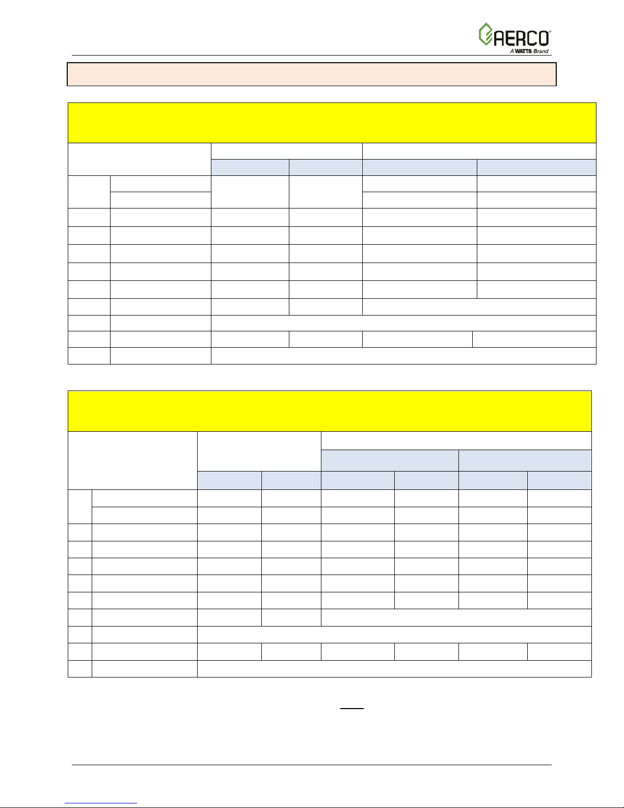
BMK 750
50,000 (14.6 kW)
750,000 (220 kW)
47,750 (14 kW)
716,250 (210 kW)
BMK 1000
50,000 (14.6 kW)
1,000,000 (293 kW)
48,300 (14.15 kW)
968,000 (284 kW)
BMK 1500
75,000 (22 kW)
1,500,000 (440 kW)
64,500 (18.9 kW)
1,395,000 (409 kW)
BMK 2000
100,000 (29.3 kW)
2,000,000 (586 kW)
86,000 (25.2 kW)
1,860,000 (545 kW)
BMK 2500
167,000 (48.9 kW)
2,500,000 (732 kW)
144,000 (42.2 kW)
2,395,000 (702 kW)
BMK 3000
200,000 (58.6 kW)
3,000,000 (879 kW)
174,000 (51.0 kW)
2,874,000 (842 kW)
FORWARD
FOREWORD
The AERCO Benchmark (BMK) 750, 1000, 1500, 2000, 2500, and 3000 natural gas and
propane fueled boilers are modulating and condensing units. They represent a true industry
advance that meets the needs of today's energy and environmental concerns. Designed for
application in any closed loop hydronic system, the Benchmark's modulating capability relates
energy input directly to fluctuating system loads. These BMK models provide extremely high
efficiency operation and are ideally suited for modern low temperature, as well as, conventional
heating systems.
The Benchmark models operate within the following input and output ranges:
IMPORTANT!
Unless otherwise specified:
• all descriptions provided in this document apply to the Benchmark Platinum Series of boiler.
• all measurements apply to both natural gas and propane models, unless otherwise
specified.
BMK PLATINUM BOILER INTAKE and OUTPUT RANGES
BMK
MODEL
The output of the boiler is a function of the unit’s firing rate (valve position) and return water
temperature.
When installed and operated in accordance with this Instruction Manual, these boilers comply
with the NO
(SCAQMD), Rule 1146.2. In addition, the BMK 750 & 1000 comply with the Bay Area Air
Quality Management District regulation 9, Rule 7.
Whether used in singular or modular arrangements, the BMK boilers offer the maximum venting
flexibility with minimum installation space requirements. These boilers are Category II and IV,
positive pressure appliances. Single and/or multiple breeched units are capable of operation in
the following vent configurations:
• Room Combustion Ai r :
• Ducted Combustion Air:
emission standards outlined in: South Coast Air Quality Management District
x
o Vertical Discharg e
o Horizontal Discharge
o Vertical Discharg e
o Horizontal Discharge
INPUT RANGE (BTU/HR.) OUTPUT RANGE (BTU/HR.)
MINIMUM MAXIMUM MINIMUM MAXIMUM
These boilers are capable of being vented utilizing Polypropylene and AL29-4C vent systems.
The Benchmark's advanced electronics are available in several selectable modes of operation
offering the most efficient operating methods and energy management system integration.
OMM-0116_0A AERCO International, Inc. • 100 Oritani Dr. • Blauvelt, NY 10913 Page 5 of 178
GF-201 Ph.: 800-526-0288 03/15/2017
Page 6

BMK 750-3k Platinum Boiler OPERATION, SERVICE, and MAINTENANCE GUIDE
British Thermal Unit. A unit of energy approximately equal to the
A control system developed by AERCO and currently used in all
3
CO
Carbon Monoxide
COMM (Comm)
Communication
Cal.
Calibration
CNTL
Control
Double Block and Bleed, a gas trains containing 2 Safety Shutoff
GF-xxxx
Gas Fired (an AERCO document numbering system)
FORWARD
AERCO Technical Terminology Meanings
TERMINOLOGY MEANING
A (Amp) Ampere
ACS AERCO Control System, AERCO’s boiler management systems
ADDR Address
AGND Anal og Ground
ALRM Alarm
ANSI American National Standards Institute,
ASME American Society of Mechanical Engineers
AUX Auxiliary
BAS
Building Automation System, often used interchangeably with EMS
(see below)
Symbol rate, or simply the number of distinct symbol changes
Baud Rate
(signaling events) transmitted per second. It is not equal to bits per
second, unless each symbol is 1 bit long.
BMK (Benchmark) AERCO’s Benchmark series boilers
BMS or BMS II AERCO Boiler Management Systems
BLDG (Bldg) Building
BST AERCO on-board Boiler Sequencing Technology
BTU
heat required to raise 1 pound (0.45 kg) of water 1°F (0.55 °C)
BTU/HR BTUs per Hour (1 BTU/hr = 0.29 W)
CCP Combination Control Panel
CCS Combination Control System
C-More Controller
(or Control Box)
CFH Cubic Feet per Hour (1 CFH = 0.028 m
Benchmark, Innovation and KC1000 Series product lines.
/hr)
CPU Central Processing Unit
DBB
Valves (SSOVs) and a solenoid operated vent valve.
DIP Dual In-Line Package, a type of switch
ECU Electronic Control Unit (O2 sensor)
EMS Energy Management System; often used interchangeably with BAS
FM Factory Mutual. Used to define boiler gas trains.
Page 6 of 178 AERCO International, Inc. • 100 Oritani Dr. • Blauvelt, NY 10913 OMM-0116_0A
03/15/2017 Ph.: 800-526-0288 GF-201
Page 7

BMK 750-3k Platinum Boiler OPERATION, SERVICE, and MAINTENANCE GUIDE
MBH
1000 BTUs per Hour
duplex data transmission protocol developed by AEG
onAER
P/N
Part Number
POC
Proof of Clos ure
FORWARD
AERCO Technical Terminology Meanings
TERMINOLOGY MEANING
GND Ground
HDR Header
Hex Hexadecimal Number (0 – 9, A – F)
HP Horse Power
HX Heat Exchanger
Hz Hertz (Cycles Per Second)
I.D. Inside Diameter
IGN Ignition
IGST Board Ignition/Stepper Board, contained in C-More Control Box
INTLK (INTL’K) Interlock
I/O Input/Output
I/O Box
IP Internet Protocol
ISO International Organization for Standardization
Lbs. Pounds (1 lb = 0.45 kg)
LED Light Emitting Diode
LN Low Nitrogen Oxide
MA (mA) Milliampere (1 thousandth of an ampere)
MAX (Max) Maximum
MIN (Min) Minimum
Modbus®
NC (N.C.) Normally Closed
NO (N.O.) Normally Open
NOx Nitrogen Oxide
NPT National Pipe T hread
O2 Oxygen
Input/Output (I/O) Box currently used on Benchmark, Innovation and
KC1000 Series products
A serial, half-
Modicon
O.D. Outside Diameter
OMM & O&M Oper ation and Maintenance Manual
AERCO’s on-line remote monitoring system
PCB Printed Circuit Board
PMC Board Primary Micro-Contr oller (PMC) board, contained in the C-More
PPM Part s per Million
PSI Pounds per Square Inch (1 PSI = 6.89 kPa)
OMM-0116_0A AERCO International, Inc. • 100 Oritani Dr. • Blauvelt, NY 10913 Page 7 of 178
GF-201 Ph.: 800-526-0288 03/15/2017
Page 8

BMK 750-3k Platinum Boiler OPERATION, SERVICE, and MAINTENANCE GUIDE
duplex (FDX) transmission of data based
duplex (FDX) transmission of data based
cause invalid data in the
VDC
Volts, Direct Current
VFD
Vacuum Fluorescent Display, also Variable Frequency Drive
W
Watt
W.C.
Water Column, a unit of pressure (1 W.C. = 249 Pa)
FORWARD
AERCO Technical Terminology Meanings
TERMINOLOGY MEANING
PTP Point-to-Point (usually over RS232 networks)
P&T Pressure and Temperature
ProtoNode Hardware interface between BAS and a boiler or water heater
PVC Poly Vinyl Chloride, a common synthetic plastic
PWM Pulse Width Modulation
REF (Ref) Reference
RES. Resistive
RS232
(or EIA-232)
RS422
(or EIA-422)
RS485
(or EIA-485)
RTN (Rtn) Return
SETPT (Setpt) Setpoint Temperature
SHLD (Shld) Shield
SPDT Single Pole Double Throw, a type of switch
SSOV Safety Shut Off Valve
TEMP (Temp) Temperature
Terminating Resistor
Tip-N-Tell A device that indicates if a package was tipped during shipping
UL A business that tests and validates products
VAC Volts, Alternating Current
A standard for serial, full-
on the RS232 Standard
A standard for serial, full-
on the RS422 Standard
A standard for serial, half-duplex (HDX) transmission of data based
on the RS485 Standard
A resistor placed at each end of a daisy-chain or multi-drop network
in order to prevent reflections that may
communication
µA Micro amp (1 millionth of an ampere)
Page 8 of 178 AERCO International, Inc. • 100 Oritani Dr. • Blauvelt, NY 10913 OMM-0116_0A
03/15/2017 Ph.: 800-526-0288 GF-201
Page 9

BMK 750-3k Platinum Boiler OPERATION, SERVICE, and MAINTENANCE GUIDE
SECTION 1: SAFETY PRECAUTIONS
SECTION 1: SAFETY PRECAUTIONS
1.1 WARNINGS & CAUTIONS
Installers and operating personnel MUST, at all times, observe all safety regulations. The
following warnings and cautions are general and must be given the same attention as specific
precautions included in these instructions. In addition to all the requirements included in this
AERCO Instruction Manual, the installation of units MUST conform with local building codes, or,
in the absence of local codes, ANSI Z223.1 (National Fuel Gas Code Publication No. NFPA-54)
for gas-fired boilers and ANSI/NFPASB for LP gas-fired boilers. Where applicable, the
equipment shall be installed in accordance with the current Installation Code for Gas Burning
Appliances and Equipment, CSA B149.1, and applicable Provincial regulations for the class;
which should be carefully followed in all cases. Authorities having jurisdiction should be
consulted before installations are made.
See section 1.4 for important information regarding installation of units within the
Commonwealth of Massachusetts.
IMPORTANT!
This Instruction Manual is an integral part of the product and must be maintained in legible
condition. It must be given to the user by the installer and kept in a safe place for future
reference.
WARNING!
• Do not use matches, candles, flames, or other sources of ignition to check for gas leaks.
• Fluids under pressure may cause injury to personnel or damage to equipment when
released. Be sure to shut off all incoming and outgoing water shutoff valves. Carefully
decrease all trapped pressures to zero before performing maintenance.
• Before attempting to perform any maintenance on the unit, shut off all gas and electrical
inputs to the unit.
• The exhaust vent pipe of the unit operates under a positive pressure and therefore must be
completely sealed to prevent leakage of combustion products into living spaces.
• Electrical voltages up to 120 VAC may be used in this equipment. Therefore the cover on
the unit’s power box (located behind the front panel door) must be installed at all times,
except during maintenance and servicing.
• A three-pole switch must be installed on the electrical supply line of the unit. The switch
must be installed in an easily accessible position to quickly and safely disconnect electrical
service. Do not affix switch to unit sheet metal enclosures.
CAUTION!
• Many soaps used for gas pipe leak testing are corrosive to metals. The piping must be
rinsed thoroughly with clean water after leak checks have been completed.
• DO NOT use this boiler if any part has been under wat er. Call a qualified service technician
to inspect and replace any part that has been under water.
OMM-0116_0A AERCO International, Inc. • 100 Oritani Dr. • Blauvelt, NY 10913 Page 9 of 178
GF-201 Ph.: 800-526-0288 03/15/2017
Page 10
BMK 750-3k Platinum Boiler OPERATION, SERVICE, and MAINTENANCE GUIDE
VALVE
CLOSED
SECTION 1: SAFETY PRECAUTIONS
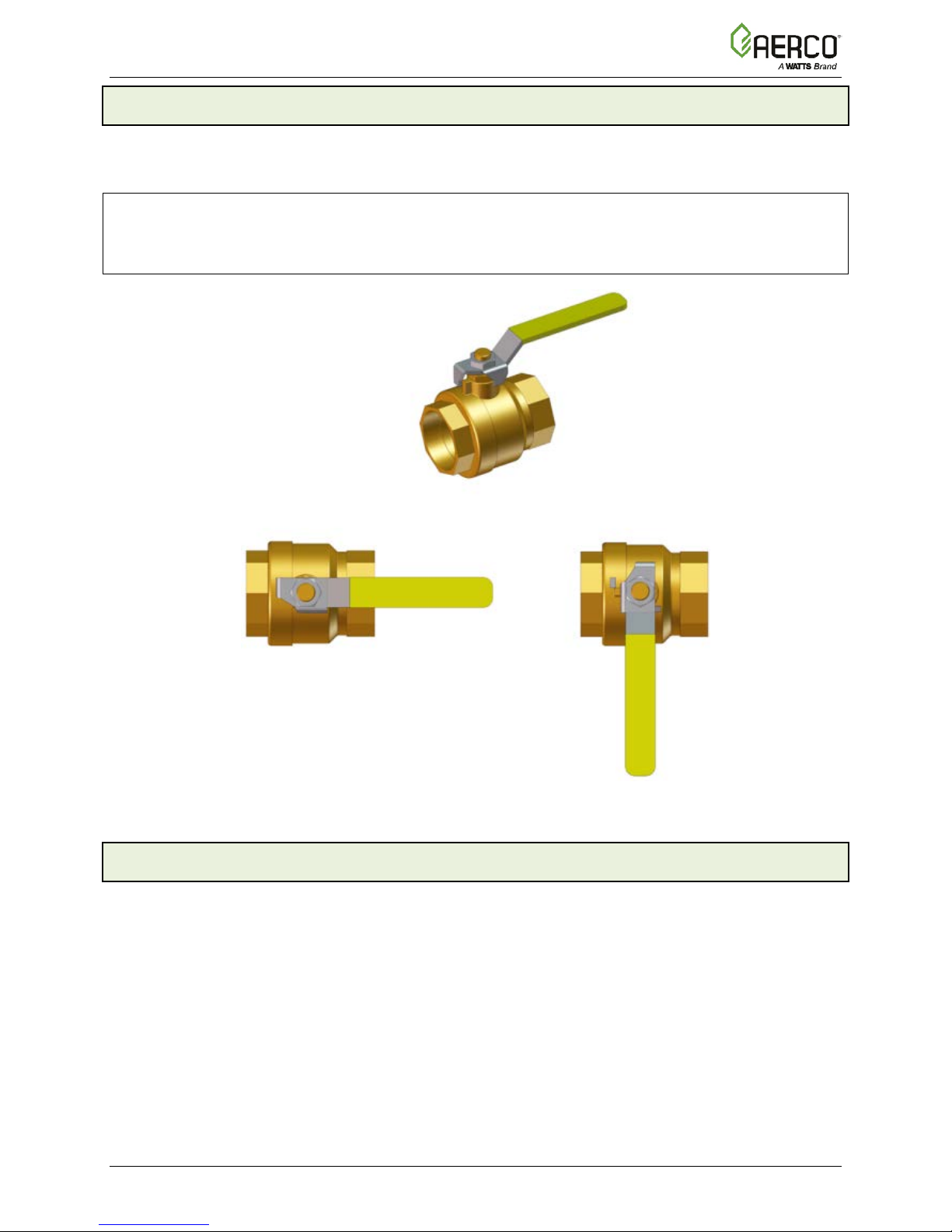
1.2 EMERGENCY SHUTDOWN
If overheating occurs or the gas supply fails to shut off, close the manual gas shutoff valve
(Figure 1-1) located external to the unit.
NOTE:
The Installer must identify and indicate the location of the emergency shutdown manual gas
valve to operating personnel.
MANUAL GAS SHUT-OFF VALVE
VALVE
OPEN
Figure 1-1: Manual Gas Shutoff Valve
1.3 PROLONGED SHUTDOWN
After prolonged shutdown, it is recommended that the startup procedures and safety device test
procedures, described in Section 4 and 5, respectively of the Benchmark 750 – 3000 Installation
and Startup Guide, OMM-0115 (GF-200) be performed to verify all system-operating
parameters. If there is an emergency, turn off the electrical power supply to the AERCO boiler
and close the manual gas valve located upstream the unit. The installer must identify the
emergency shut-off device.
Page 10 of 178 AERCO International, Inc. • 100 Oritani Dr. • Blauvelt, NY 10913 OMM-0116_0A
03/15/2017 Ph.: 800-526-0288 GF-201
Page 11

BMK 750-3k Platinum Boiler OPERATION, SERVICE, and MAINTENANCE GUIDE
REQUIREMENTS FOR MASSACHUSETTS INSTALLATIONS
Boiler Installations within the Commonwealth of Massachusetts must conform to the
(a) For all side wall horizontally vented gas fueled equipment installed in every dwelling,
monoxide detector with an alarm is installed on each additional level of the dwelling,
be the responsibility of the property owner to secure the services of qualified licensed
period, a
Each carbon monoxide detector as
accordance with the above provisions shall comply with NFPA 720 and be
VENT DIRECTLY BELOW. KEEP CLEAR OF ALL OBSTRUCTIONS". (Continued)
SECTION 1: SAFETY PRECAUTIONS
1.4 IMPORTANT – FOR MASSACHUSETTS INSTALLATIONS
following requirements:
• Boiler must be installed by a plumber or a gas fitter who is licensed within the
Commonwealth of Massachusetts.
• Prior to unit operation, the complete gas train and all connections must be leak
tested using a non-corrosive soap.
• The vent termination must be located a minimum of 4 feet above grade level. If
side-wall venting is used, the installation must conform to the following
requirements extracted from 248 CMR 5.08 (2):
building or structure used in whole or in part for residential purposes, including those owned or
operated by the Commonwealth and where the side wall exhaust vent termination is less than
seven (7) feet above finished grade in the area of the venting, including but not limited to decks
and porches, the following requirements shall be satisfied:
1. INSTALLATION OF CARBON MONOXIDE DETECTORS: At the time of installation of the
side wall horizontal vented gas fueled equipment, the installing plumber or gasfitter shall
observe that a hard wired carbon monoxide detector with an alarm and battery back-up is
installed on the floor level where the gas equipment is to be installed. In addition, the
installing plumber or gasfitter shall observe that a battery operated or hard wired carbon
building or structure served by the side wall horizontal vented gas fueled equipment. It shall
professionals for the installation of hard wired carbon monoxide detectors.
a. In the event that the side wall horizontally vented gas fueled equipment is installed in a
crawl space or an attic, the hard wired carbon monoxide detector with alarm and battery
back-up may be installed on the next adjacent floor level.
b. In the event that the requirements of this subdivision can not be met at the time of
completion of installation, the owner shall have a period of thirty (30) days to comply with
the above requirements; provided, however, that during said thirty (30) day
battery operated carbon monoxide detector with an alarm shall be installed.
2. APPROVED CARBON MONOXIDE DETECTORS:
required in
ANSI/UL 2034 listed and IAS certified.
3. SIGNAGE: A metal or plastic identification plate shall be permanently mounted to the
exterior of the building at a minimum height of eight (8) feet above grade directly in line
with the exhaust vent terminal for the horizontally vented gas fueled heating appliance or
equipment. The sign shall read, in print size no less than one-half (1/2) inch in size, "GAS
OMM-0116_0A AERCO International, Inc. • 100 Oritani Dr. • Blauvelt, NY 10913 Page 11 of 178
GF-201 Ph.: 800-526-0288 03/15/2017
Page 12

BMK 750-3k Platinum Boiler OPERATION, SERVICE, and MAINTENANCE GUIDE
REQUIREMENTS FOR MASSACHUSETTS INSTALLATIONS
observes carbon monoxide detectors and signage installed in accordance with the
venting system design or venting system components with the equipment, the instructions
When the manufacturer of a Product Approved side wall horizontally vented gas fueled
2. The "special venting systems" shall be Product Approved by the Board, and the
SECTION 1: SAFETY PRECAUTIONS
4. INSPECTION: The state or local gas inspector of the side wall horizontally vented gas
fueled equipment shall not approve the installation unless, upon inspection, the inspector
provisions of 248 CMR 5.08(2)(a)1 through 4.
(b) EXEMPTIONS: The following equipment is exempt from 248 CMR 5.08(2)(a)1 through 4:
1. The equipment listed in Section 10 entitled "Equipment Not Required To Be Vented" in
the most current edition of NFPA 54 as adopted by the Board; and
2. Product Approved side wall horizontally vented gas fueled equipment installed in a
room or structure separate from the dwelling, building or structure used in whole or in
part for residential purposes.
(c) MANUFACTURER REQUIREMENTS - GAS EQUIPMENT VENTING SYSTEM PROVIDED. When
the manufacturer of Product Approved side wall horizontally vented gas equipment provides a
provided by the manufacturer for installation of the equipment and the venting system shall
include:
1. Detailed instructions for the installation of the venting system design or the venting
system components; and
2. A complete parts list for the venting system design or venting system.
(d) MANUFACTURER REQUIREMENTS - GAS EQUIPMENT VENTING SYSTEM NOT PROVIDED.
equipment does not provide the parts for venting the flue gases, but identifies "special venting
systems", the following requirements shall be satisfied by the manufacturer:
1. The referenced "special venting system" instructions shall be included with the appliance
or equipment installation instructions; and
instructions for that system shall include a parts list and detailed installation instructions.
(e) A copy of all installation instructions for all Product Approved side wall horizontally vented
gas fueled equipment, all venting instructions, all parts lists for venting instructions, and/or all
venting design instructions shall remain with the appliance or equipment at the completion of
the installation.
Page 12 of 178 AERCO International, Inc. • 100 Oritani Dr. • Blauvelt, NY 10913 OMM-0116_0A
03/15/2017 Ph.: 800-526-0288 GF-201
……………….[End of Extracted Information From 248 CMR 5.08 (2)]…………………
Page 13

BMK 750-3k Platinum Boiler OPERATION, SERVICE, and MAINTENANCE GUIDE
SECTION 2: OPERATION
SECTION 2: OPERATION
2.1 INTRODUCTION
The information in this section provides a guide to the operation of the Benchmark Boiler using
the Control Panel mounted on the front of the unit. It is imperative that the initial startup of this
unit be performed by factory trained personnel. Operation prior to initial startup by factory
trained personnel may void the equipment warranty. In addition, the following WARNINGS and
CAUTIONS must be observed at all times.
WARNING!
• ELECTRICAL VO LTAGES IN THIS SYSTEM INCLUDE 120 VAC (BMK 750 – 2000) and
208 or 460 VAC (BMK 2500/3000) and 24 volts AC. It must be serviced only by factory
certified service technicians.
• DO NOT ATTEMPT TO DRY FIRE THE UNIT. Starting the unit without a full water level
can seriously damage the unit and may result in injury to personnel or property damage.
This situation will void any warranty.
CAUTION!
All of the installation procedures in the Benchmark 750 – 3000 Installation and Startup Guide,
OMM-0115 (GF-200) must be completed b efore attempt i ng to start the unit.
OMM-0116_0A AERCO International, Inc. • 100 Oritani Dr. • Blauvelt, NY 10913 Page 13 of 178
GF-201 Ph.: 800-526-0288 03/15/2017
Page 14
BMK 750-3k Platinum Boiler OPERATION, SERVICE, and MAINTENANCE GUIDE
SECTION 2: OPERATION
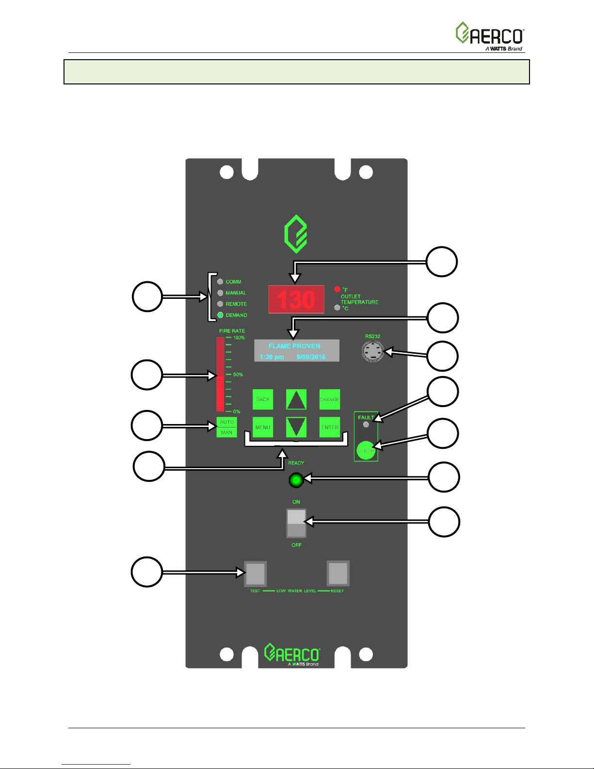
2.2 CONTROL PANEL DESCRIPTION
All Benchmark boilers utilize the C-More Control Panel shown in Figure 2-1. This panel contains
all of the controls, indicators and displays necessary to operate, adjust and troubleshoot the
boiler. These operating controls, indicators and displays are listed and described in Table 2-1.
Additional information on these items is provided in the individual operating procedures and
menu descriptions provided in this section.
2
1
3
12
11
10
9
4
5
6
7
8
Figure 2-1: Control Panel Front View
Page 14 of 178 AERCO International, Inc. • 100 Oritani Dr. • Blauvelt, NY 10913 OMM-0116_0A
03/15/2017 Ph.: 800-526-0288 GF-201
Page 15

BMK 750-3k Platinum Boiler OPERATION, SERVICE, and MAINTENANCE GUIDE
CONTROL, INDICATOR
or DISPLAY
Segment LED display continuously displays the outlet
blinks when operating in the
of displaying up to 16 alphanumeric characters. The information
trained personnel to monitor
communications, in combination with the RS232 Adaptor
124675
LED indicator lights when a boiler alarm condition
be cleared by simply pressing this key. Troubleshooting
8
opens the water level probe circuit and
SECTION 2: OPERATION
TABLE 2-1: CONTROLS, INDICATORS, AND DISPLAYS (ref. Figure 2-1)
ITEM
1
2
FUNCTION
LED STATUS INDICATORS
Four Status LEDs indicate the current operating status as follows:
COMM =
MANUAL =
REMOTE =
DEMAND =
OUTLET
TEMPERATURE
Display
Lights when RS232 communication is occurring – see Item 4.
Lights when the valve position (fire rate) is being controlled using the front
panel keypad. This mode of operation is for service technician use only.
Lights when the unit is being controlled by an external signal from an Energy
Management System.
Lights when there is a demand for heat.
3–Digit, 7–
water temperature. The °F or °C LED next to the display lights to
indicate whether the displayed temperature is in degrees Fahrenheit
or degrees Celsius. The °F or °C
DEADBAND mode.
On a BST Manager, display flashes & shows header temperature.
Vacuum Fluorescent Display (VFD) consists of 2 lines each capable
displayed includes:
3
4
5
6
7
9
VFD Display
RS232 Port
FAULT Indicator
CLEAR Key
READY Indicator
ON/OFF switch
LOW WAT ER
LEVEL
TEST/RESET
switches
• Startup Messages
• Fault Messages
• Operating Status Messages
• Menu Selection
• BST Messages
This port is used only by factoryonAER
Cable (P/N
Red FAULT
occurs. An alarm message will appear in the VFD.
Turns off the FAULT indicator and clears the alarm message if the
alarm is no longer valid. Lockout type alarms will be latched and
cannot
may be required to clear these types of alarms.
Lights when ON/OFF switch is set to ON and when all Pre-Purge
conditions have been satisfied.
Enables and disables boiler operation.
• Allows operator to test operation of the water level monitor.
• Pressing TEST
simulates a Low Water Level alarm.
• Pressing RESET resets the water level monitor circuit.
• Pressing the CLEAR key (item 6) resets the display.
).
OMM-0116_0A AERCO International, Inc. • 100 Oritani Dr. • Blauvelt, NY 10913 Page 15 of 178
GF-201 Ph.: 800-526-0288 03/15/2017
Page 16

BMK 750-3k Platinum Boiler OPERATION, SERVICE, and MAINTENANCE GUIDE
CONTROL, INDICATOR
or DISPLAY
Six (6) keys which provide the following functions for the Control Panel menus:
Allows you to go back to the previous menu level without changing any
information. Continuously pressing this key will bring you back to the
arrow key will
key is
ement the
Saves the modified menu settings in memory. The display will stop
SECTION 2: OPERATION
TABLE 2-1: CONTROLS, INDICATORS, AND DISPLAYS (ref. Figure 2-1)
ITEM
10
MENU
BACK
▲
(UP)
Arrow
▼
(DOWN)
Arrow
CHANGE
FUNCTION
MENU KEYPAD
Steps through the main menu categories shown in Figure 2-2. T he menu
categories wrap around in the order shown.
default status display in the VFD. Also, this key allows you to go back to
the top of a main menu category.
When in one of the main menu categories (Figure 2-2), pressing the ▲
arrow key will select the displayed menu category. If the CHANGE key was
pressed and the menu item is flashing, pressing the ▲
increment the selected setting.
When in one of the main menu categories (Figure 2-2), pressing this key
will select the displayed menu category. If the CHANGE k ey was pressed
and the menu item is flashing, pressing the ▼ arrow key will decrement the
selected setting.
Permits a setting to be changed (edited). When the CHANGE
pressed, the displayed menu item will begin to flash. Pressing the ▲ or ▼
arrow key when the item is flashing will increment or decr
displayed setting.
ENTER
11
12
AUTO/MAN switch
VALVE POSITION
Bargraph
flashing.
This switch toggles the boiler between the AUTOMATIC and
MANUAL modes of operation. When in the MANUAL (MAN) mode,
the front panel controls are enabled and the MANUAL status LED
lights. Manual operation is for service only.
When in the AUTOMATIC (AUTO) mode, the MANUAL status LED
will be off and the front panel controls disabled.
20 segment red LED bargraph continuously shows the Air/Fuel
Valve position in 5% increments from 0 to 100%
Page 16 of 178 AERCO International, Inc. • 100 Oritani Dr. • Blauvelt, NY 10913 OMM-0116_0A
03/15/2017 Ph.: 800-526-0288 GF-201
Page 17

BMK 750-3k Platinum Boiler OPERATION, SERVICE, and MAINTENANCE GUIDE
MENU NAVIGATION and PROCESSING PROCEDURE Instructions
menu and the VFD will display the
menu, which is the next menu
in the
Continue to press the ▲ or ▼ arrow key until the desired menu option is displayed.
SECTION 2: OPERATION
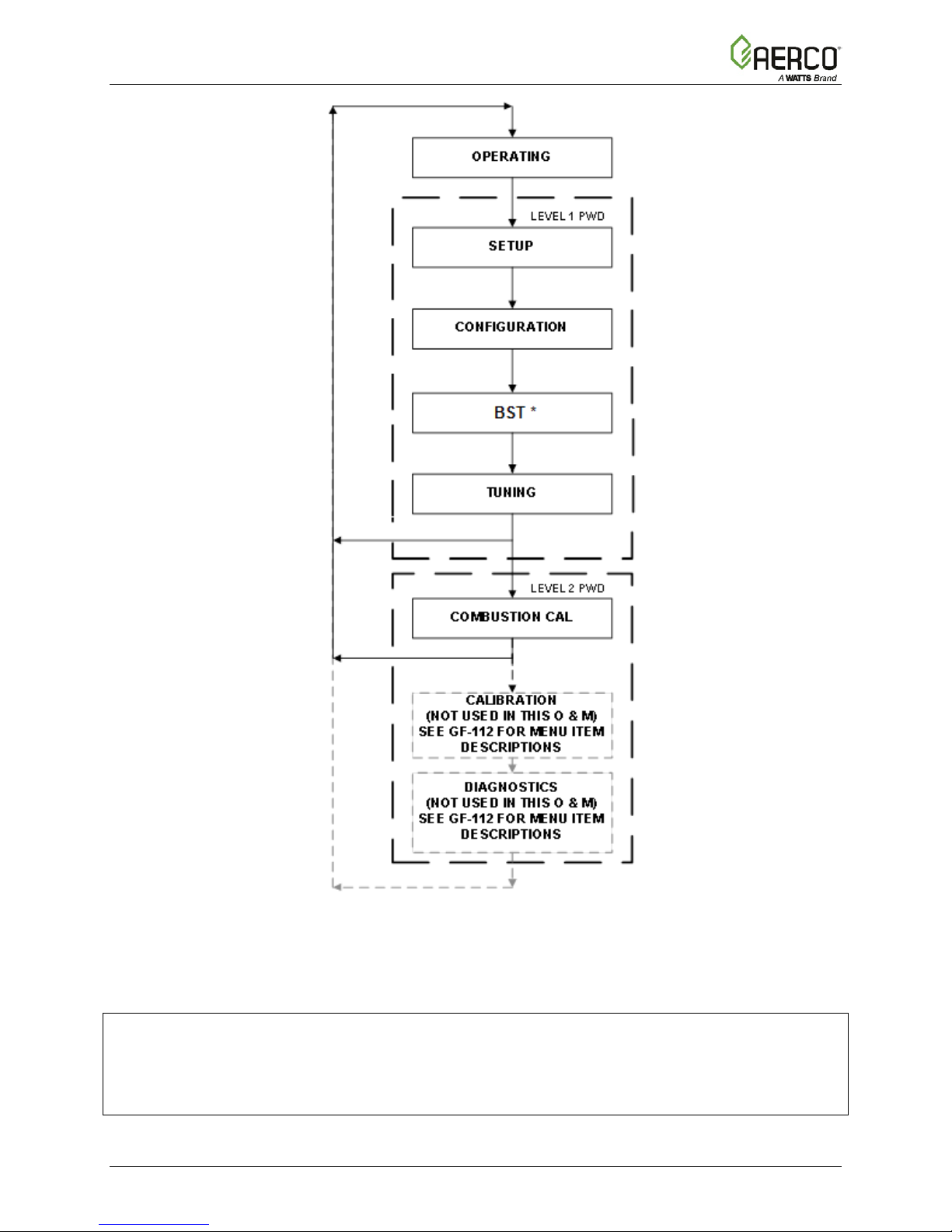
2.3 CONTROL PANEL MENUS
The Control Panel incorporates an extensive menu structure which permits the operator to set
up, and configure the unit. The menu structure consists of five major menu categories which are
applicable to this manual. These categories are shown in Figure 2-2. Each of the menus
shown, contain options which permit operating parameters to be viewed or changed. The
menus are protected by password levels to prevent unauthorized use.
Prior to entering the correct password, the options contained in the Operation, Setup,
Configuration and Tuning menu categories can be viewed. However, with the exception of
Internal Setpoint Temperature (Configuration menu), none of the viewable menu options can be
changed.
Once the valid level 1 password (159) is entered, the options listed in the Setup, Configuration
and Tuning menus can be viewed and changed, if desired. The Combustion Cal menu is
protected by the level 2 password (6817), which is used in initial startup (see Section 4: Initial
Startup of the Benchmark 750 – 3000 I nstallation and Startup Guide, OMM-0115 (GF-200)), to
perform combustion calibration prior to service use.
2.3.1 Menu Navigation and Processing Procedure
Accessing and initiating each menu and option is ac complished using the menu keys shown in
Figure 2-1. Therefore, it is imperative that you be thoroughly familiar with the following basic
steps before attempting to perform specific menu procedures:
1. The Control Panel will normally be in the Operating
current unit status. Pressing the ▲ or ▼ arrow key will display the other available data
items in the Operating menu.
2. Press the MENU key. The display will show the Setup
category shown in Figure 2-2. This menu contains the Password option which must be
entered if other menu options will be changed.
3. Continue pressing the MENU key until the desired menu is displayed.
4. With the desired menu displayed, press the ▲ or ▼ arrow key. The first option
selected menu will be displayed.
5.
Pressing the ▲ arrow key will display the available menu options in the Top-Down
sequence. Pressing the ▼ arrow key will display the options in the Bottom-Up sequence.
The menu options will wrap-around after the first or last available option is reached.
6. To change the value or setting of a displayed menu option, press the CHANGE k ey. The
displayed option will begin to flash. Press the ▲ or ▼ arrow key to scroll through the
available menu option choices for the option to be changed. T he menu option choices do
not wrap around.
7. To select and store a changed menu item, press the ENTER key.
OMM-0116_0A AERCO International, Inc. • 100 Oritani Dr. • Blauvelt, NY 10913 Page 17 of 178
GF-201 Ph.: 800-526-0288 03/15/2017
Page 18
BMK 750-3k Platinum Boiler OPERATION, SERVICE, and MAINTENANCE GUIDE
SECTION 2: OPERATION
* Only if BST is enabled. BST is described in detail in Section 6 of the Benchmark 750 – 3000
Installation and Startup Guide, OMM-0115 (GF-200).
NOTE:
The following sections provide brief descriptions of the options contained in each menu.
Refer to Appendix A for detailed descriptions of each menu option. Refer to Appendix B
for a list and descriptions of startup, status and error messages.
Page 18 of 178 AERCO International, Inc. • 100 Oritani Dr. • Blauvelt, NY 10913 OMM-0116_0A
03/15/2017 Ph.: 800-526-0288 GF-201
Figure 2-2: Menu Structure
Page 19
BMK 750-3k Platinum Boiler OPERATION, SERVICE, and MAINTENANCE GUIDE
AVAILABLE CHOICES OR LIMITS
Minimum
Maximum
30°F (-1.1°C)
240°F (115.6°C)
Ignition Time
SSOV Time to OPN
SECTION 2: OPERATION
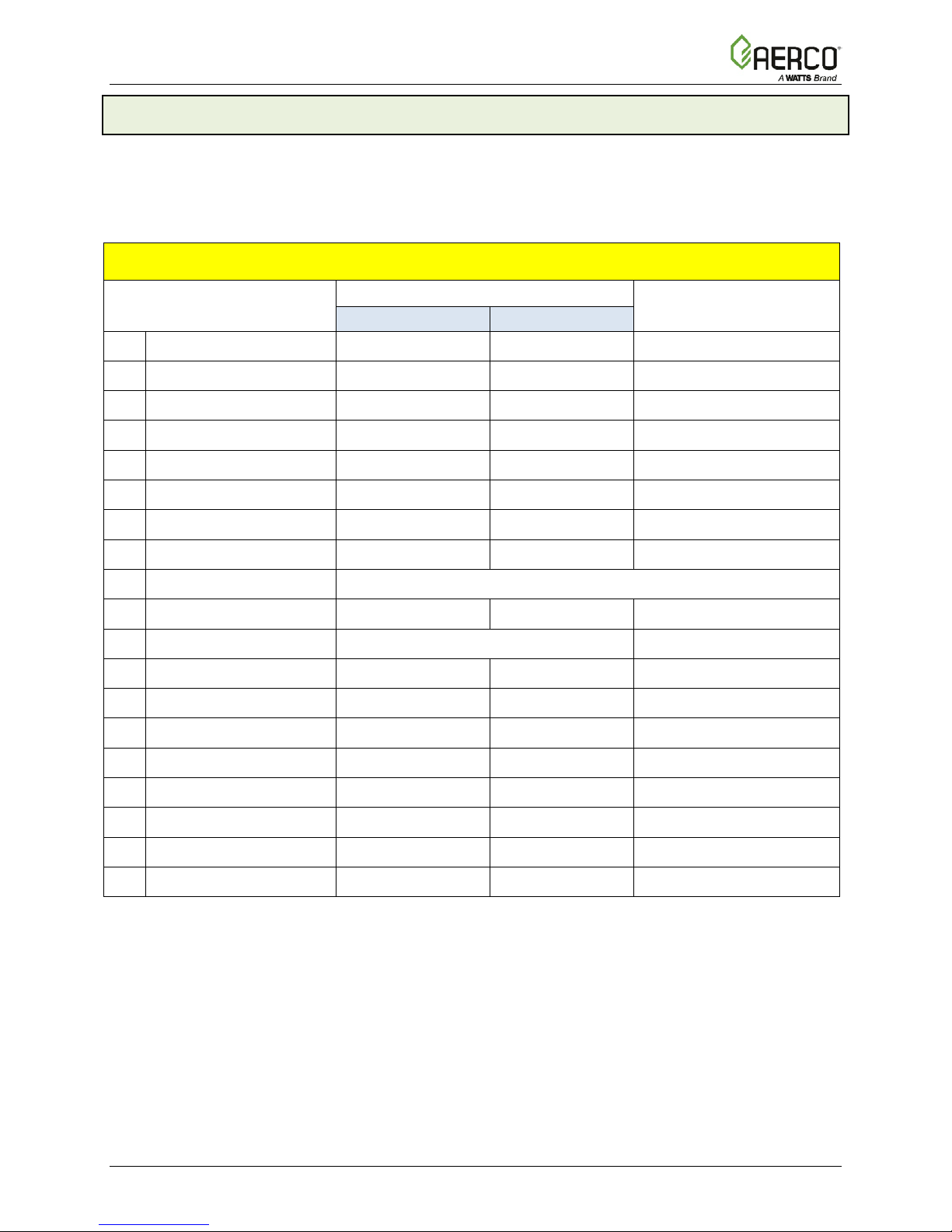
2.4 OPERATING Menu
The Operating menu displays a number of key operating parameters for the unit. All items in this
menu except O2 Monitor (item 15) are “Read-Only” and cannot be changed. This m enu can be
accessed without entering a password.
A full description of each item appears in Appendix A-1.
Table 2-2: OPERATING Menu
MENU ITEM DISPLAY
1
Active Setpoint
2
Outlet Temp
3
Inlet Temp
4
Air Temp
5
Outdoor Temp
6
Valve Position In 0% 100%
7
Valve Position Out 0% 100% Configuration Menu
8
FFWD Temp
9
Exhaust Temp Displays current exhaust temperature
10
Flame Strength 0% 100%
11
Min Flame Str Not Used
12
O2 Monitor Enable Disable O2 Monitor = Enabled
13
Oxygen Level 0% 21%
14
40°F (4.4°C) 240°F (116°C)
30°F (-1.1°C) 240°F (116°C)
30°F (-1.1°C) 240°F (116°C)
-70°F (-56.7°C) 245°F (118°C)
-70°F (-56.7°C) 130°F (54.4°C)
0.00 10.00
Appears Only If
Enabled in:
Configuration Menu
Configuration Menu
15
16
Spark Current
17
Run Cycles 0 999,999,999
18
Run Hours 0 999,999,999
19
Fault Log 0 19
An additional parameter associated with the Operating menu, Manual Valve Pos (Min = 0 , Max
= 100) does not appear in this menu, but can be displayed by pushing the Auto/Man but ton on
the C-More Control Panel’s front face.
OMM-0116_0A AERCO International, Inc. • 100 Oritani Dr. • Blauvelt, NY 10913 Page 19 of 178
GF-201 Ph.: 800-526-0288 03/15/2017
0.00 10.00
0 amps 2.5 amps
Page 20
BMK 750-3k Platinum Boiler OPERATION, SERVICE, and MAINTENANCE GUIDE
AVAILABLE CHOICES OR LIMITS
Minimum
Maximum
2
Language
English
English
3
4
Date
01/01/00
12/31/99
01/01/00
5
6
Comm Address
0
127
0
7
Baud Rate
2400, 4800, 9600, 19.2K
9600
SECTION 2: OPERATION
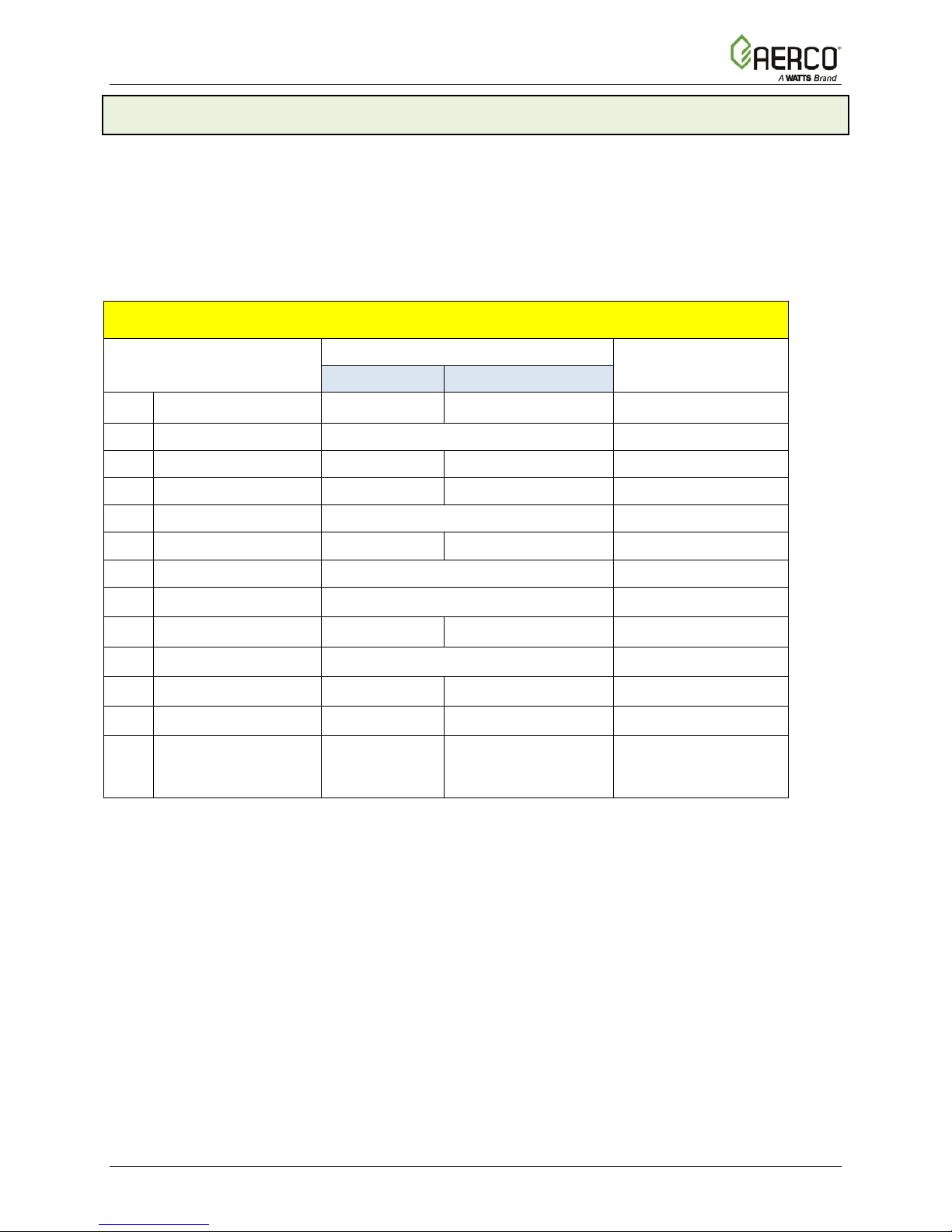
2.5 SETUP Menu
The Setup menu permits the operator to enter the unit password (159) which is required to
change the menu options. To prevent unauthorized use, the password will time-out after 1 hour.
Therefore, the correct password must be reentered when required. In addition to permitting
password entries, the Setup menu is also used to enter date and time, and units of temperature
measurements. A view-only software version display is also provided to indicate the current
Control Box software version.
A full description of each item appears in Appendix A-2.
Table 2-3: SETUP Menu
MENU ITEM DISPLAY
1
Password 0 9999 0
Time 12:00 am 11:59 pm 12:00
Unit of Temp Fahrenheit or Celsius Fahrenheit
8
onAER Mode Et hernet or SD Card Ethernet
9
Min Upload Timer 0 9,999 Sec 0
10
Unit Alpha E, G, H, R, N or A A
11
Unit Year 0 99 0
12
Unit Serial # 0 9999 0
13
Software Ver 0.00 Ver 9.99
DEFAULT
Current software
version
Page 20 of 178 AERCO International, Inc. • 100 Oritani Dr. • Blauvelt, NY 10913 OMM-0116_0A
03/15/2017 Ph.: 800-526-0288 GF-201
Page 21

BMK 750-3k Platinum Boiler OPERATION, SERVICE, and MAINTENANCE GUIDE
Table 2-4: CONFIGURATION Menu
AVAILABLE CHOICES OR LIMITS
Minimum
Maximum
SECTION 2: OPERATION
2.6 CONFIGURATION Menu
The Configuration menu permits adjustment of the Internal Setpoint (Setpt) temperature
regardless of whether the valid password has been entered. Setpt is required for operation in
the CONSTANT SETPOINT mode. The remaining options in this menu require the valid
password to be entered, prior to changing existing entries. This menu contains a number of
other configuration settings which may or may not be displayed, depending on the current
operating mode setting.
A full description of each item appears in Appendix A-3.
NOTE:
The Configuration menu set tings are Factory-Set in accordance with the requirements specified
for each individual order. Under normal operating conditions, no changes will be required.
MENU ITEM DISPLAY
Internal Setpt
1
2
Unit Type
Unit Size
3
(Only displays sizes
available for the unit)
4
Fuel Type
5
Boiler Mode
Remote Signal
(If Mode = Remote
6
Setpoint, Direct Drive
or Combination)
40°F (4.4°C) 240°F (115.6°C)
BMK Blr Std, BMK Blr Std Dual,
BMK Blr LN, BMK Blr LN Dual
750 MBH (220 kW), 1000 MBH (293
kW), 1500 MBH (439.6 kW), 2000 MBH
(586.1 kW), 2500 MBH (732.6 kW), 3000
MBH (879.2 kW)
Natural Gas or Propane
Constant Setpoint, Remote Setpoint,
Direct Drive, Combination,
Outdoor Reset
4 – 20 mA/1 – 5V
0 -20 mA/0 – 5V
PWM Input (Legacy BMS), Network
DEFAULT
130°F (54.4°
BMK Boiler LN
750 MBH (220 kW),
Natural Gas in
standard and dual fuel
models, Propane in
propane only models
Constant Setpoint
4 – 20 mA,
1-5V
C)
7
Outdoor Sensor
* Bldg Ref Temp
8
(If Mode = Outdoor
Reset)
* Reset Ratio
9
(If Mode = Outdoor
Reset)
* System Start Tmp
10
(If Outdoor Sensor =
Enabled)
Setpt Lo Limit
11
OMM-0116_0A AERCO International, Inc. • 100 Oritani Dr. • Blauvelt, NY 10913 Page 21 of 178
GF-201 Ph.: 800-526-0288 03/15/2017
Enabled or Disabled Disabled
40°F
(4.4°C)
0.1 9.9 1.2
30°F
(-1.1°C)
40°F (4.4°C) Setpt Hi Limit 60°F (15.6°C)
230°F
(110°C)
100°F
(37.8°C)
70°F
(21.1°C)
60°F
(15.6°C)
Page 22

BMK 750-3k Platinum Boiler OPERATION, SERVICE, and MAINTENANCE GUIDE
AVAILABLE CHOICES OR LIMITS
Minimum
Maximum
(Do NOT change)
22
SECTION 2: OPERATION
Table 2-4: CONFIGURATION Menu
MENU ITEM DISPLAY
Setpt Hi Limit
12
Temp Hi Limit 40°F (4.4°
13
Max Valve Position
14
Pump Delay Timer
15
Aux Start On Dly
16
Failsafe Mode
17
18
Analog Output
Low Fire Timer
19
Setpt Limiting
20
Setpt Limit Band
21
Network Timeout
Shutoff Dly Temp 0°F (0°C) 25°F (13.75°C) 10°F (5.5°C)
23
Demand Offset
24
Deadband High
25
Setpt Lo Limit 210°F (98.9°C) 180°F (82.2°C)
C) 210°F (98.9°C) 195°F (90.6°C)
40% 100% 100%
0 min. 30 min. 0 min.
0 sec. 120 sec. 0 sec.
Shutdown or Constant Setpt Constant Setpt
Off, Setpoint, Outlet Temp, Valve Pos 4-
Valve Pos 0-10v
20mA, valve Pos 0-10v
2 sec. 600 sec. 2 sec.
Enabled or Disabled Disabled
0°F (0°C) 10°F (5.5°C) 5°F (2.75°C)
5 sec. 999 sec. 30 sec.
0°F (0°C) 25°F ( 13.75°C) 10°F (5.5°C)
0°F (0°C) 25°F ( 13.75°C) 5°F (2.75°C)
DEFAULT
Deadband Low
26
27
IGST Version
28
IGN Time Setting Displays 4 sec. or 7 sec. depending on wiring harness installed
29
Slow Shutdown Enabled or Disabled Disabled
30
Slow Sht Duration 0 sec. 9,999 sec. 60 sec.
Slow Sht Threshold 40% 100% 60
31
O2 Warnings Enabled or Disabled Disabled
32
O2 Trim ID Displays 4 digit AERtrim ID
33
Fixed ID Displays unit’s fixed 4 dig it ID
34
O2 Trim Key Displays AERtrim 4 digit licens e key
35
O2 Trim Menu Enabled or Disabled Disabled
36
37
BST Menu Enabled or Disabled Disabled
0°F (0°C) 25°F ( 13.75°C) 5°F (2.75°C)
Displays current IGST version
V2.02
*NOTE
The Bldg Ref Temp and Reset Ratio menu Items are only displayed when the Outdoor Sensor,
item # 7 is set to Enabled.
CAUTION!
DO NOT change the Analog Output menu item from its default setting (Valve Position 0-10V).
Page 22 of 178 AERCO International, Inc. • 100 Oritani Dr. • Blauvelt, NY 10913 OMM-0116_0A
03/15/2017 Ph.: 800-526-0288 GF-201
Page 23
BMK 750-3k Platinum Boiler OPERATION, SERVICE, and MAINTENANCE GUIDE
Table 2-5: TUNING Menu
AVAILABLE CHOICES OR LIMITS
Minimum
Maximum
2
3
Table 2-6: COMBUSTION CAL Menu: BMK 750/1000
Acceptable Range
Default
Minimum
Maximum
Natural gas
Propane
1
CAL Voltage 18%
0.25
10.00
2.10
2.10
2
CAL Voltage 30%
0.25
10.00
2.55
2.55
3
CAL Voltage 45%
0.25
10.00
3.10
3.10
4
CAL Voltage 60%
0.25
10.00
3.50
3.50
5
CAL Voltage 80%
0.25
10.00
4.60
4.60
6
CAL Voltage 100%
0.25
10.00
5.60
5.60
7
SET Valve Position
0%
100%
0%
0%
8
Blower Output
Monitor Blower Output Voltage
0.00
0.00
9
Set Stdby Volt
0 V
10.0 V
2.00
2.00
10
Oxygen Level
0%
25%
0.0
0.0
SECTION 2: OPERATION
2.7 TUNING Menu
The Tuning menu items are Factory set for each individual unit. Do not change these menu
entries unless specifically requested to do so by factory-trained personnel.
A full description of each item appears in Appendix A-4.
MENU ITEM DISPLAY
1
Prop Band
1°F (0.55°C) 120°F (66°C) 70°F (38.5°C)
DEFAULT
Integral Gain 0.00 2.00 1.00
Derivative Time 0.0 min 2.00 min 0.0min
4
Warmup Prop Band
5
Warmup Int Gain 0.00 2.00 0.50
6
Warmup PID timer 0 sec. 240 sec. 20 sec.
7
Reset Defaults? Yes, No, Are You Sure? No
1°F (0.55°C) 120°F (66°C) 95 °F (52°C)
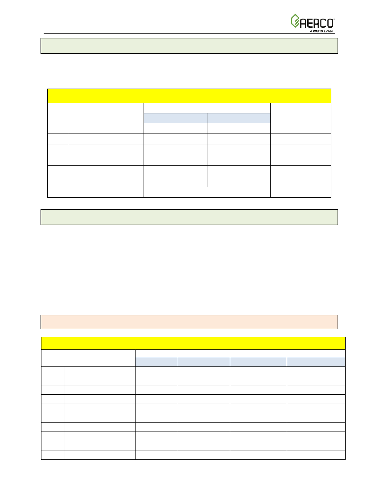
2.8 COMBUSTION CAL Menu
The Com bustion Cal (Calibration) menu is protected by the level 2 password (6817) which must
be entered to view or change the menu items shown in T able 2-6, 2-7 and 2-8. These menu
items are used to vary the speed of the unit’s blower motor based on air temperature and air
density at prescribed Air/Fuel Valve positions (% open). This is accomplished by providing a DC
drive voltage to the motor, which then adjusts the rotational speed of the blower to maximize
combustion efficiency and ensure the unit conforms to the Nitrogen Oxide (NO
Monoxide (CO) emissions specified in the combustion calibration instructions in Section 4.4 of
the Benchmark 750 – 3000 Installation and Startup Guide, OMM-0115 (GF-200).
) and Carbon
x
CAL Voltage values are factory adjusted for each unit prior to shipping, and so may differ from
the defaults shown in the tables below. A full description of each item appears in Appendix A-5.
2.8.1 BMK 750/1000 COMBUSTION CAL Menu
Menu Item Display
OMM-0116_0A AERCO International, Inc. • 100 Oritani Dr. • Blauvelt, NY 10913 Page 23 of 178
GF-201 Ph.: 800-526-0288 03/15/2017
Page 24
BMK 750-3k Platinum Boiler OPERATION, SERVICE, and MAINTENANCE GUIDE
Table 2-7a: COMBUSTION CAL Menu: BMK 1500/2000
SINGLE FUEL – NATURAL GAS
7
8
9
10
Table 2-7b: COMBUSTION CAL Menu: BMK 1500/2000
DUAL FUEL
0.25
10.00
1.50
–
–
0.25
10.00
– – 1.20
2.10
0.25
10.00
3.30
4.50
3.00
4.10
0.25
10.00
4.10
4.80
3.50
4.10
0
100
Variable
Displays current value
9
0
10.0
2.00
2.00
2.00
2.00
SECTION 2: OPERATION
2.8.2 BMK 1500/2000 COMBUSTION CAL Menus
Menu Item Display
CAL Voltage 16%
1
CAL Voltage 18% – 1.40
2
CAL Voltage 30%
3
CAL Voltage 40%
4
CAL Voltage 50%
5
CAL Voltage 70%
6
CAL Voltage 100%
SET Valve Position 0% 100% Variable
Blower Output Displays current value
Set Stdby Volt 0 10.00 V 2.00 V 2.00 V
Oxygen Level Displays current value
Menu Item Display
Acceptable Range Defaults
Minimum Maximum BMK 1500 BMK 2000
0.25 10.00
0.25 10.00 2.30 3.80
0.25 10.00 2.50 4.30
0.25 10.00 2.90 5.40
0.25 10.00 3.80 6.40
0.25 10.00 7.90 9.50
Acceptable Range
NATURAL GAS *
1.80 –
Defaults
PROPANE
CAL Voltage: 16%
1
CAL Voltage: 18%
2
CAL Voltage 30%
3
CAL Voltage 40%
4
CAL Voltage 50%
5
CAL Voltage 70%
6
CAL Voltage 100%
7
SET Valve Position
8
Blower Output
Set Stdby Volt
10
Oxygen Level
Minimum Maximum
0.25 10.00 2.60 4.50 2.30 3.50
0.25 10.00 3.20 4.50 2.80 3.90
0.25 10.00 8.30 9.80 7.70 8.90
BMK 1500 BMK 2000 BMK 1500 BMK 2000
Displays current value
* The default values for Natural Gas on Dual Fuel units are different than the default values for
Natural Gas on Single Fuel units. These values do NOT apply to single fuel units.
Page 24 of 178 AERCO International, Inc. • 100 Oritani Dr. • Blauvelt, NY 10913 OMM-0116_0A
03/15/2017 Ph.: 800-526-0288 GF-201
2.10
Page 25

BMK 750-3k Platinum Boiler OPERATION, SERVICE, and MAINTENANCE GUIDE
Table 2-8a: COMBUSTION CAL Menu: BMK 2500/3000
SINGLE FUEL – NATURAL GAS
7
8
9
10
Table 2-8b: COMBUSTION CAL Menu: BMK 2500/3000 DUAL FUEL
0.25
10.00
–
–
0.25
10.00
– – 2.00
2.30
CAL Voltage: 20%
0.25
10.00
2.10 – –
–
0.25
10.00
5.40
3.30
4.40
3
0.25
10.00
6.60
4.60
5.40
0.25
10.00
6.60
–
5.60
–
0.25
10.00 – – – –
0.25
10.00
8.00
–
7.00
0
100
Variable
8
Displays current value
9
0
10.0
2.00
2.00
2.00
2.00
Displays current value
SECTION 2: OPERATION
2.8.3 BMK 2500/3000 COMBUSTION CAL Menus
MENU ITEM DISPLAY
CAL Voltage 16%
1
CAL Voltage 14% – 2.80
2
CAL Voltage 30%
3
CAL Voltage 40%
4
CAL Voltage 50%
5
CAL Voltage 70%
6
CAL Voltage 100%
SET Valve Position 0% 100% Variable
Blower Output Displays current value
Set Stdby Volt 0 10.00 V 2.00 V 2.00 V
Oxygen Level Displays current value
Menu Item Display
Acceptable range Defaults
Minimum Maximum BMK 2500 BMK 3000
0.25 10.00
0.25 10.00 4.10 4.60
0.25 10.00 4.80 5.00
0.25 10.00 5.30 5.50
0.25 10.00 6.80 6.90
0.25 10.00 8.50 9.10
Acceptable Range
NATURAL GAS *
Minimum Maximum BMK 2500 BMK 3000 BMK 2500 BMK 3000
2.20 –
Defaults
PROPANE
CAL Voltage: 14%
CAL Voltage: 16%
1
CAL Voltage: 18%
CAL Voltage: 22%
2
CAL Voltage 30%
CAL Voltage 45%
4
CAL Voltage 65%
CAL Voltage 70%
5
CAL Voltage 75%
CAL Voltage 85%
6
CAL Voltage 100%
7
SET Valve Position
Blower Output
Set Stdby Volt
10
Oxygen Level
0.25 10.00 –
2.15
0.25 10.00
0.25 10.00 – 7.00 – 5.70
0.25 10.00
–
3.90
5.60
–
8.50
2.40
–
– 2.00 –
8.70 7.90 8.60
– –
* The default values for Natural Gas on Dual Fuel units are different than the default values for
Natural Gas on Single Fuel units. These values shown DO NOT APPLY to single fuel units.
OMM-0116_0A AERCO International, Inc. • 100 Oritani Dr. • Blauvelt, NY 10913 Page 25 of 178
GF-201 Ph.: 800-526-0288 03/15/2017
Page 26
BMK 750-3k Platinum Boiler OPERATION, SERVICE, and MAINTENANCE GUIDE
Table 2-9: BST Menu
1
BST Mode
7
10
12
*BST SETUP MENU*
Disabled
Enabled
Disabled
Remote
Setpoint
Outdoor
Reset
0-20 mA/0-5
VDC
SECTION 2: OPERATION
2.9 BST (Boiler Sequencing Technology) Menu
The BST menu must be enabled in order to be displayed and accessed. The BST Menu item,
located at the end of the Configuration menu (item 37 in Table 2-4), must be set to Enabled.
The BST menu contains all of the items required to configure, operate and monitor the
functionality of the BST System. There are over 50 items in this menu, and selecting any
particular item from the list, for inspection or modification, could be time consuming. As a result,
the BST menu has been segmented into FIVE logical groups based on functionality.
The five Item groups are:
1. BST Monitor Items
2. *BST SETUP MENU*
3. *OPERATE MENU*
4. * TEMP CTRL MENU*
5. * BST COMM MENU*
These displayed item groups are displayed in UPPER CASE letters, and are bounded by an
asterisk * in order to readily identify them within the item list.
The Items contained in group 1 (BST Monitor Items) are always displayed within the menu, as
these items are critical for proper system operation. Therefore, the BST Monitor Items Header
itself is not displayed.
The Items contained in groups 2-5 are not displayed unless that particular item g roup has been
enabled from the C-More keypad.
MENU ITEM DISPLAY
2
BST Setpoint BST Setpt Lo Limit BST Setpt Hi Limit 130°F (54.4°C)
3
Header Temp Read Only – current Header temperature in °F N/A
4
BST Fire Rate 0 100% Fire rate %
5
BST Ave Fire Rate 0 100% Avg Fire Rate %
6
BST Outdoor Temp Read Only – current outdoor temperature in °F N/A
Units Available 0 8 Units Present
8
Units Ignited 0 8 Units firing
9
BST Valve State 0 (CLOSED) 1 (OPEN) 0
1 BST Comm Errors 8 0 9 0
11
1 BST Units 8 0 (see table) 0 (see table) 0
AVAILABLE CHOICES OR LIMITS
DEFAULT
Minimum Maximum
Off BST Client BST Manager Off
13
BST Setpoint Mode
14
BST Remote Signl 4-20 mA/1-5 VDC
15
Head Temp Source Network FFWD Temp FFWD Temp
16
Mdbus Temp Units Degrees C or Degrees F Degrees C
Page 26 of 178 AERCO International, Inc. • 100 Oritani Dr. • Blauvelt, NY 10913 OMM-0116_0A
03/15/2017 Ph.: 800-526-0288 GF-201
Constant Setpoint
Constant Setpt
Network Network
Page 27

BMK 750-3k Platinum Boiler OPERATION, SERVICE, and MAINTENANCE GUIDE
Table 2-9: BST Menu
17
21
Yes
feature.
On-Outlet
Temp
30
*OPERATE MENU*
34
38
42
*TEMP CTRL MENU*
46
50
SECTION 2: OPERATION
MENU ITEM DISPLAY
Header Temp Addr 0 255 240
18
Header Temp Point 0 255 14
19
BST Outdoor Sens Disabled Enabled Disabled
20
Outdr Tmp Source Outdoor Temp Network Outdoor Temp
Outdoor Tmp Addr 0 255 240
22
Outdoor Tmp Pnt 0 255 215
23
BST Auto Mstr No
24
BST Auto Timer 10 sec 120 sec 30 sec
25
Remote Intlk Use Boiler Shutdown System Shutdown System Shutdown
26
One Boiler Mode Off
27
1 Blr Threshold 10 35 25
28
Setpoint Setback Disable Enable Disable
29
Setback Setpoint BST Setpt Lo Limit BST Setpt HI Limit 130°F (54.4°C)
Setback Start 12:00am 11:59pm 12.00am
31
Setback End 12:00am 11:59pm 12.00am
32
Rate Threshold 1°F (0.55°C) 30°F (16.5°C) 15°F (8.25°C)
AVAILABLE CHOICES OR LIMITS
DEFAULT
Minimum Maximum
NOTE! A Modbus
temperature transmitter
must be installed in
conjunction with this
On-Avg Temp Off
No
33
35
36
37
39
40
41
43
44
45
47
48
49
Disabled Enabled Disabled
BST Next On VP 16% 100% 50%
BST Max Boilers 1 8 8
BST On Delay 30 sec 300 sec 60 sec
BST On Timeout 15 sec 300 sec 60 Sec
Valve Override Off Closed Open Off
Valve Off Delay 0 15 min 1 min
BST Sequencing Run Hours Unit Size Select Lead Run Hours
Select Lead Unit 0 127 0
Select Lag Unit 0 127 0
Lead/Lag Hours 25 hours 225 hours 72 hours
Disabled Enabled Disabled
BST Temp Hi Limit 40°F (4.4°C) 210°F (98.9°C) 210°F (98.9°C)
BST Setpt Lo Limit 40°F (4.4°C) BST Setpt HI Limit 60°F (15.5°C)
BST Setpt HI Limit BST Setpt Lo Limit 220°F (104.4°C) 195°F (90.6°C)
BST Prop Band 1°F (-17.2°C) 120°F (48.9°C) 100°F (37.8°C)
BST Intgral Gain 0.00 2.00 0.50
BST Deriv Time 0.00 Min 2.00 Min 0.10 Min
OMM-0116_0A AERCO International, Inc. • 100 Oritani Dr. • Blauvelt, NY 10913 Page 27 of 178
GF-201 Ph.: 800-526-0288 03/15/2017
Page 28

BMK 750-3k Platinum Boiler OPERATION, SERVICE, and MAINTENANCE GUIDE
Table 2-9: BST Menu
51
55
*BST COMM MENU*
59
63
SECTION 2: OPERATION
MENU ITEM DISPLAY
BST Deadband Hi 0 25 1
52
BST Deadband Lo 0 25 1
53
Deadband En Time 0 120 Sec 30 Sec
54
BST FR Up Rate 1 120 20
BST Bldg Ref Tmp 40°F (4.4°C) 230°F (110°C) 70°F (21.1°C)
56
BST Reset Ratio 0.1 9.9 1.2
57
System Start Tmp 30°F (-1.1°C) 120°F (48.9°C) 60°F (15.6°C)
58
Comm Address 0 127 0
60
BST Min Addr 1 128 1
61
BST Max Addr 1 128 8
62
SSD Address 0 250 247
SSD Poll Control 0 1000 0
64
Err Threshold 1 9 5
65
SSD Temp Format Degrees Points Degrees
66
BST Upld Timer 0 9999 sec 0
AVAILABLE CHOICES OR LIMITS
DEFAULT
Minimum Maximum
Disabled Enabled Disabled
Page 28 of 178 AERCO International, Inc. • 100 Oritani Dr. • Blauvelt, NY 10913 OMM-0116_0A
03/15/2017 Ph.: 800-526-0288 GF-201
Page 29

BMK 750-3k Platinum Boiler OPERATION, SERVICE, and MAINTENANCE GUIDE
Table 2-10: Calibration Menu
SECTION 2: OPERATION
2.10 CALIBRATION MENU
The Calibration menu is used by factory trained service personnel to adjust or reset the
parameters listed below.
A full description of each item appears in Appendix A-6.
Menu Item Display
Default
Minimum Maximum
1
Stepper Fbk Cal 0%, Verify 50%, Cal 100% Cal 0%
2
Purge Timer 5 sec. 60 sec Depends on unit type/size
3
Post Purge Timer 0 sec. 60 sec. 0 sec.
4
IGN Position 5% 60% Depends on unit type/size
5
Ign Pos Hold Tmr 0 sec. 60 sec. 0 sec.
6
Available Choices or Limits
FFWD Temp Disply Enabled or Disabled
7
Outlet Tmp Dsply Enabled or Disabled
8
Inlet Tmp Dsply Enabled or Disabled
9
Valv Pos Out Dsp Enabled or Disabled
10
Exhaust Tmp Dsp Enabled or Disabled
11
Exhaust Safety Enabled or Disabled
12
Flue Material
13
Exhst Fault Temp 100 °F 500 °F 200 °F
PVC,CPVC; PolyPro;
Stainless
Disabled
Disabled
Disabled
Enabled
Disabled
Enabled
PVC,CPVC
14
Exhst Module Temp 100 °F 500 °F 190 °F
15
Exhst Warn Temp 100 °F 500 °F 180 °F
16
Exhst Tmp VP Adj 0 10 5
17
Exhst Adj Rate 1 600 30
18
VP Change Rate 5 600 25
19
VP Up Rate 0.5 60.0 Depends on unit type/size
20
VP Down Rate 0.5 60.0 Depends on unit type/size
21
Purge Blwr Offst -1.0 8.0 Depends on unit type/size
22
4-20mA Purge Pct 60% 100% 70%
23
PWM In Adj -5.0% 5.0% 0.0%
24
Analog In Adj
25
Flow In Adj
26
Supply Gas Pressure In Adj -5.0% 5.0% 0.0%
27
Gas Plate dp In Adj -5.0% 5.0% 0.0%
OMM-0116_0A AERCO International, Inc. • 100 Oritani Dr. • Blauvelt, NY 10913 Page 29 of 178
GF-201 Ph.: 800-526-0288 03/15/2017
-5.0% 5.0% 0.0%
-5.0% 5.0% 0.0%
Page 30

BMK 750-3k Platinum Boiler OPERATION, SERVICE, and MAINTENANCE GUIDE
Table 2-10: Calibration Menu
SECTION 2: OPERATION
Menu Item Display
Available Choices or Limits
Minimum Maximum
28
mA Out Adj -1.0 m A 1.0 mA 0.0 mA
29
A/F Sensitivity 1% 5% 2%
30
Power Reset Automatic or Manual Automatic
31
Water Temp Reset Automatic or Manual Automatic
32
Gas Press Reset Automatic or Manual Manual
33
Min Off Time 0 Min 15 Min 1 Min
34
Heatr Tuning Dsp Enabled or Disabled Disabled
35
Heatr Bkpt Dsp Enabled or Disabled Disabled
36
Stop Level 0% Start Level 16
37
Start Level Stop Level 40% 22
38
Skip Range Cntr 10 95 40
39
Skip Range Span 0 3 0%
40
Skip Speed 0.5 2.0 0.5%
41
O2 Gain 0.500 1.500 1.000
Default
42
O2 Offset -24.0 +2.0 1.0
43
O2 Sensor Enabled or Disabled Depends on unit type/size
44
Cal Temp Sensors
45
FFWD Temp Offset -20 +20 0
46
Exhst Tmp Offset -20 +20 0
47
Outdr Air Offset -20 +20 0
48
Inlet Air Offset -20 +20 0
49
Inlet Wtr Offset -20 +20 0
50
Outlet Wtr Offset -20 +20 0
51
24 hr Max Cycles 0 9999 0
52
24 hr Max Ovrtemp 0 9999 0
53
0-10v Out Test 0.0 10.0 0.00
54
Spark Monitor Enabled or Disabled Depends on unit type/size
55
Min Spark Amps 0.0 Amps 2.5 Amps 0.10 Amps
56
Max Spark Amps 0.0 Amps 2.5 Amps 0.40 Amps
Off or Start Off
Page 30 of 178 AERCO International, Inc. • 100 Oritani Dr. • Blauvelt, NY 10913 OMM-0116_0A
03/15/2017 Ph.: 800-526-0288 GF-201
Page 31

BMK 750-3k Platinum Boiler OPERATION, SERVICE, and MAINTENANCE GUIDE
SECTION 3 – MODES OF OPERATION
SECTION 3: MODES OF OPERATION
3.1 INTRODUCTION
The boiler is capable of being operated in any one of six different modes. The following sections
provide descriptions of each of these operating modes. Each boiler is shipped from the factory
tested and configured for the ordered mode of operation. All temperature related parameters
are at their factory default values, which work well in most applications. However, it may be
necessary to change certain parameters to customize the unit to the system environment. After
reading this section, parameters can be customized to suit the needs of the specific application.
A complete listing and descriptions of the temperature related parameters are included in
Appendix A, while factory defaults are listed in Sections 2.4 – 2.10, above.
3.2 INDOOR/OUTDOOR RESET MODE
This mode of operation is based on outside air temperatures. As the outside air temperature
decreases, the supply header temperature will increase and vice versa. For this mode, it is
necessary to install an outside air sensor as well as select a building reference temperature and
a reset ratio.
3.2.1 Reset Ratio
Reset ratio is an adjustable number from 0.1 to 9.9. Once adjusted, the supply header
temperature will increase by that number for each degree that the outside air temperature
decreases. For instance, if a reset ratio of 1.6 is used, for each degree that outside air
temperature decreases the supply header temperature will increase by 1.6 degrees.
3.2.2 Building Reference Temperature
This is a temperature from 40°F to 230°F (4.4°C to 110°C). Once sel e ct ed , it is t h e t em p er a t ur e
that the system references to begin increasing its temperature. For instance, if a reset ratio of
1.6 is used, and we select a building reference temperature of 70°F (21.1°C), then at an outside
temperature of 69°F (20.6°C), the supply header temperature will increase by 1.6° to 71.6°F
(0.9°C to 22°C).
3.2.3 Outdoor Air Temperature Sensor Installation
The outdoor air temperature sensor must be mounted on the North side of the building in an
area where the average outside air temperature is expected. The sensor must be shielded from
the sun's direct rays, as well as direct impingement by the elements. If a cover or shield is used,
it must allow free air circulation. The sensor may be mounted up to 200 feet (61m) fr om the
unit. Sensor connections are made at the Input/Output (I/O) Box on the front of the boiler.
Connections are made at the terminals labeled OUTDOOR AIR IN and AIR SENSOR COM
inside the I/O Box. Use shielded 18 to 22 AWG wire for connections. A wiring diagram is
provided on the cover of the I/O Box. Refer to Section 2.10: AC Electrical Power Wiring of th e
Benchmark 750 – 3000 Installation and Startup Guide, OMM-0115 (GF-200) for additional
information on wiring.
OMM-0116_0A AERCO International, Inc. • 100 Oritani Dr. • Blauvelt, NY 10913 Page 31 of 178
GF-201 Ph.: 800-526-0288 03/15/2017
Page 32

BMK 750-3k Platinum Boiler OPERATION, SERVICE, and MAINTENANCE GUIDE
INDOOR / OUTDOOR SETUP Instructions
Go down the left column of the chart to the coldest design outdoor air temperature
Once the design outdoor air temperature is chosen, go across the chart to the desired
BLDG REF
SECTION 3 – MODES OF OPERATION
3.2.4 Indoor/Outdoor Startup
Startup in the INDOOR/OUT DOOR RESET mode is accomplished as follows:
NOTE:
A design engineer typically provides design outdoor air temperature and supply header
temperature data.
1. Refer to the Indoor/Outdoor reset ratio charts in Appendix E.
2. Choose the chart corresponding to the desired Building Reference Temperature.
3.
expected in your area.
4.
supply header temperature for the design temperature chosen in step 3.
5. Next, go up that column to the RESET RATIO row to find the corresponding reset ratio.
6. Access the Configuration menu and scroll through it until the display shows
TEMP ( Building Reference Temperature). If necessary, refer to Section 2.3: Control Panel
Menus, above, for detailed instructions on navigating the menus.
7. Press the CHANGE key. The display will begin to flash.
8. Use the ▲ and ▼ arrow keys to select the desired Building Reference Temperature.
9. Press ENTER to save any changes.
10. Next, scroll through the Configuration menu until the display shows RESET RATIO.
11. Press the CHANGE key. The display will begin to flash.
12. Use the ▲ and ▼ arrow keys to select the Reset Ratio determined in step 5.
13. Press ENTER to save the change.
3.3 CONSTANT SETPOINT MODE
The CONSTANT SETPOINT mode is used when a fixed header temperature is desired.
Common uses of this mode of operation include water source heat pump loops, and indirect
heat exchangers for potable hot water systems or processes.
No external sensors are required to operate in this mode. While it is necessary to set the
desired setpoint temperature, it is not necessary to change any other temperature-related
functions. The unit is factory preset with settings that work well in most applications. Prior to
changing any temperature-related parameters, other than the setpoint, it is sugg ested that an
AERCO representative be contacted. See Appendix A for des criptions of temperature-related
functions, and Sections 2.4 – 2.10 for their range of values and factory defaults.
Page 32 of 178 AERCO International, Inc. • 100 Oritani Dr. • Blauvelt, NY 10913 OMM-0116_0A
03/15/2017 Ph.: 800-526-0288 GF-201
Page 33

BMK 750-3k Platinum Boiler OPERATION, SERVICE, and MAINTENANCE GUIDE
keys (40°F to 240°F, 4.4°C to 115.6°C)
SECTION 3 – MODES OF OPERATION
3.3.1 Setting the Setpoint
The setpoint temperature of the unit is adjustable from 40°F t o 240°F (4.4°C to 115.6°C). To set
the unit for operation in the CONSTANT SETPOINT mode, you m ust set menu items Internal
Setpt and Boiler Mode in the Configuration menu as follows:
Table 3-1: CONSTANT SETPOINT MODE SETTINGS
MENU OPTION SETTING
Internal Setpt Select desired setpoint using ▲ and ▼ arrow
Boiler Mode Constant Setpoint
See Section 2.3: Control Panel Menus for detailed instructions on changing menu options.
3.4 REMOTE SETPOINT MODES
The unit’s setpoint can be remotely controlled by an Energy Management System (EMS) or
Building Automation System (BAS). The Remote Setpoint can be driven by a current or voltage
signal within the following ranges:
• 4-20 mA/1-5 VDC
• 0-20 mA/0-5 VDC
The factory default setting for t he REMOTE SETPOI NT mode is 4 - 20 mA/1 - 5 VDC. W it h this
setting, a 4 to 20 mA/1 to 5 VDC signal, sent by an EMS or BAS, is used to change the unit's
setpoint. The 4 mA/1V signal is equal to a 40°F (4.4°C) setpoint while a 20 mA /5V signal is
equal to a 240°F (115.6°C) setpoint. When a 0 to 20 mA/0 to 5 VDC signal is used, 0 mA is
equal to a 40°F (4.4°C) setpoint.
In addition to the current and voltage signals described above, the REMOTE SETPOINT mode
can also driven by a RS-485 Modbus Network signal from an EMS or BAS.
The REMOTE SETPOINT modes of operation can be used to drive single as well as multiple
units.
NOTE:
If a voltage, rather than current signal is used to control the remote setpoint, a DIP switch
adjustment must be made on the PMC Board located in the Control Panel Assembly. Contact
your local AERCO representative for details.
In order to enable the REMOTE SETPOINT mode, you must set menu items Boil er Mode and
Remote Signal in the Configuration menu as follows:
Table 3-2: REMOTE SETPOINT MODE SETTINGS
MENU OPTION SETTING
Boiler Mode Remote Setpoint
Remote Signal 4-20mA/1-5V, 0-20mA/0-5V, or Network
Refer to section 2.3: Control Panel Menus for detailed instructions on changing menu options.
OMM-0116_0A AERCO International, Inc. • 100 Oritani Dr. • Blauvelt, NY 10913 Page 33 of 178
GF-201 Ph.: 800-526-0288 03/15/2017
Page 34

BMK 750-3k Platinum Boiler OPERATION, SERVICE, and MAINTENANCE GUIDE
SECTION 3 – MODES OF OPERATION
If the Network setting is selected for RS-485 Modbus operation, a valid Comm Address must be
entered in the Setup menu. Refer to Modbus Communication Manual GF-114 for additional
information.
While it is possible to change the settings of temperature related functions, the unit is factory
preset with settings that work well in most applications. It is suggested that an AERCO
representative be contacted, prior to changing any temperature related function settings. See
Appendix A for descriptions of t emperature-related functions, and Sections 2.4 – 2.10 for their
range of options and factory defaults.
3.4.1 Remote Setpoint Field Wiring
The only wiring connections necessary for the REMOTE SETPOINT mode are connection of the
remote signal leads from the source to the unit’s I/O Box. The I/O Box is located on the front
panel of the boiler. For either a 4-20mA/0-5V or a 0-20mA/0-5V setting, the connections are
made at the ANALOG IN terminals in the I/O Box. For a Network setting, the connections are
made at the RS-485 COMM terminals in the I/O Box. The signal must be floating, (ungrounded)
at the I/O Box and the wire used must be a two wire shielded pair from 18 to 22 AWG. Polarity
must be observed. The source end of the shield must be connected at the source. When driving
multiple units, each unit’s wiring must conform to the above.
3.4.2 Remote Setpoint Startup
Since this mode of operation is factory preset and the setpoint is being ext ernally controlled, no
startup instructions are necessary. In this mode, the REMOTE LED will light when the external
signal is present.
To operate the unit in the MANUAL mode, press the AUTO/MAN switch. T he REMOTE LED
will go off and the MANUAL LED will light.
To change back to the REMOTE SETPOINT mode, simply press the AUTO/MAN swit ch. T he
REMOTE LED will again light and the MANUAL LED will go off.
3.5 DIRECT DRIVE MODES
The unit’s air/fuel valve position (% open) can be changed by a remote signal which is typically
sent from an Energy Management System (EMS) or from a Building Automation System (BAS).
The Direct Drive mode can be driven by a current or voltage signal within the following ranges:
• 4-20 mA/1-5 VDC
• 0-20 mA/0-5 VDC
The fac tor y def ault set ting for t he DIRECT DRIVE mode is 4-2 0 mA /1-5 VDC. With this setting,
a 4 to 20 mA signal, sent by an EMS or BAS is used to change the unit’s valve position from 0%
to 100%. A 4 mA/1V signal is equal to a 0% valve position, while a 20 mA /5V signal is equal to
a 100% valve position. When a 0-20 mA/0 -5 VDC signal is used, zero is equal to a 0% valve
position.
In addition to the current and voltage signals described above, the DIRECT DRIVE mode can
also driven by a RS-485 Modbus Network signal from an EMS or BAS.
When in a DIRECT DRIVE mode, the unit is a slave to the EMS or BAS and does not have a
role in temperature control. DIRECT DRIVE can be used to drive single, or multiple units.
Page 34 of 178 AERCO International, Inc. • 100 Oritani Dr. • Blauvelt, NY 10913 OMM-0116_0A
03/15/2017 Ph.: 800-526-0288 GF-201
Page 35

BMK 750-3k Platinum Boiler OPERATION, SERVICE, and MAINTENANCE GUIDE
SECTION 3 – MODES OF OPERATION
NOTE:
If a voltage, rather than current signal is used to control the remote setpoint, a DIP switch
adjustment must be made on the CPU Board located in the Control Box Assembly. Contact your
local AERCO representative for details.
To enable the DIRECT DRIVE mode, you must set menu items Boiler Mode and Remote
Signal in the Configuration menu as follows:
Table 3-3: DIRECT DRIVE MODE SETTINGS
MENU OPTION SETTING
Boiler Mode Dire c t Drive
Remote Signal 4-20mA/1-5V, 0-20mA/0-5V, or Network
Refer to section 2.3: Control Panel Menus for instructions on changing menu options.
If the Network setting is selected for RS-485 Modbus operation, a valid Comm Address must be
entered in the Setup menu. Refer to Modbus Communication Manual GF-114 for additional
information.
3.5.1 Direct Drive Field Wiring
The only wiring connections necessary for DIRECT DRIVE mode are connection of the remote
signal leads from the source to the unit’s I/O Box. For either a 4-20mA/0-5V or a 0-20mA/0-5V
setting, the connections are made at the ANALOG IN terminals in the I/O Box. For a Network
setting, the connections are made at the RS-485 COMM terminals in the I/O Box. The signal
must be floating, (ungrounded) at the I/O Box and the wire used must be a two wire shielded
pair from 18 to 22 AWG. Polarity must be observed. The source end of the shield must be
connected at the source. When driving multiple units, each unit’s wiring must conform to the
above.
3.5.2 Direct Drive Startup
Since this mode of operation is factory preset and the valve position is being externally
controlled, no startup instructions are necessary. In this mode, the REMOTE LED will ligh t when
the signal is present.
To operate the unit in MANUAL mode, press the AUTO/MAN switch. T he REMOTE LED will go
off and the MANUAL LED will light .
To change back to the Direct Drive mode, simply press the AUTO/MAN swit ch. The REMOTE
LED will again light and the MANUAL LED will go off.
OMM-0116_0A AERCO International, Inc. • 100 Oritani Dr. • Blauvelt, NY 10913 Page 35 of 178
GF-201 Ph.: 800-526-0288 03/15/2017
Page 36

BMK 750-3k Platinum Boiler OPERATION, SERVICE, and MAINTENANCE GUIDE
Remote Signal
Network (RS485)
SECTION 3 – MODES OF OPERATION
3.6 AERCO CONTROL SYSTEM (ACS)
NOTE:
ACS is for installations with 9 or more boilers. It utilizes only RS-485 signaling to the boiler.
Installations with 1 to 8 boilers can use Boiler Sequencing Technology (BST), as described in
Section 6 of the Benchmark 750 – 3000 Installation and Startup Guide, OMM-0115 (GF-200).
The ACS mode of operation is used in conjunction with an AERCO Control System. T he ACS
mode is used when it is desired to operate multiple units in the most efficient manner possible.
For this mode of operation, an ACS Header Sensor must be installed betw een 2 and 10 feet
(0.61 and 3m) downstream of the LAST boiler in the boiler plant's supply water header. The
ACS can control up to 40 boilers; Up to 32 via Modbus (RS-485) network communication. For
ACS programming, operation, and Header Sensor installation details, see ACS Operations
Guide, GF-131. For operation via an RS-485 Modbus network, refer to Modbus Communication
Manual GF-114. To enable the ACS mode, you must set menu items Boiler Mode and Remote
Signal in the Configuration menu as follows:
Table 3-4: ACS MODE SETTINGS
MENU OPTION SETTING
Boiler Mode Direct Drive
Refer to section 2.3: Control Panel Menus for instructions on changing menu options.
3.6.1 ACS External Field Wiring
Wiring connections for RS-485 Modbus control are made between the 485 A- and 485 B+
terminals on t he ACS (boilers 9 through 40) and the RS-485 COMM terminals in the I/O Box on
the front of the boilers.
Wire the units using shielded twisted pair wire between 18 and 22 AWG. Observe the proper
polarity for the ACS RS-485 COMM wiring connections. Shields should be terminated only at
the ACS and the boiler end must be left floating. Each unit’s wiring must conform to the above.
3.6.2 ACS Setup and Startup
This mode of operation is factory preset and the ACS controls the f iring rate (air/fuel valve %
open position). There are no setup instructions for each individual unit.
To operate the unit in MANUAL mode, press the AUTO/MAN switch. The REMOTE LE D will go
off and the MANUAL LED will light
To change back to the ACS mode, simply press the AUTO/MAN switch. The REMOTE LED will
again light and the MANUAL LED will go off.
Page 36 of 178 AERCO International, Inc. • 100 Oritani Dr. • Blauvelt, NY 10913 OMM-0116_0A
03/15/2017 Ph.: 800-526-0288 GF-201
Page 37

BMK 750-3k Platinum Boiler OPERATION, SERVICE, and MAINTENANCE GUIDE
SECTION 3 – MODES OF OPERATION
3.7 COMBINATION CONTROL SYSTEM (CCS)
NOTE:
Only ACS can be utilized for the Combination Control System.
A Combination Control System (CCS) is one that uses multiple boilers to cover both spaceheating and domestic hot water needs. The theory behind this type of system is that the
maximum space-heating load and the maximum domestic hot water load do not occur
simultaneously. Therefore, boilers used for domestic hot water are capable of switching
between constant setpoint and ACS control.
For a typical CCS, an adequate number of boilers are installed to cover the space-heating load
on the design-day. However, one or more units are used for the domestic hot water load as well.
These boilers are the combination units and are referred to as the combo boilers. The combo
boilers heat water to a constant setpoint temperature. That water is then circulated through a
heat exchanger in a domestic hot water storage tank.
Only the AERCO Control System (ACS) is necessary to configure this system if only a single
valve is used to switch from space heating to domestic hot water. However, the ACS Relay
Panel is r equired in combination with the ACS when there are up to two isolation valves, boiler
interlocks, and/or a Domestic Hot Water (DHW) pump in a Combination heating plant where
AERCO boilers are being used for both Building Heat and Domestic Hot Water heating.
The following two options are available for using a combination system; one that uses only the
ACS, and one that requires the optional ACS Relay Box:
• OPTION 1 - T his option is selected when the ACS controls a boiler plant containing up to
eight combination boilers that are Domestic Hot Water Priority (DHW PRIORITY) boilers,
along with building heat (BLDG HEAT) boilers, and one hydronic isolation valve in the main
header between the BLDG HEAT boilers and the DHW PRIORITY boilers.
• OPTION 2 – When t his option is selected, the ACS Relay Panel must be used in conjunction
with the ACS. For this option, the ACS controls a boiler plant containing up to eight
combination boilers that are divided up into Building Priority (BLDG PRIORITY) boilers and
Domestic Hot Water Priority (DHW PRIORITY) boilers, along with building heat (BLDG
HEAT) boilers, and using two hydronic isolation valves in the main header, one between the
BLDG HEAT and BLDG PRIORITY boilers, and the other between the BLDG PRIORITY
and the DHW PRIORITY boilers.
In Option 2, when the space-heating load is such that when all the space-heating boilers are at
the 100% valve position, the ACS will then ask the ACS Relay Box f or the domestic boilers to
become space-heating boilers. Provided the domestic hot water load is satisfied, the combo (hot
water) boilers will then become space-heating boilers. If the domestic hot water load is not
satisfied, the combo boiler(s) remain on the domestic hot water load. If the combo boilers switch
over to space heating, but there is a call for domestic hot water, the ACS Relay Box switches
the combo units back to the domestic load. The ACS in combination with the ACS Relay Box
will ask the BLDG PRIORITY boilers to help with domestic hot water heating if the DHW
PRIORITY boilers are not able to satisfy the domestic hot water demand.
When the combo units are satisfying the domestic load, they are in the CONST ANT SETPOINT
mode of operation. When the combo units switch over to space heating, their mode of operation
changes to follow the ACS command. For more information concerning the operation of the
ACS, consult the ACS Operations Guide, GF-131. For more information on the ACS Relay Box,
see section 2.14 in the same manual.
OMM-0116_0A AERCO International, Inc. • 100 Oritani Dr. • Blauvelt, NY 10913 Page 37 of 178
GF-201 Ph.: 800-526-0288 03/15/2017
Page 38

BMK 750-3k Platinum Boiler OPERATION, SERVICE, and MAINTENANCE GUIDE
SECTION 3 – MODES OF OPERATION
3.7.1 Combination Control System Field Wiring
Wiring for this system is between the ACS, the ACS Relay Box, and the terminals in the I/O
Box. Wire the units using a shielded twisted pair of 18 to 22 AWG wire. When wiring multiple
units, each unit’s wiring must conform to the above.
3.7.2 Combination Control System Setup and Startup
Setup for the COMBINATION mode requires entries to be made in the Configuration menu for
boiler mode, remote signal type and setpoint (see Section 2.6: Configuration Menu f or detai ls).
The setpoint is adjustable from 40°F to 190°F (4.4°C to 87.8°C).
To enable the COMBINATION mode, you must set menu items Boiler M ode, Remote Signal
and Internal Setpt in the Configuration menu as follows:
Table 3-5: COMBINATION MODE SETTINGS
MENU OPTION SETTING
Boiler Mode Combination
Remote Signal Network
Internal Setpt 40°F to 190°F (4.4°C to 87.8°C)
Refer to section 2.3: Control Panel Menus for instructions on changing menu options.
While it is possible to change other temperature-related functions for COMBINATION mode,
these f unctions are preset to their factory default values. These default settings work well in
most applications. It is suggested that AERCO be contacted prior to changing settings other
than the unit’s setpoint. For a complete listing of temperature related function defaults, see
Sections 2.4 – 2.10.
To set the unit to the MANUAL mode, press the AUTO/MAN switch. The MANUAL LED will
light.
To set the unit back to the AUTO mode, press the AUTO/MAN switch. The MANUAL LED will
go off and the REMOTE LED will light.
When the boiler is switched to ACS control, the ACS controls the valve position. There are no
setup requirements to the boiler(s) in this mode.
Page 38 of 178 AERCO International, Inc. • 100 Oritani Dr. • Blauvelt, NY 10913 OMM-0116_0A
03/15/2017 Ph.: 800-526-0288 GF-201
Page 39

BMK 750-3k Platinum Boiler OPERATION, SERVICE, and MAINTENANCE GUIDE
SECTION 4 – AERTRIM OPERATION
SECTION 4: AERTRIM OPERATION
4.1 AERtrim INTRODUCTION
Advanced combustion control systems need to maintain precise air/fuel ratios to maximize
efficiency. Gas and oil-fired boilers often deviate from the ideal air-fuel ratio due to
environmental variations such as humidity, atmospheric pressure, filter dust loading, delivered
gas energy content and other factors. If the boiler is operating with fixed blower/damper
positions, the air/fuel ratio will normally vary within an acceptable level, but will not be fully
optimized for efficiency and reliability.
The AERtrim system is designed to measure and maint ain an ideal air-fuel ratio in Benchmark
boilers, thus maximizing efficiency and reliability while minimizing emissions. It does this by first
measuring post combustion oxygen percentages inside the combustion chamber. This data is
fed through the Electronic Control Unit (ECU) which is connected to the C-More Controller
inside the boiler. If the oxygen readings are outside of preset or user def ined values, the blower
voltage is changed in small increments until the readings fall within the ideal range.
A simplified representation of the system is shown in Figure 4-1.
Sensor ECU
Oxygen Input
CanBus
CanBus
Blower
O2 Sensor
Burner
Combustion Chamber
Voltage Output
C-More Controller
Figure 4-1: Simplified AERtrim Diagram
4.2 AERtrim ACTIVATION
AERtrim is activated at the f actory prior to shipping all Benchmark Platinum boilers. However, if
the C-More control box is changed for any reason, you must activate the AERtrim function by
completing the procedures below. Note that the activation code for each unit is unique, and thus
cannot be transferred to any other unit; if you have multiple units, you must take care to
install the correct code on the correct unit.
OMM-0116_0A AERCO International, Inc. • 100 Oritani Dr. • Blauvelt, NY 10913 Page 39 of 178
GF-201 Ph.: 800-526-0288 03/15/2017
Page 40

BMK 750-3k Platinum Boiler OPERATION, SERVICE, and MAINTENANCE GUIDE
AERtrim ACTIVATION Instructions
SECTION 4 – AERTRIM OPERATION
1. Record the following information from the unit you wish to activate:
• The unit’s Alpha – Year – Serial Number, found on the unit’s code plate. For
example, for a unit built in 2017: G-17-2291, or N-17-0355.
• O
• Fixed ID, found in the Fixed Key in the Configuration Menu (item 34 in Section 2.6).
2. Contact AERCO Sales Administration with the recorded information. They will provide you
with a license key.
Trim ID, found in the O2 Trim Key in the Configuration Menu (item 33 in Section
2
2.6).
3. Once you have obtained the license key, navigate to the O
menu in the C-More and enter the key. The O
Trim menu and AERtrim should
2
automatically enable. If the display does not change to the O
Trim Key in the Configuration
2
Trim menu, something is
2
wrong with the values provided to obtain the key, or with the key itself. Double check your
numbers and Contact Sales Administration for another key.
4. The target O
as needed. However, you must enable the Adjust O2 Trgts option in the O
before you can change these settings.
%, O2 upper range, and lower range are at default values but can be changed
2
Trim menu
2
4.3 OPERATION DETAILS
During operation, the AERtrim system will adjust the command voltage sent to the combustion
air blower within a limited r ange. The amount of voltage trim depends on the error between the
desired O
low limits of blower voltage for each valve position. The total amount of corrective voltage trim
is limited by the controller to insure safe and reliable operation of the system.
The AERtrim system has a rolling active/inactive operation based on 4 hours on / 10 hours off
sequence. Since this is a trim function and not an active control function, the trim activity can
make adjustments in the blower voltage calibration values on the 4/10 schedule to effectively
control the air/fuel mixture without continuous operation of the sensor. This method achieves
the objective for long term efficiency of boiler operation while maximizing t he sensor life in the
boiler environment. The 14 hour cycle insures that the 4 hour on period will be active for any
hour of the day every four days as shown below.
% (target %) and the current reading of the O2 sensor (O2%) and also on high and
2
Figure 4-2: Active O
Page 40 of 178 AERCO International, Inc. • 100 Oritani Dr. • Blauvelt, NY 10913 OMM-0116_0A
03/15/2017 Ph.: 800-526-0288 GF-201
Sensor Cycle Coverage Chart
2
Page 41

BMK 750-3k Platinum Boiler OPERATION, SERVICE, and MAINTENANCE GUIDE
SECTION 4 – AERTRIM OPERATION
Figure 4-3 graphically shows the functional logic of the AERtrim system and how the blower
voltage (BV), O
fixed presets within the controller. The target range is adjustable within these limits to allow the
user to select the optimal air/fuel ratio for a particular boiler or application.
Limits, and air/fuel ratio interact during an AERtrim operation. The limits are
2
Figure 4-3 shows how the controller would react to an O
controller will reduce the blower voltage (BV) until the O
% reading above the upper limit. The
2
% reading is within the Target Range,
2
provided the BV adjustments are within the BV lim its for that unit at that fire rate. The control will
then store this as the new BV calibration setting until changed manually or by another cycle of
the AERtrim function.
NOTE:
When the O2 sensor is off during the 10 hour O2 Sensor OFF periods shown above, Modbus
sends an Oxygen Level of 99 (rather than 0) to building automation system via ProtoNode.
Once th e system operational stability conditions are met, the AERtrim system will execute the
following steps:
1. Lock the fire rate at the current position that needs adjustment to the air/fuel ratio.
2. The Demand LED will flash for at 1Hz to indicate that the trim function has started.
3. Check the oxygen levels inside the combustion chamber:
• If oxygen levels are within the set range, AERtrim releases control.
• If oxygen levels are outside the set range, AERtrim will adjust Blower Voltage to bring
the boiler back to the Target O
This process repeats until the target oxygen range is achieved or the unit reaches the allowable
blower voltage limit.
OMM-0116_0A AERCO International, Inc. • 100 Oritani Dr. • Blauvelt, NY 10913 Page 41 of 178
GF-201 Ph.: 800-526-0288 03/15/2017
Figure 4-3: AERtrim Logic
value.
2
Page 42

BMK 750-3k Platinum Boiler OPERATION, SERVICE, and MAINTENANCE GUIDE
SECTION 4 – AERTRIM OPERATION
4.4 AERtrim AUTO CALIBRATION
AERtrim includes an automatic sensor calibration feature, which helps maintain oxygen sensor
readout accuracy. This feature is disabled by default but may be enabled during AERtrim
activation. Calibration frequency and time adjustments are located in the Auto Cal Freq, and
the Auto Cal Time setting in the O2 Trim menu (see Section 4.5 for details).
Auto Calibration occurs only when the unit is in STANDBY Mode. For example, if the time
and day for an auto calibration passes, the controller will wait for the boiler to cycle off and go
into standby mode before executing the sensor calibration function. If desired, a manual
calibration can be initiated by the user, by enabling the AUTO CAL NOW menu item.
When sensor calibration occurs, the controller starts the O2 Cal Purge for 40 seconds (55
seconds on the BMK 6000) in order to remove residual combustion fumes. Once purged the
controller reads the oxygen level of ambient air used for purging and calculates a calibration
offset between -3 and +3. The offset is applied to correct the sensor reading to the expected air
O
% level of 20.9%. If the calculated offset is more than ± 3%, “O2 Sensor OOR Maintenance
2
Required” will be displayed, and the trim function is disabled. (OOR is used throughout this
manual for Out Of Range)
Page 42 of 178 AERCO International, Inc. • 100 Oritani Dr. • Blauvelt, NY 10913 OMM-0116_0A
03/15/2017 Ph.: 800-526-0288 GF-201
Page 43

BMK 750-3k Platinum Boiler OPERATION, SERVICE, and MAINTENANCE GUIDE
This is available in operating menu. Selecting and enabling O2 Monitoring
O2 Trim
This option enables and disables AERtrim.
Settle Time
The time to set tle blower speed after adjusting the blower voltage.
Trim Gain
The multiplier used to calculate an offset to a blower voltage.
A user can enable or disable this item to show the O2 targets and limit
onAER O2 Time
Timer to send O2 data periodically to AERCO’s onAER or SD card
Trim State
Displays the current state of a trim function.
Fire Rate In
Displays the input fire rate.
Fire Rate Out
Displays the output fire rate.
Displays the calculated blower voltage adjustment after each O2 trim
iteration.
Blower Voltage
Displays the current blower voltage.
Percent Oxygen
Displays the O2 level.
O2 Error1 Codes
Displays O2 error code1. Check Error code in Section 4.7 for more details.
Auto Cal Freq
Select calibration frequency (Never, Monthly, Weekly, Daily)
Auto Cal Time
Enter time of the day to initiate Auto calibration process if active.
Auto Cal Now
Manually enables O2 Auto Calibration using ambient air at 20.9% O2.
Displays the current O2 offset. Default of 1% to account for wet sample
O2 Timer Active
Display the active O2 trim timer.
**O2 Warnings
Enables or Disables all warnings from AERtrim system
SECTION 4 – AERTRIM OPERATION
4.5 AERtrim MENU ITEMS
Most of the menu items below require the level 3 password to access.
TABLE 4-1: AERtrim MENU ITEMS
MENU ITEMS DESCRIPTION
*O2 Monitor
Adjust O2 Target
activates the O2 sensor for 2 hours during the 10 hours O2 off period.
Whenever the O
sensor is enabled this option will be enabled by default.
2
values for adjustment if a change in the O2 curve is desired.
Calc Blo wer Out
O2 Error2 Codes Displays O2 error code2. Check Error code in Section 4.7 for more details.
O2 Offset
value.
*This item is in the top level operating menu
**This item is in the configuration menu
OMM-0116_0A AERCO International, Inc. • 100 Oritani Dr. • Blauvelt, NY 10913 Page 43 of 178
GF-201 Ph.: 800-526-0288 03/15/2017
Page 44

BMK 750-3k Platinum Boiler OPERATION, SERVICE, and MAINTENANCE GUIDE
80%
3%
8%
5.5%
45%
2.35
3.60
3.10
SECTION 4 – AERTRIM OPERATION
4.6 AERtrim MENU VALUES and DEFAULTS
BMK 750 AERtrim VALUES
MENU ITEM MINIMUM MAXIMUM DEFAULT
Settle Time 0 120 Sec 20 Sec
Trim Gain 0.1 5.0 0.250
Max Tries 0 100 15
O2 Target
(must be
between
O
Upper &
2
O
Lower)
2
O2 Lower
Limit
(must be at
least 1%
lower than
O
Upper)
2
O2 Upper
Limit
(must be at
least 1%
higher than
O
Lower)
2
18% 3% 8% 5.5%
30% 3% 8% 5.5%
45% 3% 8% 5.5%
60% 3% 8% 5.5%
100% 3% 8% 5.0%
18% 2.5% 5.5% 4.5%
30% 2.5% 5.5% 4.5%
45% 2.5% 5.5% 4.5%
60% 2.5% 5.5% 5.0%
80% 2.5% 5.5% 5.0%
100% 2.5% 5.5% 4.5%
18% 5.5% 8.5% 6.5%
30% 5.5% 8.5% 6.5%
45% 5.5% 8.5% 6.5%
60% 5.5% 8.5% 6.0%
80% 5.5% 8.5% 6.0%
100% 5.5% 8.5% 5.5%
O2 Offset -3.0 3.0 1.0
BMK 750 AERtrim ADJUSTMENT RANGE
CALIBRATION POINT
18% 1.75 2.85 2.10
30% 1.95 2.60 2.55
60% 3.00 3.90 3.50
80% 3.80 4.75 4.60
100% 4.75 6.00 5.60
Page 44 of 178 AERCO International, Inc. • 100 Oritani Dr. • Blauvelt, NY 10913 OMM-0116_0A
03/15/2017 Ph.: 800-526-0288 GF-201
BLOWER VOLTAGE
Minimum Maximum Default
Page 45

BMK 750-3k Platinum Boiler OPERATION, SERVICE, and MAINTENANCE GUIDE
SECTION 4 – AERTRIM OPERATION
BMK 1000 AERtrim VALUES
MENU ITEM MINIMUM MAXIMUM DEFAULT
Settle Time 0 120 Sec 20 Sec
Trim Gain 0.1 5.0 0.250
Max Tries 0 100 15
18% 3% 8% 5.5%
O2 Target
(must be
between O
Upper & O
Lower)
2
2
O2 Lower
Limit
(must be at le ast
1% lower than
O
Upper)
2
O2 Upper
Limit
(must be at le ast
1% higher than
O
Lower)
2
O2 Offset -3.0 3.0 1.0
30% 3% 8% 5.5%
45% 3% 8% 5.5%
60% 3% 8% 5.5%
80% 3% 8% 5.5%
100% 3% 8% 5.0%
18% 2.5% 5.5% 4.5%
30% 2.5% 5.5% 4.5%
45% 2.5% 5.5% 5.0%
60% 2.5% 5.5% 5.0%
80% 2.5% 5.5% 5.0%
100% 2.5% 5.5% 4.5%
18% 5.5% 8.5% 6.5%
30% 5.5% 8.5% 6.5%
45% 5.5% 8.5% 6.0%
60% 5.5% 8.5% 6.0%
80% 5.5% 8.5% 6.0%
100% 5.5% 8.5% 5.5%
BMK 1000 AERtrim ADJUSTMENT RANGE
CALIBRATION POINT
18% 1.20 2.85 2.10
30% 1.95 2.60 2.55
45% 2.35 3.60 3.10
60% 3.00 3.90 3.50
80% 3.80 4.75 4.60
100% 4.75 6.00 5.60
OMM-0116_0A AERCO International, Inc. • 100 Oritani Dr. • Blauvelt, NY 10913 Page 45 of 178
GF-201 Ph.: 800-526-0288 03/15/2017
BLOWER VOLTAGE
Minimum Maximum Default
Page 46

BMK 750-3k Platinum Boiler OPERATION, SERVICE, and MAINTENANCE GUIDE
SECTION 4 – AERTRIM OPERATION
BMK 1500 AERtrim VALUES
MENU ITEM MINIMUM MAXIMUM DEFAULT
Settle Time 0 120 Sec 20 Sec
Trim Gain 0.1 5.0 0.250
Max Tries 0 100 15
16% 3% 8% 5.5%
O2 Target
(must be
between O
Upper & O
Lower)
2
2
O2 Lower
Limit
(must be at le ast
1% lower than
O
Upper)
2
O2 Upper
Limit
(must be at le ast
1% higher than
O
Lower)
2
O2 Offset -3.0 3.0 1.0
30% 3% 8% 6.5%
40% 3% 8% 6.5%
50% 3% 8% 6.5%
70% 3% 8% 6.0%
100% 3% 8% 5.0%
16% 2.5% 5.5% 5.0%
30% 2.5% 5.5% 5.0%
40% 2.5% 5.5% 5.0%
50% 2.5% 5.5% 5.0%
70% 2.5% 5.5% 5.0%
100% 2.5% 5.5% 4.5%
16% 5.5% 8.5% 6.0%
30% 5.5% 8.5% 7.0%
40% 5.5% 8.5% 7.0%
50% 5.5% 8.5% 7.0%
70% 5.5% 8.5% 6.5%
100% 5.5% 8.5% 5.5%
BMK 1500 AERtrim ADJUSTMENT RANGE
CALIBRATION POINT
16% 1.40 3.30 1.80
30% 1.90 4.60 2.30
40% 2.30 5.70 2.50
50% 2.50 5.70 2.90
70% 2.70 6.30 3.80
100% 6.00 10.00 7.90
Page 46 of 178 AERCO International, Inc. • 100 Oritani Dr. • Blauvelt, NY 10913 OMM-0116_0A
03/15/2017 Ph.: 800-526-0288 GF-201
BLOWER VOLTAGE
Minimum Maximum Default
Page 47

BMK 750-3k Platinum Boiler OPERATION, SERVICE, and MAINTENANCE GUIDE
SECTION 4 – AERTRIM OPERATION
BMK 2000 AERtrim VALUES
MENU ITEM MINIMUM MAXIMUM DEFAULT
Settle Time 0 120 Sec 20 Sec
Trim Gain 0.1 5.0 0.250
Max Tries 0 100 15
18% 3% 8% 6.5%
O2 Target
(must be between
O
Upper & O2
2
Lower)
O2 Lower
(must be at le ast
1% lower than O
Upper)
O2 Upper
(must be at le ast
1% higher than
O
Lower)
2
O2 Offset -3.0 3.0 1.0
30% 3% 8% 6.0%
40% 3% 8% 6.0%
50% 3% 8% 5.5%
70% 3% 8% 5.5%
100% 3% 8% 5.0%
18% 2.5% 5.5% 5.0%
30% 2.5% 5.5% 5.5%
40% 2.5% 5.5% 5.5%
50% 2.5% 5.5% 5.0%
2
70% 2.5% 5.5% 5.0%
100% 2.5% 5.5% 4.5%
18% 5.5% 8.5% 7.0%
30% 5.5% 8.5% 6.5%
40% 5.5% 8.5% 6.5%
50% 5.5% 8.5% 6.0%
70% 5.5% 8.5% 6.0%
100% 5.5% 8.5% 5.5%
BMK 2000 AERtrim ADJUSTMENT RANGE
CALIBRATION POINT
18% 1.90 4.00 1.40
30% 2.70 7.70 3.80
40% 3.00 7.70 4.30
50% 3.30 7.70 5.40
70% 4.00 9.60 6.40
100% 6.00 10.00 9.50
OMM-0116_0A AERCO International, Inc. • 100 Oritani Dr. • Blauvelt, NY 10913 Page 47 of 178
GF-201 Ph.: 800-526-0288 03/15/2017
BLOWER VOLTAGE
Minimum Maximum Default
Page 48

BMK 750-3k Platinum Boiler OPERATION, SERVICE, and MAINTENANCE GUIDE
SECTION 4 – AERTRIM OPERATION
BMK 2500 AERtrim VALUES
MENU ITEM MINIMUM MAXIMUM DEFAULT
Settle Time 0 120 Sec 20 Sec
Trim Gain 0.1 5.0 0.250
Max Tries 0 100 15
16% 3% 8% 5.5%
O2 Target
(must be between
O
Upper & O2
2
Lower)
O2 Lower
(must be at le ast
1% lower than O
Upper)
O2 Upper
(must be at le ast
1% higher than O
Lower)
O2 Offset -3.0 3.0 1.0
30% 3% 8% 6.5%
40% 3% 8% 7.0%
50% 3% 8% 6.0%
70% 3% 8% 6.0%
100% 3% 8% 5.0%
16% 2.5% 5.5% 5.0%
30% 2.5% 5.5% 4.5%
40% 2.5% 5.5% 5.0%
50% 2.5% 5.5% 5.5%
2
70% 2.5% 5.5% 5.5%
100% 2.5% 5.5% 4.5%
16% 5.5% 8.5% 6.0%
30% 5.5% 8.5% 7.0%
40% 5.5% 8.5% 7.5%
50% 5.5% 8.5% 6.5%
2
70% 5.5% 8.5% 6.5%
100% 5.5% 8.5% 5.5%
BMK 2500 AERtrim ADJUSTMENT RANGE
CALIBRATION POINT
16% 1.90 2.90 2.20
30% 3.00 4.90 4.10
40% 3.70 5.90 4.80
50% 4.20 6.40 5.30
70% 5.20 8.40 6.80
100% 6.50 9.20 8.50
Page 48 of 178 AERCO International, Inc. • 100 Oritani Dr. • Blauvelt, NY 10913 OMM-0116_0A
03/15/2017 Ph.: 800-526-0288 GF-201
BLOWER VOLTAGE
Minimum Maximum Default
Page 49

BMK 750-3k Platinum Boiler OPERATION, SERVICE, and MAINTENANCE GUIDE
SECTION 4 – AERTRIM OPERATION
BMK 3000 AERtrim VALUES
MENU ITEM MINIMUM MAXIMUM DEFAULT
Settle Time 0 120 Sec 20 Sec
Trim Gain 0.1 5.0 0.250
Max Tries 0 100 15
14% 3% 8% 6.5%
O2 Target
(must be
between O
Upper & O
Lower)
2
2
O2 Lower
(must be at le ast
1% lower than
O
Upper)
2
O2 Upper
(must be at le ast
1% higher than
O
Lower)
2
O2 Offset -3.0 3.0 1.0
30% 3% 8% 7.3%
40% 3% 8% 7.5%
50% 3% 8% 7.0%
70% 3% 8% 5.5%
100% 3% 8% 5.0%
14% 2.5% 5.5% 5.5%
30% 2.5% 5.5% 5.5%
40% 2.5% 5.5% 5.5%
50% 2.5% 5.5% 5.5%
70% 2.5% 5.5% 5.0%
100% 2.5% 5.5% 4.5%
14% 5.5% 8.5% 7.0%
30% 5.5% 8.5% 7.8%
40% 5.5% 8.5% 8.0%
50% 5.5% 8.5% 7.5%
70% 5.5% 8.5% 6.0%
100% 5.5% 8.5% 5.5%
BMK 3000 AERtrim ADJUSTMENT RANGE
BLOWER VOLTAGE
CALIBRATION POINT
Minimum Maximum Default
14% 2.60 4.90 2.80
30% 3.60 7.00 4.60
40% 4.60 8.00 5.00
50% 5.00 9.20 5.50
70% 6.10 10.00 6.90
100% 7.60 10.00 9.10
OMM-0116_0A AERCO International, Inc. • 100 Oritani Dr. • Blauvelt, NY 10913 Page 49 of 178
GF-201 Ph.: 800-526-0288 03/15/2017
Page 50

BMK 750-3k Platinum Boiler OPERATION, SERVICE, and MAINTENANCE GUIDE
O2 Offset too low – Increase
Offset value
Gas Pressure Regulator or Air
Combustion Calibration
SECTION 4 – AERTRIM OPERATION
4.7 AERtrim MAINTENANCE and TROUBLESHOOTING
The AERtrim system, which maximizes blower efficiency, depends on the O2 sensor. The
AERtrim system needs only minimal maintenance. It is recommended that you inspect the
oxygen sensor for accuracy every 12 months by comparing it to a sensor reading from a
properly calibrated flue analyzer. This is strongly advised because contaminated air or gas
supplies may cause impurity buildup and shift the calibration point. An offset value of ±3% can
be entered in the Trim menu to correct the reading during manual calibration. If the sensor has a
large amount of offset, a replacement may be required soon.
Occasional software updates to the device may be required. See TID-0156 for sensor
replacement instructions and the software update procedure.
Table 4-2: AERtrim GENERAL WARNINGS
WARNING CAUSE POSSIBLE SOLUTIONS
Dirty filter or poor combustion
calibration – recalibrate unit
O2 PERCENTAGE LOW
O
Levels less than 2% for more than
2
30 seconds {auto-r eset wh en valve
comes back in range}
O2 SENSOR
MALFUNCTION
WARNING 02 LEVEL
HIGH
O2 SENSOR OOR
MAINT REQUIRED
(OutOfRange)
O2 WARNING SERVICE
REQUIRED
Levels less than -4% or more than
O
2
24% for more than 10 seconds {manual
clearing of this fault is required}
Levels > 9% and < 24% for more
O
2
than 30 seconds {auto-reset when
value comes back in range}
Sensor auto calibration offset required
is more than ±3%
If the O
more than 5 minutes.
For example:
1) Reading < Lower Limit
& Blower Voltag e = BV Limit
OR
2) Reading > Upper Limit
& Blower Voltag e = BV Limit
level is outside of its limits for
2
Bad Sensor-Replace
Bad Sensor-Replace
Communication Issue – check
wires and connections
Blower Problem, or bad
O2 Offset too high
Bad Sensor-Replace
Reset Unit-Recalibrate Sensor
Bad Sensor-Replace
Bad ECU-Replace (Rare)
Gas Supply, Air Filter, or Air
Blower issue
Bad Sensor-Replace
The C-More does not display a message when O
O
levels fall outside the target range, one of the messages listed in Table 4-2 will be displayed
2
when you view the Trim State menu item in the O2 Trim menu.
Page 50 of 178 AERCO International, Inc. • 100 Oritani Dr. • Blauvelt, NY 10913 OMM-0116_0A
03/15/2017 Ph.: 800-526-0288 GF-201
levels are within the target range. However, if
2
Page 51

BMK 750-3k Platinum Boiler OPERATION, SERVICE, and MAINTENANCE GUIDE
Table 4-3: AERtrim OPERATION INTERRUPTION ERRORS
SECTION 4 – AERTRIM OPERATION
ERROR MESSAGE CAUSE POSSIBLE SOLUTIO NS
BV Hi Err
BV Lo Err
Max Iter
Tmp Rng Err
FR Rng Err
Trim operation exceeds allowable
blower voltage limits
Trim Operation reached maximum
iteration. Wait and try again
Outlet temp is outside of
temperature range
Fire Rate is not within track range
during trim operation
Check air filter, gas regulator,
combustion calibration
Check sensor calibration; it may
need to be replaced
Check sensor calibration for
inaccuracies
Increase gain or iteration attempts
None-Normal Operation
None – Steady State has not been
achieved
OMM-0116_0A AERCO International, Inc. • 100 Oritani Dr. • Blauvelt, NY 10913 Page 51 of 178
GF-201 Ph.: 800-526-0288 03/15/2017
Page 52

BMK 750-3k Platinum Boiler OPERATION, SERVICE, and MAINTENANCE GUIDE
SECTION 4 – AERTRIM OPERATION
(This page intentionally blank)
Page 52 of 178 AERCO International, Inc. • 100 Oritani Dr. • Blauvelt, NY 10913 OMM-0116_0A
03/15/2017 Ph.: 800-526-0288 GF-201
Page 53

BMK 750-3k Platinum Boiler OPERATION, SERVICE, and MAINTENANCE GUIDE
LABOR
TIME
Igniter-Injector Kit (P/N
58023)
Inspect, replace
if necessary
Flame Detector Kit
(P/N 24356-1)
Inspect, replace
if necessary
Lean O2 Sensor
(P/N 61026)
**
Combustion Calibration
*Check
Check
1 hr.
See ASME
CSD-1 Chart
6.7
Burner
Inspect
2 hrs.
Inspect, Clean &
Gaskets
Inspect, Clean
Gaskets
6.9
SECTION 5 – MAINTENANCE
SECTION 5: MAINTENANCE
5.1 MAINTENANCE SCHEDULE
All Benchmark boilers require regular routine maintenance to keep up efficiency and reliability.
For best operation and life of the unit, the following routine maintenance procedures should be
performed in the time periods specified in Table 5-1. For a complete inspection check list see
ASME CSD-1 chart. In order to perform the maintenance tasks specified in Table 5-1, the
following maintenance kits are available through your local AERCO Sales Representative:
• 12 Month Maintenance Kit: P/N 58025-01
• 24-Month Waterside/Fireside Inspection Kit:
o BMK 750/1000: P/N 58025-08
o BMK 1500/2000: P/N 58025-13
o BMK 2500/3000: P/N 58025-10
NOTE:
The 24-Month Waterside/Fireside Inspection Kit also includes the items contained in the Annual
Maintenance Kit (P/N 58025-01). Therefore, only the 24-Month kit is required when performing
the waterside/fireside inspections. Refer to Appendix L for recommended spare parts.
WARNING!
Prior to servicing ensure that the following guidelines are strictly observed:
• Disconnect the AC power supply by turning off the service switch and ac supply circuit
breaker.
• Shut off the gas supply at the manual shut-off valve provided with the unit
• Allow the unit to cool to a safe water temperature to prevent burning or scalding
Table 5-1: MAINTENANCE SCHEDULE
SEC
6.2
6.3
6.4
6.6
Testing of Safety Devices
ITEM 6 MOS. 12 MOS. 24 MOS.
*Inspect
*Inspect
*Inspect Inspect 15 mins.
Replace 15 mins.
Replace 15 mins.
45 mins.
6.8
Condensate Drain Trap *Inspect
Air Filter Clean Replace 15 mins.
* Only performed after initial 6 month period after initial startup.
** Combustion Calibration instructions are in Section 4.4 of OMM-0115 (GF-200)
OMM-0116_0A AERCO International, Inc. • 100 Oritani Dr. • Blauvelt, NY 10913 Page 53 of 178
GF-201 Ph.: 800-526-0288 03/15/2017
Replace
& Replace
30 mins.
Page 54

BMK 750-3k Platinum Boiler OPERATION, SERVICE, and MAINTENANCE GUIDE
STAGED IGNITION
SOLENOID
STAGED IGNITION
ASSEMBLY
O2 SENSOR
BURNER PLATE
BURNER
AIR/FUEL VALVE
BLOWER
IGNITER-INJECTOR
FLAME DETECTOR
GAS FLEX HOSE
BLOWER PROOF SWITCH
BLOCKED INLET SWITCH
SECTION 5 – MAINTENANCE
5.2 IGNITER-INJECTOR
The igniter-injector (Kit P/N 58023) is located on the burner plate at the top of the boiler. In
addition to providing the ignition spark required to light the burner, the igniter-injector also
contains a gas injector tube which connects to the staged ignition assembly. Figure 5-1a
through Figure 5-1c shows the complete burner assembly removed from the boiler and indicates
the location of the igniter-injector flame detector and other related components.
Figure 5-1a: BMK 750/1000 Burner Assembly (Removed from Boiler)
Page 54 of 178 AERCO International, Inc. • 100 Oritani Dr. • Blauvelt, NY 10913 OMM-0116_0A
03/15/2017 Ph.: 800-526-0288 GF-201
Page 55

BMK 750-3k Platinum Boiler OPERATION, SERVICE, and MAINTENANCE GUIDE
BLOWER
BLOWER
IGNITER-
FLAME
PORT
AIR/FUEL
VALVE
LEAN O2 SENSOR
A/F VALVE
FLAME
DETECTOR
BURNER
FLAME OBSERVATION PORT
AIR/FUEL
VALVE
BLOCKED
A/F VALVE
SECTION 5 – MAINTENANCE
PLENUM
INJECTOR
ASSEMBLY
BLOCKED
INLET
SWITCH
PLENUM
PLENUM FLANGE/
BURNER TOP PLATE
BURNER
Figure 5-1b: BMK 1500/2000 Burner Assembly (Removed from Boiler)
BLOWER
BLOWER
PLENUM
LEAN O2 SENSOR
BURNER
PLATE FLANGE
FLAME
DETECTOR
OBSERVATION
PLENUM
IGNITOR-INJECTOR
ASSEMBLY
Figure 5-1c: BMK 2500/3000 Burner Assembly (Removed from Boiler)
OMM-0116_0A AERCO International, Inc. • 100 Oritani Dr. • Blauvelt, NY 10913 Page 55 of 178
GF-201 Ph.: 800-526-0288 03/15/2017
INLET
SWITCH
Page 56

BMK 750-3k Platinum Boiler OPERATION, SERVICE, and MAINTENANCE GUIDE
IGNITER-INJECTOR MAINTENANCE PROCEDURE Instructions
LEAN O2 SENSOR
STAGED
IGNITER-INJECTOR
INDEXING
(0-3 as required)
FLAME
BURNER
STAGED
FLAME
INJECTOR-IGNITER
(0-3 as needed)
LEAN O2 SENSOR
BLOWER
PLENUM
COMPRESSION
SECTION 5 – MAINTENANCE
The igniter-injector may be hot, therefore, care should be exercised to avoid burns. It is easier to
remove the igniter-injector from the unit after the unit has cooled to room temperature. To
inspect/replace the Igniter:
1. Set the ON/OFF switch on the control panel to the OFF position. Disconnect AC power
from the unit
2. Remove the top shroud from the unit by grasping the top handle and lifting straight up. This
will disengage the shroud from the four (4) pins in the side panels.
3. Disconnect the cable from the igniter-injector (see Figure 5-1a – Figure 5.1c, above).
4. Referring to Figure 5-2a – Figure 5.2c, below, use a 7/16” open-end wrench to disconnect
the compression nut securing the gas injector tube of the igniter-injector to the elbow of the
staged ignition assembly. Disconnect the staged ignition assembly from the igniter-injector.
DETECTOR
& GASKET
PLATE
& WASHER
IGNITION
SOLENOID
(CLOCKING)
WASHERS
Figure 5-2a: BMK 750/1000 Igniter-Injector & Flame Detector Mounting Detail s
FITTING & ELBOW
IGNITION
SOLENOID
ASSY WITH INDEXING
(CLOCKING) WASHERS
& WASHER
BURNER PLATE
FLANGE
Figure 5-2b: BMK 1500/2000 Igniter-Injector & Flame Detector Mounting Details
Page 56 of 178 AERCO International, Inc. • 100 Oritani Dr. • Blauvelt, NY 10913 OMM-0116_0A
03/15/2017 Ph.: 800-526-0288 GF-201
FLAME
OBSERVATION
PORT
DETECTOR &
GASKET
Page 57

BMK 750-3k Platinum Boiler OPERATION, SERVICE, and MAINTENANCE GUIDE
IGNITER-INJECTOR MAINTENANCE PROCEDURE Instructions
ld be replaced. If carbon
injector by
FLAME
FLAME
INJECTOR-IGNITOR
(0-3 as needed)
FLEX GAS
COMPRESSION
BLOWER
PLENUM
SECTION 5 – MAINTENANCE
STAGED IGNITION
FITTING &
ELBOW
O2 SENSOR
& WASHER
SOLENOID
DETECTOR &
GASKET
HOSE NIPPLE
OBSERVATION
ASSY WITH INDEXING
(CLOCKING) WASHERS
Figure 5-2c: BMK 2500/3000 Igniter-Injector & Flame Detector Mounting Details
BURNER PLATE
FLANGE
PORT
5. Next, loosen and remove the igniter-injector from the burner plate using a 1" open-end
wrench.
6. Check the igniter-injector for evidence of erosion or carbon build-up. If there is evidence of
substantial erosion or carbon build-up, the igniter-injector shou
build-up is present, clean the component using fine emery cloth. Repeated carbon build-up
is an indication that the combustion settings of the unit should be checked. To review
combustion calibration procedures, refer to Section 4.4 of the Benchmark 750 – 3000
Installation and Startup Guide, OMM-0115 (GF-200).
7. Prior to reinstalling the igniter-injector, apply a high temperature, conductive, anti-seize
compound to the threads.
8. Reinstall the igniter-injector in the burner plate using 1 to 3 indexing washers, as needed,
so that when the igniter-injector is tightened, its injector tube will be positioned within the
approximately 120° arc shown in Figure 5-3a throug h 5 -3c, below. Note, the recommended
injection tube positioning differs for the positioning recommended in the past.
9. Torque the igniter-injector to 170 - 180 in-lbs (19.2 – 20.3 Nm). DO NOT over tighten.
NOTE:
If a replacement igniter-injector (Kit P/N 58023) is being installed, a compression nut
containing a built-in ferrule and 3 indexing washers are included with the kit.
10. Connect the staged ignition assembly to the gas injector tube of the igniter-
securing the compression nut to the elbow of the staged ignition assembly.
11. Reconnect the igniter-injector cable.
12. Reinstall the shroud on the unit.
OMM-0116_0A AERCO International, Inc. • 100 Oritani Dr. • Blauvelt, NY 10913 Page 57 of 178
GF-201 Ph.: 800-526-0288 03/15/2017
Page 58

BMK 750-3k Platinum Boiler OPERATION, SERVICE, and MAINTENANCE GUIDE
IGNITER-INJECTOR MAINTENANCE PROCEDURE Instructions
IGNITER-INJECTOR
INJECTOR TUBE
BURNER PLATE
BLOWER
FLAME
O2 SENSOR
IGNITER-INJECTOR
POSITION
POSITION
INJECTOR TUBE
IGNITER-INJECTOR
INJECTOR TUBE
POSITION
SECTION 5 – MAINTENANCE
INJECTOR TUBE
INSIDE THIS ARC
Figure 5-3a: BMK 750/1000 Igniter-Injector Orientation
INJECTOR TUBE
INSIDE THIS ARC
DETECTOR
FLAME
OBSERVATION
O2 SENSOR
PORT
Figure 5-3b: BMK 1500/2000 Igniter-Injector Orientation
INJECTOR TUBE
INSIDE THIS ARC
Figure 5-3c. BMK 2500/3000 Igniter-Injector Orientation
Page 58 of 178 AERCO International, Inc. • 100 Oritani Dr. • Blauvelt, NY 10913 OMM-0116_0A
03/15/2017 Ph.: 800-526-0288 GF-201
FLAME
OBSERVATION
PORT
Page 59

BMK 750-3k Platinum Boiler OPERATION, SERVICE, and MAINTENANCE GUIDE
FLAME DETECTOR MAINTENANCE Instructions
Thoroughly inspect the flame detector. If eroded, the detector should be replaced.
O2 SENSOR MAINTENANCE Instructions
SECTION 5 – MAINTENANCE
5.3 FLAME DETECTOR
The flame detector (kit P/N 24356-1) is located on the burner plate at the top of the unit (see
Figures 5-1a through 5-1c and 5-2a through 5-2c). The flame detector may be hot. Allow the
unit to cool sufficiently before removing the flame detector. Inspect or replace the flame detector
as follows:
1. Set the control panel ON/OFF switch to the OFF position. Disconnect AC power from the
unit.
2. Remove the top shroud from the unit by grasping the top handle and lifting straight up. This
will disengage the shroud from the four (4) pins in the side panels.
3. Disconnect the flame detector lead wire.
4. Remove the two (2) screws securing the flame detector to the plate (Figure 5-2a – 5-2c).
5. Remove the flame detector and gasket from the burner plate.
6.
Otherwise clean the detector with a fine emery cloth.
7. Reinstall the flame detector and flame detector gasket.
8. Reconnect the flame detector lead wire.
9. Reinstall the shroud on the unit.
5.4 O2 SENSOR
The Lean Oxygen Sensor (P/N 61026) is located on the burner plate at the top of the unit (see
Figures 5-1a through 5-1c and 5-2a through 5-2c). The sensor may be hot. Allow the unit to cool
sufficiently before removing or replacing the O
1. Set the ON/OFF switch on the control panel, to the OFF position. Disconnect AC power
from the unit.
2. Remove the top shroud from the unit by grasping the top handle and lifting straight up. This
will disengage the shroud from the four (4) pins in the side panels.
3. Disconnect the O
s ensor lead wire by pushing in on the release tab and pulling apart the
2
connector.
4. Next, loosen and remove the O
sensor and crush washer from the burner plate using a
2
15/16" open-end wrench.
5. Thoroughly inspect the O
sensor. If eroded, the sensor should be replaced. Otherwise
2
clean the sensor with a fine emery cloth.
sensor.
2
6. Reinstall the O
sensor and crush washer on the burner plate.
2
7. Reconnect the sensor lead wire.
8. Reinstall the shroud on the unit.
NOTE:
If the AERtrim technology system is functioning, it should be inspected at the same time as
O2 sensor maintenance. See Section 4: AERtrim Operation, above, for instructions.
OMM-0116_0A AERCO International, Inc. • 100 Oritani Dr. • Blauvelt, NY 10913 Page 59 of 178
GF-201 Ph.: 800-526-0288 03/15/2017
Page 60

BMK 750-3k Platinum Boiler OPERATION, SERVICE, and MAINTENANCE GUIDE
Part N o.
Description
81143
Burner Gasket
81166
Burner Gasket (1 each)
88183
Burner Release Gasket (1 each)
81186
Burner Lower Release Gasket (1 each)
81048
Flame Detector Gasket (1 each)
88173
Burner Upper Release Gasket
81180
Burner Gasket (Middle)
81185
Burner Lower Release Gasket
81048
Flame Detector Gasket (1 each)
SECTION 5 – MAINTENANCE
5.5 SAFETY DEVICE TESTING
Systematic and thorough tests of the operating and safety devices should be performed to
ensure that they are operating as designed. Certain code requirements, such as ASME CSD-1,
require that these tests be performed on a scheduled basis. Test schedules must conform to
local jurisdictions. The results of the tests should be recorded in a log book.
See The Benchmark 750 – 3000 Installation and Startup Guide, OMM-0115 (GF-200) for a
description and instructions for performing these tests.
5.6 BURNER INSPECTION
The burner assembly is located at the top of the unit's heat exchanger. The burner assembly
may be hot. Therefore, allow the unit to cool sufficiently before removing the burner assembly.
The following parts will be required for reassembly after burner inspection:
BMK 750/1000 Burner Inspection Parts
81048 Flame Detector Gasket
81064 Blower Gasket
BMK 1500/2000 Burner Inspection Parts
Part N o. Description
BMK 2500/3000 Burner Inspection Parts
Part N o. Description
NOTE:
Illustrations for the burner inspection procedure for all BMK Platinum models are presented first,
starting on the next page, followed by the written instructions.
Page 60 of 178 AERCO International, Inc. • 100 Oritani Dr. • Blauvelt, NY 10913 OMM-0116_0A
03/15/2017 Ph.: 800-526-0288 GF-201
Page 61

BMK 750-3k Platinum Boiler OPERATION, SERVICE, and MAINTENANCE GUIDE
BMK 750/1000 BURNER INSPECTION Instructions
AIR/FUEL VALVE
BLOCKED INLET
SWITCH
BURNER GASKET
FLAME DETECTOR
O2 SENSOR
STAGED IGNITION
BURNER
BLOWER
BLOWER PROOF SWITCH
BURNER PLATE
BURNER PLATE
3/16”–16 HEX NUTS (8)
IGNITER-INJECTOR
STAGED IGNITION
ASSEMBLY
BLOCKED INLET
SWITCH
BLOWER PROOF
AIR FILTER
BLOWER
FRONT
1/2" BOLTS & NUTS (4)
REAR
IGNITER/INJECTOR
SECTION 5 – MAINTENANCE
5.6.1 BMK 750/1000 BURNER INSPECTION
SWITCH
(GAS TRAIN-to-A/F
VALVE)
Figure 5-4a: BMK 750/1000 Burner Assembly Mounting Details (Overhead View)
Figure 5-4b: BMK 750/1000 Burner Assembly (Exploded View)
1. Set the ON/OFF switch on the control panel, to the OFF position. Disconnect AC power
from the unit and turn off the gas supply.
2. Remove the top shroud from the unit by grasping the top handle and lifting straight up. This
will disengage the shroud from the four (4) pins in the side panels.
OMM-0116_0A AERCO International, Inc. • 100 Oritani Dr. • Blauvelt, NY 10913 Page 61 of 178
GF-201 Ph.: 800-526-0288 03/15/2017
Page 62

BMK 750-3k Platinum Boiler OPERATION, SERVICE, and MAINTENANCE GUIDE
BMK 750/1000 BURNER INSPECTION Instructions
3. Disconnect the lead wire from the flame detector installed on the burner plate. See Figure
Remove the blower and air/fuel valve from the burner plate by lifting straight up. Also,
) using a 9/16”
reverse order that they were removed. When reinstalling the burner flange (removed in
hten all eight nuts, and
SECTION 5 – MAINTENANCE
5-4b.
4. Remove the two (2) screws securing the flame detector to the plate. The flame detect or is
secured to the burner plate with one (1) #10-32 screw and one (1) #8-32 screw.
5. Remove the flame detector and gasket from the burner plate.
6. Disconnect the cable from the igniter-injector.
7. Using a 7/16” open-end wrench, disconnect the compression nut securing the gas injector
tube of the igniter-injector to the elbow of the staged ignition assembly (see Figure 5-1a).
Disconnect the staged ignition assembly from the igniter-injector.
8. Next, loosen and remove the igniter-injector from the burner plate using a 1" open-end
wrench.
9. Disconnect the unit wiring harness connectors from the air/fuel valve and blower motor.
10. Disconnect the wire leads connected to the Blower Proof switch and Blocked Inlet switch
(Figure 5-4a and Figure 5-4b).
11. Disconnect the gas train from the air/fuel valve by removing the four (4) 1/2” bolts and nuts
(Figure 5-4a).
12. Disconnect the flex hose from the air/fuel valve by loosening t he hose clamp.
13. Remove the four 5/16-18 hex head screws securing the blower to the burner plate (Figure
5-4b).
14.
remove the blower gasket.
15. Remove the eight (8) 3/8-16 nuts from the burner flange (Figure 5-4a
wrench.
NOTE:
The burner assembly weighs approximately 25 pounds (11.3 kg).
16. Remove the burner assembly from burner flange by pulling straight up.
17. Remove and replace the burner gasket.
NOTE:
During reassembly, apply a light coating of high-temperature, anti-seize lubricant to the
threads of the igniter-injector and grounding screw. Also, ensure that the igniter-injector is
properly positioned as indicated in Figure 5-3a. Torque the ig niter-injector to 14 - 15 ft-lbs.
(19.0 - 20.3 Nm).
18. Beginning with the burner assembly removed in step 16, reinstall all the components in the
step 15), tighten the 3/8-16 nuts using a typical torque pattern. For example, loosely tighten
one nut, then loosely tighten a second nut on the opposite side, a third at 90 degrees to the
first two, and a fourth opposite the third, and then repeat this pattern with the remaining
four nuts. Repeat the entire pattern a second time to partially tig
then repeat a third time until all eight nuts are fully torqued to 30 ft. lbs. (40.7 Nm).
19. Ensure that the igniter-injector and flame detector cutouts in the burner plat e are properly
aligned with the heat exchanger top flange.
This completes the Benchmark 750/1000 burner inspection.
Page 62 of 178 AERCO International, Inc. • 100 Oritani Dr. • Blauvelt, NY 10913 OMM-0116_0A
03/15/2017 Ph.: 800-526-0288 GF-201
Page 63

BMK 750-3k Platinum Boiler OPERATION, SERVICE, and MAINTENANCE GUIDE
BMK 1500-3000 BURNER INSPECTION Instructions
5/16” x 1-3/4” BOLTS,
NYLOCK NUTS (4 each)
BLOWER
PLENUM
A/F VALVE
BLOWER
3/8”-16
(8 each)
IGNITER-
1/2” NUTS
& BOLTS (4 ea.)
3/8”-16
(8 each)
A/F VALVE PLENUM
AIR/FUEL VALVE
GAS
TRAIN
GAS INLET PIPE
BLOWER PROOF
BLOWER
MANUAL SHUT-
SECTION 5 – MAINTENANCE
5.6.2 BMK 1500 – 3000 BURNER INSPECTION
INJECTOR
ASSEMBLY
HEX NUTS
5/16” WASHERS &
BURNER PLATE
PLENUM
Figure 5-5a: BMK 1500/2000 Burner Assembly Mounting Details
5/16” x 1-3/4” BOLTS, 5/16”
WASHERS & NYLOCK
NUTS (4 each)
SWITCH
BLOWER
PLENUM
AIR
FILTER
HEX NUTS
OFF VALVE
BLOCKED INLET
SWITCH
AIR
FILTER
Figure 5-5b: BMK 1500/2000 Burner Assembly Mounting Details
OMM-0116_0A AERCO International, Inc. • 100 Oritani Dr. • Blauvelt, NY 10913 Page 63 of 178
GF-201 Ph.: 800-526-0288 03/15/2017
Page 64

BMK 750-3k Platinum Boiler OPERATION, SERVICE, and MAINTENANCE GUIDE
BMK 1500-3000 BURNER INSPECTION Instructions
BLOWER PLENUM
GAS TRAIN
AIR FILTER
A/F VALVE
BLOWER
3/8”-16
(8 each)
IGNITER-
1/2” NUTS
& BOLTS (4 each)
3/8”-16
(8 each)
AIR/FUEL
GAS
TRAIN
BLOWER
GAS INLET
PIPE
BLOWER
BLOWER
MANUAL
SECTION 5 – MAINTENANCE
5/16” x 1-3/4” BOLTS,
5/16” WASHERS &
NYLOCK NUTS (4 each)
INJECTOR
ASSEMBLY
PLENUM
BURNER
PLATE
HEX NUTS
Figure 5-5c: BMK 2500/3000 Burner Assembly Mounting Details
PLENUM
5/16” x 1-3/4” BOLTS,
5/16” WASHERS &
NYLOCK NUTS
(4 each)
AIR/FUEL
VALVE FILTER
HEX NUTS
A/F VALVE
PLENUM
PROOF
SWITCH
VALVE
BLOCKED INLET
SWITCH
AIR
FILTER
Figure 5-5d: BMK 2500/3000 Burner Assembly Mounting Details
Page 64 of 178 AERCO International, Inc. • 100 Oritani Dr. • Blauvelt, NY 10913 OMM-0116_0A
03/15/2017 Ph.: 800-526-0288 GF-201
SHUT-OFF
VALVE
Page 65

BMK 750-3k Platinum Boiler OPERATION, SERVICE, and MAINTENANCE GUIDE
BMK 1500-3000 BURNER INSPECTION Instructions
Set the ON/OFF switch on the control panel to the OFF position. Disconnect AC power
). Disconnect the staged ignition
5d (BMK
on port remain assembled to the
SECTION 5 – MAINTENANCE
1.
from the unit and turn off the gas supply.
2. Remove the top shroud from the unit by grasping the top handle and lifting straight up. This
will disengage the shroud from the four (4) pins in the side panels.
3. Disconnect the lead wire from the flame detector installed on the burner plate. See Figure
5-2b (BMK 1500/2000) or Figure 5-2c (BMK 2500/3000).
4. Remove the two (2) screws securing the flame detector to th e plate. The flam e detec tor is
secured to the burner plate with one (1) #10-32 screw and one (1) #8-32 screw.
5. Remove the flame detector and gasket from the burner plate.
6. Disconnect the cable from the igniter-injector.
7. Using a 7/16” open-end wrench, disconnect the compression nut securing the gas injector
tube of the igniter-injector to the elbow of the staged ignition assembly (see Figure 5-2b
(BMK 1500/2000) or Figure 5-2c (BMK 2500/3000
assembly from the igniter-injector.
8. Next, loosen and remove the igniter-injector from the burner plate using a 1" open-end
wrench.
9. Loosen and remove the four 5/16 x 1-3/4” bolts, washers, and nuts from the blower plenum
where it attaches to the blower. See Figures 5-5a & 5-5b (BMK 1500/2000) or Figures 5-5c
& 5-5d (BMK 2500/3000).
10. You must either rig a support for the blower to hold it in place or remove the blower from
the unit and set it aside for later reassembly.
11. Remove the eight (8) 3/8-16 nuts, using a 9/16” wrench, attaching the blower plenum to the
burner. See Figures 5-5a & 5-5b (BMK 1500/2000) or Figures 5-5c & 52500/3000).
12. Remove the blower plenum from between the blower and the burner and set it aside f or
later reassembly. The O
plenum flange.
sensor and flame observati
2
13. Remove the burner by pulling straight up.
NOTE:
The burner assembly weighs approximately 65 lbs. (29.5 kg).
14. Remove and replace the burner gasket(s) (see Figure 5-6, below).
IMPORTANT!
ALL THREE gaskets provided for maintenance MUST be installed during this procedure, as
shown in Figure 5-6, even if there is only one existing gasket being replaced. Note that the
LOWER RELEASE GASKET has tabs, which the others do not.
NOTE:
During reassembly, apply a light coating of high-temperature, anti-seize lubricant to the
threads of the igniter-injector and grounding screw. Also, ensure that the igniter-injector is
properly positioned as indicated in Figure 5-3b or Figure 5-3c. Torque the igniter-inj ect or to
14 - 15 ft-lbs. (19.0 - 20.3 Nm).
(Continued)
OMM-0116_0A AERCO International, Inc. • 100 Oritani Dr. • Blauvelt, NY 10913 Page 65 of 178
GF-201 Ph.: 800-526-0288 03/15/2017
Page 66

BMK 750-3k Platinum Boiler OPERATION, SERVICE, and MAINTENANCE GUIDE
BMK 1500-3000 BURNER INSPECTION Instructions
e nut, then
a fourth opposite the third, and then repeat this pattern with the remaining four nuts.
BARE
SECTION 5 – MAINTENANCE
NOTE:
The LOWER RELEASE GASKET (P/N 81186)
features four tabs around its periphery.
81183 – UPPER RELEASE GASKET
81166 – MIDDLE BURNER GASKET
81186 – LOWER RELEASE GASKET
BURNER
INSTALLED IN
HEAT
EXCHANGER
ASSY.
Use ALL THREE gaskets provided, even if there
is only one existing gasket being replaced.
IMPORTANT!
Figure 5-6: Bare Burner and Replacement Gaskets Location
15. Beginning with the burner assembly, reinstall all the components in the reverse order that
they were removed. When reinstalling the blower plenum (removed in step 11), tighten the
3/8-16 nuts using a typical torque pattern (for example, loosely tighten on
loosely tighten a second nut on the opposite side, a third at 90 degrees to the first two, and
Repeat the entire pattern a second time to partially tighten all eight nuts, and then repeat a
third time until all eight nuts are fully torqued to 35 ft. lbs. (47.5 Nm).
16. Ensure that the igniter-injector and flame detector cutouts in the burner plat e are properly
aligned with the heat exchanger top flange.
This completes the Benchmark 1500/3000 burner inspection.
Page 66 of 178 AERCO International, Inc. • 100 Oritani Dr. • Blauvelt, NY 10913 OMM-0116_0A
03/15/2017 Ph.: 800-526-0288 GF-201
Page 67

BMK 750-3k Platinum Boiler OPERATION, SERVICE, and MAINTENANCE GUIDE
CONDENSATE DRAIN TRAP MAINTENANCE Instructions
CROSS-SECTION
Thumb
Screw
O-Rings
INLET
3/4" NPT Port
OUTLET
FLOAT
THUMB SCREWS (4)
CONDENSATE
(P/N 84017)
3/4" NPT Port
EXPLODED
VIEW
COVER
SECTION 5 – MAINTENANCE
5.7 CONDENSATE DRAIN TRAP
Benchmark boilers contain a condensate trap (P/N 24441), located external to the unit and
attached to the drain connection from the exhaust manifold at the rear of the unit (shown in
Figure 2-6a and 2-6b of the Benchmark 750 – 3000 Installation and Startup Guide, OMM-0115
(GF-200)). This trap should be inspected and cleaned in accordance with the maintenance
schedule shown in Table 5-1, above, to ensure proper operation.
To inspect and clean the trap, proceed as follows:
1. Disconnect the external condensate trap by loosening and then removing connections on
the inlet and outlet sides of the condensate trap (see Figure 5-7).
2. Loosen the four (4) thumbscrews securing the trap’s cover and then remove the cover and
the O-ring from under the cover.
3. Remove the float and then thoroughly clean the trap and float. Also inspect the drain piping
for blockage. If the trap cannot be thoroughly cleaned, replace the entire trap (P/N 24441).
4. Replace the float, install the O-ring (P/N 84017), and then replace the trap cover.
5. Reassemble all piping and hose connections to the condensate trap inlet and outlet.
TRAP O-RING
(2)
Figure 5-7: External Condensate Trap – Cross-Section & Exploded View
OMM-0116_0A AERCO International, Inc. • 100 Oritani Dr. • Blauvelt, NY 10913 Page 67 of 178
GF-201 Ph.: 800-526-0288 03/15/2017
Page 68

BMK 750-3k Platinum Boiler OPERATION, SERVICE, and MAINTENANCE GUIDE
Table 5-2: AVAILABLE AIR FILTERS
AIR FILTER CLEANING and REPLACEMENT Instructions
GAS TRAIN
AIR FILTER
MANUAL SHUT-
SECTION 5 – MAINTENANCE
5.8 AIR FILTER CLEANING and REPLACEMENT
The Benchmark boiler is equipped with an air filter which should be cleaned and re-oiled every
12 months and replaced every 24 months. The air filter is located at the air fuel valve inlet, as
shown in Figure 5-8.
Benchmark Model Part Number
750, 1000 59139
1500, 2000 59138
2500, 3000 88014
To inspect/replace the air filter, proceed as follows:
1. Set the ON/OFF switch on the control panel, to the OFF position. Disconnect AC power
from the unit.
2. Remove the top shroud from the unit by grasping the top handle and lifting straight up. This
will disengage the shroud from the four (4) pins in the side panels.
3. Refer to Figure 5-8 and locate the air filter attached to the air/fuel valve inlet.
AIR/FUEL VALVE
AIR FILTER
OFF VALVE
HOSE CLAMP
Figure 5-8: Air Filter Location (BMK 1500/2000 Shown)
4. Using a flat-tip screwdriver or 5/16” nut driver, loosen the clamp securing the filter to the
inlet flange of the air/fuel valve. Remove the filter and clamp.
Page 68 of 178 AERCO International, Inc. • 100 Oritani Dr. • Blauvelt, NY 10913 OMM-0116_0A
03/15/2017 Ph.: 800-526-0288 GF-201
Page 69

BMK 750-3k Platinum Boiler OPERATION, SERVICE, and MAINTENANCE GUIDE
AIR FILTER CLEANING and REPLACEMENT Instructions
The filter may be cleaned in hot soapy water to remove oil and dirt. It should then be
Each replacement air filter is equipped with its own clamp. Therefore, simply install the
LWCO Probe
Capacitor Assembly
Connector
Plastic Acorn Nut
LWCO Probe
Hot Water
Rear
SECTION 5 – MAINTENANCE
5.
thoroughly dried and then sprayed with a light coating of K&N® Air Filter Oil (or equivalent
specifically formulated for air filters) prior to reinstallation. Do NOT use WD-40.
6.
replacement air filter on inlet flange of the air fuel val ve and tighten the clamp with a flat-tip
screwdriver or 5/16” nut driver.
7. Replace the top shroud on the unit and return boiler to service use.
5.9 WATER CUTOFF (LWCO) CAPACITOR INTEGRITY TEST
The LWCO cap acitor sho uld be tested for elect rical shorts every 12 mon ths and repl aced,
then tested, every 24 months. The LWCO capacitor integrity test consists of two pa rts as
described in the next two sections. The first procedure explains how to test for e lectrical
shorting of the LWCO probe c apacitor, w hi le the secon d procedure instructs how to perform
the standard Low Water Cutoff test using the C-More contro l s.
Refer to Figure 5-9 for an illustration of the LWCO probe assembly and its typical installation.
Panel
(Covered By Large
Shrink Tubing)
Outlet Pipe
Terminal
(to Shell Harness)
Figure 5-9: LWCO Probe Location (BMK1500 Shown)
OMM-0116_0A AERCO International, Inc. • 100 Oritani Dr. • Blauvelt, NY 10913 Page 69 of 178
GF-201 Ph.: 800-526-0288 03/15/2017
Page 70

BMK 750-3k Platinum Boiler OPERATION, SERVICE, and MAINTENANCE GUIDE
LOW WATER CUTOFF – CAPACITOR ELECTRICAL SHORT TEST Instructions
UNPLUG SHELL HARNESS CABLE
CONNECT 2ND LEAD
19-PIN SHELL HARNESS
CABLE CONNECTOR
LWCO PROBE
ASSEMBLY CONNECTOR
OHMMETER
CONNECT 1ST LEAD
SECTION 5 – MAINTENANCE
5.9.1 Low Water Cutoff (LWCO) - Capacitor Electrical Short Test
This test determines if there is an electrical short between the LWCO capacitor and the heat
exchanger. Perform the capacitor electrical short test as described below.
1.
Turn the AC power to the unit to OFF
WARNING!
High voltages are used to power these units and so it is required that power applied to
these units is removed first before performing the procedure described in this instruction.
Serious personal injury or death may occur if this warning is not observed.
2.
Remove the Shell Harness Cable (male) connector from the P-5 (female) connector on
the rear panel of the C-More controller (see Fig ur e 5-10).
.
FROM P5 CONNECTOR
Figure 5-10: Removing Shell Harness Cable from P5 Conn. on C-More Rear Panel
3.
Using an ohmmeter, connect one ohmmeter probe to the LWCO capacitor terminal on
the unit shell as shown on le ft in Figu re 5-11.
4.
Connect the second ohmmeter probe to Pin #6 of Shell Harness C onnector (rem oved
from the C-More controller) as shown on right in F ig ure 5-11.
TO LWCO TERMINAL
TO PIN #6
Figure 5-11: Connecting Ohmmeter between LWCO Probe & Shell Harness Cable
Page 70 of 178 AERCO International, Inc. • 100 Oritani Dr. • Blauvelt, NY 10913 OMM-0116_0A
03/15/2017 Ph.: 800-526-0288 GF-201
Page 71

BMK 750-3k Platinum Boiler OPERATION, SERVICE, and MAINTENANCE GUIDE
LOW WATER CUTOFF (LWCO) - STANDARD C-MORE TEST Instructions
SHUTTING BOILER DOWN FOR AN EXTENDED PERIOD Instructions
Set ON/OFF switch on the front panel to the OFF position to shut down the boiler’s
PLACING THE BOILER BACK IN SERVICE AFTER A PROLONGED SHUTDOWN
Instructions
SECTION 5 – MAINTENANCE
5.9.2 Low Water Cutoff (LWCO) - Standard C-More Test
Perform the standard Low Water Cutoff test using the C-More controls as described below.
1.
Turn the AC power to the unit to the ON position.
Press the TEST switch on the C-More controller and confirm that the blinking LOW
2.
WATER LEVEL message appears
Press the RESET key, followed by the Clear button, and confirm that the LOW WATER
3.
LEVEL message is cleared.
on the C-More display within 4 seconds.
5.10 SHUTTING BOILER DOWN FOR EXTENDED PERIOD
If the boiler is to be taken out of service for an extended period of time (one year or more), the
following instructions must be followed.
1.
operating controls.
2. Disconnect AC power from the unit.
3. Close the water supply and return valves to isolate boiler.
4. Close external gas supply valve.
5. Open relief valve to vent water pressure.
5.11 PLACING THE BOILER BACK IN SERVICE AFTER A
PROLONGED SHUTDOWN
After a prolonged shutdown (one year or more), the following procedures must be followed:
1. Review installation requirements included in Section 2 of the Benchmark 750 – 3000
Installation and Startup Guide, OMM-0115 (GF-200).
2. Inspect all piping and connections to the unit.
3. Inspect exhaust vent and air inlet duct work (if applicable).
4. Perform initial startup per Section 4 of the Benchmark 750 – 3000 Installation and Startup
Guide, OMM-0115 (GF-200).
5. Perform safety device testing and scheduled maintenance procedures per Sections 5 and
6 of this manual.
OMM-0116_0A AERCO International, Inc. • 100 Oritani Dr. • Blauvelt, NY 10913 Page 71 of 178
GF-201 Ph.: 800-526-0288 03/15/2017
Page 72

BMK 750-3k Platinum Boiler OPERATION, SERVICE, and MAINTENANCE GUIDE
Ignition
Wire 140
Wire 140
SECTION 5 – MAINTENANCE
5.12 SPARK MONITOR (AC CURRENT TRANSDUCER)
The spark monitor (P/N 61034) evaluates the strength of the current between the ignition
transformer and igniter-injector. W ire# 140, connected to the ignition transformer (see Figure 5-
12), passes through the monitor’s orifice. If an adequate AC current is not detected in the wire
during ignition, the unit automatically shuts down. The monitor’s wires are connected to the
board’s Spark Signal
terminals
(see section 2.11.4 in the
and Startup Guide, OMM-0115 (GF-200) for details
Spark
Monitor
.
)
Transformer
Benchmark 750 – 3000 Installation
I/O
To I/O
Board
Tab
Figure 5-12: Spark Detector Sensor (AC Current Transducer) P/N 61034
If the spark monitor needs to be replaced, open the monitor’s orif ice by pulling on the tab at
the side, remove Wire# 140, disconnect the monitor ’s wires are from the I/O board, remove
the old monitor from its position, install a new monitor in its place, route wire# 140
through the new sensor orifice, and connect the wires to the I/O board’s Spark Signal
terminals, red wire to the positive (+) terminal and black to negative (-).
Page 72 of 178 AERCO International, Inc. • 100 Oritani Dr. • Blauvelt, NY 10913 OMM-0116_0A
03/15/2017 Ph.: 800-526-0288 GF-201
Page 73

BMK 750-3k Platinum Boiler OPERATION, SERVICE, and MAINTENANCE GUIDE
FAULT CORRECTION Instructions
Perform the checks and procedures listed in the Corrective Action column for the first Probable
additional troubleshooting information which may apply when a no fault
SECTION 6 – TROUBLESHOOTING GUIDE
SECTION 6: TROUBLESHOOTING GUIDE
6.1 INTRODUCTION
This troubleshooting guide is intended to aid service/maintenance personnel in isolating the cause of a
fault in Benchmark 750 through 3000 boilers. The troubleshooting procedures contained herein are
presented in tabular form on the following pages. These tables are comprised of three columns labeled:
Fault Indication, Probable Cause and Corrective Action. The numbered items in the Probable Cause and
Corrective Action columns correspond to each other. For example, Probable Cause No. 1 corresponds to
Corrective Action No. 1, etc.
When a fault occurs in the unit, proceed as follows to isolate and correct the fault:
1. Observe the fault messages displayed in the Control Box display.
2. Refer to the Fault Indication column in Troubleshooting Table 6-1 which follows and locate the Fault
that best describes the existing conditions.
3. Proceed to the Probable Cause column and start with the first item (1) listed for the Fault Indication.
4.
Cause candidate.
5. Continue checking each additional Probable Cause for the existing fault until the fault is corrected.
6. Section 6-2 contains
message is displayed.
If the fault cannot be corrected using the information provided in the Troubleshooting Tables, contact your
local AERCO Representative.
NOTE:
The front panel of the C-More Control Box contains an RS232 port. This port is used only by factorytrained personnel to monitor onAER communications via a portable computer.
OMM-0116_0A AERCO International, Inc. • 100 Oritani Dr. • Blauvelt, NY 10913 Page 73 of 178
GF-201 Ph.: 800-526-0288 03/15/2017
Page 74

BMK 750-3k Platinum Boiler OPERATION, SERVICE, and MAINTENANCE GUIDE
SECTION 6 – TROUBLESHOOTING GUIDE
(This page intentionally blank)
Page 74 of 178 AERCO International, Inc. • 100 Oritani Dr. • Blauvelt, NY 10913 OMM-0116_0A
03/15/2017 Ph.: 800-526-0288 GF-201
Page 75

BMK 750-3k Platinum Boiler OPERATION, SERVICE, and MAINTENANCE GUIDE
SECTION 6 – TROUBLESHOOTING GUIDE
OMM-0116_0A AERCO International, Inc. • 100 Oritani Dr. • Blauvelt, NY 10913 Page 75 of 178
GF-201 Ph.: 800-526-0288 03/15/2017
TABLE 6-1: BOILER TROUBLESHOOTING PROCEDURES
Fault
Indication
Probable Causes Corrective Action
AIRFLOW
FAULT
DURING
IGNITION
1.
Blower stopped running due to thermal or
current overload.
2. Blocked Blower inlet or inlet air filter.
3. Blockage in Blower Proof switch.
4. Blockage in Blocked Inlet switch.
5. Defective Blower Proof switch.
6. Defective Blocked Inlet switch.
7. Loose temperature to AUX connection in I/O
Box.
8. Defective temperature sensor.
9. Loose wire connection between the 0-10V
signal from I/O box to the Blower input.
10. Defective I/O Box.
11. Wrong 0-10V output selection on the control
box.
12. Defective Air-Fuel Valve potentiometer.
13. Hard light.
1.
Check combustion blower for signs of excessive heat or high current
drain that may trip thermal or current overload devices.
2. Inspect the inlet to the combustion blower including the air filter at
the air/fuel valve for signs of blockage.
3. Remove the Blower Proof switch and inspect for signs of blockage,
clean or replace as necessary.
4. Remove the Blocked Inlet switch and inspect for signs of blockage,
clean or replace as necessary.
5. Check the continuity of the Blower Proof switch with the combustion
blower running. If there is an erratic resistance reading or the
resistance reading is greater than zero ohms, replace the switch.
6. Turn off unit and check the continuity of the Blocked Inlet switch. If
there is an erratic resistance reading or the resistance reading is
greater than zero ohms, replace the switch.
7. Check the actual inlet air temperature and measure voltage at AUX
input in the I/O Box. Verify that the voltage conforms to the values
shown in Appendix C.
8. Refer to CORRECTIVE ACTION 7 and verify that the voltage
conforms to the values shown in Appendix C in the Benchmark 750
– 3000 Installation and Startup Guide, OMM-0115 (G F-200).
9. Check wire connection from I/O Box 0-10V signal to the Blower
Motor.
10. Measure voltage at the I/O box 0-10V output. A voltage of 10V
equates to a 100% open valve position.
11. Check the Analog Out option on the C-More Configuration menu.
Valve Position 0-10V should be selected.
12. Check Air/Fuel Valve position at 0%, 50% and 100% open
positions. The positions on the VALVE POSITION bargraph
should match the readings on the Air/Fuel Valve dial.
13. Check igniter-injector for soot or erosion of electrode. Check
injector solenoid valve to insure proper open/close operation.
Page 76

BMK 750-3k Platinum Boiler OPERATION, SERVICE, and MAINTENANCE GUIDE
SECTION 6 – TROUBLESHOOTING GUIDE
Page 76 of 178 AERCO International, Inc. • 100 Oritani Dr. • Blauvelt, NY 10913 OMM-0116_0A
03/15/2017 Ph.: 800-526-0288 GF-201
TABLE 6-1: BOILER TROUBLESHOOTING PROCEDURES
Fault
Indication
Probable Causes Corrective Action
AIRFLOW
FAULT
DURING
PURGE
1.
Blower not running or running too slow.
2. Defective Blocked Inlet switch.
3. Blockage in air filter or Blocked Inlet switch.
4. Blocked blower inlet or inlet ductwork.
5. No voltage to Blocked Inlet switch from C-More
Control Box.
6. PROBABLE CAUSES from 3 to 12 for
AIRFLOW FAULT DURING IGNITION apply for
this fault.
1.
Start the unit. If the blower does not run check the blower solid state
relay for input and output voltage. If the relay is OK, check the
blower.
2. Start the unit. If the blower runs, turn off unit and check the Blocked
Inlet switch for continuity. Replace the switch if continuity does not
exist.
3. Remove the air filter and Blocked Inlet switch and inspect for signs
of blockage. Clean or replace as necessary.
4. Inspect the inlet to the combustion blower including any ductwork
leading up to the combustion blower for signs of blockage.
5. During the start sequence, verify that 24 VAC is present between
each side of the switch and ground. If 24 VAC is not present, refer
fault to qualified service personnel.
6. See CORRECTIVE ACTIONS from 3 to 12 for AIRFLOW FAULT
DURING IGNITION.
AIRFLOW
FAULT
DURING RUN
1.
Blower stopped running due to thermal or
current overload.
2. Blocked Blower inlet or inlet ductwork.
3. Blockage in air filter or Blocked Inlet switch.
4. Defective Blocked Inlet switch.
5. Combustion oscillations.
6. Probable causes from 3 to 16 for AIRFLOW
FAULT DURING IGNITION applies for this fault.
1.
Check combustion blower for signs of excessive heat or high
current draw that may trip thermal or current overload devices.
2. Inspect the inlet to the combustion blower, including any ductwork
leading up to the combustion blower, for signs of blockage.
3. Remove the air filter and Blocked Inlet switch and inspect for signs
of blockage, clean or replace as necessary.
4. Verify that 24 VAC is present between each side of the switch and
ground. If 24 VAC is not present at both sides, replace switch.
5. Run unit to full fire. If the unit rumbles or runs rough, perform
combustion calibration.
6. See CORRECTIVE ACTIONS from 3 to 12 for AIRFLOW FAULT
DURING IGNITION.
Page 77

BMK 750-3k Platinum Boiler OPERATION, SERVICE, and MAINTENANCE GUIDE
SECTION 6 – TROUBLESHOOTING GUIDE
OMM-0116_0A AERCO International, Inc. • 100 Oritani Dr. • Blauvelt, NY 10913 Page 77 of 178
GF-201 Ph.: 800-526-0288 03/15/2017
TABLE 6-1: BOILER TROUBLESHOOTING PROCEDURES
Fault
Indication
Probable Causes Corrective Action
DELAYED
INTERLOCK
OPEN
1. Delayed Interlock Jumper not properly installed
or missing.
2. Device proving switch hooked to interlocks is
not closed.
1. Check to insure jumper is properly installed across the delayed
interlock terminals in the I/O Box.
2. If there are 2 external wires on these terminals, check to see if an
end switch for a proving device (such as a pump, louver, etc.) is tied
these interlocks. Ensure that the device and/or its end switch is
functional. A jumper may be temporarily installed to test the
interlock.
DIRECT DRIVE
SIGNAL FAULT
1. Direct drive signal is not present:
--Not yet installed.
--Wrong polarity.
--Signal defective at source.
--Broken or loose wiring.
2. Signal is not isolated (floating).
3. Control Box signal type selection switches not
set for correct signal type (voltage or current).
1. Check I/O Box to ensure signal is hooked up.
--Hook up if not installed.
--If installed, check polarity.
--Measure signal level.
--Check wiring continuity between source and unit.
2. Check signal at source to ensure it is isolated.
3. Check DIP switch on PMC board to ensure it is set correctly for the
type of signal being sent. Check control signal type set in
Configuration menu.
FLAME LOSS
DURING IGN
1. Worn Flame Detector .
2. No spark from Spark Igniter.
3. Defective Ignition Transformer.
4. Defective Ignition/Stepper (IGST) Board.
5. Defective SSOV.
1. Remove and inspect the Flame Detector for signs of wear. Replace
if necessary.
2. Close the internal gas valve in the unit. Install and arc a spark igniter
outside the unit.
3. If there is no spark, check for 120VAC at the primary side to the
ignition transformer during the ignition cycle.
4. If 120VAC is not present, the IGST Board in the Control Box may be
defective. Refer fault to qualified service personnel.
5. While externally arcing the spark igniter, observe the open/close
indicator in the Safety Shut-Off Valve to ensure it is opening. If the
valve does not open, check for 120VAC at the valve input terminals.
If 120VAC is not present, the IGST board in the Control Box may be
defective. Refer fault to qualified service personnel.
Page 78

BMK 750-3k Platinum Boiler OPERATION, SERVICE, and MAINTENANCE GUIDE
SECTION 6 – TROUBLESHOOTING GUIDE
Page 78 of 178 AERCO International, Inc. • 100 Oritani Dr. • Blauvelt, NY 10913 OMM-0116_0A
03/15/2017 Ph.: 800-526-0288 GF-201
TABLE 6-1: BOILER TROUBLESHOOTING PROCEDURES
Fault
Indication
Probable Causes Corrective Action
FLAME LOSS
DURING RUN
1. Worn Flame Detector or cracke d ceramic.
2. Defective Regulator.
3. Poor combustion calibration.
4. Debris on burner.
5. Blocked condensate drain.
1. Remove and inspect the Flame Detector for signs of wear or
cracked ceramic. Replace if necessary.
2. Check gas pressure readings using a gauge or manometer into and
out of the Air/Fuel Valve to ensure that the gas pressure into and
out of the valve is correct.
3. Check combustion calibration using the procedures in Section 4 of
the Benchmark 750 – 3000 Installation and Startup Guide, OMM0115 (GF-200).
4. Remove the burner and inspect for any carbon build-up or debris.
Clean and reinstall.
5. Remove blockage in condensate drain.
HEAT DEMAND
FAILURE
1. The Heat Demand Relays on the
Ignition/Stepper (IGST) board failed to activate
when commanded.
2. Relay is activated when not in Demand.
1. Press CLEAR button and restart the unit. If the fault persists,
replace Ignition/Stepper (IGST) Board.
2. Defective relay. Replace IGST Board.
HIGH EXHAUST
TEMPERATURE
1. Poor combustion calibration.
2. Carboned heat exchanger due to incorrect
combustion calibration.
1. Check combustion calibration using procedures in Section 4.4 of the
Benchmark 750 – 3000 Installation and Startup Guide, OMM-0115
(GF-200).
2. If exhaust temperature is greater than 200
o
F (93.3oC), check
combustion calibration. Calibrate or repair as necessary.
HIGH GAS
PRESSURE
1. Incorrect supply gas pressure.
2. Defective SSOV Actuator.
3. Defective High Gas Pressure switch.
1. Check to ensure gas pressure at inlet of SSOV does not
exceed
14” W.C. (3.49 kPa).
2. If gas supply pressure downstream of SSOV Actuator cannot be
lowered to the range specified in Table 4-1 (Natural Gas) or Table
4-4 (Propane) in Section 4.4 of the Benchmark 750 – 3000
Installation and Startup Guide, OMM-0115 (GF-200), the SSOV
Actuator may be defective.
3. Remove the leads from the High Gas Pressure switch. Measure
continuity across the common (C) and normally closed (NC)
terminals with the unit not firing. Replace the switch if continuity
does not exist.
Page 79

BMK 750-3k Platinum Boiler OPERATION, SERVICE, and MAINTENANCE GUIDE
SECTION 6 – TROUBLESHOOTING GUIDE
OMM-0116_0A AERCO International, Inc. • 100 Oritani Dr. • Blauvelt, NY 10913 Page 79 of 178
GF-201 Ph.: 800-526-0288 03/15/2017
TABLE 6-1: BOILER TROUBLESHOOTING PROCEDURES
Fault
Indication
Probable Causes Corrective Action
HIGH WATER
TEMP
SWITCH OPEN
1. Faulty Water temperature switch.
2. Incorrect PID settings.
3. Faulty shell temperature sensor.
4. Unit in MANUAL mode.
5. Unit setpoint is greater than Over Temperature
switch setpoint.
6. System flow rate changes are occurring faster
than units can respond.
1. Test the temperature switch to insure it trips at its actual water
temperature setting.
2. Check PID settings (see Section 2-7: Tuning Menu, items 1 -3, for
details). If the settings have been changed, record the current
readings then reset them to the default values.
3. Using the resistance charts in Appendix C of the Benchmark 750 –
3000 Installation and Startup Guide, OMM-0115 (GF-200), measure
the resistance of Shell sensor and BTU sensor at a known water
temperature.
4. If unit is in MANUAL mode, switch to AUTO mode.
5. Check setpoint of unit and setpoint of Temperature switch; Ensure
that the temperature switch is set higher than the unit’s setpoint.
6. If the system is a variable flow system, monitor system flow changes
to ensure that the rate of flow change is not faster than what the
units can respond to.
HIGH WATER
TEMPERATURE
1. See HIGH WATER TEMPERATURE SWITCH
OPEN.
2. Temp HI Limit set ting is too low.
1. See HIGH WATER TEMPERATURE SWITCH OPEN.
2. Check Temp HI Limit setting.
IGN BOARD
COMM FAULT
1. Communication fault has occurred between the
PMC board and Ignition/Stepper (IGST) board.
1. Press CLEAR button and restart unit. If fault persists, contact
qualified Service Personnel.
Page 80

BMK 750-3k Platinum Boiler OPERATION, SERVICE, and MAINTENANCE GUIDE
SECTION 6 – TROUBLESHOOTING GUIDE
Page 80 of 178 AERCO International, Inc. • 100 Oritani Dr. • Blauvelt, NY 10913 OMM-0116_0A
03/15/2017 Ph.: 800-526-0288 GF-201
TABLE 6-1: BOILER TROUBLESHOOTING PROCEDURES
Fault
Indication
Probable Causes Corrective Action
IGN SWTCH
CLOSED
DURING
PURGE
1. Air/Fuel Valve not rotating.
2. Defective or shorted switch.
3. Switch wired incorrectly.
4. Defective Power Supply Board or fuse.
5. Defective IGST Board.
1. Start the unit. The Air/Fuel Valve should rotate to the purge (open)
position. If the valve does not rotate at all or does not rotate fully
open, check the Air/Fuel Valve calibration. If calibration is okay, the
problem may be in the Air-Fuel Valve or the Control Box. Refer to
qualified service personnel.
2. If the Air/Fuel Valve does rotate to purge, check the ignition switch
for continuity between the N.O. and COM terminals. If the switch
shows continuity when not in contact with the cam replace the
switch.
3. Check to ensure that the switch is wired correctly (correct wire
numbers on the normally open terminals). If the switch is wired
correctly, replace the switch.
4. Check DS1 & DS2 LEDs on Power Supply Board. If they are not
steady ON, replace Power Supply Board.
5. Check “Heartbeat” LED DS1 and verify it is blinking ON & OFF
every second. If not, replace IGST Board.
IGN SWTCH
OPEN
DURING
IGNITION
1. Air/Fuel Valve not rotating to ignition position.
2. Defective Ignition switch.
3. Defective Power Supply Board or fuse.
4. Defective IGST Board.
1. Start the unit. The Air/Fuel Valve should rotate to the purge (open)
position, then back to ignition position (towards closed) during the
ignition cycle. If the valve does not rotate back to the ignition
position, check the Air/Fuel Valve calibration. If calibration is okay,
the problem may be in the Air/Fuel Valve or the Control Box. Refer
fault to qualified service personnel.
2. If the Air/Fuel Valve does rotate to the ignition position, check the
ignition position switch for continuity between the N.O. and COM
terminals when in contact with the cam.
3. Check DS1 & DS2 LEDs on Power Supply Board. If they are not
steady ON, replace Power Supply Board.
4. Check “Heartbeat” LED DS1 and verify it is blinking ON & OFF
every second. If not, replace IGST Board.
Page 81

BMK 750-3k Platinum Boiler OPERATION, SERVICE, and MAINTENANCE GUIDE
SECTION 6 – TROUBLESHOOTING GUIDE
OMM-0116_0A AERCO International, Inc. • 100 Oritani Dr. • Blauvelt, NY 10913 Page 81 of 178
GF-201 Ph.: 800-526-0288 03/15/2017
TABLE 6-1: BOILER TROUBLESHOOTING PROCEDURES
Fault
Indication
Probable Causes Corrective Action
INTERLOCK
OPEN
1.
Interlock jumper not installed or removed.
2. Energy Management System does not have unit
enabled.
3. Device proving switch hooked to interlocks is
not closed.
1.
Check for a jumper properly installed across the interlock terminals
in the I/O box.
2. If there are two external wires on these terminals check any Energy
Management system to see if they have the units disabled (a jumper
may be temporarily installed to see if the interlock circuit is
functioning).
3. Check that proving switch for any device hooked to the interlock
circuit is closing and that the device is operational.
LINE VOLTAGE
OUT OF
PHASE
1.
Line and Neutral switched in AC Power Box.
2. Incorrect power supply transformer wiring.
1.
Check hot and neutral in AC Power Box to ensure they are not
reversed.
2. Check transformer wiring, in AC Power Box, against the power box
transformer wiring diagram to ensure it is wired correctly.
LOW GAS
PRESSURE
1.
Incorrect supply gas pressure.
2. Defective Low Gas Pressure switch.
1.
Measure gas pressure upstream of the SSOV Actuator(s) with the
unit firing. Ensure it is above the values in Table 5-1 (BMK 750-
2500) or Table 5.2 (BMK 3000) in section 5.2 of the Benchmark 750
– 3000 Installation and Startup Guide, OMM-0115 (G F-200).
2. Measure gas pressure at the Low Gas Pressure switch. If it is
greater than 1 inch above the Low Gas Pressure switch setting
(see Table 5-1 (BMK750-2500) or Table 5.2 (BMK3000) in section
5.2 of the Benchmark 750 – 3000 Installation and Startup Guide,
OMM-0115 (GF-200)) measure continuity across the switch and
replace if necessary.
LOW WATER
LEVEL
1.
Insufficient water level in system.
2. Defective water level circuitry.
3. Defective water level probe.
1.
Check system for sufficient water level.
2. Test water level circuitry using the Control Box front panel LOW
WATER TEST and RESET buttons. Replace water level circuitry if
it does not respond.
3. Check continuity of probe end to the shell, change probe if there is
no continuity.
MODBUS
COMMFAULT
Unit not seeing information from Modbus network.
Check network connections. If fault persists, contact qualified
Service Personnel.
Page 82

BMK 750-3k Platinum Boiler OPERATION, SERVICE, and MAINTENANCE GUIDE
SECTION 6 – TROUBLESHOOTING GUIDE
Page 82 of 178 AERCO International, Inc. • 100 Oritani Dr. • Blauvelt, NY 10913 OMM-0116_0A
03/15/2017 Ph.: 800-526-0288 GF-201
TABLE 6-1: BOILER TROUBLESHOOTING PROCEDURES
Fault
Indication
Probable Causes Corrective Action
PRG SWTCH
CLOSED
DURING
IGNITION
1.
A/F Valve rotated open to purge and did not
rotate to ignition position.
1.
Start the unit. The Air/Fuel Valve should rotate to the purge (open)
position, then back to ignition position (towards closed) during the
ignition cycle. If the valve does not rotate back to the ignition
position, check the Air/Fuel Valve calibration. If calibration is okay,
the problem may be in the Air/Fuel Valve or the Control Box. Refer
fault to qualified service personnel.
2. Defective or shorted switch.
3. Switch wired incorrectly.
4. Defective Power Supply Board or fuse.
5. Defective IGST Board.
2. If the Air/Fuel Valve does rotate to the ignition position, check the
purge switch for continuity between the N.O. and COM terminals. If
the switch shows continuity when not in contact with the cam, check
to ensure that the switch is wired correctly (correct wire numbers on
the normally open terminals).
3. If the switch is wired correctly, replace the switch.
4. Check DS1 & DS2 LEDs on Power Supply Board. If they are not
steady ON, replace Power Supply Board.
5. Check “Heartbeat” LED DS1 and verify it is blinking ON & OFF
every second. If not, replace IGST Board.
PRG SWTCH
OPEN
DURING
PURGE
1. Defective Purge switch.
2. No voltage present at switch.
3. Switch wired incorrectly.
4. Defective Power Supply Board or fuse
5. Defective IGST Board.
1. If the air-fuel valve does rotate, check Purge switch for continuity
when closing. Replace switch if continuity does not exist.
2. Measure for 24 VAC from each side of the switch to ground. If
24VAC is not present, refer fault to qualified service personnel.
3. Check to ensure that the switch is wired correctly (correct wire
numbers on the normally open terminals).
4. Check DS1 & DS2 LEDs on Power Supply Board. If they are not
steady ON, replace Power Supply Board.
5. Check “Heartbeat” LED DS1 and verify it is blinking ON & OFF
every second. If not, replace IGST Board.
OUTDOOR
TEMP
SENSOR
FAULT
1. Loose or broken wiring.
2. Defective Sensor.
3. Incorrect Sensor.
1. Inspect Outdoor Temperature sensor for loose or broken wiring.
2. Check resistance of sensor to determine if it is within specification.
3. Ensure that the correct sensor is installed.
Page 83

BMK 750-3k Platinum Boiler OPERATION, SERVICE, and MAINTENANCE GUIDE
SECTION 6 – TROUBLESHOOTING GUIDE
OMM-0116_0A AERCO International, Inc. • 100 Oritani Dr. • Blauvelt, NY 10913 Page 83 of 178
GF-201 Ph.: 800-526-0288 03/15/2017
TABLE 6-1: BOILER TROUBLESHOOTING PROCEDURES
Fault
Indication
Probable Causes Corrective Action
O2 % OUT OF
RANGE
1. Combustion Calibration incorrect.
2. Blocked inlet air duct or louver.
1. Check Combustion Analyzer and recalibrate the boiler.
2. Unblock air inlet and measure open area for combustion air to the
room.
RECIRC PUMP
FAILURE
1.
Internal recirculation pump fa ile d.
1. Replace recirculation pump.
REMOTE
SETPT
SIGNAL FAULT
1.
Remote setpoint signal not present :
Not yet installed.
Wrong polarity.
Signal defective at source.
Broken or loose wiring.
2. Signal is not isolated (floating) if 4 to 20 mA.
3. Control Box signal type select i on s w itches not set
for correct signal type (voltage or curr ent ) .
1.
Check I/O Box to ensure signal is hoo ked up.
Hook up if not installed.
If installed, check polarity.
Measure signal level.
Check continuity of wiring betw een source and unit.
2. Check signal at source to ensur e it is isolated.
3. Check DIP switch on PMC board to ensure it is set correctly for the
type of signal being sent. Check contr ol signal type set in item 6 of the
Configuration menu (see Secti on 2. 6: C onfiguration Menu).
RESIDUAL
FLAME
1.
Defective Flame Detector.
2. SSOV not fully closed.
1.
Replace Flame Detector.
2. Check open/close indicator window of Safety Shut-Off Valve (SSOV)
and ensure that the SSOV is fully closed. If not fully closed, replace the
valve and or actuator.
Close the Gas Shut-Off Valve downstrea m of SSOV (see Section 1,
Figure 1-1). Install a manometer or gauge at the leak detection por t
between the SSOV and Gas Shut O ff Valv e. If a gas pressure reading
is observed replace the SSOV Valve and/or Actuator.
SSOV FAULT
DURING
PURGE
See SSOV SWITCH OPEN
SSOV FAULT
DURING RUN
SSOV switch closed for 15 seconds during run.
1. Replace or adjust micro-s witch in SSOV actuator. If fault persists,
replace actuator.
Page 84

BMK 750-3k Platinum Boiler OPERATION, SERVICE, and MAINTENANCE GUIDE
SECTION 6 – TROUBLESHOOTING GUIDE
Page 84 of 178 AERCO International, Inc. • 100 Oritani Dr. • Blauvelt, NY 10913 OMM-0116_0A
03/15/2017 Ph.: 800-526-0288 GF-201
TABLE 6-1: BOILER TROUBLESHOOTING PROCEDURES
Fault
Indication
Probable Causes Corrective Action
SSOV RELAY
FAILURE
1.
SSOV relay failed on IGST board.
2. Floating Neutral.
3. Hot and Neutral reversed at SSOV.
1.
Press CLEAR button and restart unit. If fault persists, replace
Ignition/Stepper (IGST) Board.
2. The Neutral and Earth Ground are not connec t ed at the source and
therefore there is a voltage measured between the two. Normally this
measurement should be near zer o or no more than a few millivolts.
3. Check SSOV power wiring.
SSOV
SWITCH OPEN
1. Actuator not allowing for full closure of gas
valve.
2. SSOV powered when it should not be
3. Defective switch or Actuator.
4. Incorrectly wired switch.
1. Observe operation of the Safety Shut-Off Valve (SSOV) through
indicator on the Valve actuator and ensure that the valve is fully and
not partially closing.
2. If the SSOV never closes, it may be powered continuously. Close
the gas supply and remove power from the unit. Refer fault to
qualified service personnel.
3. Remove the electrical cover from the SSOV and check switch
continuity. If the switch does not show continuity with the gas valve
closed, either adjust or replace the switch or actuator.
4. Ensure that the SSOV Proof of Closure switch is correctly wired.
STEPPER
MOTOR
FAILURE
1. Air/Fuel Valve out of calibration.
2. Air/Fuel Valve unplugged.
3. Loose wiring connection to the stepper motor.
4. Defective Air/Fuel Valve stepper motor.
5. Defective Power Supply Board or fuse.
6. Defective IGST Board.
1. Refer to the C-More User Manual OMM-0032 (GF-112) and perform
the Stepper Feedback Calibration procedure in Section 6, section
6.2.1.
2. Check that the Air/Fuel Valve is connected to the Control Box.
3. Inspect for loose connections between the Air/Fuel Valve motor and
the wiring harness.
4. Replace stepper motor.
5. Check DS1 & DS2 LEDs on Power Supply Board. If they are not
steady ON, replace Power Supply Board.
6. Check “Heartbeat” LED DS1 and verify it is blinking ON & OFF
every second. If not, replace IGST Board.
Page 85

BMK 750-3k Platinum Boiler OPERATION, SERVICE, and MAINTENANCE GUIDE
SECTION 6 – TROUBLESHOOTING GUIDE
OMM-0116_0A AERCO International, Inc. • 100 Oritani Dr. • Blauvelt, NY 10913 Page 85 of 178
GF-201 Ph.: 800-526-0288 03/15/2017
6.2 ADDITIONAL FAULTS WITHOUT SPECIFIC FAULT MESSAGES
Refer to Table 6-2 to troubleshoot faults which may occur without a specific fault message being displayed.
TABLE 6-2: BOILER TROUBLESHOOTING WITH NO FAULT MESSAGE DISPLAYED
Observed Incident Probable Causes Corrective Action
Hard Light-Off
1. Clogged/damaged Gas Injector
on Igniter-Injector (Figure 5-1a
through Figure 5-1c).
2.
Defective Staged Ignition
Solenoid (Figure 5-1a through
Figure 5-1c).
1. Disconnect the Staged Ignition Assembly solenoid from the Gas
injector Tube of the Igniter-Injector (Figure 5-1a through Figure 5-1c)
and inspect Gas Injector to ensure it is not clogged or damaged.
2. Close the Manual Shutoff Valve. Attempt to start the unit and listen for
a “clicking” sound that the Staged Ignition Solenoid makes during
Ignition Trial. If “ c licking” sound is not heard after 2 or 3 attempts,
replace the Staged Ignition Solenoid.
Fluctuating Gas Pressure
1. Gas pressure going into unit is
fluctuating.
2. Damping Orifice not installed.
1. Stabilize gas pressure going into unit. If necessary, troubleshoot
Building Supply Regulator.
2. Check if the gas train is supposed to have a Damping Orifice, and if
so, ensure that it is installed in the SSOV Actuator shown in Figure 8-
1. For DBB Gas Trains, the Damping Orifice is installed in the
downstream SSOV Actuator).
Air/Fuel Valve “hunting” at
the 70% Valve Position
1. IGST and Power Supply Boards
in Control Box are outdated.
1. Check to ensure that the IGST and Power Supply Boards are Rev. E
or higher.
Page 86

BMK 750-3k Platinum Boiler OPERATION, SERVICE, and MAINTENANCE GUIDE
SECTION 6 – TROUBLESHOOTING GUIDE
Page 86 of 178 AERCO International, Inc. • 100 Oritani Dr. • Blauvelt, NY 10913 OMM-0116_0A
03/15/2017 Ph.: 800-526-0288 GF-201
Figure 8-1: SSOV Actuator With Gas Pressure Adjustment (SKP25)
BRASS HEX HEAD
(Remove to access
the Gas Pressure Adjustment
Screw).
DAMPING ORIFICE
COVER SCREW
Page 87

BMK 750-3k Platinum Boiler OPERATION, SERVICE, and MAINTENANCE GUIDE
Displays the outlet water temperature.
Displays the inlet water temperature.
) level (%)
APPENDIX A: BOILER MENU DESCRIPTIONS
Appendix A: BOILER MENU ITEM DESCRIPTIONS
TABLE A-1: OPERATING MENU ITEM DESCRIPTIONS
See section 2-4 OPERATING Menu for a range of choices and the default values.
TABLE A-1: OPERATING MENU ITEM DESCRIPTIONS
MENU OPTIONS DESCRIPTION
This is the setpoint temperature to which the control is set
when operating in the Constant Setpoint, Remote Setpoint or
Outdoor Reset Mode. When in the Constant Setpoint Mode,
1
Active Setpoint
2
Outlet Temp
this value is equal to the Internal Setpoint setting in the
Configuration Menu. When in the Remote Setpoint Mode, this
value is the setpoint equivalent to the remote analog signal
supplied to the unit. When in the Outdoor Reset Mode, this is
the derived value from the charts in Appendix E.
3
Inlet Temp
Air Temp is the air temperature at the input to the Air/Fuel
4
Air Temp
5
Outdoor Temp
6
Flow rate Not Used
7
Valve Position In
8
Valve Position Out Displays actual real time Valve Position.
9
Gas Plate DP Not Used
10
Supply Gas Press Not Used
11
FFWD Temp Displays BST header temperature
12
Exhaust Temp
13
Flame Strength Displays flame strength from 0% to 100%.
14
Min Flame Str Not Used
Valve. This reading is one of the parameters used to control
the Blower Motor speed.
Outdoor temperature is displayed in ºF or ºC, only if outdoor
temperature sensor is installed and enabled.
Desired input valve position. This would normally be the same
as the fire valve position shown on the bar graph (valve
position out) when the boiler is operating.
Displays the exhaust temperature in °F (default) or ºC.
15
O2 Monitor Enables or disables the O2 Monitor.
16
Oxygen Level
17
Ignition Time
18
SSOV Time to OPN
OMM-0116_0A AERCO International, Inc. • 100 Oritani Dr. • Blauvelt, NY 10913 Page 87 of 178
GF-201 Ph.: 800-526-0288 03/15/2017
Displays the real-time combustion oxygen (O
measured by the O2 sensor.
Displays the elapsed time between confirmation of gas valve
opening (POC) until a stable flame is detected.
Displays the elapsed time between 120VAC being applied to
the Gas Valve and confirmation of gas valve opening (POC).
2
Page 88

BMK 750-3k Platinum Boiler OPERATION, SERVICE, and MAINTENANCE GUIDE
APPENDIX A: BOILER MENU DESCRIPTIONS
TABLE A-1: OPERATING MENU ITEM DESCRIPTIONS
MENU OPTIONS DESCRIPTION
19
Spark Current Displays the current going to the ignition transformer.
20
Run Cycles Displays the total number of run cycles.
21
Run Hours Displays total run time of unit in hours.
22
Fault Log Displays information on the last 20 faults.
23
Manual Valve Pos
Selects valve position. Available in Manual mode only!
Page 88 of 178 AERCO International, Inc. • 100 Oritani Dr. • Blauvelt, NY 10913 OMM-0116_0A
03/15/2017 Ph.: 800-526-0288 GF-201
Page 89

BMK 750-3k Platinum Boiler OPERATION, SERVICE, and MAINTENANCE GUIDE
TABLE A-2: SETUP MENU ITEM DESCRIPTIONS
12
1234
APPENDIX A: BOILER MENU DESCRIPTIONS
TABLE A-2: SETUP MENU ITEM DESCRIPTIONS
See section 2-5 SETUP Menu for a range of choices and the default values.
MENU OPTIONS DESCRIPTION
Allows Level 1 or Level 2 password to be entered.
Entering the Level 1 Password (159) allows options in the Setup,
1
Password
Configuration and Tuning menus to be modified.
Entering the Level 2 Password (6817) allows options in the
Calibration and Diagnostics Menus to be changed or activated, in
addition to all Level 1 Menu options.
2
Language
3
Time Allows user to set the time, from 12:00 am to 11:59 pm.
4
Date Allows user to set the date, from 01/01/00 to 12/31/99
5
Unit of Temp
6
Comm Address
7
Baud Rate
8
onAER Mode
9
Min Upload Timer
10
Unit Alpha
11
Unit Year
Permits selection of the language of displayed messages. English is
the only option at this time.
Permits selection of temperature displays in degrees Fahrenheit (°F)
or degrees Celsius (°C).
For RS-485 communications. RS232 should have its own
(programmable) password.
Allows communications Baud Rate to be set (2400 to 19.2K).
Default is 9600.
Allows selection of either Ethernet or SD Card.
Mandatory for AERCO onAER Remote Data Collection (ORDC) .
This parameter enables ORDC and defines the minimum amount of
time between heartbeat data uploads in seconds. The COMM LED
will light during the upload.
Mandatory for AERCO onAER Remote Data Collection. This value
must match the first alpha digit on the Code Plate, e.g.,
Mandatory for AERCO onAER Remote Data Collection. This value
must match the 2-digit year on the Code Plate, e.g., G-
G-12-1234.
-1234.
12
Unit Serial #
13
Software Version Identifies the current software version of the control box.
OMM-0116_0A AERCO International, Inc. • 100 Oritani Dr. • Blauvelt, NY 10913 Page 89 of 178
GF-201 Ph.: 800-526-0288 03/15/2017
Mandatory for AERCO onAER. Remote Data Collection. This value
must match the 4-digit serial # on the Code Plate, e.g., G-12-
.
Page 90

BMK 750-3k Platinum Boiler OPERATION, SERVICE, and MAINTENANCE GUIDE
TABLE A-3: CONFIGURATION MENU ITEM DESCRIPTIONS
APPENDIX A: BOILER MENU DESCRIPTIONS
TABLE A-3: CONFIGURATION MENU ITEM DESCRIPTIONS
See section 2-6 CONFIGURATION Menu for a range of choices and the default values.
The Configuration menu settings are Factory-Set in accordance with the requirements specified
with each individual order. No changes will be required under normal operating conditions.
MENU OPTIONS DESCRIPTION
1
Internal Setpoint
2
Unit Type
3
Unit Size
4
Fuel Type Allows selection of Natural Gas or Propane.
5
Boiler Mode
6
Remote Signal
7
Outdoor Sensor
8
Bldg Ref Temp
Allows internal setpoint to be set from Lo Temp Limit of 40°F to
Hi Temp Limit of 240°F (4.4°C to 115.6°C).
Can be one of the following: BMK Blr Std, BMK Blr Std Dual,
BMK Blr LN, BMK Blr LN Dual.
Sets unit size, depending on the Unit Type:
750 MBH (220 kW), 1000 MBH (293 kW), 1500 MBH (439.6
kW), 2000 MBH (586.1 kW), 2500 MBH (732.6 kW), 3000 MBH
(879.2 kW)
Only available if Un it Type = Boile r.
Constant Setpoint, Remote Setpoint, Direct Drive,
Combination, or Outdoor Reset Mode.
Only available if Mode = Remote Setpoint, Direct Drive or
Combination. Used to set the type of external signal which will
be used when operating in the Remote Setpoint, Direct Drive
or Combination Mode.
Allows outdoor sensor function to be set to Enabled or
Disabled.
Only available if Boiler Mode = Outdoor Reset. Allows the
building reference temperature to be set when operating a
boiler in the Outdoor Reset Mode.
Allows selection of:
Only available if Boiler Mode = Outdoor Reset. Permits setting
9
Reset Ratio
10
System Start Tmp
11
Setpt Lo Limit
12
Setpt Hi Limit
13
Temp Hi Limit
14
Max Valve Position Sets the maximum allowable valve position for the unit.
Page 90 of 178 AERCO International, Inc. • 100 Oritani Dr. • Blauvelt, NY 10913 OMM-0116_0A
03/15/2017 Ph.: 800-526-0288 GF-201
of Reset Ratio when operating boiler in the Outdoor Reset
Mode.
Only if Outdoor Sensor = Enabled. This menu item allows the
system start temperature to be set.
Used to set the minimum allowable setpoint, from 40°F (4.4
up to the Setpt Hi Limit.
Used to set the maximum allowable set point , from the Setpt Lo
Limit up to 210°F (98.9
This is the maximum allowable outlet temperature, up to 210°F
°C). Any temperature above this setting will turn off the
(98.9
unit. The temperature must then drop 5°F (2.75
setting to allow the unit to run.
°C).
°C)
°C) below this
Page 91

BMK 750-3k Platinum Boiler OPERATION, SERVICE, and MAINTENANCE GUIDE
TABLE A-3: CONFIGURATION MENU ITEM DESCRIPTIONS
excessive cycling. This specifies the temperature value the
etpoint before
APPENDIX A: BOILER MENU DESCRIPTIONS
MENU OPTIONS DESCRIPTION
15
Pump Delay Timer
Specifies the amount of time, up to 30 minutes, to keep the
pump running after the unit turns off.
Specifies the amount of time to wait, up to 120 seconds,
16
Aux Start On Dly
between activating the Aux Relay (due to a demand) and
checking the pre-purge string to start the boiler.
17
Failsafe Mode
18
Analog Output
19
Lo Fire Timer
20
Setpt Limiting Setpoint Limiting can be Enabled or Disabled.
21
Setpt Limit Band
22
Network Timeout
Allows the Failsafe mode to be set to either Constant Setpoint
or Shutdown.
Must be set to Valve Pos 0-10V for all Benchmark models. DO
NOT CHANGE from its default value.
Specifies how long, from 2 to 600 seconds, to remain in the low
fire position after ignition, before going to the desired output.
The Setpoint Limit Band can be set from 0
5.5°C)
.
Specifies the timeout value in seconds before a Modbus fault is
declared, up to 999 seconds.
This feature delays the shutdown of a boiler in order to reduce
23
Shutoff Dly Temp
Outlet Temperature is permitted to rise above s
being shut down.
°F to 10°F (0°C to
24
Demand Offset
This entry will reduce excessive ON/OFF cycling in AUTO
mode. When this entry is a non-zero value, the unit will not turn
on again until Valve Position In (Operating menu item 7)
reaches the Start Level value AND the Outlet Temperature
goes below the Active Setpoint – Demand Offset. In addition,
the boiler will fire at the 29% Valve Position level or below for a
period of one minute.
When this entry is set to zero, the unit will turn on again as
soon as the Valve Position In reaches the Start Level value
(Calibration menu item 37). There will not be a one minute
delay when firing at the 29% Valve Position level.
OMM-0116_0A AERCO International, Inc. • 100 Oritani Dr. • Blauvelt, NY 10913 Page 91 of 178
GF-201 Ph.: 800-526-0288 03/15/2017
Page 92

BMK 750-3k Platinum Boiler OPERATION, SERVICE, and MAINTENANCE GUIDE
TABLE A-3: CONFIGURATION MENU ITEM DESCRIPTIONS
, sets the time a boiler will
gger the Slow
populated on all
APPENDIX A: BOILER MENU DESCRIPTIONS
MENU OPTIONS DESCRIPTION
Deadband High and Deadband Low settings create an “Outlet
Temperature” Zone in which no Valve Position corrections will
be attempted.
The Deadband ZONE is defined as operating with an Outlet
Temperature between Active Setpoint + Deadband High and
Active Setpoint – Deadband Low.
25
Deadband High
26
Deadband Low
When the Outlet Temperature reaches Active Setpoint and
remains there for a period of 15 seconds, the unit will go into a
DEADBAND MODE at which point no Valve Position
corrections will be attempted while the Outlet Temperature
remains anywhere within the Deadband ZONE. When the unit
is in the DEADBAND MODE, the °F or °C LED will f las h o n and
off. When the Outlet Temperature drifts out of the Deadband
ZONE, the DEADBAND MODE will be terminated and the PID
LOOP will again attempt Valve Position corrections.
Setting range is 0°F (0°C) to 25°F (13.75°C). Default is 5°F
(2.75°C) for both Deadband High and Deadband Low).
27
IGST Version Displays the version of the IGST Board installed.
28
IGN Time Setting
29
Slow Shutdown Set the Slow Shutdown feature to Enabled or Disabled.
Displays the MAX Ignition time of 4 Seconds or 7 Seconds as
set in the Safety String Harness.
If Slow Shutdown = Enabled
30
Slow Sht Duration
continue to run at the Stop Level after running above the Slow
Sht Threshold level, up to 9,999 seconds.
31
Slow Sht Threshold
32
O2 Warnings
33
O2 Trim ID
34
Fixed ID
35
O2 Trim Key
36
O2 Trim Menu
37
BST Menu
Sets the Fire Rate above which a boiler will tri
Shutdown feature.
Enables or disables AERtrim warning messages.
Displays 4 digit AERtrim ID number. Pre-
Platinum units. Changes each time the unit is powered up.
Displays the unit’s fixed 4 digit ID number. Pre-populated on all
Platinum units. Does not change.
Displays the value of the AERtrim 4 digit license key. Pre-
populated on all Platinum units.
When set to Enabled, the AERtrim menu options appears.
When set to Enabled, the BST menu options appears.
Page 92 of 178 AERCO International, Inc. • 100 Oritani Dr. • Blauvelt, NY 10913 OMM-0116_0A
03/15/2017 Ph.: 800-526-0288 GF-201
Page 93

BMK 750-3k Platinum Boiler OPERATION, SERVICE, and MAINTENANCE GUIDE
TABLE A-4: TUNING MENU ITEM DESCRIPTIONS
APPENDIX A: BOILER MENU DESCRIPTIONS
TABLE A-4: TUNING MENU ITEM DESCRIPTIONS
See section 2-7 TUNING Menu for a range of choices and the default values.
MENU OPTIONS DESCRIPTION
Generates a fire rate based on the error that exists between
the setpoint temperature and the actual outlet temperature.
1
Prop Band
2
Integral Gain
3
Derivative Time
If the actual error is less than the proportional band setting
(1°F to 120°F, 0.55°C to 66°C), the fire rate will be less than
100%. If the error is equal to or greater than the
proportional band setting, the fire rate will be 100%.
This sets the fraction of the output, due to setpoint error, to
add or subtract from the output each minute to move
towards the setpoint. Gain is adjustable from 0.00 to 1.00
(Default is 1.0).
This value (0.0 to 2.0 min.) responds to the rate of change
of the setpoint error. This is the time that this action
advances the output.
Warmup – The feature embodied in menu items 4, 5 and 6 eliminates Temperature
Overshoots during the “Warmup” period of a cold ignition cycle on all boilers by
temporarily modifying the PID Gain parameter during warmup and for a period defined
in the Tuning menu.
Warmu p Prop
4
Band
5
Warmup Int Gain Range = 0.00 – 2.00 Default = .50
Warmu p PID
6
Timer
7
Reset Defaults?
Range = 1 – 120°F (0.55°C to
66°C)
Range = 0 - 240 seconds Def ault = 20 seconds
Allows Tuning menu options to be reset to their Factory
Default values.
Default = 95 (52°C)
OMM-0116_0A AERCO International, Inc. • 100 Oritani Dr. • Blauvelt, NY 10913 Page 93 of 178
GF-201 Ph.: 800-526-0288 03/15/2017
Page 94

BMK 750-3k Platinum Boiler OPERATION, SERVICE, and MAINTENANCE GUIDE
TABLE A-5: COMBUSTION CAL MENU ITEM DESCRIPTIONS
APPENDIX A: BOILER MENU DESCRIPTIONS
TABLE A-5: COMBUSTION CALIBRATION MENU ITEM DESCRIPTIONS
See section 2-8 COMBUSTION CAL Menu for a range of choices and the default values.
NOTE:
The Level 2 Password must be entered to view the options in the Combustion Cal menu. T his
Menu is used during the Combustion Calibration procedures described in Section 4 of the
Benchmark 750 – 3000 Installation and Startup Guide, OMM-0115 ( G F-200).
MENU OPTION DESCRIPTION
CAL Voltage:
BMK 750 = 18%
BMK 1000 = 18%
1
2
BMK 1500 = 16%
BMK 2000 = 18%
BMK 2500 = 16%
BMK 3000 = 14%
CAL Voltage 30%
Displays the default DC drive voltage provided to the blower
at each Air/Fuel Valve position (Items 1 – 6). This drive
voltage adjusts the rotational speed of the blower to maximize
combustion efficienc y.
3
CAL Voltage 40%
4
CAL Voltage 50%
5
CAL Voltage 70%
6
CAL Voltage 100%
7
Set Valve Position
8
Blower Output Permits the DC drive voltage to the blower to be monitored.
9
Set Stby V out Permits the Standby Voltage to be set from 0 to 4.00 Volts.
10
Oxygen Level
Permits selection of the Air/Fuel Valve position (% open) to be
set from 0 to 100%.
Permits the combustion oxygen level to be displayed (0% to
25%)
Page 94 of 178 AERCO International, Inc. • 100 Oritani Dr. • Blauvelt, NY 10913 OMM-0116_0A
03/15/2017 Ph.: 800-526-0288 GF-201
Page 95

BMK 750-3k Platinum Boiler OPERATION, SERVICE, and MAINTENANCE GUIDE
TABLE A-6: CALIBRATION MENU ITEM DESCRIPTIONS
Allows adjustment of the valve position (Fire Rate) during the ignition
APPENDIX A: BOILER MENU DESCRIPTIONS
TABLE A-6: CALIBRATION MENU ITEM DESCRIPTIONS
See section 2-10 CALIBRATION Menu for a range of choices and the default values.
MENU OPTION DESCRIPTION
Allows the Air/Fuel Valve stepper motor feedback current to be calibrated at
1
Stepper Fbk
the 0% (fully closed) and 100% (fully open) positions. Verification can also
be accomplished at the 50% position.
2
Purge Timer
3
Post Purge Timer
4
IGN Position
5
Ign Pos Hold Tmr
6
FFWD Temp Disply
7
Outlet Tmp Dsply
8
Inlet Tmp Dsply
9
Valv Pos Out Dsp
10
Exhaust Tmp Dsp
11
Exhaust Safety
12
Flue Material
13 Exhst Fault Temp
14 Exhst Module Temp
15
Exhst Warn Temp
16 Exhst Tmp VP Adj
Allows adjustment of the pre-ignition purge time.
Allows adjustment of the purge time when a unit shuts down.
sequence.
Enabled or Disabled.
Enabled or Disabled.
Enabled or Disabled.
Enabled or Disabled.
Enabled or Disabled.
17 Exhst Adj Rate
18 VP Change Rate
19 VP Up Rate
20 VP Down Rate
21 Purge Blwr Offst
22 4-20mA Purge Pct
23
PWM In Adj
24 Analog In Adj
25 Flow In Adj
OMM-0116_0A AERCO International, Inc. • 100 Oritani Dr. • Blauvelt, NY 10913 Page 95 of 178
GF-201 Ph.: 800-526-0288 03/15/2017
Allows adjustment of the Valve Position (Fire Rate) increase rate when
raising the Valve Position. VP Up Rate is defined as Seconds per Step.
Allows adjustment of the Valve Position (Fire Rate) decrease rate when
lowering the Valve Position. VP Down Rate is defined as Seconds per Step.
Allows adjustment of the blower speed (Blower Output Voltage) during the
Purge cycle.
Allows adjustment of the blower speed (Blower Output Voltage) during the
Purge cycle when using an Emerson VFD Drive to control the Blower Motor.
Allows the Pulse Width Modulation (PWM) duty cycle to be adjusted from -
5.0% to +5.0% in 0.1% increments.
Allows adjustment of the analog input from -5.0% to +5.0%.
Allows adjustment of the water Flow Rate Input from
-5.0% to +5.0%.
Page 96

BMK 750-3k Platinum Boiler OPERATION, SERVICE, and MAINTENANCE GUIDE
TABLE A-6: CALIBRATION MENU ITEM DESCRIPTIONS
n a unit emits an objectionable noise at a certain Fire Rate and no other remedy solves the
APPENDIX A: BOILER MENU DESCRIPTIONS
MENU OPTION DESCRIPTION
Supply Gas Pressure
26
In Adj
27 Gas Plate dp In Adj
28 mA Out Adj
29
A/F Sensitivity
30
Power Reset
31
Water Temp Reset
32
Gas Press Reset
33
Min Off Time
34
Heatr Tuning Dsp
35
Heatr Bkpt Dsp
36
Stop Level
37
Start Level
Allows adjustment of the Supply Gas Pressure level from
-5.0% to +5.0% in 0.1 % increments.
Allows adjustment of the Gas Plate dp level from -5.0% to +5.0% in 0.1%
increments.
Allows adjustment of the milliamp output from -5.0 mA to +5.0 mA.
Allows adjustment of the Air/Fuel (A/F) Valve stepper motor sensitivity to be
adjusted from 1% to 5% in 1% increments.
Allows the Power Reset Option to be set to AUTO or MANUAL.
Allows the Water Temperature Reset function to be set to AUTO or
MANUAL.
Allows the Gas Pressure Reset function to be set to AUTO or MANUAL.
Allows the minimum Off time to be set from 0 to 10 minutes.
Allows Heater Tuning Display to be Enabled or Disabled.
Allows Heater Breakpoint Display to be Enabled or Disabled. When Enabled,
Breakpoints can be viewed and/or changed.
Allows the Stop Level to be set to a valve position ranging from 0% to the
presently set Start Level.
Allows the Start Level to be set to a valve position ranging from the presently
set Stop Level to a maximum of 40%.
SKIP FEATURE:
Items 39 – 41 em body a feature that allows the user to def ine a Fire Zone the C-More will avoid. In the r are
instance whe
problem, a Fire Rate skip zone may be defined to command the C-More to Skip-Over the defined Fire Rate.
38
39
40
O2 Settings:
Items 42 – 44 allow calibration of oxygen readings.
41
42
43
44
Temperature Channel Offset:
Items 46 – 51 embody the feature, which allow the user to field calibrate all six temperature channels by
entering an offset corresponding to the desired temperature channel.
– Skip Range CNTR
– Skip Range Span
– Skip Speed
– O2 Gain
– O2 Offset
– O2 Sensor
Cal Temp Sensors
Defines the Center (Fire Rate) of the skip band.
Defines the + and – band of the Skip Zone Size.
Defines the speed (Seconds/Fire Rate) at which the band will be skipped.
Range = 0.5 to 1.5. (Unity Gain, No Mods)
Range = -3.0 to +3.0.
Enables the O2 Sensor
Allows calibration of the temperature sensor
45
– FFWD Temp Offset
Page 96 of 178 AERCO International, Inc. • 100 Oritani Dr. • Blauvelt, NY 10913 OMM-0116_0A
03/15/2017 Ph.: 800-526-0288 GF-201
Range: -20 to + 20 (either ºF or °C)
Page 97

BMK 750-3k Platinum Boiler OPERATION, SERVICE, and MAINTENANCE GUIDE
TABLE A-6: CALIBRATION MENU ITEM DESCRIPTIONS
APPENDIX A: BOILER MENU DESCRIPTIONS
MENU OPTION DESCRIPTION
46
– Exhst Tmp Ofset
47
– Outdr Air Offset
48
– Inlet Air Offset
49
– Inlet Wtr Offset
50
– Outlet Wtr Offset
51 24 hr Max Cycles
52
24 hr Max Ovrtemp
53
0-10v Out Test
54
Spark Monitor
56
Min Spark Amps
56
Max Spark Amps
Range: -20 to + 20 (either ºF or °C)
Range: -20 to + 20 (either ºF or °C)
Range: -20 to + 20 (either ºF or °C)
Range: -20 to + 20 (either ºF or °C)
Range: -20 to + 20 (either ºF or °C)
Enables or disables the Spark Monitor function, which displays the AC
current on the input of the Ignition Transformer.
Allows the adjustment of the minimum spark current required at the spark
transformer input.
Allows the adjustment of the maximum spark current required at the spark
transformer input.
OMM-0116_0A AERCO International, Inc. • 100 Oritani Dr. • Blauvelt, NY 10913 Page 97 of 178
GF-201 Ph.: 800-526-0288 03/15/2017
Page 98

BMK 750-3k Platinum Boiler OPERATION, SERVICE, and MAINTENANCE GUIDE
APPENDIX A: BOILER MENU DESCRIPTIONS
(This page intentionally blank)
Page 98 of 178 AERCO International, Inc. • 100 Oritani Dr. • Blauvelt, NY 10913 OMM-0116_0A
03/15/2017 Ph.: 800-526-0288 GF-201
Page 99

BMK 750-3k Platinum Boiler OPERATION, SERVICE, and MAINTENANCE GUIDE
TABLE B-1: STARTUP AND STATUS MESSAGES
APPENDIX B – STARTUP, STATUS, AND FAULT MESSAGES
Appendix B: STARTUP, STATUS, & FAULT MESSAGES
TABLE B-1: STARTUP AND STATUS MESSAGES
MESSAGE DESCRIPTION
DEMAND DELAY
XX sec
DISABLED
HH:MM pm, pm
MM/DD/YY
FLAME PROVEN
IGNITION TRIA L
XX sec
PURGING
XX sec
STANDBY
Displayed if Demand Delay is active.
Displayed if ON/OFF switch is set to OFF. The display also shows
the time (am or pm) and date that the unit was disabled.
Displayed after flame has been detected for a period of 2 seconds.
Initially, the flame strength is shown in %. After 5 seconds has
elapsed, the time and date are shown in place of flame strength.
Displayed during ignition trial of startup sequence. The duration of
cycle counts up in seconds.
Displayed during the purge cycle during startup. The duration of
the purge cycle counts up in seconds.
Displayed when ON/OFF switch is in the ON position, but there is
no demand for heat. The time and date are also displayed.
WAIT Prompts the operator to wait.
WARMUP
XX sec
Displayed for 2 minutes during the initial warm-up only.
OMM-0116_0A AERCO International, Inc. • 100 Oritani Dr. • Blauvelt, NY 10913 Page 99 of 178
GF-201 Ph.: 800-526-0288 03/15/2017
Page 100

BMK 750-3k Platinum Boiler OPERATION, SERVICE, and MAINTENANCE GUIDE
TABLE B-2: FAULT MESSAGES
FAULT
Pressure Limit switch is open.
DURING IGNITION
APPENDIX B – STARTUP, STATUS, AND FAULT MESSAGES
TABLE B-2: FAULT MESSAGES
FAULT MESSAGE FAULT DESCRIPTION
AIRFLOW FAULT
DURING PURGE
AIRFLOW FAULT
DURING IGN
AIRFLOW FAULT
DURING RUN
DELAYED
INTERLOCK OPEN
DIRECT DRIVE
SIGNAL FAULT
FFWD TEMP
SENSOR FAULT
FLAME LOSS
DURING IGN
FLAME LOSS
DURING RUN
HEAT DEMAND
FAILURE
HIGH EXHAUST
TEMPERATURE
The Blower Proof switch opened during purge,
or air inlet is blocked.
The Blower Proof switch opened during ignition.
The Blower Proof switch opened during run.
The Delayed Interlock is open.
The direct drive signal is not present or is out of range.
The temperature measured by the Feed Forward (FFWD) Sensor
is out of range.
The Flame signal was not seen during ignition or lost within 5
seconds after ignition.
The Flame signal was lost during run.
The Heat Demand Relays on the Ignition board failed to activate
when commanded.
The Exhaust Temperature has exceeded 200°F (93.3
°C).
GAS PRESSURE
HIGH WATER
TEMPERATURE
HIGH WATER TEMP
SWITCH OPEN
IGN BOARD
COMM FAULT
IGN SWTCH CLOSED
DURING PURGE
IGN SWTCH OPEN
INTERLOCK
OPEN
LINE VOLTAGE
OUT OF PHASE
LOW WATER The Low Water Cutoff board is indicating low water level.
Page 100 of 178 AERCO International, Inc. • 100 Oritani Dr. • Blauvelt, NY 10913 OMM-0116_0A
03/15/2017 Ph.: 800-526-0288 GF-201
The High Gas Pressure Limit switch is open or the Low Gas
The temperature measured by the Outlet Sensor exceeded the
Temp Hi Limit setting.
The High Water Temperature Limit switch is open.
A communication fault has occurred between the PMC board and
Ignition board.
The Ignition Position Limit switch on the Air/Fuel Valve closed
during purge.
The Ignition Position Limit switch on the Air/Fuel Valve opened
during ignition.
The Remote Interlock is open.
The Line (Hot) and Neutral wires are reversed.
 Loading...