

AERCO BMK 3.0 LN Natural Gas July 2011 User Manual July 2011
Benchmark 3.0 Low NOx Boiler
USER MANUAL
Applicable for Serial Numbers G-11-0707 and above
Installation, Operation
& Maintenance Instructions
Benchmark 3.0
Series
GF-116
OMM-0038_0B
Gas Fired
Low NOx
Boiler System
Condensing, Modulating
Forced Draft, Hot Water Boiler
3,000,000 BTU/H Input
REVISED JULY 6, 2011

Telephone Support
Direct to AERCO Technical Support
(8 to 5 pm EST, Monday through Friday):
1-800-526-0288
AERCO International, Inc.
100 Oritani Drive
Blauvelt, NY 10913
www.aerco,com
© AERCO International, Inc., 2011
The information contained in this installation, operation and maintenance manual
is subject to change without notice from AERCO International, Inc.
AERCO makes no warranty of any kind with respect to this material, including
but not limited to implied warranties of merchantability and fitness for a particular
application. AERCO International is not liable for errors appearing in this manual.
Nor for incidental or consequential damages occurring in connection with the
furnishing, performance, or use of this material.
Printed in U.S.A.

CONTENTS
GF-116 - AERCO BENCHMARK 3.0LN GAS FIRED LOW NOx BOILER
Operating & Maintenance Instructions
FOREWORD A
Chapter 1 – SAFETY PRECAUTIONS 1-1
Para. Subject Page
1-1 Warnings & Cautions 1-1
1-2 Emergency Shutdown 1-2
Chapter 2 – INSTALLATION 2-1
Para. Subject Page
2.1 Introduction 2-1
2.2 Receiving the Unit 2-1
2.3 Unpacking 2-1
2.4 Site Preparation 2-1
2.5 Supply and Return Piping 2-3
2.6 Condensate Drains 2-3
2.7 Gas Supply Piping 2-5
2.8 AC Electrical Power Wiring 2-6
Para. Subject Page
1-3 Prolonged Shutdown 1-2
Para. Subject Page
2.9 Modes of Operation and Field
Control Wiring
2.10 I/O Box Connections 2-9
2.11 Auxiliary Relay Contacts 2-11
2.12 Flue Gas Vent Installation 2-11
2.13 Combustion Air 2-11
2-7
Chapter 3 – CONTROL PANEL OPERATING PROCEDURES 3-1
Para. Subject Page
3.1 Introduction 3-1
3.2 Control Panel Description 3-1
3.3 Control Panel Menus 3-4
3.4 Operating Menu 3-5
3.5 Setup Menu 3-5
Para. Subject Page
3.6 Configuration Menu 3-6
3.7 Tuning Menu 3-8
3.8 Combustion Cal Menu 3-8
3.9 Start Sequence 3-8
3.10 Start/Stop Levels 3-10
Chapter 4 – INITIAL START-UP 4-1
Para. Subject Page
4.1 Initial Startup Requirements 4-1
4.2 Tools and Instruments for
Combustion Calibration
4.3 Natural Gas Combustion
Calibration
4-1
4-2
Para. Subject Page
4.4 Unit Reassembly 4-6
4.5 Over-Temperature Limit Switch 4-6
i

CONTENTS
Chapter 5 – MODE OF OPERATION 5-1
Para. Subject Page
5.1 Introduction 5-1
5.2 Indoor/Outdoor Reset Mode 5-1
5.3 Constant Setpoint Mode 5-2
5.4 Remote Setpoint Mode 5-2
5.5 Direct Drive Modes 5-3
Para. Subject Page
5.6 Boiler Management System
(BMS)
5.7 Combination Control System
(CCS)
5-4
5-5
Chapter 6 – SAFETY DEVICE TESTING PROCEDURES 6-1
Para. Subject Page
6.1 Testing of Safety Devices 6-1
6.2 Low Gas Pressure Fault Test 6-1
6.3 High Gas Pressure Test 6-2
6.4 Low Water Level Fault Test 6-2
6.5 Water Temperature Fault Test 6-2
6.6 Interlock Tests 6-3
6.7 Flame Fault Test 6-3
Para. Subject Page
6.8 Air Flow Fault Test 6-4
6.9 SSOV Proof of Closure Switch 6-4
6.10 Purge Switch Open During
Purge
6.11 Ignition Switch Open During
Ignition
6.12 Safety Pressure Relief Valve
Test
6-5
6-5
6-6
Chapter 7 – MAINTENANCE REQUIREMENTS 7-1
Para. Subject Page
7.1 Maintenance Schedule 7-1
7.2 Ignitor-Injector 7-1
7.3 Flame Detector 7-2
7.4 Combustion Calibration 7-3
7.5 Safety Device Testing 7-3
7.6 Burner Assembly Inspection 7-3
Para. Subject Page
7.7 Condensate Drain Trap 7-4
7.8 Shutting the Boiler Down For An
Extended Period of Time
7.9 Placing The Boiler Back In
Service After A Prolonged
Shutdown
7-6
7-6
Chapter 8 – TROUBLESHOOTING GUIDE 8-1
Para. Subject Page
8.1 Introduction 8-1
Para. Subject Page
ii

CONTENTS
Chapter 9 - RS232 COMMUNICATION 9-1
Para. Subject Page
9.1 Introduction 9-1
9-2 RS232 Communication Setup 9-1
APPENDICES
App Subject Page
A Boiler Menu Item Descriptions A-1
B Startup, Status and Fault
Messages
C Temperature Sensor Resistance
Chart
D Indoor/Outdoor Reset Ratio
Charts
E Boiler Default Settings E-1
F Dimensional and Part Drawings F-1
B-1
C-1
D-1
Para. Subject Page
9-3 Menu Processing Utilizing
RS232 Communication
9-4 Data Logging 9-2
App Subject Page
G Piping Drawings G-1
H Wiring Schematics H-1
I Recommended Periodic Testing
Checklist
J Benchmark Control Panel Views J-1
K Recommended Spare Parts K-1
9-1
I-1
WARRANTIES W-1
iii


FOREWORD
Foreword
The AERCO Benchmark 3.0LN Boiler is a modulating unit. It represents a true industry advance
that meets the needs of today's energy and environmental concerns. Designed for application in
any closed loop hydronic system, the Benchmark's modulating capability relates energy input
directly to fluctuating system loads. The Benchmark 3.0, with its 15:1 turn down ratio and
condensing capability, provides extremely high efficiencies and makes it ideally suited for
modern low temperature, as well as, conventional heating systems.
The Benchmark 3.0 operates at inputs ranging from 200,000 BTU/hr. to 3,000,000 BTU/hr. The
output of the boiler is a function of the unit’s firing rate and return water temperature. Output
ranges from 198,000 BTU/hr. to 2,900,000 BTU/hr., depending on operating conditions.
When installed and operated in accordance with this Instruction Manual, the Benchmark 3.0
Boiler complies with the NOx emission standards outlined in:
x South Coast Air Quality Management District (SCAQMD), Rule 1146.1
Whether used in singular or modular arrangements, the Benchmark 3.0 offers the maximum
flexibility in venting with minimum installation space requirements. The Benchmark's advanced
electronics are available in several selectable modes of operation offering the most efficient
operating methods and energy management system integration.
For service or parts, contact your local sales representative or AERCO INTERNATIONAL.
NAME:
ORGANIZATION:
ADDRESS:
TELEPHONE:
INSTALLATION DATE: _____________________________________________
A


SAFETY PRECAUTIONS
CHAPTER 1 SAFETY PRECAUTIONS
1.1 WARNINGS & CAUTIONS
Installers and operating personnel MUST, at all
times, observe all safety regulations. The
following warnings and cautions are general and
must be given the same attention as specific
precautions included in these instructions. In
addition to all the requirements included in this
AERCO Instruction Manual, the installation of
units MUST conform with local building codes,
or, in the absence of local codes, ANSI Z223.1
(National Fuel Gas Code Publication No. NFPA-
54). Where ASME CSD-1 is required by local
jurisdiction, the installation must conform to
CSD-1.
Where applicable, the equipment shall be
installed in accordance with the current
Installation Code for Gas Burning Appliances
and Equipment, CSA B149.1, and applicable
Provincial regulations for the class; which should
be carefully followed in all cases. Authorities
having jurisdiction should be consulted before
installations are made.
IMPORTANT
This Instruction Manual is an integral
part of the product and must be
maintained in legible condition. It must
be given to the user by the installer
and kept in a safe place for future
reference.
WARNINGS
MUST BE OBSERVED TO PREVENT
SERIOUS INJURY.
WARNING
BEFORE ATTEMPTING TO PERFORM ANY MAINTENANCE ON THE
UNIT, SHUT OFF ALL GAS AND
ELECTRICAL INPUTS TO THE UNIT.
WARNING
A DOUBLE-POLE SWITCH MUST BE
INSTALLED ON THE ELECTRICAL
SUPPLY LINE OF THE UNIT. THE
SWITCH MUST BE INSTALLED IN
AN EASILY ACCESSIBLE POSITION
TO QUICKLY AND SAFELY DISCONNECT ELECTRICAL SERVICE.
DO NOT AFFIX SWITCH TO UNIT
SHEET METAL ENCLOSURES.
WARNING
DO NOT USE MATCHES, CANDLES,
FLAMES, OR OTHER SOURCES OF
IGNITION TO CHECK FOR GAS
LEAKS.
WARNING
FLUIDS UNDER PRESSURE MAY
CAUSE INJURY TO PERSONNEL
OR DAMAGE TO EQUIPMENT
WHEN RELEASED. BE SURE TO
SHUT OFF ALL INCOMING AND
OUTGOING WATER SHUTOFF
VALVES. CAREFULLY DECREASE
ALL TRAPPED PRESSURES TO
ZERO BEFORE PERFORMING
MAINTENANCE.
WARNING
ELECTRICAL VOLTAGES UP TO
120 VAC MAY BE USED IN THIS
EQUIPMENT. THEREFORE THE
COVER ON THE UNIT’S POWER
BOX (LOCATED BEHIND THE
FRONT PANEL DOOR) MUST BE
INSTALLED AT ALL TIMES, EXCEPT
DURING MAINTENANCE AND
SERVICING.
WARNING
THE EXHAUST VENT PIPE OF THE
UNIT OPERATES UNDER A
POSITIVE PRESSURE AND THEREFORE MUST BE COMPLETELY
SEALED TO PREVENT LEAKAGE
OF COMBUSTION PRODUCTS INTO
LIVING SPACES.
CAUTIONS
Must be observed to prevent
equipment damage or loss of
operating effectiveness.
1-1
SAFETY PRECAUTIONS
CAUTION
Many soaps used for gas pipe leak
testing are corrosive to metals. The
piping must
be rinsed thoroughly with
clean water after leak checks have
been completed.
CAUTION!
DO NOT use this boiler if any part has
been under water. Call a qualified
service technician to inspect and
replace any part that has been under
water.
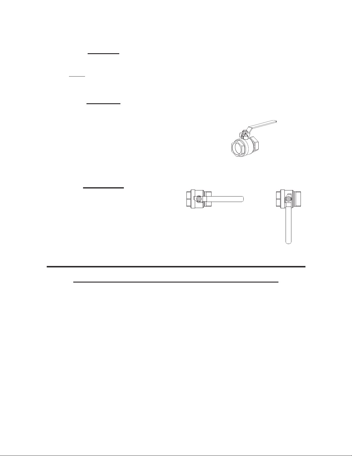
1.2 EMERGENCY SHUTDOWN
If overheating occurs or the gas supply fails to
shut off, close the manual gas shutoff valve
(Figure 1-1) located external to the unit.
IMPORTANT
The Installer must identify and
indicate the location of the emergency
shutdown manual gas valve to
operating personnel.
1.3 PROLONGED SHUTDOWN
After prolonged shutdown, it is recommended
that the startup procedures in Chapter 4 and the
safety device test procedures in Chapter 6 of
this manual be performed, to verify all systemoperating parameters. If there is an emergency,
turn off the electrical power supply to the
AERCO boiler and close the manual gas valve
located upstream the unit. The installer must
identify the emergency shut-off device.
MANUAL GAS SHUTOFF VALVE
VALVE OPEN
VALVE CLOSED
Figure 1-1. Manual Gas Shutoff Valve
IMPORTANT – FOR MASSACHUSETTS INSTALLATIONS ONLY
Boiler Installations within the Commonwealth of Massachusetts must conform to the following
requirements:
x Boiler must be installed by a plumber or a gas fitter who is licensed within the Commonwealth of
Massachusetts.
x Prior to unit operation, the complete gas train and all connections must be leak tested using a
non-corrosive soap.
x If a glycol solution is used as anti-freeze protection, a backflow preventer must be installed
upstream of the Fill/Makeup Valve.
x The vent termination must be located a minimum of 4 feet above grade level.
x If side-wall venting is used, the installation must conform to the following requirements extracted
from 248 CMR 5.08 (2):
(a) For all side wall horizontally vented gas fueled equipment installed in every dwelling, building or
structure used in whole or in part for residential purposes, including those owned or operated by the
Commonwealth and where the side wall exhaust vent termination is less than seven (7) feet above
finished grade in the area of the venting, including but not limited to decks and porches, the following
requirements shall be satisfied:
1-2

SAFETY PRECAUTIONS
1. INSTALLATION OF CARBON MONOXIDE DETECTORS
side wall horizontal vented gas fueled equipment, the installing plumber or gasfitter shall observe
that a hard wired carbon monoxide detector with an alarm and battery back-up is installed on the
floor level where the gas equipment is to be installed. In addition, the installing plumber or
gasfitter shall observe that a battery operated or hard wired carbon monoxide detector with an
alarm is installed on each additional level of the dwelling, building or structure served by the side
wall horizontal vented gas fueled equipment. It shall be the responsibility of the property owner to
secure the services of qualified licensed professionals for the installation of hard wired carbon
monoxide detectors.
Extracted Information From 248 CMR 5.08 (2) – Continued
a. In the event that the side wall horizontally vented gas fueled equipment is installed in
a crawl space or an attic, the hard wired carbon monoxide detector with alarm and
battery back-up may be installed on the next adjacent floor level.
b. In the event that the requirements of this subdivision can not be met at the time of
completion of installation, the owner shall have a period of thirty (30) days to comply with
the above requirements; provided, however, that during said thirty (30) day period, a
battery operated carbon monoxide detector with an alarm shall be installed.
2. APPROVED CARBON MONOXIDE DETECTORS.
required in accordance with the above provisions shall comply with NFPA 720 and be ANSI/UL
2034 listed and IAS certified.
Each carbon monoxide detector as
. At the time of installation of the
3. SIGNAGE
of the building at a minimum height of eight (8) feet above grade directly in line with the exhaust
vent terminal for the horizontally vented gas fueled heating appliance or equipment. The sign
shall read, in print size no less than one-half (1/2) inch in size, "GAS VENT DIRECTLY BELOW.
KEEP CLEAR OF ALL OBSTRUCTIONS".
4. INSPECTION
equipment shall not approve the installation unless, upon inspection, the inspector observes
carbon monoxide detectors and signage installed in accordance with the provisions of 248 CMR
5.08(2)(a)1 through 4.
(b) EXEMPTIONS
1. The equipment listed in Chapter 10 entitled "Equipment Not Required To Be Vented" in the
most current edition of NFPA 54 as adopted by the Board; and
2. Product Approved side wall horizontally vented gas fueled equipment installed in a room or
structure separate from the dwelling, building or structure used in whole or in part for residential
purposes.
(c) MANUFACTURER REQUIREMENTS - GAS EQUIPMENT VENTING SYSTEM PROVIDED.
the manufacturer of Product Approved side wall horizontally vented gas equipment provides a venting
system design or venting system components with the equipment, the instructions provided by the
manufacturer for installation of the equipment and the venting system shall include:
. A metal or plastic identification plate shall be permanently mounted to the exterior
. The state or local gas inspector of the side wall horizontally vented gas fueled
: The following equipment is exempt from 248 CMR 5.08(2)(a)1 through 4:
When
1. Detailed instructions for the installation of the venting system design or the venting system
components; and
2. A complete parts list for the venting system design or venting system.
1-3

SAFETY PRECAUTIONS
(d) MANUFACTURER REQUIREMENTS - GAS EQUIPMENT VENTING SYSTEM NOT PROVIDED.
When the manufacturer of a Product Approved side wall horizontally vented gas fueled equipment does
not provide the parts for venting the flue gases, but identifies "special venting systems", the following
requirements shall be satisfied by the manufacturer:
1. The identification of each "special venting system" shall include the listing of either the
website, phone number or manufacturer’s address where the venting system installation
instructions can be obtained, and
2. The "special venting systems" shall be Product Approved by the Board, and the instructions
for that system shall include a parts list and detailed installation instructions.
(e) A copy of all installation instructions for the Product Approved side wall horizontally vented gas fueled
equipment and all the venting instructions, parts lists and/or design instructions for the venting system
shall remain with the appliance or equipment at the completion of the installation.
_______________________________ [End of Extracted Information From 248 CMR 5.08 (2)]
1-4

INSTALLATION
CHAPTER 2 INSTALLATION
2.1 INTRODUCTION
This Chapter provides the descriptions and
procedures necessary to unpack, inspect and
install the AERCO Benchmark 3.0 Boiler. Brief
descriptions are also provided for each available
mode of operation. Detailed procedures for
implementing these modes are provided in
Chapter 5.
2.2 RECEIVING THE UNIT
Each Benchmark 3.0 System is shipped as a
single crated unit. The shipping weight is
approximately 2,170 pounds. The unit must be
moved with the proper rigging equipment for
safety and to avoid equipment damage. The unit
should be completely inspected for evidence of
shipping damage and shipment completeness at
the time of receipt from the carrier and before
the bill of lading is signed.
NOTE
AERCO is not responsible for lost or
damaged freight.
Each unit has a Tip-N-Tell indicator on the
outside of the crate. This indicates if the unit has
been turned on its side during shipment. If the
Tip-N-Tell indicator is tripped, do not sign for the
shipment. Note the information on the carrier’s
paperwork and request a freight claim and
inspection by a claims adjuster before
proceeding. Any other visual damage to the
packaging materials should also be made clear
to the delivering carrier.
2.3 UNPACKING
Carefully unpack the unit taking care not to
damage the unit enclosure when cutting away
packaging materials
A close inspection of the unit should be made to
ensure that there is no evidence of damage not
indicated by the Tip-N-Tell indicator. The freight
carrier should be notified immediately if any
damage is detected.
The following accessories come standard with
each unit and are either packed separately
within the unit’s packing container or are factory
installed on the boiler:
• Pressure/Temperature Gauge
• Spare Ignitor-Injector
• Spare Flame Detector
• ASME Pressure Relief Valve
• Condensate Drain Trap & Adapter `
• 2” Gas Supply Shutoff Valve
When ordered, optional accessories may be
packed separately, packed within the boiler
shipping container, or may be installed on the
boiler. Any standard or optional accessories
shipped loose should be identified and stored in
a safe place until ready for installation or use.
2.4 SITE PREPARATION.
Ensure that the site selected for installation of
the Benchmark 3.0 Boiler includes:
• Access to AC Input Power corresponding to
the ordered power configuration. The
available power configurations are:
• 208 VAC, 3-Phase, 60 Hz @ 20 A
• 460 VAC, 3-Phase, 60 Hz @ 15 A
• Access to Natural Gas line at a minimum
static pressure of 3.5” W.C.(FM) or 4.0” W.C.
(IRI). Maximum static pressure must not
exceed 2 psi.
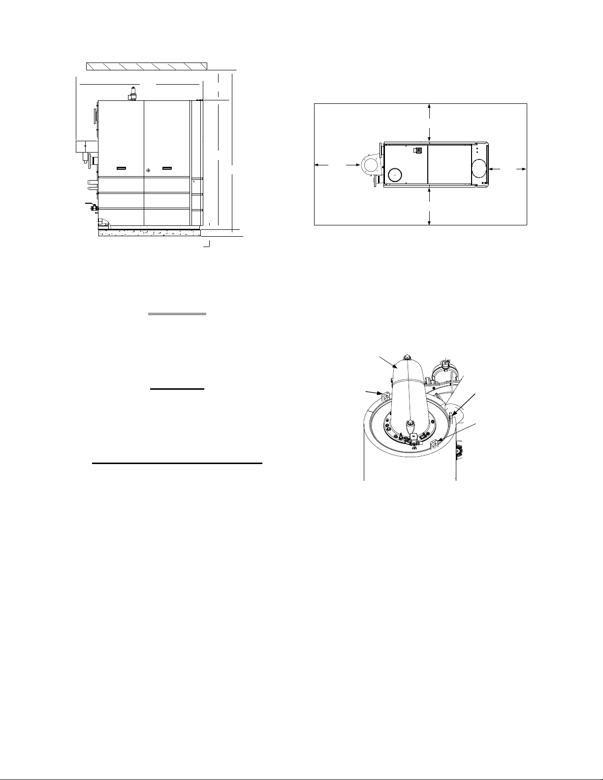
2.4.1 Installation Clearances
The unit must be installed with the prescribed
clearances for service as shown in Figure 2-1.
The minimum
AERCO, are listed below. However, if Local
Building Codes require additional clearances,
these codes shall supersede AERCO’s
requirements. Minimum acceptable clearances
required are:
• Sides: 24 inches
• Front : 24 inches
• Rear: 43 inches
• Top: 18 inches
All gas piping, water piping and electrical conduit
or cable must be arranged so that they do not
interfere with the removal of any panels, or
inhibit service or maintenance of the unit.
clearance dimensions, required by
2-1
INSTALLATION
43"
24"
24"
24"
4" HIGH PAD
REAR
FRONT
77"
18"
101"
79"
PRIMARY HEAT
EXCHANGER
LIFTING
TAB 2
LIFTING
TAB 1
BURNER
ASSEMBLY
LIFTING
TAB 3
Figure 2-1 Benchmark 3.0 Boiler Clearances
WARNING
KEEP THE UNIT AREA CLEAR AND
FREE FROM ALL COMBUSTIBLE
MATERIALS AND FLAMMABLE
VAPORS OR LIQUIDS
.
Remove the four (4) lag screws securing the unit
to the shipping skid. Lift the unit off the shipping
skid and position it on the 4 inch to 6 inch
housekeeping concrete pad (required) in the
desired location.
CAUTION
While packaged in the shipping
container, the boiler must be moved
by pallet jack or forklift from the
FRONT ONLY.
FOR MASSACHUSETTS ONLY
For Massachusetts installations, the
boiler must be installed by a plumber
or gas fitter who is licensed within the
Commonwealth of Massachusetts. In
addition, the installation must comply
with all requirements specified in
Chapter 1 (Safety Precautions), pages
1-2 & 1-3.
2.4.2 Setting the Unit
The unit must be installed on a 4 inch to 6 inch
housekeeping pad to ensure proper condensate
drainage. If anchoring the unit, refer to the
dimensional drawings in Appendix F for anchor
locations. A total of 3 lifting tabs are provided at
the top of the primary heat exchanger as shown
in Figure 2-2. However, USE ONLY TABS 1
AND 2 SHOWN IN FIGURE 2-2 TO MOVE THE
ENTIRE UNIT. Tabs 1 and 3 are used only
when removing or replacing the unit’s primary
heat exchanger. Remove the front top panel
from the unit to provide access to the lifting tabs.
2-2
Figure 2-2
Lifting Lug Locations
In multiple unit installations, it is important to
plan the position of each unit in advance.
Sufficient space for piping connections and
future service/maintenance requirements must
also be taken into consideration. All piping must
include ample provisions for expansion.
If installing a Combination Control Panel (CCP)
system, it is important to identify the
Combination Mode Boilers in advance and place
them in the proper physical location. Refer to
Chapter 5 for information on Combination Mode
Boilers.
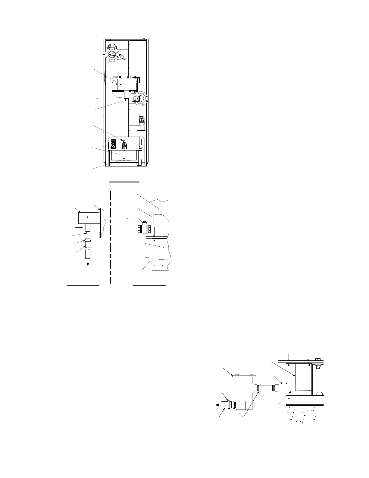
2.4.3 Removal of Support Rod
Prior to installation of water supply and return
piping, the 24” threaded rod shown in Figure 2-3
must be removed. This rod is installed prior to
shipment from the factory to prevent damage to
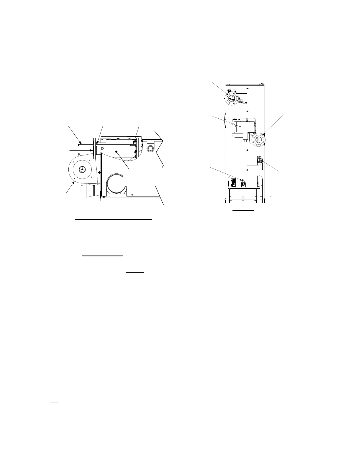
INSTALLATION
5/8-11 x 24" LONG
THREADED ROD
5/8-11
HEX NUT
5/8-11
COUPLING NUT
EXHAUST
MANIFOLD
OUTLET
FLANGE
INSULATED
FLEX HOSE
(SEE IMPORTANT
NOTE BELOW)
PARTIAL TOP VIEW - REAR
BOILER SUPPLY
4" – 150# FLANGED
CONNECTION
BOILER RETURN
4" – 150# FLANGED
CONNECTION
2" GAS INLET
CONNECTION
SHELL DRAIN
VALVE
EXHAUST
MANIFOLD
REAR VIEW
the insulated metal flex hose on the hot water
supply outlet of the boiler. In order to install the
water supply piping, this rod must be removed
as follows:
1. Refer to Figure 2-3 and back off the hex nut
on the outlet side of the flex hose.
2. Next, disconnect the coupling nut from the
flange stud.
3. Completely remove the threaded rod, hex
nut and coupling nut from the boiler.
piping connections. The physical location of the
supply and return piping connections are on the
rear of the unit as shown in Figure 2-4. Refer to
Appendix F, Drawing AP-A-811 for additional
dimensional data.
Figure 2-3
Location of Threaded Support Rod
IMPORTANT
THE INSULATED FLEX HOSE
SHOWN IN FIGURE 2-3 MUST
LEVEL OR SLOPING UPWARD AS
IT EXITS THE BOILER. FAILURE TO
PROPERLY POSITION THIS HOSE
MAY CAUSE INEFFECTIVE AIR
ELIMINATION RESULTING IN ELEVATED TEMPERATURES THAT
COULD COMPROMISE THE TOP
HEAD GASKET.
2.4.4 Removal of Strap and Packing
Material From Heat Exchanger
Prior to connecting the external gas supply or
electrical power to the unit. the strap and
packing material must be removed from the top
of the primary heat exchanger. This material is
located in the area of the ignitor-injector and
staged ignition solenoid on the burner assembly
This can be easily accomplished by removing
the top
panel nearest to the front of the unit.
2.5 SUPPLY AND RETURN PIPING
The Benchmark 3.0 Boiler utilizes 4” 150#
flanges for the water system supply and return
BE
Figure 2-4
Supply and Return Locations
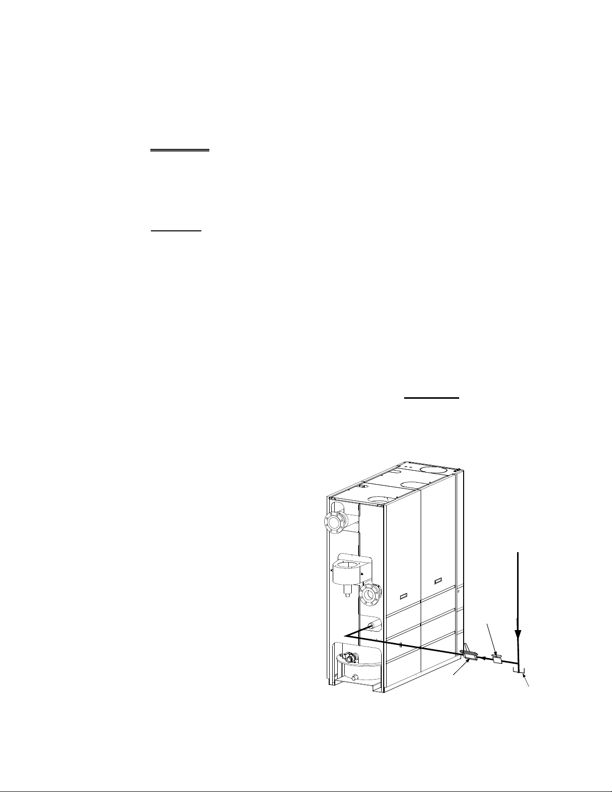
2.6 CONDENSATE DRAINS
The Benchmark 3.0 Boiler is designed to
condense water vapor from the flue products.
Therefore, the installation must have provisions
for suitable condensate drainage or collection.
Two condensate drain connections are provided
on the rear of the unit as shown in Figure 2-5.
One drain connection is located on the exhaust
manifold and the other is located on the
connecting manifold.
The drain at the bottom of the exhaust manifold
also includes a condensate trap containing a
float assembly. When condensate collects in the
exhaust manifold, the float rises, thereby
allowing it to discharge through the drain
opening. The drain pipe located on the
connecting manifold must be connected to a
second condensate trap which is packed
separately within the unit’s shipping container.
The procedures to install and connect both of
the condensate drains are provided in
paragraphs 2.6.1 and 2.6.2.
2-3
INSTALLATION
SHELL DRAIN
VALVE
EXHAUST
MANIFOLD
REAR VIEW
A
A
B
B
CONDENSATE
TRAP
DRAIN
CONNECTING
MANIFOLD
DRAIN
UNIT
FRAME
CONNECTING
MANIFOLD
DRAIN
VALVE
CONDENSATE
DRAIN PIPE
TO
CONDENSATE
TRAP
SHELL
VIEW “B - B”
VIEW “A - A”
UNIT
FRAME
EXHAUST
MANIFOLD
CONDENSATE
TRAP
DRAIN
HOSE
CLAMP
1" I.D.
HOSE
TO FLOOR
DRAIN
CONDENSATE
TRAP
CONNECTING
MANIFOLD
DRAIN
PIPE
3/4" NPT
NIPPLES
TO
FLOOR
DRAIN
CLAMP
1" I.D.
HOSE
ADAPTOR
and a 3/4” NPT x 5” long nipple. Refer to Figure
2-6 and install the trap as follows:
NOTE
The condensate trap described in the
following steps can be installed on the
floor behind the unit as shown in Figure 2-
6. Ensure that the condensate trap inlet is
level with or below the connecting
manifold drain pipe. Ensure that the outlet
hose from the trap slopes away (down)
from the trap.
1. Apply Teflon tape to the threads of the 3/4” x
5” long nipple provided with the boiler.
2. Attach the 3/4” NPT nipple between the
condensate trap inlet and the trap adaptor
(Figure 2-6).
3. Attach another 3/4” NPT nipple (not supplied) to the condensate trap outlet on the
lower part of the trap.
4. Connect the condensate trap and adaptor to
the connecting manifold drain pipe. Position
the trap so it is level and then tighten the
thumb screw on the adaptor.
Figure 2-5
Condensate Drain Connection Location
2.6.1 Exhaust Manifold Condensate
Drain
Refer to Figure 2-5, View A – A and install as
follows:
1. Connect a length of 1 inch I.D. hose (part no.
91030) to the drain on the exhaust manifold
and secure it in place with a hose clamp.
2. Route the hose to a nearby floor drain.
2.6.2 Connecting Manifold Condensate
Drain
The connecting manifold drain pipe shown in
Figure 2-5, View B – B must be connected to a
separate condensate drain trap external to the
unit. This condensate trap (part no. 24060) is
supplied with the unit along with a trap adapter
2-4
5. Place a suitable support under the
condensate trap to maintain the trap in the
level position.
6. Connect a length of 1” I.D. polypropylene hose
to the outlet side of the condensate trap and
route it to a nearby floor drain.
If desired, a Tee fitting may be used to connect the
two drain hoses from the exhaust manifold and the
outlet side
of the of the condensate trap attached to
the connecting manifold.
If a floor drain is not available, a condensate pump
can be used to remove the condensate to drain.
The maximum condensate flow rate is 20 GPH.
The condensate drain trap, associated fittings and
drain lines must be removable for routine
maintenance.
Figure 2-6
Condensate Trap Installation
INSTALLATION
NATURAL
GAS
SUPPLY
DIRT
TRAP
2" MANUAL
SHUTOFF
VALVE
MANDATORY
REGULATOR FOR
MASSACHUSSETTS
INSTALLATIONS ONLY
2.7 GAS SUPPLY PIPING
The AERCO Benchmark 3.0 Gas Components
and Supply Design Guide, GF-3030 must be
consulted prior to designing or installing any gas
supply piping.
WARNING
NEVER USE MATCHES, CANDLES,
FLAMES OR OTHER SOURCES OF
IGNITION TO CHECK FOR GAS
LEAKS
Many soaps used for gas pipe leak
testing are corrosive to metals. Therefore, piping must be rinsed thoroughly
with clean water after leak checks
have been completed.
All gas piping must be arranged so that it
does not interfere with removal of any
covers, inhibit service/maintenance, or
restrict access between the unit and
walls, or another unit.
.
CAUTION
NOTE
2.7.2 Manual Gas Shutoff Valve
A manual shut-off valve must be installed in the
gas supply line upstream of the Boiler as shown
in Figure 2-7. Maximum allowable gas pressure
to the Boiler is 2 psi
NOTE
Paragraph 2.7.3 applies only to bolier
installations within the Commonwealth of
Massachusetts.
2.7.3 External Gas Supply Regulator
For Massachusetts installations, a mandatory
external gas supply regulator must be positioned
as shown in Figure 2-7. The gas supply
regulator must be properly vented to outdoors.
Consult the local gas utility for detailed
requirements concerning venting of the the
supply gas regulator.
NOTE
The external regulator must be capable of
regulating 3,00,000 BTU/HR of natural
gas while maintaining a gas pressure to
the boiler of 3.5” W.C. for FM or 4.0” W.C.
for IRI gas trains.
A 2 inch gas inlet connection is located on the
rear of the unit as shown in Figure 2-4.
Prior to installation, all pipes should be deburred and internally cleared of any scale, metal
chips or other foreign particles. Do Not install
any flexible connectors or unapproved gas
fittings. Piping must be supported from the floor,
ceiling or walls only and must not be supported
by the unit.
A suitable piping compound, approved for use
with natural gas, should be used. Any excess
must be wiped off to prevent clogging of
components.
To avoid unit damage when pressure testing gas
piping, isolate the unit from the gas supply
piping. At no time should the gas pressure
applied to the unit exceed 2 psi. Leak test all
external piping thoroughly using a soap and
water solution or suitable equivalent. The gas
piping used must meet all applicable codes.
2.7.1 Gas Supply Specification
The gas supply input specifications to the unit
for Natural Gas are as follows:
CAUTION
A lock-up style regulator MUST be
used when gas supply pressure will
exceed 14” W.C.
The maximum static pressure to the unit must
not exceed 2 psi. The gas supply pressure to the
unit must be of sufficient capacity to provide
3000 cfh while maintaining the gas pressure at
3.5” W.C. for FM or 4.0” for IRI gas trains.
Figure 2-7
Manual Gas Shut-Off Valve Location
2-5
INSTALLATION
UPPER RIGHT CORNER OF FRONT PANEL
TERMINAL BLOCK
GND
NEU
L2
L3
L1
208 VAC, 3 PHASE
208 VAC, 3 Phase
GND
L2
L3
L1
460 VAC, 3 PHASE
460 VAC, 3 Phase
2.7.4 IRI Gas Train Kit
The IRI gas train is an optional gas train
configuration which is required in some areas for
code compliance or for insurance purposes.
The IRI gas train is factory pre-piped and wired.
See Appendix F, Drawing AP-A-803 for details.
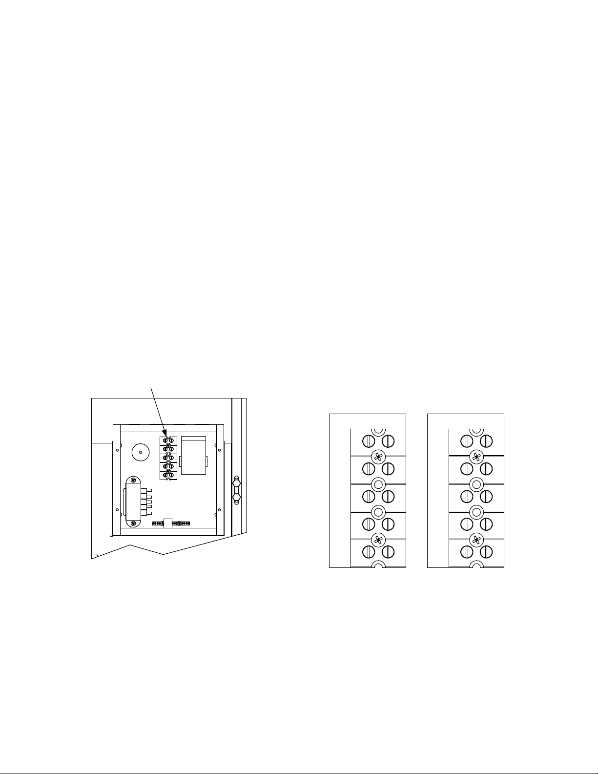
2.8 AC ELECTRICAL POWER WIRING
The AERCO Benchmark 3.0 Electrical Power
Wiring Guide, GF-3060, must be consulted prior
to connecting any AC power wiring to the unit.
External AC power connections are made to the
unit inside the Power Box on the front panel of
the unit. Remove the front door of the unit to
access the Power Box mounted directly above
the Control Box. Loosen the four Power Box
cover screws and remove cover to access the
AC terminal connections inside the Power Box
(Figure 2-8).
NOTE
All electrical conduit and hardware must
be installed so that it does not interfere
with the removal of any unit covers, inhibit
service/maintenance, or prevent access
between the unit and walls or another
unit.
configuration ordered. The two different terminal
block configurations are shown in Figure 2-9. A
wiring diagram showing the required AC power
connections is provided on the front cover of the
Power Box.
Each Benchmark 3.0 Boiler must be connected
to a dedicated electrical circuit. NO OTHER
DEVICES SHOULD BE ON THE SAME
ELECTRICAL CIRCUIT AS THE BENCHMARK
BOILER.
A double-pole switch must be installed on the
electrical supply line in an easily accessible
location to quickly and safely disconnect
electrical service. DO NOT attach the switch to
sheet metal enclosures of the unit.
After placing the boiler in service, the ignition
safety shutoff device must be tested. If an
external electrical power source is used, the
installed boiler must be electrically bonded to
ground in accordance with the requirements of
the authority having jurisdiction. In the absence
of such requirements, the installation shall
conform to National Electrical Code (NEC),
ANSI/NFPA 70 and/or the Canadian Electrical
Code (CEC) Part I, CSA C22.1 Electrical Code.
For electrical power wiring diagrams, see the
AERCO Benchmark 3.0 Electrical Power Wiring
Guide, (GF-3060).
Figure 2-8
AC Input Terminal Block Location
2.8.1 Electrical Power Requirements
The AERCO Benchmark 3.0 Boiler is available
in two different AC power configurations:
• 208 VAC/3-Phase/60 @20 amps
• 460 VAC/3-Phase/60 Hz @ 15 amps
Each of the power configurations utilize a Power
Box with a terminal block that matches the
2-6
Figure 2-9
AC Terminal Block Configurations
2.9 MODES OF OPERATION AND FIELD
CONTROL WIRING
The Benchmark 3.0 Boiler is available in several
different modes of operation. While each unit is
factory configured and wired for its intended
mode, some additional field wiring may be
required to complete the installation. This wiring
is typically connected to the Input/Output (I/O)
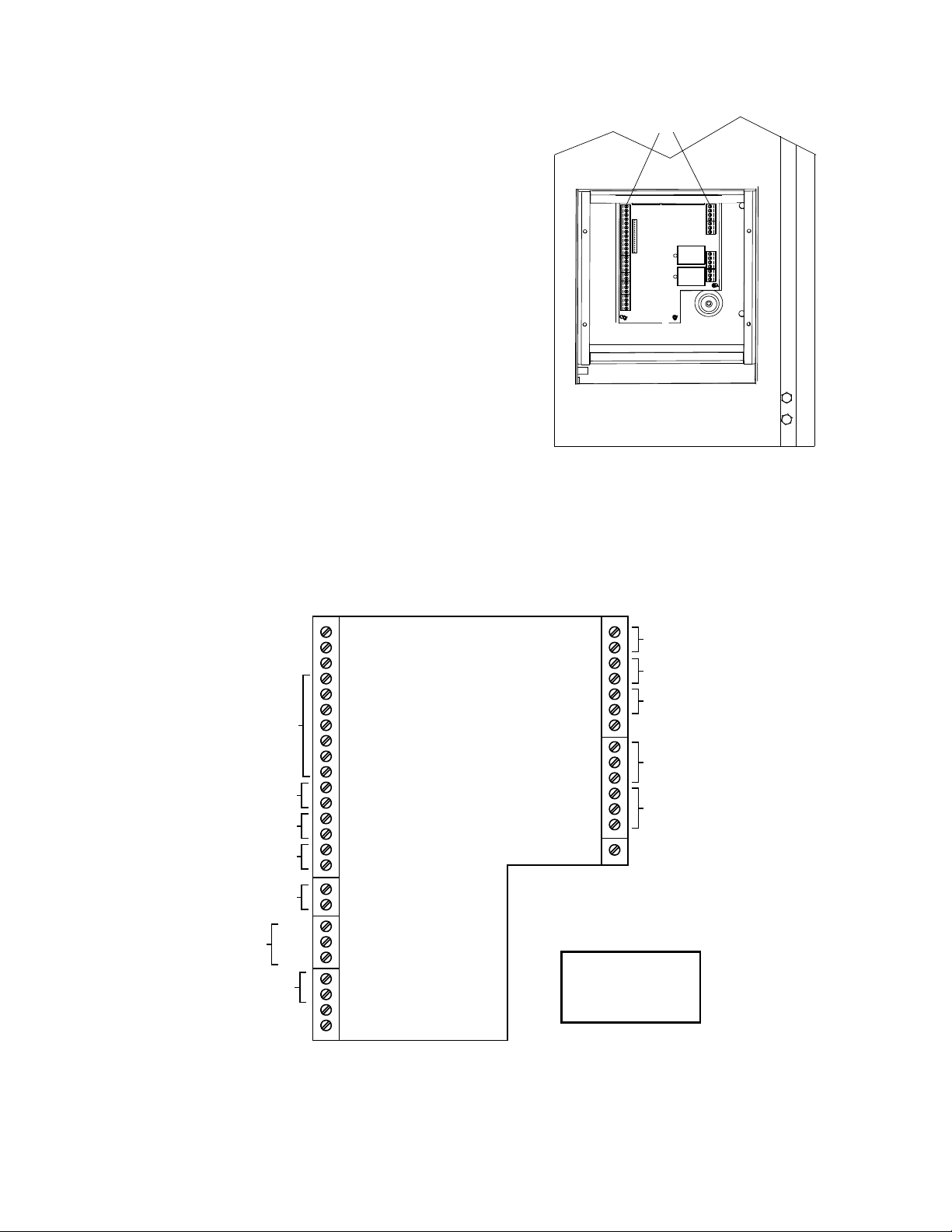
Box located on the lower portion of the unit front
TERMINAL
STRIPS
LOWER RIGHT CORNER
OF FRONT PANEL
mA OUT
RS-485
COMM.
+
-
+
-
ANALOG IN
SENSOR COMMON
OUTDOOR SENSOR IN
REMOTE INTL'K IN
B.M.S. (PWM) IN
SHIELD
+
-
+
-
(AIR) AUX SENSOR IN
NOT USED
EXHAUST SWITCH IN
DELAYED INTL'K IN
FAULT RELAY
120 VAC, 5A, RES
AUX RELAY
120 VAC, 5A, RES
G
RELAY CONTACTS:
120 VAC, 30 VDC
5 AMPS RESISTIVE
DANGER
120 VAC USED
IN THIS BOX
NOT USED
NOT USED
NC
COM
NO
NC
COM
NO
NOT USED
0 – 10V
AGND
panel (Figure 2-10) behind the removable front
door.
To access the I/O Box terminal strips shown in
Figure 2-10, loosen the four cover screws and
remove the cover. All field wiring is installed
from the rear of the panel by routing the wires
through one of the four bushings provided.
Refer to the wiring diagram provided on the
cover of the I/O Box (Figure 2-11) when making
all wiring connections.
Brief descriptions of each mode of operation,
and their wiring requirements, are provided in
the following paragraphs. Additional information
concerning field wiring is provided in paragraphs
2.9.1 through 2.9.9. Refer to Chapter 5 for
detailed information on the available modes of
operation
INSTALLATION
Figure 2-10.
Input/Output (I/O) Box Location
Figure 2-11. I/O Box Terminal Strip
2-7

INSTALLATION
2.9.1 Constant Setpoint Mode
The Constant Setpoint Mode is used when it is
desired to have a fixed setpoint that does not
deviate. No wiring connections, other than AC
electrical power connections, are required for
this mode. However, if desired, fault monitoring
or enable/disable interlock wiring can be utilized
(see paragraphs 2.9.9.1 and 2.9.10).
2.9.2 Indoor/Outdoor Reset Mode
This mode of operation increases supply water
temperature as outdoor temperatures decrease.
An outside air temperature sensor (AERCO Part
No. 122790) is required. The sensor MUST BE
wired to the I/O Box wiring terminals (see Figure
2-11). Refer to paragraph 2.10.1 for additional
information on outside air temperature sensor
installation.
2.9.3 Boiler Management System Mode
NOTE
BMS Model 168 can utilize either pulse
width modulation (PWM) or RS485
Modbus signaling to the Boiler. BMS II
Model 5R5-384 can utilize only RS485
signaling to the Boiler.
When using an AERCO Boiler Management
System (BMS), the field wiring is connected
between the BMS Panel and each Boiler’s I/O
Box terminal strip (Figure 2-11). Twisted
shielded pair wire from 18 to 22 AWG must be
utilized for the connections. The BMS Mode can
utilize either pulse width modulation (PWM)
signaling, or RS485 Modbus signaling. For PWM
signaling, connections are made from the
AERCO Boiler Management System to the
B.M.S. (PWM) IN terminals on the I/O Box
terminal strip. For RS485 Modus signaling,
connections are made from the BMS to the
RS485 COMM terminals on the I/O Box terminal
strip. Polarity must be maintained and the shield
must be connected only at the AERCO BMS.
The boiler end of the shield must be left floating.
For additional instructions, refer to Chapter 5,
paragraph 5.6 in this manual. Also, refer to GF108M (BMS Model 168) and GF-124 (BMS II
Model 5R5-384), BMS -Operations Guides.
2.9.4 Remote Setpoint and Direct Drive
Modes
The Benchmark 3.0 Boiler can accept several
types of signal formats from an Energy
Management System (EMS), Building
Automation System (BAS) or other source, to
control either the setpoint (Remote Setpoint
Mode) or firing rate (Direct Drive Mode) of the
Boiler. These formats are:
2-8
• 4 to 20 mA/1 to 5 VDC
• 0 to 20 mA/0 to 5 VDC
• PWM – (Pulse Width Modulated signal. See
para. 2.10.4)
• Network (RS485 Modbus. See para. 2.10.8)
While it is possible to control a boiler or boilers
using one of the previously described modes of
operation, it may not be the method best suited
for the application. Prior to selecting one of
these modes of operation, it is recommended
that you consult with your local AERCO
representative or the factory for the mode of
operation that will work best with your
application. For more information on wiring the
4 to 20 mA / 1to 5VDC or the 0 to 20 mA / 0 to 5
VDC, see paragraph 2.9.3.
2.9.5 Combination Mode
NOTE
Only BMS Model 168 can be utilized for
the Combination Mode, not the BMS II
(Model 5R5-384).
With a Combination Mode unit, field wiring is
between the unit’s I/O Box wiring terminals, the
CCP (Combination Control Panel), and the BMS
Model 168 (Boiler Management System). The
wiring must be accomplished using twistedshielded pair wire from 18 to 22 AWG. Polarity
must be maintained. For further instructions and
wiring diagrams, refer to the GF-108 Boiler
Management System Operations Guide and the
CCP-1 data sheet.
2.10 I/O BOX CONNECTIONS
The types of input and output signals and
devices to be connected to the I/O Box terminals
shown in Figure 2-11 are described in the
following paragraphs.
CAUTION
DO NOT make any connections to the
I/O Box terminals labeled “NOT
USED”. Attempting to do so may
cause equipment damage.
2.10.1 OUTDOOR SENSOR IN
An outdoor air temperature sensor (AERCO Part
No. 122790) will be required primarily for the
Indoor/Outdoor reset mode of operation. It can
also be used with another mode if it is desired to
use the outdoor sensor enable/disable feature.
This feature allows the boiler to be enabled or
disabled based on the outdoor air temperature.
The factory default for the outdoor sensor is
DISABLED. To enable the sensor and/or select

INSTALLATION
an enable/disable outdoor temperature, see the
Configuration menu in Chapter 3.
The outdoor sensor may be wired up to 200 feet
from the boiler. It is connected to the OUTDOOR
SENSOR IN and SENSOR COMMON terminals
in the I/O Box (see Figures 2-10 and 2-11). Wire
the sensor using a twisted shielded pair wire
from 18 to 22 AWG. There is no polarity to
observe when terminating these wires. The
shield is to be connected only to the terminals
labeled SHIELD in the I/O Box. The sensor end
of the shield must be left free and ungrounded.
When mounting the sensor, it must be located
on the North side of the building where an
average outside air temperature is expected.
The sensor must be shielded from direct sunlight
as well as impingement by the elements. If a
shield is used, it must allow for free air
circulation.
2.10.2 AIR SENSOR IN
The AIR SENSOR IN is connected to the AUX
SENSOR IN and SENSOR COMMON terminals
on the I/O board. The AIR SENSOR measures
the temperature of the air input to the Air/Fuel
Valve. This temperature reading is one of the
components used to calculate the rotational
speed of the blower used in the combustion
Calibration process (Chapter 4).
The AUX SENSOR IN terminals can be used to
add an additional temperature sensor for
monitoring purposes. This input is always
enabled and is a view-only input that can be
seen in the Operating Menu. The sensor must
be wired to the AUX SENSOR IN and SENSOR
COMMON terminals and must be similar to
AERCO BALCO wire sensor Part No. 12449. A
resistance chart for this sensor is provided in
Appendix C.
2.10.3 ANALOG IN
The ANALOG IN + and – terminals are used
when an external signal is used to drive the
firing rate (Direct Drive Mode) or change the
setpoint (Remote Setpoint Mode) of the Boiler.
Either a 4 to 20 mA /1 to 5 VDC or a 0 to 20 mA
/ 0 to 5 VDC signal may be used to vary the
setpoint or firing rate. The factory default setting
is for 4 to 20 mA / 1 to 5 VDC, however this may
be changed to 0 to 20 mA / 0 to 5 VDC using the
Configuration Menu described in Chapter 3. If
voltage rather than current is selected as the
drive signal, a DIP switch must be set on the
PMC Board located inside the Control Box.
Contact the AERCO factory for information on
setting DIP switches.
All of the supplied signals must be floating
(ungrounded) signals. Connections between the
signal source and the Boiler’s I/O Box must be
made using twisted shielded pair wire from 18 to
22 AWG, such as Belden 9841 (see
Figure 2-11). Polarity must be maintained. The
shield must be connected only at the source end
and must be left floating (not connected) at the
Boiler’s I/O Box.
Regardless of whether voltage or current is used
for the drive signal, they are linearly mapped to
a 40°F to 240°F setpoint or a 0% to 100% firing
rate. No scaling for these signals is provided
2.10.4 B.M.S. (PWM) IN
NOTE
Only BMS Model 168 can utilize Pulse
Width Modulation (PWM), not the BMS II
(Model 5R5-384).
These terminals are used to connect the
AERCO Boiler Management System (BMS)
Model 168 to the unit. The BMS Model 168
utilizes a 12 millisecond, ON/OFF duty cycle.
This duty cycle is Pulse Width Modulated (PWM)
to control firing rate. A 0% firing rate = a 5% ON
pulse and a 100% firing rate = a 95% ON pulse.
2.10.5 SHIELD
The SHIELD terminals are used to terminate any
shields used on sensor wires connected to the
unit. Only shields must be connected to these
terminals.
IMPORTANT
DO NOT USE the mA OUT output to
remotely monitor Setpoint, Outlet Temp or
Fire Rate Out.
2.10.6 mA OUT
These terminals provide a 4 to 20 mA output to
the VFD (if so equipped) to control the rotational
speed of the blower. This function is enabled in
the Configuration Menu (Chapter 3, Table 3-4).
2.10.7 0 – 10V OUT
These terminals provide a 0 to 10V output to
control the rotational speed of the blower. This
function is enabled in the Configuration Menu
(Chapter 3, Table 3-4).
2.10.8 RS-485 COMM
These terminals are used for RS-485 MODBUS
serial communication between the unit and an
external “Master” such as a Boiler Management
System (BMS), Energy Management System
(EMS), Building Automation System (BAS) or
other suitable device.
2-9
INSTALLATION
2.10.9 EXHAUST SWITCH IN
These terminals permit an external exhaust
switch to be connected to the exhaust manifold
of the boiler. The exhaust switch should be a
normally open type switch (such as AERCO Part
No. 123463) that closes (trips) at 500°F.
2.10.10 INTERLOCKS
The unit offers two interlock circuits for
interfacing with Energy Management Systems
and auxiliary equipment such as pumps or
louvers. These interlocks are called the Remote
Interlock and Delayed Interlock (Figure 2-11).
The wiring terminals for these interlocks are
located inside the I/O Box on the unit front
panel. The I/O Box cover contains a wiring
diagram which shows the terminal strip locations
for these interlocks (REMOTE INTL’K IN and
DELAYED INTL’K IN). Both interlocks,
described below, are factory wired in the closed
position.
IMPORTANT
Both the Remote Interlock and Delayed
Interlock MUST be in the closed position
to allow the unit to fire.
2.10.10.1 REMOTE INTERLOCK IN
The remote interlock circuit is provided to
remotely start (enable) and stop (disable) the
Boiler, if desired. The circuit is labeled
REMOTE INTL’K IN and is located inside the I/O
Box on the front panel. The circuit is 24 VAC
and is factory pre-wired in the closed (jumpered)
position.
2.10.10.2 DELAYED INTERLOCK IN
The delayed interlock is typically used in
conjunction with the auxiliary relay described in
paragraph 2.10. This interlock circuit is located
in the purge section of the start string. It can be
connected to the proving device (end switch,
flow switch etc.) of an auxiliary piece of
equipment started by the Boiler’s auxiliary relay.
The delayed interlock must be closed for the
boiler to fire.
If the delayed interlock is connected to a proving
device that requires time to close (make), a time
delay (Aux Start On Dly) that holds the start
sequence of the boiler long enough for a proving
switch to make can be programmed. Should the
proving switch not prove within the programmed
time frame, the boiler will shut down. The Aux
Start On Dly can be programmed from 0 to 120
seconds. This option is locate in the
Configuration Menu (Chapter 3, Table 3-4).
2.10.11 FAULT RELAY
The fault relay is a single pole double throw
(SPDT) relay having a normally open and
normally closed set of relay contacts that are
rated for 5 amps at 120 VAC and 5 amps at 30
VDC. The relay energizes when any fault
condition occurs and remains energized until the
fault is cleared and the CLEAR button is
depressed. The fault relay connections are
shown in Figure 2-11.
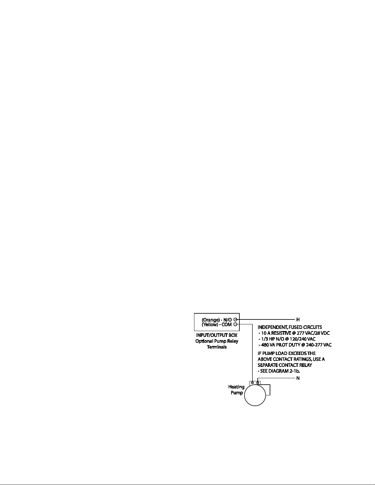
2.10.12 BENCHMARK PUMP RELAY
OPTION
An optional Benchmark pump relay allows the
user to turn a pump on/off and open/close a
motorized valve as the boiler cycles on and off
on demand. The Pump Delay Timer feature
allows the user to keep the pump running and
keep the motorized valve open for up to 30
minutes after the boiler has shut down and the
demand is satisfied.
The Benchmark pump relay (SPDT) contact is
rated for:
• 10 A Resistive @ 277 VAC/28 VDC
• 1/3 HP N/O @ 120/240 VAC
• 1/6 HP N/C @ 120/240 VAC
• 480 VA Pilot Duty @ 240-277 VAC
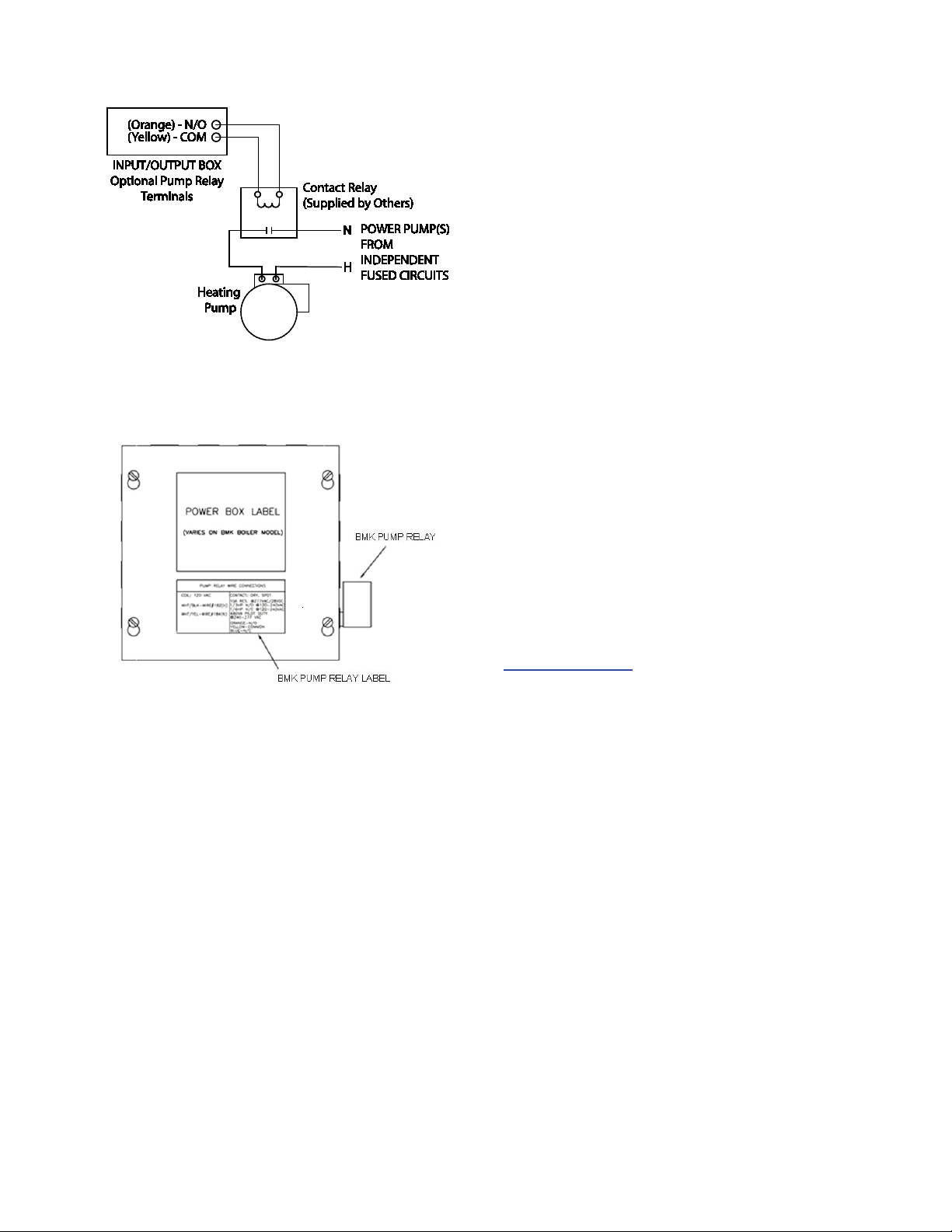
If pump/valve load exceeds the above contact
ratings, use a separate contact relay.
See Diagrams 2-1a and 2-1b.
To identify if the boiler is equipped with the BMK
Pump Relay Option (part no. 69102), look for the
label and relay as shown in Figure 2-12.
Diagram 2-1a: Schematic – System Pump
Start using Boiler Pump Relay
2-10
INSTALLATION
Diagram 2-1b: Schematic – System Pump
Start using a Separate Contact Relay
for safety and code compliance. Since the unit is
capable of discharging low temperature exhaust
gases, horizontal sections of the flue vent
system must be pitched back to the unit a
minimum of 1/4 inch per foot to avoid
condensate pooling and allow for proper
drainage.
The combined pressure drop of vent and
combustion air systems must not exceed 140
equivalent feet of 8 inch ducting. Fittings as well
as pipe lengths must be calculated as part of the
equivalent length.
For a natural draft installation the draft must not
exceed ±0.25 inch W.C. These factors must be
planned into the vent installation. If the
maximum allowable equivalent lengths of piping
are exceeded, the unit will not operate properly
or reliably.
For Massachusetts boiler installations, the
Heatfab Division of the Selkirk Corporation
provides vent systems which conform to all
applicable requirements for installations within
the Commonwealth of Massachusetts. Contact
information for this supplier is as follows:
Figure 2-12: Identifying the Presence of BMK
Pump Relay Option 69102
2.11 AUXILIARY RELAY CONTACTS
Each Boiler is equipped with a single pole
double throw (SPDT) relay that is energized
when there is a demand for heat and deenergized after the demand for heat is satisfied.
The relay is provided for the control of auxiliary
equipment, such as pumps and louvers, or can
be used as a Boiler status indictor (firing or not
firing). Its contacts are rated for 120 VAC @ 5
amps. Refer to Figure 2-11 to locate the AUX
RELAY terminals for wiring connections.
2.12 FLUE GAS VENT INSTALLATION
The minimum allowable vent diameter for a
single Benchmark 3.0 Boiler is 8 inches.
The AERCO Benchmark Venting and
Combustion Air Guide, GF-2050, must be
consulted before any flue gas vent or inlet air
venting is designed or installed. U/L listed,
positive pressure, watertight vent materials as
specified in AERCO’s GF-2050, must be used
Selkirk Corporation
Heatfab Division
130 Industrial Blvd.
Turners Falls, MA 01376
Phone: 1-800-772-0739
www.heat-fab.com
2.13 COMBUSTION AIR
The AERCO Benchmark Venting and Combustion Air Guide, GF-2050 MUST be consulted
before any flue or combustion supply air venting
is designed or implemented. Combustion air
supply is a direct requirement of ANSI 223.1,
NFPA-54, CSA B149.1 and local codes. These
codes should be consulted before a permanent
design is determined.
The combustion air must be free of chlorine,
halogenated hydrocarbons, or other chemicals
that can become hazardous when used in gasfired equipment. Common sources of these
compounds are swimming pools, degreasing
compounds, plastic processing and refrigerants.
Whenever the environment contains these types
of chemicals, combustion air must be supplied
from a clean area outdoors for the protection
and longevity of the equipment.
The AERCO Benchmark 3.0 Boiler is UL listed
for 100% sealed combustion. It can also be
installed using room air, provided there is an
adequate supply. (See paragraph 2.13.3 for
more information concerning sealed combustion
air). If the sealed combustion air option is not
2-11

INSTALLATION
being used, an inlet screen will be attached at
the air inlet on the top of the unit
The more common methods of supplying
combustion air are outlined below. For more
information concerning combustion air, consult
the AERCO Benchmark Venting and
Combustion Air Guide, GF-2050.
2.13.1 Combustion Air From Outside the
Building
Air supplied from outside the building must be
provided through two permanent openings. Each
opening must have a free area of not less than
one square inch for each 4000 BTU/H boiler
input. The free area must take into account
restrictions such as louvers and bird screens.
For Canada installations, refer to the
requirements specified in CSA B149.1-10, 8.4.1
and 8.4.3.
2.13.2 Combustion Air From Inside the
Building
When combustion air is provided from within the
building, it must be supplied through two
permanent openings in an interior wall. Each
opening must have a free area of not less than
one square inch per 1000 BTU/H of total boiler
input. The free area must take into account any
restrictions such as louvers.
2.13.3 Sealed Combustion
The AERCO Benchmark 3.0 Boiler is UL listed
for 100%-sealed combustion. For sealed
combustion installations, the screen on the air
inlet duct of the unit must be removed. The inlet
air ductwork must then be attached directly to
the unit’s air inlet.
In a sealed combustion air application, the
combustion air ducting pressure losses must be
taken into account when calculating the total
maximum allowable venting run. See the
AERCO Benchmark Venting and Combustion
Air Guide, GF-2050. When using the boiler in a
sealed combustion air configuration, each unit
must have a minimum 8-inch diameter
connection at the unit.
2.13.4 Temporary Combustion Air
Filtering During Construction
When the AERCO Benchmark 3.0 Boiler is used
to provide heat temporarily during ongoing
building construction, accumulated drywall dust,
sawdust and similar particles can accumulate in
the unit’s combustion air intake filter and block
combustion air flow. In these situations, AERCO
recommends that a disposable air intake filter be
installed, temporarily, above the boiler
combustion air inlet.
AERCO recommends that the temporary air filter
be cut from a McMaster-Carr part no. 2122K315
Polyester Air Filter Roll Tackfield, 1/2” thick, 16”
wide, or equivalent. Cover the Benchmark 3.0
air inlet with the blue side of the filter material
facing outward to hold the dust on the outside
surface. Maximize the surface area of the filter
covering the 8" diameter opening by creating a
dome out of the filter material.
During construction, check the filter for dust
accumulation and replace it when the
accumulation becomes noticeable.
2-12
CONTROL PANEL OPERATING PROCEDURES
1
2
3
4
5
6
7
8
9
10
11
12
CHAPTER 3 CONTROL PANEL OPERATING PROCEDURES
3.1 INTRODUCTION
The information in this Chapter provides a guide
to the operation of the Benchmark 3.0 Boiler
using the Control Panel mounted on the front of
the unit. It is imperative that the initial startup of
this unit be performed by factory trained
personnel. Operation prior to initial startup by
factory trained personnel will void the equipment
warranty. In addition, the following WARNINGS
and CAUTIONS must be observed at all times.
CAUTION
All of the installation procedures in
Chapter 2 must be completed before
attempting to start the unit.
WARNING
ELECTRICAL VOLTAGES IN THIS
SYSTEM MAY INCLUDE 460, 208
AND 24 VOLTS AC. IT MUST BE
SERVICED ONLY BY FACTORY
CERTIFIED SERVICE TECHNICIANS
WARNING
DO NOT ATTEMPT TO DRY FIRE
THE BOILER. STARTING THE UNIT
WITHOUT A FULL WATER LEVEL
CAN SERIOUSLY DAMAGE THE
UNIT AND MAY RESULT IN INJURY
TO PERSONNEL OR PROPERTY
DAMAGE. THIS SITUATION WILL
VOID ANY WARRANTY.
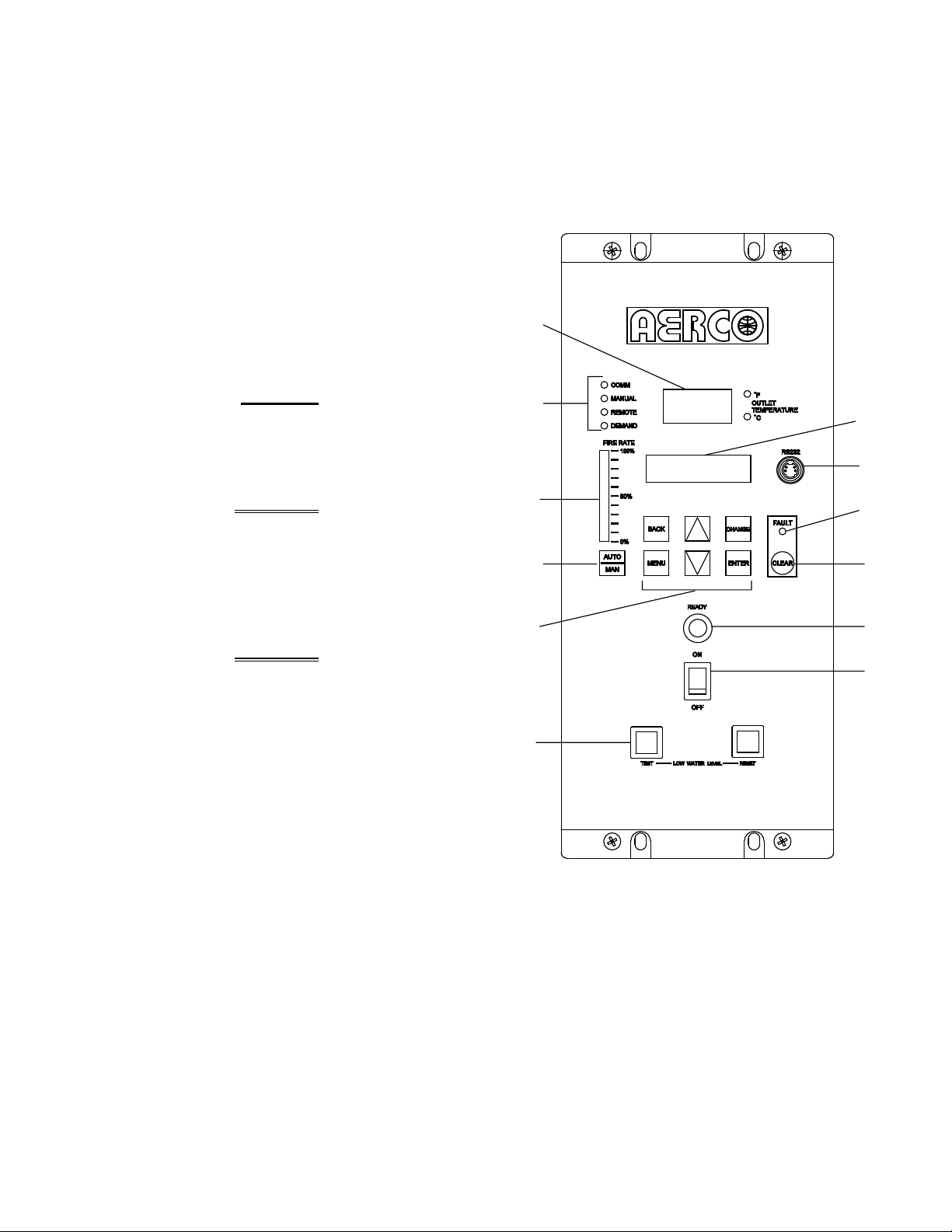
3.2 CONTROL PANEL DESCRIPTION
The Benchmark 3.0 Control Panel shown in
Figure 3-1 contains all of the controls, indicators
and displays necessary to operate, adjust and
troubleshoot the Benchmark 3.0 Boiler. These
operating controls, indicators and displays are
listed and described in Table 3-1. Additional
information on these items are provided in the
individual operating procedures provided in this
Chapter.
Figure 3-1.
Control Panel Front View
3-1

CONTROL PANEL OPERATING PROCEDURES
FUNCTION
Table 3-1 Operating Controls, Indicators and Displays
ITEM
NO.
CONTROL, INDICATOR
OR DISPLAY
1 LED Status Indicators Four Status LEDs indicate the current operating status as
follows:
COMM
MANUAL
REMOTE
DEMAND
OUTLET
2
TEMPERATURE
Display
3 VFD Display Vacuum Fluorescent Display (VFD) consists of 2 lines each
Lights when RS-232 communication is occurring
Lights when the unit is being controlled using the front panel
keypad.
Lights when the unit is being controlled by an external signal
from an Energy Management System
Lights when there is a demand for heat.
3–Digit, 7–Segment LED display continuously displays the
outlet water temperature. The °F or °C LED next to the
display lights to indicate whether the displayed temperature is
in degrees Fahrenheit or degrees Celsius. The °F or °C blinks
when operating in the Deadband Mode.
capable of displaying up to 16 alphanumeric characters. The
information displayed includes:
Startup Messages
Fault Messages
Operating Status Messages
Menu Selection
RS-232 Port
4
FAULT Indicator Red FAULT LED indicator lights when a boiler alarm
5
CLEAR Key Turns off the FAULT indicator and clears the alarm message
6
READY Indicator
7
ON/OFF Switch
8
LOW WATER LEVEL
9
TEST/RESET Switches
Port permits a Laptop Computer or External Modem to be
connected to the unit’s Control Panel.
condition occurs. An alarm message will appear in the VFD.
if the alarm is no longer valid. Lockout type alarms will be
latched and cannot be cleared by simply pressing this key.
Troubleshooting may be required to clear these types of
alarms.
Lights ON/OFF switch is set to ON and all Pre-Purge
conditions have been satisfied.
Enables and disables boiler operation.
Allows operator to test operation of the water level monitor.
Pressing TEST opens the water level probe circuit and
simulates a Low Water Level alarm.
Pressing RESET resets the water level monitor circuit.
Pressing the CLEAR key (item 6) resets the display.
3-2

CONTROL PANEL OPERATING PROCEDURES
FUNCTION
Table 3-1 Operating Controls, Indicators and Displays – Continued
ITEM
NO.
10 MENU Keypad Consists of 6 keys which provide the following functions for
CONTROL, INDICATOR
OR DISPLAY
the Control Panel Menus:
MENU
BACK
▲ (UP) Arrow When in one of the main menu categories (Figure 3-2),
▼ (DOWN) Arrow When in one of the main menu categories (Figure 3-2),
CHANGE
Steps through the main menu categories shown in Figure 3-
2. The Menu categories wrap around in the order shown.
Allows you to go back to the previous menu level without
changing any information. Continuously pressing this key
will bring you back to the default status display in the VFD.
Also, this key allows you to go back to the top of a main
menu category.
pressing the ▲ arrow key will select the displayed menu
category. If the CHANGE key was pressed and the menu
item is flashing, pressing the ▲ arrow key will increment the
selected setting.
pressing this key will select the displayed menu category. If
the CHANGE key was pressed and the menu item is
flashing, pressing the ▼ arrow key will decrement the
selected setting.
Permits a setting to be changed (edited). When the
CHANGE key is pressed, the displayed menu item will begin
to flash. Pressing the ▲ or ▼ arrow key when the item is
flashing will increment or decrement the displayed setting.
11
12
ENTER
AUTO/MAN Switch
VALVE POSITION
Bargraph
Saves the modified menu settings in memory. The display
will stop flashing.
This switch toggles the boiler between the Automatic and
Manual modes of operation. When in the Manual (MAN)
mode, the front panel controls are enabled and the
MANUAL status LED lights.
When in the Automatic (AUTO) mode, the MANUAL status
LED will be off and the front panel controls disabled.
20 segment red LED bargraph continuously shows the
Air/Fuel Valve position in 5% increments from 0 to 100%
3-3
CONTROL PANEL OPERATING PROCEDURES
OPERATING
SETUP
CONFIGURATION
TUNING
COMBUSTION CAL
CALIBRATION
(NOT USED IN THIS O & M)
LEVEL 2 PWD
LEVEL 1 PWD
DIAGNOSTICS
(NOT USED IN THIS O & M)
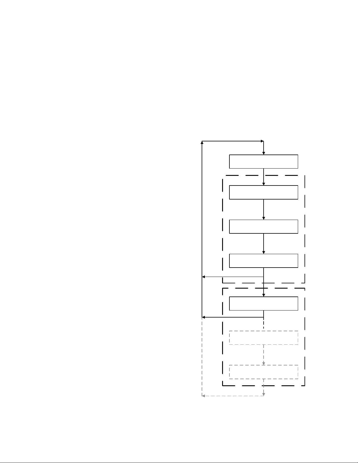
3.3 CONTROL PANEL MENUS
The Control Panel incorporates an extensive
menu structure which permits the operator to set
up, and configure the unit. The menu structure
consists of five major menu categories which are
applicable to this manual. These categories are
shown in Figure 3-2. Each of the menus shown,
contain options which permit operating
parameters to be viewed or changed. The
menus are protected by a password levels to
prevent unauthorized use.
Prior to entering the correct password, the
options contained in the Operation, Setup,
Configuration and Tuning Menu categories can
be viewed. However, with the exception of
Internal Setpoint Temperature (Configuration
Menu), none of the viewable menu options can
be changed.
Once the valid level 1 password (159) is
entered, the options listed in the Setup.
Configuration and Tuning Menus can be viewed
and changed, if desired. The Combustion Cal
Menu is protected by the level 2 password which
is used in Chapter 4 to perform combustion
calibration prior to service use.
display the options in the Bottom-Up
sequence. The menu options will wraparound after the first or last available option
is reached.
6. To change the value or setting of a
displayed menu option, press the CHANGE
key. The displayed option will begin to flash.
Press the ▲ or ▼ arrow key to scroll
through the available menu option choices
for the option to be changed. The menu
option choices do not wrap around.
7. To select and store a changed menu item,
press the ENTER key.
3.3.1 Menu Processing Procedure
Accessing and initiating each menu and option
is accomplished using the Menu Keys shown in
Figure 3-1. Therefore, it is imperative that you
be thoroughly familiar with the following basic
steps before attempting to perform specific
menu procedures.
1. The Control Panel will normally be in the
Operating Menu and the VFD will display the
current unit status. Pressing the ▲ or ▼
arrow key will display the other available
data items in the Operating Menu.
2. Press the MENU key. The display will show
the Setup Menu, which is the next menu
category shown in Figure 3-2. This menu
contains the Password option which must be
entered if other menu options will be
changed.
3. Continue pressing the MENU key until the
desired menu is displayed.
4. With the desired menu displayed, press the
▲ or ▼ arrow key. The first option in the
selected menu will be displayed.
5. Continue to press the ▲ or ▼ arrow key
until the desired menu option is displayed.
Pressing the ▲ arrow key will display the
available menu options in the Top-Down
sequence. Pressing the ▼ arrow key will
3-4
Figure 3-2. Menu Structure

CONTROL PANEL OPERATING PROCEDURES
Available Choices or Limits
NOTE
The following paragraphs provide brief
descriptions of the options contained in each
menu. Refer to Appendix A for detailed
descriptions of each menu option. Refer to
Appendix B for listings and descriptions of
displayed startup, status and error
messages.
3.4 OPERATING MENU
The Operating Menu displays a number of key
operating parameters for the unit as listed in
Table 3-2. This menu is “Read-Only” and does
not allow personnel to change or adjust any
displayed items. Since this menu is “Read-Only”,
it can be viewed at any time without entering a
password. Pressing the ▲ arrow key to display
the menu items in the order listed (Top-Down).
Pressing the ▼ arrow key will display the menu
items in reverse order (Bottom-Up).
3.5 SETUP MENU
The Setup Menu (Table 3-3) permits the
operator to enter the unit password (159) which
is required to change the menu options. To
prevent unauthorized use, the password will
time-out after 1 hour. Therefore, the correct
password must be reentered when required. In
addition to permitting password entries, the
Setup Menu is also used to enter date and time,
units of temperature measurements and entries
required for external communication and control
of the unit via the RS-232 port. A view-only
software version display is also provided to
indicate the current Control Box software
version.
NOTE
The Outdoor Temp display item shown with
an asterisk in Table 3-2 will not be displayed
unless the Outdoor Sensor function has
been enabled in the Configuration Menu
(Table 3-4).
Table 3-2. Operating Menu
Menu Item Display Minimum Maximum Default
Status Message
Active Setpoint 40°F 240°F
AIR Temp -70°F 245°F
Outdoor Temp* -70°F 130°F
Valve Position In 0% Max Valve
Position
Flame Strength 0% 100%
Run Cycles 0 999,999,999
Run Hours 0 999,999,999
Fault Log 0 9 0
3-5

CONTROL PANEL OPERATING PROCEDURES
Available Choices or Limits
Menu Item Display
Minimum
Maximum
Default
Available Choices or Limits
Menu Item Display
Minimum
Maximum
Default
Table 3-3. Setup Menu
Passsword 0 9999 0
Language English English
Time 12:00 am 11:59 pm
Date 01/01/00 12/31/99
Unit of Temp Fahrenheit or Celsius Fahrenheit
Comm Address 0 127 0
Baud Rate 2400, 4800, 9600, 19.2K 9600
Software Ver 0.00 Ver 9.99
3.6 CONFIGURATION MENU
The Configuration Menu shown in Table 3-4
permits adjustment of the Internal Setpoint
(Setpt) temperature regardless of whether the
valid password has been entered. Setpt is
required for operation in the Constant Setpoint
mode. The remaining options in this menu
require the valid password to be entered, prior to
changing existing entries. This menu contains a
number of other configuration settings which
may or may not be displayed, depending on the
current operating mode setting.
Table 3-4. Configuration Menu
Internal Setpt Lo Temp Limit Hi Temp Limit 130°F
Unit Type KC Boiler, KC Boiler LN,
BMK Boiler, BMK Boiler LN,
BMK Boiler Dual, KC Water
Heater, KC Water Heater LN,
Water Heater 2010
Unit Size 0.5 MBTU, 1.0 MBTU
1.5 MBTU, 2.0 MBTU
3.0 MBTU, 3.5 MBTU
4.0 MBTU, 5.0 MBTU
Fuel Type Natural Gas, Propane Natural Gas
Boiler Mode Constant Setpoint,
Remote Setpoint,
Combination
Outdoor Reset
NOTE
The Configuration Menu settings shown in
Table 3-4 are Factory-Set in accordance
with the requirements specified for each
individual order. Therefore, under normal
operating conditions, no changes will be
required.
BMK Boiler
LN
3.0 MBTU
6.0 MBTU
Constant
Setpoint
Direct Drive
3-6
 Loading...