

Page 1
Instruction
GF-116
No.
AERCO INTERNATIONAL, Inc., Northvale, New Jersey, 07647 USA
Installation, Operation
& Maintenance Instructions
Benchmark 3.0LN
Series
Gas Fired
Low NOx
Boiler System
Condensing, Modulating
Forced Draft, Hot Wa t e r Boiler
3,000,000 BTU/H Input
Applicable for Serial Numbers G-10-1473 and above
Printed in U.S.A. REVISED JANUARY 27, 2011
Page 2

Telephone Support
Direct to AERCO Technical Support
(8 to 5 pm EST, Monday through Friday):
1-800-526-0288
AERCO International, Inc.
159 Paris Avenue
Northvale, NJ 07647-0128
www.aerco,com
© AERCO International, Inc., 2011
The information contained in this
installation, operation and maintenance manual is subject to
change without notice from
AERCO International, Inc.
AERCO makes no warranty of any
kind with respect to this material,
including but not limited to implied
warranties of merchantability and
fitness for a particular application.
AERCO International is not liable
for errors appearing in this
manual. Nor for incidental or
consequential damages occurring
in connection with the furnishing,
performance, or use of this
material.
Page 3

CONTENTS
GF-116 - AERCO BENCHMARK 3.0LN GAS FIRED LOW NOx BOILER
Operating & Maintenance Instructions
FOREWORD A
Chapter 1 – SAFETY PRECAUTIONS 1-1
Para. Subject Page
1-1 Warnings & Cautions 1-1
1-2 Emergency Shutdown 1-2
Chapter 2 – INSTALLATION 2-1
Para. Subject Page
2.1 Introduction 2-1
2.2 Receiving the Unit 2-1
2.3 Unpacking 2-1
2.4 Site Preparation 2-1
2.5 Supply and Return Piping 2-3
2.6 Condensate Drains 2-3
2.7 Gas Supply Piping 2-5
2.8 AC Electrical Power Wiring 2-6
Para. Subject Page
1-3 Prolonged Shutdown 1-2
Para. Subject Page
2.9 Modes of Operation and Field
Control Wiring
2.10 I/O Box Connections 2-9
2.11 Auxiliary Relay Contacts 2-11
2.12 Flue Gas Vent Installation 2-11
2.13 Combustion Air 2-11
2-7
Chapter 3 – CONTROL PANEL OPERATING PROCEDURES 3-1
Para. Subject Page
3.1 Introduction 3-1
3.2 Control Panel Description 3-1
3.3 Control Panel Menus 3-4
3.4 Operating Menu 3-5
3.5 Setup Menu 3-5
Para. Subject Page
3.6 Configuration Menu 3-6
3.7 Tuning Menu 3-8
3.8 Combustion Cal Menu 3-8
3.9 Start Sequence 3-8
3.10 Start/Stop Levels 3-10
Chapter 4 – INITIAL START-UP 4-1
Para. Subject Page
4.1 Initial Startup Requirements 4-1
4.2 Tools and Instruments for
Combustion Calibration
4.3 Natural Gas Combustion
Calibration
4-1
4-2
Para. Subject Page
4.4 Unit Reassembly 4-6
4.5 Over-Temperature Limit Switch 4-6
i
Page 4

CONTENTS
Chapter 5 – MODE OF OPERATION 5-1
Para. Subject Page
5.1 Introduction 5-1
5.2 Indoor/Outdoor Reset Mode 5-1
5.3 Constant Setpoint Mode 5-2
5.4 Remote Setpoint Mode 5-2
5.5 Direct Drive Modes 5-3
Para. Subject Page
5.6 Boiler Management System
(BMS)
5.7 Combination Control System
(CCS)
5-4
5-5
Chapter 6 – SAFETY DEVICE TESTING PROCEDURES 6-1
Para. Subject Page
6.1 Testing of Safety Devices 6-1
6.2 Low Gas Pressure Fault Test 6-1
6.3 High Gas Pressure Test 6-2
6.4 Low Water Level Fault Test 6-2
6.5 Water Temperature Fault Test 6-2
6.6 Interlock Tests 6-3
6.7 Flame Fault Test 6-3
Para. Subject Page
6.8 Air Flow Fault Test 6-4
6.9 SSOV Proof of Closure Switch 6-4
6.10 Purge Switch Open During
Purge
6.11 Ignition Switch Open During
Ignition
6.12 Safety Pressure Relief Valve
Test
6-5
6-5
6-6
Chapter 7 – MAINTENANCE REQUIREMENTS 7-1
Para. Subject Page
7.1 Maintenance Schedule 7-1
7.2 Ignitor-Injector 7-1
7.3 Flame Detector 7-2
7.4 Combustion Calibration 7-3
7.5 Safety Device Testing 7-3
7.6 Burner Assembly Inspection 7-3
Para. Subject Page
7.7 Condensate Drain Trap 7-4
7.8 Shutting the Boiler Down For An
Extended Period of Time
7.9 Placing The Boiler Back In
Service After A Prolonged
Shutdown
7-6
7-6
Chapter 8 – TROUBLESHOOTING GUIDE 8-1
Para. Subject Page
8.1 Introduction 8-1
Para. Subject Page
ii
Page 5

CONTENTS
Chapter 9 - RS232 COMMUNICATION 9-1
Para. Subject Page
9.1 Introduction 9-1
9-2 RS232 Communication Setup 9-1
APPENDICES
App Subject Page
A Boiler Menu Item Descriptions A-1
B Startup, Status and Fault
Messages
C Temperature Sensor Resistance
Chart
D Indoor/Outdoor Reset Ratio
Charts
E Boiler Default Settings E-1
F Dimensional and Part Drawings F-1
B-1
C-1
D-1
Para. Subject Page
9-3 Menu Processing Utilizing
RS232 Communication
9-4 Data Logging 9-2
App Subject Page
G Piping Drawings G-1
H Wiring Schematics H-1
I Recommended Periodic Testing
Checklist
J Benchmark Control Panel Views J-1
K Recommended Spare Parts K-1
9-1
I-1
WARRANTIES W-1
iii
Page 6

Page 7

FOREWORD
Foreword
The AERCO Benchmark 3.0LN Boiler is a modulating unit. It represents a true industry advance
that meets the needs of today's energy and env ironmental concer ns. Desig ned for application
in any closed loop hydronic system, the Benchmark's modulating capability relates energy input
directly t o f luctuating sy stem loads. T he Benchm ark 3. 0, w ith it s 15: 1 t urn down ratio and
condensing capabilit y, pr ovides ex tremely hig h ef ficiencies and makes it ideally suited for
modern low temperature, as well as, conventional heating systems.
The Benchmark 3.0 operates at inputs ranging from 200,000 BTU/hr. to 3,000,000 BTU/hr. The
output of t he boiler is a f unction of the unit ’s f iring r ate and r eturn w ater t emperature. O utput
ranges from 198,000 BTU/hr. to 2,900,000 BTU/hr., depending on operating conditions.
When installed and oper ated in accor dance w ith t his I nstruction M anual, t he Benchm ark 3. 0
Boiler complies with the NOx emission standards outlined in:
• South Coast Air Quality Management District (SCAQMD), Rule 1146.1
Whether used in sing ular or modular ar rangements, t he Benchmark 3. 0 of fers the maximum
flexibility in v enting with m inimum inst allation space requirements. The Benchmark's advanced
electronics are available in sev eral select able m odes of oper ation of fering t he m ost ef ficient
operating methods and energy management system integration.
For service or parts, contact your local sales representative or AERCO INTERNATIONAL.
NAME:
ORGANIZATION:
ADDRESS:
TELEPHONE:
INSTALLATION DATE: _____________________________________________
A
Page 8

Page 9

SAFETY PRECAUTIONS
CHAPTER 1 SAFETY PRECAUTIONS
1.1 WARNINGS & CAUTIONS
Installers and o perating p ersonnel M UST, at all
times, obs erve al l s afety r egulations. T he
following warnings and cautions are general and
must be gi ven th e s ame attention as s pecific
precautions i ncluded in t hese ins tructions. In
addition to all t he r equirements inc luded in th is
AERCO Ins truction Man ual, th e ins tallation of
units MUST conform with loc al bu ilding codes,
or, in th e absence of local c odes, ANSI Z223.1
(National Fuel Gas Code P ublication No. NF PA-
54). Where ASM E CS D-1 is r equired b y local
jurisdiction, the i nstallation m ust c onform to
CSD-1.
Where appl icable, th e equipment s hall be
installed in a ccordance w ith t he cu rrent
Installation Co de f or G as Bur ning Appliances
and Equipment, CG A B149, an d a pplicable
Provincial regulations for the class; which should
be ca refully f ollowed in all ca ses. Authorities
having j urisdiction s hould be c onsulted before
installations are made.
IMPORTANT
This I nstruction M anual is an int egral
part o f the pr oduct a nd m ust be
maintained in legible condition. It must
be g iven t o t he user b y t he inst aller
and k ept in a sa fe pla ce for future
reference.
WARNINGS!
MUST BE OBSERVED TO PREVENT
SERIOUS INJURY.
WARNING!
BEFORE ATT EMPTING TO PERFORM ANY MAINTENANCE ON THE
UNIT, SHU T OFF AL L G AS AND
ELECTRICAL INPUTS TO THE UNIT.
WARNING!
DO NOT USE MATCHES, CANDLES,
FLAMES, OR OTHER SOURCES O F
IGNITION TO CHECK FO R G AS
LEAKS.
WARNING!
FLUIDS UNDER PRE SSURE MAY
CAUSE I NJURY T O PERSO NNEL
OR DAM AGE TO EQUIPMENT
WHEN RELEASED. BE SURE T O
SHUT O FF ALL I NCOMING AND
OUTGOING W ATER SHUTOFF
VALVES. CAREFULLY DECREASE
ALL T RAPPED PRE SSURES T O
ZERO BEFO RE P ERFORMING
MAINTENANCE.
WARNING!
ELECTRICAL VO LTAGES UP T O
120 VAC MAY BE US ED I N T HIS
EQUIPMENT. T HEREFORE T HE
COVER O N THE UNIT ’S PO WER
BOX ( LOCATED BEHI ND T HE
FRONT PANEL DOO R) M UST BE
INSTALLED AT ALL TIMES, EXCEPT
DURING M AINTENANCE AND
SERVICING.
CAUTIONS!
Must be obser ved t o pr event
equipment da mage or loss o f
operating effectiveness.
CAUTION!
Many soaps used f or gas pipe leak
testing a re co rrosive to me tals. The
piping must
clean water a fter leak checks hav e
been completed.
be r insed t horoughly with
WARNING!
THE EX HAUST VENT PIPE OF THE
UNIT OPERATES UNDER A
POSITIVE PRESSURE AND T HEREFORE MUST BE C OMPLETELY
SEALED T O PREVENT LEAKAG E
OF COMBUSTION PRODUCTS INTO
LIVING SPACES.
CAUTION!
DO NOT use this boiler if any part has
been under w ater. Cal l a q ualified
service t echnician t o inspect and
replace any par t that ha s been under
water.
1-1
Page 10
SAFETY PRECAUTIONS
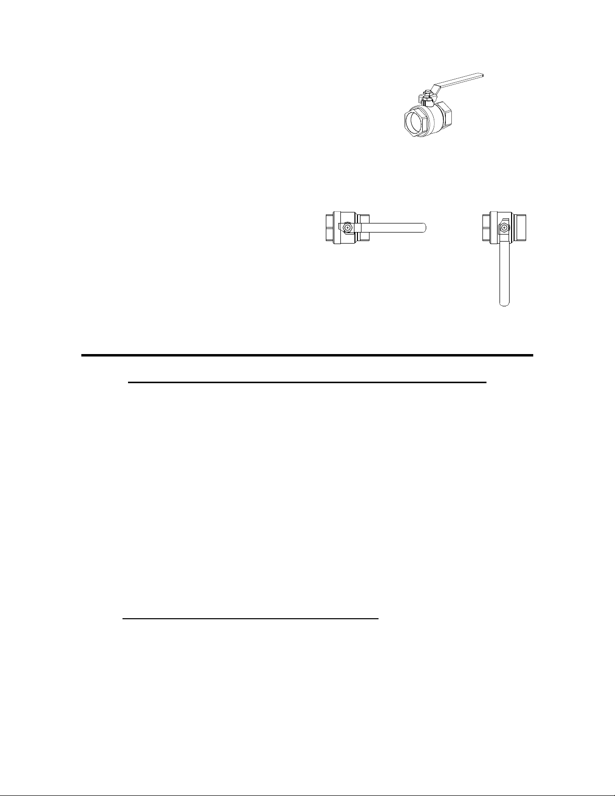
1.2 EMERGENCY SHUTDOWN
If over heating occurs or th e gas s upply f ails to
shut of f, c lose the m anual g as s hutoff val ve
(Figure 1-1) located external to the unit.
IMPORTANT
The Ins taller m ust identif y and indicate
the loc ation of the e mergency s hutdown
manual gas valve to operating personnel.
MANUAL GAS SHUTOFF VALVE
VALVE OPEN
VALVE CLOSED
1.3 PROLONGED SHUTDOWN
After pr olonged s hutdown, it is r ecommended
that the startup procedures in Chapter 4 and the
safety device test pr ocedures in C hapter 6 of
this m anual be performed, to ver ify a ll s ystemoperating parameters. If there is an emergency,
turn of f the elec trical p ower s upply to th e
AERCO b oiler a nd c lose t he m anual g as v alve
located ups tream the unit . T he ins taller m ust
identify the emergency shut-off device.
Figure 1-1
Manual Gas Shutoff Valve
IMPORTANT – FOR MASSACHUSETTS INSTALLATIONS ONLY
Boiler Ins tallations within t he Com monwealth of Ma ssachusetts must c onform to the f ollowing
requirements:
• Boiler must be installed by a plumber or a gas fitter who is licensed within the Commonwealth of
Massachusetts.
• Prior to u nit operation, the c omplete gas train and a ll connections must be lea k tested using a
non-corrosive soap.
• If a gl ycol s olution is us ed as anti- freeze protection, a b ackflow pr eventer must be ins talled
upstream of the Fill/Makeup Valve.
• The vent termination must be located a minimum of 4 feet above grade level.
• If side-wall venting is used, the installation must conform to the following requirements extracted
from 248 CMR 5.08 (2):
(a) For all side wall horizontally vented gas fueled equipment installed in every dwelling, building or
structure used in whole or in part for residential purposes, including those owned or operated by the
Commonwealth and where the side wall exhaust vent termination is less than seven (7) feet above
finished grade in the area of the venting, including but not limited to decks and porches, the following
requirements shall be satisfied:
1-2
1. INSTALLATION OF CARBON MONOXIDE DETECTORS
side wall horizontal vented gas fueled equipment, the installing plumber or gasfitter shall observe
that a hard wired carbon monoxide detector with an alarm and battery back-up is installed on the
floor level where the gas equipment is to be installed. In addition, the installing plumber or
gasfitter shall observe that a battery operated or hard wired carbon monoxide detector with an
alarm is installed on each additional level of the dwelling, building or structure served by the side
wall horizontal vented gas fueled equipment. It shall be the responsibility of the property owner to
secure the services of qualified licensed professionals for the installation of hard wired carbon
monoxide detectors.
. At the time of installation of the
Page 11

Extracted Information From 248 CMR 5.08 (2) – Continued
a. In the event that the side wall horizontally vented gas fueled equipment is installed in
a crawl space or an attic, the hard wired carbon monoxide detector with alarm and
battery back-up may be installed on the next adjacent floor level.
b. In the event that the requirements of this subdivision can not be met at the time of
completion of installation, the owner shall have a period of thirty (30) days to comply with
the above requirements; provided, however, that during said thirty (30) day period, a
battery operated carbon monoxide detector with an alarm shall be installed.
SAFETY PRECAUTIONS
2. APPROVED CARBON MONOXIDE DETECTORS.
required in accordance with the above provisions shall comply with NFPA 720 and be ANSI/UL
2034 listed and IAS certified.
3. SIGNAGE
of the building at a minimum height of eight (8) feet above grade directly in line with the exhaust
vent terminal for the horizontally vented gas fueled heating appliance or equipment. The sign
shall read, in print size no less than one-half (1/2) inch in size, "GAS VENT DIRECTLY BELOW.
KEEP CLEAR OF ALL OBSTRUCTIONS".
4. INSPECTION
equipment shall not approve the installation unless, upon inspection, the inspector observes
carbon monoxide detectors and signage installed in accordance with the provisions of 248 CMR
5.08(2)(a)1 through 4.
(b) EXEMPTIONS
1. The equipment listed in Chapter 10 entitled "Equipment Not Required To Be Vented" in the
most current edition of NFPA 54 as adopted by the Board; and
2. Product Approved side wall horizontally vented gas fueled equipment installed in a room or
structure separate from the dwelling, building or structure used in whole or in part for residential
purposes.
(c) MANUFACTURER REQUIREMENTS - GAS EQUIPMENT VENTING SYSTEM PROVIDED.
the manufacturer of Product Approved side wall horizontally vented gas equipment provides a venting
system design or venting system components with the equipment, the instructions provided by the
manufacturer for installation of the equipment and the venting system shall include:
1. Detailed instructions for the installation of the venting system design or the venting system
components; and
2. A complete parts list for the venting system design or venting system.
. A metal or plastic identification plate shall be permanently mounted to the exterior
. The state or local gas inspector of the side wall horizontally vented gas fueled
: The following equipment is exempt from 248 CMR 5.08(2)(a)1 through 4:
Each carbon monoxide detector as
When
(d) MANUFACTURER REQUIREMENTS - GAS EQUIPMENT VENTING SYSTEM NOT PROVIDED.
When the manufacturer of a Product Approved side wall horizontally vented gas fueled equipment does
not provide the parts for venting the flue gases, but identifies "special venting systems", the following
requirements shall be satisfied by the manufacturer:
1. The identification of each "special venting system" shall include the listing of either the
website, phone number or manufacturer’s address where the venting system installation
instructions can be obtained, and
2. The "special venting systems" shall be Product Approved by the Board, and the instructions
for that system shall include a parts list and detailed installation instructions.
(e) A copy of all installation instructions for the Product Approved side wall horizontally vented gas fueled
equipment and all the venting instructions, parts lists and/or design instructions for the venting system
shall remain with the appliance or equipment at the completion of the installation.
_______________________________ [End of Extracted Information From 248 CMR 5.08 (2)]
1-3
Page 12

Page 13

INSTALLATION
CHAPTER 2 INSTALLATION
2.1 INTRODUCTION
This Chapt er pr ovides t he d escriptions a nd
procedures nec essary t o unpack, ins pect an d
install th e AERCO Benchmark 3.0 Boi ler. Br ief
descriptions are also provided for each available
mode of oper ation. Det ailed procedures f or
implementing th ese m odes ar e pr ovided in
Chapter 5.
2.2 RECEIVING THE UNIT
Each Benchmark 3.0 S ystem is s hipped as a
single c rated unit. T he s hipping weight is
approximately 2,170 pounds. T he un it m ust be
moved w ith the pr oper rigging equ ipment for
safety and to avoid equipment damage. The unit
should b e c ompletely inspected f or e vidence of
shipping damage and shipment completeness at
the t ime of r eceipt f rom the c arrier a nd before
the bill of lading is signed.
NOTE
AERCO is no t r esponsible f or los t or
damaged freight.
Each u nit has a T ip-N-Tell indicator on th e
outside of the crate. This indicates if the unit has
been t urned on its s ide d uring s hipment. If the
Tip-N-Tell indicator is tripped, do not sign for the
shipment. Not e th e information o n t he c arrier’s
paperwork and r equest a f reight c laim and
inspection b y a c laims adj uster bef ore
proceeding. A ny other v isual d amage to t he
packaging m aterials s hould als o be m ade c lear
to the delivering carrier.
2.3 UNPACKING
Carefully unpack the unit tak ing c are not to
damage the un it enclosure when c utting away
packaging materials
• Pr essure/Temperature Gauge
• Spar e Ignitor-Injector
• Spare Flame Detector
• ASME Pressure Relief Valve
• Condensate Drain Trap & Adapter `
• 2” Gas Supply Shutoff Valve
When or dered, o ptional accessories may be
packed separately, pac ked with in the boiler
shipping c ontainer, or m ay be i nstalled on th e
boiler. A ny s tandard or opti onal ac cessories
shipped loose should be identified and stored in
a safe place until ready for installation or use.
2.4 SITE PREPARATION.
Ensure t hat t he s ite s elected f or ins tallation of
the Benchmark 3.0 Boiler includes:
• Access to AC Inp ut Po wer corresponding to
the or dered po wer c onfiguration. T he
available power configurations are:
• 208 VAC, 3-Phase, 60 Hz @ 20 A
• 460 VAC, 3-Phase, 60 Hz @ 15 A
• Access to Natur al G as line at a m inimum
static pressure of 3.5” W.C.(FM) or 4.0” W.C.
(IRI). M aximum static p ressure must n ot
exceed 2 psi.
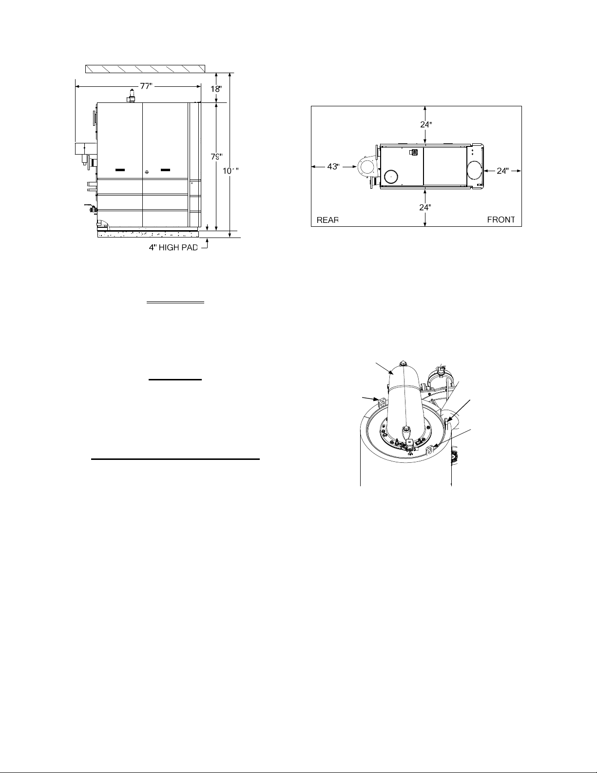
2.4.1 Installation Clearances
The unit m ust be i nstalled with t he prescribed
clearances f or s ervice as shown in F igure 2-1.
The minimum
AERCO, ar e l isted below. Ho wever, if Loc al
Building Cod es r equire a dditional c learances,
these c odes s hall s upersede A ERCO’s
requirements. Mi nimum ac ceptable c learances
required are:
clearance dimensions, required by
A close inspection of the unit should be m ade to
ensure that there is no e vidence of damage not
indicated by the Tip-N-Tell indicator. The freight
carrier s hould b e not ified im mediately if an y
damage is detected.
The f ollowing accessories c ome s tandard with
each un it and ar e eit her pack ed s eparately
within the unit’s packing container or are factory
installed on the boiler:
• Sid es: 24 inches
• Front : 24 inches
• Rear : 43 inches
• T op: 18 inches
All gas piping, water piping and electrical conduit
or c able m ust be ar ranged s o th at t hey d o not
interfere with the r emoval of an y panels, or
inhibit service or maintenance of the unit.
2-1
Page 14
INSTALLATION
Figure 2-1 Benchmark 3.0 Boiler Clearances
WARNING
KEEP T HE UNIT AREA CLEAR AND
FREE FRO M ALL C OMBUSTIBLE
MATERIALS AND FLAMMABLE
VAPORS OR LIQUIDS
.
CAUTION
While pac kaged in the shipping
container, the boiler m ust be m oved
by p allet ja ck o r forklift from th e
FRONT ONLY.
FOR MASSACHUSETTS ONLY
For M assachusetts i nstallations, th e
boiler m ust be ins talled by a plum ber
or gas fitter who is licensed within the
Commonwealth of M assachusetts. I n
addition, t he inst allation m ust comply
with all r equirements specif ied in
Chapter 1 (Safety Precautions), pages
1-2 & 1-3.
2.4.2 Setting the Unit
The unit m ust be ins talled on a 4 inc h to 6 inc h
housekeeping pad to ensure proper condensate
drainage. If anc horing th e unit, r efer to the
dimensional dr awings in A ppendix F for anchor
locations. A total of 3 lifting tabs are provided at
the top of the primary heat exchanger as shown
in F igure 2- 2. Ho wever, USE O NLY T ABS 1
AND 2 SHOWN IN FIGURE 2-2 TO MOVE THE
ENTIRE UNIT . T abs 1 and 3 ar e us ed o nly
when r emoving or r eplacing the unit’s pr imary
heat exchanger. Rem ove the f ront t op p anel
from the unit to provide access to the lifting tabs.
2-2
Remove the four (4) lag screws securing the unit
to the s hipping skid. Lift the unit off the s hipping
skid and pos ition it on t he 4 inc h t o 6 inc h
housekeeping c oncrete p ad ( required) in t he
desired location.
BURNER
ASSEMBLY
LIFTING
TAB 1
PRIMARY HEAT
EXCHANGER
LIFTING
TAB 2
LIFTING
TAB 3
Figure 2-2
Lifting Lug Locations
In m ultiple unit installations, it is important to
plan the pos ition of eac h unit i n ad vance.
Sufficient s pace f or pi ping c onnections a nd
future s ervice/maintenance r equirements must
also be taken into consideration. All piping must
include ample provisions for expansion.
If ins talling a Com bination Control Pa nel ( CCP)
system, it is important to identify th e
Combination Mode Boilers in advance and place
them in the pr oper ph ysical loc ation. Ref er to
Chapter 5 f or information o n Combination Mode
Boilers.
Page 15
INSTALLATION
5
Y
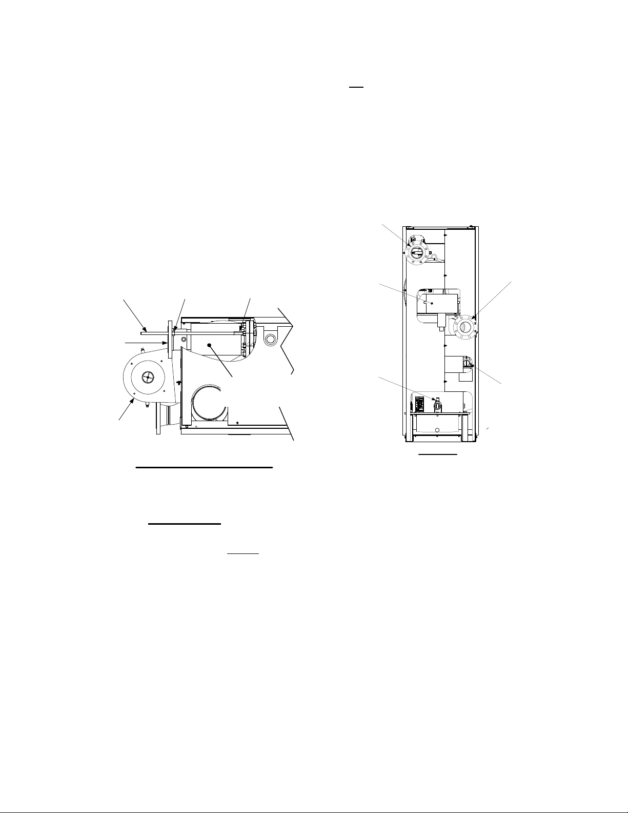
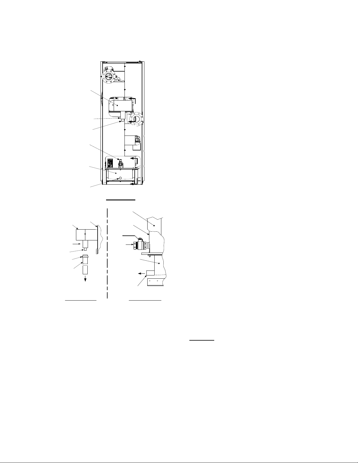
2.4.3 Removal of Support Rod
Prior to ins tallation of w ater supply a nd return
piping, the 24” threaded rod shown in Figure 2-3
must be r emoved. T his r od is installed pr ior to
shipment from the f actory to prevent damage t o
the ins ulated m etal f lex h ose on the hot water
supply outlet of the b oiler. In order to install t he
water s upply piping, th is r od m ust be r emoved
as follows:
1. Refer to Figure 2-3 and back off the hex nut
on the outlet side of the flex hose.
2. Next, disconnect the coupling nut from the
flange stud.
3. Completely remove the threaded rod, hex
nut and coupling nut from the boiler.
5/8-11 x 24" LONG
THREADED ROD
OUTLET
FLANGE
5/8-11
HEX NUT
/8-11
COUPLING NUT
INSULATED
FLEX HOSE
(SEE IMPORTANT
NOTE BELOW)
This c an be eas ily accomplished b y r emoving
the top
panel nearest to the front of the unit.
2.5 SUPPLY AND RETURN PIPING
The Benc hmark 3.0 B oiler uti lizes 4” 1 50#
flanges f or the water s ystem s upply a nd r eturn
piping connections. The ph ysical location of the
supply and return piping connections are on the
rear of the unit as shown in Figure 2-4. Refer to
Appendix F, Dr awing A P-A-811 f or ad ditional
dimensional data.
BOILER SUPPL
4" – 150# FLANGED
CONNECTION
BOILER RETURN
EXHAUST
MANIFOLD
SHELL DRAIN
VALVE
4" – 150# FLANGED
CONNECTION
2" GAS INLET
CONNECTION
EXHAUST
MANIFOLD
PARTIAL TOP VIEW - REAR
Figure 2-3
Location of Threaded Support Rod
IMPORTANT
THE IN SULATED F LEX H OSE
SHOWN IN FIG URE 2- 3 M UST
LEVEL O R SLO PING UPWARD AS
IT EXITS THE BOILER. FAILURE TO
PROPERLY PO SITION T HIS HO SE
MAY CAUSE I NEFFECTIVE AI R
ELIMINATION R ESULTING IN E LEVATED T EMPERATURES THAT
COULD CO MPROMISE T HE TOP
HEAD GASKET.
2.4.4 Removal of Strap and Packing
Material From Heat Exchanger
Prior to c onnecting th e ex ternal g as s upply or
electrical po wer to t he unit. the s trap and
packing material m ust be r emoved f rom the top
of the primary he at exchanger. T his m aterial is
located i n the area of the ig nitor-injector an d
staged ignition solenoid on the b urner assembly
BE
REAR VIEW
Figure 2-4
Supply and Return Locations
2.6 CONDENSATE DRAINS
The Benc hmark 3.0 Boi ler is d esigned t o
condense water vapor f rom the f lue pr oducts.
Therefore, the ins tallation must have pr ovisions
for suitable condensate drainage or collection.
Two condensate drain connections are provided
on th e r ear of the u nit as shown i n F igure 2- 5.
One dr ain connection is located o n the ex haust
manifold and th e oth er is loc ated on th e
connecting manifold.
The drain at th e bottom of the ex haust manifold
also i ncludes a c ondensate tr ap c ontaining a
float assembly. When condensate collects in the
exhaust m anifold, th e f loat r ises, ther eby
allowing i t to dis charge thr ough t he dr ain
opening. T he dr ain p ipe loc ated on t he
connecting m anifold m ust be c onnected to a
second c ondensate tr ap whic h is pac ked
separately within the unit’s shipping container.
2-3
Page 16
INSTALLATION
The pr ocedures to install and c onnect b oth of
the c ondensate drains ar e pr ovided i n
paragraphs 2.6.1 and 2.6.2.
EXHAUST
MANIFOLD
CONDENSATE
TRAP
DRAIN
SHELL DRAIN
VALVE
A
A
B
CONNECTING
MANIFOLD
EXHAUST
MANIFOLD
DRAIN
FRAME
REAR VIEW
UNIT
UNIT
FRAME
SHELL
B
2.6.2 Connecting Manifold Condensate
Drain
The c onnecting m anifold drain pi pe s hown i n
Figure 2-5, View B – B m ust be c onnected to a
separate c ondensate drain tr ap ex ternal t o th e
unit. T his c ondensate tr ap ( part n o. 24060) is
supplied w ith the un it along w ith a trap adapter
and a 3/4” NPT x 5” long n ipple. Refer to Figure
2-6 and install the trap as follows:
NOTE
The c ondensate tr ap d escribed in the
following s teps c an be installed o n t he
floor behind the unit as shown in Figure 2-
6. Ensure that the condensate trap inlet is
level with or be low t he c onnecting
manifold drain pipe. Ensure that the outlet
hose f rom the tr ap s lopes awa y ( down)
from the trap.
1. Apply Teflon tape to the threads of the 3/4” x
5” long nipple provided with the boiler.
2. Attach t he 3/4” N PT nip ple b etween th e
condensate trap inl et and the tr ap ada ptor
(Figure 2-6).
3. Attach another 3/4” NPT nipple (not supplied) to the condensate trap outlet on the
lower part of the trap.
CONDENSATE
TRAP
DRAIN
HOSE
CLAMP
1" I.D.
HOSE
VIEW “A - A”
TO FLOOR
DRAIN
DRAIN
VALVE
CONNECTING
MANIFOLD
TO
CONDENSATE
TRAP
CONDENSATE
DRAIN PIPE
VIEW “B - B”
Figure 2-5
Condensate Drain Connection Location
2.6.1 Exhaust Manifold Condensate
Drain
Refer to F igure 2- 5, V iew A – A a nd install as
follows:
1. Connect a length of 1 inch I.D. hose (part no.
91030) to the drain on the exhaust manifold
and secure it in place with a hose clamp.
2. Route the hose to a nearby floor drain.
4. Connect the condensate trap and adaptor to
the connecting manifold drain pipe. Position
the trap so it is level and then tighten the
thumb screw on the adaptor.
5. Place a suitable support under the
condensate trap to maintain the trap in the
level position.
6. Connect a length of 1” I.D. polypropylene hose
to the outlet side of the condensate trap and
route it to a nearby floor drain.
If desired, a Tee fitting may be used to connect the
two drain ho ses from the exhaust m anifold and the
outlet side
of the of the condensate trap attached to
the connecting manifold.
If a floor drain is n ot available, a condensate pump
can be u sed to r emove the condensate to drain.
The m aximum co ndensate flow r ate i s 20 GPH.
The condensate dr ain t rap, a ssociated fittings a nd
drain lines m ust be removable fo r routine
maintenance.
2-4
Page 17
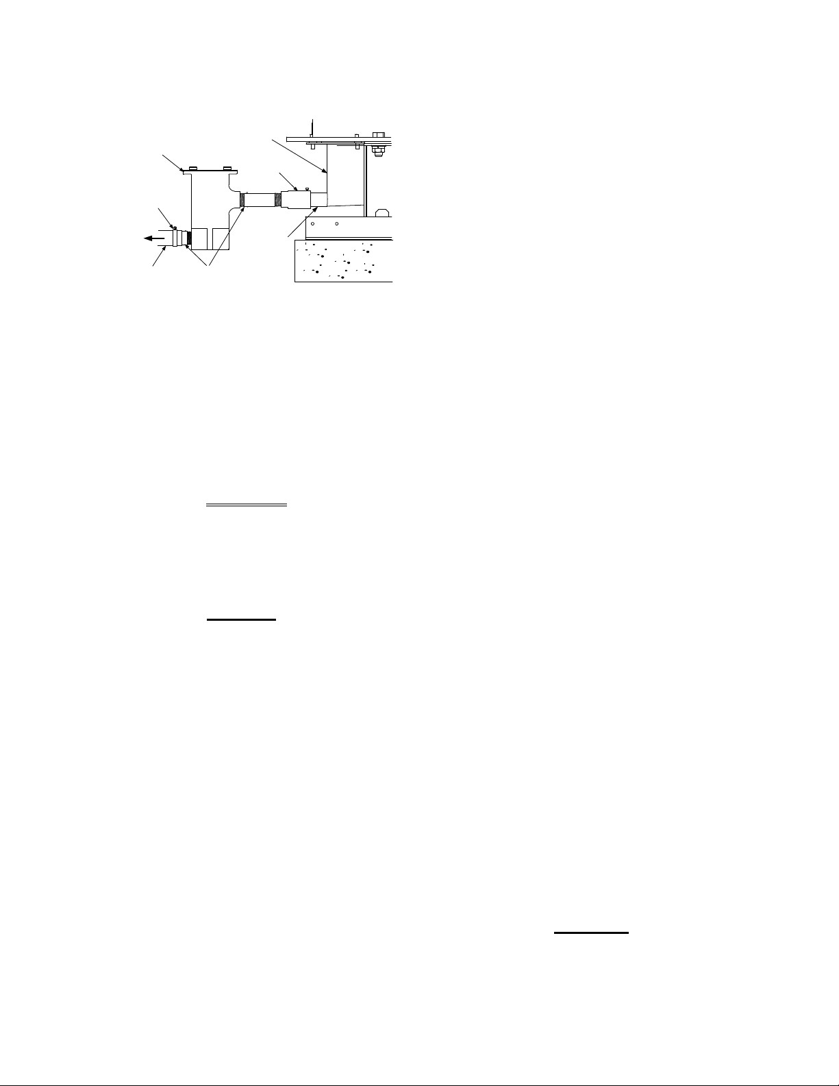
INSTALLATION
CONNECTING
CONDENSATE
TRAP
CLAMP
TO
FLOOR
DRAIN
1" I.D.
HOSE
MANIFOLD
3/4" NPT
NIPPLES
ADAPTOR
DRAIN
PIPE
Figure 2-6
Condensate Trap Installation
2.7 GAS SUPPLY PIPING
The AERCO Benchmark 3.0 Gas Components
and S upply Des ign G uide, G F-3030 m ust be
consulted prior to designing or installing any gas
supply piping.
WARNING
NEVER US E MATCHES, CANDLES,
FLAMES O R OT HER S OURCES O F
IGNITION TO CHECK FO R G AS
LEAKS
Many soaps used f or gas pipe leak
testing are corrosive to metals. There-
fore, piping must be rinsed thoroughly
with clean water af ter leak chec ks
have been completed.
All gas piping must be ar ranged so that it
does not i nterfere with r emoval of an y
covers, in hibit s ervice/maintenance, or
restrict ac cess bet ween the unit a nd
walls, or another unit.
A 2 inch gas inlet c onnection is l ocated o n th e
rear of the unit as shown in Figure 2-4.
Prior to i nstallation, al l p ipes s hould be d eburred and internally cleared of any scale, metal
chips or oth er f oreign particles. Do Not install
any f lexible c onnectors or unap proved gas
fittings. Piping must be supported from the f loor,
ceiling or walls only and m ust not be s upported
by the unit.
.
CAUTION
NOTE
A s uitable p iping c ompound, appr oved f or us e
with natur al gas , should b e used. An y excess
must be wipe d of f to prevent c logging of
components.
To avoid unit damage when pressure testing gas
piping, is olate the unit f rom the gas s upply
piping. At no t ime s hould the g as pr essure
applied to th e un it ex ceed 2 ps i. Leak tes t al l
external p iping th oroughly us ing a s oap a nd
water s olution or s uitable equivalent. T he g as
piping used must meet all applicable codes.
2.7.1 Gas Supply Specification
The gas s upply input s pecifications to the unit
for Natural Gas are as follows:
The m aximum static pr essure to th e unit m ust
not exceed 2 psi. The gas supply pressure to the
unit m ust be of s ufficient c apacity to provide
3000 c fh whi le m aintaining the gas pr essure at
3.5” W.C. for FM or 4.0” for IRI gas trains.
2.7.2 Manual Gas Shutoff Valve
A manual shut-off valve must be ins talled in the
gas supply line upstream of the Boiler as shown
in Figure 2-7. Maximum allowable gas pressure
to the Boiler is 2 psi
NOTE
Paragraph 2.7. 3 applies onl y to bo lier
installations with in t he Co mmonwealth of
Massachusetts.
2.7.3 External Gas Supply Regulator
For Mas sachusetts installations, a m andatory
external gas supply regulator must be positioned
as s hown i n F igure 2- 7. T he gas s upply
regulator m ust be pr operly ve nted to out doors.
Consult th e l ocal gas uti lity f or det ailed
requirements c oncerning ve nting of the th e
supply gas regulator.
NOTE
The external regulator must be capable of
regulating 3, 00,000 BTU/HR of natur al
gas while m aintaining a g as pr essure to
the boiler of 3.5” W.C. for FM or 4.0” W.C.
for IRI gas trains.
CAUTION
A lock -up st yle r egulator M UST be
used w hen g as supply pr essure w ill
exceed 14” W.C.
2-5
Page 18
INSTALLATION
2" MANUAL
SHUTOFF
VALVE
NATURAL
GAS
SUPPLY
TERMINAL BLOCK
MANDATORY
REGULATOR FOR
MASSACHUSSETTS
INSTALLATIONS ONLY
DIRT
TRAP
Figure 2-7
Manual Gas Shut-Off Valve Location
2.7.4 IRI Gas Train Kit
The IRI gas tr ain is a n opti onal g as tr ain
configuration which is required in some areas for
code c ompliance or f or ins urance purposes.
The IRI gas train is factory pr e-piped and wired.
See Appendix F, Drawing AP-A-803 for details.
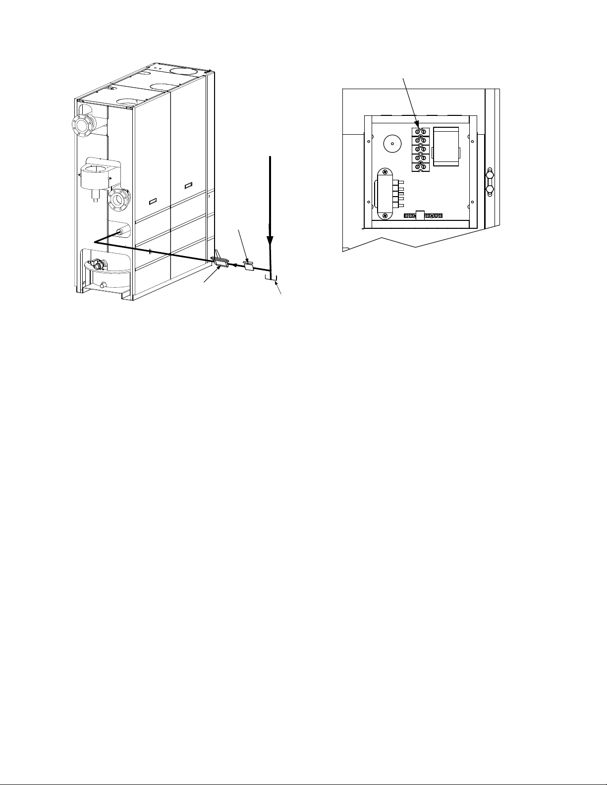
2.8 AC ELECTRICAL POWER WIRING
The AERCO Be nchmark 3.0 E lectrical Po wer
Wiring Guide, GF-3060, must be c onsulted prior
to c onnecting a ny AC po wer wiring t o th e u nit.
External AC po wer connections are made to the
unit inside the Power Box on the f ront pa nel of
the u nit. Remove the f ront door of the unit to
access the P ower Box m ounted directly above
the Co ntrol Box . Loosen the f our Po wer B ox
cover scre ws a nd re move co ver t o a ccess t he
AC t erminal c onnections i nside the P ower Box
(Figure 2-8).
NOTE
All elec trical c onduit a nd hardware m ust
be ins talled s o that it do es not inter fere
with the removal of any unit covers, inhibit
service/maintenance, or pr event ac cess
between the unit and w alls or ano ther
unit.
UPPER RIGHT CORNER OF FRONT PANEL
Figure 2-8
AC Input Terminal Block Location
2.8.1 Electrical Power Requirements
The AERCO Be nchmark 3 .0 Bo iler is ava ilable
in two different AC power configurations:
• 208 VAC/3-Phase/60 @20 amps
• 460 VAC/3-Phase/60 Hz @ 15 amps
Each of the power configurations utilize a Power
Box with a t erminal b lock that m atches the
configuration ordered. The two different terminal
block configurations are shown in F igure 2-9. A
wiring d iagram s howing t he r equired AC po wer
connections is provided on the front cover of the
Power Box.
Each B enchmark 3.0 Boil er must be c onnected
to a d edicated el ectrical circuit. NO O THER
DEVICES SHO ULD B E O N THE SAM E
ELECTRICAL CIRCU IT AS T HE BENCHMARK
BOILER. A m eans f or dis connecting AC p ower
from the unit ( such as a s ervice switch) must be
installed n ear th e un it f or normal oper ation and
maintenance. All e lectrical c onnections s hould
be m ade i n ac cordance with th e Nat ional
Electrical Co de and/or with an y a pplicable local
codes.
For elec trical p ower wiring diagr ams, s ee the
AERCO Benchmark 3.0 El ectrical Power Wiring
Guide, (GF-3060).
2-6
Page 19
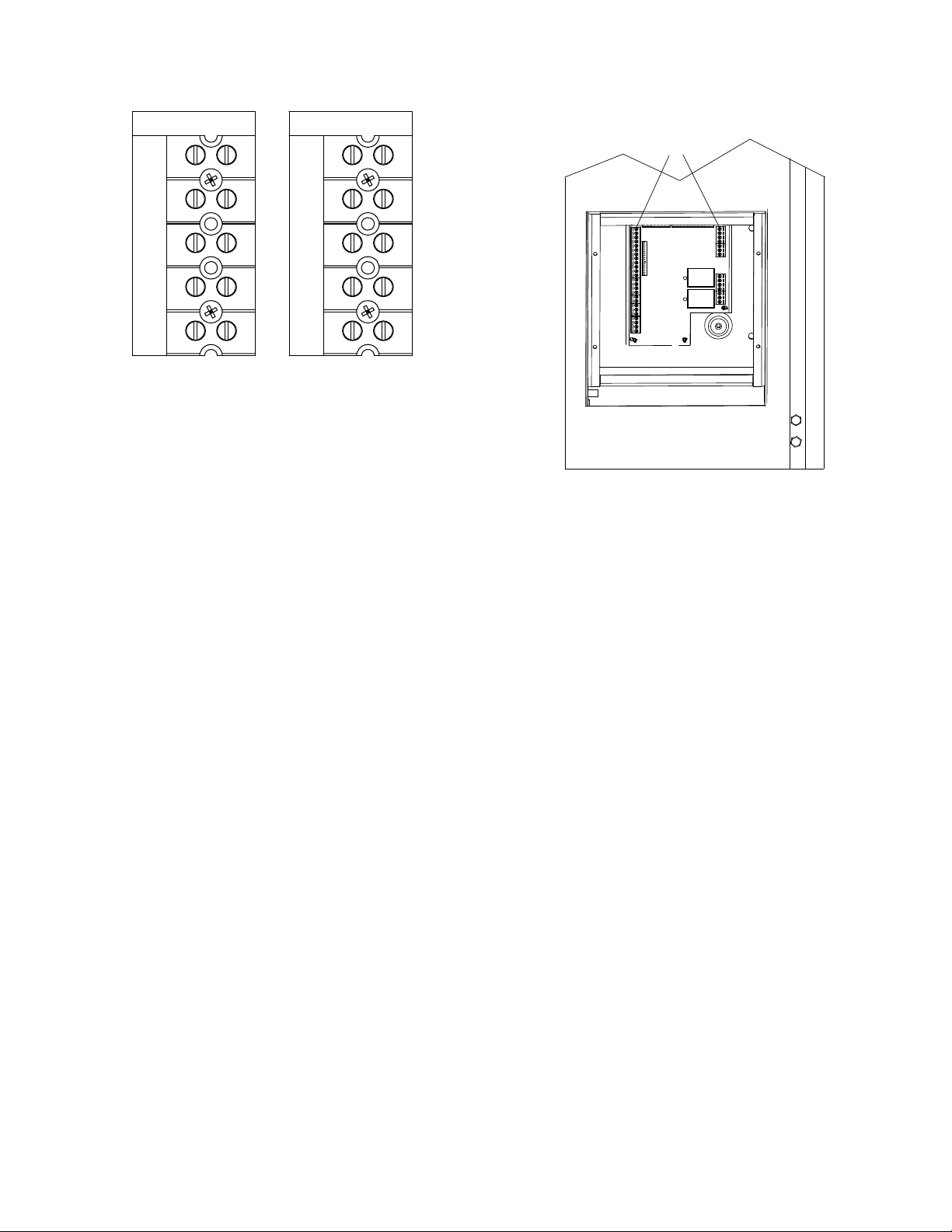
208 VAC, 3 PHASE
GND
NEU
460 VAC, 3 PHASE
GND
INSTALLATION
TERMINAL
STRIPS
L3
L2
L1
208 VAC, 3 Phase
L3
L2
L1
460 VAC, 3 Phase
Figure 2-9
AC Terminal Block Configurations
2.9 MODES OF OPERATION AND FIELD
CONTROL WIRING
The Benchmark 3.0 Boiler is available in several
different modes of operation. While each unit is
factory c onfigured an d wired f or its intend ed
mode, s ome addit ional f ield wir ing m ay be
required to c omplete the in stallation. This wiring
is t ypically c onnected t o t he I nput/Output ( I/O)
Box located on the lower portion of the unit front
panel ( Figure 2- 10) beh ind the r emovable f ront
door.
To a ccess t he I /O B ox t erminal st rips shown in
Figure 2-10, loosen t he f our c over s crews an d
remove the c over. A ll f ield wiring is ins talled
from the r ear of the pa nel b y r outing th e wires
through one of the four bushings provided.
LOWER RIGHT CORNER
OF FRONT PANEL
Figure 2-10.
Input/Output (I/O) Box Location
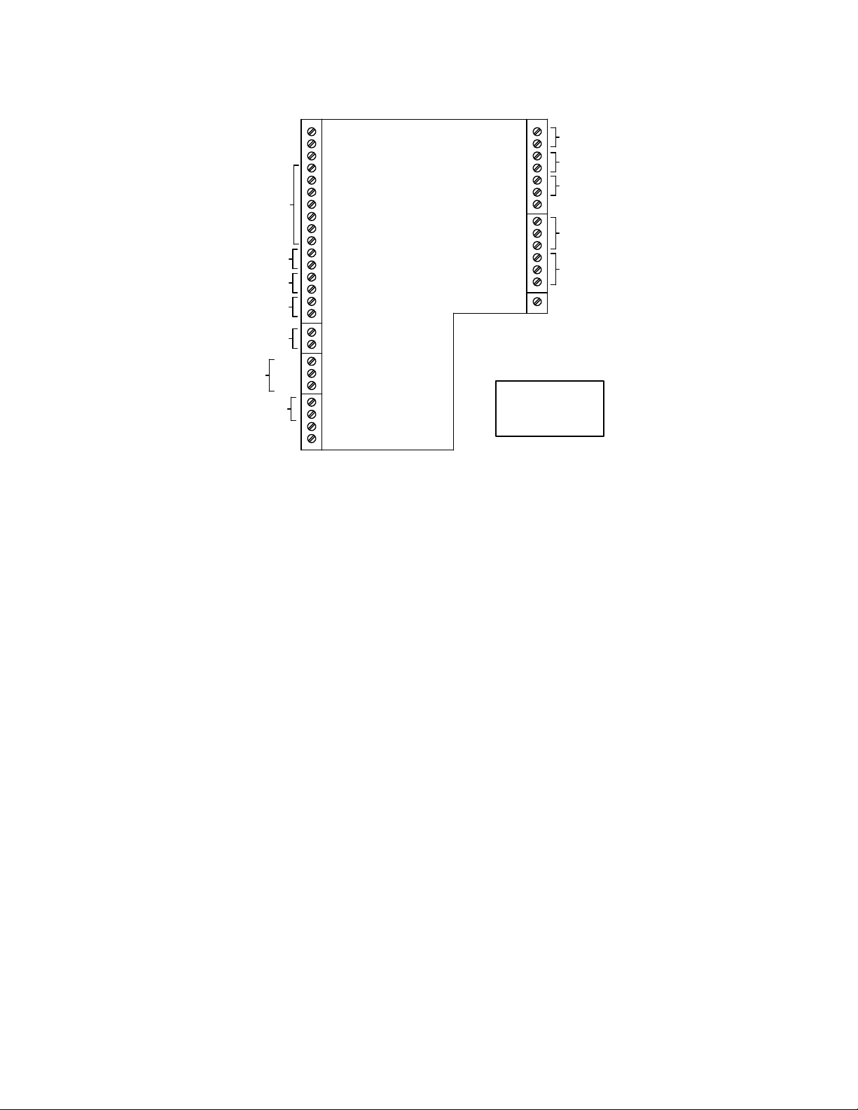
Refer to the wiring d iagram pr ovided on t he
cover of the I/O Box (Figure 2-11) when making
all wiring connections.
Brief des criptions of eac h mode of oper ation,
and the ir wiring r equirements, ar e pr ovided in
the f ollowing par agraphs. Additional information
concerning field wiring is provided in paragraphs
2.9.1 thr ough 2.9. 9. Ref er to Chapt er 5 f or
detailed i nformation on t he av ailable m odes of
operation
2-7
Page 20
INSTALLATION
OUTDOOR SENSOR IN
SENSOR COMMON
(AIR) AUX SENSOR IN
NOT USED
SHIELD
0 – 10V
AGND
+
+
-
+
-
+
G
-
ANALOG IN
B.M.S. (PWM) IN
mA OUT
RS-485
COMM.
NOT USED
Figure 2-11. I/O Box Terminal Strip
2.9.1 Constant Setpoint Mode
The Cons tant S etpoint M ode is us ed when it is
desired t o ha ve a f ixed s etpoint t hat d oes not
deviate. No w iring connections, oth er than AC
electrical po wer c onnections, ar e r equired f or
this mode. Ho wever, if desired, fault monitoring
or enable/disable interlock wiring can be utilized
(see paragraphs 2.9.9.1 and 2.9.10).
2.9.2 Indoor/Outdoor Reset Mode
This mode of oper ation i ncreases s upply water
temperature as outdoor temperatures decrease.
An outside air temperature sensor (AERCO Part
No. 122790) is required. T he sensor MUST BE
wired to the I/O Box wiring terminals (see Figure
2-11). Ref er to par agraph 2.10.1 f or add itional
information on ou tside air tem perature s ensor
installation.
2.9.3 Boiler Management System Mode
NOTE
BMS Mo del 16 8 c an utilize eit her p ulse
width m odulation ( PWM) or R S485
Modbus s ignaling to t he Boiler. BMS II
Model 5R 5-384 c an u tilize onl y RS 485
signaling to the Boiler.
When us ing an AERCO Boi ler M anagement
System ( BMS), th e f ield wir ing is c onnected
between th e BM S P anel and e ach Bo iler’s I/O
Box ter minal s trip ( Figure 2- 11). T wisted
shielded pair wire f rom 18 to 22 A WG must be
utilized for the connections. The BMS Mode can
2-8
REMOTE INTL'K IN
EXHAUST SWITCH IN
DELAYED INTL'K IN
NOT USED
NC
FAULT RELAY
COM
120 VAC, 5A, RES
NO
NC
AUX RELAY
COM
NO
120 VAC, 5A, RES
NOT USED
RELAY CONTACTS:
120 VAC, 30 VDC
5 AMPS RESISTIVE
DANGER
120 VAC USED
IN THIS BOX
utilize e ither pu lse width modulation ( PWM)
signaling, or RS485 Modbus signaling. For PWM
signaling, c onnections a re m ade f rom the
AERCO B oiler M anagement System to th e
B.M.S. ( PWM) IN ter minals on t he I/O Box
terminal s trip. F or RS 485 Mo dus s ignaling,
connections ar e m ade f rom the BMS t o th e
RS485 COMM terminals on the I/O Box terminal
strip. Polarity must be m aintained and the shield
must be c onnected o nly at th e AERCO BMS.
The boiler end of the shield must be left floating.
For ad ditional i nstructions, r efer to C hapter 5,
paragraph 5.6 in this m anual. Also, refer t o GF108M ( BMS Mod el 1 68) and G F-124 ( BMS I I
Model 5R5-384), BMS -Operations Guides.
2.9.4 Remote Setpoint and Direct Drive
Modes
The Benc hmark 3.0 Boi ler c an ac cept s everal
types of s ignal f ormats f rom an E nergy
Management S ystem ( EMS), Building
Automation S ystem ( BAS) or oth er s ource, to
control e ither the s etpoint ( Remote Setpo int
Mode) or f iring r ate ( Direct Dr ive Mo de) of the
Boiler. These formats are:
• 4 to 20 mA/1 to 5 VDC
• 0 to 20 mA/0 to 5 VDC
• PWM – ( Pulse Width Modulated signal. Se e
para. 2.10.4)
• Network (RS485 Modbus. See para. 2.10.8)
Page 21

INSTALLATION
While it is pos sible to c ontrol a bo iler or boi lers
using one of the previously described modes of
operation, it m ay not be the m ethod best suited
for the appl ication. Prior to s electing o ne of
these m odes of oper ation, it is r ecommended
that y ou consult w ith y our local AER CO
representative or the f actory f or the m ode of
operation th at will work bes t with your
application. F or more inf ormation on wiring th e
4 to 20 mA / 1to 5VDC or the 0 to 20 mA / 0 to 5
VDC, see paragraph 2.9.3.
2.9.5 Combination Mode
NOTE
Only BMS M odel 16 8 c an be ut ilized f or
the Com bination Mode, n ot the B MS II
(Model 5R5-384).
With a Com bination Mode un it, f ield wiring is
between the unit’s I/O Box wiring t erminals, the
CCP (Combination Control Panel), and the BMS
Model 1 68 ( Boiler Ma nagement S ystem). The
wiring m ust be ac complished us ing t wistedshielded pair wire from 18 to 22 A WG. Polar ity
must be m aintained. For further instructions and
wiring di agrams, r efer to the G F-108 Bo iler
Management System O perations Guide and the
CCP-1 data sheet.
2.10 I/O BOX CONNECTIONS
The t ypes of input and output s ignals and
devices to be connected to the I/O Box terminals
shown in F igure 2- 11 a re des cribed i n t he
following paragraphs.
CAUTION
DO NOT make any connections to the
I/O Box t erminals labeled “ NOT
USED”. A ttempting to d o so ma y
cause equipment damage.
2.10.1 OUTDOOR SENSOR IN
An outdoor air temperature sensor (AERCO Part
No. 12 2790) will be r equired pr imarily f or th e
Indoor/Outdoor reset mode of oper ation. It c an
also be used with another mode if it is desired to
use th e o utdoor s ensor e nable/disable f eature.
This f eature a llows the b oiler to be enabled or
disabled based on the outdoor air temperature.
The f actory def ault f or th e out door s ensor is
DISABLED. T o enable the sensor and/or select
an en able/disable o utdoor temperature, s ee the
Configuration menu in Chapter 3.
The outdoor sensor may be wired up to 200 feet
from the boiler. It is connected to the OUTDOOR
SENSOR IN and SENSOR COMMON terminals
in the I/O Box (see Figures 2-10 and 2-11). Wire
the s ensor us ing a t wisted s hielded pair wire
from 18 to 22 A WG. There is no po larity t o
observe when ter minating th ese wires. T he
shield is to be c onnected only t o t he terminals
labeled SHIELD in t he I/O Box. The sensor end
of the shield must be left free and ungrounded.
When mounting th e s ensor, it m ust be loc ated
on t he N orth s ide of th e bu ilding where an
average outs ide air tem perature is ex pected.
The sensor must be shielded from direct sunlight
as wel l as impingement b y the e lements. If a
shield is us ed, it m ust allo w f or f ree air
circulation.
2.10.2 AIR SENSOR IN
The AIR S ENSOR IN is c onnected t o the AUX
SENSOR IN and SENSOR COMMON terminals
on the I /O boar d. T he AI R SEN SOR m easures
the tem perature of the air inp ut to t he Air/Fuel
Valve. T his te mperature r eading is one of the
components us ed t o c alculate t he r otational
speed of the bl ower us ed in the c ombustion
Calibration process (Chapter 4).
The AUX SENSOR IN terminals can be used to
add a n ad ditional temperature s ensor f or
monitoring pur poses. T his in put is always
enabled a nd is a view-only input th at c an be
seen i n th e O perating M enu. T he s ensor m ust
be wired to the AUX SENSOR IN and SENSOR
COMMON t erminals a nd m ust be s imilar to
AERCO BALCO wire sensor Part No. 12449. A
resistance c hart f or this s ensor is pr ovided in
Appendix C.
2.10.3 ANALOG IN
The ANALO G IN + and – ter minals ar e us ed
when an ex ternal s ignal i s us ed t o dr ive t he
firing r ate ( Direct Dr ive Mode) or c hange th e
setpoint (Remote Setpoint Mode) of the Boiler.
Either a 4 to 20 mA /1 to 5 VDC or a 0 to 20 mA
/ 0 to 5 VDC s ignal m ay be us ed to vary t he
setpoint or firing rate. The factory default setting
is for 4 to 20 mA / 1 to 5 V DC, however this may
be changed to 0 to 20 mA / 0 to 5 VDC using the
Configuration Me nu des cribed i n Cha pter 3. If
voltage r ather t han c urrent is s elected as t he
drive s ignal, a DI P s witch must be s et on t he
PMC Board l ocated i nside th e Co ntrol B ox.
Contact the A ERCO f actory f or inf ormation o n
setting DIP switches.
All of the s upplied s ignals must be floating
(ungrounded) signals. Connections between the
signal s ource and the B oiler’s I/O Box must be
made using twisted shielded pair wire from 18 to
2-9
Page 22

INSTALLATION
22 AWG, s uch as Bel den 9 841 ( see
Figure 2-11). Polarity must be m aintained. T he
shield must be connected only at the source end
and m ust be left f loating ( not c onnected) at the
Boiler’s I/O Box.
Regardless of whether voltage or current is used
for the dr ive signal, they are linearly m apped to
a 40°F to 240°F setpoint or a 0% to 100% f iring
rate. No scaling for these signals is provided
2.10.4 B.M.S. (PWM) IN
NOTE
Only BMS Mod el 1 68 c an uti lize P ulse
Width Modulation (PWM), not th e B MS II
(Model 5R5-384).
These ter minals ar e used t o c onnect t he
AERCO Boi ler Ma nagement S ystem ( BMS)
Model 16 8 to the un it. T he BMS Mod el 1 68
utilizes a 12 m illisecond, ON/OFF dut y c ycle.
This duty cycle is Pulse Width Modulated (PWM)
to control firing rate. A 0% firing rate = a 5% ON
pulse and a 100% firing rate = a 95% ON pulse.
2.10.5 SHIELD
The SHIELD terminals are used to terminate any
shields us ed on s ensor wires c onnected to t he
unit. O nly s hields m ust be c onnected t o th ese
terminals.
IMPORTANT
DO NO T USE the m A OUT output to
remotely monitor Setpoint, Outlet Temp or
Fire Rate Out.
2.10.9 EXHAUST SWITCH IN
These ter minals per mit an ex ternal ex haust
switch to be c onnected to the ex haust m anifold
of the bo iler. T he ex haust s witch s hould be a
normally open type switch (such as AERCO Part
No. 123463) that closes (trips) at 500°F.
2.10.10 INTERLOCKS
The unit offers tw o i nterlock c ircuits f or
interfacing with En ergy M anagement Systems
and a uxiliary eq uipment s uch as pum ps or
louvers. These interlocks are called the Remote
Interlock and Dela yed I nterlock ( Figure 2- 11).
The w iring ter minals f or these int erlocks ar e
located i nside th e I/O Box on t he u nit f ront
panel. T he I/O Box c over c ontains a wiring
diagram which shows the terminal strip locations
for thes e inter locks ( REMOTE IN TL’K IN and
DELAYED INT L’K IN). Both interlocks,
described below, are factory wired in the c losed
position.
IMPORTANT
Both th e Rem ote In terlock and Del ayed
Interlock MUST be in the c losed pos ition
to allow the unit to fire.
2.10.10.1 REMOTE INTERLOCK IN
The r emote inter lock c ircuit is pr ovided to
remotely s tart ( enable) an d s top ( disable) th e
Boiler, if des ired. T he c ircuit is labe led
REMOTE INTL’K IN and is located inside the I/O
Box on t he f ront pan el. T he c ircuit is 24 V AC
and is factory pre-wired in the closed (jumpered)
position.
2.10.6 mA OUT
These terminals provide a 4 to 20 m A output to
the VFD (if so equipped) to control the rotational
speed of the blower. This function is enabled in
the Configuration Menu (Chapter 3, Table 3-4).
2.10.7 0 – 10V OUT
These ter minals pr ovide a 0 to 10V o utput to
control t he r otational s peed of the b lower. T his
function is e nabled i n t he Conf iguration Me nu
(Chapter 3, Table 3-4).
2.10.8 RS-485 COMM
These terminals are used for RS-485 MODBUS
serial c ommunication be tween the u nit a nd an
external “Master” such as a Boiler Management
System ( BMS), En ergy Management S ystem
(EMS), Building Automation S ystem ( BAS) or
other suitable device.
2-10
2.10.10.2 DELAYED INT ER LOCK IN
The del ayed interlock is t ypically used i n
conjunction with t he aux iliary r elay described in
paragraph 2. 10. T his inter lock c ircuit is loc ated
in the purge section of the start string. It c an be
connected to t he proving dev ice ( end s witch,
flow s witch etc .) of an aux iliary p iece of
equipment started by the Boiler’s auxiliary relay.
The dela yed i nterlock must be c losed f or the
boiler to fire.
If the delayed interlock is connected to a proving
device that requires time to close (make), a time
delay ( Aux Start O n D ly) that ho lds t he s tart
sequence of the boiler long enough for a proving
switch to make can be programmed. Should the
proving switch not prove within the programmed
time fr ame, the bo iler wi ll shut do wn. T he Aux
Start On Dly c an be programmed from 0 to 120
seconds. T his option is l ocate i n t he
Configuration Menu (Chapter 3, Table 3-4).
Page 23

INSTALLATION
2.10.11 FAULT RELAY
The f ault r elay is a s ingle pol e do uble thr ow
(SPDT) relay ha ving a normally op en and
normally c losed s et of r elay c ontacts that ar e
rated for 5 am ps at 12 0 VAC and 5 amps at 30
VDC. T he r elay e nergizes whe n an y f ault
condition occurs and remains energized until the
fault is c leared an d th e CLE AR button is
depressed. T he f ault r elay c onnections ar e
shown in Figure 2-11.
2.11 AUXILIARY RELAY CONTACTS
Each Bo iler is equ ipped w ith a s ingle po le
double t hrow ( SPDT) r elay th at is ener gized
when th ere is a dem and f or heat and deenergized after the d emand for heat is satisfied.
The relay is provided for t he control of auxiliary
equipment, such as p umps and l ouvers, or c an
be us ed as a Boiler status indictor (firing or not
firing). Its contacts ar e rated for 120 VAC @ 5
amps. Ref er to F igure 2- 11 t o l ocate the AUX
RELAY terminals for wiring connections.
2.12 FLUE GAS VENT INSTAL LATION
The minimum allo wable vent diam eter f or a
single Benchmark 3.0 Boiler is 8 inches.
The AERCO Benchmark Ventin g a nd
Combustion Air G uide, GF-2050, m ust be
consulted bef ore an y f lue gas ven t or in let air
venting is des igned or i nstalled. U/ L l isted,
positive pr essure, watertight v ent m aterials as
specified in AERCO’s G F-2050, m ust be us ed
for safety and code compliance. Since the unit is
capable of discharging low temperature exhaust
gases, h orizontal s ections of the f lue vent
system must be pitc hed bac k to the unit a
minimum of 1/4 inc h per f oot to avoid
condensate po oling a nd allo w f or pr oper
drainage.
The c ombined pr essure dr op of ve nt a nd
combustion air s ystems must not ex ceed 1 40
equivalent feet of 8 inch ducting. Fittings as well
as pipe lengths must be calculated as part of the
equivalent length.
For a n atural draft installation the draft must not
exceed ± 0.25 inch W.C. These factors must be
planned i nto t he vent ins tallation. If the
maximum allowable e quivalent lengths of piping
are ex ceeded, the unit will not oper ate pr operly
or reliably.
For Mas sachusetts boiler ins tallations, t he
Heatfab D ivision of the Se lkirk Cor poration
provides vent s ystems whic h c onform to all
applicable r equirements for ins tallations within
the C ommonwealth of Ma ssachusetts. Con tact
information for this supplier is as follows:
Selkirk Corporation
Heatfab Division
130 Industrial Blvd.
Turners Falls, MA 01376
Phone: 1-800-772-0739
www.heat-fab.com
2.13 COMBUSTION AIR
The AERCO Be nchmark Venting and C ombustion Air G uide, G F-2050 MUST be c onsulted
before any flue or combustion supply air venting
is des igned or im plemented. C ombustion a ir
supply is a d irect r equirement of ANSI 22 3.1,
NFPA-54, and local codes. These codes should
be c onsulted bef ore a p ermanent des ign is
determined.
The c ombustion a ir m ust be f ree of c hlorine,
halogenated h ydrocarbons, or other c hemicals
that c an become hazardous when used in gasfired eq uipment. Com mon s ources of t hese
compounds ar e s wimming poo ls, de greasing
compounds, plastic processing an d refrigerants.
Whenever the environment contains these types
of c hemicals, c ombustion air m ust be s upplied
from a c lean area out doors f or the pr otection
and longevity of the equipment.
The AER CO Benchmark 3.0 Boiler is U L listed
for 100% s ealed c ombustion. It c an als o be
installed us ing r oom air , provided ther e is an
adequate s upply. ( See p aragraph 2.1 3.3 f or
more information concerning sealed combustion
air). If the s ealed c ombustion air op tion is no t
being used, an in let s creen will b e at tached at
the air inlet on the top of the unit
The more c ommon methods of s upplying
combustion air are o utlined b elow. F or m ore
information c oncerning c ombustion air , c onsult
the AERCO B enchmark Ventin g an d
Combustion Air Guide, GF-2050.
2.13.1 Combustion Air From Outside the
Building
Air s upplied f rom outs ide the building m ust be
provided through two permanent openings. Each
opening m ust have a free area of not l ess than
one s quare i nch f or eac h 4000 BTU/H bo iler
input. T he f ree ar ea m ust tak e into ac count
restrictions such as louvers and bird screens.
2-11
Page 24

INSTALLATION
2.13.2 Combustion Air From Inside the
Building
When combustion air is provided from within the
building, it m ust be s upplied thr ough t wo
permanent op enings i n a n int erior wall. Each
opening m ust have a free area of not l ess than
one s quare inc h per 10 00 BTU/H of tota l b oiler
input. The free area must tak e into ac count any
restrictions such as louvers.
2.13.3 Sealed Combustion
The AER CO Benchmark 3.0 Boiler is U L listed
for 100%- sealed c ombustion. F or s ealed
combustion ins tallations, t he s creen on the a ir
inlet duct of the u nit must be removed. The inlet
air duc twork must then be attac hed dir ectly t o
the unit’s air inlet.
In a s ealed c ombustion air app lication, the
combustion air ducting pressure losses must be
taken into ac count when c alculating th e tota l
maximum allo wable v enting r un. See t he
AERCO Be nchmark Venti ng an d Com bustion
Air Guide, GF-2050. When using the boiler in a
sealed c ombustion a ir c onfiguration, each unit
must have a m inimum 8- inch diam eter
connection at the unit.
2.13.4 Temporary Combustion Air
Filtering During Construction
When the AERCO Benchmark 3.0 Boiler is used
to pr ovide he at tem porarily dur ing ongoing
building construction, accumulated drywall dust,
sawdust and similar particles can accumulate in
the un it’s c ombustion a ir i ntake f ilter and b lock
combustion air flow. In th ese situations, AERCO
recommends that a disposable air intake filter be
installed, temporarily, abo ve the bo iler
combustion air inlet.
AERCO recommends that the temporary air filter
be cut from a McMaster-Carr part no. 2 122K315
Polyester Air Filter Rol l Tackfield, 1/2” thick, 16”
wide, or e quivalent. C over the Benchmark 3.0
air in let with the b lue s ide of the f ilter m aterial
facing out ward to hold th e dus t on t he o utside
surface. Max imize th e s urface ar ea of the f ilter
covering the 8 " diameter opening b y c reating a
dome out of the filter material.
During c onstruction, c heck the f ilter f or dus t
accumulation a nd r eplace it when t he
accumulation becomes noticeable.
2-12
Page 25
CONTROL PANEL OPERATING PROCEDURES
CHAPTER 3 CONTROL PANEL OPERATING PROCEDURES
3.1 INTRODUCTION
The information in this Chapter provides a guide
to the operation of the Benchmark 3.0 Boiler
using the Control Panel mounted on the front of
the unit. It is imperative that the initial startup of
this unit be performed by factory trained
personnel. Operation prior to initial startup by
factory trained personnel will void the equipment
warranty. In addition, the following WARNINGS
and CAUTIONS must be observed at all times.
2
CAUTION
All of the installation procedures in
Chapter 2 must be completed before
attempting to start the unit.
WARNING
ELECTRICAL VOLTAGES IN THIS
SYSTEM MAY INCLUDE 460, 208
AND 24 VOLTS AC. IT MUST BE
SERVICED ONLY BY FACTORY
CERTIFIED SERVICE TECHNICIANS
WARNING
DO NOT ATTEMPT TO DRY FIRE
THE BOILER. STARTING THE UNIT
WITHOUT A FULL WATER LEVEL
CAN SERIOUSLY DAMAGE THE
UNIT AND MAY RESULT IN INJURY
TO PERSONNEL OR PROPERTY
DAMAGE. THIS SITUATION WILL
VOID ANY WARRANTY.
12
11
10
9
1
3
4
5
6
7
8
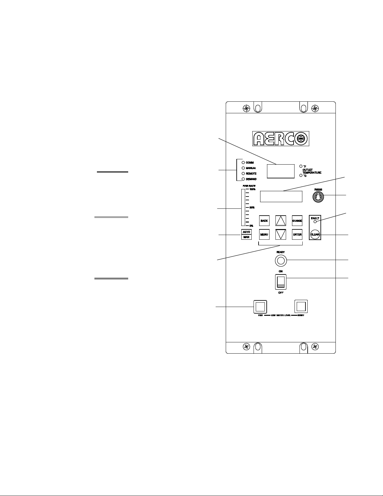
3.2 CONTROL PANEL DESCRIPTION
The Benchmark 3.0 Control Panel shown in
Figure 3-1 contains all of the controls, indicators
and displays necessary to operate, adjust and
troubleshoot the Benchmark 3.0 Boiler. These
operating controls, indicators and displays are
listed and described in Table 3-1. Additional
information on these items are provided in the
individual operating procedures provided in this
Chapter.
Figure 3-1.
Control Panel Front View
3-1
Page 26

CONTROL PANEL OPERATING PROCEDURES
Table 3-1 Operating Controls, Indicators and Displays
ITEM
NO.
CONTROL, INDICATOR
OR DISPLAY
1 LED Status Indicators Four Status LEDs indicate the current operating status as
follows:
COMM
MANUAL
REMOTE
DEMAND
OUTLET
2
TEMPERATURE
Display
3 VFD Display Vacuum Fluorescent Display (VFD) consists of 2 lines each
Lights when RS-232 communication is occurring
Lights when the unit is being controlled using the front panel
keypad.
Lights when the unit is being controlled by an external signal
from an Energy Management System
Lights when there is a demand for heat.
3–Digit, 7–Segment LED display continuously displays the
outlet water temperature. The °F or °C LED next to the
display lights to indicate whether the displayed temperature is
in degrees Fahrenheit or degrees Celsius. The °F or °C blinks
when operating in the Deadband Mode.
capable of displaying up to 16 alphanumeric characters. The
information displayed includes:
Startup Messages
Fault Messages
FUNCTION
Operating Status Messages
Menu Selection
RS-232 Port
4
FAULT Indicator Red FAULT LED indicator lights when a boiler alarm
5
CLEAR Key Turns off the FAULT indicator and clears the alarm message
6
READY Indicator
7
ON/OFF Switch
8
LOW WATER LEVEL
9
TEST/RESET Switches
Port permits a Laptop Computer or External Modem to be
connected to the unit’s Control Panel.
condition occurs. An alarm message will appear in the VFD.
if the alarm is no longer valid. Lockout type alarms will be
latched and cannot be cleared by simply pressing this key.
Troubleshooting may be required to clear these types of
alarms.
Lights ON/OFF switch is set to ON and all Pre-Purge
conditions have been satisfied.
Enables and disables boiler operation.
Allows operator to test operation of the water level monitor.
Pressing TEST opens the water level probe circuit and
simulates a Low Water Level alarm.
Pressing RESET resets the water level monitor circuit.
Pressing the CLEAR key (item 6) resets the display.
3-2
Page 27

CONTROL PANEL OPERATING PROCEDURES
Table 3-1 Operating Controls, Indicators and Displays – Continued
ITEM
NO.
10 MENU Keypad Consists of 6 keys which provide the following functions for
CONTROL, INDICATOR
OR DISPLAY
the Control Panel Menus:
MENU
BACK
▲ (UP) Arrow When in one of the main menu categories (Figure 3-2),
▼ (DOWN) Arrow When in one of the main menu categories (Figure 3-2),
CHANGE
Steps through the main menu categories shown in Figure 3-
2. The Menu categories wrap around in the order shown.
Allows you to go back to the previous menu level without
changing any information. Continuously pressing this key
will bring you back to the default status display in the VFD.
Also, this key allows you to go back to the top of a main
menu category.
pressing the ▲ arrow key will select the displayed menu
category. If the CHANGE key was pressed and the menu
item is flashing, pressing the ▲ arrow key will increment the
selected setting.
pressing this key will select the displayed menu category. If
the CHANGE key was pressed and the menu item is
flashing, pressing the ▼ arrow key will decrement the
selected setting.
Permits a setting to be changed (edited). When the
CHANGE key is pressed, the displayed menu item will begin
to flash. Pressing the ▲ or ▼ arrow key when the item is
flashing will increment or decrement the displayed setting.
FUNCTION
11
12
ENTER
AUTO/MAN Switch
VALVE POSITION
Bargraph
Saves the modified menu settings in memory. The display
will stop flashing.
This switch toggles the boiler between the Automatic and
Manual modes of operation. When in the Manual (MAN)
mode, the front panel controls are enabled and the
MANUAL status LED lights.
When in the Automatic (AUTO) mode, the MANUAL status
LED will be off and the front panel controls disabled.
20 segment red LED bargraph continuously shows the
Air/Fuel Valve position in 5% increments from 0 to 100%
3-3
Page 28
CONTROL PANEL OPERATING PROCEDURES
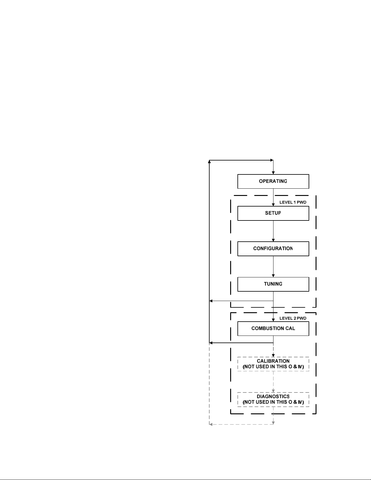
3.3 CONTROL PANEL MENUS
The Control Panel incorporates an extensive
menu structure which permits the operator to set
up, and configure the unit. The menu structure
consists of five major menu categories which are
applicable to this manual. These categories are
shown in Figure 3-2. Each of the menus shown,
contain options which permit operating
parameters to be viewed or changed. The
menus are protected by a password levels to
prevent unauthorized use.
Prior to entering the correct password, the
options contained in the Operation, Setup,
Configuration and Tuning Menu categories can
be viewed. However, with the exception of
Internal Setpoint Temperature (Configuration
Menu), none of the viewable menu options can
be changed.
Once the valid level 1 password (159) is
entered, the options listed in the Setup.
Configuration and Tuning Menus can be viewed
and changed, if desired. The Combustion Cal
Menu is protected by the level 2 password which
is used in Chapter 4 to perform combustion
calibration prior to service use.
available menu options in the Top-Down
sequence. Pressing the ▼ arrow key will
display the options in the Bottom-Up
sequence. The menu options will wraparound after the first or last available option
is reached.
6. To change the value or setting of a
displayed menu option, press the CHANGE
key. The displayed option will begin to flash.
Press the ▲ or ▼ arrow key to scroll
through the available menu option choices
for the option to be changed. The menu
option choices do not wrap around.
7. To select and store a changed menu item,
press the ENTER key.
3.3.1 Menu Processing Procedure
Accessing and initiating each menu and option
is accomplished using the Menu Keys shown in
Figure 3-1. Therefore, it is imperative that you
be thoroughly familiar with the following basic
steps before attempting to perform specific
menu procedures.
1. The Control Panel will normally be in the
Operating Menu and the VFD will display the
current unit status. Pressing the ▲ or ▼
arrow key will display the other available
data items in the Operating Menu.
2. Press the MENU key. The display will show
the Setup Menu, which is the next menu
category shown in Figure 3-2. This menu
contains the Password option which must be
entered if other menu options will be
changed.
3. Continue pressing the MENU key until the
desired menu is displayed.
4. With the desired menu displayed, press the
▲ or ▼ arrow key. The first option in the
selected menu will be displayed.
5. Continue to press the ▲ or ▼ arrow key
until the desired menu option is displayed.
Pressing the ▲ arrow key will display the
3-4
Figure 3-2. Menu Structure
Page 29

CONTROL PANEL OPERATING PROCEDURES
NOTE
The following paragraphs provide brief
descriptions of the options contained in each
menu. Refer to Appendix A for detailed
descriptions of each menu option. Refer to
Appendix B for listings and descriptions of
displayed startup, status and error
messages.
3.4 OPERATING MENU
The Operating Menu displays a number of key
operating parameters for the unit as listed in
Table 3-2. This menu is “Read-Only” and does
not allow personnel to change or adjust any
displayed items. Since this menu is “Read-Only”,
it can be viewed at any time without entering a
password. Pressing the ▲ arrow key to display
the menu items in the order listed (Top-Down).
Pressing the ▼ arrow key will display the menu
items in reverse order (Bottom-Up).
3.5 SETUP MENU
The Setup Menu (Table 3-3) permits the
operator to enter the unit password (159) which
is required to change the menu options. To
prevent unauthorized use, the password will
time-out after 1 hour. Therefore, the correct
password must be reentered when required. In
addition to permitting password entries, the
Setup Menu is also used to enter date and time,
units of temperature measurements and entries
required for external communication and control
of the unit via the RS-232 port. A view-only
software version display is also provided to
indicate the current Control Box software
version.
NOTE
The Outdoor Temp display item shown with
an asterisk in Table 3-2 will not be displayed
unless the Outdoor Sensor function has
been enabled in the Configuration Menu
(Table 3-4).
Table 3-2. Operating Menu
Available Choices or Limits
Menu Item Display Minimum Maximum Default
Status Message
Active Setpoint 40°F 240°F
AIR Temp -70°F 245°F
Outdoor Temp* -70°F 130°F
Valve Position In 0% Max Valve
Position
Flame Strength 0% 100%
Run Cycles 0 999,999,999
Run Hours 0 999,999,999
Fault Log 0 9 0
3-5
Page 30

CONTROL PANEL OPERATING PROCEDURES
Table 3-3. Setup Menu
Available Choices or Limits
Menu Item Display Minimum Maximum Default
Passsword 0 9999 0
Language English English
Time 12:00 am 11:59 pm
Date 01/01/00 12/31/99
Unit of Temp Fahrenheit or Celsius Fahrenheit
Comm Address 0 127 0
Baud Rate 2400, 4800, 9600, 19.2K 9600
Software Ver 0.00 Ver 9.99
3.6 CONFIGURATION MENU
The Configuration Menu shown in Table 3-4
permits adjustment of the Internal Setpoint
(Setpt) temperature regardless of whether the
valid password has been entered. Setpt is
required for operation in the Constant Setpoint
mode. The remaining options in this menu
require the valid password to be entered, prior to
changing existing entries. This menu contains a
number of other configuration settings which
may or may not be displayed, depending on the
current operating mode setting.
Table 3-4. Configuration Menu
Available Choices or Limits
Menu Item Display Minimum Maximum Default
Internal Setpt Lo Temp Limit Hi Temp Limit 130°F
Unit Type KC Boiler, KC Boiler LN,
BMK Boiler, BMK Boiler LN,
BMK Boiler Dual, KC Water
Heater, KC Water Heater LN,
Water Heater 2010
Unit Size 0.5 MBTU, 1.0 MBTU
1.5 MBTU, 2.0 MBTU
3.0 MBTU, 3.5 MBTU
4.0 MBTU, 5.0 MBTU
Fuel Type Natural Gas, Propane Natural Gas
Boiler Mode Constant Setpoint,
Remote Setpoint,
Combination
Outdoor Reset
NOTE
The Configuration Menu settings shown in
Table 3-4 are Factory-Set in accordance
with the requirements specified for each
individual order. Therefore, under normal
operating conditions, no changes will be
required.
BMK Boiler
LN
1.0 MBTU
6.0 MBTU
Constant
Setpoint
Direct Drive
3-6
Page 31

CONTROL PANEL OPERATING PROCEDURES
Table 3-4. Configuration Menu - Continued
Available Choices or Limits
Menu Item Display Minimum Maximum Default
Remote Signal
(If Mode = Remote
Setpoint, Direct Drive
or Combination)
Bldg Ref Temp
(If Mode = Outdoor
Reset)
Reset Ratio
(If Mode = Outdoor
Reset)
Outdoor Sensor Enabled or Disabled Disabled
System Start Tmp
(If Outdoor Sensor =
Enabled)
Setpt Lo Limit 40°F Setpt Hi Limit 60°F
Setpt Hi Limit Setpt Lo Limit 220°F 200°F
Temp Hi Limit 40°F 240°F 210°F
Max Fire Rate 40% 100% 100%
Pump Delay Timer 0 min. 30 min. 0 min.
Aux Start On Dly 0 sec. 120 sec. 0 sec.
Failsafe Mode Shutdown or Constant Setpt Shutdown
4 – 20 mA/1 – 5V
0 -20 mA/0 – 5V
PWM Input (BMS)
Network
40°F 230°F 70°F
0.1 9.9 1.2
30°F 100°F 60°F
4 – 20 mA,
1-5V
*Analog Output
(See CAUTION at
end of Table 3-4 )
Low Fire Timer 2 sec. 600 sec. 2 sec.
Setpt Limiting Enabled or Disabled Disabled
Setpt Limit Band 0°F 10°F 5°F
Network Timeout 5 Sec 999 Sec 30 Sec
HI DB Setpt EN 0% 100% 30%
Demand Offsert 0 25 10
Deadband High 0 25 2
Deadband Low 0 25 2
*CAUTION:
1. DO NOT CHANGE the Analog Output Menu Item from its Default setting (Valve
Position 0-10V).
Off, Setpoint, Outlet Temp,
Valve Position 4-20 mA,
Valve Position 0-10V
*Valve
Position
0-10V
3-7
Page 32

CONTROL PANEL OPERATING PROCEDURES
3.7 TUNING MENU
The Tuning Menu items in Table 3-5 are Factory
set for each individual unit. Do not change
these menu entries unless specifically requested
to do so by Factory-Trained personnel.
3.8 COMBUSTION CAL MENU
The Combustion Cal (Calibration) Menu items in
Table 3-6 are used to vary the speed of the
unit’s blower motor based on air temperature
and air density at prescribed Air/Fuel Valve
Table 3-5. Tuning Menu
Available Choices or Limits
Menu Item Display Minimum Maximum Default
Prop Band 1°F 120°F 70°F
Integral Gain 0.00 2.00 1.00
Derivative Time 0.0 min 2.00 min 0.00 min
Reset Defaults? Yes, No, Are You Sure? No
Table 3-6. Combustion Cal Menu
positions (% open). This is accomplished by
providing a DC drive voltage to the motor which
adjusts the rotational speed of the blower to
maximize combustion efficiency and ensure the
unit conforms to the Nitrogen Oxide (NOx) and
Carbon Monoxide (CO) emissions specified in
Chapter 4. The firing rates (%) and default drive
voltages are listed in Table 3-6.
Available Choices or Limits
Menu Item Display Minimum Maximum Default
CAL Voltage 16% .25 8.20 1.80v
CAL Voltage 30% .25 8.20 3.20v
CAL Voltage 45% .25 8.20 3.70v
CAL Voltage 60% .25 8.20 3.80
CAL Voltage 80% .25 8.20 4.60
CAL Voltage 100% .25 8.20 6.00
SET Valve Position 0% 100% 0%
Blower Output Monitor Blower Output Voltage .00
3.9 START SEQUENCE
When the Control Box ON/OFF switch is set to
the ON position, it checks all pre-purge safety
switches to ensure they are closed. These
switches include:
• Safety Shut-Off Valve Proof of Closure
(POC) switch
• Low Water Level switch
• High Water Temperature switch
• High Gas Pressure switch
• Low Gas Pressure switch
• Blower Proof switch
If all of the above switches are closed, the
READY light above the ON/OFF switch will light
and the unit will be in the Standby mode.
When there is a demand for heat, the following
events will occur:
NOTE
If any of the Pre-Purge safety device
switches are open, the appropriate fault
message will be displayed. Also, the
appropriate fault messages will be displayed
throughout the start sequence, if the
required conditions are not observed.
3-8
Page 33

CONTROL PANEL OPERATING PROCEDURES
1. The DEMAND LED status indicator will light.
2. The unit checks to ensure that the Proof of
Closure (POC) switch in the downstream
Safety Shut-Off Valve (SSOV) is closed.
See Figure 3-3 for SSOV location.
Valve (Figure 3-6) will read between 25
and 35 to indicate that the valve is in
the low-fire position.
(b) The igniter relay is activated and
provides ignition spark.
(c) The gas Safety Shut-Off Valve (SSOV)
is energized (opened) allowing gas to
flow into the Air/Fuel Valve.
Figure 3-3.
SSOV Location
3. With all required safety device switches
closed, a purge cycle will be initiated and the
following events will occur:
(a) The Blower relay energizes and turns
on blower.
(b) The Air/Fuel Valve rotates to the full-
open purge position and closes purge
position switch. The dial on the Air/Fuel
Valve (Figure 3-4) will read 100 to
indicate that it is full-open (100%).
(c) The VALVE POSITION bargraph will
show 100%.
4. Next, the blower proof switch on the Air/Fuel
Valve (Figure 3-5) closes. The display will
show Purging and indicate the elapsed time
of the purge cycle in seconds. The normal
(default) time for the purge cycle is 7
seconds.
5. Upon completion of the purge cycle, the
Control Box initiates an ignition cycle and
the following events occur:
(a) The Air/Fuel Valve rotates to the low-
fire ignition position and closes the
ignition switch. The dial on the Air/Fuel
Figure 3-4.
Air/Fuel Valve In Purge Position
Figure 3-5.
Blower Proof Switch
3-9
Page 34

CONTROL PANEL OPERATING PROCEDURES
8. With the unit firing properly, it will be
controlled by the temperature controller
circuitry. The boiler’s VALVE POSITION will
be continuously displayed on the front panel
bargraph.
Once the demand for heat has been satisfied,
the Control Box will turn off the dual SSOV gas
valves. The blower relay will be deactivated and
the Air/Fuel Valve will be closed. Standby will
be displayed.
3.10 START/STOP LEVELS
The start and stop levels are the Air/Fuel Valve
positions (% open) that start and stop the unit,
based on load. These levels are Factory preset
as follows:
Figure 3-6.
Air/Fuel Valve In Ignition Position
to be detected. The igniter relay will be
turned off one second after flame is
detected.
7. After 2 seconds of continuous flame, Flame
Proven will be displayed and the flame
strength will be indicated. After 5 seconds,
the current date and time will be displayed in
place of the flame strength.
Table 3-7
Relationship Between Air/Fuel Valve Position and Energy Input
Air/Fuel Valve
Position (% Open)
0% 0 0
10% 0 0
14%
(Stop Level) 200,000
20% 287,000 10%
30% 486,000 16%
40% 802,000 27%
50% 1,180,000 39%
60% 1,720,000 57%
70% 2,300,000 77%
80% 2,550,000 85%
90% 2,720,000 91%
100% 3,000,000 100%
Energy Input
(BTU/HR)
Start Level: 20%
Stop Level: 14%
Normally, these settings should not require
adjustment. 6. Up to 7 seconds will be allowed for ignition
Note that the energy input of the boiler is not
linearly related to the Air/Fuel Valve position.
Refer to Table 3-7 for the relationship between
the boiler energy input and the Air/Fuel Valve
position (% open) for a unit running on Natural
Gas.
Boiler Energy Input
(% Of Full Capacity)
6.67%
3-10
Page 35

INITIAL START-UP
CHAPTER 4 INITIAL START-UP
4.1 INITIAL START-UP REQUIREMENTS
The requirements for the initial start-up of the
Benchmark 3.0 Boiler consists of the following:
• Complete installation
• Perform combustion calibration
• Set proper controls and limits
• Set up mode of operation (see Chapter 5)
• Test safety devices (see Chapter 6)
Installation should be fully completed before
performing initial start-up; and the start-up must
be complete prior to putting the unit into service.
Starting a unit without the proper piping, venting,
or electrical systems can be dangerous and may
void the product warranty. The following start-up
instructions should be followed precisely in order
to operate the unit safely and at a high thermal
efficiency, with low flue gas emissions.
Initial unit start-up is to be performed ONLY by
AERCO factory trained start-up and service
personnel. After following the steps in this
chapter, it will be necessary to perform the Mode
of Operation settings in Chapter 5, and the
Safety Device Testing procedures in Chapter 6
to complete the initial unit start-up.
An AERCO Gas Fired Startup Sheet, included
with each Benchmark Boiler, must be completed
for each unit for warranty validation and a copy
must be returned promptly to AERCO at:
AERCO International, Inc.
159 Paris Ave.
Northvale, NJ 07647
CAUTION
All applicable installation procedures
in Chapter 2 must be completed
before attempting to start the unit.
4.2 TOOLS AND INSTRUMENTATION
FOR COMBUSTION CALIBRATION
To properly perform combustion calibration, the
proper instruments and tools must be used and
correctly attached to the unit. The following
paragraphs outline the necessary tools and
instrumentation as well as their installation.
4.2.1 Required Tools & Instrumentation
The following tools and instrumentation are
necessary to perform combustion calibration of
the unit:
• Digital Combustion Analyzer: Oxygen
accuracy to ± 0.4%; Carbon Monoxide
(CO) and Nitrogen Oxide (NOx) resolution
to 1PPM.
• 16 inch W.C. manometer or equivalent
gauge and plastic tubing.
• 1/8 inch NPT-to-barbed fittings for use with
gas supply manometer or gauge.
• Small and large flat blade screwdrivers.
• Tube of silicone adhesive
4.2.2 Installing Gas Supply Manometer
The gas supply manometer is installed in the
gas train as follows:
1. Close the main manual gas supply shut-off
valve upstream of the unit.
WARNING
DO NOT ATTEMPT TO DRY FIRE
THE BOILER. STARTING THE UNIT
WITHOUT A FULL WATER LEVEL
CAN SERIOUSLY DAMAGE THE
UNIT AND MAY RESULT IN INJURY
TO PERSONNEL OR PROPERTY
DAMAGE. THIS SITUATION WILL
VOID ANY WARRANTY.
2. Remove the front door and left side panels
from the boiler to access the gas train
components.
3. Remove the 1/8 inch NPT pipe plug from the
leak detection ball valve on the downstream
side of the Safety Shut Off Valve (SSOV) as
shown in Figure 4-1.
4-1
Page 36

INITIAL START-UP
4. Install a NPT-to-barbed fitting into the
tapped plug port.
5. Attach one end of the plastic tubing to the
barbed fitting and the other end to the 16
inch W.C. manometer.
1/8" NPT PLUG
(INSTALL MANOMETER HERE)
LEAK DETECTION
HIGH GAS
PRESSURE
SWITCH
SSOV
BALL VALVE
TO
AIR/FUEL
VALVE
LOW GAS
PRESSURE
SWITCH
GAS
INLET
Figure 4-1.
1/8 Inch Gas Plug Location
Prepare the port for the combustion analyzer
probe as follows:
1. Remove the plug from the probe port on the
right side of the exhaust manifold.
left or
2. If necessary, adjust the stop on the
combustion analyzer probe so that it will
extend mid-way into the flue gas flow. DO
NOT install the probe at this time.
4.3 NATURAL GAS COMBUSTION
CALIBRATION
The Benchmark 3.0LN Boiler is combustion
calibrated at the factory prior to shipping.
However, recalibration as part of initial start-up
is necessary due to changes in the local altitude,
gas BTU content, gas supply piping and supply
regulators. Factory Test Data sheets are
shipped with each unit. These sheets must be
filled out and returned to AERCO for proper
Warranty Validation.
It is important to perform the following procedure
as outlined. This will keep readjustments to a
minimum and provide optimum performance.
1. Open the water supply and return valves to
the unit and ensure that the system pumps
are running.
2. Open the natural gas supply valve(s) to the
unit.
4.2.3 Accessing the Vent Probe Port
The unit contains NPT plugs on both the left and
right side of the exhaust manifold at the rear of
the unit as shown in Figure 4-2.
Figure 4-2
Analyzer Probe Hole Location
3. Set the control panel ON/OFF switch to the
OFF position.
4. Turn on external AC power to the unit. The
display will show LOSS OF POWER and the
time and date.
5. Set the unit to the Manual Mode by pressing
the AUTO/MAN key. A flashing Manual
Valve Position message will be displayed
showing the present air/fuel valve % open
position. Also, the MANUAL LED will light.
6. Adjust the air/fuel valve position to 0% by
pressing the ▼ arrow key.
7. Ensure that the leak detection ball valve
downstream of the SSOV is open.
8. Set the ON/OFF switch to the ON position.
9. Change the valve position to 29% using the
▲ arrow key. The unit should begin its start
sequence and fire.
4-2
Page 37

INITIAL START-UP
10. Next, verify that the gas pressure
downstream of the SSOV is 1.8” W.C. for
both FM and IRI gas trains. If gas pressure
adjustment is required, remove the brass
hex nut covering the SSOV gas pressure
adjustment screw (Figure 4-3). Make gas
pressure adjustments using a flat-tip
screwdriver to obtain 1.8” W.C.
Table 4-1
Combustion Oxygen Levels for a 100%
Open Air/Fuel Valve Position
Inlet Air
Temp
>100°F 4.8 % <100 ppm <30 ppm
90°F 5.0 % <100 ppm <30 ppm
80°F 5.2 % <100 ppm <30 ppm
<70°F 5.3 % <100 ppm <30 ppm
14. If necessary, adjust the iris air damper
shown in Figure 4-4 until the oxygen level is
within the range specified in Table 4-1.
15. Once the oxygen level is within the specified
range at 100%, decrease the valve position
to 70%.
Oxygen %
± 0.2
Carbon
Monoxide NOx
Figure 4-3
Regulator Adjustment Screw Location
11. Increase the valve open position to 100%
and verify that the gas pressure downstream
of the SSOV remains at 1.8” W.C. Readjust
pressure if necessary. -
12. With the valve position at 100%, insert the
combustion analyzer probe into the flue
probe opening and allow enough time for the
combustion analyzer to settle.
13. Compare the measured oxygen level to the
oxygen range for the inlet air temperature
shown in Table 4-1. Also, ensure that the
carbon monoxide (CO) and nitrogen oxide
(NOx) readings do not exceed the values
shown.
Figure 4-4
Iris Air Damper Location/Adjustment
4-3
Page 38

INITIAL START-UP
NOTE
The remaining combustion calibration steps are
performed using the Combustion Cal Menu
included in the C-More Control System. The
combustion calibration control functions will be
used to adjust the oxygen level (%) at air/fuel
valve positions of 80%, 60%, 45%, 30% and
16% as described in the following steps. These
steps assume that the inlet air temperature is
within the range of 50°F to 100°F.
16. Press the MENU Key on the front panel of
the C-MORE and access the Setup menu.
Enter password 6817 and then press the
ENTER key.
17. Press the MENU Key on the front panel of
the C-MORE until Combustion Cal Menu
appears on the C-More display.
18. Press the ▲ arrow key until SET Valve
Position appears on the C-MORE display.
19. Press the CHANGE key. SET Valve Position
will begin to flash.
20. Press the ▲ arrow key until the SET Valve
Position reads 70%. Press the ENTER key.
21. Next, press the
CAL Voltage 70% is displayed.
down (▼) arrow key until
22. Press the CHANGE key and observe that
CAL Voltage 70% is flashing.
23. The oxygen level at the 70% valve position
should be as shown below. Also, ensure that
the carbon monoxide (CO) and nitrogen
oxide (NOx) readings do not exceed the
values shown.
Combustion Oxygen Level at
70% Valve Position
Oxygen %
± 0.2
6.0 % <100 ppm <30 ppm
24. If the oxygen level is not within the specified
range, adjust the level using the ▲ and ▼
arrow keys. This will adjust the output
voltage to the blower motor as indicated on
the display. Pressing the ▲ arrow key
increases the oxygen level and pressing the
down ▼ arrow key decreases the oxygen
level.
25. Once the oxygen level is within the specified
range at 70%, press the ENTER key to store
the selected blower output voltage for the
70% valve position.
4-4
Carbon
Monoxide
NOx
NOTE
The remaining steps basically repeat the
procedures in steps 18 through 25 for air/fuel
valve positions of 50%, 40%, 30% and 14%
open. However, since oxygen levels vary, these
steps are repeated in their entirety. When
performing these steps, also ensure that the
carbon monoxide (CO) and nitrogen oxide (NOx)
readings do not exceed the values shown for
each valve position.
26. Press the ▲ arrow key until SET Valve
Position appears on the C-MORE display.
27. Press the CHANGE key. SET Valve Position
will begin to flash.
28. Press the ▼ arrow key until the SET Valve
Position reads 50% and then press the
ENTER key.
29. Press the
Voltage 50% is displayed.
down ▼ arrow key until CAL
30. Press the CHANGE key. CAL Voltage 50%
will begin to flash.
31. The oxygen level at the 50% Valve Position
should be as shown below. Also, ensure that
the carbon monoxide (CO) and nitrogen
oxide (NOx) readings do not exceed the
values shown.
Combustion Oxygen Level at
50% Valve Position
Oxygen %
± 0.2
7.0 % <50 ppm <20 ppm
32. If the oxygen level is not within the specified
range, adjust the level using the ▲ and ▼
arrow keys. This will adjust the output
voltage to the blower motor as indicated on
the display. Pressing the ▲ arrow key
increases the oxygen level and pressing the
▼ arrow key decreases the oxygen level.
33. Once the oxygen level is within the specified
range at 50%, press the ENTER key to store
the selected blower output voltage for the
50% Valve Position.
34. Press the ▲ arrow key until SET Valve
Position appears on the C-MORE display.
35. Press the CHANGE key. SET Valve Position
will begin to flash.
36. Press the ▼ arrow key until the SET Valve
Position reads 40%, then press the ENTER
key.
Carbon
Monoxide
NOx
Page 39

INITIAL START-UP
37. Press the
40% is displayed.
▼ arrow key until CAL Voltage
38. Press the CHANGE key. CAL Voltage 40%
will begin to flash.
39. The oxygen level at the 40% valve position
should be as shown below. Also, ensure that
the carbon monoxide (CO) and nitrogen
oxide (NOx) readings do not exceed the
values shown.
Combustion Oxygen Level at
40% Valve Position
Oxygen %
± 0.2
7.8 % <50 ppm <20 ppm
40. If the oxygen level is not within the specified
range, adjust the level using the ▲ and ▼
arrow keys. This will adjust the output
voltage to the blower motor as indicated on
the display. Pressing the ▲ arrow key
increases the oxygen level and pressing the
▼ arrow key decreases the oxygen level.
41. Once the oxygen level is within the specified
range at 40%, press the ENTER key to store
the selected blower output voltage for the
40% valve position.
42. Press the ▲ arrow key until SET Valve
Position appears on the C-MORE display.
43. Press the CHANGE key. SET Valve Position
will begin to flash.
44. Press the ▼ arrow key until the SET Valve
Position reads 30%, then press the ENTER
key.
45. Press the
▼ arrow key until CAL Voltage
30% is displayed.
46. Press the CHANGE key. CAL Voltage 30%
will begin to flash.
47. The oxygen level at the 30% Valve Position
should be as shown below. Also, ensure that
the carbon monoxide (CO) and nitrogen
oxide (NOx) readings do not exceed the
values shown.
Carbon
Monoxide
NOx
Combustion Oxygen Level at
30% Valve Position
Oxygen %
± 0.2
8.0 % <50 ppm <20 ppm
48. If the oxygen level is not within the specified
range, adjust the level using the ▲ and ▼
Carbon
Monoxide
NOx
arrow keys. This will adjust the output
voltage to the blower motor as indicated on
the display. Pressing the ▲ arrow key
increases the oxygen level and pressing the
▼ arrow key decreases the oxygen level.
49. Once the oxygen level is within the specified
range at 30%, press the ENTER key to store
the selected blower output voltage for the
30% valve position.
50. Press the ▲ arrow key until SET Valve
Position appears on the C-MORE display.
51. Press the CHANGE key. SET Valve Position
will begin to flash.
52. Press the ▼ arrow key until the SET Valve
Position reads 14%, then press the ENTER
key.
53. Press the
14% is displayed.
▼ arrow key until CAL Voltage
54. Press the CHANGE key. CAL Voltage 14%
will begin to flash.
55. The oxygen level at the 14% Valve Position
should be as shown below. Also, ensure that
the carbon monoxide (CO) and nitrogen
oxide (NOx) readings do not exceed the
values shown.
Combustion Oxygen Level at
14% Valve Position
Oxygen %
± 0.2
8.5 % <50 ppm <30 ppm
56. If the oxygen level is not within the specified
range, adjust the level using the ▲ and ▼
arrow keys. This will adjust the output
voltage to the blower motor as indicated on
the display. Pressing the ▲ arrow key
increases the oxygen level and pressing the
▼ arrow key decreases the oxygen level.
57. Once the oxygen level is within the specified
range at 14%, press the ENTER key to store
the selected blower output voltage for 14%
Valve Position.
Carbon
Monoxide
NOx
IMPORTANT
Repeat steps 18 through 57 until the
blower output voltage does not require
adjustment when sequencing from 70% to
14%.
58. This completes the natural gas combustion
calibration procedure.
4-5
Page 40

INITIAL START-UP
4.4 UNIT REASSEMBLY
Once the combustion calibration adjustments
are properly set, the unit can be reassembled for
service operation.
1. Set the ON/OFF switch in the OFF position.
2. Disconnect AC power from the unit.
3. Shut off the gas supply to the unit.
4. Remove the manometer and barbed fittings
and reinstall the NPT plug using a suitable
pipe thread compound.
5. Remove the combustion analyzer probe
from the vent hole. Replace the NPT plug in
the vent hole using a suitable pipe joint
compound.
6. Replace the unit’s side panels and front
door.
RESET button before the boiler can be
restarted. The automatic reset over-temperature
switch is adjustable and allows the boiler to
restart, once the temperature drops below its
temperature setting. Set the automatic overtemperature switch to the desired setting.
4.5 OVER-TEMPER ATURE LIMIT
SWITCHES
The unit contains both automatic and manual
reset over-temperature limit switches. These
switches are mounted on a plate attached to the
boiler shell as shown in Figure 4-6. The switches
can be accessed by removing the left side
panels of the unit. The manual reset switch is
not adjustable and is permanently fixed at
210°F. This switch will shut down and lock out
the boiler if the water temperature exceeds
210°F. Following an over-temperature condition,
it must be manually reset by pressing the
Over Temperature Limit Switch
Figure 4-6
Locations
4-6
Page 41

MODE OF OPERATION
CHAPTER 5 MODE OF OPERATION
5.1 INTRODUCTION
The boiler is capable of being operated in any
one of six different modes. The following
paragraphs in this Chapter provide descriptions
of each of these operating modes. Each boiler is
shipped from the factory tested and configured
for the ordered mode of operation. All
temperature related parameters are at their
factory default values which work well in most
applications. However, it may be necessary to
change certain parameters to customize the unit
to the system environment. A complete listing
and descriptions of the temperature related
parameters are included in Appendix A. Factory
defaults are listed in Appendix E. After reading
this chapter, parameters can be customized to
suit the needs of the specific application.
5.2 INDOOR/OUTDOOR RESET MODE
This mode of operation is based on outside air
temperatures. As the outside air temperature
decreases, the supply header temperature will
increase and vice versa. For this mode, it is
necessary to install an outside air sensor as well
as select a building reference temperature and a
reset ratio.
5.2.3 Outdoor Air Temperature Sensor
Installation
The outdoor air temperature sensor must be
mounted on the North side of the building in an
area where the average outside air temperature
is expected. The sensor must be shielded from
the sun's direct rays, as well as direct
impingement by the elements. If a cover or
shield is used, it must allow free air circulation.
The sensor may be mounted up to two hundred
feet from the unit. Sensor connections are
made at the Input/Output (I/O) Box on the front
of the boiler. Connections are made at the
terminals labeled OUTDOOR SENSOR IN and
SENSOR COMMON inside the I/O Box. Use
shielded 18 to 22 AWG wire for connections. A
wiring diagram is provided on the cover of the
I/O Box. Refer to Chapter 2, paragraph 2.9.1 for
additional wiring information.
5.2.4 Indoor/ Outdoor Startup
Startup in the Indoor/Outdoor Reset Mode is
accomplished as follows:
1. Refer to the Indoor/Outdoor reset ratio
charts in Appendix D.
5.2.1 Reset Ratio
Reset ratio is an adjustable number from 0.1 to
9.9. Once adjusted, the supply header
temperature will increase by that number for
each degree that the outside air temperature
decreases. For instance, if a reset ratio of 1.6 is
used, for each degree that outside air
temperature decreases the supply header
temperature will increase by 1.6 degrees.
5.2.2 Building Reference Temperature
This is a temperature from 40°F to 230°F. Once
selected, it is the temperature that the system
references to begin increasing its temperature.
For instance, if a reset ratio of 1.6 is used, and
we select a building reference temperature of
70°F, then at an outside temperature of 69°F,
the supply header temperature will increase by
1.6° to 71.6°F.
2. Choose the chart corresponding to the
desired Building Reference Temperature.
3. Go down the left column of the chart to the
coldest design outdoor air temperature
expected in your area.
NOTE
A design engineer typically provides
design outdoor air temperature and
header temperature data
supply
4. Once the design outdoor air temperature is
chosen, go across the chart to the desired
supply header temperature for the design
temperature chosen in step 3.
5. Next, go up that column to the Reset Ratio
row to find the corresponding reset ratio.
6. Access the Configuration Menu and scroll
through it until the display shows Bldg Ref
Temp. (Building Reference Temperature).
5-1
Page 42

MODE OF OPERATION
7. Press the CHANGE key. The display will
begin to flash.
8. Use the ▲ and ▼ arrow keys to select the
desired Building Reference Temperature.
9. Press ENTER to save any changes.
10. Next, scroll through the Configuration Menu
until the display shows Reset Ratio.
11. Press the CHANGE key. The display will
begin to flash.
12. Use the ▲ and ▼ arrow keys to select the
Reset Ratio determined in step 5.
13. Press ENTER to save the change.
Refer to paragraph 3.3 for detailed instructions
on menu changing.
5.3 CONSTANT SETPOINT MODE
The Constant Setpoint mode is used when a
fixed header temperature is desired. Common
uses of this mode of operation include water
source heat pump loops, and indirect heat
exchangers for potable hot water systems or
processes.
5.4 REMOTE SETPOINT MODES
The unit’s setpoint can be remotely controlled by
an Energy Management System (EMS) or
Building Automation System (BAS). The Remote
Setpoint can be driven by a current or voltage
signal within the following ranges:
4-20 mA/1-5 Vdc
0-20 mA/0-5 Vdc
The factory default setting for the Remote
Setpoint mode is 4 - 20 mA/1 - 5 Vdc. With this
setting, a 4 to 20 mA/1 to 5 Vdc signal, sent by
an EMS or BAS, is used to change the unit's
setpoint. The 4 mA/1V signal is equal to a 40°F
setpoint while a 20 mA /5V signal is equal to a
240°F setpoint. When a 0 to 20 mA/0 to 5 Vdc
signal is used, 0 mA is equal to a 40°F setpoint.
In addition to the current and voltage signals
described above, the Remote Setpoint mode
can also driven by a RS485 Modbus Network
signal from an EMS or BAS.
The Remote Setpoint modes of operation can be
used to drive single as well as multiple units.
No external sensors are required to operate in
this mode. While it is necessary to set the
desired setpoint temperature, it is not necessary
to change any other temperature-related
functions. The unit is factory preset with settings
that work well in most applications. Prior to
changing any temperature-related parameters,
other than the setpoint, it is suggested that an
AERCO representative be contacted. For
descriptions of temperature-related functions
and their factory defaults, see Appendices A and
E.
5.3.1 Setting the Setpoint
The setpoint temperature of the unit is
adjustable from 40°F to 240°F. To set the unit
for operation in the Constant Setpoint Mode, the
following menu settings must be made in the
Configuration Menu:
MENU OPTION SETTING
Boiler Mode Constant Setpoint
Internal Setpt Select desired setpoint
using ▲ and ▼ arrow
keys (40°F to 240°F)
NOTE
If a voltage, rather than current signal is
used to control the remote setpoint, a DIP
switch adjustment must be made on the
CPU Board located in the Control Panel
Assembly. Contact your local AERCO
representative for details.
In order to enable the Remote Setpoint Mode,
the following menu setting must be made in the
Configuration Menu:
MENU OPTION SETTING
Boiler Mode Remote Setpoint
Remote Signal 4-20mA/1-5V,
0-20mA/0-5V, or
Network
Refer to paragraph 3.3 for detailed instructions
on changing menu options.
Refer to paragraph 3.3 for detailed instructions
on changing menu options.
5-2
Page 43

MODE OF OPERATION
If the Network setting is selected for RS485
Modbus operation, a valid Comm Address must
be entered in the Setup Menu. Refer to Modbus
Communication Manual GF-114 for additional
information.
While it is possible to change the settings of
temperature related functions, the unit is factory
preset with settings that work well in most
applications. It is suggested that an AERCO
representative be contacted, prior to changing
any temperature related function settings. For
descriptions of temperature-related functions
and their factory defaults, refer to Appendices A
and E.
5.4.1 Remote Setpoint Field Wiring
The only wiring connections necessary for the
Remote Setpoint mode are connection of the
remote signal leads from the source to the unit’s
I/O Box. The I/O Box is located on the front
panel of the boiler. For either a 4-20mA/0-5V or
a 0-20mA/0-5V setting, the connections are
made at the ANALOG IN terminals in the I/O
Box. For a Network setting, the connections are
made at the RS-485 COMM terminals in the I/O
Box. The signal must be floating, (ungrounded)
at the I/O Box and the wire used must be a two
wire shielded pair from 18 to 22 AWG. Polarity
must be observed. The source end of the shield
must be connected at the source. When driving
multiple units, each unit’s wiring must conform to
the above.
5.4.2 Remote Setpoint Startup
Since this mode of operation is factory preset
and the setpoint is being externally controlled,
no startup instructions are necessary. In this
mode, the REMOTE LED will light when the
external signal is present.
To operate the unit in the Manual mode, press
the AUTO/MAN switch. The REMOTE LED will
go off and the MANUAL LED will light.
To change back to the Remote Setpoint mode,
simply press the AUTO/M AN switch. The
REMOTE LED will again light and the MANUAL
LED will go off.
5.5 DIRECT DRIVE MODES
The unit’s air/fuel valve position (% open) can be
changed by a remote signal which is typically
sent from an Energy Management System
(EMS) or from a Building Automation System
(BAS). The Direct Drive mode can be driven by
a current or voltage signal within the following
ranges:
4-20 mA/1-5 Vdc
0-20 mA/0-5 Vdc
The factory default setting for the Direct Drive
mode is 4-20 mA/1-5 Vdc. With this setting, a 4
to 20 mA signal, sent by an EMS or BAS is used
to change the unit’s valve position from 0% to
100%. A 4 mA/1V signal is equal to a 0% valve
position, while a 20 mA /5V signal is equal to a
100% valve position. When a 0-20 mA/0-5 Vdc
signal is used, zero is equal to a 0% valve
position.
In addition to the current and voltage signals
described above, the Direct Drive mode can also
driven by a RS485 Modbus Network signal from
an EMS or BAS.
When in a Direct Drive mode, the unit is a slave
to the EMS or BAS and does not have a role in
temperature control. Direct Drive can be used to
drive single, or multiple units.
NOTE
If a voltage, rather than current signal is
used to control the remote setpoint, a DIP
switch adjustment must be made on the
CPU Board located in the Control Box
Assembly. Contact your local AERCO
representative for details.
To enable the Direct Drive Mode, the following
menu setting must be made in the Configuration
Menu:
MENU OPTION SETTING
Boiler Mode Direct Drive
Remote Signal 4-20mA/1-5V,
0-20mA/0-5V, or
Network
Refer to paragraph 3.3 for instructions on
changing menu options.
5-3
Page 44

MODE OF OPERATION
If the Network setting is selected for RS485
Modbus operation, a valid Comm Address must
be entered in the Setup Menu. Refer to Modbus
Communication Manual GF-114 for additional
information.
5.5.1 Direct Drive Field Wiring
The only wiring connections necessary for Direct
Drive mode are connection of the remote signal
leads from the source to the unit’s I/O Box. For
either a 4-20mA/0-5V or a 0-20mA/0-5V setting,
the connections are made at the ANALOG IN
terminals in the I/O Box. For a Network setting,
the connections are made at the RS-485 COMM
terminals in the I/O Box. The signal must be
floating, (ungrounded) at the I/O Box and the
wire used must be a two wire shielded pair from
18 to 22 AWG. Polarity must be observed. The
source end of the shield must be connected at
the source. When driving multiple units, each
unit’s wiring must conform to the above.
5.5.2 Direct Drive Startup
Since this mode of operation is factory preset
and the valve position is being externally
controlled, no startup instructions are necessary.
In this mode, the REMOTE LED will light when
the signal is present.
To operate the unit in manual mode, press the
AUTO/MAN switch. The REMOTE LED will go
off and the MANUAL LED will light.
To change back to the Direct Drive mode, simply
press the AUTO/MAN switch. The REMOTE
LED will again light and the MANUAL LED will
go off.
5.6 BOILER MANAGEMENT SYSTEM
(BMS)
NOTE
BMS Model 168 can utilize either pulse
width modulation (PWM) or RS485
Modbus signaling to the Boiler. BMS II
Model 5R5-384 can utilize only RS485
signaling to the Boiler.
The BMS mode of operation is used in
conjunction with an AERCO Boiler Management
System. The BMS mode is used when it is
desired to operate multiple units in the most
efficient manner possible. For this mode of
operation, a BMS Header Sensor must be
installed between 2 and 10 feet downstream of
the LAST boiler in the boiler plant's supply water
header. The BMS can control up to 40 boilers; 8
via pulse width modulation (PWM) and up to 32
via Modbus (RS485) network communication.
For BMS programming, operation, and Header
Sensor installation details, see GF-108M (BMS
Model 168) and GF-124 (BMS II Model 5R5-
384), BMS Operations Guides. For operation via
an RS485 Modbus network, refer to Modbus
Communication Manual GF-114.
To enable the BMS Mode, the following menu
settings must be made in the Configuration
Menu:
MENU OPTION SETTING
Boiler Mode Direct Drive
Remote Signal BMS (PWM Input)
or
Network (RS485)
Refer to paragraph 3.3 for instructions on
changing menu options.
5.6.1 BMS External Field Wiring
Wiring connections for BMS control using PWM
signaling are made between connector JP2 on
the BMS panel (boilers 1 through 8), and the
B.M.S. (PWM) IN terminals in the I/O Box on the
front of the boilers. Refer to the wiring diagram
provided on the cover of the I/O Box.
Wiring connections for RS485 Modbus control
are made between connector JP11 on the BMS
(boilers 9 through 40) and the RS485 COMM
terminals in the I/O Box on the front of the
boilers.
Wire the units using shielded twisted pair wire
between 18 and 22 AWG. Observe the proper
polarity for the B.M.S. (PWM) IN and/or RS485
COMM wiring connections. Shields should be
terminated only at the BMS and the boiler end
must be left floating. Each unit’s wiring must
conform to the above.
5.6.2 BMS Setup and Startup
This mode of operation is factory preset and the
AERCO BMS controls the firing rate (air/fuel
valve % open position). There are no setup
instructions for each individual unit.
To operate the unit in manual mode, press the
AUTO/MAN switch. The REMOTE LED will go
off and the MANUAL LED will light
5-4
Page 45

MODE OF OPERATION
To change back to the BMS mode, simply press
the AUTO/MAN switch. The REMOTE LED will
again light and the MANUAL LED will go off.
5.7 COMBINATION CONTROL SYSTEM
(CCS)
NOTE
Only BMS Model 168 can be utilized for
the Combination Mode, not the BMS II
(Model 5R5-384).
A Combination Control System (CCS) is one
that uses multiple boilers to cover both spaceheating and domestic hot water needs. An
AERCO Boiler Management System (BMS)
Model 168 and a Combination Control Panel
(CCP) are necessary to configure this system.
Typically, an adequate number of boilers are
installed to cover the space-heating load on the
design day, however one or more units are used
for the domestic hot water load.
The theory behind this type of system is that the
maximum space-heating load and the maximum
domestic hot water load do not occur simultaneously.+ Therefore, boilers used for the
domestic hot water are capable of switching
between constant setpoint and BMS modes of
operation. These boilers are the combination
units and are referred to as the combo boilers.
The combo boilers heat water to a constant
setpoint temperature. That water is then
circulated through a heat exchanger in a
domestic hot water storage tank.
When the space-heating load is such that all the
space-heating boilers are at the 100% valve
position, the BMS will then ask the Combination
Control Panel for the domestic boilers to
become space-heating boilers. Provided the
domestic hot water load is satisfied, the combo
(hot water) boilers will then become spaceheating boilers. If the domestic hot water load is
not satisfied, the combo boiler(s) remain on the
domestic hot water load. If the combo boilers
switch over to space heating, but there is a call
for domestic hot water, the CCP switches the
combo units back to the domestic load.
When the combo units are satisfying the
domestic load they are in constant setpoint
mode of operation. When the combo units
switch over to space heating, their mode of
operation changes to the BMS mode. For more
information concerning the operation of the
Combination Control Panel see the AERCO
CCP-1 literature.
5.7.1 Combination Control System Field
Wiring
Wiring for this system is between the BMS
Model 168 panel, the CCP and the B.M.S.
(PWM) IN terminals in the I/O Box. Wire the
units using a shielded twisted pair of 18 to 22
AWG wire. When wiring multiple units, each
unit’s wiring must conform to the above. For a
complete CCP system-wiring diagram see the
AERCO CCP-1 literature.
5.7.2 Combination Control System Setup
and Startup
Setup for the Combination Mode requires entries
to be made in the Configuration Menu for boiler
mode, remote signal type and setpoint. The
setpoint is adjustable from 40°F to 240°F.
Enter the following settings in the Configuration
Menu:
MENU OPTION SETTING
Boiler Mode Combination
Remote Signal BMS (PWM Input)
Internal Setpt 40°F to 240°F
Refer to paragraph 3.3 for instructions on
changing menu options.
While it is possible to change other temperaturerelated functions for combination mode, thes
functions are preset to their factory default
values. These default settings work well in most
applications. It is suggested that AERCO be
contacted prior to changing settings other than
the unit’s setpoint. For a complete listing of
temperature related function defaults, see
Appendix E.
To set the unit to the manual mode, press the
AUTO/MAN switch. The MANUAL LED will
light.
To set the unit back to the auto mode, press the
AUTO/MAN switch. The MANUAL LED will go
off and the REMOTE LED will light.
When the boiler is switched to BMS mode, the
AERCO BMS controls the valve position. There
are no setup requirements to the boiler(s) in this
mode.
5-5
Page 46

Page 47

SAFETY DEVICE TESTING
1/8
G
CHAPTER 6 SAFETY DEVICE TESTING
6.1 TESTING OF SAFETY DEVICES
Periodic safety device testing is required to
ensure that the control system and safety
devices are operating properly. The Benchmark
3.0LN control system comprehensively monitors
all combustion-related safety devices before,
during and after the start sequence. The
following tests check to ensure that the system
is operating as designed.
Operating controls and safety devices should be
tested on a regular basis or following service or
replacement. All testing must conform to local
codes such as ASME CSD-1.
NOTE
MANUAL and AUTO modes of operation
are required to perform the following
tests. For a complete explanation of these
modes, see Chapter 3.
NOTE
It will be necessary to remove the front
door and side panels from the unit to
perform the following tests.
WARNING
ELECTRICAL VOLTAGES IN THIS
SYSTEM MAY INCLUDE 460, 220,
120 AND 24 VOLTS AC. POWER
MUST BE REMOVED PRIOR TO
PERFORMING WIRE REMOVAL OR
OTHER TEST PROCEDURES THAT
CAN RESULT IN ELECTRICAL
SHOCK.
6.2 LOW GAS PRESSURE FAULT TEST
Refer to Figure 6-1 and ensure that the leak
detection ball valve located at the high gas
pressure switch is closed.
1. Remove the 1/8 “ plug from the ball valve at
the low gas pressure switch shown in the
lower portion of Figure 6-1.
2. Install a 0 – 16 “ W.C. manometer or a W.C.
gauge where the 1/8" plug was removed.
3. Slowly open the ball valve near the low gas
pressure switch.
4. Place the unit in Manual Mode and adjust the
air/fuel valve position (% open) between 25
and 30%.
5. While the unit is firing, slowly
close the
external manual gas shut-off valve.
6. The unit should shut down and display a
LOW GAS PRESSURE fault message at
approximately 2.6” W.C. The FAULT indi-
cator should also start flashing.
(INSTALL MANOMETER HERE
FOR HIGH GAS PRESSURE
HIGH GAS
PRESSURE
SWITCH
SSOV
1/8" NPT PLUG
(INSTALL MANOMETER HERE
FOR LOW GAS PRESSURE
FAULT TEST)
" NPT PLU
FAULT TEST)
LEAK DETECTION
BALL VALVE
BALL VALVE
TO
AIR/FUEL
VALVE
LOW GAS
PRESSURE
SWITCH
GAS
INLET
Figure 6-1
Low & High Gas Pressure Testing
7. Fully open the external manual gas shut-off
valve and press the CLEAR button on the
Control Box.
8. The fault message should clear and the
FAULT indicator should go off. The unit
should restart.
9. Upon test completion, close the ball valve
and remove the manometer. Replace the 1/8
“ plug removed in step 1.
6-1
Page 48

SAFETY DEVICE TESTING
6.3 HIGH GAS PRESSURE TEST
To simulate a high gas pressure fault, refer to
Figure 6-1 and proceed as follows:
1. Remove the 1/8 “ plug from the leak
detection ball valve shown in the upper
portion of Figure 6-1.
2. Install a 0 – 16” W.C. manometer (or W.C.
gauge) where the 1/8” plug was removed.
3. Slowly open the leak detection ball valve
4. Start the unit in Manual mode at a valve
position (firing rate) between 25 and 30%.
5. Slowly increase the gas pressure using the
adjustment screw on the SSOV Actuator
(see Figure 4-3).
6. The unit should shut down and display a
HIGH GAS PRESSURE fault message
when the gas pressure exceeds 2.6” W.C.
The FAULT indicator should also start
flashing.
7. Reduce the gas pressure back to 1.8” W.C.
8. Press the CLEAR button on the Control Box
to clear the fault.
9. The fault message should clear and the
FAULT indicator should go off. The unit
should restart.
10. Upon test completion, close the ball valve
and remove the manometer. Replace the
1/8“ plug removed in step 1.
6.4 LOW WATER LEVEL FAUL T TEST
To simulate a low water level fault:
1. Set the ON/OFF switch to the OFF position
2. Close the water shut-off valves in the supply
and return piping to the unit.
3. Slowly open the drain valve on the rear of the
unit. If necessary the unit’s relief valve may
be opened to aid in draining.
4. Continue draining the unit until a LOW
WATER LEVEL fault message is displayed
and the FAULT indicator flashes.
6. Set the ON/OFF switch to the ON position.
The READY light should remain off and the
unit should not start. If the unit does start,
shut the unit off immediately and refer fault to
qualified service personnel.
7. Close the drain and pressure relief valve
used in draining the unit.
8. Open the water shut-off valve in the return
piping to the unit.
9. Open the water supply shut-off valve to the
unit to refill.
10. After the shell is full, press the LOW WATER
LEVEL RESET button to reset the low water
cutoff.
11. Press the CLEAR button to reset the FAULT
LED and clear the displayed error message.
12. Set the ON/OFF switch to the ON position.
The unit is now ready for operation.
6.5 WATER TEMPERATURE FAULT
TEST
A high water temperature fault is simulated by
adjusting the automatic over-temperature switch.
This switch is accessible from the left side of the
unit as shown in Figure 6-2.
1. Start the unit in the normal operating mode.
Allow the unit to stabilize at its setpoint.
Lower the adjustable over-temperature switch
setting to match the displayed OUTLET
TEMPERATURE.
Once the adjustable over-temperature switch
setting is approximately at, or just below, the
actual outlet water temperature, the unit
should shut down. The FAULT indicator
should start flashing and a HIGH WATER
TEMP SWITCH OPEN fault message should
be displayed. It should not be possible to
restart the unit.
Reset the adjustable over-temperature switch to
its original setting.
The unit should start once the adjustable
temperature limit switch setting is above the
actual outlet water temperature.
5. Place the unit in the Manual Mode and raise
the valve position above 30%.
6-2
Page 49

SAFETY DEVICE TESTING
RESET BUTTON FOR MANUAL
RESET TEMPERATURE LIMIT
SWITCH
HIGH LIMIT
ADJUSTABLE
TEMPERATURE
LIMIT SWITCH
MOUNTING
PLATE
ON SHELL
Figure 6-2
Temperature Limit Switch Setting
Once the adjustable over-temperature switch
setting is approximately at, or just below, the
actual outlet water temperature, the unit
should shut down. The FAULT indicator
should start flashing and a HIGH WATER
TEMP SWITCH OPEN fault message should
be displayed. It should not be possible to
restart the unit.
Reset the adjustable over-temperature switch to
its original setting.
The unit should start once the adjustable
temperature limit switch setting is above the
actual outlet water temperature.
6.6 INTERLOCK TESTS
The unit is equipped with two interlock circuits
called the Remote Interlock and Delayed
Interlock. Terminal connections for these circuits
are located in the I/O Box (Figure 2-9) and are
labeled REMOTE INTL’K IN and DELAYED
INTL’K IN. These circuits can shut down the
unit in the event that an interlock is opened.
These interlocks are shipped from the factory
jumpered (closed). However, each of these
interlocks may be utilized in the field as a remote
stop and start, an emergency cut-off, or to prove
that a device such as a pump, gas booster, or
louver is operational.
6.6.1 REMOTE INTERLOCK
1. Remove the cover from the I/O Box and
locate the REMOTE INTL’K IN terminals.
2. Start the unit in the Manual Mode and set the
valve position between 25% and 30%.
3. If there is a jumper across the REMOTE
INTL’K IN terminals, remove one side of the
jumper. If the interlock is being controlled by
an external device, either open the interlock
via the external device or disconnect one of
the wires leading to the external device.
4. The unit should shut down and display
INTERLOCK OPEN.
5. Once the interlock connection is
reconnected, the INTERLOCK OPEN
message should automatically clear and the
unit should restart.
6.6.2 DELAYED INTERLOCK
Remove the cover from the I/O Box and locate
the DELAYED INTL’K IN terminals.
Start the unit in the Manual Mode at a valve
position between 25% and 30%.
If there is a jumper across the DELAYED INTL’K
IN terminals, remove one side of the jumper. If
the interlock is connected to a proving switch of
an external device, disconnect one of the wires
leading to the proving switch.
The unit should shut down and display a
DELAYED INTERLOCK OPEN fault message.
The FAULT LED should be flashing.
Reconnect the wire or jumper removed in step 3
to restore the interlock.
Press the CLEAR button to reset the fault
The unit should start.
6.7 FLAME FAULT TESTS
Flame faults can occur during ignition or while
the unit is already running. To simulate each of
these fault conditions, proceed as follows:
1. Set the ON/OFF switch to the OFF position.
2. Place the unit in the Manual Mode and set
the valve position between 25% and 30%.
6-3
Page 50

SAFETY DEVICE TESTING
3. Close the manual gas shutoff valve located
between the Safety Shut-Off Valve (SSOV)
and the Air/Fuel Valve (see Figure 6-3).
AIR
INLET
BLOCKED
P/O FRAME
AIR/FUEL
VALVE
MANUAL GAS
SHUTOFF VALVE
GAS
INLET
HANDLE
PARTIAL LEFT SIDE VIEW
INLET
SWITCH
BLOWER PROOF
SWITCH
BLOWER
SSOV
Figure 6-3
Manual Gas Shut-Off Valve Location
4. Set the ON/OFF switch to the ON position to
start the unit.
5. The unit should shut down after reaching the
Ignition cycle and display FLAME LOSS
DURING IGN.
6. Open the valve previously closed in step 3
and press the CLEAR button.
7. Restart the unit and allow it to prove flame.
8. Once flame is proven, close the manual gas
valve located between the SSOV and the
Air/Fuel Valve.
The unit should shut down and execute an
IGNITION RETRY cycle by performing the
following steps:
(a) The unit will execute a shutdown purge
cycle for a period of 15 seconds and
display WAIT FAULT PURGE.
(b) The unit will execute a 30 second re-
ignition delay and display WAIT RETRY
PAUSE.
(c) The unit will then execute a standard
ignition sequence and display WAIT
IGNITION RETRY.
9. Open the valve previously closed in step 8.
10. Press the CLEAR button. The unit should
restart and fire.
6.8 AIR FLOW FAULT TESTS
These tests check the operation of the Blower
Proof Switch and Blocked Inlet Switch shown in
Figure 6-3.
1. Disable the blower output drive voltage as
follows:
(a) Press the MENU key until CONFIGUR-
ATION MENU is displayed.
(b) Press the ▲ arrow key until the ANA-
LOG OUTPUT function is displayed,
then press the CHANGE key.
(c) Press the ▼ arrow key until OFF is
displayed, then press the ENTER key.
2. Start the unit in the Manual Mode at a valve
position between 25% and 30%.
3. The unit should shut down and execute an
IGNITION RETRY cycle by performing the
following steps:
(a) The unit will execute a 30 second re-
ignition delay and display WAIT RETRY
PAUSE.
(b) The unit will then execute a standard
ignition sequence and display WAIT
IGNITION RETRY.
4. The unit should perform two IGNITION
RETRY cycles and then shut down on the
third successive ignition attempt. The unit will
display AIRFLOW FAULT DURING PURGE.
6-4
Page 51

SAFETY DEVICE TESTING
5. Re-enable the blower output drive voltage by
performing the following steps:
(a) Press the MENU key until CONFIGUR-
ATION MENU is displayed.
(b) Press the ▲ arrow key until the ANA-
LOG OUTPUT function is displayed,
then press the CHANGE key.
(c) Press the ▲ arrow key until VALVE
POSITION 0-10V is displayed, then
press the ENTER key.
6. Once the unit has proved flame, turn off the
blower by going to the Configuration Menu,
Analog Output menu item and select OFF.
7. The Blower Proof Switch will open and the
blower should stop. The unit should shut
down and display AIRFLOW FAULT
DURING RUN.
8. Go to the Configuration Menu, Analog Output
item and select Valv e Posit i on 0-1 0v .
9. Press the CLEAR button. The unit should
restart.
5. Disconnect wire #148 from the SSOV to
“open” the proof of closure switch circuit.
6. The unit should fault and display SSOV
SWITCH OPEN.
7. Replace wire #148 and press the CLEAR
button.
8. Set the ON/OFF switch to ON to start the
unit.
9. Remove the wire again when the unit
reaches the purge cycle and PURGING is
displayed.
10. The unit should shut down and display SSOV
FAULT DURING PURGE.
11. Replace the wire on the SSOV and press the
CLEAR button. The unit should restart.
10. Next, check the Blocked Inlet Switch by first
noting the current position of the Iris Air
Damper and then closing the Damper to
position 8.
11. The unit should shut down and again display
AIRFLOW FAULT DURING RUN.
12. Return the Iris Air Damper to its previous
setting.
13. Press the CLEAR button. The unit should
restart.
6.9 SSOV PROOF OF CLOSURE SWITCH
The SSOV shown in Figure 6-1 contains a proof
of closure switch. The proof of closure switch
circuit is checked as follows:
1. Set the unit’s ON/OFF switch to the OFF
position.
2. Place the unit in Manual Mode and set the
valve position between 25% and 30%
3. Refer to Figure 6-1 and locate the SSOV.
4. Remove the cover from the SSOV by
loosening the screw shown in Figure 6-4. Lift
off the cover to access the terminal wiring
connections.
SSOV
ACTUATOR
COVER
ACTUATOR
COVER
SCREW
Figure 6-4
SSOV Actuator Cover Location
6.10 PURGE SWITCH OPEN DURING
PURGE
The Purge Switch (and Ignition Switch) is
located on the Air/Fuel Valve. To check the
switch, proceed as follows:
1. Set the unit’s ON/OFF switch to the OFF
position. Place the unit in manual mode and
set the valve position between 25% and
30%.
2. Remove the Air/Fuel Valve cover by rotating
the cover counterclockwise to unlock it and
then lift up (see Figure 6-5).
3. Remove one of the two wires (#171 or #172)
from the Purge Switch (Figure 6-6).
6-5
Page 52

SAFETY DEVICE TESTING
4. Initiate a unit start sequence.
5. The unit should begin it’s start sequence,
then shut down and display PRG SWITCH
OPEN DURING PURGE.
6. Replace the wire on the Purge Switch and
depress the CLEAR button. The unit should
restart.
6.11 IGNITION SWITCH OPEN DURING
IGNITION
The Ignition Switch (and the Purge Switch) is
located on the Air/Fuel Valve. To check the
switch, proceed as follows:
1. Set the unit’s ON/OFF switch to the OFF
position.
2. Place the unit in Manual Mode and set the
valve position between 25% and 30%.
3. Remove the Air/Fuel Valve cover (Figure
6-5) by rotating the cover counterclockwise to
unlock and lift up to remove.
4. Remove one of the two wires (#169 or #170)
from the Ignition Switch (Figure 6-6).
5. Initiate a unit start sequence.
STEPPER
TO
BLOWER
MOTOR
169
IGNITION
POSITION
SWITCH
0
7
1
DIAL
1
7
1
172
PURGE
POSITION
SWITCH
AIR
IN
Figure 6-6
Air/Fuel Valve Purge and Ignition Switch
Locations
6. The unit should begin its start sequence and
then shut down and display IGN SWITCH
OPEN DURING IGNITION.
7. Replace the wire on the Ignition Switch and
press the CLEAR button. The unit should
restart.
AIR/FUEL VALVE COVER
(ROTATE CCW TO REMOVE)
Figure 6-5
Air/Fuel Valve Cover Location
6.12 SAFETY PRESSURE RELIEF
VALVE TEST
Test the safety Pressure Relief Valve in
accordance with ASME Boiler and Pressure
Vessel Code, Section VI.
6-6
Page 53

CHAPTER 7 MAINTENANCE
MAINTENANCE
7.1 MAINTENANCE SCHEDULE
The unit requires regular routine maintenance to
keep up efficiency a nd r eliability. F or bes t
operation and l ife of the unit, th e f ollowing
routine m aintenance procedures s hould be
carried out in the time periods specified in Table
7-1. S ee A ppendix I f or a c omplete CSD- 1
inspection check list.
In or der to perform the m aintenance tas ks
specified i n T able 7 -1, the f ollowing
maintenance k its ar e av ailable thr ough your
local AERCO Sales Representative:
• Annual Maintenance Kit, Part No. 58025-01
• 24- Month Waterside/Fireside Inspection Kit,
Part No. 58025-04 (See NOTE below)
NOTE
The 24-Month Waterside/Fireside Ins pection Kit a lso includes the items contained
in the A nnual Maintenance Kit. T herefore,
only Kit Par t No. 5 8025-04 is r equired
when per forming the w aterside/fireside
inspections.
Appendix K c ontains r ecommended s pare parts
lists for maintenance of the boiler.
WARNING
TO A VOID P ERSONAL IN JURY,
PRIOR TO SERVICING:
• DISCONNECT THE AC SUPPLY BY
TURNING O FF THE SERVI CE
SWITCH AND AC SUP PLY CIRCUIT
BREAKER.
• SHUT O FF THE G AS SUPPLY AT
THE M ANUAL SHUT -OFF VALVE
PROVIDED WITH THE UNIT
• ALLOW THE UNIT TO C OOL T O A
SAFE WATER T EMPERATURE T O
PREVENT BURNING OR SCALDING
7.2 IGNITOR-INJECTOR
The ignitor-injector (part no. 58023) is located in
the bo dy of the b urner (see F igure 7- 1). In
addition t o pr oviding t he ignition s park r equired
to light the bur ner, this component also contains
a gas injector tube which connects to the staged
ignition as sembly. T he ig nitor-injector m ay be
hot, therefore, care should be exercised to avoid
burns. It is eas ier t o r emove the i gnitor-injector
from the uni t af ter th e u nit has c ooled to r oom
temperature.
BURNER
HOUSING
STAGED
IGNITION
ASSY
IGNITOR-
INJECTOR
FLAME DETECTOR
& GASKET (SECURED
WITH 2 SCREWS)
Figure 7-1.
Burner Assembly – Top View
To ins pect/replace th e Ign itor-injector, pr oceed
as follows:
1. Set the ON/OFF switch on the c ontrol panel,
to the OFF pos ition. Dis connect AC p ower
from the unit
2. Remove th e t op and s ide pan els f rom the
unit.
3. Disconnect the cable from the ignitor-injector.
4. Using a 7/ 16” ope n-end wr ench, dis connect
the compression nut securing the gas injector
tube of the ig nitor-injector to the el bow of the
staged i gnition as sembly. Dis connect the
staged ig nition as sembly f rom the ig nitorinjector.
7-1
Page 54

MAINTENANCE
5. Next, lo osen an d r emove the i gnitor-injector
from the burner housing using a 1" open-end
wrench.
6. Check the ign itor-injector f or evide nce of
erosion or c arbon b uild-up. If ther e is
evidence of s ubstantial erosion or c arbon
build-up, the ignitor-injector s hould b e
replaced. If carbon build-up is pr esent, c lean
the c omponent us ing f ine em ery c loth.
Repeated c arbon bui ld-up is an indic ation
that the c ombustion s ettings of the unit
should be c hecked. Ref er to Ch apter 4 f or
combustion calibration procedures.
7. Prior t o reinstalling the ignitor-injector, a high
temperature, c onductive, ant i-seize c ompound must
If a r eplacement ignitor -injector ( part no.
58023) is bei ng i nstalled, a c ompression
nut c ontaining a b uilt-in f errule wil l be
included with t he r eplacement par t. If
needed, 3 i ndexing washers ar e als o
included. T hese washers m ay be ne eded
to pr operly position the gas inj ector tube
of the ignitor-injector within the 120° angle
shown in Figure 7-2.
be applied to the threads.
NOTE
IGNITOR-
INJECTOR
120
DEG.
BURNER
HOUSING
120
HOUSING
CENTERLINE
GAS INJECTOR TUBE
MUST BE WITHIN
THIS RANGE
Fgurei 7-2
Burner Assembly – Top View
8. Reinstall the ignitor-injector in th e bur ner
housing and t orque t o 80 to 90 i n-lbs.
However, if the burner housing was replaced
just pr ior to r eplacing t he ig nitor-injector,
torque to 1 80 in-lbs, then lo osen a nd r etighten to 80 to 90 in-lbs.
9. Connect the s taged ig nition as sembly to t he
gas inj ector t ube of the ignitor-injector b y
securing the compression nut to t he elbow of
the staged ignition assembly.
10. Reconnect the ignitor-injector cable.
11. Reinstall the side and top panels on the unit.
Table 7-1 - Maintenance Schedule
PARAGRAPH ITEM 6 Mos. 12 Mos. 24 Mos.
7.2
7.3
7.4
7.5
Ignitor-Injector
(58023)
Flame Detector
(66006)
Combustion
Calibration
Testing of
Safety Devices
*Inspect Inspect Replace 15 mins.
*Inspect Inspect Replace 15 mins.
*Check Check 1 hr.
See CSD-1
Chart in
20 mins.
Appendix I
7.6 Burner Inspect 2 hrs.
7.7
* Only performed after initial 6 month period after initial startup.
Condensate
Drain Traps
*Inspect
Inspect &
Clean
1 hr.
Labor
Time
7-2
Page 55

7.3 FLAME DETECTOR
The flame detector, part no. 66006, is located in
the body of the b urner ( see F igure 7- 1). T he
flame detec tor m ay b e H OT. Allo w th e un it to
cool s ufficiently bef ore r emoving th e f lame
detector.
To inspect or replace the flame detector:
MAINTENANCE
7.6 BURNER ASSEMBLY INSPECTION
The bur ner assembly is located at t he top f ront
of the unit. T he burner as sembly m ay be hot.
Allow th e un it to c ool s ufficiently bef ore
removing the burner assembly.
The f ollowing r eplacement p arts wil l b e
necessary for reassembly following inspection:
1. Set the ON/OFF switch on the c ontrol panel,
to the O FF pos ition. Dis connect AC po wer
from the unit.
2. Remove the top panels from the unit.
3. Disconnect the le ad wire f rom the f lame
detector.
4. Remove t he t wo (2 ) screw s se curing t he
flame detector to t he burner housing (Figure
7-1). T he f lame detec tor i s s ecured t o t he
burner ho using with on e ( 1) #10- 32 s crew
and one (1) #8-32 screw.
5. Remove the f lame detec tor and gas ket f rom
the burner housing.
6. Inspect th e d etector t horoughly. If er oded,
the det ector s hould b e r eplaced. O therwise
clean the detector with a fine emery cloth.
7. Reinstall th e f lame det ector an d f lame
detector gasket.
8. Reconnect the flame detector lead wire.
9. Reinstall the top and side panels on the unit.
7.4 COMBUSTION CALIBRATION
Combustion s ettings m ust be c hecked at the
intervals s hown i n T able 7- 1 as par t of the
maintenance requirements. Ref er to Chapt er 4
for combustion calibration instructions.
7.5 SAFETY DEVICE TESTING
Systematic an d thor ough tests of the oper ating
and safety de vices should be per formed to
ensure t hat t hey ar e op erating as designed.
Certain c ode r equirements, s uch as A SME
CSD-1, require that these tests be performed on
a s cheduled bas is. T est s chedules m ust
conform t o local ju risdictions. T he results of t he
tests s hould be r ecorded in a lo g bo ok. See
Chapter 6-Safety Device Testing Procedures.
Part No. Description
81030 Burner Gaskets (Qty=2)
81048 Flame Detector Gasket
To inspect or replace the burner assembly:
1. Set the ON/OFF switch on the c ontrol panel,
to the OFF pos ition. Dis connect AC po wer
from the unit and turn off the gas supply.
2. Remove th e s ide and to p pan els f rom the
unit.
3. Disconnect the le ad wire f rom the f lame
detector (see Figure 7-1).
4. Remove t he t wo (2 ) screw s se curing t he
flame detec tor to the b urner h ousing. T he
flame detec tor is s ecured to th e b urner
housing with on e ( 1) #10- 32 s crew a nd o ne
(1) #8-32 screw.
5. Remove the f lame detec tor and gas ket f rom
the burner housing.
6. Disconnect the cable from the ignitor-injector.
7. Using a 7/ 16” ope n-end wr ench, dis connect
the compression nut securing the gas injector
tube of the ig nitor-injector to the el bow of the
staged i gnition as sembly. Dis connect the
staged ig nition as sembly f rom the ig nitorinjector.
8. Loosen and r emove th e ig nitor-injector f rom
the burner plate using a 1" wrench.
9. Disconnect the bur ner h ousing f rom the
blower by removing the six (6) 1/4-20 screws
using a 3/8” wrench.
10. Remove the eight ( 8) 3/8-16 n uts f rom the
burner f lange ( Figure 7- 3) us ing a 9/ 16”
wrench.
7-3
Page 56

MAINTENANCE
3/8-16
NUTS (8)
STAGED
IGNITION
ASSEMBLY
GROUNDING
SCREW
BURNER
HOUSING
STAGED IGNITION
ASSEMBLY
FLAME
DETECTOR
IGNITORINJECTOR
BURNER
HOUSING
1/4-20
SCREWS
(6)
Figure 7-3
Burner Disassembly Diagram - Top View
NOTE
The bur ner hous ing is h eavy, weighing
approximately 25 pounds.
11. Refer to the ex ploded v iew in F igure 7- 4.
Remove the bur ner hou sing f rom bur ner
flange by pulling straight up.
12. Remove the grounding screw.
13. Remove the burner by pulling straight up.
14. Remove and replace the burner gaskets.
BURNER GASKET
BURNER
BURNER GASKET
Figure 7-4
Burner Assembly - Exploded View
7.7 CONDENSATE DRAIN TRAPS
The Benc hmark 3.0 B oiler c ontains t wo
condensate traps as shown in Chapter 2, F igure
2-5. One trap is located external to t he unit and
attached to the drain p ipe f rom the c onnecting
manifold. The other trap is an integral part of the
exhaust m anifold. T hese tr aps s hould b e
inspected an d, if nec essary, c leaned t o ens ure
proper o peration. F ollow the pr ocedures i n
paragraphs 7.7.1 and 7.7.2.
15. Beginning with th e bur ner r emoved in s tep
13, reinstall all the components in the reverse
order that they were removed.
16. Make s ure to ali gn th e bu rner hous ing with
the blower and the heat exchanger top head.
17. Check to ens ure that t he grounding screw is
reinstalled. Also, ens ure that c onductive,
high-temperature, a nti-seize c ompound is
applied to th e thr eads of the gr ound s crew
and th e ig nitor-injector. T orque th e ig nitorinjector t o 8 0 t o 9 0 in-lbs. H owever, if t he
burner housing w as r eplaced during
inspection, tor que to 18 0 i n-lbs, then l oosen
and re-tighten to 80 to 90 in-lbs.
7-4
7.7.1 Connecting Manifold Condensate
Trap
To ins pect an d c lean t he condensate tr ap ( part
no. 24060) attached to the connecting manifold,
proceed as follows:
1. Loosen th e t humbscrew securing the tr ap
adaptor (Figure 2-6) to th e condensate drain
pipe on the connecting manifold.
2. Remove the n ipples a nd c onnections o n the
inlet an d out let sides of the c ondensate tr ap
shown in Figure 7-5.
Page 57

3. Loosen t he f our ( 4) thum bscrews s ecuring
the c over on the c ondensate tr ap. Rem ove
the cover.
4. Remove the float from the condensate trap.
5. Remove the orifice gasket from the trap.
6. Thoroughly c lean t he tr ap, f loat an d gas ket.
Also i nspect the dr ain p iping f or blockage. If
the tr ap c annot b e tho roughly c leaned,
replace the trap.
MAINTENANCE
1. Loosen t he c lamp s ecuring the h ose to th e
condensate dr ain ( Figure 7- 6). Dis connect
the hose.
2. Remove the f our bol ts s ecuring th e f lue to
the top of the exhaust manifold. Separate the
flue from the exhaust manifold.
3. From the top of the e xhaust m anifold,
remove the f loat a nd or ifice gas ket f rom the
condensate trap.
7. After the ab ove it ems have bee n ins pected
and t horoughly c leaned, r eplace the or ifice
gasket and f loat in t he c ondensate tr ap a nd
replace the trap cover.
8. Reassemble all piping and hose connections
to the condensate trap inlet and outlet.
9. Reconnect the c ondensate tr ap ad aptor to
connecting m anifold dr ain pip e, Ens ure th at
the trap is level and then tighten the adaptor
thumbscrew. Pl ace a s uitable s upport u nder
the trap to maintain it in the level position.
THUMB
SCREWS
(4)
INLET
3/4 NPT
PORT
O-RING
FLOAT
ORIFICE
GASKET
3/4 NPT
PORT
OUTLET
COVER
4. Thoroughly c lean t he tr ap, f loat an d gas ket.
Also, inspect the drain hose for blockage.
5. After the ab ove it ems have bee n ins pected
and c leaned, replace the g asket and f loat in
the condensate trap.
6. Replace the four bolts securing the flue to the
exhaust m anifold a nd c onnect the hos e t o
the manifold condensate drain.
FLUE
BOLTS
(4)
EXHAUST
MANIFOLD
CONDENSATE
CLAMP
HOSE
1" I.D.
HOSE
TRAP
DRAIN
UNIT
FRAME
Figure 7-5
External Condensate Trap
7.7.2 Exhaust Manifold Condensate Trap
The ex haust m anifold c ondensate tr ap a lso
contains a f loat and or ifice gas ket s imilar to
those shown in Figure 7-5. The only difference is
that the or ifice gasket in t he ex haust m anifold
trap has a 0.7 5" I.D. o pening and th e gas ket
shown in Figure 7-5 has a 0.25" I.D. To ins pect
and c lean th e tr ap, r efer to F igure 7- 6 an d
proceed as follows:
TO FLOOR
DRAIN
Figure 7-6
Exhaust Manifold Condensate Trap &
Drain
7-5
Page 58

MAINTENANCE
7.8 SHUTTING THE BOILER DOWN FOR
AN EXTENDED PERIOD OF TIME
If the boiler is to be tak en out of s ervice f or an
extended period of time (one year or more), the
following instructions must be followed.
1. Set ON/OFF switch on the front panel to the
OFF pos ition to s hut d own th e bo iler’s
operating controls.
2. Disconnect AC power from the unit.
3. Close th e water s upply a nd r eturn v alves to
isolate boiler.
4. Close external gas supply valve.
5. Open relief valve to vent water pressure.
7.9 PLACING THE BOILER BACK IN
SERVICE AFTER A PROLONGED
SHUTDOWN
After a pr olonged shutdown ( one year or more),
the following procedures must be followed:
1. Review installation requirements included in
Chapter 2.
2. Inspect a ll piping an d c onnections to the
unit.
3. Inspect exhaust vent, air duct (if applicable).
4. Perform initial startup per Chapter 4.
5. Perform s afety de vice t esting and the
scheduled m aintenance pr ocedures per
Chapters 6 and 7 of this manual.
7-6
Page 59

Chapter 8- TROUBLESHOOTING GUIDE
8.1 INTRODUCTION
This tr oubleshooting guide is intended to aid
service/maintenance per sonnel in is olating the
cause of a f ault in a Benc hmark 3.0 Boiler. The
troubleshooting procedures contained herein are
presented in tabular form on the following pages.
These tables are c omprised of thr ee c olumns
labeled: F ault Indic ation, Pr obable Caus e and
Corrective Ac tion. T he num bered item s in the
Probable Cause and Cor rective Ac tion c olumns
correspond to eac h other . F or ex ample,
Probable Cause No. 1 corresponds to Corrective
Action No. 1, etc.
NOTE:
The front panel of the C- More Contr ol Box
contains an RS232 por t which can be interfaced
to a laptop c omputer or other s uitable devic e.
This RS232 c ommunication f eature permits
service personnel to view m enu item s and data
logs which can be useful in isolating faults. Refer
to Chapter 9 of this m anual f or detailed RS232
communication set-up and procedures.
TROUBLESHOOTING
When a f ault oc curs in the Benc hmark Boiler ,
proceed as f ollows to is olate and c orrect the
fault:
1. Observe the fault messages displayed in the
Control Box display.
2. Refer to the F ault Indic ation c olumn in
Troubleshooting Table 8-1 which follows and
locate the F ault that bes t describes the
existing conditions.
3. Proceed to the Pr obable Caus e column and
start with the first item (1) listed for the Fault
Indication.
4. Perform the checks and procedures listed in
the Cor rective Ac tion c olumn f or the first
Probable Cause candidate.
5. Continue checking eac h additional Probable
Cause f or the ex isting f ault until the fault is
corrected.
6. Paragraph 8.2 and T able 8- 2 c ontain
additional tr oubleshooting inf ormation w hich
may apply w hen no f ault message is
displayed.
7. If the f ault c annot be c orrected us ing the
information pr ovided in the Troubleshooting
Tables, contact y our loc al AERCO
Representative.
8-1
Page 60

TROUBLESHOOTING
FAULT INDICATION PROBABLE CAUSES CORRECTIVE ACTION
AIRFLOW FAULT
DURING IGNITION
1. Blower stopped running due to
thermal or current overload
2. Blocked Blower inlet or inlet ductwork
3. Blocked Blower proof switch
4. Blocked blocked-air inlet switch
5. Defective Blower proof switch
6. Defective blocked-air inlet switch
7. Loose temperature to AUX connection
in I/O Box
8. Defective temperature sensor
9. Loose wire connection between the
0-10V signal from I/O box to the
Blower Motor input
10. Defective I/O box
11. Wrong 0-10V output selection on the
control box
12. Defective Air-Fuel Valve
potentiometer
TABLE 8-1. BOILER TROUBLESHOOTING
1. Check combustion blower for signs of excessive heat or high current
drain that may trip thermal or current overload devices.
2. Inspect the inlet to the combustion blower including any ductwork
leading up to the combustion blower for signs of blockage.
3. Remove the Blower proof switch and inspect for signs of blockage,
clean or replace as necessary.
4. Remove the blocked-air inlet switch and inspect for signs of
blockage, clean or replace as necessary.
5. Measure the Blower proof switch for continuity with the combustion
blower running. If there is an erratic resistance reading or the
resistance reading is greater than zero ohms, replace the switch.
6. Measure the blocked-air inlet switch for continuity with the
combustion blower running. If there is an erratic resistance reading
or the resistance reading is greater than zero ohms, replace the
switch.
7. Check the actual inlet air temperature and measure voltage at AUX
input in the I/O Box. Verify that the voltage conforms to the values
shown in the tabular listing provided in Appendix C.
8. Refer to CORRECTIVE ACTION 7 and verify that the voltage
conforms to the values shown in Appendix C.
9. Check wire connection from I/O Box 0-10V signal to the Blower
Motor.
10. Measure voltage at the I/O box 0-10V output. A voltage of 8.2V
equates to a 100% open air/fuel valve position.
11. Check the Analog Out option on the C-More Configuration Menu.
Valve Position 0-10V should be selected.
12. Check Air/Fuel Valve position at 0%, 50% and 100% open
positions. The position on the VALVE POSITION bar graph should
match the reading on the Air/Fuel Valve dial.
8-2
Page 61

TROUBLESHOOTING
TABLE 8-1. BOILER TROUBLESHOOTING – Continued
FAULT INDICATION PRO BABLE CAUSES CORRECTIVE ACTION
AIRFLOW FAULT
DURING PURGE
AIRFLOW FAULT
DURING RUN
1. Blower not running or running too slow
2. Defective Air Flow Switch
3. Blocked Air flow Switch
4. Blocked Blower inlet or inlet ductwork.
5. No voltage to switch from control box.
PROBABLE CAUSES from 3 to 12
6.
for AIRFLOW FAULT DURING
IGNITION also apply for this fault
1. Blower stopped running due to thermal
or current overload
2. Blocked Blower inlet or inlet ductwork
3. Blocked airflow switch
4. Defective airflow switch
5. Combustion oscillations
PROBABLE CAUSES from 3 to 12
6.
for AIRFLOW FAULT DURING
IGNITION applies for this fault
1. Start the unit. If the blow er does not r un check the blow er solid
state relay for input and output voltage. If the relay is okay, check
the blower.
2. Start the unit. If the blow er r uns, c heck the airflow switch for
continuity. Replace the switch if there is no continuity.
3. Remove the air flow s witch and ins pect f or s igns of bloc kage,
clean or replace as necessary.
4. Inspect the inlet to the combustion blower including any ductwork
leading up to the combustion blower for signs of blockage.
5. Measure for 24 VAC during start sequence from each side of the
switch to gr ound. If 24VAC is not present refer to qualified
service personnel.
6. See
1. Check combustion blower for s igns of ex cessive heat or high
2. Inspect the inlet to the combustion blower including any ductwork
3. Remove the air flow s witch and ins pect for signs of blockage,
4. Measure the air flow s witch f or c ontinuity with the combustion
5. Run unit to f ull f ire. If the unit r umbles or r uns r ough, per form
6.
CORRECTIVE ACTION f rom 3 to 12 for AIRFLOW
FAULT DURING IGNITION
current draw that may trip thermal or current overload devices.
leading up to the c ombustion blow er f or s igns of blockage.
clean or replace as necessary.
blower running. If ther e is an er ratic r esistance r eading or the
resistance reading is greater than zero ohms, replace the switch.
combustion calibration.
PROBABLE CAUSES f rom 3 to 12 for AIRFLOW FAULT
DURING IGNITION applies for this fault
8-3
Page 62

TROUBLESHOOTING
TABLE 8-1. BOILER TROUBLESHOOTING – Continued
FAULT INDICATION PROBABLE CAUSES CORRECTIVE ACTION
DELAYED
INTERLOCK OPEN
DIRECT DRIVE
SIGNAL FAULT
FLAME LOSS
DURING IGN
1. Delayed Interlock Jumper not
installed or removed.
2. Device proving switch hooked to
interlocks is not closed
1. Direct drive signal is not present:
Not yet installed.
Wrong polarity.
Signal defective at source.
Broken or loose wiring.
2. Signal is not isolated (floating).
3. Control Box signal type selection
switches not set for correct signal
type (voltage or current).
1. Burner Ground Screw not installed
or loose.
2. Worn flame detector
3. No spark from Spark Plug
4. Defective Ignition Transformer
5. Defective Ignition/Stepper (IGST)
Board
6. Defective SSOV
1. Check for a jumper properly installed across the delayed
interlock terminals in the I/O box.
2. If there are 2 external wires on these terminals, check to see if
an end switch for a device such as a pump, louver, etc. is tied
these interlocks. Ensure that the device and or its end switch
are functional. (jumper may be temporarily installed to test
interlock)
1. Check I/O Box to ensure signal is hooked up.
Hook up if not installed.
If installed, check polarity.
Measure signal level.
Check continuity of wiring between source and boiler.
2. Check signal at source to ensure it is isolated.
3. Check DIP switch on PMC board to ensure it is set correctly for
the type of signal being sent. Check control signal type set in
Configuration Menu.
1. Inspect and install/retighten Burner Ground Screw.
2. Remove and inspect the flame detector for signs of wear.
Replace if necessary.
3. Close the internal gas valve in the boiler. Install and arc a spark
igniter outside the unit.
4. If there is no spark, check for 120VAC at the primary side of the
ignition transformer during the ignition cycle.
5. If 120VAC is not present, the IGST Board in the Control Box
may be defective. Refer fault to qualified service personnel.
6. While externally arcing the spark igniter, observe the
open/close indicator in the Safety Shut-Off Valve to ensure it is
opening. If the valve does not open, check for 120VAC at the
valve’s input terminals. If 120VAC is not present, the IGST
board in the Control Box may be defective. Refer fault to
qualified service personnel.
8-4
Page 63

TROUBLESHOOTING
TABLE 8-1. BOILER TROUBLESHOOTING – Continued
FAULT INDICATION PROBABLE CAUSES CORRECTIVE ACTION
(continued) 7. Carbon or other debris on Burner
8. Staged ignition ball valve closed.
9. Staged ignition solenoid valve
doesn’t open.
10. Clogged staged ignition piece.
FLAME LOSS
DURING RUN
HEAT DEMAND
FAILURE
HIGH EXHAUST
TEMPERATURE
1. Worn Flame Detector or cracked
ceramic.
2. Defective SSOV Regulator.
3. Poor combustion calibration.
4. Debris on burner.
5. Blocked condensate drain.
1. The Heat Demand Relays on the
Ignition/Stepper board failed to
activate when commanded
2. Relay is activated when not in
Demand
1. Defective exhaust sensor.
2. Carboned heat exchanger due to
incorrect combustion calibration
7. Remove the burner and inspect for any carbon or debris. Clean
and reinstall.
8. Open 1/4” ball valve downstream of the SSOV (see Figure 8-1).
9. When boiler goes to ignition, lis ten to the s olenoid valve f or a
clicking sound to ensure it is opening.
10. Remove and inspect staged ignition piece for blockage.
1. Remove and inspect the Flame Detector for signs of wear or
cracked ceramic. Replace if necessary.
2. Check gas pressure readings using a gauge or manometer into
and out of the Air/Fuel Valve to ensure that the gas pressures
into and out of the valve are correct.
3. Check combustion calibration. Adjust as necessary.
4. Remove the burner and inspect for any carbon or debris. Clean
and reinstall.
5. Remove blockage in condensate drain.
1. Press CLEAR button and r estart the unit. If the f ault persists,
replace Ignition/Stepper (IGST) Board.
2. Defective relay. Replace IGST Board.
1. Measure the actual exhaust temperature and continuity of the
exhaust sensor. If the exhaust temperature is less than 475
and the exhaust sensor shows continuity replace the sensor.
2. If exhaust temperature is greater than 500
combustion calibration. Calibrate or repair as necessary.
o
F, check
o
F
8-5
Page 64

TROUBLESHOOTING
TABLE 8-1. BOILER TROUBLESHOOTING – Continued
FAULT INDICATION PROBABLE CAUSES CORRECTIVE ACTION
HIGH GAS
PRESSURE
HIGH WATER TEMP
SWITCH OPEN
1. Incorrect supply gas pressure.
2. Defective SSOV Actuator gas
pressure adjustment regulator.
3. Defective High Gas Pressure Switch
4. Gas pressure snubber not installed.
1. Faulty Water temperature switch.
2. Incorrect PID settings.
3. Faulty shell temperature sensor.
4. Unit in Manual mode
5. Unit setpoint is greater than Over
Temperature Switch setpoint.
6. Boiler Management System PID or
other settings not correctly setup.
7. No interlock to boiler or BMS to
disable boiler(s) in event that system
pumps have failed.
8. System flow rate changes are
occurring faster than boilers can
respond.
1. Check to ensure gas pressure at inlet of SSOV is 2 psig
maximum.
2. If gas supply pressure downstream of the SSOV cannot be
lowered, to 1.8” W.C. (see para. 4.3, step 10), the SSOV
Actuator gas pressure adjustment regulator may be defective.
3. Remove the leads from the high gas pressure switch and
measure continuity across the common and normally closed
terminals with the unit not firing. Replace the switch if it does not
show continuity.
4. See Figure 8-1. Ensure that the gas pressure snubber is installed
at the high gas pressure switch.
1. Test the temperature switch to insure it trips at its actual water
temperature setting.
2. Check PID settings against Menu Default settings in the
Appendix. If the settings have been changed, record the current
readings then reset them to the default values.
3. Using the resistance charts in the Appendix C, Measure the
resistance of Shell sensor and BTU sensor at a known water
temperature.
4. If unit is in Manual Mode switch to Auto Mode.
5. Check setpoint of unit and setpoint of Temperature Switch;
Ensure that the temperature switch is set higher than the unit’s
setpoint.
6. Check the BMS for changes to PID default values, correct as
necessary.
7. If system pump is controlled by Energy Management System
other than BMS or pumps are individually controlled by boiler,
check to see if there are flow switches interlocked to the BMS or
boiler.
8. If the system is a variable flow system, monitor system flow
changes to ensure that the rate of flow change is not faster than
what the boilers can respond to.
8-6
Page 65

TROUBLESHOOTING
TABLE 8-1. BOILER TROUBLESHOOTING – Continued
FAULT INDICATION PROBABLE CAUSES CORRECTIVE ACTION
HIGH WATER
TEMPERATURE
IGN BOARD
COMM FAULT
IGN SWTCH CLOSED
DURING PURGE
IGN SWTCH OPEN
DURING IGNITION
1. See HIGH WATER TEMPERATURE
SWITCH OPEN.
2. Temp HI Limit setting is too low.
1. Communication fault has occurred
between the PMC board and
Ignition/Stepper (IGST) board
1. Air/Fuel Valve not rotating
2. Defective or shorted switch
3. Switch wired incorrectly
4. Defective Power Supply Board or
fuse
5. Defective IGST Board
1. Air/Fuel Valve not rotating to ignition
position.
2. Defective ignition switch
3. Defective Power Supply Board or
fuse
4. Defective IGST Board
1. See HIGH WATER TEMPERATURE SWITCH OPEN.
2. Check Temp HI Limit setting.
1. Press CLEAR button and restart unit. If fault persists, contact
qualified Service Personnel.
1. Start the unit. The Air/Fuel Valve should rotate to the purge
(open) position. If the valve does not rotate at all or does not
rotate fully open, check the Air/Fuel Valve calibration. If
calibration is okay, the problem may be in the Air-Fuel Valve or
the Control Box. Refer to qualified service personnel
2. . If the Air/Fuel Valve does rotate to purge, check the ignition
switch for continuity between the N.O. and COM terminals. If the
switch shows continuity when not in contact with the cam replace
the switch.
3. Check to ensure that the switch is wired correctly (correct wire
numbers on the normally open terminals). If the switch is wired
correctly, replace the switch
4. Check DS1 & DS2 LEDs on Power Supply Board. If they are not
steady ON, replace Power Supply Board.
5. Check “Heartbeat” LED DS1 and verify it is blinking ON & OFF
every second. If not, replace IGST Board
1. Start the unit. T he Air /Fuel Valve s hould r otate to the pur ge
(open) position, then back to ignition pos ition ( towards c losed)
during the ignition c ycle. If the valve does not rotate back to the
ignition position, c heck the Air /Fuel Valve c alibration. If
calibration is ok ay, the pr oblem m ay be in the Air /Fuel Valve or
the Control Box. Refer fault to qualified service personnel.
2. If the Air/Fuel Valve does rotate to the ignition position, check the
ignition position switch for continuity between the N.O. and CO M
terminals when in contact with the cam.
3. Check DS1 & DS2 LEDs on Power Supply Board. If they are not
steady ON, replace Power Supply Board.
4. Check “Heartbeat” LED DS1 and verify it is blinking ON & OFF
every second. If not, replace IGST Board.
8-7
Page 66

TROUBLESHOOTING
TABLE 8-1. BOILER TROUBLESHOOTING – Continued
FAULT INDICATION PROBABLE CAUSES CORRECTIVE ACTION
INTERLOCK
OPEN
LINE VOLTAGE
OUT OF PHASE
LOW GAS
PRESSURE
LOW WATER
LEVEL
MODBUS COMM
FAULT
PRG SWTCH CLOSED
DURING IGNITION
1. Interlock jumper not installed or
removed
2. Energy Management System does
not have boiler enabled.
3. Device proving switch hooked to
interlocks is not closed.
1. Line and Neutral switched in AC
Power Box.
2. Incorrect power supply transformer
wiring.
1. Incorrect supply gas pressure.
2. Defective Low Pressure Gas Switch
1. Insufficient water level in system
2. Defective water level circuitry.
3. Defective water level probe.
1. Boiler not s eeing information from
Modbus network
1. A/F Valve rotated open to purge and
did not rotate to ignition position
1. Check for a jumper properly installed across the interlock
terminals in the I/O box
2. If there are two external wires on these terminals check any
Energy Management system to see if they have the units
disabled (a jumper may be temporarily installed to see if the
interlock circuit is functioning).
3. Check that proving switch for any device hooked to the interlock
circuit is closing and that the device is operational.
1. Check Line (hot) and Neutral in AC Power Box to ensure they
are not reversed
2. Check transformer wiring, in AC Power Box, against the power
box transformer wiring diagram to ensure it is wired correctly
1. Measure gas pressure upstream of the supply gas regulator with
the unit firing. Ensure it is at least 3.5” W.C. for FM gas train, or
4.0” W.C. for IRI gas train. Max. allowable pressure is 2 psig
(see para. 2.7.1).
2. Measure gas pressure at the low gas pressure switch. If it is
greater than 2.6” W.C., measure continuity across the switch and
replace if necessary.
1. Check system for sufficient water level.
2. Test water level circuitry using the Control Box front panel LOW
WATER TEST and RESET buttons. Replace water level
circuitry if it does not respond.
3. Check continuity of probe end to the shell, change probe if there
is no continuity.
1. Check network connections. If fault persists, contact qualified
Service Personnel.
1. Start the unit. T he Air /Fuel Valve s hould r otate to the pur ge
(open) position, then back to ignition pos ition ( towards c losed)
during the ignition c ycle. If the valve does not rotate back to the
ignition position, c heck the Air /Fuel Valve c alibration. If
calibration is ok ay, the pr oblem m ay be in the Air /Fuel Valve or
the Control Box. Refer fault to qualified service personnel.
8-8
Page 67

TROUBLESHOOTING
TABLE 8-1. BOILER TROUBLESHOOTING – Continued
FAULT INDICATION PROBABLE CAUSES CORRECTIVE ACTION
(continued) 2. Defective or shorted switch.
3. Switch wired incorrectly.
4. Defective Power Supply Board or
fuse
5. Defective IGST Board
PRG SWTCH OPEN
DURING PURGE
OUTDOOR TEMP
SENSOR FAULT
REMOTE SETPT
SIGNAL FAULT
1. Defective purge switch.
2. No voltage present at switch.
3. Switch wired incorrectly.
4. Defective Power Supply Board or
fuse
5. Defective IGST Board
1. Loose or broken wiring.
2. Defective Sensor.
3. Incorrect Sensor.
1. Remote setpoint signal not present:
Not yet installed.
Wrong polarity.
Signal defective at source.
Broken or loose wiring.
2. Signal is not isolated (floating) if 4 to
20 mA.
3. Control Box signal type selection
switches not set for correct signal
type (voltage or current).
2. If the Air/Fuel Valve does rotate to the ignition position, check the
purge switch for continuity between the N.O. and COM terminals.
If the switch shows continuity when not in c ontact w ith the c am,
check to ens ure that the s witch is wired correctly (correct wire
numbers on the normally open terminals).
3. If the switch is wired correctly, replace the switch.
4. Check DS1 & DS2 LEDs on Power Supply Board. If they are not
steady ON, replace Power Supply Board.
5. Check “Heartbeat” LED DS1 and ver ify it is blink ing ON & O FF
every second. If not, replace IGST Board.
1. If the air -fuel valve does r otate, c heck the purge switch for
continuity w hen c losing. Replac e s witch if c ontinuity does not
exist.
2. Measure for 24 VAC f rom each s ide of the s witch to gr ound. If
24VAC is not present, refer fault to qualified service personnel.
3. Check to ens ure that the s witch is w ired c orrectly (correct wire
numbers on the normally open terminals).
4. Check DS1 & DS2 LEDs on Power Supply Board. If they are not
steady ON, replace Power Supply Board.
5. Check “Heartbeat” LED DS1 and ver ify it is blink ing ON & O FF
every second. If not, replace IGST Board.
1. Inspect Outdoor Temperature sensor for loose or broken wiring.
2. Check resistance of sensor to determine if it is within
specification.
3. Ensure that the correct sensor is installed.
1. Check I/O Box to ensure signal is hooked up.
Hook up if not installed.
If installed, check polarity.
Measure signal level.
Check continuity of wiring between source and boiler.
2. Check signal at source to ensure it is isolated.
3. Check DIP switch on PMC board to ensure it is set correctly for
the type of signal being sent. Check control signal type set in
Configuration Menu.
8- 9
Page 68

TROUBLESHOOTING
TABLE 8-1. BOILER TROUBLESHOOTING – Continued
FAULT INDICATION PROBABLE CAUSES CORRECTIVE ACTION
RESIDUAL
FLAME
SSOV FAULT
DURING PURGE
SSOV FAULT
DURING RUN
SSOV RELAY
FAILURE
SSOV
SWITCH OPEN
STEPPER MOTOR
FAILURE
1. SSOV not fully closed.
2. Defective Flame Detector
See SSOV SWITCH OPEN
1. SSOV switch c losed f or 15 s econds
during run.
1. SSOV relay failed on board.
2. Floating Neutral.
3. Hot and Neutral reversed at SSOV.
1. Actuator not allowing for full closure
of gas valve
2. SSOV powered when it should not be
3. Defective Switch or Actuator
4. Incorrectly wired switch.
1. Air/Fuel Valve out of calibration.
1. Check open/close indicator window of Safety Shut-Off Valve
(SSOV) and ensure that the SSOV is fully closed. If not fully
closed, replace the valve and or actuator.
Close gas shut-off valve downstream of SSOV. Install a
manometer or gauge in a gas test port between the SSOV and
the gas shut off valve. If a gas pressure reading is observed
replace the SSOV valve and or actuator.
2. Replace Flame Detector.
1. Replace or adjust microswitch in SSOV actuator. If fault
persists, replace actuator.
1. Press CLEAR button and restart unit. If fault persists, replace
Ignition/Stepper (IGST) Board.
2. The Neutral and Earth Ground are not connected at the source
and therefore there is a voltage measured between the two.
Normally this measurement should be near zero or no more than
a few millivolts.
3. Check SSOV power wiring.
1. Observe operation of the Safety Shut-Off Valve (SSOV) through
indicator on the Valve actuator and ensure that the valve is fully
and not partially closing.
2. If the SSOV never closes, it may be powered continuously. Close
the gas supply and remove power from the unit. Refer fault to
qualified service personnel.
3. Remove the electrical cover from the SSOV and check switch
continuity. If the switch does not show continuity with the gas
valve closed, either adjust or replace the switch or actuator.
4. Ensure that the SSOV Proof of Closure switch is correctly wired.
1. Refer to GF-112 and perform Stepper Test (para. 6.3.5) to
ensure stepper motor rotates properly between the 0% (fully
closed) and 100% (fully open) positions. Verify that the VALVE
POSITION bargraph and the dial on the Air/Fuel Valve track
each other to indicate proper operation. If operation is not
correct, perform the Stepper Feedback Calibration (GF-112,
para. 6.2.1).
8- 10
Page 69

TROUBLESHOOTING
TABLE 8-1. BOILER TROUBLESHOOTING – Continued
FAULT INDICATION PROBABLE CAUSES CORRECTIVE ACTION
(continued) 2. Air/Fuel Valve unplugged.
3. Loose w iring c onnection to the
stepper motor.
4. Defective Air /Fuel Valve s tepper
motor.
5. Defective Power Supply Board or
fuse
6. Defective IGST Board
8.2 ADDITIONAL FAULTS WITHOUT SPECIFIC FAULT MESSAGES
Refer to Table 8-2 to troubleshoot faults which may occur without a specific fault message being displayed.
TABLE 8-2. BOILER TROUBLESHOOTING WITH NO FAULT MESSAGE DISPLAYED
2. Check that the Air/Fuel Valve is connected to the Control Box.
3. Inspect for loose connections between the Air/Fuel Valve motor
and the wiring harness.
4. Replace stepper motor.
5. Check DS1 & DS2 LEDs on Power Supply Board. If they are not
steady ON, replace Power Supply Board.
6. Check “Heartbeat” LED DS1 and verify it is blinking ON & OFF
every second. If not, replace IGST Board.
OBSERVED INCIDENT PROBABLE CAUSES CORRECTIVE ACTION
Hard Light-Off 1. Staged Ignition Ball Valve closed.
2. Clogged/damaged Ignitor- Injector
(Figure 8-2).
3. Defective Staged Ignition Solenoid
(Figure 8-2)
Fluctuating Gas Pressure 1. Gas pressure going into unit is
fluctuating.
2. Damping Orifice not installed.
Air/Fuel Valve “hunting” at 80%
valve position
8- 11
1. IGST and Power Supply Boards in
Control Box are outdated.
1. Open the 1/4” Ball Valve downstream of the SSOV (Fig. 8-1).
2. Remove and inspect gas injector to ensure it is not clogged or
damaged.
3. Close the 2” and the 1/4” Ball Valve downstream of the SSOV
(Fig. 8-1). Start the unit and listen for a “clicking” sound that the
Staged Ignition Solenoid makes during Ignition Trial. If “clicking”
sound is not heard after 2 or 3 attempts, replace the Staged
Ignition Solenoid.
1. Stabilize gas pressure going into unit. If necessary, troubleshoot
Building Supply Regulator.
2. Check to ensure that the Damping Orifice is installed in the
SSOV Actuator (Figure 8-3). For IRI Gas Trains, the Damping
Orifice is installed in the downstream SSOV Actuator.
1. Check to ensure that the IGST and Power Supply Boards are
Rev. E or higher.
Page 70

TROUBLESHOOTING
Figure 8-2
Staged Ignition Solenoid Location
Figure 8-1
High Pressure Gas Switch & Snubber Locat i ons
8-12
Figure 8-3
Damping Orifice Location
Page 71

CHAPTER 9 RS232 COMMUNICATION
9.1 INTRODUCTION
The RS232 port on the front panel of the C-More
Control Box (Figure 3- 1) can be inter faced to a
laptop computer or other suitable ter minal using
a RS2 32 ad apter c able. R S232 c ommunication
can be ac complished us ing any “ Dumb
Terminal” e mulation, s uch as “ Hyper T erminal”
which is inc luded with Mic rosoft Windows. T he
RS232 c ommunication f eature per mits vie wing
or changing of Control Panel menu options and
also provides access to data logs showing Event
Time Line, Fault and Sensor log displays.
9.2 RS232 COMMUNICATION SETUP
Regardless of the ter minal em ulation uti lized,
the f ollowing guidelines m ust be adh ered t o
when setting up the RS232 communication link:
1. Baud Rate – T he baud r ates w hich c an be
used with the C-More Control Panel are:
2400
4800
9600 (Default)
19.2 K
2. Data Format – The program must be set for:
8 data b its, 1 s top bit , no par ity a nd e ither
Xon/Xoff or No flow control.
9.3 MENU PROCESSING UTILIZING
RS232 COMMUNICATION
Viewing dat a lo gs and viewing or c hanging
Control Panel m enu op tions using R S232
communication is accomplished as follows:
RS232 COMMUNICATION
M = Display next Menu
D = Display menu items
N = Display next menu items
Cxx = Change item xx
F = Fault log display
S = Sensor log display
T = Time line display
L = Log off
NOTE:
The Leve l 1 pas sword ( 159) m ust be
entered to c hange op tions in the S etup,
Configuration a nd T uning Me nus. T he
Level 2 password (6817) must be entered
to v iew or c hange o ptions in th e
Calibration and Diagnostics Menus.
With the exception of the password entry,
all other k eyboard entries c an be m ade
using either upper or lower case.
5. To view the available menus in the top-down
sequence s hown i n F igure 3- 2, enter M
<Rtn>. T he Menu ti tle a nd f irst 10 options
will be displayed.
6. When vie wing m enus c ontaining m ore than
10 op tions, en ter N <Rtn> to display th e
remaining options.
7. Shortcut keys are also available to go directly
to a specific menu. These shortcut keys are:
m0 Default (Operating) Menu
m1 Setup Menu
m2 Configuration Menu
m3 Tuning Menu
m4 Calibration Menu
m5 Diagnostic Menu
1. Start th e em ulator s oftware pr ogram and
ensure that the specified baud rate and data
formats have been entered.
2. Press the Ent er k ey on the lap top. An
asterisk (*) prompt should appear.
3. At the pr ompt, enter the va lid RS23 2
password (jaguar) in lower c ase l etters and
press Enter.
4. “Welcome to Aer co” will appear in th e laptop
or “ dumb ter minal” dis play with a listing of
the following available entry choices:
8. To change a value or setting for a displayed
menu option, proceed as follows:
(a) Enter C, fo llowed b y the number t o the
right of the dis played o ption to be
changed, and then press <Rtn>.
(b) Enter the desired value or setting for the
option and press <Rtn>. R efer to
Chapter 3, T ables 3- 2 t hrough 3-5 f or
allowable entry r anges a nd s ettings f or
the Operating, Setup, Configuration and
Tuning Me nus. ( The Cal ibration a nd
Diagnostic M enus s hould only be used
by Factory-Trained service personnel).
9-1
Page 72

RS232 COMMUNICATION
(c) Menu c hanges wil l be s tored in non-
volatile memory.
9. To r edisplay th e m enu and vie w t he opt ion
which was j ust c hanged in s tep 5, enter D
and press <Rtn>.
10. To dis play the F ault (F) Log, Se nsor ( S) Lo g
or T ime ( T) Line Lo g, pr ess F , S or T
followed by <Rtn>. Refer to paragraph 9.4 for
descriptions and samples of these data logs.
11. To log of f and ter minate the R S232 c om-
munication link, press L followed by <Rtn>.
9.4 DATA LOGGING
During oper ation, the C- More Con trol Panel
continuously m onitors an d logs data as sociated
with op erational e vents, f aults and s ensor
readings as sociated with the b oiler or water
heater s ystem. Des criptions of thes e d ata logs
are pr ovided in t he f ollowing par agraphs. T he
basic pr ocedure f or ac cessing each data log is
described in paragraph 9.3, step 7.
9.4.1 Fault Log
9.4.2 Operation Time Log
The O peration T ime Log c onsists of a string of
ASCII r ecords s tored i n non-volatile m emory
within th e C- More C ontrol Panel. E vents s uch
as po wer-up, i gnition a nd tur n-off ar e tim e
stamped. Data logged while the unit is r unning
are r un-length e ncoded. Data is lo gged or the
run-length incremented every 30 seconds. For a
new r un r ecord to be logged, t he f ire r ate or
flame s trength m ust c hange b y m ore than 5%,
or the r un mode must change. At steady-state,
the run-length is allowed to reach a maximum of
30 m inutes bef ore th e r ecord is l ogged. T his
means that no more than 30 minutes of data can
be lost if the un it loses power. Table 9-2 shows
a sample Operation Time Log for a boiler:
The O peration T ime Log c an only be ac cessed
through th e RS 232 in terface us ing a l aptop or
other t erminal d evice. Ten oper ation tim e
records ar e d isplayed f or eac h T c ommand
entry. T he op eration tim e lo g c an be c leared
ONLY by factory authorized personnel using the
Clear Log option in the Factory menu.
The C-More Control Panel logs the last 10 faults
(0 – 9) s tarting with the m ost r ecent (#0). T hey
can be v iewed i n the f ront pane l dis play or v ia
the RS 232 por t. T he F ault L og c annot be
cleared. If the F ault L og alr eady c ontains 10
faults, the earliest f ault is over written when a
new f ault occurs. A s ample F ault L og display is
shown in Table 9-1.
NOTE:
The O peration T ime ( T) Log c an s tore
thousands of r ecords. T herefore, to vi ew
the most recently logged record, enter “T”
followed b y 0 ( zero) a nd pr ess Ent er
(i.e. T 0 <En ter>). T o vi ew earlier r ecords
in r everse c hronological or der, enter T
and press Enter. To go ba ck 200 or 1000
records, ent er T 200 or T 1000, etc . an d
press Enter.
NOTE:
The Sensor (S) Log can store up to 1200
records. T herefore, to view th e m ost
recently logged record, enter “S” followed
by 0 ( zero) and the n press Enter ( i.e. S0
<Enter>). T o v iew e arlier re cords i n
reverse c hronological or der, enter S an d
press Ent er. T o go bac k 200 or 7 00
records, enter S20 0 or S700, etc . an d
press Enter.
9.4.3 Sensor Log
The s ensor valu es c an be logg ed a t a d ifferent
rate if needed by setting the Sensor Log Interval
in t he Di agnostics Me nu. T he lo g interval c an
vary from once every minute to onc e every day.
Table 9- 3 shows a s ample Se nsor Lo g e very 5
minutes for a boiler running in Constant Setpoint
mode.
9-2
Page 73

RS232 COMMUNICATION
Table 9-1. Sample Fault Log Display
No. Fault Message Cycle Date Time
0 Direct Drive Signal Fault 609 1/10/02 8:42am
1 Low Gas Pressure 366 7/04/01 5:29pm
2 Loss of Power 0 1/01/01 11:50am
Table 9-2. Sample Operation Time Log Display
Status Fire Rate Flame Run Length Date Time
Off, Direct Drive 0 0 8 1/15/02 2:35pm
Run, Direct Drive 38 100 34 1/15/02 2:27pm
Run, Direct Drive 31 100 30 1/15/02 1:53am
Run, Direct Drive 35 100 2 1/15/02 1:23pm
Run, Direct Drive 29 100 0 1/15/02 1:21pm
Ignition 0 0 0 1/15/02 1:20pm
Off, Switch 0 0 35 1/15/02 12:30pm
Run, Manual 40 100 0 1/15/02 11:55am
Ignition 0 0 0 1/15/02 11:55am
Power-up 0 0 0 1/15/02 11:50am
Table 9-3. Sample Sensor Log Display
Setpt Outlet Outdr FFWD Aux Inlet Exhst CO O2 Flow Date Time
130 181 OPEN OPEN OPEN OPEN OPEN 0 .0 0 1/15/02 5:51pm
130
130 180 OPEN OPEN OPEN OPEN OPEN 0 .0 0 1/15/02 5:41pm
130 179 OPEN OPEN OPEN OPEN OPEN 0 .0 0 1/15/02 5:36pm
130 180 OPEN OPEN OPEN OPEN OPEN 0 .0 0 1/15/02 5:31pm
130 180 OPEN OPEN OPEN OPEN OPEN 0 .0 0 1/15/02 5:26pm
130 180 OPEN OPEN OPEN OPEN OPEN 0 .0 0 1/15/02 5:21pm
130 180 OPEN OPEN OPEN OPEN OPEN 0 .0 0 1/15/02 5:16pm
130 179 OPEN OPEN OPEN OPEN OPEN 0 .0 0 1/15/02 5:11pm
130 180 OPEN OPEN OPEN OPEN OPEN 0 .0 0 1/15/02 5:06pm
180 OPEN OPEN OPEN OPEN OPEN 0 .0 0 1/15/02 5:46pm
9-3
Page 74

Page 75

APPENDIX A
APPENDIX A - BOILER MENU ITEM DESCRIPTIONS
MENU LEVEL & OPTION DESCRIPTION
OPERATING MENU
Active Setpoint This is the setpoint temperature to which the
control is set when operating in the Constant
Setpoint, Remote Setpoint or Outdoor Reset
Mode. When in the Constant Setpoint Mode, this
value is equal to the Internal Setpoint setting in the
Configuration Menu. When in the Remote
Setpoint Mode, this value is the setpoint equivalent
to the remote analog signal supplied to the unit.
When in the Outdoor Reset Mode, this is the
derived value from the charts in Appendix D.
Air Temp Air Temp is the air temperature at the input to the
Air/Fuel Valve. This reading is one of the
parameters used to control the Blower Motor
speed.
Outdoor Temp Displayed only if outdoor sensor is installed and
enabled.
Valve Position In Desired input valve position. This would normally
be the same as the fire rate shown on the bargraph (valve position out) when the boiler is
operating.
Flame Strength Displays flame strength from 0% to 100%.
Run Cycles Displays the total number of run cycles from 0 to
999,999.
Run Hours Displays total run time of unit in hours from 0 to
9,999,999.
Fault Log Displays information on the last 20 faults.
A-1
Page 76

APPENDIX A
APPENDIX A - BOILER MENU ITEM DESCRIPTIONS - CONTINUED
MENU LEVEL & OPTION DESCRIPTION
SETUP MENU
Password Allows password to be entered.
Language Permits selection of English, Spanish or French for
Time Displays time from 12:00 am to 11:59 pm.
Date Displays dates from 01/01/00 to 12/31/99
Unit of Temp Permits selection of temperature displays in degrees
Comm Address For RS-485 communications (0 to 127). Default
Baud Rate Allows communications Baud Rate to be set (2400
Software Version Identifies the current software version of the control
Once the valid password (159) is entered, options in
the Setup, Configuration and Tuning Menus can be
modified.
displayed messages. Default is English.
Fahrenheit (°F) or degrees Celsius (°C). Default is
°F.
address is 0. RS-232 should have its own
(programmable) password.
to 19.2K). Default is 9600.
box (Ver 0.0 to Ver 9.9).
CONFIGURATION MENU
Internal Setpoint Allows internal setpoint to be set . Default is 130°F.
Unit Type Allows selection of KC Boiler, KC Boiler LN, BMK
Unit Size Sets unit size from 0.5 to 6.0 MBTUs. Default is 1.0
Fuel Type Allows selection of Natural Gas or Propane
Boiler Mode It allows selection of: Constant Setpoint, Remote
Remote Signal Used to set the type of external signal which will be
Bldg Ref Temp
Boiler, BMK Boiler LN, BMK Boiler Dual, KC Water
Heater, KC Water Heater LN, Water Heater 2010
MBTU.
Setpoint, Direct Drive, Combination, or Outdoor
Reset Mode. Default is Constant Setpoint Mode.
used when operating in the Remote Setpoint, Direct
Drive or Combination Mode. The factory default is
4-20 mA/1-5V.
Allows the building reference temperature to be set
when operating a boiler in the Outdoor Reset Mode.
Default is 70°F.
A-2
Page 77

APPENDIX A
APPENDIX A - BOILER MENU ITEM DESCRIPTIONS - Continued
MENU LEVEL & OPTION DESCRIPTION
CONFIGURATION MENU (Cont.)
Reset Ratio Permits setting of Reset Ratio when operating boiler
Outdoor Sensor Allows outdoor sensor function to be enabled or
System Start Tmp If outdoor sensor is enabled, this menu item allows
Setpoint Lo Limit Used to set the minimum allowable setpoint (40°F to
Setpoint Hi Limit Used to set the maximum allowable setpoint
Temp Hi Limit This is the maximum allowable outlet temperature
Max Valve Position Sets the maximum allowable valve position for the
in the Outdoor Reset Mode. Reset Ratio is
adjustable from 0.1 to 9.9. Default is 1.2.
disabled. Default is disabled.
the system start temperature to be set from 30 to
100°F. Default is 60°F.
Setpoint Hi Limit). Default is 60°F
(Setpoint Lo Limit to 240°F). Default is 200°F.
(40 to 240°F). Any temperature above this setting
will turn off the unit. The temperature must then drop
5° below this setting to allow the unit to run. Default
Hi Limit is 210°F.
unit (40% to 100%). Default is 100%.
Pump Delay Timer Specifies the amount of time (0 to 30 min.) to keep
the pump running after the unit turns off. Default is
zero.
Aux Start On Dly Specifies the amount of time to wait (0 to 120 sec.)
between activating the Aux Relay (due to a demand)
and checking the pre-purge string to start the boiler.
Default is 0 sec.
Failsafe Mode Allows the Failsafe mode to be set to either
Constant Setpoint or Shutdown. Default is
Shutdown.
Analog Output Must be set to Valve Position 0-10V for Benchmark
3.0LN.
Lo Fire Timer Specifies how long (2 to 600 sec.) to remain in the
low fire position after ignition, before going to the
desired output. Default is 2 sec.
Network Timeout Specifies the timeout value (seconds) before a
Modbus fault is declared. Available settings range
from 5 to 999 seconds.
A-3
Page 78

APPENDIX A
APPENDIX A - BOILER MENU ITEM DESCRIPTIONS - Continued
MENU LEVEL & OPTION DESCRIPTION
CONFIGURATION MENU (Cont.)
HI DB Setpt EN Operating at a Valve Position below this value will
Demand Offset This entry will reduce excessive ON/OFF cycling in
inhibit the DEADBAND feature. When operating at a
Valve Position below this value, the effective
Setpoint is equal to Active Setpoint + DEADBAND
HIGH.
Setting range is from 0 to 100. (Default is 30)
AUTO mode. When this entry is a non-zero value,
the unit will not turn on again until Valve Position In
reaches the Start Level value AND the Outlet
Temperature goes below the Active Setpoint –
Demand Offset. In addition, the boiler will fire at the
29% Valve Position or below for a period of one
minute.
When this entry is set to zero, the unit will turn on
again as soon as the Valve Position In reaches the
Start Level value. There will not be a one minute
delay when firing at the 29% Fire Rate level.
Setting range is 0 to 25. (Default is 10)
Deadband High
Deadband Low
Deadband High and Deadband Low settings create
an “Outlet Temperature” Zone. In which no Valve
Position corrections will be attempted.
The Deadband ZONE is defined as operating with
an Outlet Temperature between Active Setpoint +
Deadband High and Active Setpoint – Deadband
Low.
When the Outlet Temperature reaches Active
Setpoint and remains there for a period of 15
seconds, the unit will go into a DEADBAND MODE
at which point no Fire Rate corrections will be
attempted while the Outlet Temperature remains
anywhere within the Deadband ZONE. When the
unit is in the DEADBAND MODE, the °F or °C LED
will flash on and off. When the Outlet Temperature
drifts out of the Deadband ZONE, the DEADBAND
MODE will be terminated and the PID LOOP will
again attempt Valve Position corrections.
Setting range is 0 to 25. (Default is 2 for both
Deadband High and Deadband Low)
A-4
Page 79

APPENDIX A
MENU LEVEL & OPTION DESCRIPTION
TUNING MENU
Prop Band Generates a fire rate based on the error that exists
between the setpoint temperature and the actual
outlet temperature. If the actual error is less than
the proportional band setting (1 to 120°F), the fire
rate will be less than 100%. If the error is equal to
or greater than the proportional band setting, the fire
rate will be 100%.
Integral Gain This sets the fraction of the output, due to setpoint
error, to add or subtract from the output each minute
to move towards the setpoint. Gain is adjustable
from 0.00 to 1.00 (Default is 0.10).
Derivative Time This value (0.0 to 20.0 min.) responds to the rate of
change of the setpoint error. This is the time that
this action advances the output.
Reset Defaults? Allows Tuning Menu options to be reset to their
Factory Default values.
A-5
Page 80

Page 81

APPENDIX B
APPENDIX B - STARTUP, STATUS AND FAULT MESSAGES
TABLE B-1. S TARTUP AND ST ATUS MESSAGES
MESSAGE DESCRIPTION
DEMAND DELAY
XX sec
DISABLED
HH:MM pm, pm
MM/DD/YY
FLAME PROVEN
IGNITION TRIAL
XX sec
PURGING
XX sec
STANDBY Displayed when ON/OFF switch is in the ON position, but
WAIT Prompts the operator to wait.
WARMUP
XX sec
Displayed if Demand Delay is active.
Displayed if ON/OFF switch is set to OFF. The display also
shows the time (am or pm) and date that the unit was
disabled.
Displayed after flame has been detected for a period of 2
seconds. Initially, the flame strength is shown in %. After 5
seconds has elapsed, the time and date are shown in place
of flame strength.
Displayed during ignition trial of startup sequence. The
duration of cycle counts up in seconds.
Displayed during the purge cycle during startup. The
duration of the purge cycle counts up in seconds.
there is no demand for heat. The time and date are also
displayed.
Displayed for 2 minutes during the initial warm-up only.
B-1
Page 82

APPENDIX B
FAULT MESSAGE FAULT DESCRIPTION
TABLE B-2. FAULT MESSAGES
AIRFLOW FAULT
DURING PURGE
AIRFLOW FAULT
DURING IGN
AIRFLOW FAULT
DURING RUN
DELAYED
INTERLOCK OPEN
DIRECT DRIVE
SIGNAL FAULT
FFWD TEMP
SENSOR FAULT
FLAME LOSS
DURING IGN
FLAME LOSS
DURING RUN
HEAT DEMAND
FAILURE
HIGH EXHAUST
TEMPERATURE
HIGH GAS
PRESSURE
HIGH WATER
TEMPERATURE
HIGH WATER TEMP
SWITCH OPEN
IGN BOARD
COMM FAULT
IGN SWTCH CLOSED
DURING PURGE
IGN SWTCH OPEN
DURING IGNITION
INTERLOCK
OPEN
LINE VOLTAGE
OUT OF PHASE
LOW GAS
PRESSURE
LOW WATER
LEVEL
NETWORK COMM
FAULT
The Blower Proof Switch opened during purge,
or air inlet is blocked.
The Blower Proof Switch opened during ignition.
The Blower Proof Switch opened during run.
The Delayed Interlock is open.
The direct drive signal is not present or is out of range.
The temperature measured by the Feed Forward (FFWD)
Sensor is out of range.
The Flame signal was not seen during ignition or lost within 5
seconds after ignition.
The Flame signal was lost during run.
The Heat Demand Relays on the Ignition board failed to
activate when commanded.
The High Exhaust Temperature Limit Switch is closed.
The High Gas Pressure Limit Switch is open.
The temperature measured by the Outlet Sensor exceeded
the Temp Hi Limit setting.
The High Water Temperature Limit Switch is open.
A communication fault has occurred between the PMC board
and Ignition board.
The Ignition Position Limit switch on the Air/Fuel Valve closed
during purge.
The Ignition Position Limit switch on the Air/Fuel Valve
opened during ignition.
The Remote Interlock is open.
The Line (Hot) and Neutral wires are reversed.
The Low Gas Pressure Limit Switch is open.
The Low Water Cutoff board is indicating low water level.
The RS-485 network information is not present or is
corrupted.
B-2
Page 83

FAULT MESSAGE FAULT DESCRIPTION
OUTDOOR TEMP
SENSOR FAULT
OUTLET TEMP
SENSOR FAULT
PRG SWTCH CLOSED
DURING IGNITION
PRG SWTCH OPEN
DURING PURGE
REMOTE SETPT
SIGNAL FAULT
RESIDUAL
FLAME
SSOV
SWITCH OPEN
SSOV FAULT
DURING PURGE
SSOV FAULT
DURING IGN
SSOV FAULT
DURING RUN
SSOV RELAY
FAILURE
STEPPER MOTOR
FAILURE
APPENDIX B
TABLE B-2. FAULT MESSAGES - Continued
The temperature measured by the Outdoor Air Sensor is out
of range.
The temperature measured by the Outlet Sensor is out of
range:
• OUTLET TEMPERATURE display = SHt Indicates sensor
is shorted
• OUTLET TEMPERATURE display = OPn indicates sensor
is open-circuited
The Purge Position Limit Switch on the Air/Fuel Valve closed
during ignition.
The Purge Position Limit Switch on the Air/Fuel Valve
opened during purge.
The Remote Setpoint signal is not present or is out of range.
The Flame signal was seen for more than 60 seconds during
standby.
The SSOV switch opened during standby.
The SSOV switch opened during purge.
The SSOV switch closed or failed to open during ignition.
The SSOV switch closed for more than 15 seconds during
run.
A failure has been detected in one of the relays that control
the SSOV.
The Stepper Motor failed to move the Air/Fuel Valve to the
desired position.
B-3
Page 84

Page 85

APPENDIX C
TEMPERATURE SENSOR RESISTANCE VOLTAGE CHART
(BALCO)
TEMP (°F) RES (OHMS) VOLTS*
-40
-30
-20
-10
0
10
20
30
40
50
60
70
80
90
100
110
120
130
140
150
160
170
180
190
200
210
220
230
240
250
*Voltage at AUX & Common terminals in the I/O Box
779.0
797.5
816.3
835.4
854.8
874.6
894.7
915.1
935.9
956.9
978.3
1000.0
1022.0
1044.4
1067.0
1090.0
1113.3
1137.0
1160.9
1185.2
1209.5
1234.7
1260.0
1285.6
1311.4
1337.7
1364.2
1391.0
1418.2
1445.7
1.93
1.96
1.99
2.02
2.05
2.07
2.10
2.12
2.15
2.17
2.20
2.23
2.25
2.27
2.30
2.32
2.34
2.36
2.39
2.41
2.43
2.45
2.47
2.50
2.52
2.54
2.56
2.58
C-1
Page 86

Page 87

Air
Temp
50F
45F
40F
35F
30F
25F
20F
15F
10F
5F
0F
-5F
-10F
-15F
-20F
Air
Temp
60F
55F
50F
45F
40F
35F
30F
25F
20F
15F
10F
5F
0F
-5F
-10F
-15F
-20F
APPENDIX D
APPENDIX D. - INDOOR/OUTDOOR RESET RATIO CHARTS
Table D-1. Header Temperature for a Building Reference Temperature of 50F
RESET RATIO
0.6 0.8 1.0 1.2 1.4 1.6 1.8 2.0 2.2 2.4
50 50 50 50 50 50 50 50 50 50
53 54 55 56 57 58 59 60 60 62
56 58 60 62 64 66 68 70 72 74
59 62 65 68 71 74 77 80 83 86
62 66 70 74 78 82 86 90 94 98
65 70 75 80 85 90 95 100 105 110
68 74 80 86 92 98 104 110 116 122
71 78 85 92 99 106 113 120 127 134
74 82 90 98 106 114 122 130 138 146
77 86 95 104 113 122 131 140 149 158
80 90 100 110 120 130 140 150 160 170
83 94 105 116 127 138 149 160 171 182
86 98 110 122 134 146 158 170 182 194
89 102 115 128 141 154 167 180 193 206
92 106 120 134 148 162 176 190 204 218
Table D-2. Header Temperature for a Building Reference Temperatrure of 60F
RESET RATIO
0.6 0.8 1.0 1.2 1.4 1.6 1.8 2.0 2.2 2.4
60 60 60 60 60 60 60 60 60 60
63 64 65 66 67 68 69 70 71 72
66 68 70 72 74 76 78 80 82 84
69 72 75 78 81 84 87 90 93 96
72 76 80 84 88 92 96 100 104 108
75 80 85 90 95 100 105 110 115 120
78 84 90 96 102 108 114 120 126 132
81 88 95 102 109 116 123 130 137 144
84 92 100 108 116 124 132 140 148 156
87 96 105 114 123 132 141 150 159 168
90 100 110 120 130 140 150 160 170 180
93 104 115 126 137 148 159 170 181 192
96 108 120 132 144 156 168 180 192 204
99 112 125 138 151 164 177 190 203 216
102 116 130 144 158 172 186 200 214
105 120 135 150 165 180 195 210
108 124 140 156 172 188 204
D-1
Page 88

APPENDIX D
Table D-3. Header Temperature for a Building Reference Temperature of 65F
Air
Temp
65
60
55
50
45
40
35
30
25
20
15
10
5
0
-5
-10
-15
-20
Air
Temp
70F
65F
60F
55F
50F
45F
40F
35F
30F
25F
20F
15F
10F
5F
0F
-5F
-10F
-15F
-20F
0.6 0.8 1.0 1.2 1.4 1.6 1.8 2.0 2.2 2.4
65 65 65 65 65 65 65 65 65 65
68 69 70 71 72 73 74 75 76 77
71 73 75 77 79 81 83 85 87 89
74 77 80 83 86 89 92 95 98 101
77 81 85 89 93 97 101 105 109 113
80 85 90 95 100 105 110 115 120 125
83 89 95 101 107 113 119 125 131 137
86 93 100 107 114 121 128 135 142 149
89 97 105 113 121 129 137 145 153 161
92 101 110 119 128 137 146 155 164 173
95 105 115 125 135 145 155 165 175 185
98 109 120 131 142 153 164 175 186 197
101 113 125 137 149 161 173 185 197 209
104 117 130 143 156 169 182 195 208
107 121 135 149 163 177 191 205 219
110 125 140 155 170 185 200 215
113 129 145 161 177 193 209
116 133 150 167 201 218
Table D-4. Header Temperature for a Building Reference Temperature of 70F
0.6 0.8 1.0 1.2 1.4 1.6 1.8 2.0 2.2 2.4
70 70 70 70 70 70 70 70 70 70
73 74 75 76 77 78 79 80 81 82
76 78 80 82 84 86 88 90 92 94
79 82 85 88 91 94 97 100 103 106
82 86 90 94 98 102 106 110 114 118
85 90 95 100 105 110 115 120 125 130
88 94 100 106 112 118 124 130 136 142
91 98 105 112 119 126 133 140 147 154
94 102 110 118 126 134 142 150 158 166
97 106 115 124 133 142 151 160 169 178
100 110 120 130 140 150 160 170 180 190
103 114 125 136 147 158 169 180 191 202
106 118 130 142 154 166 178 190 202 214
109 122 135 148 161 174 187 200 213
112 126 140 154 168 182 196 210
115 130 145 160 175 190 205
118 134 150 166 182 198 214
121 138 155 172 189 206
124 142 160 178 196 214
RESET RATIO
RESET RATIO
D-2
Page 89

APPENDIX D
Table D-5. Header Temperature for a Building Reference Temperature of 75F
RESET RATIO
Air
Temp
75F
70F
65F
60F
55F
50F
45F
40F
35F
30F
25F
20F
15F
10F
5F
0F
-5F
-10F
-15F
Air
Temp
80F 80 80 80 80 80 80 80 80 80 80
75F 83 84 85 86 87 88 89 90 91 92
70F 86 88 90 92 94 96 98 100 102 104
65F 89 92 95 98 101 104 107 110 113 116
60F 92 96 100 104 108 112 116 120 124 128
55F 95 100 105 110 115 120 125 130 135 140
50F 98 104 110 116 122 128 134 140 146 152
45F 101 108 115 122 129 136 143 150 157 164
40F 104 112 120 128 136 144 152 160 168 176
35F 107 116 125 134 143 152 161 170 179 188
30F 110 120 130 140 150 160 170 180 190 200
25F 113 124 135 146 157 168 174 190 201 212
20F 116 128 140 152 164 176 188 200 212
15F 119 132 145 158 171 184 197 210
10F 122 136 150 164 178 192 206
5F 125 140 155 170 185 200 215
0F 128 144 160 176 192 208
-5F 131 148 165 182 199 216
-10F 134 152 170 188 206
0.6 0.8 1.0 1.2 1.4 1.6 1.8 2.0 2.2 2.4
75 75 75 75 75 75 75 75 75 75
78 79 80 81 82 83 84 85 86 87
81 83 85 87 89 91 93 95 97 99
84 87 90 93 96 99 102 105 108 111
87 91 95 99 103 107 111 115 119 123
90 95 100 105 110 115 120 125 130 135
93 99 105 111 117 123 129 135 141 17
96 103 110 117 124 131 138 145 152 159
99 107 115 123 131 139 147 155 163 171
102 111 120 129 138 147 156 165 174 183
105 115 125 135 145 155 165 175 185 195
108 119 130 141 152 163 174 185 196 207
111 123 135 147 159 171 183 195 207 219
114 127 140 153 166 179 192 205 218
117 131 145 159 173 187 201 215
120 135 150 165 180 195 210
123 139 155 171 187 203 219
126 143 160 177 194 211
129 147 165 183 201 219
Table D-6. Header Temperature for a Building Reference Temperature of 80F
RESET RATIO
0.6 0.8 1.0 1.2 1.4 1.6 1.8 2.0 2.2 2.4
D-3
Page 90

APPENDIX D
Table D-7. Header Temperature for a Building Reference Temperature of 90F
RESET RATIO
Air
Temp
90F
85F
80F
75F
70F
65F
60F
55F
50F
45F
40F
35F
30F
25F
20F
15F
10F
5F
0F
0.6 0.8 1.0 1.2 1.4 1.6 1.8 2.0 2.2 2.4
90 90 90 90 90 90 90 90 90 90
93 94 95 96 97 98 99 100 101 102
96 98 100 102 104 106 108 110 112 114
99 102 105 108 111 114 117 120 123 126
102 106 110 114 118 122 126 130 134 138
105 110 115 120 125 130 135 140 145 150
108 114 120 126 132 138 144 150 156 162
111 118 125 132 139 146 153 160 167 174
114 122 130 138 146 154 162 170 178 186
117 126 135 144 153 162 171 180 189 198
120 130 140 150 160 170 180 190 200 210
123 134 145 156 167 178 189 200
126 138 150 162 174 186 198 210
129 142 155 168 181 194 207
132 146 160 174 188 202 216
135 150 165 180 195 210
138 154 170 186 202 218
141 158 175 192 209
144 162 180 198 216
D-4
Page 91

APPENDIX E
MENU & OPTION FACTORY DEFAULT
BOILER DEFAULT SETTINGS
Setup Menu
Password 0
Language English
Unit of Temp Fahrenheit
Comm Address 0
Baud Rate 9600
Configuration Menu
Internal Setpt 130°F
Unit Type Boiler
Unit Size 1.5 MBTU
Boiler Mode Constant Setpoint
Remote Signal
(If Mode = Remote Setpoint, Direct Drive or
Combination)
Bldg Ref Temp
(If Boiler Mode = Outdoor Reset)
4 – 20 mA / 1-5V
70°F
Reset Ratio
(If Boiler Mode = Outdoor Reset)
Outdoor Sensor Disabled
System Start Tmp
(If Outdoor Sensor = Enabled)
Setpt Lo Limit 60°F
Setpt Hi Limit 200°F
Temp Hi Limit
Max Fire Rate 100%
Pump Delay Timer 0 min
Aux Start On Dly 0 sec
Failsafe Mode Shutdown
Analog Output Fire Rate Out 0-10V
CAUTION: DO NOT Change
Lo Fire Timer 2 sec
Setpt Limit Band (If Setpt Limiting = Enabled) 5°F
1.2
60°F
215°F
E-1
Page 92

APPENDIX E
MENU & OPTION FACTORY DEFAULT
BOILER DEFAULT SETTINGS - Continued
Configuration Menu --Continued
Network Timeout 30 seconds
Hi DB Setpt En 30
Demand Offset 10
Deadband High 2
Deadband Low 2
Tuning Menu
Prop Band 70°F
Integral Gain 1.00
Derivative Time 0.0 min
E-2
Page 93

APPENDIX F
E
REV.
28
(71.1)
LIFTING LUGS
3/4" ELECTRICAL
7 15/16
MIN. RELIEF VA.
CONDUIT CONNECTION
(20.1)
CAPACITY MBH
3000
15
(38.0)
PANEL
DISPLAY
CONTROL
AP-A-811
79
23
(58.4)
DOOR SWING
33
(84.7)
64 (162.6)
6 7/8
(17.4)
(36.4)
14 5/16
(18.9)
7 7/16
OUTLET
8" EXHAUST
8" AIR INLET
38
78 (198.1)
18
(45.7)
(96.7)
THIS AREA TO BE
ACCESSIBLE FOR
MAINTENANCE.
(6.6)
2 5/8
4"-150# FLG'D
COLD WATER
INLET CONN.
PRESS. RELIEF VALVE
(201.4)
(93.2)
36 11/16
5 7/8
(14.9)
"B"
"C"
"A"
2" NPT NATURAL GAS
1" NPT GAS
VENT CONN.
INLET CONN.
FOR "IRI" GA S
TRAIN OPTION" ONLY
CONDENSATE PORT
NORTHVALE, NJ 07647
AERCO
CONDENSATE PORT
INLET CONN.
FOR DUAL-FUEL
2" NPT PROPANE GAS
1-1/2" NPT
OPTION ONLY
DRAIN CONN.
BENCHMARK 3 MIL. LOW NOx BTU
A
072606
GAS FIRED BOILER
UNIT FLUSH AT REAR
4" CONCRETE PAD - SET
SIZE
DATE
DIMENSIONAL DRAWINGS
CZ
DWN.BY
SCALE
REV.DATE
CHKD. APPD.
(32.4)
178
(39.2)
(64.6)
GAS TRAIN
13.5
(30.6)
12 1/16
(41.1)
16 3/16
(64.6)
25 7/16
WITH IRI
DUAL-FUEL
GAS TRAIN
SQ.FT.
HT'G SURFACE
240
TEST PRESS.
(PSIG)
SECTION VIII STAMP U (SECONDARY H.X.)
TEMP. (°F)
MAXIMUM
160 210
HEAT EXCHANGERS & COMBUSTION CHAMBER DESIGN STANDARDS
PRESS. (PSIG)
MAX. WORKING
ASME B & PV CODE: SECTION IV STAMP H (PRIMARY H.X.)
4"-150# FLG'D
PRESS./TEMP. GAUGE
HOT WATER OUTLET CONN. (SEE NOTE 3)
(137.0)
54 5/16
69 5/8
(176.9)
"C"
DIM.
"B"
DIM.
"A"
DIM.
MODEL
BMK3.0 LN
25 5/16
(64.3)
FOR IRI
N/A
(73.5)
28 15/16
ONLY
NAT. GAS
GAS TRAIN
42 1/8
(107.0)
OPTION
DUAL-FUEL
N/A
15 7/16
25 7/16
WITH FM
12 3/4
(34.3)
5 1/4
(13.3)
23 5/8 (60.0)
23 3/16 (58.8)
(LOCATED INSIDE THE BOILER) IS LEVEL OR SLOPING UP AS IT EXITS THE BOILER.
3) FIELD PIPING TO THE BOILER MUST ENSURE THAT THE HOT WATER OUTLET CONNECTION FLEXIBLE PIPING
2) RELIEF VALVE, TRIDICATOR & CONDENSATE TRAP ARE INCLUDED SEPARATELY IN SHIPMENT.
1) ALL DIMENSIONS SHOWN ARE IN INCHES (CENTIMETERS).
NOTES:
F-1
Page 94

APPENDIX F
23
28
(58.4)
(71.1)
A
REV.
(3.8)
1 1/2
INTERNATIONAL, INC.
NORTHVALE, NJ 07647
GAS FIRED BOILER
AERCO
BENCHMARK 3 MIL. LOW NOx BTU
ANCHOR BOLT LOCATIONS
061506
DATE
GS
SCALE
DWN.BY
SD-A-680
061506
DATE
MC
APPD.
62
(93.7)
36 7/8
64
(157.5)
(162.6)
4 PL
ANCHOR HOLE 4 X Ø.75 (Ø1.91) THRU HOLES
9
(22.9)
26
(66.0)
F-2
3) ALL DIMENSIONS SHOWN ARE IN INCHES (CENTIMETERS)
1) DOTTED LINES REPRESENT BENCHMARK SHEET METAL
2) ALL HOLES ARE FLUSH WITH THE BOTTOM SURFACE OF THE FRAME
FRONT REAR
NOTES:
Page 95

APPENDIX F
REV.
TOP VIEWSIDE VIEW
24"
24"
FRONT
INTERNATIONAL, INC.
NORTHVALE, NJ 07647
GAS FIRED BOILER
BENCHMARK 3 MIL. BTU LOW NOx
AERCO
SD-A-683 C
061506
DATE
DATE
MC
GS
ZERO SIDE CLEARANCE INSTALLATION
APPD.
DWN.BY
SCALE
24"
56"
43"
(SEE NOTE)
REAR
18"
78"
101"
INSTALLATION CLEARANCES
LEFT AND RIGHT SIDES: 24''
FRONT: 24"
REAR: 43" (SEE NOTE)
CEILING HEIGHT: 101"
4) THE ZERO SIDE CLEARANCE OPTION CAN ONLY BE EMPLOYED IN
1) THIS APPLIANCE MAY BE INSTALLED ON COMBUSTIBLE FLOORING
2) MINIMUM CLEARANCES TO ADJACENT CONSTRUCTION ARE AS FOLLOWS:
3) THE INNER SIDE PANELS MUST BE REMOVED FROM BOTH UNITS
FOR ZERO SIDE CLEARANCE INSTALLATIONS
TWO UNIT SETS
79"
4" HIGH PAD
NOTE:
REAR CLEARANCE MAY BE REDUCED TO 24" DEPENDENT UPON PIPING AND VENTING
WHEN USING A REAR CLEARANCE OF LESS THAN 43", A 57" FRONT CLEARANCE
WILL BE NEEDED TO ALLOW THE REMOVAL OF EXHAUST CONNECTING MANIFOLD.
COMPONENT SELECTION, ARRANGEMENT, AND LOCAL CODE REQUIREMENTS. HOWEVER,
F-3
Page 96

APPENDIX F
REV.
TOP VIEW
24"
24"
24"
FRONT
INTERNATIONAL, INC.
NORTHVALE, NJ 07647
GAS FIRED BOILER
BENCHMARK 3 MIL. BTU LOW NOx
AERCO
SD-A-686 B
061506
DATE
DATE
INSTALLATION CLEARANCES
MC
GS
APPD.
DWN.BY
SCALE
28"
43"
(SEE NOTE)
REAR
SIDE VIEW
18"
78"
INSTALLATION CLEARANCES
LEFT AND RIGHT SIDES: 24''
FRONT: 24"
REAR: 43" (SEE NOTE)
CEILING HEIGHT: 101"
1) THIS APPLIANCE MAY BE INSTALLED ON COMBUSTIBLE FLOORING
2) MINIMUM CLEARANCES TO ADJACENT CONSTRUCTION ARE AS FOLLOWS:
101"
79"
4" HIGH PAD
REAR CLEARANCE MAY BE REDUCED TO 24" DEPENDENT UPON PIPING AND VENTING
NOTE:
COMPONENT SELECTION, ARRANGEMENT, AND LOCAL CODE REQUIREMENTS. HOWEVER,
WHEN USING A REAR CLEARANCE OF LESS THAN 43", A 57" FRONT CLEARANCE
WILL BE NEEDED TO ALLOW THE REMOVAL OF EXHAUST CONNECTING MANIFOLD.
F-4
Page 97

APPENDIX F
B
REV
1/8" NPT PLUG
(INSTALL MANOMETER HERE)
P/N: 22026-1
DRWN BY: SJD
DATE: 3/09/09
AP - A - 844
*NOT TO SCALE*
INTERNATIONAL, INC.
NORTHVALE, NJ 07647
SWITCH
P/N: 61002-1
TO AIR/FUEL VALVE
ASSEMBLY
TEST COCK
LOW GAS PRESS
AERCO
ACTUATOR P/N: 64048
(INCLUDES RESISTOR)
SAFETY SHUT-OFF VALVE
P/N: 99017
P/N: 61002-3
PRESSURE SNUBBER
FM GAS TRAIN
BENCHMARK 3.0 LOW NOx
FM GAS TRAIN ASSY.
HIGH GAS PRESS SWITCH
2" NPT P/N: 123540
FULL PORT BALL VALVE
2" SCH. 40 PIPE
P/N: 124136
VALVE BODY
2" SAFETY SHUT-OFF
F-5
Page 98

APPENDIX F
TEST
(INSTALL
1/8" NPT PLUG
MANOMETER HERE)
COCK
E
SWITCH
P/N: 61002-1
LOW GAS PRESS.
INTERNATIONAL, INC.
NORTHVALE, NJ 07647
BENCHMARK3.0 LOW NOx
IRI GAS TRAIN
SIZESCALE
DATE REV.
CZ 072806
NTS
AP-A-803
APPD.CHKD.
HIGH GAS PRESS.
AERCO
1" NORMALLY OPEN
VENT VALVE
SWITCH
P/N: 61002-3
SAFETY SHUT-OFF
VALVE ACTUATOR w/ GAS
PRESSURE ADJUSTMENT
P/N 64048
SAFETY SHUT-OFF
VALVE ACTUATOR
P/N 69038
P/N 123769
22026-2
ENTIRE ASSEMBLY PART NUMBER
DWN.BY
F-6
BOILER BOUNDARY
2" NPT
FULL PORT
P/N: 123540
BALL VALVE
TO AIR-FUEL VALVE ASS'Y
P/N: 124156
2" DOUBLE BODY
CONNECTING FLANGE
2" SAFETY SHUT-OFF
DOUBLE-BODY
GAS VALVE
P/N 124142
2"-SCH.40 PIPE
1"-SCH.40 PIPE
VENT TO ATMOSPHERE
PER ANSI Z223.1 (NFPA54)
Page 99

INTERNATIONAL, INC.
NORTHVALE, NJ 07647
APPENDIX F
REV.
PL-A-151 D
15
BURNER ACCESSORIES
072606
DATE
CZ
DWN.BY
APPD.
SIZE
CHKD.
SCALE
REV. DATE
BOLT, HEX HD SERRATED 1/4-20 X 1.75 LG
BENCHMARK 3.0 LOW NOx
QTY PART NUMBER DESCRIPTION
9 1 81019 GASKET, BURNER HOUSING
8 1 122377 SCREW, MACH #10-32 X 3/8 LG
7 2 9-75 PLUG, 1" NPT
6 1 59104 OBSERVATION PORT
5 1 24227 STAGED IGNITION ASSY, BMK LOW NOX
4 1 66006 FLAME ROD
3 1 46013 BURNER, BMK 3.0 LOW NOX
2 2 81030 GASKET, BURNER 9.65 DIA LOW NOX
19 1 44084 PLUG, GAS INJECTOR
18 1 81129 GASKET, PLUG
17 1 58023 IGNITOR-INJECTOR
16 4 123886 WASHER, FLAT #10
15 1 123534 PLUG, HEX 1/8 NPT
14 1 9-25 PLUG, 1/2" NPT
13 1 81048 GASKET, FLAME ROD LOW NOX
12 2 54016 SCREW, MACH #10-32 X .50 LG
11 1 54015 SCREW, MACH #8-32 X 3/8 LG
10 6 55027
11
4
13
12
16
19
18
7
1 1 43016 HOUSING, BURNER LOW NOX
NO.
ITEM
AERCO
5
17
1
6
2
7
14
10
9
3
2
F-7
Page 100

APPENDIX F
EXHAUST MANIFOLD
ITEM PART NO. QTY DESCRIPTION
39033 1 EXHAUST MANIFOLD
1
49102 3 EXHAUST MANIFOLD SEAL
2
39036 1 CONNECTING MANIFOLD
3
4 81098 1
GAS TRAIN ASSEMBLY
ITEM PART NO. QTY DESCRIPTION
22026-1
22026-2
5
(3)
ITEM PART NO. QTY DESCRIPTION
6 46013 1
7
8 24227 1
9 81030 2 BURNER GASKET
10 81019 1 BURNER HOUSING GASKET
22040-1
22040-2
BURNER & AIR/FUEL VALVE
24010
24010-1
EXHAUST MANIFOLD
ORIFICE GASKET
STD FM GAS TRAIN
ASSEMBLY
IRI GAS TRAIN ASSEMBLY
1
DUAL FUEL FM GAS TRAIN
DUAL FUEL IRI GAS TRAIN
BURNER
A/F VALVE ASSEMBLY
1
DUEL FUEL A/F VALVE ASSY.
BMK3.0LN STAGED
IGNITION ASSY.
HOSES,GASKETS, & INSULATION
ITEM PART NO. QTY DESCRIPTION
27 88003 1 O-RING #2-339
28 59041 1 HOSE ASSEMBLY, 4"
29 80024-8 1
30 80024-12 1
31 80021-12 1
32 80022 1 CONNECTING INSULATION
33 80023 2
34 4-58 3 4" FLANGE GASKET
35 62005 1 CORD GRIP
36 59030 1 HOSE ASSY, 4" (FLEXIBLE)
INSULATION 4" FLEX PIPE 8 LONG
INSULATION 4" FLEX PIPE 12" LONG
INSULATION 4" PIPE 12" LONG
TOP MANIFOLD INSULATION
HEAT EXCHANGER
ITEM PART NO. QTY DESCRIPTION
11
80018
12 80019 1
13 80020 1
14 28030 1 PRIMARY HEAT EXCH.
15 28029 1 SECONDARY HEAT EXCH.
ITEM PART NO. QTY DESCRIPTION
16 24045 1 BLOWER ASSEMBLY
17 123815 1 IRIS AIR DAMPER
18 123681 1
19 33028 1 BLOWER BRACKET
20 124245 4 5/16 DAMPENER
21 81057 1 BLOWER GASKET
22 96006 1 6" 90 DEG ELBOW
23 96009 1
24 96008 1 6" DIAM. x 4" LG DUCT
25 123990 1 REDUCER OFFSET COVER
26 123583 1 CLAMP HOSE SAE #96
PRIMARY HEAT EXCH.
1
UPPER INSULATION
PRIMARY HEAT EXCH.
LOWER INSULATION
SECONDARY HEAT EXCH.
INSULATION
BLOWER
8"x6" REDUCING COUPLING
6" DIAM. x 4" LG DUCT W/PORT
AERCO
INTERNATIONAL, INC.
NORTHVALE, NJ 07647
BENCHMARK 3.0 LOW NOx
BOILER PARTS LIST
DRAWN BY SJD
DATE 2/18/09
PL - A - 150
(SHEET 1 OF 7)
H
F-8
 Loading...