

AERCO BMK 1.5 LN User Manual Dual Fuel Feb 2013
Benchmark 1.5LN Dual-Fuel Low NOx Boiler
Operation and Maintenance Manual
OMM-0043_0C
GF-121
AERCO International, Inc. • 100 Oritani Dr. • Blauvelt, NY 10913 • Ph: 800-526-0288
Revised: 05/09/2012
Benchmark 1.5LN Dual-Fuel Low NOx Boiler
Installation, Operation, and Maintenance
Benchmark
Modulating, Condensing,
Forced Draft, Hot Water Boiler
1,500,000 BTU/H Input
1.5LN Dual-Fuel
Low NOx Boiler
USER MANUAL
PR2: 05/09/12 Page 1 of 162

AERCO International, Inc. • 100 Oritani Dr. • Blauvelt, NY 10913 • Ph: 800-526-0288
Benchmark 1.5LN Dual-Fuel Low NOx Boiler
Operation and Maintenance Manual
OMM-0043_0C
GF-121
Technical Support:
1-800-526-0288
www.aerco.com
(Mon–Fri, 8am-5pm EST)
Disclaimer
The information contained in this manual is subject to change without notice from AERCO International,
Inc. AERCO makes no warranty of any kind with respect to this material, including but not limited to
implied warranties of merchantability and fitness for a particular application. AERCO International is not
liable for errors appearing in this manual. Nor for incidental or consequential damages occurring in
connection with the furnishing, performance, or use of this material.
Page 2 of 162 PR2: 05/09/12

Benchmark 1.5LN Dual-Fuel Low NOx Boiler
Operation and Maintenance Manual
OMM-0043_0C
GF-121
AERCO International, Inc. • 100 Oritani Dr. • Blauvelt, NY 10913 • Ph: 800-526-0288
Table of Contents
CHAPTER 1: SAFETY PRECAUTIONS .................................................................................. 9
1.1 WARNINGS & CAUTIONS .................................................................................... 9
1.2 EMERGENCY SHUTDOWN ............................................................................... 10
1.3 PROLONGED SHUTDOWN ................................................................................ 10
CHAPTER 2: INSTALLATION .............................................................................................. 11
2.1 INTRODUCTION ................................................................................................. 11
2.2 RECEIVING THE UNIT ....................................................................................... 11
2.3 UNPACKING ....................................................................................................... 11
2.4 SITE PREPARATION. ......................................................................................... 12
Installation Clearances ............................................................................................. 12 2.4.1
Setting the Unit ........................................................................................................ 13 2.4.2
2.5 SUPPLY AND RETURN PIPING ......................................................................... 14
2.6 CONDENSATE DRAIN ........................................................................................ 14
Exhaust Manifold Condensate Drain ....................................................................... 15 2.6.1
2.7 GAS SUPPLY PIPING ......................................................................................... 16
Gas Supply Specifications. ...................................................................................... 17 2.7.1
Manual Gas Shutoff Valve ....................................................................................... 17
IRI Gas Train Kit ..................................................................................................... 18
2.8 AC ELECTRICAL POWER WIRING .................................................................... 18
Electrical Power Requirements ................................................................................ 18 2.8.1
2.9 MODES OF OPERATION AND FIELD CONTROL WIRING ............................... 19
Constant Setpoint Mode ........................................................................................... 20 2.9.1
Indoor/Outdoor Reset Mode .................................................................................... 20 2.9.2
Boiler Management System Mode ........................................................................... 20
Remote Setpoint and Direct Drive Modes ............................................................... 21
Combination Mode .................................................................................................. 21 2.9.5
2.10 I/O BOX CONNECTIONS .................................................................................. 22
Outdoor Sensor In (1) .......................................................................................... 22 2.10.1
Air Temp. Sensor (2) ........................................................................................... 23 2.10.2
Analog In (3) ........................................................................................................ 23 2.10.3
2.7.2
2.7.3
2.9.3
2.9.4
B.M.S. (PWM) In (4) .......................................................................................... 23 2.10.4
Shield (5).............................................................................................................. 23 2.10.5
mA Out (6) ........................................................................................................... 24 2.10.6
RS-485 Comm (7) ................................................................................................ 24 2.10.7
TxD, RxD (8) ....................................................................................................... 24 2.10.8
VFD/Blower (9) ................................................................................................... 24 2.10.9
Exhaust Switch In (11) ...................................................................................... 24 2.10.10
PR2: 05/09/12 Page 3 of 162

AERCO International, Inc. • 100 Oritani Dr. • Blauvelt, NY 10913 • Ph: 800-526-0288
Benchmark 1.5LN Dual-Fuel Low NOx Boiler
Operation and Maintenance Manual
OMM-0043_0C
GF-121
Interlocks (10, 12) ........................................................................................... 24 2.10.11
Fault Relay (13) ................................................................................................. 25 2.10.12
Auxiliary Relay Contacts (14) ........................................................................... 25 2.10.13
2.11 FLUE GAS VENT INSTALLATION .................................................................... 25
2.12 COMBUSTION AIR ........................................................................................... 25
Combustion Air From Outside the Building .......................................................... 26 2.12.1
Combustion Air From Inside The Building ........................................................... 26 2.12.2
Sealed Combustion ................................................................................................ 26 2.12.3
Temporary Combustion Air Filtering During Construction .................................. 26 2.12.4
2.13 BENCHMARK PUMP RELAY OPTION ............................................................. 26
CHAPTER 3: CONTROL PANEL OPERATION ................................................................. 29
3.1 INTRODUCTION ................................................................................................. 29
3.2 CONTROL PANEL DESCRIPTION ..................................................................... 29
3.3 CONTROL PANEL MENUS ................................................................................ 33
Menu Processing Procedure ..................................................................................... 33 3.3.1
3.4 OPERATING MENU ............................................................................................ 34
3.5 SETUP MENU ..................................................................................................... 35
3.6 CONFIGURATION MENU ................................................................................... 36
3.7 TUNING MENU ................................................................................................... 37
3.8 COMBUSTION CAL MENU ................................................................................. 37
2.9 START SEQUENCE ............................................................................................ 38
3.10 START/STOP LEVELS ...................................................................................... 41
CHAPTER 4: INITIAL START-UP ........................................................................................ 43
4.1 INITIAL START-UP REQUIREMENTS ................................................................ 43
4.2 TOOLS AND INSTRUMENTATION FOR COMBUSTION CALIBRATION .......... 43
4.2.1 Required Tools & Instrumentation ...................................................................... 44
4.2.2 Installing Gas Supply Manometer ....................................................................... 44
4.2.3 Accessing the Vent Probe Port ............................................................................ 45
4.3 RSI REGULATOR SAFE TEST ........................................................................... 45
4.4 NATURAL GAS COMBUSTION CALIBRATION ................................................. 47
4.5 PROPANE COMBUSTION CALIBRATION ......................................................... 52
4.6 UNIT REASSEMBLY ........................................................................................... 56
4.7 OVER-TEMPERATURE LIMIT SWITCHES ........................................................ 56
CHAPTER 5: MODE OF OPERATION ................................................................................ 59
5.1 INTRODUCTION ................................................................................................. 59
5.2 INDOOR/OUTDOOR RESET MODE .................................................................. 59
Reset Ratio ............................................................................................................... 59 5.2.1
Building Reference Temperature ............................................................................. 59 5.2.2
Outdoor Air Temperature Sensor Installation .......................................................... 59 5.2.3
Page 4 of 162 PR2: 05/09/12

Benchmark 1.5LN Dual-Fuel Low NOx Boiler
Operation and Maintenance Manual
OMM-0043_0C
GF-121
AERCO International, Inc. • 100 Oritani Dr. • Blauvelt, NY 10913 • Ph: 800-526-0288
Indoor/ Outdoor Startup ........................................................................................... 59 5.2.4
5.3 CONSTANT SETPOINT MODE .......................................................................... 60
Setting the Setpoint .................................................................................................. 60 5.3.1
5.4 REMOTE SETPOINT MODES ............................................................................ 61
Remote Setpoint Field Wiring ................................................................................. 61 5.4.1
Remote Setpoint Startup .......................................................................................... 62 5.4.2
5.5 DIRECT DRIVE MODES ..................................................................................... 62
Direct Drive Field Wiring ........................................................................................ 63 5.5.1
Direct Drive Startup ................................................................................................. 63 5.5.2
5.6 BOILER MANAGEMENT SYSTEM (BMS, BMS II, or ACS) ................................ 63
BMS External Field Wiring ..................................................................................... 64 5.6.1
BMS Setup and Startup ............................................................................................ 64 5.6.2
5.7 COMBINATION CONTROL SYSTEM (CCS) ...................................................... 64
Combination Control System Field Wiring ............................................................. 65 5.7.1
Combination Control System Setup and Startup ..................................................... 65 5.7.2
CHAPTER 6: SAFETY DEVICE TESTING.......................................................................... 67
6.1 TESTING OF SAFETY DEVICES ....................................................................... 67
6.2 NATURAL GAS LOW GAS PRESSURE FAULT TEST ....................................... 67
6.3 PROPANE GAS LOW GAS PRESSURE FAULT TEST ...................................... 68
6.4 NATURAL GAS HIGH GAS PRESSURE FAULT TEST ...................................... 69
6.5 PROPANE HIGH GAS PRESSURE FAULT TEST.............................................. 70
6.6 LOW WATER LEVEL FAULT TEST .................................................................... 70
6.7 WATER TEMPERATURE FAULT TEST ............................................................. 71
6.8 INTERLOCK TESTS ............................................................................................ 72
REMOTE INTERLOCK ......................................................................................... 72 6.8.1
DELAYED INTERLOCK ....................................................................................... 72 6.8.2
6.9 FLAME FAULT TESTS ........................................................................................ 72
6.10 AIR FLOW FAULT TESTS ................................................................................ 73
6.11 SSOV PROOF OF CLOSURE SWITCH ............................................................ 74
6.12 PURGE SWITCH OPEN DURING PURGE ....................................................... 75
6.13 IGNITION SWITCH OPEN DURING IGNITION ................................................ 76
6.14 SAFETY PRESSURE RELIEF VALVE TEST .................................................... 76
CHAPTER 7: MAINTENANCE .............................................................................................. 78
7.1 MAINTENANCE SCHEDULE .............................................................................. 78
7.2 IGNITER-INJECTOR ........................................................................................... 79
7.3 FLAME DETECTOR ............................................................................................ 81
7.4 COMBUSTION CALIBRATION & RSI REGULATOR ADJUSTMENT ................. 81
RSI Regulator Pressure ............................................................................................ 81 7.4.1
7.5 SAFETY DEVICE TESTING ................................................................................ 84
PR2: 05/09/12 Page 5 of 162

AERCO International, Inc. • 100 Oritani Dr. • Blauvelt, NY 10913 • Ph: 800-526-0288
Benchmark 1.5LN Dual-Fuel Low NOx Boiler
Operation and Maintenance Manual
OMM-0043_0C
GF-121
7.6 BURNER ASSEMBLY INSPECTION .................................................................. 84
7.7 CONDENSATE DRAIN TRAP ............................................................................. 87
7.8 SHUTTING THE BOILER DOWN FOR AN EXTENDED PERIOD OF TIME ....... 88
7.9 PLACING THE BOILER BACK IN SERVICE AFTER A PROLONGED
SHUTDOWN ............................................................................................................. 88
CHAPTER 8: TROUBLESHOOTING GUIDE ..................................................................... 89
8.1 INTRODUCTION .............................................................................................. 89
8.2 ADDITIONAL FAULTS WITHOUT SPECIFIC FAULT MESSAGES ................ 99
CHAPTER 9: RS232 COMMUNICATION .......................................................................... 103
9.1 INTRODUCTION ............................................................................................... 103
Aquiring the PuTTY Application .......................................................................... 103 9.1.1
Logging on to a Remote Machine Using PuTTY .................................................. 103 9.1.2
Running a Command on a Remote Machine Using PuTTY .................................. 104 9.1.3
9.2 RS232 COMMUNICATION SETUP ................................................................... 105
9.3 MENU PROCESSING UTILIZING RS232 COMMUNICATION ......................... 105
9.4 DATA LOGGING ............................................................................................... 106
Fault Log ................................................................................................................ 106 9.4.1
Operation Time Log ............................................................................................... 106 9.4.2
Sensor Log ............................................................................................................. 107 9.4.3
APPENDIX A: MENU ITEM DESCRIPTIONS ................................................................ 108
APPENDIX B: STARTUP, STATUS AND FAULT MESSAGES ..................................... 113
APPENDIX C: SENSOR TEMPERATURE RESISTANCE ............................................. 116
APPENDIX D: INDOOR/OUTDOOR RESET RATIO CHARTS................................... 117
APPENDIX E: BOILER DEFAULT SETTINGS ............................................................... 121
APPENDIX F: PART AND DIMENSIONAL DRAWINGS .............................................. 123
APPENDIX G: PIPING DRAWINGS ................................................................................. 139
APPENDIX H: WIRING SCHEMATICS ........................................................................... 145
APPENDIX I: RECOMMENDED PERIODIC TESTING CHECK LIST ....................... 151
APPENDIX J: BENCHMARK CONTROL PANEL FEATURES..................................... 152
APPENDIX K: BMK 1.5 DUAL-FUEL SWITCHOVER INSTRUCTIONS .................... 155
K.1 Switchover From Natural Gas to Propane ........................................................ 155
K.2 Switchover From Propane to Natural Gas ........................................................ 158
APPENDIX L: RECOMMENDED SPARE PARTS LISTS .............................................. 159
STANDARD WARRANTY: Benchmark Gas-Fired Hydronic Boiler .............................. 160
Page 6 of 162 PR2: 05/09/12

Benchmark 1.5LN Dual-Fuel Low NOx Boiler
Operation and Maintenance Manual
OMM-0043_0C
GF-121
AERCO International, Inc. • 100 Oritani Dr. • Blauvelt, NY 10913 • Ph: 800-526-0288
Foreword
The AERCO Benchmark 1.5LN Dual-Fuel Low NOx Boiler is a modulating unit. It represents a
true industry advance that meets the needs of today's energy and environmental concerns.
Designed for application in any closed loop hydronic system, the Benchmark's modulating
capability relates energy input directly to fluctuating system loads. The Benchmark 1.5, with its
20:1 turn down ratio and condensing capability, provides extremely high efficiencies and makes
it ideally suited for modern low temperature, as well as, conventional heating systems.
The Benchmark 1.5 operates at inputs ranging from 75,000 BTU/hr. to 1,500,000 BTU/hr. The
output of the boiler is a function of the unit’s firing rate and return water temperature. Output
ranges from 74,250 BTU/hr. to 1,450,000 BTU/hr., depending on operating conditions.
When installed and operated in accordance with this Instruction Manual, the Benchmark 1.5
Boiler complies with the NOx emission standards outlined in:
South Coast Air Quality Management District (SCAQMD), Rule 1146.2
Whether used in singular or modular arrangements, the Benchmark 1.5 offers the maximum
flexibility in venting with minimum installation space requirements. The Benchmark's advanced
electronics are available in several selectable modes of operation offering the most efficient
operating methods and energy management system integration.
For service or parts, contact your local sales representative or AERCO INTERNATIONAL.
NAME:
ORGANIZATION:
ADDRESS:
TELEPHONE:
INSTALLATION DATE: _____________________________________________
PR2: 05/09/12 Page 7 of 162

AERCO International, Inc. • 100 Oritani Dr. • Blauvelt, NY 10913 • Ph: 800-526-0288
Benchmark 1.5LN Dual-Fuel Low NOx Boiler
Operation and Maintenance Manual
OMM-0043_0C
GF-121
(This page left intentionally blank)
Page 8 of 162 PR2: 05/09/12

Benchmark 1.5LN Dual-Fuel Low NOx Boiler
Operation and Maintenance Manual
OMM-0041_0C
GF-121
AERCO International, Inc. • 100 Oritani Dr. • Blauvelt, NY 10913 • Ph: 800-526-0288
CHAPTER 1: SAFETY PRECAUTIONS
CHAPTER 1: SAFETY PRECAUTIONS
1.1 WARNINGS & CAUTIONS
Installers and operating personnel MUST, at all times, observe all safety regulations. The
following warnings and cautions are general and must be given the same attention as specific
precautions included in these instructions. In addition to all the requirements included in this
AERCO Instruction Manual, the installation of units MUST conform with local building codes, or,
in the absence of local codes, ANSI Z223.1 (National Fuel Gas Code Publication No. NFPA-54).
Where ASME CSD-1 is required by local jurisdiction, the installation must conform to CSD-1.
Where applicable, the equipment shall be installed in accordance with the current Installation
Code for Gas Burning Appliances and Equipment, CSA B149.1, and applicable Provincial
regulations for the class; which should be carefully followed in all cases. Authorities having
jurisdiction should be consulted before installations are made.
IMPORTANT
This Instruction Manual is an integral part of the product and must
be maintained in legible condition. It must be given to the user by
the installer and kept in a safe place for future reference.
WARNING
MUST BE OBSERVED TO PREVENT SERIOUS INJURY.
WARNING
BEFORE ATTEMPTING TO PER-FORM ANY MAINTENANCE
ON THE UNIT, SHUT OFF ALL GAS AND ELECTRICAL INPUTS
TO THE UNIT.
WARNING
THE EXHAUST VENT PIPE OF THE UNIT OPERATES UNDER
A POSITIVE PRESSURE AND THERE-FORE MUST BE
COMPLETELY SEALED TO PREVENT LEAKAGE OF
COMBUSTION PRODUCTS INTO LIVING SPACES.
WARNING
A DOUBLE-POLE SWITCH MUST BE INSTALLED ON THE
ELECTRICAL SUPPLY LINE OF THE UNIT. THE SWITCH MUST
BE INSTALLED IN AN EASILY ACCESSIBLE POSITION TO
QUICKLY AND SAFELY DISCONNECT ELECTRICAL SERVICE.
DO NOT AFFIX SWITCH TO UNIT SHEET METAL
ENCLOSURES.
WARNING
DO NOT USE MATCHES, CANDLES, FLAMES, OR OTHER
SOURCES OF IGNITION TO CHECK FOR GAS LEAKS.
WARNING
FLUIDS UNDER PRESSURE MAY CAUSE INJURY TO
PERSONNEL OR DAMAGE TO EQUIPMENT WHEN
RELEASED. BE SURE TO SHUT OFF ALL INCOMING AND
OUTGOING WATER SHUTOFF VALVES. CAREFULLY
DECREASE ALL TRAPPED PRESSURES TO ZERO BEFORE
PERFORMING MAINTENANCE.
PR2: 05/09/12 Page 9 of 162
Benchmark 1.5LN Dual-Fuel Low NOx Boiler
Operation and Maintenance Manual
OMM-0041_0C
GF-121
AERCO International, Inc. • 100 Oritani Dr. • Blauvelt, NY 10913 • Ph: 800-526-0288
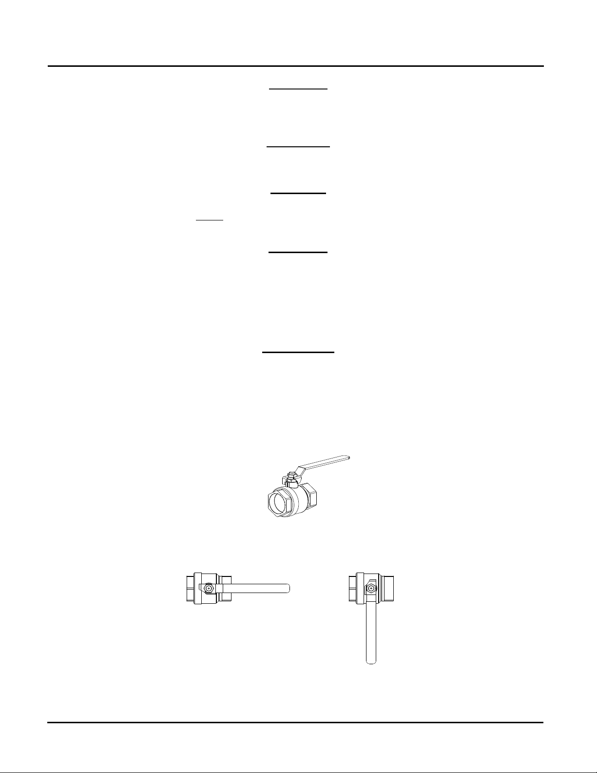
MANUAL GAS SHUTOFF VALVE
VALVE OPEN
VALVE CLOSED
CHAPTER 1: SAFETY PRECAUTIONS
electrical voltages up to 120 vac may be used in this equipment. Therefore the cover on the
unit’s power box (located behind the front panel door) must be installed at all times, except
Must be observed to prevent equipment damage or loss of
operating effectiveness.
WARNING
during maintenance and servicing.
CAUTIONS
CAUTION
Many soaps used for gas pipe leak testing are corrosive to metals.
The piping must be rinsed thoroughly with clean water after leak
checks have been completed.
CAUTION!
DO NOT use this boiler if any part has been under water. Call a
qualified service technician to inspect and replace any part that
has been under water.
1.2 EMERGENCY SHUTDOWN
If overheating occurs or the gas supply fails to shut off, close the manual gas shutoff valve (Figure 1-1)
located external to the unit.
IMPORTANT
The Installer must identify and indicate the location of the
emergency shutdown manual gas valve to operating personnel.
1.3 PROLONGED SHUTDOWN
After prolonged shutdown, it is recommended that the startup procedures in Chapter 4 and the safety
device test procedures in Chapter 6 of this manual be performed, to verify all system-operating
parameters. If there is an emergency, turn off the electrical power supply to the AERCO boiler and close
the manual gas valve located upstream the unit. The installer must identify the emergency shut-off
device.
Figure 11: Manual Gas Shutoff Valve
Page 10 of 162 PR2: 05/09/12

Benchmark 1.5LN Dual-Fuel Low NOx Boiler
Operation and Maintenance Manual
OMM-0041_0C
GF-121
AERCO International, Inc. • 100 Oritani Dr. • Blauvelt, NY 10913 • Ph: 800-526-0288
CHAPTER 2: INSTALLATION
CHAPTER 2: INSTALLATION
2.1 INTRODUCTION
This Chapter provides the descriptions and procedures necessary to unpack, inspect and install
the AERCO Benchmark 1.5 Dual-Fuel Boiler. Brief descriptions are also provided for each
available mode of operation. Detailed procedures for implementing these modes are provided in
Chapter 5.
2.2 RECEIVING THE UNIT
Each Benchmark 1.5 System is shipped as a single crated unit. The shipping weight is
approximately 1551 pounds. The unit must be moved with the proper rigging equipment for
safety and to avoid equipment damage. The unit should be completely inspected for evidence of
shipping damage and shipment completeness at the time of receipt from the carrier and before
the bill of lading is signed.
NOTE
AERCO is not responsible for lost or damaged freight.
Each unit has a Tip-N-Tell indicator on the outside of the crate. This indicates if the unit has
been turned on its side during shipment. If the Tip-N-Tell indicator is tripped, do not sign for the
shipment. Note the information on the carrier’s paperwork and request a freight claim and
inspection by a claims adjuster before proceeding. Any other visual damage to the packaging
materials should also be made clear to the delivering carrier.
2.3 UNPACKING
Carefully unpack the unit taking care not to damage the unit enclosure when cutting away
packaging materials
A close inspection of the unit should be made to ensure that there is no evidence of damage not
indicated by the Tip-N-Tell indicator. The freight carrier should be notified immediately if any
damage is detected.
IMPORTANT
After unpacking, take off the unit top panel and remove
the strap and packing material at the top of the heat
exchanger. The packing material is located in the area of
the ignitor-injector and staged ignition solenoid on the
burner assembly.
The following accessories come standard with each unit and are either packed separately within
the unit’s packing container or are factory installed on the boiler:
• Pressure/Temperature Gauge
• Spare Spark Ignitor-Injector
• Spare Flame Detector
• ASME Pressure Relief Valve
• Condensate Drain Trap
• 1-1/2” Gas Supply Shutoff Valve
When ordered, optional accessories may be packed separately, packed within the boiler
shipping container, or may be installed on the boiler. Any standard or optional accessories
shipped loose should be identified and stored in a safe place until ready for installation or use.
PR2: 05/09/12 Page 11 of 162
Benchmark 1.5LN Dual-Fuel Low NOx Boiler
Operation and Maintenance Manual
OMM-0041_0C
GF-121
AERCO International, Inc. • 100 Oritani Dr. • Blauvelt, NY 10913 • Ph: 800-526-0288
CHAPTER 2: INSTALLATION
2.4 SITE PREPARATION.
Ensure that the site selected for installation of the Benchmark 1.5 Boiler includes:
• Access to AC Input Power at 120 VAC, 1-Phase, 60 Hz @ 20
• Access to Natural Gas line at a minimum pressure of 4 inches W.C.
• Access to Propane line at a minimum pressure of 4 inches W.C.
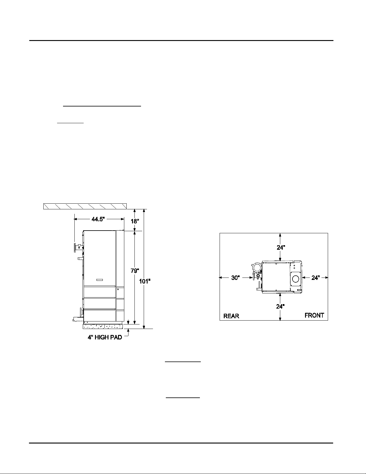
Installation Clearances 2.4.1
The unit must be installed with the prescribed clearances for service as shown in Figure 2-1.
The minimum clearance dimensions, required by AERCO, are listed below. However, if Local
Building Codes require additional clearances, these codes shall supersede AERCO’s
requirements. Minimum acceptable clearances required are:
• Sides: 24 inches
• Front : 24 inches
• Rear: 30 inches
• Top: 18 inches
All gas piping, water piping and electrical conduit or cable must be arranged so that they do
not interfere with the removal of any panels, or inhibit service or maintenance of the unit.
Figure 2-1: Benchmark 1.5 Boiler Clearances
WARNING
KEEP THE UNIT AREA CLEAR AND FREE FROM ALL
COMBUSTIBLE MATERIALS AND FLAMMABLE VAPORS OR
LIQUIDS.
CAUTION
While packaged in the shipping container, the boiler must be
moved by pallet jack or forklift from the FRONT ONLY.
Page 12 of 162 PR2: 05/09/12
Benchmark 1.5LN Dual-Fuel Low NOx Boiler
Operation and Maintenance Manual
OMM-0041_0C
GF-121
AERCO International, Inc. • 100 Oritani Dr. • Blauvelt, NY 10913 • Ph: 800-526-0288
CHAPTER 2: INSTALLATION
FOR MASSACHUSSETTS ONLY:
For Massachusetts installations, the boiler must be installed by a
plumber or gas fitter who is licensed within the Commonwealth of
Massachusetts. In addition, the installation must comply with all
requirements specified in Chapter 1 (Safety Precautions), pages
1-2 & 1-3.
Setting the Unit 2.4.2
The unit must be installed on a 4 inch to 6 inch housekeeping pad to ensure proper condensate
drainage. If anchoring the unit, refer to the dimensional drawings in Appendix F for anchor
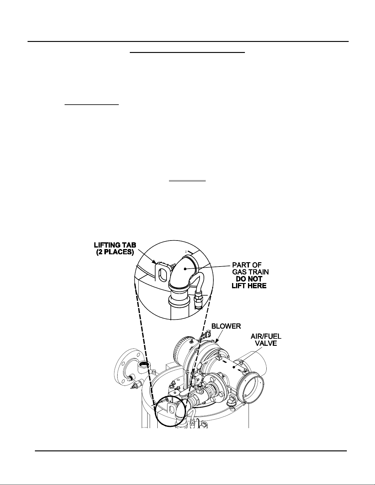
locations. Two lifting tabs are provided at the top of the heat exchanger. Figure 2-2 shows the
location of the tab on the top-left side. The second tab is located on the top-right side of the heat
exchanger. USE THESE TWO TABS TO LIFT AND MOVE THE UNIT. Remove the top panel
from the unit to provide access to the lifting tabs. Remove the four (4) lag screws securing the
unit to the shipping skid. Lift the unit off the shipping skid and position it on the 4 inch to 6 inch
housekeeping concrete pad (required) in the desired location.
WARNING
WHEN LIFTING OR MOVING THE BOILER:
• DO NOT MANIPULATE THE BOILER USING THE GAS
TRAIN OR BLOWER
• WHEN USING THE LIFTING TABS, ENSURE THERE IS
NO LOAD PLACED ON THE GAS TRAIN OR BLOWER
Figure 2-2: Partial Top View Showing Lifting Tab Location
PR2: 05/09/12 Page 13 of 162
Benchmark 1.5LN Dual-Fuel Low NOx Boiler
Operation and Maintenance Manual
OMM-0041_0C
GF-121
AERCO International, Inc. • 100 Oritani Dr. • Blauvelt, NY 10913 • Ph: 800-526-0288
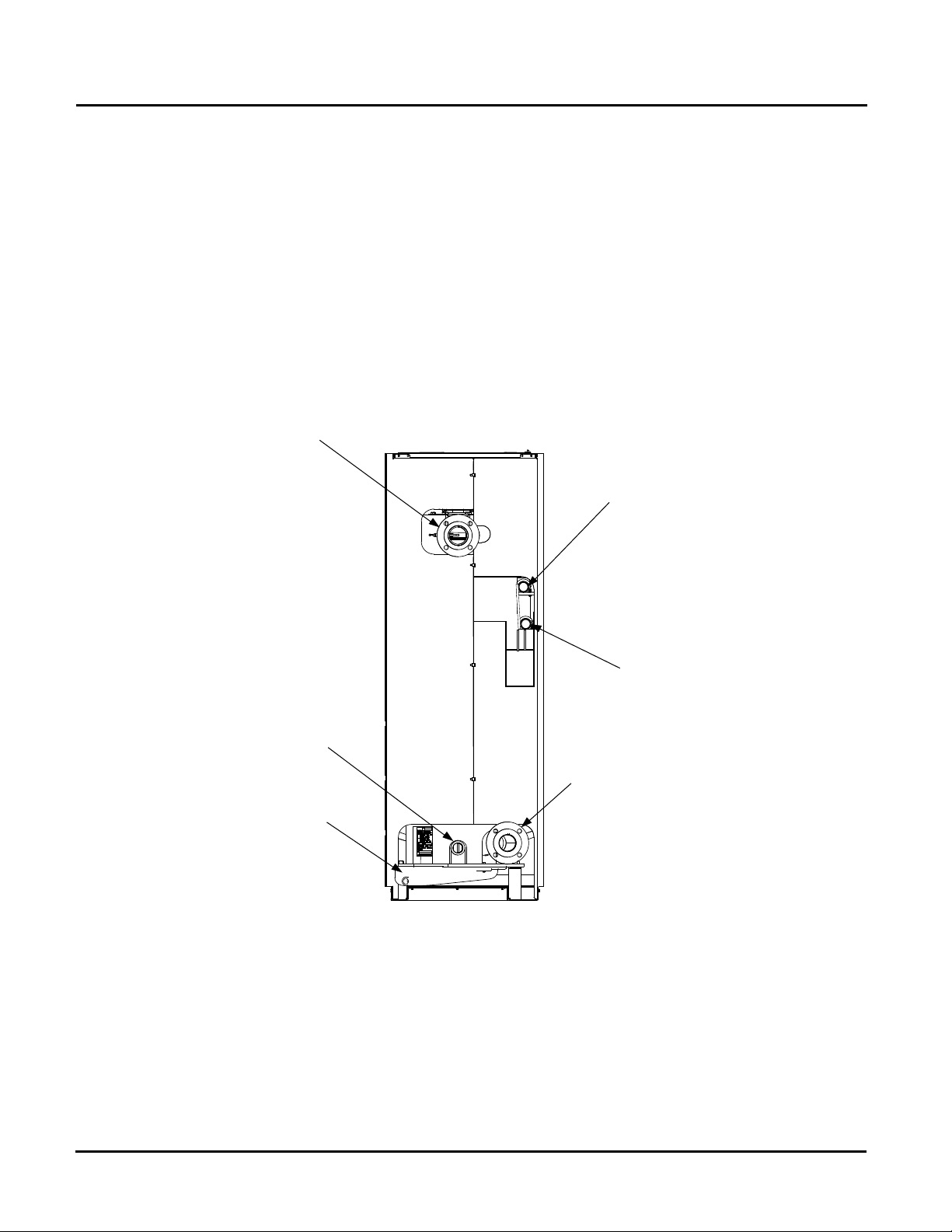
BOILER SUPPLY
3" – 150# FLANGED
CONNECTION
BOILER RETURN
3" – 150# FLANGED
CONNECTION
1-1/2”
NATURAL
GAS INLET
CONNECTION
SHELL DRAIN
VALVE
EXHAUST
MANIFOLD
REAR VIEW
1-1/2”
PROPANE INLET
CONNECTION
CHAPTER 2: INSTALLATION
In multiple unit installations, it is important to plan the position of each unit in advance. Sufficient
space for piping connections and future service/maintenance requirements must also be taken
into consideration. All piping must include ample provisions for expansion.
If installing a Combination Control Panel (CCP) system, it is important to identify the
Combination Mode Boilers in advance and place them in the proper physical location. Refer to
Chapter 5 for information on Combination Mode Boilers.
2.5 SUPPLY AND RETURN PIPING
The Benchmark 1.5 Boiler utilizes 3” 150# flanges for the water system supply and return piping
connections. The physical location of the supply and return piping connections are on the rear of
the unit as shown in Figure 2-3. Refer to Appendix F, Drawing AP-A-832 for additional
dimensional data.
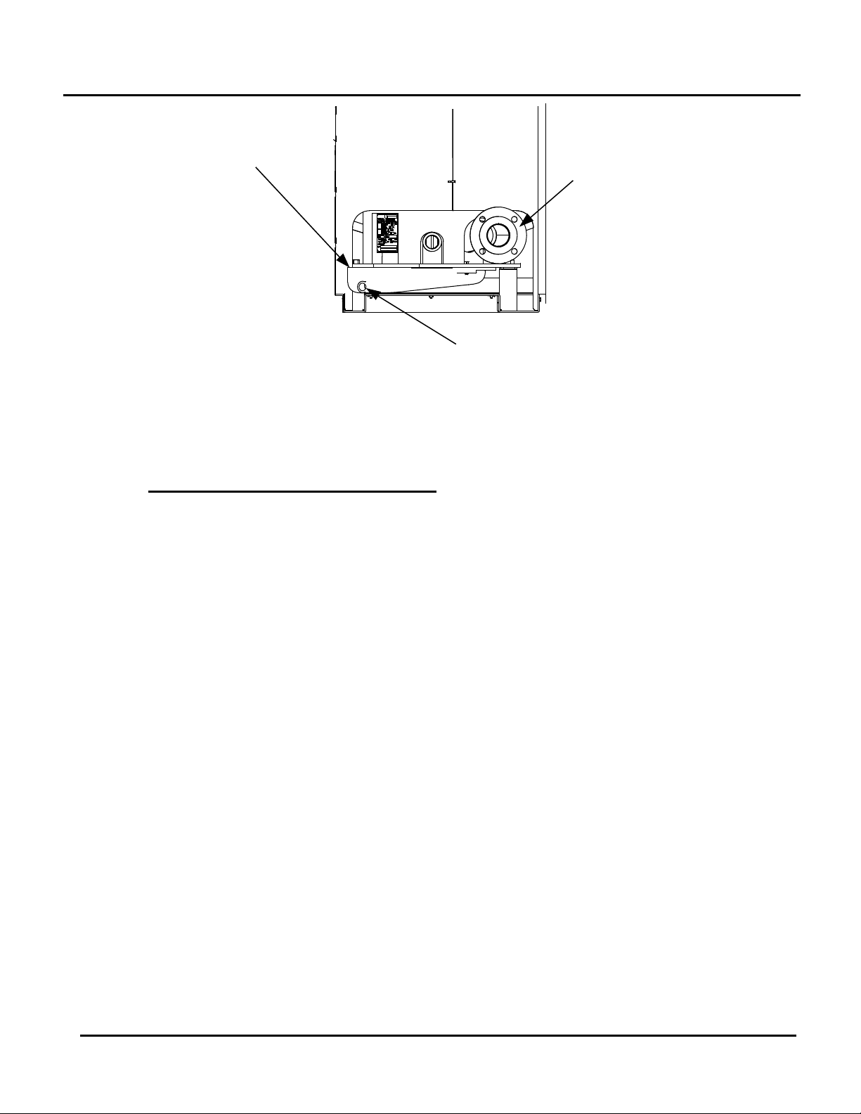
2.6 CONDENSATE DRAIN
The Benchmark 1.5 Boiler is designed to condense water vapor from the flue products.
Therefore, the installation must have provisions for suitable condensate drainage or collection.
The condensate drain pipe located on the exhaust manifold (Figure 2-4) must be connected to a
condensate trap which is packed separately within the unit’s shipping container.
The procedure to install and connect the condensate drain is provided in paragraph 2.6.1.
Figure 2-3: Supply and Return Locations
Page 14 of 162 PR2: 05/09/12
Benchmark 1.5LN Dual-Fuel Low NOx Boiler
Operation and Maintenance Manual
OMM-0041_0C
GF-121
AERCO International, Inc. • 100 Oritani Dr. • Blauvelt, NY 10913 • Ph: 800-526-0288
EXHAUST
MANIFOLD
PARTIAL REAR VIEW
CONDENSATE DRAIN
CONNECTION
BOILER
RETURN
CHAPTER 2: INSTALLATION
Figure 2-4: Condensate Drain Connection Location
Exhaust Manifold Condensate Drain 2.6.1
The exhaust manifold drain pipe connection shown in Figure 2-4, must be connected to a
condensate drain trap external to the unit.
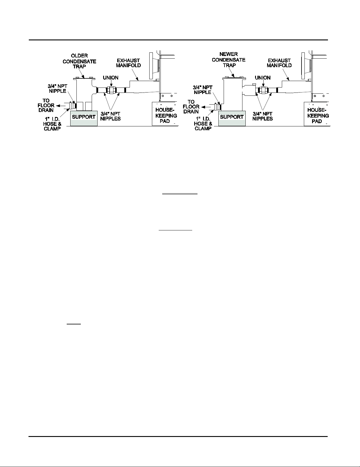
NOTE
There are two slightly different types of condensate traps that may
be used in your configuration; an older style without built-in
adapter, and a newer style with a built-in adapter (see Figure 2-5).
Installation is the same (1/4” threads are inside built-in adapter on
newer style).
Refer to Figure 2-5 and install the trap as follows:
1. Install 3/4” NPT nipples in the tapped inlet and outlet of the condensate trap (part no.
24060).
2. Install a third 3/4” NPT nipple in the tapped condensate outlet of the exhaust manifold.
3. Connect the exhaust manifold nipple to the condensate trap inlet using a female union.
4. install a suitable support under the condensate trap and ensure that the trap is level.
5. Connect a length of 1” I.D. polypropylene hose (part no. 91030) to the nipple on the outlet
side of the condensate trap and secure it with a hose clamp.
6. Route the hose on the trap outlet to a nearby floor drain.
If a floor drain is not available, a condensate pump can be used to remove the condensate to
drain. The maximum condensate flow rate is 20 GPH. The condensate drain trap, associated
fittings and drain lines must be removable for routine maintenance.
PR2: 05/09/12 Page 15 of 162
Benchmark 1.5LN Dual-Fuel Low NOx Boiler
Operation and Maintenance Manual
OMM-0041_0C
GF-121
AERCO International, Inc. • 100 Oritani Dr. • Blauvelt, NY 10913 • Ph: 800-526-0288
CHAPTER 2: INSTALLATION
Figure 2-5: Condensate Trap Installation: Older (left) and Newer (right) Style
2.7 GAS SUPPLY PIPING
The AERCO Benchmark 1.5 Gas Components and Supply Design Guide, GF-4030 must be
consulted prior to designing or installing any gas supply piping.
WARNING
NEVER USE MATCHES, CANDLES, FLAMES OR OTHER
SOURCES OF IGNITION TO CHECK FOR GAS LEAKS.
CAUTION
Many soaps used for gas pipe leak testing are corrosive to metals.
There-fore, piping must be rinsed thoroughly with clean water after
leak checks have been completed.
NOTE
All gas piping must be arranged so that it does not
interfere with removal of any covers, inhibit
service/maintenance, or restrict access between the unit
and walls, or another unit.
Benchmark 1.5 Dual-Fuel units contain two 1-1/2 inch gas inlet connections on the rear of the
unit as shown in Figure 2-3. If one of the fuel sources is not being piped due to its unavailability,
the inlet must be capped.
Prior to installation, all pipes should be de-burred and internally cleared of any scale, metal
chips or other foreign particles. Do Not install any flexible connectors or unapproved gas
fittings. Piping must be supported from the floor, ceiling or walls only and must not be supported
by the unit.
A suitable piping compound, approved for use with natural gas, should be used. Any excess
must be wiped off to prevent clogging of components.
To avoid unit damage when pressure testing gas piping, isolate the unit from the gas supply
piping. At no time should the gas pressure applied to the unit exceed 14” W.C. Leak test all
external piping thoroughly using a soap and water solution or suitable equivalent. The gas
piping used must meet all applicable codes.
Page 16 of 162 PR2: 05/09/12
Benchmark 1.5LN Dual-Fuel Low NOx Boiler
Operation and Maintenance Manual
OMM-0041_0C
GF-121
AERCO International, Inc. • 100 Oritani Dr. • Blauvelt, NY 10913 • Ph: 800-526-0288
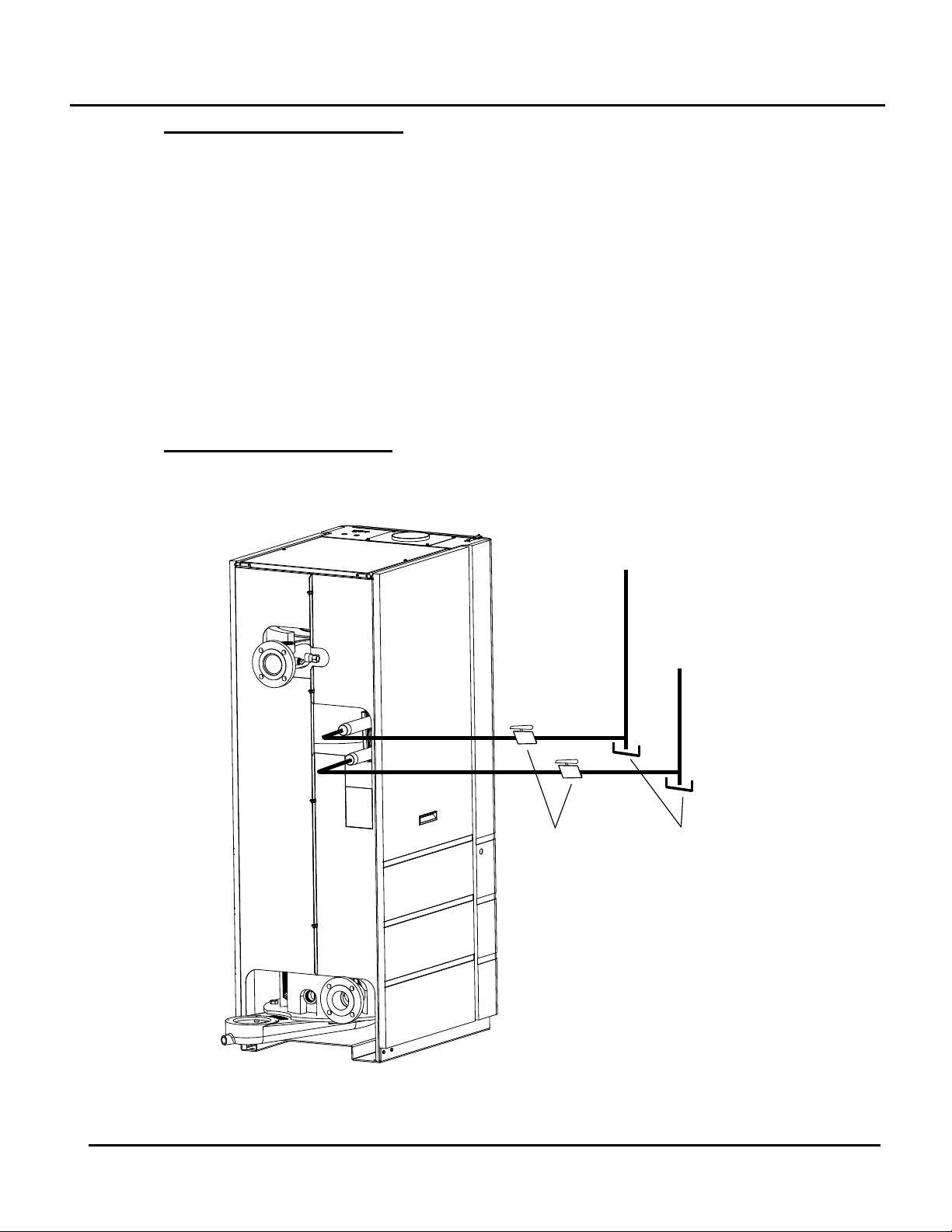
NATURAL
GAS
SUPPLY
PROPANE
SUPPLY
1-1/2" MANUAL
SHUTOFF
VALVES
DIRT
TRAPS
CHAPTER 2: INSTALLATION
Gas Supply Specifications. 2.7.1
The gas supply input specifications to the unit for Natural Gas are as follows:
Natural Gas - The maximum static pressure to the unit must not exceed 14” W.C.. The gas
supply pressure to the unit must be of sufficient capacity to provide 1500 cfh while
maintaining the gas pressure at 4.0 inches W.C. for FM, or 4.2 inches W.C. for IRI gas
trains.
Propane - The maximum static pressure to the unit must not exceed 14” W.C.. The gas
supply pressure to the unit must be of sufficient capacity to provide 600 cfh while
maintaining the gas pressure at 4.0 inches W.C. for FM, or 4.2 inches W.C. for IRI gas
trains.
The maximum static pressure to the unit must not exceed 14” W.C.. The minimum operating
gas pressure for natural gas is 4 inches W.C. for both FM and IRI gas trains when the unit is
firing at maximum input. The gas supply pressure to the unit must be of sufficient capacity to
provide 1500 cfh while maintaining the gas pressure at 4 inches W.C. for FM or IRI gas trains.
Manual Gas Shutoff Valve 2.7.2
A manual shut-off valve must be installed in the gas supply line upstream of the Boiler as shown
in Figure 2-6. Maximum allowable gas pressure to the Boiler is 14” W.C.
Figure 2-6: Manual Gas Shut-Off Valve Locations
PR2: 05/09/12 Page 17 of 162
Benchmark 1.5LN Dual-Fuel Low NOx Boiler
Operation and Maintenance Manual
OMM-0041_0C
GF-121
AERCO International, Inc. • 100 Oritani Dr. • Blauvelt, NY 10913 • Ph: 800-526-0288
UPPER RIGHT CORNER OF FRONT PANEL
TERMINAL BLOCK
CHAPTER 2: INSTALLATION
IRI Gas Train Kit 2.7.3
The IRI gas train is an optional gas train configuration which is required in some areas for code
compliance or for insurance purposes. The IRI gas train is factory pre-piped and wired. See
Appendix F, Drawing AP-A-830 for details.
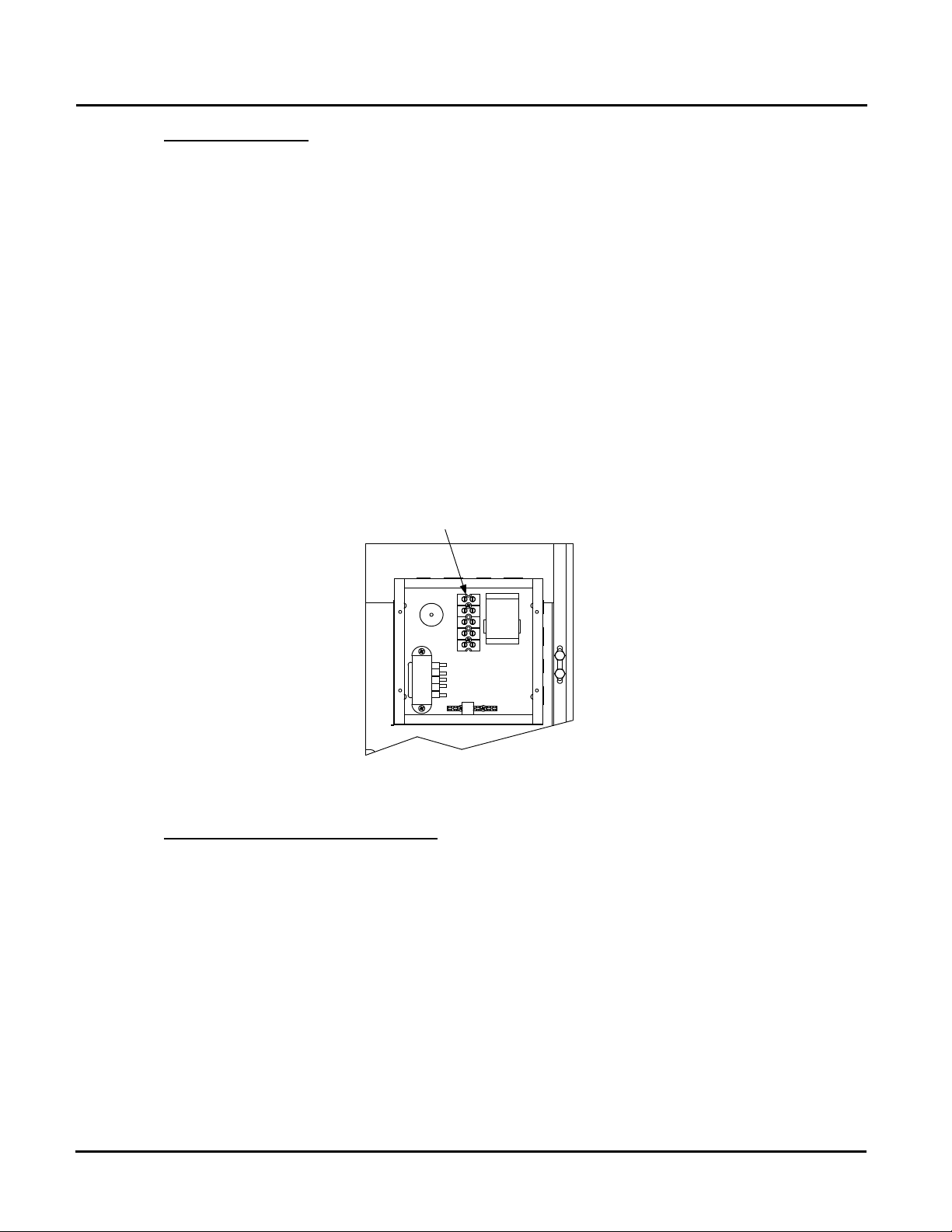
2.8 AC ELECTRICAL POWER WIRING
The AERCO Benchmark 1.5 Electrical Power Wiring Guide, GF-4060, must be consulted prior
to connecting any AC power wiring to the unit. External AC power connections are made to the
unit inside the Power Box on the front panel of the unit. Remove the front door of the unit to
access the Power Box mounted directly above the Control Box. Loosen the four Power Box
cover screws and remove cover to access the AC terminal connections inside the Power Box
(Figure 2-7).
NOTE
All electrical conduit and hardware must be installed so
that it does not interfere with the removal of any unit
covers, inhibit service/maintenance, or prevent access
between the unit and walls or another unit.
Figure 2-7: AC Input Terminal Block Location
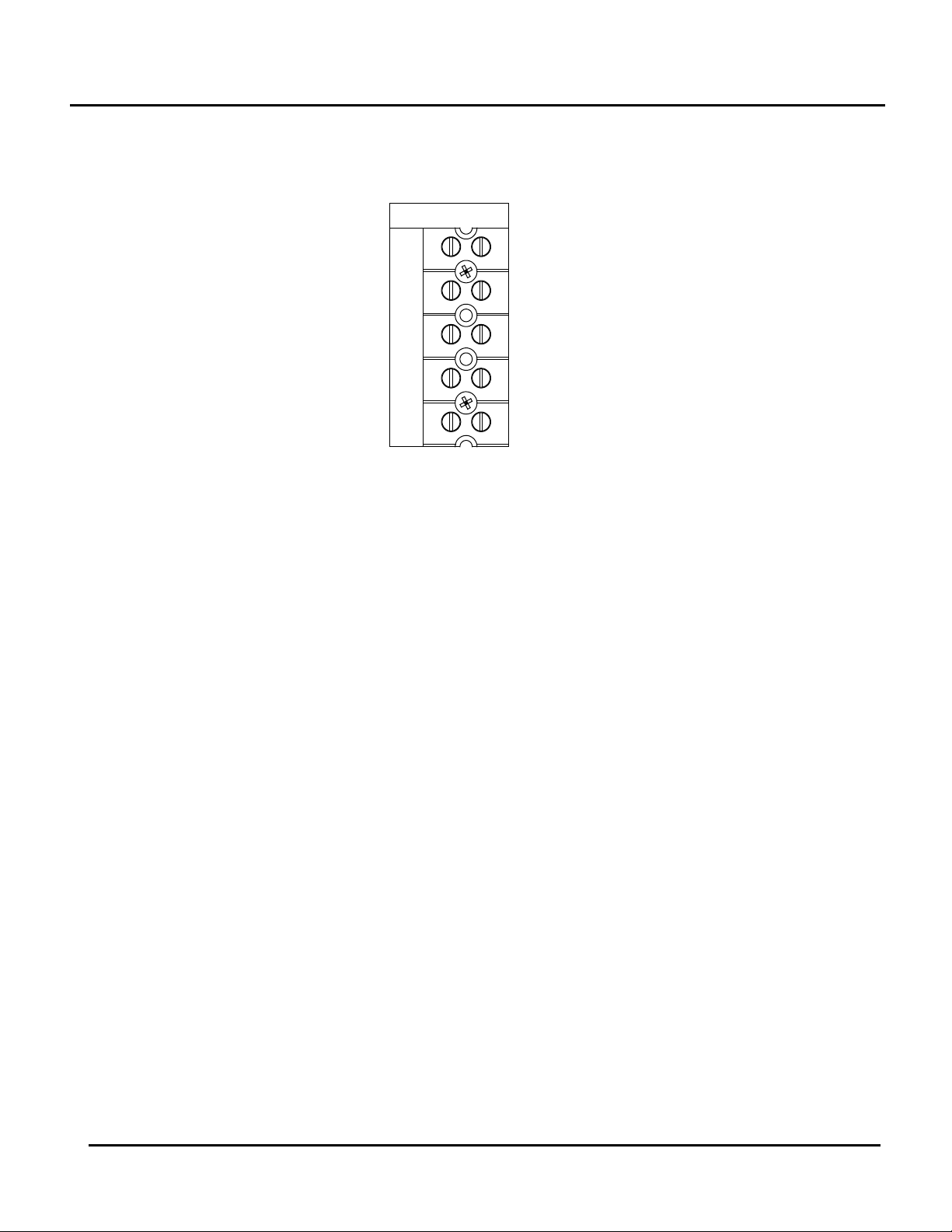
Electrical Power Requirements 2.8.1
The AERCO Benchmark 1.5 Boiler accepts 120 VAC, single-phase, 60 Hz @ 20 A. The Power
Box contains a terminal block as shown in Figure 2-8. In addition, a wiring diagram showing the
required AC power connections is provided on the front cover of the Power Box.
Each Benchmark 1.5 Boiler must be connected to a dedicated electrical circuit. NO OTHER
DEVICES SHOULD BE ON THE SAME ELECTRICAL CIRCUIT AS THE BENCHMARK
BOILER.
A double-pole switch must be installed on the electrical supply line in an easily accessible
location to quickly and safely disconnect electrical service. DO NOT attach the switch to sheet
metal enclosures of the unit.
After placing the boiler in service, the ignition safety shutoff device must be tested. If an external
electrical power source is used, the installed boiler must be electrically bonded to ground in
accordance with the requirements of the authority having jurisdiction. In the absence of such
requirements, the installation shall conform to National Electrical Code (NEC), ANSI/NFPA 70
Page 18 of 162 PR2: 05/09/12
Benchmark 1.5LN Dual-Fuel Low NOx Boiler
Operation and Maintenance Manual
OMM-0041_0C
GF-121
AERCO International, Inc. • 100 Oritani Dr. • Blauvelt, NY 10913 • Ph: 800-526-0288
GND
NEU
L1
120 VAC, 1 PHASE
and/or the Canadian Electrical Code (CEC) Part I, CSA C22.1 Electrical Code.
For electrical power wiring diagrams, see the AERCO Benchmark 1.5 Electrical Power Wiring
Guide, (GF-4060).
CHAPTER 2: INSTALLATION
Figure 2-8: AC Terminal Block Configurations
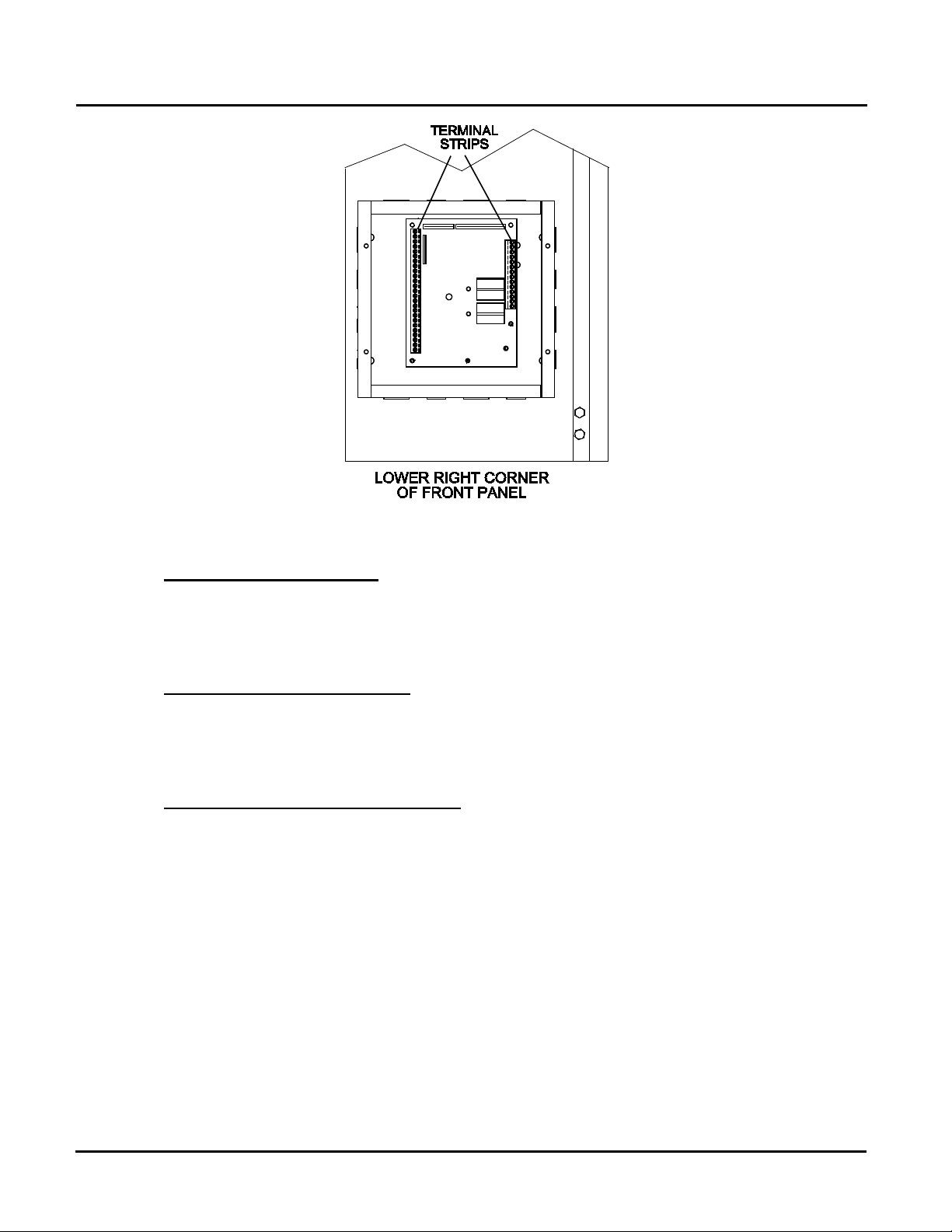
2.9 MODES OF OPERATION AND FIELD CONTROL WIRING
The Benchmark 1.5 Boiler is available in several different modes of operation. While each unit
is factory configured and wired for its intended mode, some additional field wiring may be
required to complete the installation. This wiring is typically connected to the Input/Output (I/O)
Box located on the lower portion of the unit front panel (Figure 2-9) behind the removable front
door.
To access the I/O Box terminal strips shown in Figure 2-10, loosen the four cover screws and
remove the cover. All field wiring is installed from the rear of the panel by routing the wires
through one of the four bushings provided.
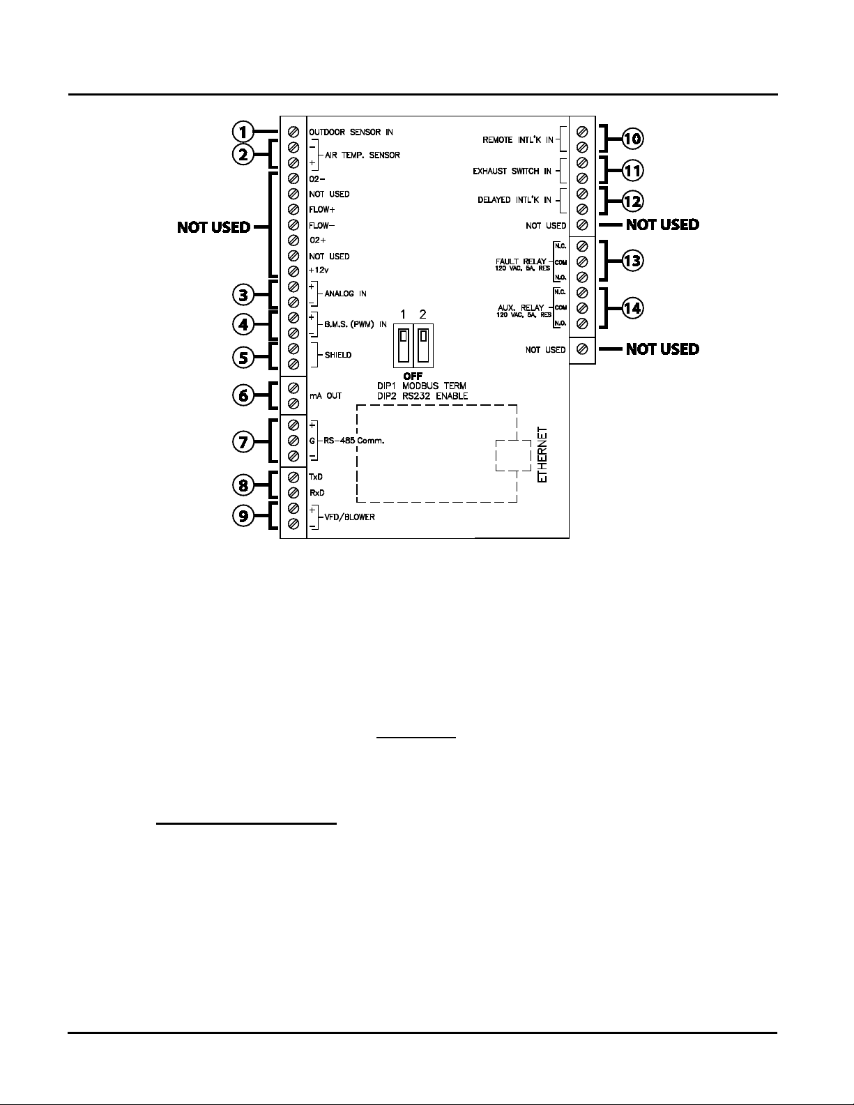
Refer to the wiring diagram provided on the cover of the I/O Box (Figure 2-10) when making all
wiring connections.
Brief descriptions of each mode of operation, and their wiring requirements, are provided in the
following paragraphs. Additional information concerning field wiring is provided in paragraphs
2.9.1 through 2.9.9. Refer to Chapter 5 for detailed information on the available modes of
operation.
PR2: 05/09/12 Page 19 of 162
Benchmark 1.5LN Dual-Fuel Low NOx Boiler
Operation and Maintenance Manual
OMM-0041_0C
GF-121
AERCO International, Inc. • 100 Oritani Dr. • Blauvelt, NY 10913 • Ph: 800-526-0288
CHAPTER 2: INSTALLATION
Figure 2-9: Input/Output (I/O) Box Location
Constant Setpoint Mode 2.9.1
The Constant Setpoint Mode is used when it is desired to have a fixed setpoint that does not
deviate. No wiring connections, other than AC electrical power connections, are required for
this mode. However, if desired, fault monitoring or enable/disable interlock wiring can be
utilized (see paragraphs 2.9.9.1 and 2.9.10).
Indoor/Outdoor Reset Mode 2.9.2
This mode of operation increases supply water temperature as outdoor temperatures decrease.
An outside air temperature sensor (AERCO Part No. 122790) is required. The sensor MUST
BE wired to the I/O Box wiring terminals (see Figure 2-10). Refer to paragraph 2.10.1 for
additional information on outside air temperature sensor installation.
Boiler Management System Mode 2.9.3
NOTE
BMS Model 168 can utilize either pulse width modulation (PWM)
or RS485 Modbus signaling to the Boiler. BMS II Model 5R5-384
and the AERCO Control System (ACS) can utilize only RS485
signaling to the Boiler.
When using an AERCO BMS, BMS II, or ACS (AERCO Control System), the field wiring is
connected between the BMS/BMS II/ACS Panel and each Boiler’s I/O Box terminal strip (Figure
2-10). Twisted shielded pair wire from 18 to 22 AWG must be utilized for the connections. The
BMS Mode can utilize either pulse width modulation (PWM) signaling, or RS485 Modbus
signaling. For PWM signaling, connections are made from the AERCO Boiler Management
System to the B.M.S. (PWM) IN terminals on the I/O Box terminal strip. For RS485 Modus
signaling, connections are made from the BMS/BMS II/ACS to the RS485 COMM terminals on
the I/O Box terminal strip. Polarity must be maintained and the shield must be connected only at
the AERCO BMS/BMS II/ACS. The boiler end of the shield must be left floating.
For additional instructions, refer to Chapter 5, paragraph 5.6 in this manual. Also, refer to GF-
Page 20 of 162 PR2: 05/09/12

Benchmark 1.5LN Dual-Fuel Low NOx Boiler
Operation and Maintenance Manual
OMM-0041_0C
GF-121
AERCO International, Inc. • 100 Oritani Dr. • Blauvelt, NY 10913 • Ph: 800-526-0288
108M (BMS), GF-124 (BMS II Model 5R5-384), and GF-131 (ACS) operation manuals.
CHAPTER 2: INSTALLATION
Remote Setpoint and Direct Drive Modes 2.9.4
The Benchmark 1.5 Boiler can accept several types of signal formats from an Energy
Management System (EMS), Building Automation System (BAS) or other source, to control
either the setpoint (Remote Setpoint Mode) or air/fuel valve position (Direct Drive Mode) of the
Boiler. These formats are:
• 4 to 20 mA/1 to 5 VDC
• 0 to 20 mA/0 to 5 VDC
• PWM – (Pulse Width Modulated signal. See para. 2.10.4)
• Network (RS485 Modbus. See para. 2.10.7)
While it is possible to control a boiler or boilers using one of the previously described modes of
operation, it may not be the method best suited for the application. Prior to selecting one of
these modes of operation, it is recommended that you consult with your local AERCO
representative or the factory for the mode of operation that will work best with your application.
For more information on wiring the 4 to 20 mA / 1to 5VDC or the 0 to 20 mA / 0 to 5 VDC, see
paragraph 2.9.3.
Combination Mode 2.9.5
NOTE
Only BMS Model 168 and ACS can be utilized for the Combination
Mode, not the BMS II (Model 5R5-384).
With a Combination Mode unit, field wiring is between the unit’s I/O Box wiring terminals, the
CCP (Combination Control Panel), and the BMS (Boiler Management System). For ACS
applications, the wiring is between the ACS panel, the ACS Relay panel (optional, depending on
applications), and the RS485 comm terminals in the I/O box. The wiring must be accomplished
using twisted-shielded pair wire from 18 to 22 AWG. Polarity must be maintained.
For further instructions and wiring diagrams, refer to the GF-108 Boiler Management System
Operations Guide and the CCP-1 data sheet (BMS 168 applications)/GF-131 and TAG-0050
(ACS applications).
PR2: 05/09/12 Page 21 of 162
Benchmark 1.5LN Dual-Fuel Low NOx Boiler
Operation and Maintenance Manual
OMM-0041_0C
GF-121
AERCO International, Inc. • 100 Oritani Dr. • Blauvelt, NY 10913 • Ph: 800-526-0288
CHAPTER 2: INSTALLATION
Figure 2-10. I/O Box Terminal Locations and Functions
2.10 I/O BOX CONNECTIONS
The types of input and output signals and devices to be connected to the I/O Box terminals
shown in Figure 2-10 are described in the following paragraphs.
NOTE
Older I/O PCBs are wired the same as new ones, even if silkscreen designations may slightly differ.
CAUTION
DO NOT make any connections to the I/O Box terminals labeled
“NOT USED”. Attempting to do so may cause equipment
damage.
Outdoor Sensor In (1) 2.10.1
An outdoor air temperature sensor (AERCO Part No. 122790) will be required primarily for the
Indoor/Outdoor reset mode of operation. It can also be used with another mode if it is desired to
use the outdoor sensor enable/disable feature. This feature allows the boiler to be enabled or
disabled based on the outdoor air temperature.
The factory default for the outdoor sensor is DISABLED. To enable the sensor and/or select an
enable/disable outdoor temperature, see the Configuration menu in Chapter 3.
The outdoor sensor may be wired up to 200 feet from the boiler. It is connected to the
OUTDOOR SENSOR IN and SENSOR COMMON terminals in the I/O Box (see Figures 2-9 and
2-10). Wire the sensor using a twisted shielded pair wire from 18 to 22 AWG. There is no
polarity to observe when terminating these wires. The shield is to be connected only to the
Page 22 of 162 PR2: 05/09/12

Benchmark 1.5LN Dual-Fuel Low NOx Boiler
Operation and Maintenance Manual
OMM-0041_0C
GF-121
AERCO International, Inc. • 100 Oritani Dr. • Blauvelt, NY 10913 • Ph: 800-526-0288
terminals labeled SHIELD in the I/O Box. The sensor end of the shield must be left free and
ungrounded.
When mounting the sensor, it must be located on the North side of the building where an
average outside air temperature is expected. The sensor must be shielded from direct sunlight
as well as impingement by the elements. If a shield is used, it must allow for free air circulation.
CHAPTER 2: INSTALLATION
Air Temp. Sensor (2) 2.10.2
The Air Temperature Sensor is connected to the positive (+) and negative (-) terminals of the
AIR TEMP. SENSOR on the I/O board. This sensor measures the temperature of the air input to
the Air/Fuel Valve. This temperature reading is one of the components used to calculate the
rotational speed of the blower used in the combustion Calibration process (Chapter 4).
The AIR TEMP. SENSOR terminals can be used to add an additional temperature sensor for
monitoring purposes. This input is always enabled and is a view-only input that can be seen in
the Operating Menu. The sensor must be wired to the positive (+) and negative (-) terminals of
the AIR TEMP. SENSOR and must be similar to AERCO BALCO wire sensor Part No. 12449.
A resistance chart for this sensor is provided in Appendix C.
Analog In (3) 2.10.3
The ANALOG IN + and – terminals are used when an external signal is used to drive the air/fuel
valve position (Direct Drive Mode) or change the setpoint (Remote Setpoint Mode) of the Boiler.
Either a 4 to 20 mA /1 to 5 VDC or a 0 to 20 mA / 0 to 5 VDC signal may be used to vary the
setpoint or valve position. The factory default setting is for 4 to 20 mA / 1 to 5 VDC, however this
may be changed to 0 to 20 mA / 0 to 5 VDC using the Configuration Menu described in Chapter
3. If voltage rather than current is selected as the drive signal, a DIP switch must be set on the
PMC Board located inside the Control Box. Contact the AERCO factory for information on
setting DIP switches.
All of the supplied signals must be floating (ungrounded) signals. Connections between the
signal source and the Boiler’s I/O Box must be made using twisted shielded pair wire from 18 to
22 AWG, such as Belden 9841 (see Figure 2-10). Polarity must be maintained. The shield
must be connected only at the source end and must be left floating (not connected) at the
Boiler’s I/O Box.
Regardless of whether voltage or current is used for the drive signal, they are linearly mapped
to a 40°F to 240°F setpoint or a 0% to 100% valve position. No scaling for these signals is
provided.
B.M.S. (PWM) In (4) 2.10.4
NOTE
Only BMS Model 168 can utilize Pulse Width Modulation
(PWM), but not the BMS II or ACS.
These terminals are used to connect the AERCO Boiler Management System (BMS) to the unit.
The BMS utilizes a 12 millisecond, ON/OFF duty cycle. This duty cycle is Pulse Width
Modulated (PWM) to control valve position. A 0% valve position = a 5% ON pulse and a 100%
valve position = a 95% ON pulse.
Shield (5) 2.10.5
The SHIELD terminals are used to terminate any shields used on sensor wires connected to the
unit. Only shields must be connected to these terminals.
PR2: 05/09/12 Page 23 of 162

Benchmark 1.5LN Dual-Fuel Low NOx Boiler
Operation and Maintenance Manual
OMM-0041_0C
GF-121
AERCO International, Inc. • 100 Oritani Dr. • Blauvelt, NY 10913 • Ph: 800-526-0288
CHAPTER 2: INSTALLATION
IMPORTANT
DO NOT USE the mA OUT output to remotely monitor Setpoint,
Outlet Temp or Fire Rate Out.
mA Out (6) 2.10.6
These terminals provide a 4 to 20 mA output to the VFD (if so equipped) to control the rotational
speed of the blower. This function is enabled in the Configuration Menu (Chapter 3, Table 3-4).
RS-485 Comm (7) 2.10.7
These terminals are used for RS-485 MODBUS serial communication between the unit and an
external “Master” such as a Boiler Management System (BMS or ACS), Energy Management
System (EMS), Building Automation System (BAS) or other suitable device.
TxD, RxD (8) 2.10.8
These terminals provide a parallel connection to the connector on the C-More Controller front
panel, for connecting a computer or laptop.
VFD/Blower (9) 2.10.9
These terminals provide a 0 to 10 volt output to control the rotational speed of the blower. This
function is enabled in the Configuration Menu (Chapter 3, Table 3-4).
Exhaust Switch In (11) 2.10.10
These terminals permit an external exhaust switch to be connected to the exhaust manifold of
the boiler. The exhaust switch should be a normally open type switch (such as AERCO Part No.
123463) that closes (trips) at 500°F.
Interlocks (10, 12) 2.10.11
The unit offers two interlock circuits for interfacing with Energy Management Systems and
auxiliary equipment such as pumps or louvers. These interlocks are called the Remote Interlock
and Delayed Interlock (Figure 2-10). The wiring terminals for these interlocks are located inside
the I/O Box on the unit front panel. The I/O Box cover contains a wiring diagram which shows
the terminal strip locations for these interlocks (REMOTE INTL’K IN and DELAYED INTL’K IN).
Both interlocks, described below, are factory wired in the closed position.
NOTE
Both the Delayed Interlock and Remote Interlock MUST
be in the closed position to allow the unit to fire.
Remote Interlock In
The remote interlock circuit is provided to remotely start (enable) and stop (disable) the Boiler, if
desired. The circuit is labeled REMOTE INTL’K IN and is located inside the I/O Box on the front
panel. The circuit is 24 VAC and is factory pre-wired in the closed (jumpered) position.
(10)
2.10.11.1
Delayed Interlock In
The delayed interlock is typically used in conjunction with the auxiliary relay described in
paragraph 2.11. This interlock circuit is located in the purge section of the start string. It can be
connected to the proving device (end switch, flow switch etc.) of an auxiliary piece of equipment
started by the Boiler’s auxiliary relay. The delayed interlock must be closed for the boiler to fire.
If the delayed interlock is connected to a proving device that requires time to close (make), a
time delay (Aux Start On Dly) that holds the start sequence of the boiler long enough for a
proving switch to make can be programmed. Should the proving switch not prove within the
Page 24 of 162 PR2: 05/09/12
(12)
2.10.11.2

Benchmark 1.5LN Dual-Fuel Low NOx Boiler
Operation and Maintenance Manual
OMM-0041_0C
GF-121
AERCO International, Inc. • 100 Oritani Dr. • Blauvelt, NY 10913 • Ph: 800-526-0288
programmed time frame, the boiler will shut down. The Aux Start On Dly can be programmed
from 0 to 120 seconds. This option is locate in the Configuration Menu (Chapter 3, Table 3-4).
CHAPTER 2: INSTALLATION
Fault Relay (13) 2.10.12
The fault relay is a single pole double throw (SPDT) relay having a normally open and normally
closed set of relay contacts that are rated for 5 amps at 120 VAC and 5 amps at 30 VDC. The
relay energizes when any fault condition occurs and remains energized until the fault is cleared
and the CLEAR button is depressed. The fault relay connections are shown in Figure 2-10.
Auxiliary Relay Contacts (14) 2.10.13
Each Boiler is equipped with a single pole double throw (SPDT) relay that is energized when
there is a demand for heat and de-energized after the demand for heat is satisfied. The relay is
provided for the control of auxiliary equipment, such as pumps and louvers, or can be used as a
Boiler status indictor (firing or not firing). Its contacts are rated for 120 VAC @ 5 amps. Refer to
Figure 2-10 to locate the AUX RELAY terminals for wiring connections.
2.11 FLUE GAS VENT INSTALLATION
The minimum allowable vent diameter for a single Benchmark 1.5 Boiler is 6 inches.
The AERCO Benchmark Venting and Combustion Air Guide, GF-2050, must be consulted
before any flue gas vent or inlet air venting is designed or installed. U/L listed, positive pressure,
watertight vent materials as specified in AERCO’s GF-2050, must be used for safety and code
compliance. Since the unit is capable of discharging low temperature exhaust gases, horizontal
sections of the flue vent system must be pitched back to the unit a minimum of 1/4 inch per foot
to avoid condensate pooling and allow for proper drainage.
The combined pressure drop of vent and combustion air systems must not exceed 140
equivalent feet of 6 inch ducting. Fittings as well as pipe lengths must be calculated as part of
the equivalent length.
For a natural draft installation the draft must not exceed ±0.25 inch W.C. These factors must be
planned into the vent installation. If the maximum allowable equivalent lengths of piping are
exceeded, the unit will not operate properly or reliably.
For Massachusetts boiler installations, the Heatfab Division of the Selkirk Corporation provides
vent systems which conform to all applicable requirements within the Commonwealth of
Massachusetts. Contact information for this supplier is as follows:
Selkirk Corporation, Heatfab Division ( www.heat-fab.com )
130 Industrial Blvd., Turners Falls, MA 01376
Phone: 1-800-772-0739
2.12 COMBUSTION AIR
The AERCO Benchmark Venting and Combustion Air Guide, GF-2050 MUST be consulted
before any flue or combustion supply air venting is designed or implemented. Combustion air
supply is a direct requirement of ANSI 223.1, NFPA-54, CSA B149.1 and local codes. These
codes should be consulted before a permanent design is determined.
The combustion air must be free of chlorine, halogenated hydrocarbons, or other chemicals that
can become hazardous when used in gas-fired equipment. Common sources of these
compounds are swimming pools, degreasing compounds, plastic processing and refrigerants.
Whenever the environment contains these types of chemicals, combustion air must be supplied
from a clean area outdoors for the protection and longevity of the equipment.
The AERCO Benchmark 1.5 Boiler is UL listed for 100% sealed combustion. It can also be
PR2: 05/09/12 Page 25 of 162

Benchmark 1.5LN Dual-Fuel Low NOx Boiler
Operation and Maintenance Manual
OMM-0041_0C
GF-121
AERCO International, Inc. • 100 Oritani Dr. • Blauvelt, NY 10913 • Ph: 800-526-0288
CHAPTER 2: INSTALLATION
installed using room air, provided there is an adequate supply. (See paragraph 2.13.3 for more
information concerning sealed combustion air). If the sealed combustion air option is not being
used, an inlet screen will be attached at the air inlet on the top of the unit
The more common methods of supplying combustion air are outlined below. For more
information concerning combustion air, consult the AERCO Benchmark Venting and
Combustion Air Guide, GF-2050.
Combustion Air From Outside the Building 2.12.1
Air supplied from outside the building must be provided through two permanent openings. Each
opening must have a free area of not less than one square inch for each 4000 BTU/H boiler
input. The free area must take into account restrictions such as louvers and bird screens. For
Canada installations, refer to the requirements specified in CSA B149.1-10, 8.4.1 and 8.4.3.
Combustion Air From Inside The Building 2.12.2
When combustion air is provided from within the building, it must be supplied through two
permanent openings in an interior wall. Each opening must have a free area of not less than
one square inch per 1000 BTU/H of total boiler input. The free area must take into account any
restrictions such as louvers.
Sealed Combustion 2.12.3
The AERCO Benchmark 1.5 Boiler is UL listed for 100%-sealed combustion. For sealed
combustion installations, the screen on the air inlet duct of the unit must be removed. The inlet
air ductwork must then be attached directly to the unit’s air inlet.
In a sealed combustion air application, the combustion air ducting pressure losses must be
taken into account when calculating the total maximum allowable venting run. See the AERCO
Benchmark Venting and Combustion Air Guide, GF-2050. When using the boiler in a sealed
combustion air configuration, each unit must have a minimum 6 inch diameter connection at the
unit.
Temporary Combustion Air Filtering During Construction 2.12.4
When the Benchmark 1.5 Boiler is used to provide heat temporarily during ongoing building
construction, accumulated drywall dust, sawdust and similar particles can accumulate in the
unit’s combustion air intake filter and block combustion air flow. In these situations, AERCO
recommends that a disposable air intake filter be installed, temporarily, above the boiler
combustion air inlet.
AERCO recommends that the temporary air filter be cut from a McMaster-Carr part no.
2122K315 Polyester Air Filter Roll Tackfield, ½” thick, 16” wide, or equivalent. Cover the
Benchmark 1.5 air inlet with the blue side of the filter material facing outward to hold the dust on
the outside surface. Maximize the surface area of the filter covering the 8" diameter opening by
creating a dome out of the filter material.
Cover the flared duct opening with the blue side facing outward. During construction check the
filter for dust accumulation and replace it when the accumulation becomes noticeable.
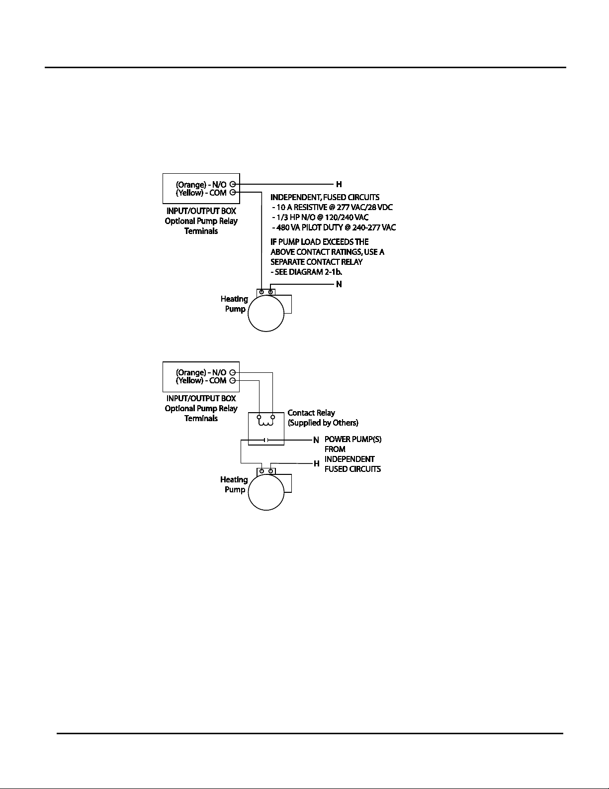
2.13 BENCHMARK PUMP RELAY OPTION
An optional Benchmark pump relay allows the user to turn a pump on/off and open/close a motorized
valve as the boiler cycles on and off on demand. The Pump Delay Timer feature allows the user to keep
the pump running and keep the motorized valve open for up to 30 minutes after the boiler has shut down
and the demand is satisfied.
The Benchmark pump relay (SPDT) contact is rated for:
• 10 A Resistive @ 277 VAC/28 VDC
Page 26 of 162 PR2: 05/09/12
Benchmark 1.5LN Dual-Fuel Low NOx Boiler
Operation and Maintenance Manual
OMM-0041_0C
GF-121
AERCO International, Inc. • 100 Oritani Dr. • Blauvelt, NY 10913 • Ph: 800-526-0288
If pump/valve load exceeds the above contact ratings, use a separate contact relay.
See Diagrams 2-1a and 2-1b.
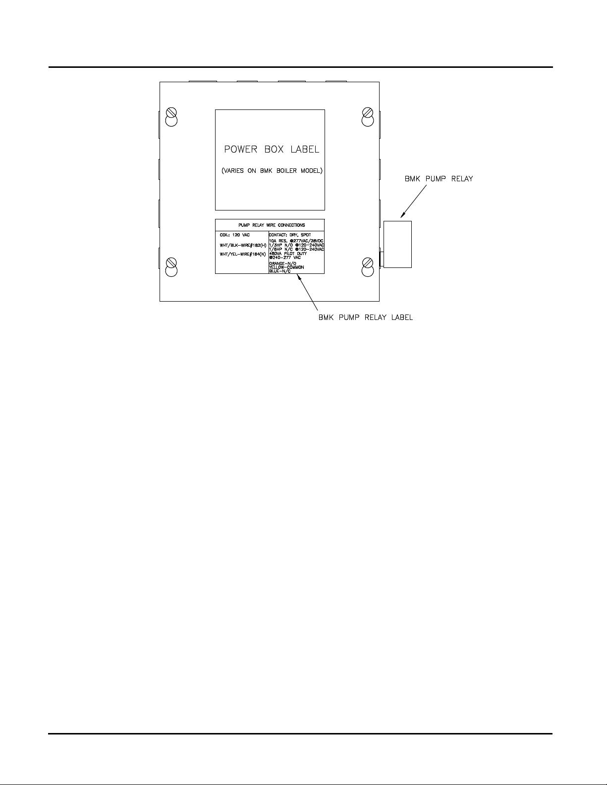
To identify if the boiler is equipped with the BMK Pump Relay Option (part no. 69102), look for the label
and relay as shown in Figure 2-12.
CHAPTER 2: INSTALLATION
• 1/3 HP N/O @ 120/240 VAC
• 1/6 HP N/C @ 120/240 VAC
• 480 VA Pilot Duty @ 240-277 VAC
Diagram 2-1a: Schematic – System Pump Start using Boiler Pump Relay
Diagram 2-1b: Schematic – System Pump Start using a Separate Contact Relay
PR2: 05/09/12 Page 27 of 162
Benchmark 1.5LN Dual-Fuel Low NOx Boiler
Operation and Maintenance Manual
OMM-0041_0C
GF-121
AERCO International, Inc. • 100 Oritani Dr. • Blauvelt, NY 10913 • Ph: 800-526-0288
CHAPTER 2: INSTALLATION
Figure 2-11: Identifying the Presence of BMK Pump Relay Option 69102
Page 28 of 162 PR2: 05/09/12

Benchmark 1.5LN Dual-Fuel Low NOx Boiler
Operation and Maintenance Manual
OMM-0041_0C
GF-121
AERCO International, Inc. • 100 Oritani Dr. • Blauvelt, NY 10913 • Ph: 800-526-0288
CHAPTER 3: CONTROL PANEL OPERATION
3.1 INTRODUCTION
The information in this Chapter provides a guide to the operation of the Benchmark 1.5 Boiler
using the Control Panel mounted on the front of the unit. It is imperative that the initial startup of
this unit be performed by factory trained personnel. Operation prior to initial startup by factory
trained personnel will void the equipment warranty. In addition, the following WARNINGS and
CAUTIONS must be observed at all times.
CAUTION
All of the installation procedures in Chapter 2 must be completed
before attempting to start the unit.
WARNING
ELECTRICAL VOLTAGES IN THIS SYSTEM MAY INCLUDE 460,
208 AND 24 VOLTS AC. IT MUST BE SERVICED ONLY BY
FACTORY CERTIFIED SERVICE TECHNICIANS
WARNING
DO NOT ATTEMPT TO DRY FIRE THE BOILER. STARTING
THE UNIT WITHOUT A FULL WATER LEVEL CAN SERIOUSLY
DAMAGE THE UNIT AND MAY RESULT IN INJURY TO
PERSONNEL OR PROPERTY DAMAGE. THIS SITUATION WILL
VOID ANY WARRANTY.
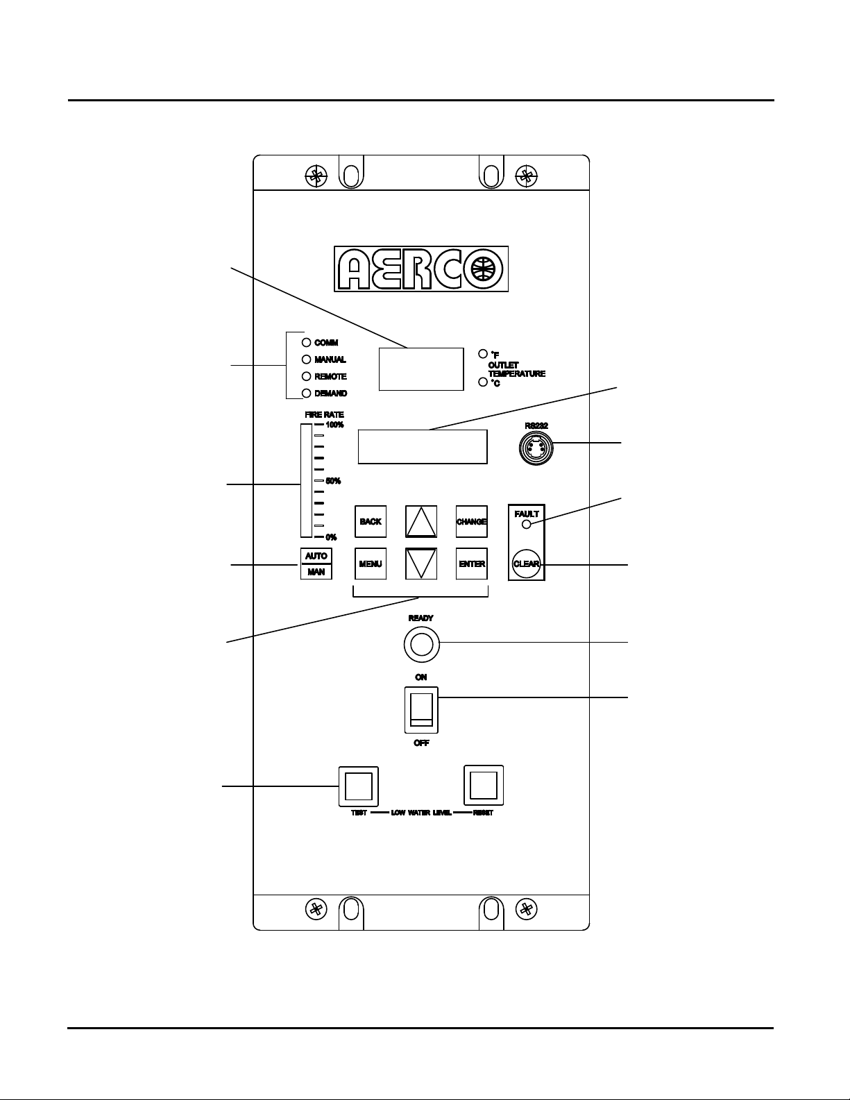
3.2 CONTROL PANEL DESCRIPTION
The Benchmark 1.5 Control Panel shown in Figure 3-1 contains all of the controls, indicators
and displays necessary to operate, adjust and troubleshoot the Benchmark 1.5 Boiler. These
operating controls, indicators and displays are listed and described in Table 3-1. Additional
information on these items are provided in the individual operating procedures provided in this
Chapter.
PR2: 05/01/11 Page 29 of 162
Benchmark 1.5LN Dual-Fuel Low NOx Boiler
Operation and Maintenance Manual
OMM-0041_0C
GF-121
AERCO International, Inc. • 100 Oritani Dr. • Blauvelt, NY 10913 • Ph: 800-526-0288
1
2
3
4
5
6
7
8
9
10
11
12
CHAPTER 3: CONTROL PANEL OPERATION
Figure 3-1: Control Panel Front View
Page 30 of 162 PR2: 05/09/12
 Loading...