

Page 1
Instruction Manual
P/N 30-48XX Dyno-Shaft
,!
WARNING:
Dyno-Shaft On-Vehicle Dynamometer is a valuable diagnostic
tool which must only be used in a safe manner and in
compliance with all applicable laws, rules and regulations. All
users of this product agree that AEM shall not be responsible or
liable for any personal injury, property or any other type or kind
of damage(s) resulting, directly or indirectly, from noncompliance.
AEM Performance Electronics
th
2205 126
Phone: (310) 484-2322 Fax: (310) 484-0152
Street Unit A, Hawthorne, CA. 90250
http://www.aemelectronics.com
Instruction Part Number: 10-4800 Rev D
© 2012 AEM Performance Electronics
Page 2
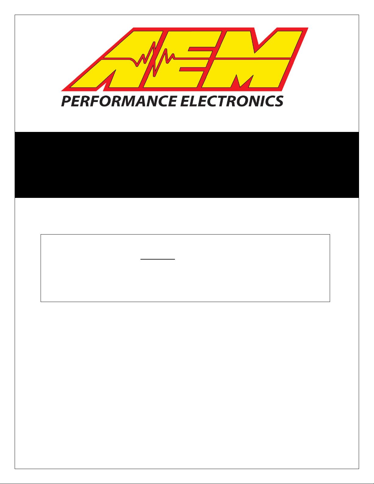
KIT CONTENTS
1 x 35-4740 Dyno-Shaft Controller Assembly
1 x 35-46XX Yoke Assembly (Style and P/N depends on kit purchased)
1 x 35-4780 Dyno-Shaft/AEMnet “Y” Harness
1 x Instruction Manual
Transmission Adapters (quantity and version depends on kit purchased)
Dyno-Shaft Kit Contents
INSTALLATION TIPS
1. Read the entire manual and instructions before beginning the installation.
2. Disconnect the negative battery cable(s) before beginning any work.
3. Make sure all connectors are fully seated and inserted.
4. Make sure all cables are routed away from heat sources or sharp objects.
TABLE OF CONTENTS
• Dyno-Shaft Installation 3
• Connecting to the AQ-1 9
• Using the Dyno-Shaft 10
• Connecting to a Series 2 EMS 15
• Connecting to a 3
• CAN BUS Message Structure 17
• Specifications 18
• Recommended Parts 18
• Replacement Parts 18
• Warranty 19
Page 2 10-4800 Dynoshaft REV D.docx
rd
party display or logger 16
Page 3

DYNO-SHAFT DESCRIPTION
The AEM Dyno-Shaft is a device that measures actual driveshaft torque from yoke
mounted strain gauges. This is not an inaccurate accelerometer based software
application, the AEM Dyno-Shaft provides repeatable, accurate measurement of
driveline torque and horsepower.
It is unaffected by headwind, crosswinds, tailwinds, vehicle weight discrepancies, uphills, down-hills, road surface changes, wheel spin or proximity to other vehicles
because the Dyno-Shaft actually measures driveline torque and RPM, it doesn’t attempt
to estimate it.
The AEM Dyno-Shaft is zero maintenance. Power is supplied to the rotating sensor unit
via an air-core transformer which is formed by the coil on the controller housing and a
matching coil on the sensor. The sensor sends data back to the controller via the same
mechanism. There are no batteries to die, no temperamental slip rings to wear out.
DYNO-SHAFT KIT DIFFERENCES
The Sportsman level kit is designed for applications where a cast iron style transmission
slip yoke is acceptable. The Pro kit is designed for the most demanding applications
and is based around a CNC machined, 4340 chrome-moly yoke.
DYNO-SHAFT INSTALLATION
Make sure that all the work described below is performed 100% per the manufacturer’s
service instructions. If you do not have the proper tools and knowledge to perform the
driveshaft work then take the driveshaft to a machine shop that can perform the work for
you. Absolutely do not attempt to do this work without the proper tools as driveshaft
imbalance or even complete driveline failure is a possibility.
Raise the vehicle per the manufacturer’s instructions. A vehicle hoist is probably best.
Make 100% sure that the vehicle is secure before beginning any work underneath it.
MOUNTING THE DYNO-SHAFT SENSOR
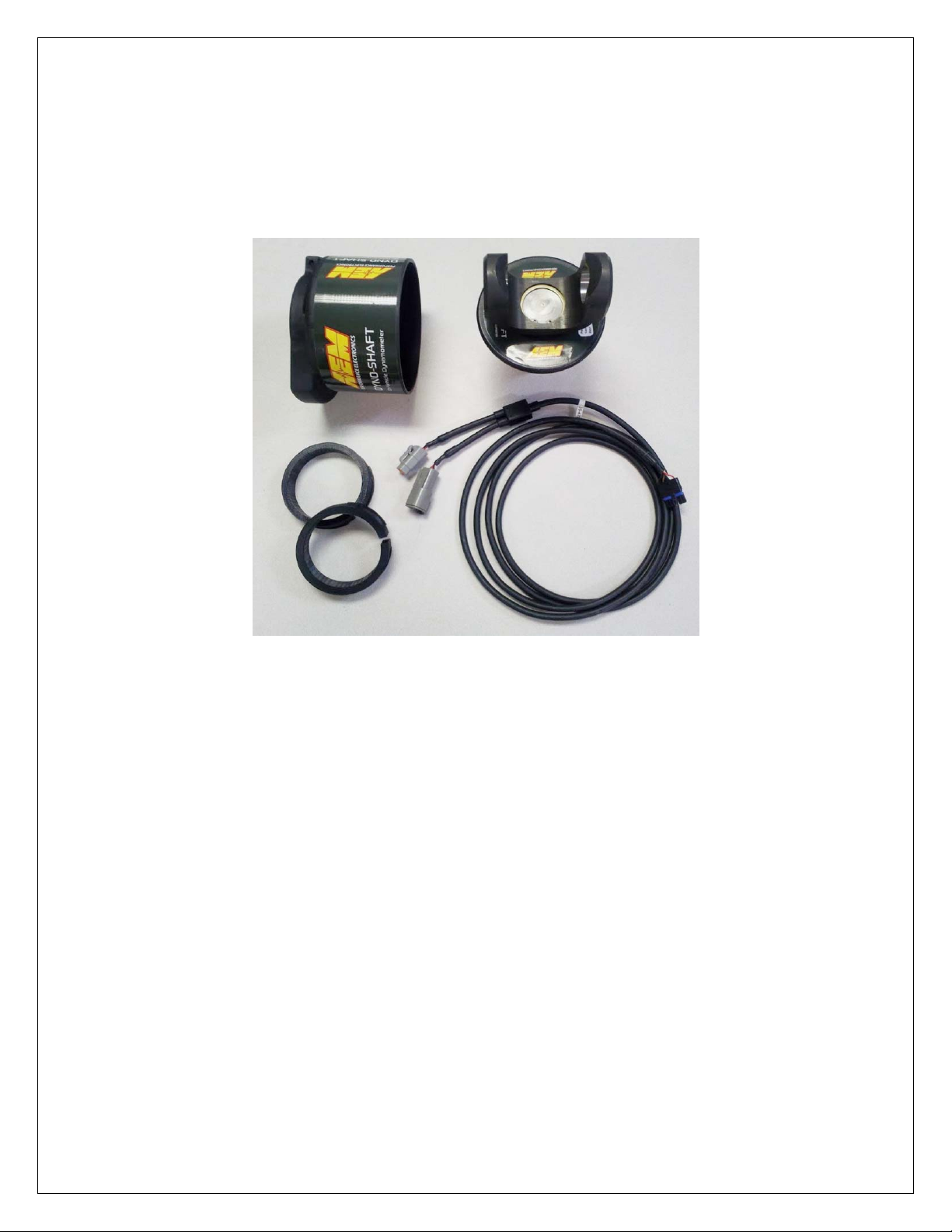
Before attempting to mount the Dyno-Shaft to your vehicle you need to check to make
sure there is proper clearance to fit the device.
Confirm that at least 1.5” of your existing slip yoke’s shaft remains available
outside of your transmission tail housing under all vehicle operating conditions.
If it doesn’t maintain at least this amount then do not attempt the installation.
Shortening the driveshaft or minimizing the driveshaft movement is required
before proceeding.
Confirm that there are no obstructions to mounting the controller behind the
transmission tail shaft housing (see picture).
Page 3 10-4800 Dynoshaft REV D.docx
Page 4
Dyno-Shaft Clearance Requirements
Once you are confident the Dyno-Shaft will fit on your vehicle you can proceed to
remove the driveshaft from the vehicle.
Remove the transmission slip yoke from the driveshaft. This may be a good time to
replace the u-joint with a new unit as they are a high wear item and are inexpensive. In
some cases a conversion u-joint may be necessary to connect the Dyno-Shaft supplied
slip yoke to the driveshaft. Compare which series u-joint your Dyno-Shaft kit is designed
for against your existing u-joint to make sure you purchase the correct u-joint. The
Dyno-Shaft application guide (http://www.aemelectronics.com/images/DynoShaft_Application_Guide.pdf) lists the various Dyno-Shaft kits and their associated ujoint series.
Replace the slip yoke on the driveshaft with the supplied Dyno-Shaft yoke.
Page 4 10-4800 Dynoshaft REV D.docx
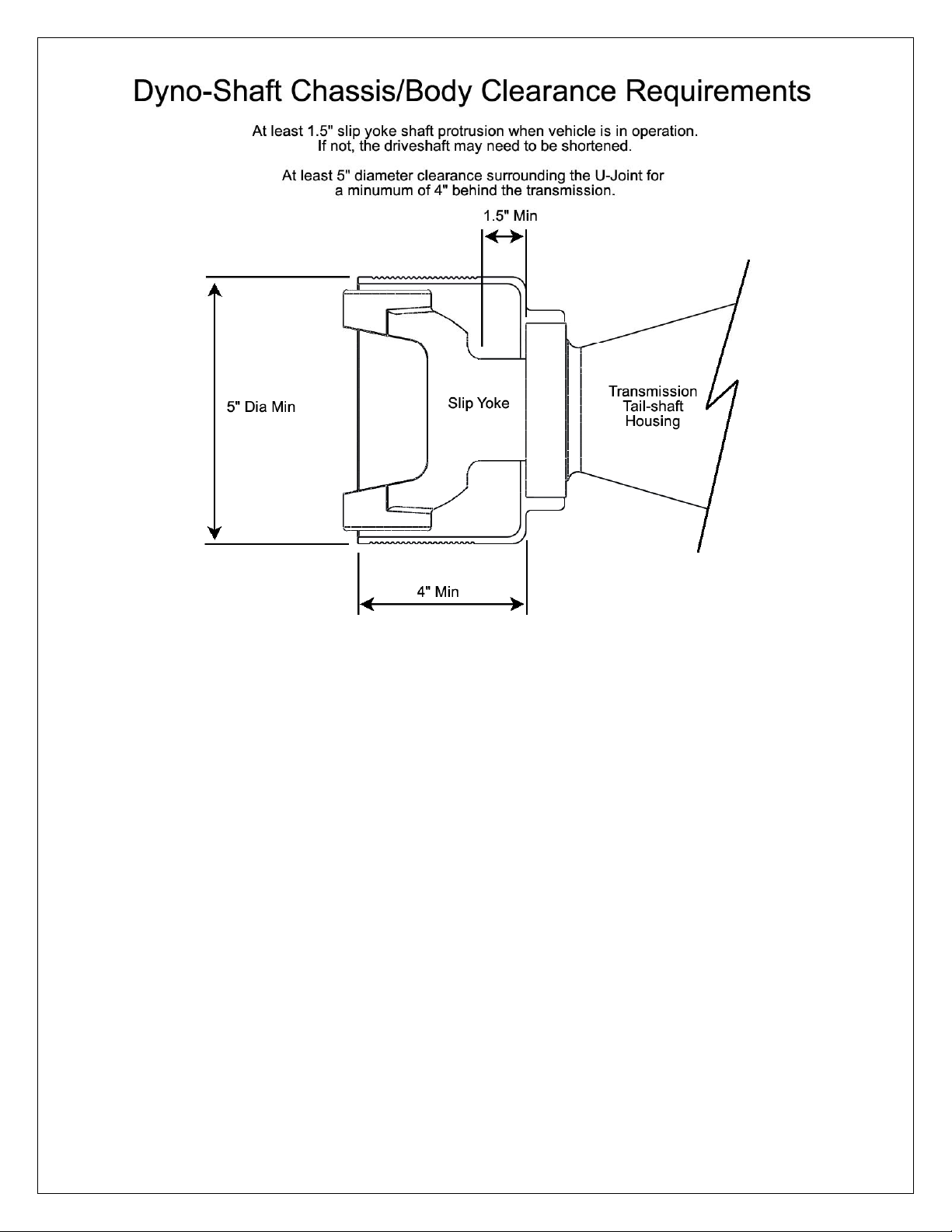
Page 5
Dyno-Shaft sensor mounted on a Pro level Yoke
Re-balance the driveshaft if very high driveshaft RPM (7,000+) is expected.
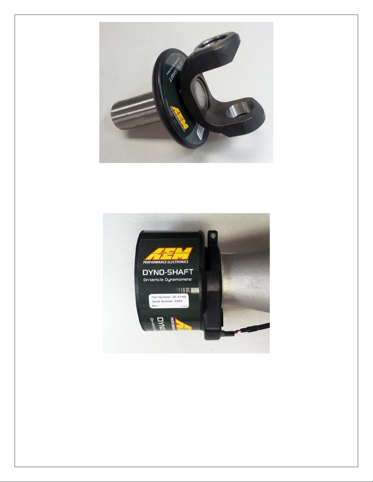
MOUNTING THE DYNO-SHAFT CONTROLLER
Dyno-Shaft Controller
Measure the OD of the transmission tail shaft housing and select the proper adapter. All
of the adapters are identical except for the inner diameter. Select an adapter that fits
over the tail shaft housing without having to be distorted or opened up any.
Place the adapter inside the clamp area of the Dyno-Shaft controller and install on the
tail shaft housing. The locating ribs on the adapters are designed to fit into the cavity
between the clamp arms and controller body. Do not attempt to pry the Dyno-Shaft
clamp area open to make things fit, select a larger ID adapter instead.
Page 5 10-4800 Dynoshaft REV D.docx
Page 6
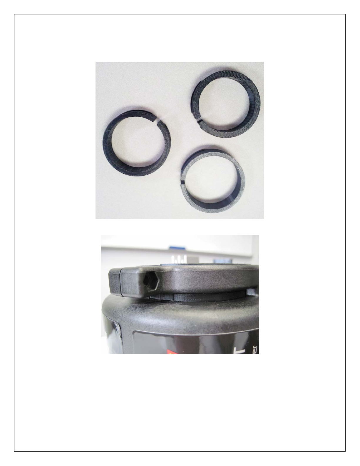
In some cases (notably some T400 and T56 Magnum tail shaft housing castings) the
OD of the housing is just slightly smaller than the ID of the Dynoshaft controller. In this
situation no split adapter can work and a thin, flat, elastic band is supplied to shim up
the OD and act as the adapter and vibration isolation.
Tail shaft Housing Adapters
Proper Fitment of Adapter In Controller Clamp with Locating Ribs Between Clamp
Arms and Controller Body
This is a precision electronic measuring device, therefore you must ensure that hot
exhaust is not in close proximity controller. If there is a heat source near the controller
you *MUST* install a shield between the Dyno-Shaft and the hot component. In order to
protect itself, the Dyno-Shaft controller will automatically shut down when it’s driver
circuit reaches 250 degF. The parameter ”Control Temp” reports this temperature and
can be monitored to make sure the controller does not overheat. If the controller does
Page 6 10-4800 Dynoshaft REV D.docx
Page 7

overheat and automatically shutdown, it will automatically reactivate when the controller
temperature drops to 165 degF. During the over temp shutdown, the controller will
continue to report the “Control Temp” parameter. Parameters such as, Speed, Torque,
Power, Tank Volts, Sensor Volts, Power Level, Sensor Temp, S-Firm Error, Zero Offset
Ok, Good Cal, and LED Aligned, will stop reporting.
Orient the controller so the harness connector is at the top of the transmission unless
there is a heat source nearby. If there is, then orient the controller so the connector is as
far away from the heat source as possible.
Reinstall the driveshaft per the mfg instructions.
Working
Area
Verify proper sensor depth
Verify that the Dyno-Shaft sensor unit on the slip yoke is roughly in the middle of the
controller housing. Adjust the placement of the controller housing front to rear as
necessary. Excessive in/out driveshaft movement may cause the sensor signal to drop
out so ensure this is correct. Also confirm the controller is centered within the sensor
body.
At this point make 100% sure that there is no possibility the rotating sensor can
contact the transmission tail shaft housing or seal under any operating
conditions. If you fail to do this you may permanently damage the sensor!
Attach the supplied cable and route it to the monitoring device. Make sure it is routed
securely, away from heat sources and moving parts. It is imperative that the plug is
oriented correctly in the socket. Although it is a keyed plug, it is possible to install it
incorrectly. The release tab is toward the outside of the controller.
Page 7 10-4800 Dynoshaft REV D.docx
Page 8

Supplied Dyno-Shaft/AEMnet “Y” harness with proper connector orientation
Properly installed Dyno-Shaft connector with labeled wire colors
CONNECTING THE DYNO-SHAFT
The Dyno-Shaft uses the AEMnet electrical interface. AEMnet is an open architecture
software and hardware interface based on the CAN 2.0 specification, which provides
the ability for multiple enabled devices to easily communicate with each other through a
single cable. The hardware connection is made through a Deutsch 4P DTM connector
and contains 12 volt switched power and ground (2A max) as well as the CAN data
lines. Devices connected to the AEMnet transmit data through this one connection and
most of these devices receive power from this same connection as well.
The preferred connection for the Dyno-Shaft is the AEM AQ-1 Data Logger. It
includes the mating connector in its harness and no wiring is required.
Page 8 10-4800 Dynoshaft REV D.docx
Page 9

CONNECTING THE DYNO-SHAFT TO AN AQ-1 DATA LOGGER
The preferred device for configuring & logging the Dyno-Shaft is the 30-2500, AQ-1
Data Logger (sold separately). This logger has been pre-configured for the Dyno-Shaft
and already has the AEMnet connector preinstalled so there is no wiring required.
If using the AQ-1 Data Logger, simply connect the Dyno-Shaft connector to the AEMnet
connector on the AQ-1 Harness.
Within the AQ-1 setup software, the AEMnet page is used to select what parameters
are logged from the AEMnet. Devices connected to AEMnet are automatically detected
and configured when the Auto Discover button is pressed.
AQ-1 AEMnet Dyno Shaft Parameters
Page 9 10-4800 Dynoshaft REV D.docx
Page 10

AEMnet Dyno-Shaft Parameters
Speed – Driveshaft speed in rpm
Torque – Driveshaft torque in ft-lbs
Power – Driveshaft power in HP
Control Volts – Voltage measured at the controller, volts
Tank Volts – Charge voltage for transformer circuit, volts
Sensor Volts – Voltage level generated in the sensor, volts
Power Level – Power transmitted to sensor from controller, percent
Sensor Temp – Temperature measured inside the sensor, degrees F
Frequency - Drive frequency of the transformer circuit, Hz
Control Temp – Temperature measured inside the controller, degrees F
S-Firm Error – Indicates if there is a firmware error in the sensor 1 = Yes, 0 = No
C-Firm Error – Indicates if there is a firmware error in the controller 1 = Yes, 0 = No
Zero Offset OK – Indicates the Auto Zero was successful, 1 = Yes, 0 = No
Good Cal – Indicates the sensor calibration was successfully read 1 = Yes, 0 = No
LED Aligned – Indicates optical pickups on sensor and controller are aligned, 1 =
Aligned, 0 = not aligned
Auto Zero – Auto Zero on or off, 1 = On, 0 = Off
Using the Dyno-Shaft
After the first few times the Dyno-Shaft is used, the sensor zero value will need to be
reset as brand new yokes will twist slightly before they take a final set. This is especially
prevalent on the sportsman yokes. You can check to see if the Dyno-Shaft needs to be
zeroed by putting the vehicle in neutral, brakes off and monitoring the torque value with
no load applied to the driveshaft. A typical value will be less then +/- 2 ft-lbs. Resetting
the zero value is discussed in the section on Dyno-Shaft configuration. New DynoShafts can take an initial set of 100 lbs or more after the first few hard pulls but then
settle down to a repeatable value quickly thereafter.
Configuring the Dyno-Shaft
The Dyno-Shaft is configured using the AEM Dyno-Shaft Configuration window. To
access the configuration window, right click on the Dyno-Shaft in the AEMnet page
window and select Config…
Page 10 10-4800 Dynoshaft REV D.docx
Page 11

Opening the Dyno-Shaft Configuration Window
The AEM Dyno-Shaft Configuration window lists the firmware/hardware versions, as
well as the zero options. The “Zero” button is used to manually reset the zero value of
the Dyno-Shaft. The Auto Zero function allows the Dyno-Shaft to automatically reset
the zero value on power up. Auto Zero Mode is used to turn the Auto Zero function on
or off. The Auto Zero Threshold option sets the threshold for which Auto Zeroing is
active. Auto Zero Threshold is a digital value in “counts”, where three counts is
approximately 1 ft-lb of torque. The Dyno-Shaft will not Auto Zero if the initial torque
reading exceeds the Auto Zero Threshold.
Dyno-Shaft Configuration Window
Page 11 10-4800 Dynoshaft REV D.docx
Page 12

Viewing Dyno Plots Created by the AQ-1
The AQ-1 data log file is viewed from within AEMData.
The Dyno Plot view allows multiple vehicle power and torque data sets to be overlaid in
a special "Dyno Plot" configuration for use with AEM's Dyno-Shaft drive line torque
measurement system.
Also, two additional channels may be plotted against the same X axis in a separate
graph area.
AEMdata Dyno Plot display
Configuration
To display the configuration dialog, click the configure button on the Dyno Plot window
or right click on the view and select 'Configure Dyno Plot...'.
Channel Options
Channel settings are displayed on the first tab of the Dyno Plot Configuration dialog.
Page 12 10-4800 Dynoshaft REV D.docx
Page 13

AEMdata Dyno Plot configuration menus
The channels that are used to generate the plot are selected from here.
• Drive Power - Defaults to "DS Power". This is the log channel that contains the
calculated power data.
• Drive Torque - Defaults to "DS Torque". This is the log channel that contains the
measured torque data.
• Drive Speed - Defaults to "DS Speed". log channel that contains the drive shaft RPM.
• Engine Power - Not currently used.
• Engine Torque - Not currently used.
• Engine Speed - This channel contains the engine RPM data. If this data is available
then it is used to dynamically calculate engine torque & horsepower. If this channel is
not available then engine torque & horsepower will only be available in a single gear
using a user specified transmission ratio.
• 2nd Plot A - The 1st of 2 log channels that will be displayed on the secondary graph.
• 2nd Plot B - The 2nd of 2 log channels that will be displayed on the secondary graph.
Plot Mode X - Defaults to "Drive Shaft Speed". There are four options for the X Axis:
• Drive Shaft Speed, where the Power and Torque will be plotted on the Y-axis vs drive
shaft speed on the X-axis. This is the default setting.
• Engine Speed, Power and Torque will be plotted on the Y-axis versus engine RPM
on the X-axis. For this mode to be used either an Engine Speed channel has to be
defined above or a transmission ratio must be specified. The transmission losses
specified by the user will be used to correct the engine torque values.
• Vehicle Speed, Power and Torque is plotted versus vehicle speed on the X-axis. For
this mode to be used the final drive ratio and tire diameter must be specified.
• Wheel Speed, Power and Torque is plotted versus wheel RPM on the X-axis. For this
mode to be used the final drive ratio must be specified
Plot Mode Y - Defaults to "Drive Torque/Power". There are two options for the X Axis:
Page 13 10-4800 Dynoshaft REV D.docx
Page 14

• Drive Torque/Power, Plots raw drive shaft torque values. These values will typically
be much higher than the engine values due to the gear reduction in lower gears.
• Engine Torque/Power, Plots calculated engine torque and power. Requires either an
Engine Speed log channel or gear ratio to be entered as well as transmission losses.
Smoothing - Applies a smoothing factor to the data.
2nd Plot Split - Defines how much of the plot height is devoted to the primary plot.
Draw Legend - If checked then the summary info is shown on the bottom of the plot.
Atmospheric Power Correction - The method of power correction due to atmospheric
conditions is selected here.
Drive train Options
The drive train options are set on the Drive Tab.
Transmission Ratios
• Engine/Drive Ratio - If you don't have an engine RPM log channel selected in Engine
Speed (above) but you want to get engine Power and Torque values you can enter a
gear ratio here for the gear used to test in. Overdrive gears are less than 1. If this
method is used the Engine power and torque values are only accurate in that gear.
• Final Drive Ratio - Enter the final drive ratio here if you want to plot versus vehicle
speed or wheel speed. Example numbers: 4.11, 3.73, etc...
• Tire Diameter - Enter the tire diameter here if you want to plot versus vehicle speed.
Transmission Losses
• Percentage - This amount of power is assumed to be consumed by the transmission.
Default is 12%
Run Options - Data file to be used is selected in the Run 1 and Run 2 tabs.
Plot Run 1/Plot Run 2 - Defines if this data is displayed on the plot.
Data - Select the log file you wish to use. Using the selection tool, highlight the area of a
trace/graph. Once selected, click “fixed range” to lock in the time span.
Run Info - The date from the source file is entered but you can also override it.
Atmospheric Conditions
• Temperature - Enter the ambient test temperature here.
• Pressure - Enter the ambient pressure during the test here.
• Relative Humidity - Enter the relative humidity during the test here.
Axis - The min & max value for all axis can be set under the Axis tab.
Colors - The chart colors can be defined on the Colors tabs.
Page 14 10-4800 Dynoshaft REV D.docx
Page 15

Sample AEMdata Dyno Plot printout
Print Options - A user defined logo can be added to the hard copy of the dyno printout.
This is selected on the Print Options. A formatted Dyno Plot can be sent directly to a
printer by right clicking on the Dyno Plot window and selecting Print Dyno Plot.
A specially formatted screen capture can be saved as a png graphics file as well. Right
click on the Dyno Plot window and select Print to File.
CONNECTING THE DYNO-SHAFT TO A SERIES 2 EMS
When hooking the Dyno-Shaft to a Series 2 EMS, it is easiest to use the optional flying
lead adapters AEM has created that have been pre-pinned with the correct ECU
terminals for the CAN Bus pins.
AEM Series 2 AEMnet CAN1L CAN1H
EMS Adaptor P/N Pin Location Pin Location
30-6030 30-3430 C22 C21
30-6040 30-3431 A22 C2
30-6050 30-3432 D14 D10
30-6051 30-3432 D14 D10
30-6052 30-3432 D14 D10
30-6053 30-3432 D14 D10
Page 15 10-4800 Dynoshaft REV D.docx
Page 16

30-6060 30-3432 C28 C29
30-6100 30-3433 11A 12A
30-6101 30-3433 11A 12A
30-6300 30-3434 75 13
30-6310 30-3431 77 87
30-6311 30-3431 57/77 67/87
30-6320 30-3435 33 13
30-6600 30-3436 42 12
30-6601 30-3436 42 12
30-6610 30-3437 12 69
30-6611 30-3437 12 69
30-6620 30-3437 57 40
30-6820 30-3438 B29 B28
30-6821 30-3438 B29 B28
Selecting the Dyno-Shaft from the wizards in AEMTuner will auto-configure the CAN
bus receive channels. The data recorded will be available as standard channels within
the data log file.
The power and ground pins on the adapter should be connected to a Switched 12V
source and Ground capable of providing a sustained 1 amp current.
CONNECTING THE DYNO-SHAFT TO A 3rd PARTY DISPLAY OR LOGGER
Most displays and ECU’s that can be configured to monitor user defined CAN data can
be used to capture Dyno-Shaft data as well.
The Dyno-Shaft harness has an AEMnet “Y” adapter containing both male and female
connectors of the AEMnet connector
Connector Body: Deutsch DTM06-4S
Terminals: Deutsch 1062-20-0222 with WM-4S Lock
Connector Body: Deutsch DTM04-4P
Terminals: Deutsch 1060-20-0222 with WM-4P Lock
These two connectors are mates of each other so if you are wiring it in to an external
device pick one and use the P/N’s of the other to determine the required mate.
Dyno-Shaft/AEMnet Pin-out
Pin 1, White, CAN High
Pin 2, Green, CAN Low
Pin 3, Red, Switched 12V. (draws up to 1 amp when active)
Pin 4, Black, Battery Ground
Page 16 10-4800 Dynoshaft REV D.docx
Page 17

DYNO-SHAFT CAN 2.0 MESSAGE STRUCTURE
Configure the CAN message receive function on your device according to the
manufacturer’s specific directions using the following Dyno-Shaft message structure.
CAN 2.0, 29 bit format, 500 kBit/sec, 8 data bytes, big Endian
Message ID: 0x00000160
Transmit Rate: Every 65 ms
Byte Label DataType Scaling Offset Range
0
2
4
6 TorqueFraction 8bitunsigned 0.00390625ft‐lb/bit 0 0to0.99609375ft‐lb
7 PowerFraction 8bitunsigned 0.00390625HP/bit 0 0to0.99609375HP
DriveshaftRPM
DriveshaftTorque
DriveshaftPower
Message ID: 0x00000161
Transmit Rate: Every 65 ms
Byte Label DataType Scaling Offset Range
0
2
4
6 ‐‐‐ ‐‐‐ ‐‐‐ ‐‐‐ ‐‐‐
7 ‐‐‐ ‐‐‐ ‐‐‐ ‐‐‐ ‐‐‐
DriveshaftRPM
DriveshaftTorque
DriveshaftPower
16bit
unsigned 1rpm/bit
16bitsigned 1ft‐lb/bit
16bitsigned 1HP/bit
16bit
unsigned 1rpm/bit
16bitsigned 0.00390625ft‐lb/bit
16bitsigned 0.00390625HP/bit
0
0to65,535RPM1
0
‐32,767to+32,767ft‐lb3
0
‐32,767to+32,767HP5
0
0to65,535RPM1
0
‐128to+128ft‐lb3
0
‐128to+128HP5
Page 17 10-4800 Dynoshaft REV D.docx
Page 18

SPECIFICATIONS
Dyno-Shaft
Operating Current 1A (typical)
Operating Voltage (nominal) 10-18 volts dc
Data Stream 1 x AEMnet
Sample Rate ~15 Hz (65mS)
Max Operating Temp 225 F
Controller Shutdown Temp 250 F
Maximum Torque Based on yoke design
Maximum Dyno-Shaft RPM 10,000 RPM. Note: This is the sensor limits, not your
driveshaft limit.
RECOMMENDED PARTS
30-2500 AQ-1 Data logger
30-2501 AQ-1 Data logger with OBD-2
30-2340 4 Channel UEGO Controller
30-5130 Analog Gauge Style UEGO Controller
30-4100 Digital Gauge Style UEGO Controller
REPLACEMENT PARTS
35-4780 Dyno-Shaft/AEMnet “Y” Harness
Page 18 10-4800 Dynoshaft REV D.docx
Page 19

WARRANTY
12 MONTH LIMITED WARRANTY
Advanced Engine Management Inc. warrants to the consumer that all AEM High
Performance products will be free from defects in material and workmanship for a
period of twelve (12) months from date of the original purchase. Products that fail within
this 12-month warranty period will be repaired or replaced at AEM’s option, when
determined by AEM that the product failed due to defects in material or workmanship.
This warranty is limited to the repair or replacement of the AEM part. In no event shall
this warranty exceed the original purchase price of the AEM part nor shall AEM be
responsible for special, incidental or consequential damages or cost incurred due to the
failure of this product. Warranty claims to AEM must be transportation prepaid and
accompanied with dated proof of purchase. This warranty applies only to the original
purchaser of product and is non-transferable. All implied warranties shall be limited in
duration to the said 12 month warranty period. Improper use or installation, accident,
abuse, unauthorized repairs or alterations voids this warranty. AEM disclaims any
liability for consequential damages due to breach of any written or implied warranty on
all products manufactured by AEM. Warranty returns will only be accepted by AEM
when accompanied by a valid Return Goods Authorization (RGA) number. Product
must be received by AEM within 30 days of the date the RGA is issued.
Please note that before AEM can issue an RGA for any product, it is first necessary for
the installer or end user to contact the AEM Performance Electronics tech line at 1-800423-0046 to discuss the problem. Most issues can be resolved over the phone. Under
no circumstances should a system be returned or a RGA requested before the above
process transpires.
Need additional help? Contact the AEM Performance Electronics tech department at
1-800-423-0046 or tech@aempower.com, or visit the AEM Performance Electronics
forum at http://forum.aempower.com/forum/
Page 19 10-4800 Dynoshaft REV D.docx
 Loading...