


Installation Instructions for P/N 30-3020
Water/Methanol Failsafe
(Injection Monitor)
WARNING:
Completely read this instruction manual before attempting to install or use this product! This installation is not for the electrically or mechanically challenged! Use this system with EXTREME caution! Misuse of this system can damage your engine!
! If you are uncomfortable with anything about this, please refer the installation to an AEM trained tuning shop or call 800-423-0046 for technical assistance. You should also visit the AEM Performance Electronics Forum at http://www.aemelectronics.com.
NOTE: AEM holds no responsibility for any engine damage that results from the misuse of this product!
WATER/METHANOL FAILSAFE PARTS LIST
Qty |
P/N |
Description |
Qty |
P/N |
Description |
1 |
35-3020 |
W/M Failsafe Gauge |
1 |
35-8553W |
Faceplate 1000 White |
1 |
35-2126 |
Flow Sensor with Fittings |
1 |
35-8529S |
Silver Bezel |
1 |
35-3411 |
8-Pin Power Harness |
1 |
35-4302 |
Install Kit (6 Butt Connectors) |
1 |
35-3418 |
4-Pin I/O Harness |
1 |
35-8441 |
Rubber Band |
1 |
35-3415 |
3-Pin Sensor Harness |
1 |
10-3020 |
Inj Mon Instructions |
1 |
35-3010 |
USB Cable |
1 |
|
Faceplate Config Instructions |
1 |
35-8552W |
Faceplate 500 White |
1 |
|
Needle Removal Tool |
1 |
35-8552B |
Faceplate 500 Black |
|
|
|
This product is legal in California for racing vehicles only and should never be used on public highways.
AEM Performance Electronics
2205 126th Street Unit A, Hawthorne, CA. 90250
Phone: (310) 484-2322 Fax: (310) 484-0152
http://www.aemelectronics.com
Instruction Part Number: 10-3020 Rev 02
2011 AEM Performance Electronics

INSTALLATION DIAGRAM
OVERVIEW
Water/methanol injection is used to lower air charge temps and reduce detonation which allows for aggressive tuning to be utilized while using a low octane base fuel. When relying heavily on water/methanol injection a safety device is strongly recommended in order to prevent detonation and possible engine damage in the event of a leak or clog. Progressive injection systems have a dynamic flow output and monitoring both the injection flow rate and the injection percentage means a high level of engine protection can be achieved.
The AEM Water/Methanol Failsafe is an advanced safety device that allows the end user to closely monitor the performance of their water/methanol injection system. Water/Methanol Failsafe collects flow versus injection percentage data points and plots them in a graph to create an injection flow curve using PC configuration software. “Injection percentage” is a calculated value that is indicative of injection pump or injection valve duty cycle and is based on a scale of 0-100 percent.
Once a baseline flow curve is established, the end user can then assign high and low flow threshold lines that can be contoured to closely follow the baseline flow curve. If injection data points occur outside of the high and low flow threshold lines, an alarm condition will be triggered. Injection data points that occur in the area between the high and low flow threshold lines are considered acceptable and an alarm condition will not be triggered.
Once an alarm condition is triggered, two outputs will activate along with a visual alarm alert. The Water/Methanol Failsafe has one high side or +12 volt output and one low side or ground output. Both outputs can be configured to turn on or off when an alarm condition is triggered. These outputs can be used to turn off a boost controller, retard ignition timing, switch fuel and timing maps, activate a warning light or buzzer, or deactivate another external system (nitrous, etc.). The gauge backlighting and needle can also be set to flash to notify the vehicle operator of an alarm condition.
Page 2
The Water/Methanol Failsafe also has an auxiliary input that can be used to trigger an alarm condition. Users with the AEM Water/Methanol Injection System (PN 30-3000 & 30-3001) can use the “Boost Safe” ground output to trigger the auxiliary input if any of the internal fault conditions are detected by the AEM progressive controller.
NOTE: It is HIGHLY recommended that the Water/Methanol Failsafe be used in conjunction with the AEM Water/Methanol Injection Filter (AEM part# 30-3003). Using a filter will maximize the performance and longevity of your flow sensor as well as your entire injection system.
INSTALLATION
1.Disconnect the negative battery cable.
2.Temporarily install gauge without bracket into desired mounting location. Gauge mounts into a 2 1/16” (52MM) hole. The supplied rubber band can be used as a spacer around the gauge if it fits loosely in mounting hole.
3.Splice into injection line and install flow sensor as close as practically possible to final injection point. Flow sensor can be installed before or after check valves or flow control solenoids. A filter is highly recommended and should be installed ahead of the sensor. Ensure arrow on flow sensor points in the direction of flow. Avoid exposing flow sensor to high heat sources (exhaust, turbo, etc.). Route flow sensor cable to gauge mounting location.
4.Install USB cable so the PC end of the cable is easily accessible and route the gauge end of cable to the gauge mounting location. USB cable is meant to be permanently installed to gauge and left in vehicle. Stow PC end of cable in location such as glove box or center console, etc.
5.Install the 4 & 8 pin harnesses and connect wires as described below:
8 Pin Power Harness
Color |
Label |
Description |
Red |
PWR |
Constant power; connect to a fused constant +12V power source |
Black |
GND |
Ground; connect to good chassis ground or directly to battery negative (−) terminal |
Pink |
IGN PWR |
Ignition power; connect to a fused key on +12V power source |
Grey |
LIGHT |
Gauge backlighting; connect to instrument lighting dimmer wire |
White |
ANALOG + |
*OPTIONAL* 0-5V analog output for flow; connect white wire to + analog input and brown |
Brown |
ANALOG − |
wire to − analog input of data logger or EMS; see note below |
4 Pin Input & Output Harness
Color |
Label |
Description |
Yellow |
HI SIDE |
+12V output; connect to an external auxiliary device (1.5A max current) |
Blue |
LOW SIDE |
Ground output; connect to an external auxiliary device (1.5A max current) |
|
|
*OPTIONAL* Auxiliary alarm input; if using AEM Water/Methanol Injection System, connect |
Green |
AUX |
to the green wire of progressive controller (Boost Safe output); other injection systems may |
|
|
connect to optional ground switch (fluid level, etc.) input |
|
|
Injection percentage input; if using AEM Water/Methanol Injection System, tap orange wire |
Orange |
INJ PER |
of progressive controller; all others tap wire that connects from progressive controller to |
|
|
pump |
6.NOTE: The analog output is a differential output so the brown wire should be connected to an analog ground input for best results. If the EMS, logger or similar device does not have an analog ground input, the brown wire should be connected to a sensor ground. If no sensor ground is available, the brown wire should be connected to a power ground. The brown wire must be connected in order to obtain correct flow readings from the analog output.
7.Connect all cables and wiring harnesses to gauge. Fully install gauge into hole using mounting bracket and nuts.
PC SOFTWARE
Download and install the Water/Methanol Failsafe configuration software from the AEM Performance Electronics forum at http://forum.aempower.com/forum/. Open the configuration software and connect the USB cable to the PC. If permanent power is present the Water/Methanol Failsafe will turn on with ignition key-on power. Alternatively, the Water/Methanol Failsafe can be bench-programmed outside of the vehicle without powering it by connecting just the USB cable, however, the backlighting, needle and warning lights will not activate.
Page 3

Water/Methanol Failsafe Configuration Tab
This is the section where the flow monitoring and alarm output functionality of the Water/Methanol Failsafe is configured.
Flow vs. Injection Graph
Description
Displays flow vs. injection percentage data points. Flow points will be populated live whenever the PC is connected to the Water/Methanol Failsafe and injection is occurring. The current injection percentage and flow rate values are shown live on the right side of the graph. This is also where the high and low flow limit lines are established.
Graph
Button |
Description |
|
Auto Scale |
Scales the graph down to best resolution; the graph automatically scales up in the event flow |
|
data is collected beyond the highest shown flow value |
||
|
||
Auto Set Limits |
Automatically sets the upper and lower flow limit lines based on an average of the collected flow |
|
data points |
||
|
||
Reset Limits |
Resets the upper flow limit line to max and the lower flow limit line to zero |
|
Clear Graph |
Clears all the displayed flow data points from the graph; does not clear stored flow data from |
|
logger |
||
|
Logger
Button |
Description |
|
Download Log |
Downloads all the collected flow data that is stored in the logger; will prompt to save log to disk; |
|
log files saved as .daq for direct viewing in AEMdata program |
||
|
||
Clear Log |
Clears all stored flow data from the logger |
Page 4

Alarm Configuration
Option |
Description |
|
Aux Input Status |
Shows the status of the auxiliary alarm input; on or off |
|
Alarm Delay |
Period of time that measured flow can be outside the upper and low flow limit lines before an |
|
alarm condition is triggered; 100-1000 milliseconds |
||
|
||
Alarm Reset |
Period of time flow must be within the acceptable range before the alarm will automatically reset; |
|
1-10 seconds |
||
|
||
Disable Auto Reset |
Select to require power cycle to reset alarm; overrides the automatic alarm reset period. NOTE: |
|
this option is only applicable to software version 1.3.0.0 |
||
|
||
12V Output |
Select to turn the 12V output on when an alarm is triggered or to turn the 12V output off when an |
|
alarm is triggered; 1.5 amps max |
||
|
||
GND Output |
Select to turn the ground output on when an alarm is triggered or to turn the ground output off |
|
when an alarm is triggered; 1.5 amps max |
||
|
Alarm Status
Parameter |
Description |
|
Status Indicator |
Color indicates status; green is system ready, red is alarm triggered |
|
Source |
Indicates the source of the alarm condition; possible alarm conditions are high flow, low flow, |
|
auxiliary input, and alarm test |
||
|
||
Alarm Flow |
Flow rate when alarm was triggered; cc/min |
|
Alarm INJ |
Injection percentage when alarm was triggered |
|
Option |
Description |
|
Alarm Test |
Simulates an alarm to test output configuration; test duration set by Alarm Delay value |
|
|
|
Page 5
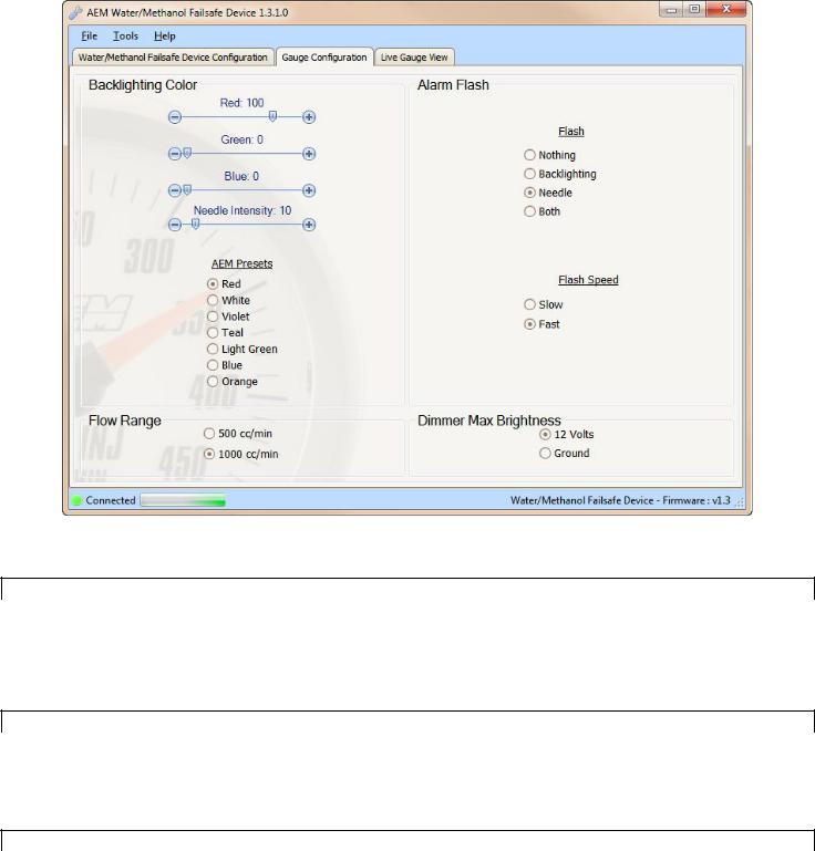
Gauge Configuration Tab
This is the section where the gauge backlighting is configured.
Backlighting Color
Option |
Description |
|
Color Scale |
Adjustable RGB color levels; use to match gauge backlighting to OEM gauge backlighting color |
|
Needle Intensity |
Adjustable intensity level; use to select desired needle brightness |
|
AEM Presets |
Preset backlighting colors to match existing AEM analog gauges; seven color options are red, |
|
white, violet, teal, green, blue and orange |
||
|
Alarm Flash
Option |
Description |
|
Flash |
Select visual output to occur when alarm is triggered; can flash gauge backlight only, flash |
|
needle only, flash both backlight and needle alternately, or do nothing |
||
|
||
Flash Speed |
Select speed of flashing while alarm is triggered; flash slow or fast |
Flow Range & Dimmer Max Brightness
Option |
Description |
|
Flow Range |
Select 500 or 1000 cc/min; gauge face plate must match flow range selection - see additional |
|
instructions for face plate removal information |
||
|
||
Dimmer Max |
Select whether +12V or ground indicates maximum backlighting brightness |
|
Brightness |
||
|
||
Live Gauge View |
|
Page 6
 Loading...