


Part Number 30-2310
INLINE WIDEBAND UEGO CONTROLLER
Figure 1. Wiring Schematic
Inline Wideband UEGO Controller Parts
1 x 30-2310 Inline Wideband UEGO Module
1 x 30-2001 UEGO Sensor
1 x 35-8535 Install Kit (UEGO Bung and 6 Butt Connectors)
1 x 10-2310 Installation Instructions
2 x Zip Tie
INSTALLATION
1.Disconnect the negative battery cable.
2.Find a suitable in-cab or under hood mounting location for the Inline UEGO controller, away from any direct heat or water sources and shielded from the elements. Secure the controller using the supplied zip ties as shown in Figure 3.
3.Connect the flying lead wires as shown in Figure 1.
4.Mount the UEGO sensor as shown in figure 2.
5.Plug the UEGO sensor connector on the UEGO controller into the mating connector on the UEGO sensor.
AEM Performance Electronics
2205 126th Street Unit A, Hawthorne, CA. 90250
Phone: (310) 484-2322 Fax: (310) 484-0152
http://www.aemelectronics.com
Instruction Part Number: 10-2310 Rev 02
© 2011 AEM Performance Electronics
RED - Connect to a switched, fused (5A) 12 volt power source.
BLACK – Connect to a clean power ground.
WHITE - Connect to Lambda + Input.
BROWN - Connect to sensor ground. Connect to power ground if sensor ground is not available.
*GREY – Connect to RS232 serial port on laptop/pc. See section on Serial Data
Viewing
*optional – only needed for laptop/pc viewing of data.
UEGO Sensor Mounting
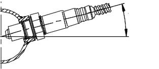
A weld-in UEGO bung is supplied for sensor installation. Mount the UEGO sensor in the exhaust system at least 18 inches downstream from the exhaust port. If you anticipate high EGT's (over 800C), run a turbocharger, run at high RPM for extended periods of time or plan on running leaded race fuel then you must mount the sensor at least 36 inches or more downstream of the exhaust port as all of these can cause the sensor to overheat. On turbocharged engines the UEGO sensor must be installed after the turbo charger, if not, the pressure differential will greatly affect the accuracy of the unit. For accurate readings, the sensor must be mounted before catalytic converters and/or auxiliary air pumps. To prevent collection of liquids between the sensor housing and sensor element during the cold start phase, the installation angle should be inclined at least 10° from horizontal with the electrical connection upwards, see Figure 2.
>10°
Figure 2. Minimum mounting angle for the UEGO Sensor
Controller Mounting
The UEGO controller provides for quick and easy mounting with the supplied zip ties. See Figure 3 below.
Page 2

ZIP TIES
Figure 3. Inline Wideband UEGO Controller Mounting
Indicator Lights
The Inline Wideband UEGO Controller has two indicator lights, see Figure 4. Both the ready light and the status light flash during sensor warm up. Once the sensor reaches operating temperature, usually within 30 seconds, the status light will turn off and the ready light will remain on solid. During sensor warm up, AFR readings may not be accurate. The status light will also flash if a sensor error is detected. The status light will flash on and off a number of times, followed by a short pause. The error codes are listed below in Table 1.
Status Indicator |
|
Ready Indicator |
Light |
Figure 4. Indicator Lights |
Light |
|
|
# of Flashes |
Fault |
Corrective Action |
1-6 |
Sensor Wiring and/or sensor |
Check sensor cable for |
|
|
broken wires/shorts |
7 |
System voltage below 10 volts dc |
Check electrical system |
|
|
for good connections |
|
|
and proper function |
|
Table 1. Error Codes |
|
|
Page 3 |
|
 Loading...