

Page 1
Installation Instructions for
30-4350
AEM Tru Boost
Boost Controller Gauge
WARNING:
This installation is not fo the electrically or mechanically
challenged! Use th EXTREME
uncomfortable with anything about this, please refer the
installation to an AEM trained tuning shop or call 800-423-0046
for technical assistance. You should also visit the AEM
,!
This product is legal in California for racing vehicles onl
Performance Electronics Forum at http://www.aempower.com
NOTE: AEM holds no responsibility for any engine damage tha
esults from the misuse of this product!
r
never be used on public highways.
ADVANCED ENGINE MANAGEMENT INC.
2205 126
Phone: (310) 484-2322 Fax: (310) 484-0152
Instruction Part Number: 10-4350 Rev 090506
© 2006 Advanced Engine Management, Inc.
is gauge with
th
Street Unit A, Hawthorne, CA. 90250
http://www.aempower.com
r
caution! If you are
Page 1
t
y and should
Page 2
EM’s Tru Boost boost controller gauge is a stand-alone boost controller that features a
A
ree digit LED digital readout with 24 sweeping multi color LED’s, two programming
th
uttons, and an on-board pressure sensor. The Tru Boost kit contains all necessary
b
components, including an AEM high performance boost control solenoid, to install and
use the Tru Boost.
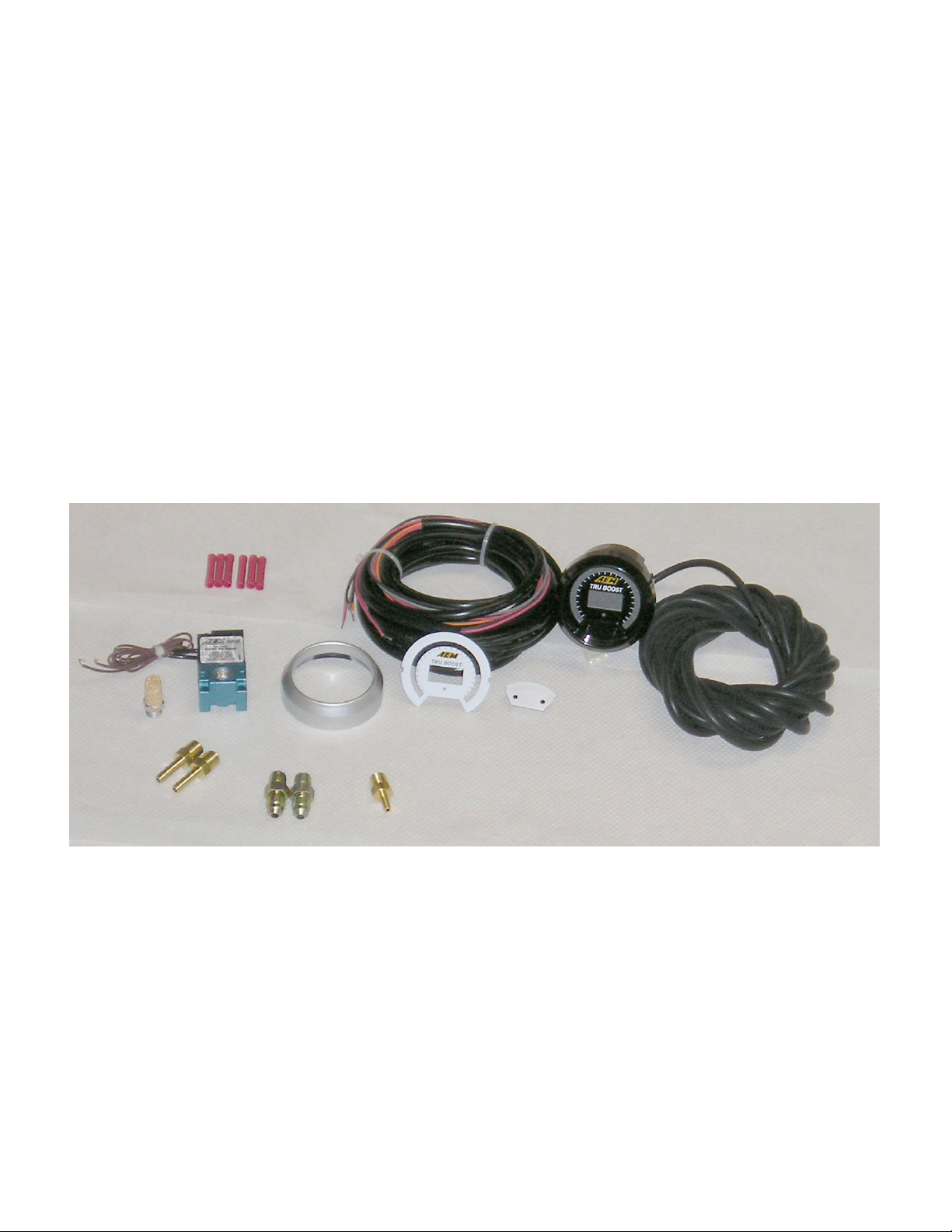
Contents: See Figure 1.
(1) Tru Boost Ga
uge assembly
(1) Appearance kit (Silver bezel, silver pin guide, white faceplate)
(1) Installation kit (Butt
connector, 6 pieces)
(1) Tru Boost cable
(1) Boost solenoid
(1) Instruction manual
(1) Boost hose 10’
(1) 1/8” barb to 1/8”
NPT fitting
(1) Sintered Muffler
(2) –6 to 1/8” NPT f
(2) 3/16” barb to 1/8” NPT fitting
itting
Figure1. Kit Components
Page 2
Page 3
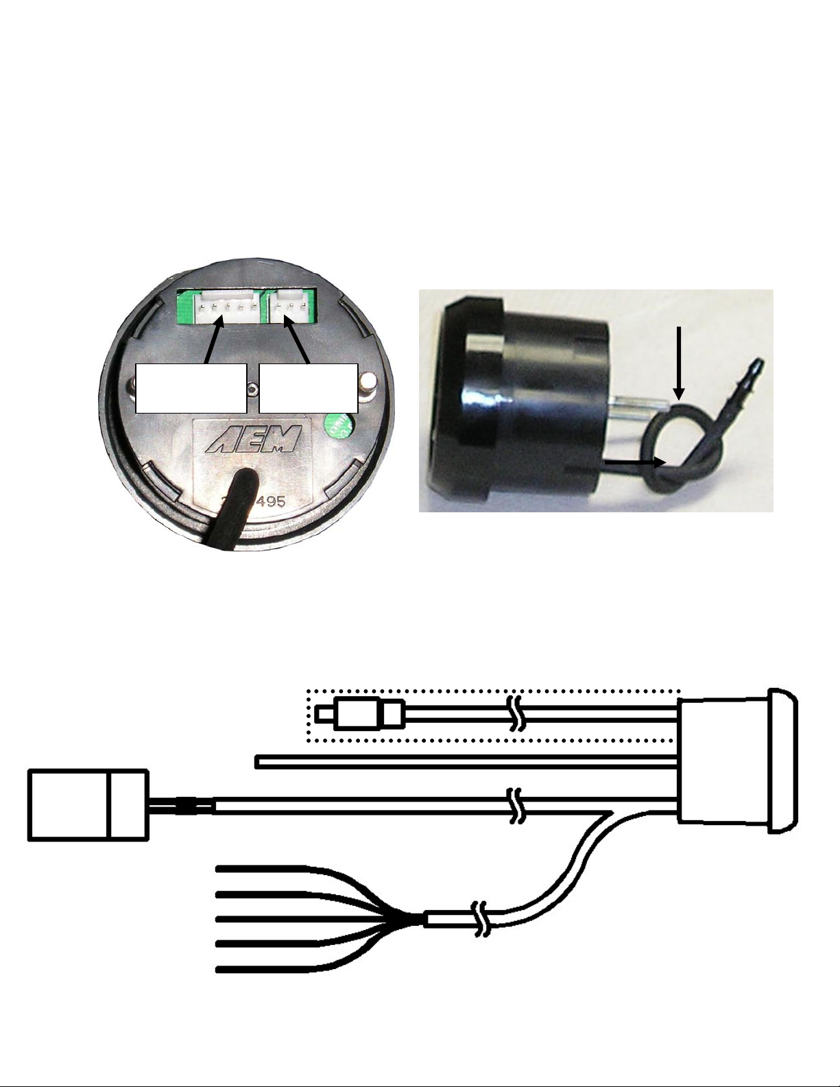
Installing the Gauge
The AEM Tru Boost boost controller gauge requires a standard 2 1/16” (52MM)
ounting hole and can be mounted in a flat panel or most standard gauge pods. The
m
included cable contains
connec t
ts to a mating 5-pin connector on the back of the gauge. See Figure 2. Connec
two wire bundles and a 5-pin connector. The 5-pin connector
the black and red wires in the long 2-wire bundle to the leads from the boost solenoid.
Polarity does not matter. Connect the black wire from the 5-wire bundle to a good
ground. Connect the 2 red wires to a fused, switched, +12Vdc power source. The gray
wire is an optional low side driver output. The orange wire is an optional scramble
boost input. The orange and gray wires do not need to be connected for the gauge
to
function.
Boost Hose
5-pin
connector
Figure 2. Connector Locations
The boost hose protruding from the back
ressure using the on-board pressure sensor, the boost
p sensor. See Figure 3. When
ose must be connected to manifold pressure. Connect the boost hose to manifold
h
pressure using the supplied tubing and 1/8” NPT barb or an existing manifold pressu
port. (NOTE: Do not pull on the boost hose) See Figure 4 for a connection diagram.
OPTIONAL 75 PSIA
SENSOR AND CABLE
MANIFOLD
PRESSURE
RED
B
LACK
BOOST
SOLENOID
D (SWITCHE
RE D, FUSED +12VDC)
RED (SWITC ED, FUSED +12VDC)
H
BLACK (POWER GROUND)
ORANGE (SCRAMBLE BOOST)
G
RAY (LOW SIDE OUTPUT)
3-pin
connector
Figure 4. Connection Diagram
Figure 3. Boost Hose
of the gauge is connected to the on-board
Page 3
re
Tru Boost
Page 4

Scramble Boost Connection (Optional)
Scramble boost is activated when the orange wire is grounded. Connect the
range wire to ground through a switcho as shown in Figure 5.
Switch
Figure 5. Scramble Boost Connection
Warning Light Connection (Optional)
The Tru Boost w is activated. Connect
e grey wire to a warni
ill ground the gray wire when the alarm
ng light as shown in Figure 6. th
Warning Light
+12Vdc Fused
Figure 6. Warning Light Connection
oost Solenoid Connec
B tions
When energized, ports 1 & 2 are connected, when de-energized, ports 2 & 3 are
onnected. The port numbers are clearly noted on the solenoid body. See Figures 7
c
and 8 for plumbing instructions.
Figure 7. External Wastegate Connection
Figure 8. Internal Wastegate Connection
Ground
Page 4
Page 5

xternal Pressure Sensor
E
The Tru Boost is capa
optiona r
l external sensor kit. The 30-4351 sensor kit comes with an AEM 75psia senso
ble of reading boost levels up to 50 psig when using the
and a harness to connect the sensor to the Tru Boost. See Figure 9. Plug the single
row 3-pin connector into the mating connector on the back of the gauge. See Figure 2
.
Plug the black 3-pin connector into the pressure sensor. In order for the Tru Boost to
read the external sensor, the external sensor (E) must be selected in the pressure
sensor (SEn) option.
Figure 9. 30-4351 Tru Boost External Sensor Kit
onfiguring the Tru Boost
C
ser adjustable options. Descriptions of each option, along
with th
The Tru Boost has 9 u
e abbreviation and default value for each option shown in parenthesis, are listed
below:
isplay Units: (UnI - PSI)
D
Use the buttons on th
e front of the gauge to change the units displayed by the
gauge. Select from Psig (PSI), Bar (bAr), and Kpg (PAS).
cramble Boost: (SCb - 10.0)
S
Set the scramble boost du
ty cycle output. Duty cycle can be set between 10%
and 90%. The Tru Boost will output the selected duty cycle when the scramble boost
input is grounded.
cramble Boost Time: (SCr - 0.00)
S
Select the duration of time (0-2
5.5 seconds) the Tru Boost will output the
scramble boost duty cycle when the scramble boost input is grounded.
ressure Sensor: (SEn - I)
P
Select the pressure se
nsor to be used by the Tru Boost. The internal sensor (I)
is used for boost levels up to 29 psig. The optional external sensor (E) is used for boos
levels above 29 psig, up to 50 psig.
t
Page 5
Page 6

larm: (ALA - 30)
A
Set the boos
activated, the LED lights flash yellow and the warning light output (grey wire) is pu
t pressure at which the alarm will activate. When the alarm is
lled to
ground.
pring Pressure: (SPr – 2.00)
S
Enter the waste gate sprin
g pressure(3psi less then your spring). The Tru Boost
will keep the boost solenoid open from 1 psi until boost exceeds the selected value.
This value can be adjusted to reduce lead in boost spikes or reduce spool up time. If
the spring pressure is unknown, a conservative starting value of 5 is suggested.
ar Graph Full Scale: (FUL – 30)
B
Set the full-scale value of the
sweeping LED lights. The LED lights start at 0 psig
and stop at the full-scale value, increasing in 24 equal increments.
oost Setting A: (AXX – A10)
B
Set the output duty cycle
(10%-90%) for setting A. For setting A, the duty cycle
is displayed as “AXX”. When setting duty cycle, the gauge will display the current
manifold pressure. When either button is pressed to increase or decrease duty cyc
le,
the gauge will momentarily display the selected duty cycle before returning to manifold
pressure.
oost Setting B: (bXX – b10)
B
Same as A, except duty c
ycle is displayed as “bXX”.
OTE: While configuring the Tru Boost, the Tru Boost will stay in the
N
programming mode until either the run mode is reached, or the power
is turned
off. Also, since the Tru Boost does not change run modes while in the
programming menu, the corresponding run mode must be selected befo
re
entering the programming menu in order to view real time boost changes.
To enter the program menu, hold both buttons down for 2 seconds and release
then th
e gauge will display “PRG”. Hold both buttons again for 2 seconds and release
to move to the first option. Push both buttons at the same time to move to the next
option. The order of options is shown in the menu tree below. As a shortcut, the ga
uge
will skip to boost setting A if only the left button is pressed after “PRG” is displayed.
Page 6
Page 7

Page 7
Page 8

Using the Tru Boost
The Tru Boost has 3 running modes. In all modes, for manifold pressures less
than 0 psig, the sweeping LED’s remain off, the gauge displays pressure in units of
in-hg, and the displayed values are negative. In mode A, the gauge will output the duty
cycle selected for boost setting A. The gauge will output the duty cycle selected for
boost setting B when in mode B. In the “OFF” mode, the solenoid output is turned off.
Press and hold the left button for 2 seconds to change run modes. The order of run
modes is shown in the menu tree below. The gauge also remembers the peak boost
level achieved. Press and hold the right button for 2 seconds to display the peak boost.
Press and hold the right button for 4 seconds to clear the peak boost value.
Scramble Boost
Scramble boost is a feature that allows the driver to momentarily change the duty
cycle output of the Tru Boost. The output duty cycle for scramble boost is set in the
scramble boost (SCb) option. The scramble boost duration is set by the scramble boost
time (SCr) option. Scramble boost is activated by grounding the orange scramble boost
input wire.
Alarm
All 24 LED lights will flash yellow if manifold pressure exceeds the alarm level for
more than 1 second. The low side driver output will also switch to ground. The LED
lights will continue to flash and the output will stay grounded until either button is
pushed or the gauge is turned off.
Over-Boost
The boost solenoid will shut off and all 24 LED lights will flash red if manifold
pressure exceeds the alarm value by 10% for more than 1 second or if manifold
pressure exceeds the alarm level by 20% for more than 200 milliseconds. The solenoid
will remain off and the LED lights will continue to flash until either button is pushed or
the gauge is turned off.
Page 8
Page 9

Error Detection
ErP- If the external sensor is shorted or disconnected, the LED lights will flash
red and the center digits will display “ErP”. The error code will not activate when using
the internal pressure sensor.
ErS- If the boost solenoid is shorted or disconnected, the LED lights will flash red
and the center digits will display “ErS”. The error code will not activate when the Tru
Boost is on the off mode. Note: The solenoid always has a small pwm signal to allow
for fault detection.
Changing the gauge configuration
The AEM Tru Boost comes configured with the black bezel, black pin guide, and
the black faceplate. However, a silver bezel, a silver pin guide, and a white faceplate
are also included in the gauge kit. To change the faceplate, pin guide, or bezel, orient
the gauge so you are looking at the faceplate. Rotate the bezel counter-clockwise to
unscrew it from the gauge cup. The bezel, lens, pin guide, rubber spacer, faceplate,
diffuser, and anti-glare shield are all removable. Reassemble the gauge as shown in
Figure 10. Make sure the small light holes in the faceplate, diffuser, and anti-glare
shield line up with the light sensor on the circuit board. Do not over tighten the bezel
when reassembling the gauge.
Figure 10. Tru Boost Gauge Assembly
Page 9
Page 10

AEM Electronics warranty
Advanced Engine Management Inc. warrants to the consumer that all AEM High
Performance products will be free from defects in material and workmanship for a
period of twelve (12) months from date of the original purchase. Products that fail within
this 12-month warranty period will be repaired or replaced at AEM’s option, when
determined by AEM that the product failed due to defects in material or workmanship.
This warranty is limited to the repair or replacement of the AEM part. In no event shall
this warranty exceed the original purchase price of the AEM part nor shall AEM be
responsible for special, incidental or consequential damages or cost incurred due to the
failure of this product. Warranty claims to AEM must be transportation prepaid and
accompanied with dated proof of purchase. This warranty applies only to the original
purchaser of product and is non-transferable. All implied warranties shall be limited in
duration to the said 12-month warranty period. Improper use or installation, accident,
abuse, unauthorized repairs or alterations voids this warranty. AEM disclaims any
liability for consequential damages due to breach of any written or implied warranty on
all products manufactured by AEM. Warranty returns will only be accepted by AEM
when accompanied by a valid Return Merchandise Authorization (RMA number.
Product must be received by AEM within 30 days of the date the RMA is issued.
Please note that before AEM can issue an RMA for any electronic product, it is first
necessary for the installer or end user to contact the EMS tech line at 1-800-423-0046
to discuss the problem. Most issues can be resolved over the phone. Under no
circumstances should a system be returned or a RMA requested before the above
process transpires.
AEM will not be responsible for electronic products that are installed incorrectly,
installed in a non approved application, misused, or tampered with.
Any AEM electronics product can be returned for repair if it is out of the warranty period.
There is a minimum charge of $50.00 for inspection and diagnosis of AEM electronic
parts. Parts used in the repair of AEM electronic components will be extra. AEM will
provide an estimate of repairs and receive written or electronic authorization before
repairs are made to the product.
Page 10
 Loading...