

Page 1
Infinity Universal V8 Core Harness
System User Manual
30-3805
THIS PRODUCT IS LEGAL IN CALIFORNIA FOR RACING VEHICLES ONLY
AND SHOULD NEVER BE USED ON PUBLIC HIGHWAYS.
AEM Performance Electronics
AEM Performance Electronics, 2205 126th Street Unit A, Hawthorne, CA 90250
Phone: (310) 484-2322 Fax: (310) 484-0152
http://www.aemelectronics.com
Instruction Part Number: 10-3805
Document Build 6/11/2014
Page 2

AEM Infinity Harness Manuals2
1Introduction
Several universal wiring harness options are available for Infinity products. They range
in complexity from simple plug and pin kits to complete engine harness assemblies that
include power distribution centers. Custom wiring harness projects should only be
undertaken by experienced harness builders. If in doubt, please contact AEM for
recommendations.
30-3805 Universal V8 harness system for Infinity-8/10 systems
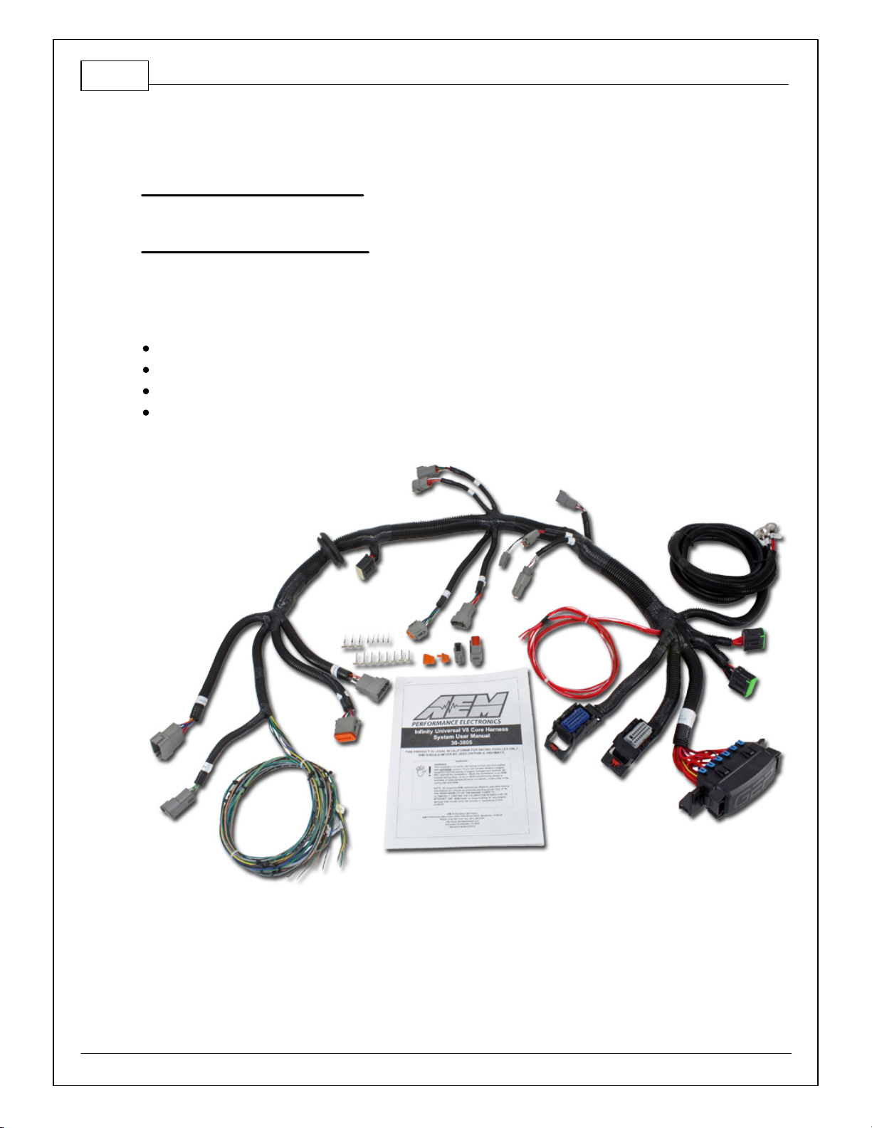
The Infinity Universal V8 Harness system consists of a universal core harness and
optional application specific extensions. It was designed with flexibility in mind. The
harness system includes many features and it can be used in many different
applications.
30-3807 Universal V8 harness system for Infinity-6/8h systems
The Infinity Universal V8 Harness system consists of a universal core harness and
optional application specific extensions. It was designed with flexibility in mind. The
harness system includes many features and it can be used in many different
applications.
30-3705 Universal Mini Harness for Infinity-6/8h systems
This harness is intended to be used as a starting point by experienced harness builders.
It saves time by including basic power distribution features that can be expanded to suit
many application requirements. It allows the harness builder to populate the ECU
connector with only the features needed by the application.
30-3702 Infinity-8/10/12 Mini-harness
This harness is intended to be used as a starting point by experienced harness builders.
It saves time by including basic power distribution features that can be expanded to suit
many application requirements. It allows the harness builder to populate the ECU
connector with only the features needed by the application. Includes 100 96" preterminated leads.
30-3703 Infinity-8/10/12 Mini-harness
This harness is intended to be used as a starting point by experienced harness builders.
It saves time by including basic power distribution features that can be expanded to suit
many application requirements. It allows the harness builder to populate the ECU
connector with only the features needed by the application.
30-3701 Infinity-8/10/12 Plug & Pin Kit
Bare necessities to begin a custom wire harness design. Includes 73 and 56 pin Molex
MX123 harness connectors, terminals and sealing plugs, main relay and relay socket.
30-3704 Infinity-6/8h Plug & Pin Kit
Bare necessities to begin a custom wire harness design. Includes 80 pin Molex MX123
harness connector, terminals and sealing plugs, main relay and relay socket.
This manual is focused primarily on the universal V8 harness system components but it
© 2014 AEM Performance Electronics
Page 3

3
can be used as a reference for any custom harness build based on the Infinity ECU.
Please read the entire User Manual prior to beginning any installation.
2Optional Extension Harnesses for Modular Harness System
Optional extension harnesses compatible with the 3805 V8 harness system are
available.
30-3805-00 GM Injector Adapter Harness
Adapter harness that mates EV1 style injectors in standard GM cylinder order (odd
cylinders on one bank, even cylinders on other) to 30-3805 Core Harness.
30-3805-01 Ford Injector Adapter Harness
Adapter harness that mates EV1 style injectors in standard Ford cylinder order
(cylinders 1-4 on one bank, cylinders 5-8 on other) to 30-3805 Core Harness.
30-3805-02 Single Channel Ignition Adapter Harness
Adapter harness that mates AEM Single Channel Coil Driver (30-2841) to 30-3805
Core Harness. Coil driver takes 5v falling edge ignition trigger signal from Infinity and
outputs a 12v rising edge signal. 12v rising edge signal can either be used to trigger an
inductive coil directly or trigger a single channel CDI box (MSD 6A, etc).
30-3805-03 VR Crank & VR Cam Adapter Harness
Adapter harness that mates variable reluctance (VR) crank and cam sensors to 303805 Core Harness. Legs to each sensor are 48” long.
30-3805-04 VR Crank & Hall Cam Adapter Harness
Adapter harness that mates variable reluctance (VR) crank sensor and Hall Effect cam
sensor to 30-3805 Core Harness. Legs to each sensor are 48” long.
30-3805-05 Hall Crank & VR Cam Adapter Harness
Adapter harness that mates Hall Effect crank sensor and variable reluctance (VR) cam
sensor to 30-3805 Core Harness. Legs to each sensor are 48” long.
30-3805-06 Hall Crank & Hall Cam Adapter Harness
Adapter harness that mates Hall Effect crank and cam sensors to 30-3805 Core
Harness. Legs to each sensor are 48” long.
30-3805-07 GM Stepper Idle Control Adapter Harness
Adapter harness that mates GM stepper idle control valve to 30-3805 Core Harness.
IAC connector is flat and meant for use with later model style control valves.
30-3805-08 Universal PWM Idle Control Adapter Harness
Flying lead to mate universal PWM idle control valve to 30-3805 Core Harness.
Connector to connect to control valve must be provided by end user.
30-3600 O2 Sensor Extension Harness
© 2014 AEM Performance Electronics
Page 4
AEM Infinity Harness Manuals4
Extension harness to connect AEM UEGO Wideband O2 sensor to 6 pin Deutsch DTM
in Infinity Mini Harnesses (30-3702/3703).
30-3601 IP67 Comms Cable
USB Mini-B comms cable; 39” long with right angled connector and bayonet style lock.
30-3602 IP67 Logging Cable
USB A-to-A extension cable: 39” long with right angled connector and bayonet style
lock.
33805 Kit Contents
Universal V8 Core Harness
User Instructions
DTM 8 Way Receptacle Assembly with 8 contacts
DTM 8 Way Plug Assembly with 8 contacts
4ECU Connectors
The Infinity-6/8h/8/10 ECUs use the MX123 Sealed Connection System from Molex.
AEM strongly recommends that users become familiar with the proper tools and
procedures before attempting any modifications or additions to these connector
© 2014 AEM Performance Electronics
Page 5
5
housings. The entire Molex user manual can be downloaded direct from Molex at http://
www.molex.com/mx_upload/family//MX123UserManual.pdf
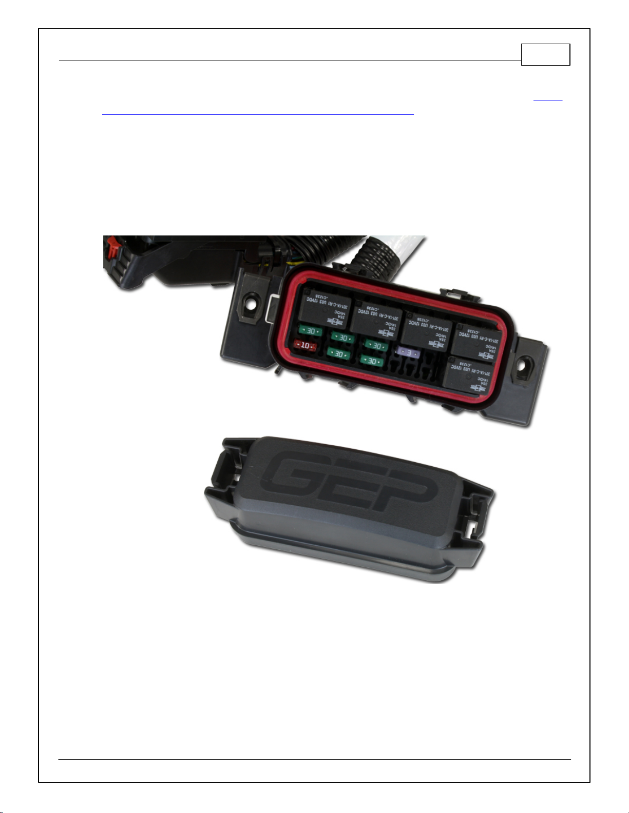
53805 Power Distribution Center
Included in the harness is a Power Distribution Center (PDC), pre-populated with the required relays and
fuses for correct operation of accessory loads. The PDC comes with a bundle of flying leads that need to
be properly wired as part of the installation. Flying leads include switched ignition, an optional fused
+12V relay power output for auxiliary loads, and optional fused +12V relay outputs for a Fuel Pump and
Coolant Fan.
© 2014 AEM Performance Electronics
Page 6

AEM Infinity Harness Manuals6
6Installation Notes
Wiring Conventions and EMI
Some wire harness assemblies come pre-wired with all connectors, fuses, and relays
needed to operate an engine. Harnesses that include a PDC generally require
extension/termination of the flying leads to their appropriate devices, and additional
sensors and other devices can be wired into the harness as needed for the specific
application. The following guidelines should be adhered to while completing the required
wiring.
A proper wiring job includes proper termination of the wire at the sensor. The wire
terminal end must be moisture tight where it plugs into the sensor and it must have
strong, electrically sound terminals. The preferred method of securing a wire to a
terminal is to use a crimp terminal with NO solder. It is important to use the proper
crimping tool for sound terminal construction. Plastic terminal plugs must have moisture
tight seals. Inspect each plug to make sure the seals are in place. Di-electric grease can
be added in the terminal slots to further aid in corrosion resistance.
If a splice into a wire must be made and no solder-less terminals are available, then you
must properly solder the splice.
Noise can be a serious problem and can cause intermittent misfiring of the engine.
Every precaution should be taken to prevent interference to the ECU’s operation.
Resistive plug leads are REQUIRED.
To eliminate or reduce the chance of EMI, wires that carry high current must run in
twisted pairs. An example of this would be the power leads from a multiple spark ignition
system. These ignition systems can carry up to 100 amps for a couple milliseconds at
the time of discharge, which induces a strong magnetic field in close proximity of the
wires.
The routing of the wire loom is critical to EFI system performance and safety. The
following safety considerations should be made when installing the wire loom:
Heat protection: the loom should be placed away from or insulated from sources
of heat. The obvious item(s) that should be avoided are the exhaust manifolds,
EGR delivery tubes, and turbochargers. If it is absolutely necessary to route a
wire in close proximity to any of these items, then a suitable insulator must be
used.
Noise suppression: do not route wires near the HT leads. For coil-on-plug ignition
systems this is not as critical.
Moving component protection: route wires away from moving components such
as fans, the blower belt, or the throttle linkage. Also, make sure the wires are not
under any strain when the engine is at full deflection on the motor mounts.
Never have the wires in exposed bundles throughout the engine compartment.
© 2014 AEM Performance Electronics
Page 7

7
Determining ECU Location
It is recommended that the ECU be placed in an environment that does not
expose it to temperatures above 85° Celsius (160F).
In cases where the Infinity is to be used in place of the stock ECU, the location
that the stock ECU occupied is suitable.
On applications where the ECU is to be located in a different position than stock,
the interior of the vehicle is best.
The Infinity should be located in a place that reduces the length of extension wires
from the PDC while maintaining an environmentally sound location.
The ECU location must permit the PDC to be mounted in a serviceable location.
Power Distribution Center
PDCs included in the harness assemblies generally include all relays and fuses
necessary for proper function and should be mounted in a location which permits
serviceability. Ideally the PDC should be located in the passenger compartment, or if
necessary within the engine compartment as far away from heat sources as can be
achieved. Some PDCs contain flying lead bundles which must be wired to the battery,
fuel pump and radiator fan(s), switched ignition and possibly other interfaces. Routing of
this flying lead bundle should also be taken into account when determining the mounting
location of the PDC.
© 2014 AEM Performance Electronics
Page 8

AEM Infinity Harness Manuals8
73805 Installation Tips
30-3805 Universal Core Harness Installation
Install the core harness in the vehicle as shown in the image above using the firewall
© 2014 AEM Performance Electronics
Page 9
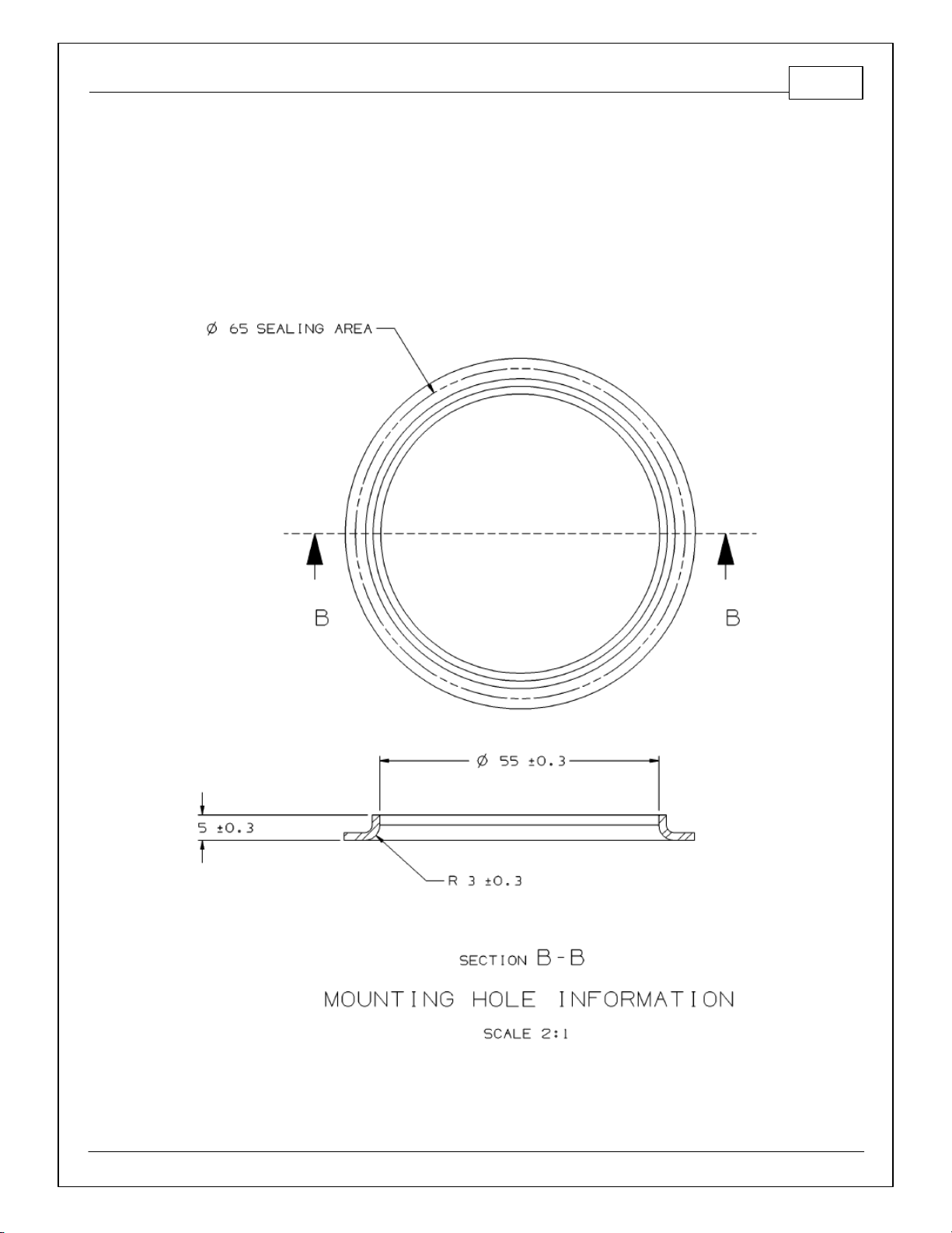
9
Grommet mounting hole requirem ents
grommet to separate engine compartment connections from vehicle cabin connections.
The main power and ground feeds (R1-R4) are designed with a long branch that can be
used to route to a trunk mounted battery. They include a heavy duty, serrated ring
terminal and should only be modified if absolutely necessary.
© 2014 AEM Performance Electronics
Page 10
AEM Infinity Harness Manuals10
3805 - Infinity Pinout Universal V8
Default functions are listed in parentheses
C1
Infinity Connector C1
73 Way F Receptacle 0.64 2.8 Series Sealed (GY)
Pin
Wire Color
Gauge
Destination
123
C1-1
--- C1-2
GRN20C8-1
LowsideSwitch_5
C1-3
ORG/RED
20
C11-5
LowsideSwitch_6
C1-4
WHT
18
C13-4
UEGO1_Heat
C1-5
GRN
20
C13-2
UEGO1_IA
C1-6
RED
20
C13-6
UEGO1_IP
C1-7
BLK
20
C13-1
UEGO1_UN
C1-8
ORN
20
C13-5
UEGO1_VM
C1-9
RED
20
C14-2
Flash_Enable
C1-10
RED20P1-8
+12V_R8C_CPU (Perm Power)
C1-11
DK GRN/WHT
20
C5-4
Coil4
C1-12
LT BLU
20
C5-3
Coil3
C1-13
RED/WHT
20
C5-2
Coil2
C1-14
VIO20C5-1
Coil1
C1-15
LT BLU/WHT
20
C5-10
Coil6
C1-16
DK GRN
20
C5-9
Coil5
C1-17
VIO
20
P1-37
LowsideSwitch_2 (Coolant Fan 1 Control)
C1-18
VIO/BLK
20
C8-3
LowsideSwitch_3 (MIL Output)
C1-19
BLK/WHT
20S2
AGND_1 (Analog Sensor Ground)
C1-20
BLK/WHT
20
C10-2
AGND_1 (Analog Sensor Ground)
C1-21
WHT
20
C10-1
Crank Position Sensor (Hall Effect)
C1-22
GRN
20
C10-3
Camsha ft Position Sensor 1 (Hall Effect)
C1-23
--- C1-24
--- C1-25
DK BLU/RED
20
C8-2
Digital_In_4 (Vehicle Speed Sensor Hall Effect)
C1-26
BLK/RED
20
C8-8
Digital_In_5 (Flex Fuel Sensor)
Auxiliary Connectors
The kit includes 2 optional connector kits that mate with connectors labeled Aux1 and
Aux2 on the main harness trunk. See the 3805 Core Harness Pinout section for details
on available functions. All default functions are listed in parentheses. Many are reassignable through the setup wizard interface.
83805 Core Harness Pinouts
© 2014 AEM Performance Electronics
Page 11
11
C1-27
--- C1-28
--- C1-29
YEL/WHT
20
P1-1
+12V_Relay_Cntrl (Lowside switch output)
C1-30
BLK20S1
Battery Ground
C1-31
GRN20C4-2
AEMNet CANL
C1-32
WHT
20
C4-1
AEMNet CANH
C1-33
WHT/RED
20
C8-4
LowsideSwitch_1 (Boost Control Soleonoid)
C1-34
VIO/WHT
20
P1-13
LowsideSwitch_0 (Fuel Pump)
C1-35
DK BLU
20F2 Analog_In_7 (Throttle Position Sensor)
C1-36
LT GRN
20F1
Analog_In_8 (MAP Sensor)
C1-37
GRN/BLU
20F3
Analog_In_9 (Fuel Pressure Sensor)
C1-38
BLU/BRN
20
C8-7
Analog_In_10 (Baro Sensor)
C1-39
BRN/ORG
20
C8-5
Analog_In_11 (Shift Switch Input)
C1-40
LT GRN
20
C8-6
Analog_In_12 (Mode Switch)
C1-41
GRY20S3
+5V_Out_1 (Analog Sensor Power)
C1-42
ORG
20
C10-5
+5V_Out_1 (Analog Sensor Power)
C1-43
--- C1-44
--- C1-45
BLK
22
C10-7
Crank Position (VR+)
C1-46
RED
22
C10-8
Crank Position (VR-)
C1-47
WHT
22
C10-9
Cam1 Position (VR-)
C1-48
GRN
22
C10-10
Cam1 Position (VR+)
C1-49
--- C1-50
--- C1-51
--- C1-52
--- C1-53
--- C1-54
--- C1-55
BLK20S7
Battery Ground
C1-56
YEL/BLK
20
C6-10
Injector 6
C1-57
BLU/RED
20
C6-9
Injector 5
C1-58
LT BLU/BLK
20
C6-4
Injector 4
C1-59
PNK/BLK
20
C6-3
Injector 3
C1-60
BLK20C16-L
Battery Ground
C1-61
RED20C3-G
Fused +12V Power from Relay
C1-62
LT GRN/BLK
20
C6-2
Injector 2
C1-63
BLU20C6-1
Injector 1
© 2014 AEM Performance Electronics
Page 12

AEM Infinity Harness Manuals12
C1-64
RED20C3-L
Fused +12V Power from Relay
C1-65
PNK/WHT
20
P1-27
Fused +12V Ignition Switch
C1-66
YEL20F6
Analog_In_Temp_1 (Coolant Temp Sensor)
C1-67
TAN20F5
Analog_In_Temp_2 (Air Temp Sensor)
C1-68
--- C1-69
LT GRN/WHT
20
C11-1
Stepper_2A
C1-70
LT BLU/WHT
20
C11-2
Stepper_1A
C1-71
LT GRN/BLK
20
C11-3
Stepper_2B
C1-72
LT BLU/BLK
20
C11-4
Stepper_1B
C1-73
BLK14C16-L
Battery Ground
C2
Infinity Connector C2
56 Way F Receptacle 0.64 2.8 Series Sealed (BU)
Pin
Wire Color
Gauge
Destination
123
C2-1
---
C2-2
---
C2-3
BLK
20
C16-L
Battery Ground
C2-4
RED/BLK
20
C6-11
Injector 7
C2-5
DK BLU/WHT
20
C6-12
Injector 8
C2-6
---
C2-7
---
C2-8
---
C2-9
RED
20
C3-M
Fused +12V Power from Relay
C2-10
---
C2-11
---
C2-12
ORG/GRN
20
C9-4
Analog_In_17 (A/C Request)
C2-13
---
C2-14
---
C2-15
---
C2-16
---
C2-17
---
C2-18
GRN
20F4
Analog_In_13 (Oil Pressure)
C2-19
DK BLU/RED
20
C9-3
Analog_In_14
C2-20
---
C2-21
---
C2-22
GRY
20
C9-7
+5V_Out_2 (Analog Sensor Power)
© 2014 AEM Performance Electronics
Page 13

13
C2-23
GRY
20F4 +5V_Out_2 (Analog Sensor Power)
C2-24
GRY
20F3 +5V_Out_2 (Analog Sensor Power)
C2-25
WHT
22
C7-1
VR+_In_5 (Driven Rt Wheel VR+)
C2-26
BLK
22
C7-2
VR-_In_5 (Driven Rt Wheel VR-)
C2-27
WHT
22
C7-4
VR-_In_4 (Non Driven Rt Wheel VR-)
C2-28
BLK
22
C7-5
VR+_In_4 (Non Driven Rt Wheel VR+)
C2-29
ORG/WHT
20
C9-1
LowsideSwitch_9 (Tachometer Output)
C2-30
BLK/WHT
20
C5-5
AGND_2 (Analog Sensor Ground)
C2-31
BLK/WHT
20
C9-8
AGND_2 (Analog Sensor Ground)
C2-32
BLK/WHT
20S4 AGND_2 (Analog Sensor Ground)
C2-33
---
C2-34
RED/BLK
20
C9-5
Analog_In_21 (3 Step Enable)
C2-35
C2-36
C2-37
C2-38
BLK/WHT
20
C9-6
Digital_In_7 (Clutch Switch)
C2-39
BLK
20S5
Battery Ground
C2-40
BLK
20
C16-J
Battery Ground
C2-41
---
C2-42
---
C2-43
RED/GRN
20
C9-2
LowsideSwitch_8 (Engine Protect Warning Output)
C2-44
---
C2-45
ORG
20
C12-5
UEGO2_VM
C2-46
BLK
20
C12-1
UEGO2_UN
C2-47
RED
20
C12-6
UEGO2_IP
C2-48
GRN
20
C12-2
UEGO2_IA
C2-49
WHT
18
C12-4
UEGO_2_Heat
C2-50
RED
20
P1-8
Fused +12V_R8C_CPU (Perm Power)
C2-51
TAN
20
C5-11
Coil 7
C2-52
VIO/WHT
20
C5-12
Coil 8
C2-53
---
C2-54
---
C2-55
---
C2-56
---
C3
280 METRI-PACK 12F
© 2014 AEM Performance Electronics
Page 14

AEM Infinity Harness Manuals14
Pin
Wire Color
Gauge
Destination
123ARED
12
P1-2
Fused +12V Relay Power
B
RED
20
P1-22
Fused +12V Relay Power
C
RED
20
P1-34
Fused +12V Relay Power
D
RED
20
P1-46
Fused +12V Relay Power
E
RED
20
P1-48
Fused +12V Relay Power
F
RED
20
C11-6
Fused +12V Relay Power
G
RED
20
C1-61
Fused +12V Relay Power
H
RED
20F7
Fused +12V Relay Power
J
RED
22S6
Fused +12V Relay Power
K
BRN
20
C12-3
C13-3
Fused +12V Relay Power
L
RED
20
C1-64
Fused +12V Relay Power
M
RED
20
C2-9
Fused +12V Relay Power
C4
DTM Plug, 4 Way
Pin
Wire Color
Gauge
Destination
AEMNet
1231WHT
20
C1-32
AEMNet CANH
2
GRN
20
C1-31
AEMNet CANL
3
RED
22S6
Power Splice
4
BLK
22S1
Ground Splice
C5
DT Plug, 12 Way
Pin
Wire Color
Gauge
Destination
Coils
1231VIO
20
C1-14
Coil1
2
RED/WHT
20
C1-13
Coil2
3
LT BLU
20
C1-12
Coil3
4
DK GRN/WHT
20
C1-11
Coil4
5
BLK/WHT
20
C2-30
AGND_2 (Sensor Ground)
6
RED
14
C15-D
Fused +12V Relay Power
7
RED
14
C15-K
Fused +12V Relay Power
8
BLK
14
C16-M
Battery Ground
9
DK GRN
20
C1-16
Coil5
10
LT BLU/WHT
20
C1-15
Coil6
© 2014 AEM Performance Electronics
Page 15

15
11
TAN
20
C2-51
Coil7
12
VIO/WHT
20
C2-52
Coil8
C6
DT Receptacle, 12 Way
Pin
Wire Color
Gauge
Destination
Injectors
1231BLU
20
C1-63
Injector 1
2
LT GRN/BLK
20
C1-62
Injector 2
3
PNK/BLK
20
C1-59
Injector 3
4
LT BLU/BLK
20
C1-58
Injector 4
5
RED
18
C15-B
Fused +12V Relay Power
6
RED
18
C15-C
Fused +12V Relay Power
7
RED
18
C15-H
Fused +12V Relay Power
8
RED
18
C15-J
Fused +12V Relay Power
9
BLU/RED
20
C1-57
Injector 5
10
YEL/BLK
20
C1-56
Injector 6
11
RED/BLK
20
C2-4
Injector 7
12
DK BLU/WHT
20
C2-5
Injector 8
C7
DTM Receptacle, 6 Way
Pin
Wire Color
Gauge
Destination
WheelSpeeds
1231WHT
20
C2-25
VR+_In_5 (Driven Rt Wheel VR+)
2
BLK
20
C2-26
VR-_In_5 (Driven Rt Wheel VR-)
3
4
WHT
20
C2-27
VR-_In_4 (Non Driven Rt Wheel VR-)
5
BLK
20
C2-28
VR+_In_4 (Non Driven Rt Wheel VR+)
6
BLK
22S5
Shield Ground
C8
DTM Plug, 8 Way
Pin
Wire Color
Gauge
Destination
Aux2
1231GRN
20
C1-2
LowsideSwitch_5
2
DK BLU/RED
20
C1-25
Digital_In_4 (Vehicle Speed Sensor Hall Effect)
3
VIO/BLK
20
C1-18
LowsideSwitch_3 (MIL Output)
4
WHT/RED
20
C1-33
LowsideSwitch_1 (Boost Control Solenoid)
© 2014 AEM Performance Electronics
Page 16

AEM Infinity Harness Manuals16
5
ORG/WHT
20
C1-39
Analog_In_11 (Shift Switch Input)
6
RED/GRN
20
C1-40
Analog_In_12 (Mode Switch)
7
BLU/BRN
20
C1-38
Analog_In_10 (Baro Sensor)
8
BLK/RED
20
C1-26
Digital_In_5 (Flex Fuel Sensor)
C9
DTM Receptacle, 8 Way
Pin
Wire Color
Gauge
Destination
Aux1
1231ORG/WHT
20
C2-29
LowsideSwitch_9 (Tachometer Output)
2
LT GRN
20
C2-43
LowsideSwitch_8 (Engine Protect Warning Output)
3
DK BLU/RED
20
C2-19
Analog_In_14
4
ORG/GRN
20
C2-12
Analog_In_17 (A/C Request)
5
RED/BLK
20
C2-34
Analog_In_21 (3 Step Enable)
6
BLK/WHT
20
C2-38
Digital_In_7 (Clutch Switch)
7
GRY
20
C2-22
+5V_Out_2 (Analog Sensor Power)
8
BLK/WHT
20
C2-31
AGND_2 (Sensor Ground)
C10
DTM Receptacle, 12 Way
Pin
Wire Color
Gauge
Destination
Crank/Cam
1231WHITE
22
C1-21
Crank Position Sensor (Hall Effect)
2
BLK
22
C1-20
AGND_1 (Analog Sensor Ground)
3
GRN
22
C1-22
Camsha ft Position Sensor 1 (Hall Effect)
4
RED
22S6
Fused +12V Relay Power
5
ORG
22
C1-42
+5V_Out_1 (Analog Sensor Power)
6
7
BLK
22
C1-45
Crank Position (VR+)
8
RED
22
C1-46
Crank Position (VR-)
9
WHT
22
C1-47
Cam1 Position (VR-)
10
GRN
22
C1-48
Cam1 Position (VR+)
11
BLK
22S7
Shield Ground
12
C11
DTM Receptacle, 6 Way
Pin
Wire Color
Gauge
Destination
Idle
123
© 2014 AEM Performance Electronics
Page 17

17
1
LT GRN/WHT
20
C1-69
Stepper_2A
2
LT BLU/WHT
20
C1-70
Stepper_1A
3
LT GRN/BLK
20
C1-71
Stepper_2B
4
LT BLU/BLK
20
C1-72
Stepper_1B
5
ORG/RED
20
C1-3
LowsideSwitch_6 (PWM Idle)
6
RED
20
C3-F
Fused +12V Relay Power
C12
DTM Receptacle, 6 Way
Pin
Wire Color
Gauge
Destination
UEGO2
1231BLK
20
C2-46
UEGO2_UN
2
GRN
20
C2-48
UEGO2_IA
3
BRN
20
C3-K
Fused +12V Relay Power
4
WHT
18
C2-49
UEGO_2_Heat
5
ORG
20
C2-45
UEGO2_VM
6
RED
20
C2-47
UEGO2_IP
C13
DTM Receptacle, 6 Way
Pin
Wire Color
Gauge
Destination
UEGO1
1231BLK
20
C1-7
UEGO1_UN
2
GRN
20
C1-5
UEGO1_IA
3
BRN
20
C3-K
Fused +12V Relay Power
4
WHT
18
C1-4
UEGO1_Heat
5
ORN
20
C1-8
UEGO1_VM
6
RED
20
C1-6
UEGO1_IP
C14
DTM Receptacle, 2 Way
Pin
Wire Color
Gauge
Destination
Flash
1231RED
20
P1-8
Fused +12V Battery Power
2
RED
20
C1-9
Flash_Enable
C15
280 METRI-PACK 12F
Pin
Wire Color
Gauge
Destination
© 2014 AEM Performance Electronics
Page 18

AEM Infinity Harness Manuals18
123ARED
12
P1-40
Fused +12V Relay Power
B
RED
18
C6-5
Fused +12V Relay Power
C
RED
18
C6-6
Fused +12V Relay Power
D
RED
14
C5-6
Fused +12V Relay Power
E
F
G
RED
12
P1-26
Fused +12V Relay Power
H
RED
18
C6-7
Fused +12V Relay Power
J
RED
18
C6-8
Fused +12V Relay Power
K
RED
14
C5-7
Fused +12V Relay Power
L
M
C16
280 METRI-PACK 12F
Pin
Wire Color
Gauge
Destination
123ARED
12R3
Battery Power
B
RED
12R4
Battery Power
C
RED
12
P1-7
Battery Power
D
RED
12
P1-15
Battery Power
E
RED
12
P1-23
Battery Power
F
RED
12
P1-16
Battery Power
G
BLK
12R1
Battery Ground
H
BLK
12R2
Battery Ground
J
BLK
20, 22, 22
C2-40
P1-39
S5
Battery Ground
K
BLK
22, 22, 22
S1
P1-25
S7
Battery Ground
L
BLK
20, 20, 14
C1-60
C2-3
C1-
73
Battery Ground
M
BLK
14
C5-8
Battery Ground
P1
Power Distribution Module, PDM-T3AA1
Pin
Wire Color
Gauge
Destination
1231YEL/WHT
20
C1-29
+12V_Relay_Cntrl (Lowside switch output)
2
RED
12
C3-A
Fused +12V Relay Power
3
RED
12, 22
P1-9
P1-10 Fused +12V Battery Power
© 2014 AEM Performance Electronics
Page 19

19
4
RED
20R4
+12V Battery Power
5
6
7
RED
12
C16-C
+12V Battery Power
8
RED
20, 20, 20
C1-10
C2-50
C14-
1
Fused +12V Battery Power
9
RED
12
P1-3
Fused +12V Battery Power
10
RED
22
P1-3
Fused +12V Battery Power
11
RED
12
P1-33
Fused +12V Battery Power
12
RED
12
P1-21
Fused +12V Battery Power
13
VIO/WHT
20
C1-34
LowsideSwitch_0 (Fuel Pump)
14
RED/GRN
12F7 Fused +12V Power for Fuel Pump
15
RED
12
C16-D
+12V Battery Power
16
RED
12
C16-F
+12V Battery Power
17
18
19
RED
12
P1-47
Fused +12V Battery Power
20
RED
12
P1-45
Fused +12V Battery Power
21
RED
12
P1-12
Fused +12V Battery Power
22
RED
20
C3-B
Fused +12V Battery Power
23
RED
12
C16-E
+12V Battery Power
24
RED
12R3
+12V Battery Power
25
BLACK
20
C16-K
Battery Ground
26
RED
12
C15-G
Fused +12V Battery Power for Inj. And Coils
27
PNK/WHT
20
C1-65
Fused +12V Switched Ignition Power
28
29
30
31
PNK/WHT
22F7
+12V Switched Ignition Power
32
33
RED
12
P1-11
Fused +12V Battery Power
34
RED
20
C3-C
Fused +12V Battery Power
35
36
37
VIO
20
C1-17
LowsideSwitch_2 (Coolant Fan 1 Control)
38
RED/BLU
12F7 Fused +12V Power for Coolant Fan 1
39
BLK
22
C16-J
Battery Ground
© 2014 AEM Performance Electronics
Page 20

AEM Infinity Harness Manuals20
40
RED
12
C15-A
Fused +12V Battery Power for Inj. And Coils
41
42
43
44
45
RED
12
P1-20
Fused +12V Battery Power
46
RED
20
C3-D
Fused +12V Relay Power
47
RED
12
P1-19
Fused +12V Battery Power
48
RED
20
C3-E
Fused +12V Relay Power
F1
Flying Leads
Pin
Wire Color
Gauge
Destination
MAP
123 LT GRN
20
C1-36
Analog_In_8 (MAP Sensor)
BLK/WHT
22S2 AGND_1 (Analog Sensor Ground)
GRY
22S3 +5V_Out_1 (Analog Sensor Power)
F2
Flying Leads
Pin
Wire Color
Gauge
Destination
Throttle
123 DK BLU
20
C1-35
Analog_In_7 (Throttle Position Sensor)
BLK/WHT
22S2 AGND_1 (Analog Sensor Ground)
GRY
22S3 +5V_Out_1 (Analog Sensor Power)
F3
Flying Leads
Pin
Wire Color
Gauge
Destination
FuelPress
123 GRN/BLU
20
C1-37
Analog_In_9 (Fuel Pressure Sensor)
BLK/WHT
22S2 AGND_1 (Analog Sensor Ground)
GRY
20
C2-24
+5V_Out_2 (Analog Sensor Power)
F4
Flying Leads
Pin
Wire Color
Gauge
Destination
OilPress
123 GRN
20
C2-18
Analog_In_13 (Oil Pressure)
© 2014 AEM Performance Electronics
Page 21

21
BLK/WHT
22S2 AGND_1 (Analog Sensor Ground)
GRY
20
C2-23
+5V_Out_2 (Analog Sensor Power)
F5
Flying Leads
Pin
Wire Color
Gauge
Destination
AirTemp
123 TAN
20
C1-67
Analog_In_Temp_2 (Air Temp Sensor)
BLK/WHT
22S4 AGND_2 (Analog Sensor Ground)
F6
Flying Leads
Pin
Wire Color
Gauge
Destination
CoolantTemp
123 YEL
20
C1-66
Analog_In_Temp_1 (Coolant Temp Sensor)
BLK/WHT
22S4 AGND_2 (Analog Sensor Ground)
F7
Flying Leads
Pin
Wire Color
Gauge
Destination
123 RED
20
C3-H
12V ACC. OUT
RED/BLU
12
P1-38
FAN1
RED/GRN
12
P1-14
FUELPUMP1
PNK/WHT
22
P1-31
IGNSWT
S1
Splice
Pin
Wire Color
Gauge
Destination
123InBLK
22
C16-K
Battery Ground
Out
BLK
20
C1-30
Battery Ground
Out
BLK
22
C4-4
Battery Ground
S2
Splice
Pin
Wire Color
Gauge
Destination
123InBLK/WHT
20
C1-19
AGND_1 (Analog Sensor Ground)
Out
BLK/WHT
22F1 AGND_1 (Analog Sensor Ground)
© 2014 AEM Performance Electronics
Page 22

AEM Infinity Harness Manuals22
Out
BLK/WHT
22F2 AGND_1 (Analog Sensor Ground)
Out
BLK/WHT
22F3 AGND_1 (Analog Sensor Ground)
Out
BLK/WHT
22F4 AGND_1 (Analog Sensor Ground)
S3
Splice
Pin
Wire Color
Gauge
Destination
123InGRY
20
C1-41
+5V_Out_1 (Analog Sensor Power)
Out
GRY
22F1 +5V_Out_1 (Analog Sensor Power)
Out
GRY
22F2 +5V_Out_1 (Analog Sensor Power)
S4
Splice
Pin
Wire Color
Gauge
Destination
123InBLK/WHT
20
C2-32
AGND_2 (Analog Sensor Ground)
Out
BLK/WHT
20F5 AGND_2 (Analog Sensor Ground)
Out
BLK/WHT
20F6 AGND_2 (Analog Sensor Ground)
S5
Splice
Pin
Wire Color
Gauge
Destination
123InBLK
22
C16-J
Battery Ground
Out
BLK
20
C2-39
Battery Ground
Out
BLK
22
C7-6
Battery Ground
S6
Splice
Pin
Wire Color
Gauge
Destination
123InRED
22
C3-J
Fused +12V Relay Power
Out
RED
22
C4-3
Fused +12V Relay Power
Out
RED
22
C10-4
Fused +12V Relay Power
S7
Splice
Pin
Wire Color
Gauge
Destination
123InBLK
22
C16-K
Battery Ground
© 2014 AEM Performance Electronics
Page 23

23
Out
BLK
20
C1-55
Battery Ground
Out
BLK
22
C10-
11
Battery Ground
R1
Ring Terminal
Pin
Wire Color
Gauge
Destination
Batt-
123 BLK
12
C16-G
Battery Ground
R2
Ring Terminal
Pin
Wire Color
Gauge
Destination
Batt-
123 BLK
12
C16-H
Battery Ground
R3
Ring Terminal
Pin
Wire Color
Gauge
Destination
Batt+
123 RED
12,12
C16-A
P1-24
+12V Battery Power
R4
Ring Terminal
Pin
Wire Color
Gauge
Destination
Batt+
123 RED
12, 20
C16-B
P1-4
+12V Battery Power
© 2014 AEM Performance Electronics
Page 24

AEM Infinity Harness Manuals24
Infinity Pin
Hrdwr Ref.
Hardware Specification
Notes
C1-1
LowsideSwitch_4
Lowside switch, 4A max, NO
internal flyback diode.
Normally used as A/C Relay Control output.
C1-2
LowsideSwitch_5
Lowside switch, 4A max with
internal flyback diode. Inductive
load should NOT have full time
power.
See Setup Wizard Page "LowSide Assignment
Tables" for output assignment and 2D table
"LS5_Duty [%]" for activation.
C1-3
LowsideSwitch_6
Lowside switch, 4A max with
internal flyback diode. Inductive
load should NOT have full time
power.
See Setup Wizard Page "LowSide Assignment
Tables" for output assignment and 2D table
"LS6_Duty [%]" for activation.
C1-4
UEGO 1 Heat
Bosch UEGO controller
Lowside switch for UEGO heater control. Connect
to pin 4 of Bosch UEGO sensor. NOTE that pin 3 of
the Sensor is heater (+) and must be power by a
fused/switched 12V supply.
C1-5
UEGO 1 IA
Trim Current signal. Connect to pin 2 of Bosch
UEGO sensor
C1-6
UEGO 1 IP
Pumping Current signal. Connect to pin 6 of Bosch
UEGO sensor
C1-7
UEGO 1 UN
Nernst Voltage signal. Connect to pin 1 of Bosch
UEGO sensor
C1-8
UEGO 1 VM
Virtual Ground signal. Connect to pin 5 of Bosch
UEGO sensor.
C1-9
Flash_Enable
10K pulldown
Not usually needed for automatic firmware
updates through Infinity Tuner. If connection
errors occur during update, connect 12 volts to
this pin before proceeding with upgrade.
Disconnect the 12 volts signal after the update.
C1-10
+12V_R8C_CPU
Dedicated power management CPU
Full time battery power. MUST be powered before
the ignition switch input is triggered (See C1-65).
C1-11
Coil 4
25 mA max source current
0-5V Falling edge fire. DO NOT connect directly to
coil primary. Must use an ignitor OR CDI that
accepts a FALLING edge fire signal.
C1-12
Coil 3
25 mA max source current
0-5V Falling edge fire. DO NOT connect directly to
coil primary. Must use an ignitor OR CDI that
accepts a FALLING edge fire signal.
93805 Core Harness Schematic
A schematic for the universal core harness is included HERE
10Infinity-8/10/12 ECU Pinout
© 2014 AEM Performance Electronics
Page 25

25
Infinity Pin
Hrdwr Ref.
Hardware Specification
Notes
C1-13
Coil 2
25 mA max source current
0-5V Falling edge fire. DO NOT connect directly to
coil primary. Must use an ignitor OR CDI that
accepts a FALLING edge fire signal.
C1-14
Coil 1
25 mA max source current
0-5V Falling edge fire. DO NOT connect directly to
coil primary. Must use an ignitor OR CDI that
accepts a FALLING edge fire signal.
C1-15
Coil 6
25 mA max source current
0-5V Falling edge fire. DO NOT connect directly to
coil primary. Must use an ignitor OR CDI that
accepts a FALLING edge fire signal.
C1-16
Coil 5
25 mA max source current
0-5V Falling edge fire. DO NOT connect directly to
coil primary. Must use an ignitor OR CDI that
accepts a FALLING edge fire signal.
C1-17
LowsideSwitch_2
Lowside switch, 4A max, NO
internal flyback diode.
See Setup Wizard Pages "User GPOs" for activation
criteria and "LowSide Assignment Tables" for
output assignment
C1-18
LowsideSwitch_3
Lowside switch, 4A max with
internal flyback diode. Inductive
load should NOT have full time
power.
Normally used as MIL output. 'See Wizard page
"LowSide Assignment Tables" for output
assignment.
C1-19
AGND_1
Dedicated analog ground
Analog 0-5V sensor ground
C1-20
AGND_1
Dedicated analog ground
Analog 0-5V sensor ground
C1-21
Crankshaft Position
Sensor Hall
10K pullup to 12V. Will work with
ground or floating switches.
See Setup Wizard page Cam/Crank for options.
C1-22
Camsha ft Position
Sensor 1 Hall
10K pullup to 12V. Will work with
ground or floating switches.
See Setup Wizard page Cam/Crank for options.
C1-23
Digital_In_2
10K pullup to 12V. Will work with
ground or floating switches.
See Setup Wizard page Cam/Crank for options.
C1-24
Digital_In_3
10K pullup to 12V. Will work with
ground or floating switches.
See Setup Wizard page Turbo Speed for calibration
constant.
C1-25
Digital_In_4
10K pullup to 12V. Will work with
ground or floating switches.
See Setup Wizard page Vehicle Speed for
calibration constant.
© 2014 AEM Performance Electronics
Page 26

AEM Infinity Harness Manuals26
Infinity Pin
Hrdwr Ref.
Hardware Specification
Notes
C1-26
Digital_In_5
10K pullup to 12V. Will work with
ground or floating switches.
See channel FlexDigitalIn [Hz] for raw frequency
input data.
C1-27
Knock Sensor 1
Dedicated knock signal processor
See Setup Wizard page Knock Setup for options.
C1-28
Knock Sensor 2
Dedicated knock signal processor
See Setup Wizard page Knock Setup for options.
C1-29
+12V_Relay_Control
0.7A max ground sink for external
relay control
Will activate at key on and at key off according to
the configuration settings.
C1-30
Power Ground
Power Ground
Connect directly to battery ground
C1-31
CANL_Aout
Dedicated High Speed CAN
Transceiver
Recommend twisted pair (one twist per 2") with
terminating resistor. Contact AEM for additional
information.
C1-32
CANH_Aout
Dedicated High Speed CAN
Transceiver
Recommend twisted pair (one twist per 2") with
terminating resistor. Contact AEM for additional
information.
C1-33
LowsideSwitch_1
Lowside switch, 4A max with
internal flyback diode. Inductive
load should NOT have full time
power.
See Setup Wizard page Boost Control for options.
Monitor BoostControl [%] channel for output
state.
C1-34
LowsideSwitch_0
Lowside switch, 4A max, NO
internal flyback diode.
Switched ground. Will prime for 2 seconds at key
on and activate if RPM > 0.
C1-35
Analog_In_7
12 bit A/D, 100K pullup to 5V
0-5V analog signal. Use +5V Out pins as power
supply and Sensor Ground pins as the low
reference. Do not connect signals referenced to
+12V as this can permanently damage the ECU.
See the Setup Wizard Set Throttle Range page for
automatic min/max calibration.
C1-36
Analog_In_8
12 bit A/D, 100K pullup to 5V
0-5V analog signal. Use +5V Out pins as power
supply and Sensor Ground pins as the low
reference. Do not connect signals referenced to
+12V as this can permanently damage the ECU.
See the Setup Wizard Set Manifold Pressure page
for setup and calibration.
© 2014 AEM Performance Electronics
Page 27

27
Infinity Pin
Hrdwr Ref.
Hardware Specification
Notes
C1-37
Analog_In_9
12 bit A/D, 100K pullup to 5V
0-5V analog signal. Use +5V Out pins as power
supply and Sensor Ground pins as the low
reference. Do not connect signals referenced to
+12V as this can permanently damage the ECU.
See the Setup Wizard Fuel Pressure page for setup
and calibra tion.
C1-38
Analog_In_10
12 bit A/D, 100K pullup to 5V
0-5V analog signal. Use +5V Out pins as power
supply and Sensor Ground pins as the low
reference. Do not connect signals referenced to
+12V as this can permanently damage the ECU.
See the Setup Wizard Barometric Pressure page
for setup and calibration.
C1-39
Analog_In_11
12 bit A/D, 100K pullup to 5V
0-5V analog signal. Use +5V Out pins as power
supply and Sensor Ground pins as the low
reference. Do not connect signals referenced to
+12V as this can permanently damage the ECU.
Normally used as Shift Switch input.
C1-40
Analog_In_12
12 bit A/D, 100K pullup to 5V
0-5V analog signal. Use +5V Out pins as power
supply and Sensor Ground pins as the low
reference. Do not connect signals referenced to
+12V as this can permanently damage the ECU.
Normally used as Mode Switch input.
C1-41
+5V_Out_1
Regulated, fused +5V supply for
sensor power
Analog sensor power
C1-42
+5V_Out_1
Regulated, fused +5V supply for
sensor power
Analog sensor power
C1-43
HighsideSwitch_1
0.7A max, High Side Solid State
Relay
See Setup Wizard page 'HighSide Assigment
Tables' for configuration options.
C1-44
HighsideSwitch_0
0.7A max, High Side Solid State
Relay
See Setup Wizard page 'HighSide Assigment
Tables' for configuration options.
C1-45
Crankshaft Position
Sensor VR+
Differential Variable Reluctance
Zero Cross Detection
See Setup Wizard page Cam/Crank for options.
C1-46
Crankshaft Position
Sensor VR-
See Setup Wizard page Cam/Crank for options.
C1-47
Camsha ft Position
Sensor 1 VR-
Differential Variable Reluctance
Zero Cross Detection
See Setup Wizard page Cam/Crank for options.
C1-48
Camsha ft Position
Sensor 1 VR+
See Setup Wizard page Cam/Crank for options.
© 2014 AEM Performance Electronics
Page 28

AEM Infinity Harness Manuals28
Infinity Pin
Hrdwr Ref.
Hardware Specification
Notes
C1-49
VR+_In_2
Differential Variable Reluctance
Zero Cross Detection
See Non Driven Wheel Speed Calibration in the
Setup Wizard Vehicle Speed page.
C1-50
VR-_In_2
C1-51
VR-_In_3
Differential Variable Reluctance
Zero Cross Detection
See Driven Wheel Speed Calibration in the Setup
Wizard Vehicle Speed page.
C1-52
VR+_In_3
C1-53
DBW1 Motor -
5.0A max Throttle Control Hbridge
Drive
+12V to close.
C1-54
DBW1 Motor +
5.0A max Throttle Control Hbridge
Drive
+12V to open.
C1-55
Power Ground
Power Ground
Connect directly to battery ground
C1-56
Injector 6
Saturated or peak and hold, 3A max
continuous
Injector 6
C1-57
Injector 5
Saturated or peak and hold, 3A max
continuous
Injector 5
C1-58
Injector 4
Saturated or peak and hold, 3A max
continuous
Injector 4
C1-59
Injector 3
Saturated or peak and hold, 3A max
continuous
Injector 3
C1-60
Power Ground
Power Ground
Connect directly to battery ground
C1-61
+12V
12 volt power from relay
12 volt power from relay. Relay must be
controlled by +12V Relay Control signal, pin C1-29
above.
C1-62
Injector 2
Saturated or peak and hold, 3A max
continuous
Injector 2
C1-63
Injector 1
Saturated or peak and hold, 3A max
continuous
Injector 1
C1-64
+12V
12 volt power from relay
12 volt power from relay. Relay must be
controlled by +12V Relay Control signal pin C1-29
above.
C1-65
+12V_SW
10K pulldown
Full time battery power must be available at C110 before this input is triggered.
C1-66
Analog_In_Temp_1
12 bit A/D, 2.49K pullup to 5V
See "Coolant Temperature" Setup Wizard for
selection.
© 2014 AEM Performance Electronics
Page 29

29
Infinity Pin
Hrdwr Ref.
Hardware Specification
Notes
C1-67
Analog_In_Temp_2
12 bit A/D, 2.49K pullup to 5V
See "Air Temperature" Setup Wizard for selection.
C1-68
Analog_In_Temp_3
12 bit A/D, 2.49K pullup to 5V
Normally used for Oil Temp input.
C1-69
Stepper_2A
Automotive, Programmable
Stepper Driver, up to 28V and ±1.4A
Be sure that each internal coil of the stepper
motor are properly paired with the 1A/1B and
2A/2B ECU outputs. Supports Bi-Polar stepper
motors only.
C1-70
Stepper_1A
Automotive, Programmable
Stepper Driver, up to 28V and ±1.4A
Be sure that each internal coil of the stepper
motor are properly paired with the 1A/1B and
2A/2B ECU outputs. Supports Bi-Polar stepper
motors only.
C1-71
Stepper_2B
Automotive, Programmable
Stepper Driver, up to 28V and ±1.4A
Be sure that each internal coil of the stepper
motor are properly paired with the 1A/1B and
2A/2B ECU outputs. Supports Bi-Polar stepper
motors only.
C1-72
Stepper_1B
Automotive, Programmable
Stepper Driver, up to 28V and ±1.4A
Be sure that each internal coil of the stepper
motor are properly paired with the 1A/1B and
2A/2B ECU outputs. Supports Bi-Polar stepper
motors only.
C1-73
Power Ground
Power Ground
Connect directly to battery ground
C2-1
DBW2 Motor +
5.0A max Throttle Control Hbridge
Drive
+12V to open.
C2-2
DBW2 Motor -
5.0A max Throttle Control Hbridge
Drive
+12V to close.
C2-3
Power Ground
Power Ground
Connect directly to battery ground
C2-4
Injector 7
Saturated or peak and hold, 3A max
continuous
Injector 7
C2-5
Injector 8
Saturated or peak and hold, 3A max
continuous
Injector 8
C2-6
Injector 9
Saturated or peak and hold, 3A max
continuous
Injector 9.
C2-7
Injector 10
Saturated or peak and hold, 3A max
continuous
Injector 10.
C2-8
Power Ground
Power Ground
Connect directly to battery ground.
C2-9
+12V
12 volt power from relay
12 volt power from relay. Relay must be
controlled by +12V Relay Control signal, pin C1-29
above.
C2-10
Injector 11
Saturated or peak and hold, 3A max
continuous
Not used
© 2014 AEM Performance Electronics
Page 30

AEM Infinity Harness Manuals30
Infinity Pin
Hrdwr Ref.
Hardware Specification
Notes
C2-11
Injector 12
Saturated or peak and hold, 3A max
continuous
Not used
C2-12
Analog_In_17
12 bit A/D, 100K pullup to 5V
0-5V analog signal. Use +5V Out pins as power
supply and Sensor Ground pins as the low
reference. Do not connect signals referenced to
+12V as this can permanently damage the ECU.
Normally used as A/C Analog Request input.
C2-13
Analog_In_18
12 bit A/D, 100K pullup to 5V
0-5V analog signal. Use +5V Out pins as power
supply and Sensor Ground pins as the low
reference. Do not connect signals referenced to
+12V as this can permanently damage the ECU.
Normally used as DBW APP1.
C2-14
Analog_In_19
12 bit A/D, 100K pullup to 5V
0-5V analog signal. Use +5V Out pins as power
supply and Sensor Ground pins as the low
reference. Do not connect signals referenced to
+12V as this can permanently damage the ECU.
Normally used as DBW APP2.
C2-15
Analog_In_Temp_4
12 bit A/D, 2.49K pullup to 5V
Normally used as Charge Out Temperature input.
C2-16
Analog_In_Temp_5
12 bit A/D, 2.49K pullup to 5V
Normally used as Airbox Temperature input.
C2-17
Analog_In_Temp_6
12 bit A/D, 2.49K pullup to 5V
Normally used as Fuel Temperature input.
C2-18
Analog_In_13
12 bit A/D, 100K pullup to 5V
0-5V analog signal. Use +5V Out pins as power
supply and Sensor Ground pins as the low
reference. Do not connect signals referenced to
+12V as this can permanently damage the ECU.
See Setup Wizard Oil Pressure page for setup
options. See OilPressure [psig] for channel data.
C2-19
Analog_In_14
12 bit A/D, 100K pullup to 5V
0-5V analog signal. Use +5V Out pins as power
supply and Sensor Ground pins as the low
reference. Do not connect signals referenced to
+12V as this can permanently damage the ECU.
© 2014 AEM Performance Electronics
Page 31

31
Infinity Pin
Hrdwr Ref.
Hardware Specification
Notes
C2-20
Analog_In_15
12 bit A/D, 100K pullup to 5V
0-5V analog signal. Use +5V Out pins as power
supply and Sensor Ground pins as the low
reference. Do not connect signals referenced to
+12V as this can permanently damage the ECU.
Normally used as Exhaust Back Pressure input.
C2-21
Analog_In_16
12 bit A/D, 100K pullup to 5V
0-5V analog signal. Use +5V Out pins as power
supply and Sensor Ground pins as the low
reference. Do not connect signals referenced to
+12V as this can permanently damage the ECU.
Normally used as DBW1_TPSB input.
C2-22
+5V_Out_2
Regulated, fused +5V supply for
sensor power
Analog sensor power
C2-23
+5V_Out_2
Regulated, fused +5V supply for
sensor power
Analog sensor power
C2-24
+5V_Out_2
Regulated, fused +5V supply for
sensor power
Analog sensor power
C2-25
VR+_In_5
Differential Variable Reluctance
Zero Cross Detection
See Driven Wheel Speed Calibration in the Setup
Wizard Vehicle Speed page.
C2-26
VR-_In_5
C2-27
VR-_In_4
Differential Variable Reluctance
Zero Cross Detection
See Non Driven Wheel Speed Calibration in the
Setup Wizard Vehicle Speed page.
C2-28
V R+_In_4
C2-29
LowsideSwitch_9
Lowside switch, 4A max with
internal flyback diode, 2.2K 12V
pullup. Inductive load should NOT
have full time power.
See Setup Wizard page Tacho for configuration
options.
C2-30
AGND_2
Dedicated analog ground
Analog 0-5V sensor ground
C2-31
AGND_2
Dedicated analog ground
Analog 0-5V sensor ground
C2-32
AGND_2
Dedicated analog ground
Analog 0-5V sensor ground
© 2014 AEM Performance Electronics
Page 32

AEM Infinity Harness Manuals32
Infinity Pin
Hrdwr Ref.
Hardware Specification
Notes
C2-33
Analog_In_20
12 bit A/D, 100K pullup to 5V
0-5V analog signal. Use +5V Out pins as power
supply and Sensor Ground pins as the low
reference. Do not connect signals referenced to
+12V as this can permanently damage the ECU.
C2-34
Analog_In_21
12 bit A/D, 100K pullup to 5V
0-5V analog signal. Use +5V Out pins as power
supply and Sensor Ground pins as the low
reference. Do not connect signals referenced to
+12V as this can permanently damage the ECU.
Normally used as 3 Step Enable Switch input.
C2-35
Analog_In_22
12 bit A/D, 100K pullup to 5V
0-5V analog signal. Use +5V Out pins as power
supply and Sensor Ground pins as the low
reference. Do not connect signals referenced to
+12V as this can permanently damage the ECU.
Normally used as USB Logging Request input.
C2-36
Analog_In_23
12 bit A/D, 100K pullup to 5V
0-5V analog signal. Use +5V Out pins as power
supply and Sensor Ground pins as the low
reference. Do not connect signals referenced to
+12V as this can permanently damage the ECU.
Normally used as Charge Out Pressure input.
C2-37
Digital_In_6
No pullup. Will work with TTL
signals.
Input can be assigned to different pins. See Setup
Wizard page Input Function Assignments for input
mapping options.
C2-38
Digital_In_7
No pullup. Will work with TTL
signals.
See ClutchSwitch 1-axis table for setup options.
Input can be assigned to different pins. See Setup
Wizard page Input Function Assignments for input
mapping options.
C2-39
Power Ground
Power Ground
Connect directly to battery ground
C2-40
Power Ground
Power Ground
Connect directly to battery ground
C2-41
CanH_Bout
Dedicated High Speed CAN
Transceiver
Not used
C2-42
CanL_Bout
Dedicated High Speed CAN
Transceiver
Not used
© 2014 AEM Performance Electronics
Page 33

33
Infinity Pin
Hrdwr Ref.
Hardware Specification
Notes
C2-43
LowsideSwitch_8
Lowside switch, 4A max with
internal flyback diode. Inductive
load should NOT have full time
power.
Activates if any of the following flags are true:
OilPressProtectOut, LeanProtectOut,
CoolantProtect. Output can be assigned to other
functions. See Setup Wizard page LowSide
Assignment Tables for additional options.
C2-44
LowsideSwitch_7
Lowside switch, 4A max with
internal flyback diode. Inductive
load should NOT have full time
power.
Normally used as Spare GPO1 output.
C2-45
UEGO 2 VM
Bosch UEGO Controller
Virtual Ground signal. Connect to pin 5 of Bosch
UEGO sensor.
C2-46
UEGO 2 UN
Nernst Voltage signal. Connect to pin 1 of Bosch
UEGO sensor
C2-47
UEGO 2 IP
Pumping Current signal. Connect to pin 6 of Bosch
UEGO sensor
C2-48
UEGO 2 IA
Trim Current signal. Connect to pin 2 of Bosch
UEGO sensor
C2-49
UEGO 2 HEAT
Lowside switch for UEGO heater control. Connect
to pin 4 of Bosch UEGO sensor. NOTE that pin 3 of
the Sensor is heater (+) and must be power by a
fused/switched 12V supply.
C2-50
+12V_R8C_CPU
Dedicated power management CPU
Optional full time battery power. MUST be
powered before the ignition switch input is
triggered (See C1-65).
C2-51
Coil 7
25 mA max source current
0-5V Falling edge fire. DO NOT connect directly to
coil primary. Must use an ignitor OR CDI that
accepts a FALLING edge fire signal.
C2-52
Coil 8
25 mA max source current
0-5V Falling edge fire. DO NOT connect directly to
coil primary. Must use an ignitor OR CDI that
accepts a FALLING edge fire signal.
C2-53
Coil 9
25 mA max source current
0-5V Falling edge fire. DO NOT connect directly to
coil primary. Must use an ignitor OR CDI that
accepts a FALLING edge fire signal.
C2-54
Coil 10
25 mA max source current
0-5V Falling edge fire. DO NOT connect directly to
coil primary. Must use an ignitor OR CDI that
accepts a FALLING edge fire signal.
© 2014 AEM Performance Electronics
Page 34

AEM Infinity Harness Manuals34
Infinity Pin
Hrdwr Ref.
Hardware Specification
Notes
C2-55
Highside Fuel Pump
Switch
Highside switch, 0.7A max, Solid
State Relay, NO internal flyback
diode.
+12V High Side Drive. Will prime for 2 seconds at
key on and activate if RPM > 0.
C2-56
Not used
Not used
Not used
© 2014 AEM Performance Electronics
Page 35

35
1112 Month Limited Warranty
Advanced Engine Management Inc. warrants to the consumer that all AEM High
Performance products will be free from defects in material and workmanship for a
period of twelve (12) months from date of the original purchase. Products that fail within
this 12-month warranty period will be repaired or replaced at AEM’s option, when
determined by AEM that the product failed due to defects in material or workmanship.
This warranty is limited to the repair or replacement of the AEM part. In no event shall
this warranty exceed the original purchase price of the AEM part nor shall AEM be
responsible for special, incidental or consequential damages or cost incurred due to the
failure of this product. Warranty claims to AEM must be transportation prepaid and
accompanied with dated proof of purchase. This warranty applies only to the original
purchaser of product and is non-transferable. All implied warranties shall be limited in
duration to the said 12-month warranty period. Improper use or installation, accident,
abuse, unauthorized repairs or alterations voids this warranty. AEM disclaims any
liability for consequential damages due to breach of any written or implied warranty on
all products manufactured by AEM. Warranty returns will only be accepted by AEM when
accompanied by a valid Return Merchandise Authorization (RMA) number. Product
must be received by AEM within 30 days of the date the RMA is issued.
Please note that before AEM can issue an RMA for any electronic product, it is first
necessary for the installer or end user to contact the EMS tech line at 1-800-423-0046 to
discuss the problem. Most issues can be resolved over the phone. Under no
circumstances should a system be returned or a RMA requested before the above
process transpires.
AEM will not be responsible for electronic products that are installed incorrectly, installed
in a non-approved application, misused, or tampered with.
Any AEM electronics product can be returned for repair if it is out of the warranty period.
There is a minimum charge of $50.00 for inspection and diagnosis of AEM electronic
parts. Parts used in the repair of AEM electronic components will be extra. AEM will
provide an estimate of repairs and receive written or electronic authorization before
repairs are made to the product.
© 2014 AEM Performance Electronics
 Loading...