

AEI Protect On Systems DK2882 User manual
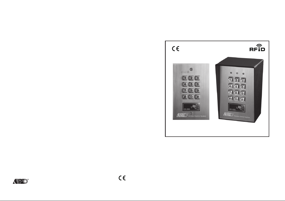
VANDAL RESISTANT
BACK-LIT WEATHERPROOF
RFID ACCESS CONTROL KEYPAD
DK-2882
User Manual (MK-II)
AEI PROTECT-ON SYSTEMS LIMITED
www.apo-hk.com
FOR ELECTRIC LOCK, INTER-LOCK
AND SECURITY SYSTEM INSTALLATIONS

TABLE OF CONTENTS
INTRODUCTION
FEATURES
OPTIONAL DEVICES FOR SYSTEM EXPANSION
SPECIFICATIONS
INSTALLATION
Precautions
CONNECTION TERMINALS
OTHER FACILITIES
On-Board LED Indicators
Pacifier Tone & The LED Signals
Jumper for Back-Lit Selection
PREPARATION FOR PROGRAMMING
A) Criteria for Codes and Cards
B) Security Level of The Operation Media
C) List of User Information
PROGRAMMING AND OPERATION
Power Up The Keypad
Set Keypad into Programming Mode with Master Code
Direct Access to Programming Mode with The “DAP” Code – 2 8 2 8
System Refreshing with “Refreshing Code” --- 9 9 9 9
The Default Values of The Keypad
Master Code
Super User Code
Operation and Functions of The Super User Code
Common User Codes for Output 1, 2 & 3
User Codes/Card For Output 1, 2 & 3
Examples – Programming And Operation
Visitor Codes (For Output 1 Only)
Duress Codes (For Outputs 1, 2 & 3)
Operation And Function of The Duress Code
Output Modes & Timing for Output 1, 2 and 3
System Real-Time-Clock
Start & Stop Times For Daily Inhibition of Output 1
Personal Safety And System Lock-Out
User Code Entry Mode - Auto or Manual
Pacifier Tones On-Off Selection
Output Operation Announcer
Status LED Flashing On-Off during Standby
Door Forced Open Warning & Timing
Door Propped-Up Warning & The Delay Time
Intelligent Egress Button – An Unique Feature of A Contemporary Keypad
Where And Why “Going Out” Needs Attention
Egress Delay , Warning And Alarm
······································································································································· 4
················································································································································ 4
·················································································· 5
···································································································································· 6
········································································································································· 7
············································································································································ 7
··············································································································· 8-11
································································································································ 11
······················································································································· 11
··········································································································· 11
················································································································· 11
····························································································· 12-13
·············································································································· 12
························································································· 12-13
····················································································································· 13
·································································································· 14-37
···························································································································· 14
·········································································· 14
························································· 15
··········································································· 15
········································································································· 16
·········································································································································· 17
···································································································································· 17
········································································ 18-19
······························································································· 20
···································································································· 21
·························································································· 22-24
···································································································· 25-26
······························································································· 27-29
················································································ 28-29
······················································································· 30
························································································································· 31
··········································································· 32-33
··································································································· 34
································································································ 35
·············································································································· 35
················································································································· 36
··························································································· 36
···································································································· 37
························································································ 37
········································38-39
·············································································38-39
··································································································· 40-41
AUXILIARY INFORMATION
DRY CONTACT
A dry contact means that no electricity is connected to it. It is prepared for free connections. The
Relay Output contacts provided in this keypad system are dry contacts.
N.C.
Normally Closed, the contact is closed circuit at normal status. It is open circuit when active.
N.O.
Normally Open, the contact is open circuit at normal status. It is closed circuit when active.
TRANSISTOR OPEN COLLECTOR OUTPUT
An open collector output is equivalent to a Normally Open (N.O.) contact referring to ground
similar to a relay contact referring to ground. The transistor is normally OFF, and its output
switches to ground (-) when active. The open collector can only provide switching function for
small power but it is usually good enough for controlling of an alarm system. The Duress,
Inter-lock and Key Active/Alarm Outputs of the keypad are open collector outputs.
OPEN COLLECTOR
OUTPUT ----
Output switches to
ground when activated
EQUIVALENT
N.O. CONTACT
OUTPUT ----
Output switches to
ground when activated
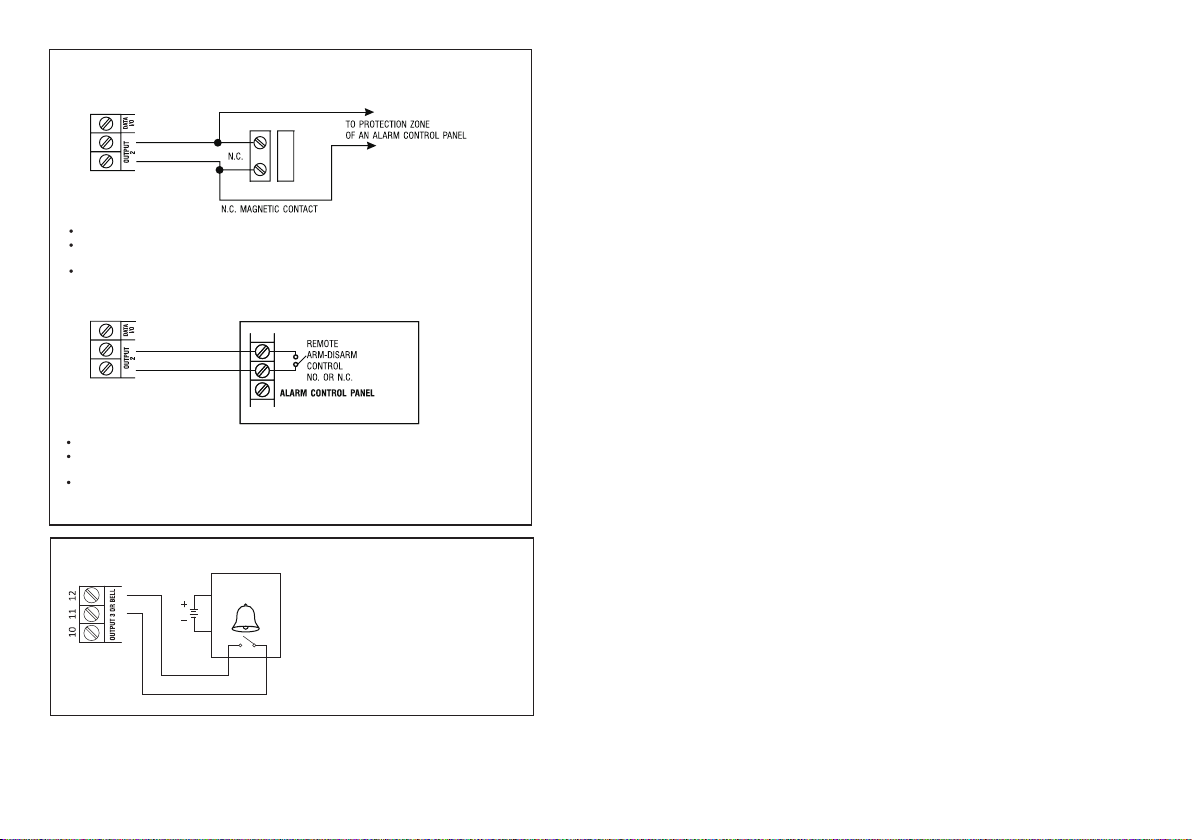
(F) OUTPUT 2
( i ) Shunting an N.C. Zone
Put Output 2 jumper to N.O.
Use the Normally Open (N.O.) output contact to shunt a Normally Closed (N.C.) protection zone of an
alarm system.
Set output contact to Start / Stop Mode (Programming Option 52, Output Mode=0).
( ii ) Alarm System Arm-Disarm Control
Use the (N.O.) or (N.C.) output contact to make arm-disarm control of an alarm system.
Consult your alarm control panel manual for the appropriate output contact for arm-disarm control.
Usually set output 2 to Momentary mode (Programming Option 521, Location 52, Output Mode=1) for
multi station systems and Start / Stop mode (Programming Option 520, Location 52, Output Mode=0)
for single station systems.
Door Opening Alarm & Timer
Programming Locations For System Expansion
Wiegand Data Output Mode
Wiegand Data Output Format
Operation Modes
Close The Programming Mode
PROGRAMMING MAKE SIMPLE - For General Users
FACILITIES FOR WIEGAND OUTPUT
WIEGAND OUTPUT FORMATS
PROGRAMMING SUMMARY CHART
APPLICATION EXAMPLES
A Stand Alone Door Lock
An Inter-Lock System Using Two Keypads
APPLICATION EXPANSIONS
The Axiliary Readers & Keypad
The Split-decoders
1) Dual-station Access Control Door Lock
2) Multi-station Access Control Door Lock
3) Split-decoded Access Control Door Lock
4) Split-decoded Multi-station Access Control Door Lock
APPLICATION HINTS FOR THE AUXILIARY TERMINALS
AUXILIARY INFORMATION
·················································································································· 42
························································································ 43
··················································································································· 43
················································································································· 44
···································································································································· 45
················································································································ 45
····································································· 46-47
····································································································· 48
·········································································································· 49-52
································································································ 53-55
················································································································ 56-57
························································································································ 56
····························································································· 57
············································································································ 58-61
··············································································································· 58
·································································································································· 59
························································································· 60
·························································································· 61
························································································· 62
····················································································································· 67
····································································· 63
································································ 64-66
(G) OUTPUT 3 -- Door Bell Button (DK-2882B or D ONLY)
(OPTIONAL)
ELECTRONIC
DOOR CHIME
N.O.
DOOR
BELL
The output 3 of the DK-2882B or D is
prepared for triggering a low power door
chime. DO NOT use it as a high voltage
power path for a door bell. The maximum
power rating of the contact is 24V DC/1 Amp.
Connect the N.O. output contact in parallel
with the door bell button.
INTRODUCTION
DK-2882 is a self-contained three output relay, vandal resistant and weatherproof keypad. It
combines the digital keypad and proximity EM card reader in one unit.
The keypad has been designed for full feature stand alone access control applications. It is
expandable to work with an optional decoder (DA-2800 or DA-2801) for high security split-decoded
operation. It is also compatible with the auxiliary card reader (AR-2802) and the auxiliary keypad
readers (AR-2806, AR-2807 and AR-2809) for upgrading a stand alone or split-decoded system to
multi-station operation.
The keypad is ideally for door strike and alarm arm-disarm controls. It is also a programmable
industrial timer (from 1 second to over 24 hours) for automatic operator system.
In the line of DK-2882 keypads are available for surface mount and flush mount versions.
Surface Mount / Gooseneck Mount Keypads:
DK-2882A – Output Relay 1, 2 & 3 Controlled by User Codes / Cards
DK-2882B – Output Relay 1 & 2 Controlled by User Codes / Cards; Output 3 by Bell Button
Flush Mount Keypads:
DK-2882C – Output Relay 1, 2 & 3 Controlled by User Codes / Cards
DK-2882D – Output Relay 1 & 2 Controlled by User Codes / Cards; Output 3 by Bell Button
FEATURES
A member of the Tri-Tech series keypads compatible with the optional controllers & reader keypads
for system expansion
Loaded with the 2nd generation DK-2800 operation software
Built-in with all the logics for stand alone, split-decoded and multi-station operations
Controls “Going in” with User Codes / Cards and “Going out” with feature programmable egress
button
Independent control for the three output relays with programming timer
Total 1,200 User Codes / Cards for controlling of the three outputs
Indoor or outdoor installation with IP-66 all weather ingress protection
Stainless steel faceplate combines with die-casting metal back-lit key buttons
Vandal resistant durable steel housing for surface or gooseneck mounting
Package Contents
• One DK-2882 Keypad
• Two EM Cards
• One Pack of Mounting Screws
• One Centre Pin Torx Screw Wrench
• One Programming & Installation Manual
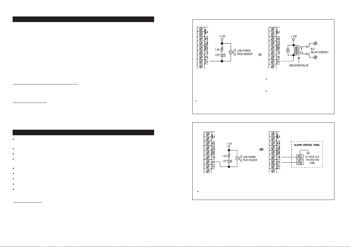
(D) KEY ACTIVE -- SET THE "K OR A" JUMPER TO "K"
(a) (b)
The Key Active Output switches to (-) ground
for 10 seconds whenever a key is touc hed.
You may use it to turn ON an LED lamp and
/or a small buzzer t o notify a guard; or
to energize a relay to switch ON lights or
trigger an CCTV Camera to start recording.
Make sure that the relay for switching ON
lights has high enough isolation between
high voltage and low voltage to prevent
damage of the keypad.
Only one connection option is recommended.
Make s ure the sink current does not exceed
the maximum rating of 100mA.
External power supply and isolat ion relay
are strict ly necessa ry i n driving high power
device, such as lights.
(E) DURESS OUTPUT
The Duress Output switches to (
ON an LED lamp and/ or a small buzzer to notify a guard; or connect it to a 24 hour Normally
Open protection zone of an alarm system.
Only one connection option is recommended. Make sure t hat the sink current does no
exceed the maximum rating of 100mA.
-
) ground when duress code is entered. You may use it to turn
t
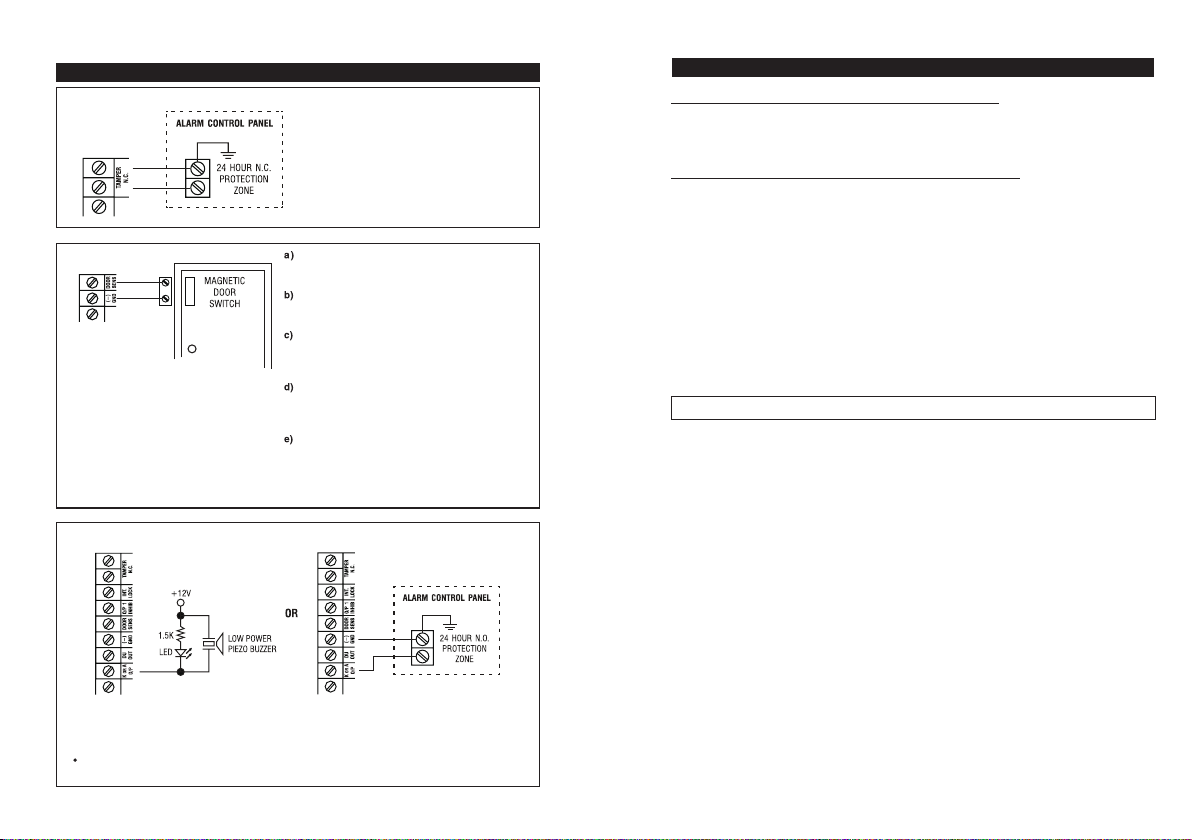
APPLICATION HINTS FOR THE AUXILIARY TERMINALS
(A) TAMPER N.C.
The tamper switch is Normally Closed while the
keypad is secured on gang box. It is open when
the keypad is removed from the gang box. To
prevent sabotage, connect these terminals in
series with a 24 hour N.C. protection zone of an
alarm system if required.
(B) DOOR SENS
With the help of a Normally Closed
door position sensor (usually a
magnetic door switch) on the door to
set up the following functions:
Door Auto Relock -- The system will
immediately relock the door after a valid access
has been gained to prevent "tailgate" entries.
Door Forced-ope n Alarm -- The keypad will
generate alarm instantly if the door is forced to
open. Enable the function at Location 80.
Door Propped-up Al arm -- The keypad will
generate alarm if the door is left open longer
than the pre-set delay time. Enable the function
at Location 81.
Inter-lock Control -- When the door is open,the
interlock output of the keypad will give a (-)
command to stop the other keypad in an
inter-lock system.
Door Opening Alarm -- Door Opening Alarm is
designed f or the emergency door only. It is
always given when the door is opened unless a
valid user code or card is used prior to the door is
opened. Enable the function at Location 91.
(C) ALARM OUTPUT -- SET THE "K OR A" JUMPER TO "A"
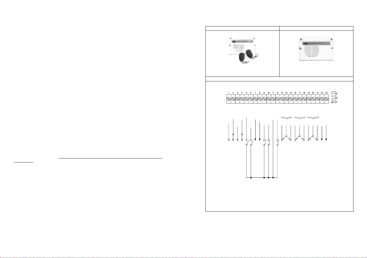
OPTIONAL DEVICES FOR SYSTEM EXPANSION
The Optional Decoders Available for Split-decoded Operation
DA-2800 – Full Feature Decoder with RF Remote Control
DA-2801 – Full Feature Decoder
The Auxiliary Reader / Keypad Available for Multi-station Operation
AR-2802S or A – EM Card Reader
AR-2806S or A – EM Card Reader with Digital Keypad
AR-2807S or A -- EM Card Reader with Digital Keypad
AR-2809S
Remark:
The suffix letter “S” stands for standard version and “A” stands for advanced version. The advanced
version possesses the standand features and also provides Wiegand and RS-232 data outputs for the
custom projects with external controller and PC.
-- EM Card Reader with Digital Keypad
Please contact your local agent for the optional devices.
The Alarm Output switches to (
Delay. You may use it to turn ON an LED lamp and/ or a small buzzer to notify a guar d; or
connect it to a 24 hour Normally Open protection zone of an alarm system. See Location 80 and
Location 91 for more information about these functions.
Only one connection option is recommended. Make sure that the sink current does not
exceed the maximum rating of 100mA.
-
) ground in door forced to open or the door open after Egress
SPECIFICATIONS
A
Operating Voltage:
12V-24V DC, Auto adjusting
Operating Current:
75mA (quiescent) to 145mA
Operation Temperature:
-20 C to +70 C
Environmental Humidity:
5-95% relative humidity non-condensing
Working Environment & Ingress Protection:
All weather, IP-66
Number of Users:
Output 1 – 1,000 (Codes and/or Cards) + 50 Duress Codes
Output 2 – 100 (Codes and/or Cards) + 10 Duress Codes
Output 3 – 100 (Codes and/or Cards) + 10 Duress Codes
Proximity Card:
Standard EM Card or Keyfob, 125Khz
Number of Visitor Codes:
50, programmable for one time or with time limit
Timings for Code Entry and Card Reading:
10 seconds waiting for next digit entry
30 seconds waiting for code entry after card reading
The Timers:
Three 1-99,999 Seconds (Over 24 Hours possible) Independent Programmable Timers for O/P 1, 2
& 3
Egress Button:
Programmable for Instant, Delay with Warning and/or Alarm
Momentary or Holding Contact for Exit Delay
Input Sensing Terminals:
a) Door position, b) Egress, c) O/P 1 inhibit
Output Control Terminals:
Transistor Open Collector 24VDC/100mA sink Max for the following outputs
a) Duress, b) Alarm, c) Key Active, d) Output 3 (Door Bell version only), e) Inter-lock
Output Contact Ratings:
Output Relay 1 – N.C. & N.O. dry contacts, 5A/24VDC Max.
Output Relay 2 – N.C. & N.O. dry contacts, 1A/24VDC Max.
Output R elay 3 – N.C. & N.O. dry contacts, 1A/24VDC Max. (N.O. contact only for Door Bel l
version)
Tamper Switch – N.C. dry contact, 50mA/24VDC Max.
Dimensions:
DK-2882A / DK-2882B – 156(H) X 103(W) X 50/70(D)mm
DK-2882C / DK-2882D – 151(H) X 97.5(W) X 42(D)mm
Weight:
DK-2882A / DK-2882B – 1.03Kg net
DK-2882C / DK-2882D – 460g net
Housing:
DK-2882A / DK-2882B – Anodized steel, powder paint coating outer box & plastic inner box
DK-2882C / DK-2882D – Plastic back box
Faceplate Material:
1.5mm stainless steel
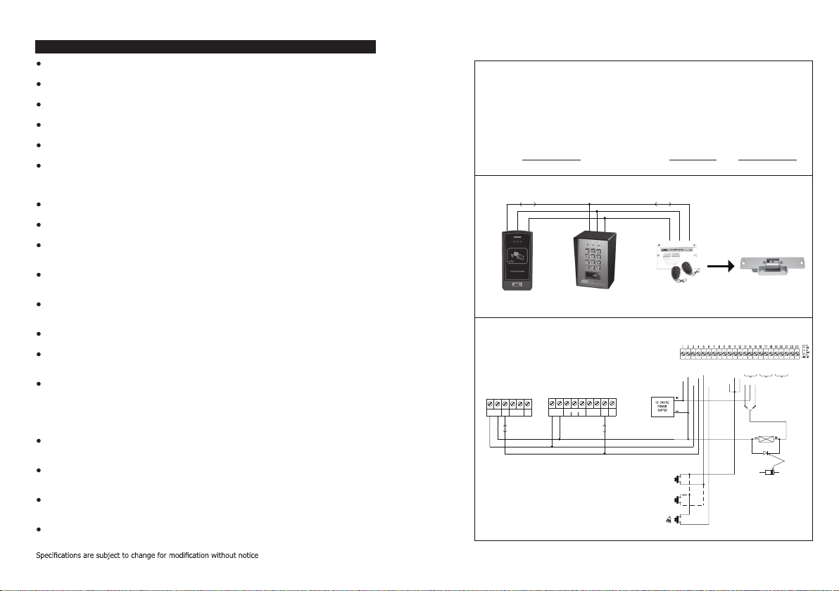
4) Split-decoded Multi-station Access Control Door Lock
Description
This is an expansion of application (3). The DK-2882 is expandable to a multi-station system in
Split-decoded operation. It is compatible with the auxiliary readers AR-2802 and the auxiliary
reader-keypads AR-2806, AR-2807 & AR-2809. Total 3 auxiliary readers or reader-keypads can
be connected in parallel with the Data I/O Bus. They provide the same functions like the master
keypad in using cards and user codes. The DK-2882 that is the server of the system manages
the data with its Data I/O Bus among the associated devices. This approach gives high security
in sabotage prevention and user convenience.
Note: Make Operation Mode setting of the keypad in “Server Mode” with Location 94 = 1 in
this application.
System Connection
DATA I/O BUS
(+) POWER SUPPLY
(–) COMMON GND
DA-2800 OR DA-2801
(DECODER)
-
-
DOOR SENS- O/P 1 INHIB- IN
DU OUT- DOOR BELL IN- EG IN- D
T.
L
(
-
OCK
)
OUTPUT 1 OUTPUT 2 OUTPUT 3
N.C.
ELECTRIC LOCK
N.O.
OUTPUT RELAY 1
N.O. Output for Fail-secure Lock
N.C. Output for Fail-safe Lock
ELECTRIC LOCK
1N4004
CATHODE
-
ALARM O/P- KEY ACT O/P- N.O.- COM- N.C.- N.O.- COM- N.C.- N.O.- COM- N.C.- TAMPER- GND
AR-2802/06/07/09
AUXILIARY READER
OR KEYPAD-READER
Wiring Diagram
AR-2802/06/07/09
AUXILIARY READER
OR KEYPAD-READER
( + ) ( – )
12-24V DC
654321
DATA
TAMPER
LED
I/O
N.C.
( + ) ( – )
12-24V DC
DK-2882
(SERVER)
OUTPUT 1
DK-2882
(SERVER)
N.OCONN.C
DA-2800 OR
DA-2801
(DECODER)
-
-
KEYPAD PWR- GND
12-24V DC
ATA I/O
(
)
987
654321
EGINDATA
OUTPUT
I/O
2
(–) COMMON GND
(+) POWER SUPPLY
DATA I/O BUS
D-1312 OR AP-960
DIGITAL KEYPAD
EGRESS BUTTON
MORE EGRESS
BUTTON CAN
BE CONNECTED
IN PARALLEL
DOOR BELL
BUTTON
(
-
)
N.O.
(
-
)
N.O.
(
-
)
N.O.
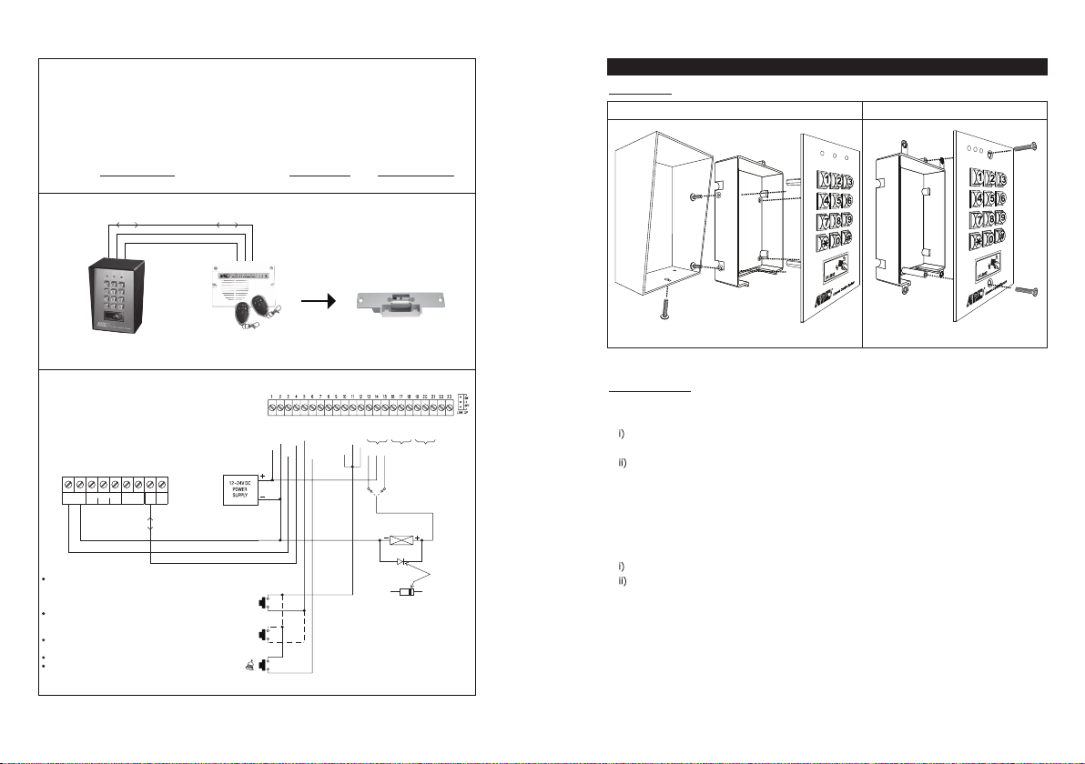
3) Split-decoded Access Control Door Lock
Description
Apart from stand-alone operation, the DK-2882 can be up-graded to high security Split-decoded
operation with a decoder unit DA-2800 or DA-2801. The decoder is inside the house with all the
input and output installations connecting to it. The DK-2882 manages the data in the system
with its Data I/O Bus. The decoder operates the door lock and the appliances directly according
to the commands from the keypad unit. This approach prevents the electric door lock or
appliance be operated due to sabotage at the external keypad.
Note: Make Operation Mode setting of the keypad in “Server Mode” with Location 94 = 1 in
this application.
System Connection
DATA I/O BUS
(+) POWER SUPPLY
(–) COMMON GND
INSTALLATION
ASSEMBLY
Surface Mount Version Flush Mount Version
DK-2882
(SERVER)
Wiring Diagram
DK-2882
(SERVER)
OUTPUT 1
( + ) ( – )
12-24V DC
NOTE:
Connect the 1N4004 as close as possible to the lock in
parallel with the lock power terminals of the lock to absorb
the back EMF to prevent it from damaging the keypad. The
1N4004 is not required if the electric lock is AC operated.
To avoid Electro-Static-Discharge from interfering with the
operation of the keypad, always ground the (-) terminal of
the keypad to earth.
Always connect DOOR SENSOR terminal to (-) ground if not
used.
Always connect TAMPER terminal to (-) ground if not used.
Make 3-wire Connection (+, -, DATA I/O) to the keypad in
the DK-2800 series. More than one keypads can be
connected in parallel.
987654321
EGINDATA
OUTPUT
N.OCONN.C
I/O
2
(–) COMMON GND
(+) POWER SUPPLY
DATA I/O BUS
DA-2800 OR
DA-2801
(DECODER)
DA-2800 OR DA-2801
(DECODE)
AD-1312 OR AP-960
DIGITAL KEYPAD
EGRESS BUTTON
MORE EGRESS
BUTTON CAN
BE CONNECTED
IN PARALLEL
DOOR BELL
BUTTON
-
-
GND
12-24V DC
(
)
N.O.
N.O.
N.O.
ELECTRIC LOCK
Plastic back boxPlastic inner boxSteel Box FaceplateFaceplate
PRECAUTIONS
-
-
-
-
DOOR SENS- O/P 1 INHIB- IN
DU OUT- DOOR BELL IN
EG IN- D
KEY
ATA I/O
T.
L
P
AD PW
R
(
-
)
(
-
)
-
)
(
(
-
OC
)
K
-
N.O.- COM- N.C.- N.O.- COM- N.C.- TAMPER- GND
OUTPUT 1 OUTPUT 2 OUTPUT 3
N.O.
N.C.
OUTPUT RELAY 1
N.O. Output for Fail-secure Lock
N.C. Output for Fail-safe Lock
ELECTRIC LOCK
1N4004
-
ALARM O/P- KEY ACT O/P- N.O.- COM- N.C
.
CATHODE
1) Prevent Interference:
The EM Card reader is working at the frequency of 125Khz. Installation precautions are necessary.
Make sure the location for installation has no strong low frequency electro-magnetic wave. Especially
in the range of 100-200Khz
If there is more than one keypads with the same operation frequency installed closely in the
location, make sure that they are at least 60cm (2ft) apart from each other to prevention
interference.
2) Prevent Accidental Short Circuit:
In the previous experience, most of the damages caused in the installation are accidental touching
of the components on circuit board with the wires carrying power. Please be patient to study the
manual to become familiar with the specifications of the system before starting the installations.
Do not apply power to the system while it is in installation.
Check carefully all the wirings are correct before applying power to the system for testing.
WIEGAND
HARNESS
BACK-LIT JUMPER
K OR A JUMPER
OUTPUT 2
JUMPER
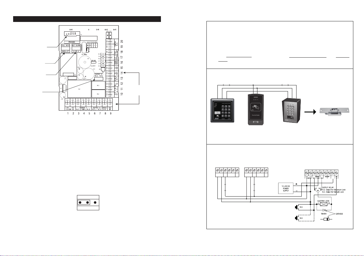
CONNECTION TERMINALS
CONNECTION
TERMINALS
2) Multi-station Access Control Door Lock
Description
This is an expansion of application (1). The DK-2882 is expandable to a multi-station system for
user convenience with the auxiliary readers AR-2802 and/or the auxiliary reader-keypads
AR-2806, AR-2807 &r AR-2809. Total 3 auxiliary readers or reader-keypads can be connected in
parallel with the Data I/O Bus and they provide the same functions like the master keypad in
using cards and user codes.
Note: Keep Operation Mode setting of the keypad in “Keypad Mode (default)” with Location
94= 0 in this application.
System Connection
DATA I/O BUS
(+) POWER SUPPLY
(–) COMMON GND
1 - 2 : 12-24V DC (Power Input Terminal)
Connect to 12-24V DC power supply. The (-) supply and the (-) GND are the common grounding
points of the system. The system accepts full input voltage range with no adjustment.
3 - 4 - 5 : OUTPUT 1 (Output Relay 1)
5 Amp relay dry contact controlled by the Group 1 User Codes/Cards, recommended for door strike.
Terminal 3 is Normally Closed (N.C.), terminal 5 is Normally Open (N.O.) and terminal 4 is the
common point of the two contacts. Use N.C. output for Fail-safe locking device; and N.O. output for
Fail-secure locking device. The relay is programmable for Start/Stop (toggle) mode or Momentary
timing mode. See programming Location 51 for the details.
6 – 7 : OUTPUT 2 (Output Relay 2)
1 Amp relay dry contact controlled by the Group 2 User Codes/Cards. It is an auxiliary output
contact for controlling security system or automatic operator. It is selectable for N.C. (Normally
Closed) or N.O. (Normally Open) with jumper and the operation mode is programmable for
Start/Stop (toggle) or Momentary with timing. See programming Location 52 for the details.
OUTPUT 2
N.O. N.C.
OUTPUT 2 JUMPER
8 : DATA I/O PORT (Data Communication Bus)
The Data I/O port is prepared for setting up a data bus for the connection of the auxiliary
reader-keypads and the split-decoder in system expansion. See the examples in “Application
Expansions” section for the details.
AR-2806 OR
AR-2807 OR
AR-2809
(AUXILIARY KEYPAD-READER)
Wiring Diagram
AR-2806 OR
AR-2807 OR
AR-2809
DATA
TAMPER
( + ) ( – )
I/O
12-24V DC
AUXILIARY
KEYPAD-READER
ELECTRIC LOCK
AR-2802S OR
AR-2802A
(AUXILIARY READER)
AR-2802S OR
AR-2802A
654321
DATA
TAMPER
( + ) ( – )
LED
12-24V DC
N.C.
AUXILIARY
READER
I/O
LED
N.C.
DATA I/O BUS
(+) POWER SUPPLY
(–) COMMON GND
DK-2882
(MASTER KEYPAD)
DK-2882
DK-2882 (MASTER KEYPAD)
987654321
DATA
I/O
654321
AD-1312 OR AP-960
EGRESS BUTTON
(INSIDE THE HOUSE)
MORE EGRESS
BUTTONS CAN
BE CONNECTED
IN PARALLEL
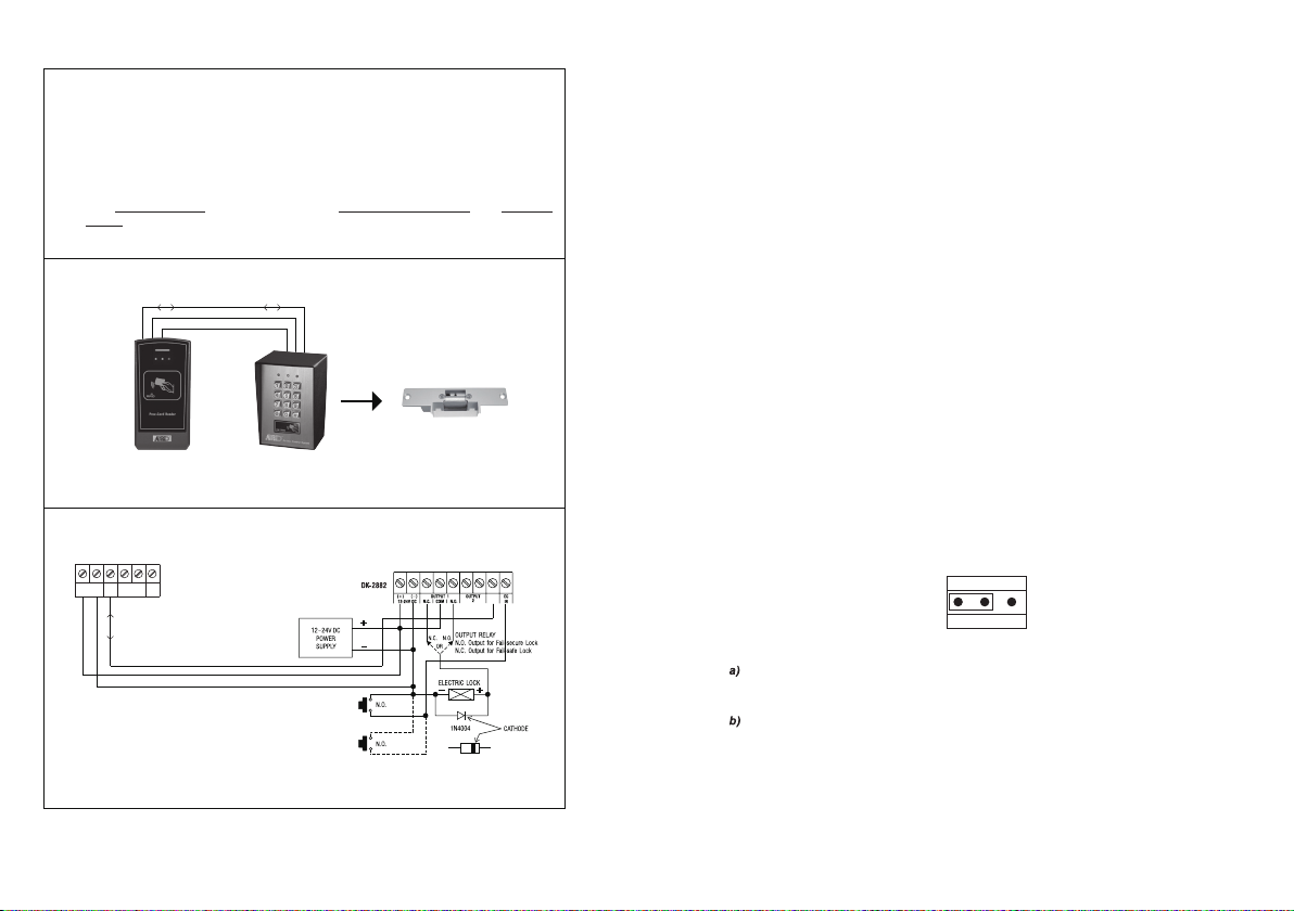
1) Dual-station Access Control Door Lock
Description
Owner can select an auxiliary reader AR-2802 or an auxiliary reader-keypad AR-2806, AR-2807
or AR-2809 and connect it with the master keypad DK-2882 to expand the system with
dual-station for user convenience. Simply connect the reader or the reader-keypad in parallel
with the Data I/O Bus of the master keypad. The auxiliary reader accepts all the cards that are
programmed in the master keypad. If it is an auxiliary reader-keypad it accepts cards and user
codes like the master keypad.
Note: Keep Operation Mode setting of the keypad in “Keypad Mode (default)” with Location
94 = 0 in this application.
System Connection
DATA I/O BUS
(+) POWER SUPPLY
(–) COMMON GND
ELECTRIC LOCK
AR-2802 S or A
(AUXILIARY READER)
DK-2882
(MASTER KEYPAD)
Wiring Diagram
DK-2882 MASTER KEYPAD
DATA
I/O
( + ) ( – )
12-24V DC
DATA
TAMPER
I/O
N.C.
654321
AR-2802S AUXILARY READER
OR
LED
AR-2802A
DATA I/O BUS
(+) POWER SUPPLY
(–) COMMON GND
AD-1312 OR AP-960
EGRESS BUTTON
(INSIDE THE HOUSE)
MORE EGRESS
BUTTONS CAN
BE CONNECTED
IN PARALLEL
Dual-Station Access Control Door Lock
9 : EG IN ( Egress Input)
A Normally Open (N.O.) input terminal referring to (-) ground. With the help of connecting a
normally open button to activate Output 1 for door opening like using Codes/Cards.
Egress button is usually put inside the house near the door. More than one egress buttons can be
connected in parallel to this terminal. Leave this terminal open if not used.
See Programming Locations 90 and 91 for more information about the Egress Button with
programmable features.
10 - 11 - 12 : OUTPUT 3 (Output Relay 3) --- For DK-2882A & DK-2882C Only*
1 Amp relay dry contact controlled by the Group 3 User
“A” & “C” keypads, it is an auxiliary output contact for controlling security system or automatic
operator. Terminal 10 is Normally Closed (N.C.), terminal 12 is Normally Open (N.O.) and terminal 11
is the common point of the two contacts. It is programmable for Start/Stop (toggle) mode or
Momentary with timing. See programming Location 53 for the details.
10 : OUTPUT 3 (Open Collector Output) --- For DK-2882B & DK-2882D Only*
An NPN transistor open collector output is for version “B” & “D” keypads, which is controlled by the
Group 3 User Codes/Cards. It has the maximum power rating of 24VDC/100mA sink. It is equivalent
to an N.O. (Normally Open) terminal referring to ground. It can be used to drive small power device,
such as a relay or a low power control point of other equipment. This output point is programmable
for Start/Stop (toggle) or Momentary with timing. See programming Location 53 for the details.
11 - 12 : DOOR BELL (Relay Contact for Door Bell) --- For DK-2882B & DK-2882D Only*
Door Bell output is for version “B” & “D” only. It is a Normally Open (N.O.) relay dry contact with
maximum rating of 24VDC/1Amp. It is a triggering contact of a low voltage door chime. The contact
point keeps close as long as the bell button on the keypad is pressed. See “Application Hints for the
Auxiliary Terminals” Section(G) for the details.
13 : “K” OR “A” O/P (Keypad Active Output or Alarm Output)
An NPN transistor open collector output with maximum power rating of 24VDC/100mA sink. It is
equivalent to an N.O. (Normally Open) terminal referring to ground. It can be used to drive small
power device, such as a relay or a low power control point for other equipment. This output point is
selectable to give Keypad Active Output or Alarm Output via the “K or A” jumper.
Codes or Cards for Output 3 in the version
KEY ALARM
K OR A
KEY-ALARM JUMPER
Keypad Active Output (“K”) --- It switches to (-) ground for 10 seconds on each key touch. It
can be used to turn on light, CCTV camera, or buzzer to notify a guard. See Application Hints for
more information.
Alarm Output (“A”) --- It switches to (-) ground while Alarm occurs in order to trigger external
alarm to give notification at remote location.
14 : DU OUT (Duress Output)
An NPN transistor open collector output with maximum power rating of 24VDC/100mA sink. It is
equivalent to an N.O. (Normally Open) terminal switching to (-) ground after the Duress Code is
entered. Use it to trigger an alarm zone of a security system, or turn on a buzzer to notify a guard.
15 : (-) GND (Common Ground)
D
A grounding point of the keypad that is common to terminal 2.
16 : DOOR SENS N.C. (Door Position Sensing Input -- Normally Close)
A Normally Closed (N.C.) sensing point referring to (-) ground, with the help of a normally closed
magnetic contact monitors the open or close status of the door. It initiates the following functions for
the system. Connect it with jumper to (-) Ground if not used.
a) Door Auto Re-lock
The system immediately re-locks the door after it is re-closed before the end of the programmed
time for output 1. It prevents unwanted “tailgate” entry.
b) Door Forced Open Warning
The keypad generates “door forced open” warning and alarm instantly once the door is forced to
open without a valid user Code, Card or egress button. The warning lasts as long as the time
programmed (1-999 sec). It can be stopped with an User Code or card for output 1 at anytime.
See programming Location 80 for the details.
c) Door Propped-up Warning
The keypad generates propped-up warning beeps (does not activates alarm output) while the
door is left open longer than the allowable time programmed. The warning will last as long as the
door is open until re-closed. See programming Location 81 for the details.
d) Inter-lock Control
The inter-lock control output always goes to (-) while the door is open, which gives signal to
disable the partner keypad in an inter-lock system. See the Inter-lock terminal 18 description for
more information.
e) Door Opening Alarm
Door Opening Alarm is designed for the emergency door only. It is always given when the door
is opened unless a valid user code or card is used prior to the door is opened. See programming
Location 91 for the details.
17 : O/P 1 INHIBIT N.O. (Output 1 Inhibit Control Input – Normally Open)
A Normally Open (N.O.) sensing input point for controlling the Output 1, with this terminal
connecting to (-) ground, the Egress Button, the group of User PINs and Cards for Output 1 are
all disabled. It is prepared mainly for the cross wire connection with the “Inter-lock O/P” point of
the partner keypad in an Inter-lock system.
NOTE: The inhibit function does not govern the Duress Codes and the Super User Codes. They are
always valid.
18 : INTER-LOCK O/P (Inter-lock Control Output)
An NPN transistor open collector output with maximum power rating of 24VDC/100mA sink. It is OFF
at normal condition and it switches to (-) ground immediately for the first 5 seconds after keying in
a valid User Code or reading a card to operate Output 1, then, it will keep tying to (-) ground during
the Door Position Sensor is open circuit due to door opening. Use this output point to make cross
wire connection with the partner keypad’s “O/P 1 Inhibit” point in an Inter-lock system to prevent
both doors can be opened at the same time.
An Inter-lock System:
An inter-lock system is a two-door system that always allows only one of the doors to open during
the operation. While one of the doors is opened, the other door keeps close until the open door is
re-closed. It prevents the unauthorized people dashing into a protected area while the doors are in
use.
An inter-lock system needs two keypads and two door position sensing switches for the two doors.
The Split-decoders (Optional)
Connection Terminal
-
-
-
-
-
-
DOOR BELL IN
DATA I/O
GND(
12-24V DC
EG IN
KEYPAD PWR
)
INPUT/OUTPUT FOR SPLIT-DECODED SIGNALS
POWER OUTPUT FOR KEYPADS
COMMON GROUND
POWER INPUT FOR SYSTEM
N.
N.O. S
O. SW
W
-
-
-
-
-
-
DU OUT
OPEN COLLECTOR OUTPUT
T
GND(
O/P 1 INHI
INT. LOCK
DOOR SENS
AMPER
)
B
OPEN COLLECTOR OUTPUT
N.C. SW
COMMON GROUN
N.C. SW
N.O. S
W
DA-2801DA-2800
Standard DecoderDecoder with RF Remote Control
-
-
-
-
N.O.
N.C.- N.O.
N.C.
COM
1A RELAY
FOR AU
XILIARY CONTROL
DRY CONTACTS
-
COM
1A RELAY DRY CONTACTS
FOR AUXILIARY CONTROL
-
-
COM
N.C.
OUTPUT 1 OUTPUT 2 OUTPUT 3
5A RELAY
FOR DOOR STRIKE
DRY CONTACTS
-
-
-
AL
N.O
KEY ACT O/P
ARM O/P
.
OPEN COLLECTOR OUTPUT
OPEN COLLECTOR OUTPUT
APPLICATION EXPANSIONS
Apart from standard-alone operation, DK-2882 is expandable to be a Multi-station System or a High
Security Multi-station Split-decoded System with its Data I/O Bus for the connection of the optional
auxiliary keypad(s) and decoder. The wiring is very simple. Just connect all the related devices in
parallel with the Data I/O Bus. The DK-2882 is the server that manages the data among them.
A Multi-station System provides higher security in access control and user convenience to operate an
electric lock at different locations. Such as a dual keypad system for area needs controlling of going
in and going out with user codes or EM cards.
A Split-decoded keypad system increases the overall security with keypad(s) installing outside and
decoder installing inside. It prevents the door can be opened due to sabotage at the external
keypad(s). A Split-decoded system is also compatible with the auxiliary keypads for multi-station
operation. It is a perfect system for overall higher security and user convenience.
The application examples here show the connections of the auxiliary keypads and the decoder to the
server keypad. Please contact your local agent for these optional devices if increasing security and
user convenience to the system is required.
The auxiliary reader / keypads and the decoders are compatible with all the 2nd generation keypads
in the DK-2800 series.
The version"A" auxiliary reader keypads are available, which provide Wiegand and RS-232 data
outputs.
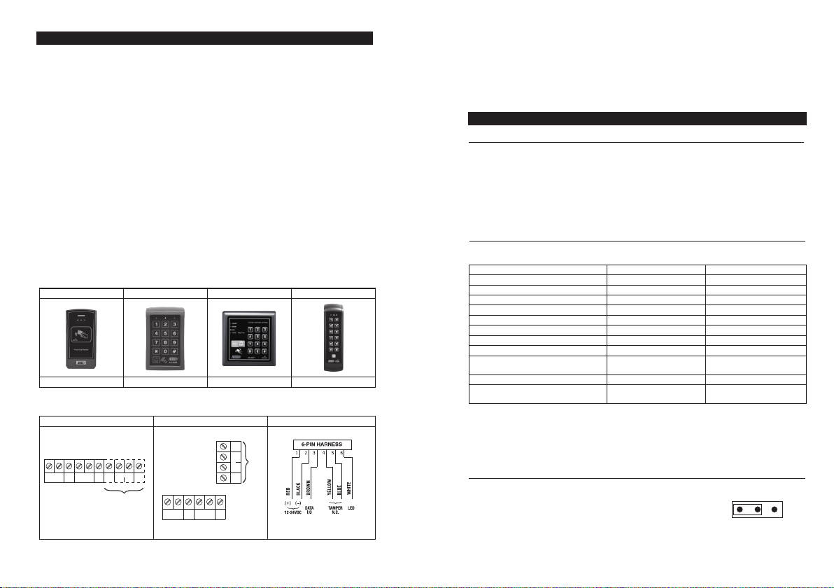
The Axiliary Readers & Keypad (Optional)
AR-2809AR-2807AR-2806AR-2802
Aux. Reader-KeypadAux. Reader-KeypadAux. Reader-KeypadAux. Reader
Connection Terminal
DATA
TAMPER
( + ) ( – )
12-24V DC
LED
BUZ
I/O
N.C.
Version"A" ONLY
WIEGAND
D0 D1
RS
10987
TAMPER
232
WIEGAND
D0 D1
Version"A" ONLY
BUZ
654321
LED
N.C.
10987654321
RS
232
DATA
( + ) ( – )
I/O
12-24V DC
AR-2809AR-2806AR-2802 and AR-2807
19 - 20 : TAMPER N.C. (Tamper Switch Normally Closed Contact)
A normally closed dry contact while the keypad is secured on its box. It is open while keypad is
separated from the box. Connect this N.C. terminal to the 24 hour protection zone of an alarm
system if necessary.
NOTE: The tamper switch in the DK-2882A and DK-2882B is activated by the fixing screw of the
front plate; in the DK-2882C and DK-2882D it is activated by a magnet equipped on the back of the
plastic box.
OTHER FACILITIES
ON-BOARD LED INDICATORS
RED / GREEN (Right) ---
AMBER (Centre) ---------
RED / GREEN (Left) -------
It lights up in Green for Output 1 activation; and Red for Output 2
activation.
It flashes in Standby. It shows the system status in synchronization
with the beep tones. The standby flashing can be OFF with
programming. See Location 73 for the details.
It lights up in Red while one of the outputs is inhibited. It is flashing
during inhibition paused.
It is the Wiegand LED for feedback indication. It lights up in Green.
PACIFIER TONES & THE LED SIGNALS
The buzzer and the amber LED indicator give following tones and signals respectively for system
status:
1) In Programming Mode ----- ON
2) Successful Key Entry 1 Beep 1 Flash
3) Successful Code / Card Entry 2 Beeps 2 Flashes
4) Unsuccessful Code / Card Entry 5 Beeps 5 Flashes
5) Power Up Delay Continuous Beeps Continuous Flashes
6) Output Relay Activation ** 1 Second Long Beep
7) In Standby *** ----- 1 Flash in 1 Second Interval
8) System Refreshing ----- Fast Flashes for 2.5 Minutes
System
power failure
NOTE:
*
* *
* * *
STATUS TONES * AMBER LED
-----
1 Long Beep
Card or Code Already Stored in
All Pacifier Tones can be ON or OFF through the programming option at Location 71
The Output Relay Activation beep can be selected through the programming option at
Location 72
The Standby flashing can be ON or OFF through the programming option at Location 73
)9
10) Keypad link-up with Decoder Failed
Continuous 3 Fast Beeps
11) Real -time-clock stopped after
/5 secs
-----
-----
-----
Continuous 1 Beep/5 secs
JUMPER FOR BACK-LIT SELECTION
1) Full Back-lit ---
2) Auto Back-lit ---
The keypad gives dim backlit in standby. It
turns to full backlit when a key button is
pressed, then back to dim backlit 10
seconds after the last key button is
pressed.
The backlit is OFF in standby. It turns to
full backlit when a key button is pressed,
then back to OFF 10 seconds after the last
key button is pressed.
FULL AUTO
BACK-LIT JUMPER
 Loading...