

Page 1

VANDAL RESISTANT
BACK-LIT WEATHERPROOF
RFID ACCESS CONTROL KEYPAD
DK-2852 C & D
User Manual
AEI PROTECT-ON SYSTEMS LIMITED
www.apo-hk.com
FOR ELECTRIC LOCK, INTER-LOCK
AND SECURITY SYSTEM INSTALLATIONS
Page 2

TABLE OF CONTENTS
INTRODUCTION
FEATURES
OPTIONAL DEVICES FOR SYSTEM EXPANSION
SPECIFICATIONS
INSTALLATION
Precautions
CONNECTION TERMINALS
OTHER FACILITIES
On-Board LED Indicators
Pacifier Tone & The LED Signals
Jumper for Back-Lit Selection
PREPARATION FOR PROGRAMMING
A) Criteria for Codes and Cards
B) Security Level of The Operation Media
C) List of User Information
PROGRAMMING AND OPERATION
Power Up The Keypad
Set Keypad into Programming Mode with Master Code
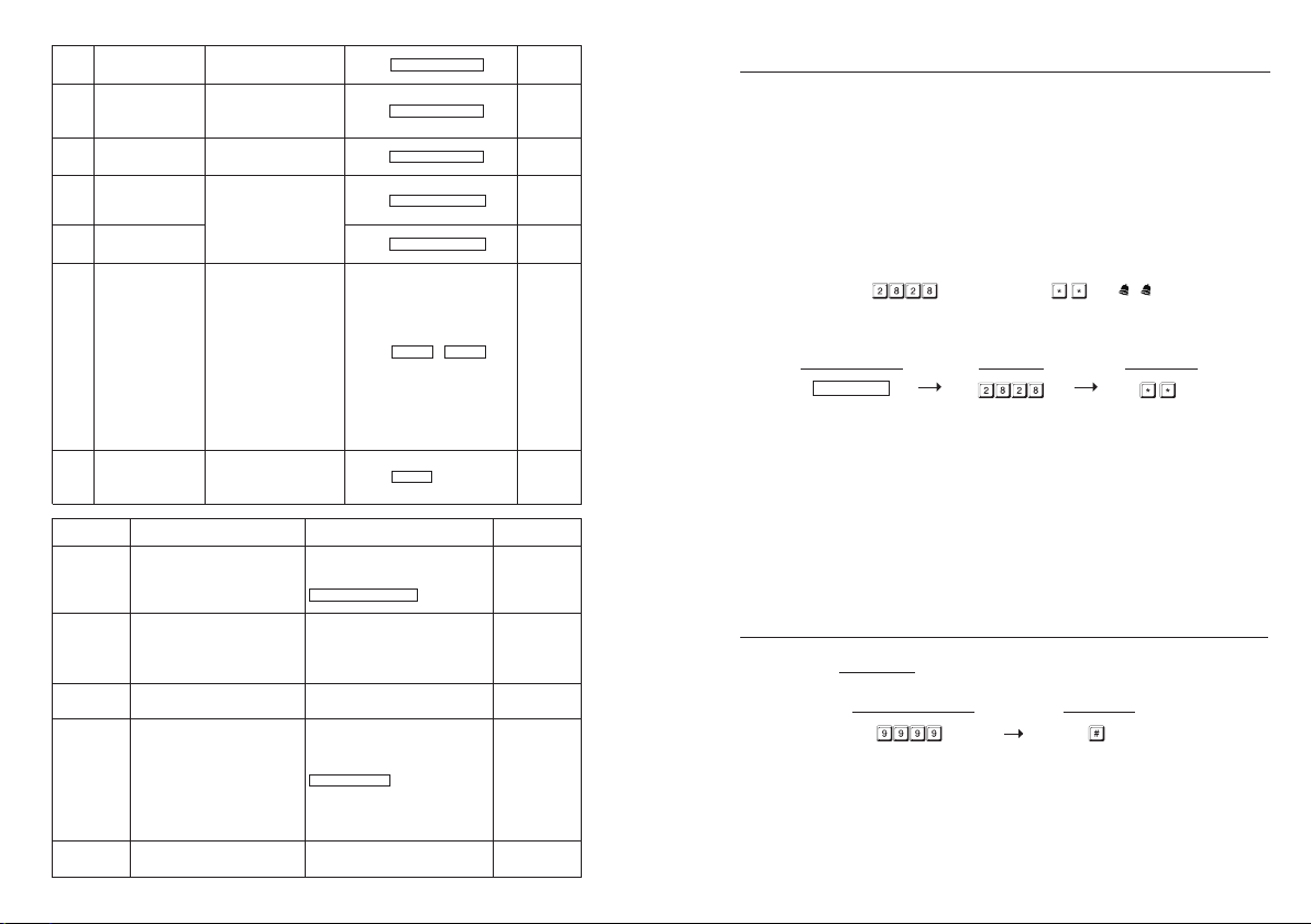
Direct Access to Programming Mode with The “DAP” Code – 2 8 2 8
System Refreshing with “Refreshing Code” --- 9 9 9 9
The Default Values after Refreshing
Master Code
Super User Code
Operation and Functions of The Super User Code
Common User Codes for Output 1 & 2
User Codes/Card For Output 1 & 2
Examples – Programming And Operation
Visitor Codes (For Output 1 Only)
Duress Codes (For Outputs 1 & 2 )
Operation And Function of The Duress Code
Output Modes & Timing for Output 1 and 2
System Real-Time-Clock
Start & Stop Times For Daily Inhibition of Output 1
Personal Safety And System Lock-Out
User Code Entry Mode - Auto or Manual
Pacifier Tones On-Off Selection
Output Operation Announcer
Status LED Flashing On-Off during Standby
Door Forced Open Warning & Timing
Door Propped-Up Warning & The Delay Time
Intelligent Egress Button – An Unique Feature of A Contemporary Keypad
Where And Why “Going Out” Needs Attention
Egress Delay , Warning And Alarm
······································································································································· 4
················································································································································ 4
·················································································· 5
···································································································································· 6
········································································································································· 7
············································································································································ 7
··············································································································· 8-10
································································································································ 11
······················································································································· 11
··········································································································· 11
················································································································· 11
····························································································· 12-13
·············································································································· 12
························································································· 12-13
····················································································································· 13
·································································································· 14-42
···························································································································· 14
·········································································· 14
························································· 15
··········································································· 15
········································································································· 16
·········································································································································· 17
···································································································································· 17
········································································ 18-19
······························································································· 20
···································································································· 21
·························································································· 22-24
···································································································· 25-26
······························································································· 27-29
················································································ 28-29
······················································································· 30
························································································································· 31
··········································································· 32-33
··································································································· 34
································································································ 35
·············································································································· 35
················································································································· 36
··························································································· 36
···································································································· 37
························································································ 37
········································38-39
·············································································38-39
··································································································· 40-41
Page 3

AUXILIARY INFORMATION
DRY CONTACT
A dry cont
act means that no electricity is connected to it. It is prepared for free connections. The
Relay Output contacts provided in this keypad system are dry contacts.
N.C.
Normall
y Closed, the contact is closed circuit at normal status. It is open circuit when active.
N.O.
l
y Open, the contact is open circuit at normal status. It is closed circuit when active.
Normal
TRANSISTOR OPEN COLLECTOR OUTPUT
open collector output is equivalent to a Normally Open (N.O.) contact referring to ground
An
similar to a relay contact referring to ground. The transistor is normally OFF, and its output
switches to ground (-) when active. The open collector can only provide switching function for
small power but it is usually good enough for controlling of an alarm system. The Duress,
Inter-lock and Key Active/Alarm Outputs of the keypad are open collector outputs.
OPEN COLLECTOR
OUTPUT ----
tches to
Output swi
ground when activated
EQUIVALENT
N.O. CONTACT
OUTPUT ----
Output switches to
ground when activated
Operation Modes
Close The Programming Mode
PROGRAMMING MAKE SIMPLE - For General Users
PROGRAMMING SUMMARY CHART
APPLICATION EXAMPLES
A Stand Alone Door Lock
An Inter-Lock System Using Two Keypads
APPLICATION EXPANSIONS
The Axiliary Readers & Keypad
The Split-decoders
1) Dual-station Access Control Door Lock
2) Multi-station Access Control Door Lock
3) Split-decoded Access Control Door Lock
4) Split-decoded Multi-station Access Control Door Lock
APPLICATION HINTS FOR THE AUXILIARY TERMINALS
AUXILIARY INFORMATION
···································································································································· 42
················································································································ 42
····································································· 43-44
································································································ 45-46
················································································································ 47-48
························································································································ 47
····························································································· 48
············································································································ 49-54
··············································································································· 49
·································································································································· 50
························································································· 51
·························································································· 52
························································································· 53
····················································································································· 58
····································································· 54
································································ 55-57
Page 4

INTRODUCTION
DK-2852 is a sel
the digital keypad and proximity EM card reader in one unit.
The keypad has been designed for full feature stand alone access control applications. It is
expandable to work with an optional decoder (DA-2800 or DA-2801) for high security split-decoded
operation. It is also compatible with the auxiliary card reader (AR-2802) and the auxiliary keypad
readers (AR-2806, AR-2807 and AR-2809) for upgrading a stand alone or split-decoded system to
multi-station operation.
The keypad is ideally for door strike and alarm arm-disarm controls. It is also a programmable
industrial timer (from 1 second to over 24 hours) for automatic operator system.
f-contained two output relay , vandal resistant and weatherpr oof keypad. It combines
Two versions are available for DK-2852. They are denoted with a suffix letter “C” & “D”
DK-2852C (Standard Version):
Output Relay 1 – 5A Rating N.C. & N.O. Contacts for Door Lock Actuation Control
Output Relay 2 – 1A Rating N.C. & N.O. Contacts for Auxiliary Device Control
DK-2852D (Door Bell Button Version):
Output Relay 1 – 5A Rating N.C. & N.O. Contacts for Door Lock Actuation Control
Output Relay 2 – 1A Rating N.C. & N.O. Contacts for External Door Bell Actuation Control
FEATURES
A member of the Tri- Tech series keypads compatible with the optional controllers & reader keypads
for system expansion
Loaded with the DK-2800 MK-II operation software
Built-in with all the logics for stand alone, split-decoded and multi-station operations
Controls “Going in” with User Codes / Cards and “Going out” with feature programmable egress
button
Independent control for the two output relays with programming timer (DK-2852C)
Total 1,100 User Codes / Cards for controlling of the two outputs (DK-2852C)
Indoor or outdoor installation with IP-66 all weather ingress protection
Stainless steel faceplate combines with die-casting metal back-lit key buttons
Vandal resistant die-casting metal housing for surface or gooseneck mounting
(F) OUTPUT 2 -- Door Bell Button (DK-2852D)
(OPTIONAL)
ELECTRONIC
DOOR CHIME
N.O.
DOOR
BELL
output 2 of the DK-2852D is prepared for
The
triggering a low power door chime. DO NOT
use it as a high voltage power path for a door
bell. The maximum power rating of the
contact is 24V DC/1 Amp.
Connect the N.O. output contact in parallel
with the door bell button.
Package Contents
• One DK-2852 Keypad
• Two EM Cards
• One Pack of Mounting Screws
• One Centre Pin Torx Screw Wrench
• One User Manual
Page 5

(D) DURESS OUTPUT
The
Duress Output switches to (
ON an LED lamp and/ or a small buzzer to notify a guard; or connect it to a 24 hour Normally
Open protection zone of an alarm system.
Only one connection option is recommended. Make sure that the sink current does not
exceed the maximum rating of 100mA.
-
) groun
d when duress code is entered. You may use it to turn
(E) OUTPUT 2 (DK-2852C)
( i ) Shunting an N.C. Zone
OPTIONAL DEVICES FOR SYSTEM EXPANSION
The Optional Decoders Available for Split-decoded Operation
– Full Feature Decoder with RF Remote Control
DA-2800
DA-2801 – Full Feature Decoder
The Auxiliary Reader / Keypad Available for Multi-station Operation
AR-2802S or A – EM Card Reader
AR-2806S or A – EM Card Reader with Digital Keypad
AR-2807S or A -- EM Card Reader with Digital Keypad
AR-2809S
Remark:
ffix letter “S” stands for standard version and “A” stands for advanced version. The advanced
The su
version possesses the standand features and also provides Wiegand and RS-232 data outputs for the
custom projects with external controller and PC.
ar
d Reader with Digital Keypad
-- EM C
Please contact your local agent for the optional devices.
Use the Normally
alarm system.
Set output contact to Start / Stop Mode (Programming Option 52, Output Mode=0).
( ii ) Alarm System Arm-Disarm Control
Use the (N.O.) or (N.C.) output contact to make arm-disarm control of an alarm system.
Consult your alarm control panel manual for the appropriate output contact for arm-disarm control.
Usually set output 2 to Momentary mode (Programming Option 521, Location 52, Output Mode=1) for
multi station systems and Start / Stop mode (Programming Option 520, Location 52, Output Mode=0)
for single station systems.
Open (N.O.) output contact to shunt a Normally Closed (N.C.) protection zone of an
Page 6

SPECIFICATIONS
Operating Voltage:
/DC, Auto adjusting
12V-24V AC
Operating Current:
62mA (quiescent)
30mA (quiescent) to 61mA@24VDC
Storage and Operation Temperature:
-20 C
Storage and Operation Humidity:
5-95% r
Working Environment & Ingress Protection:
All weather
Number of Users:
Output 1
Output 2 – 100 (Codes and/or Cards) + 10 Duress Codes (DK-2852C)
Proximity Card:
Standard EM
Number of Visitor Codes:
50, pr
Timings for Code Entry and Card Reading:
10 seconds waiting for next digit entry
30 seconds waiting for code entry after card reading
The Timers:
1-99,999 Seconds (Over 24 Hours possibl
Egress Button:
Programmable
Momentary or Holding Contact for Exit Delay
Input Sensing Terminals:
a) Door posit
Output Control Terminals:
Transistor
a) Duress, b) Key Active, c) Inter-lock
Output Contact Ratings:
Output R
Output Relay 2 – N.C. & N.O. dry contacts, 1A/24VDC Max.
Tamper Switch – N.C. dry contact, 50mA/24VDC Max.
Dimensions:
125(H) X 79(W)
Weight:
520g net
Housing:
Die-C
ast Aluminum, Powder-paint coating
Faceplate Material:
1.5mm stai
to 130mA@12VDC
to +70 C
elative humidity non-condensing
, IP-66
– 1,000 (Codes and/or Cards) + 50 Duress Codes
Card or Keyfob, 125Khz
ogrammable for one time or with time limit
e) Independent Programmable Timers for O/P 1 & 2
for Instant, Delay with Warning
ion, b) Egress, c) O/P 1 inhibit
Open Collector 24VDC/100mA sink Max for the following outputs
elay 1 – N.C. & N.O. dry contacts, 5A/24VDC Max.
X 46/54(D)mm
nless steel
APPLICATION HINTS FOR THE AUXILIARY TERMINALS
(A) TAMPER N.C.
(B) DOOR SENS
SENS
DOOR
(–)
GND
With
the help of a Normally Closed
door position sensor (usually a
magnetic door switch) on the door to
set up the following functions:
The tamper switch
keypad is secured on gang box. It is open when
the keypad is removed from the gang box. To
prevent sabotage, connect these terminals in
series with a 24 hour N.C. protection zone of an
alarm system if required.
Door Auto Relock -- The system will
immediately relock the door after
has been gained to prevent "tailgate" entries.
Door Forced-ope n Alarm -- The keypad will
generate alarm instantly if the door is forced to
open. Enable the function at Location 80.
Door P ropped-up A larm -- The keypad will
generate alarm if the door is left open longer
than the pre-set delay time. Enable the function
at Location 81.
Inter-lock Control -- When the door is open,the
interlock output of the keypad will give a (
command to stop the other keypad in an
inter-lock system.
is Normally Closed while the
a valid access
-
)
(C) KEY ACTIVE
(a)
The
Key Active Output switches to (-) ground
for 10 seconds whenever a key is touched.
You may use it to turn ON an LED lamp and
/or a small buzzer to notify a guard; or
to energize a relay to switch ON lights or
trigger an CCTV Camera to start recording.
Make sure that the relay for switching ON
lights has high enough isolation between
high voltage and low voltage to prevent
damage of the keypad.
Only one connection option is recommended.
Make sure the sink current does not exceed
the maximum rating of 100mA.
External power supply and isolation relay
are strictly necessary in driving high power
device, such as lights.
(b)
Page 7

4) Split-decoded Multi-station Access Control Door Lock
Description
This
is an expansion of application (3). The DK-2852 is expandable to a multi-station system in
Split-decoded operation. It is compatible with the auxiliary readers AR-2802 and the auxiliary
reader-keypads AR-2806, AR-2807 & AR-2809. Total 3 auxiliary readers or reader-keypads can
be connected in parallel with the Data I/O Bus. They provide the same functions like the master
keypad in using cards and user codes. The DK-2852 that is the server of the system manages
the data with its Data I/O Bus among the associated devices. This approach gives high security
in sabotage prevention and user convenience.
Note: Make Operation Mode setting of the keypad in “Server Mode” with Location 94 = 1 in
this applicat
ion.
System Connection
TA I/O BUS
DA
(+) POWER SUPPLY
(–) COMMON GND
ELECTRIC L
OUTPUT 1 OUTPUT 2 OUTPUT 3
N.O.
N.C.
OUTPUT RELAY 1
N.O. Output for Fail-secure Lock
N.C. Output for Fail-safe Lock
ELECTRIC LOCK
1N4004
OCK
-
ALARM O/P- KEY ACT O/P- N.O.- COM- N.C.- N.O.- COM- N.C.- N.O.- COM- N.C.- TAMPER- GND
CATHODE
AR-2802/06/07/09
Y READER
AUXILIAR
OR KEYPAD-READER
Wiring Diagram
AR-2802/06/07/09
Y READER
AUXILIAR
OR KEYPAD-READER
DK-2852
(SERVER)
DK-2852 (SERVER)
AD-1312 OR AP-960
DA
TA I/O BUS
(–) COMMON GND
(+) POWER SUPPL
DIGITAL KEYPAD
EGRESS BUTTON
MORE EGRESS
BUTTON CAN
BE CONNECTED
IN PARALLEL
DOOR BELL
BUTTON
DA-2800 OR
DA-2801
(DECODER)
Y
-
12-24V DC
N.O.
N.O.
N.O.
-
KEYPAD PWR- GND
(
)
(
-
)
(
-
)
(
-
)
-
DU OUT- DOOR BELL IN- EG IN- D
ATA I/O
DA-2800 OR DA-2801
(DECODER)
-
DOOR SENS- O/P 1 INHIB- IN
T.
L
(
-
OCK
)
INSTALLATION
ASSEMBLY
2
1
3
4
6
5
9
7
8
0
#
*
LED Indicators
Digital Keyboard
EM Card Reader
PRECAUTIONS
1) Prevent Interference:
Card reader is working at the frequency of 125Khz. Installation precautions are necessary.
The EM
Make su
re the location for installation has no strong low frequency electro-magnetic wave. Especially
in the range of 100-200Khz
If there is more than one keypads with the same operation frequency installed closely in the
location, make sure that they are at least 60cm (2ft) apart from each other to prevention
interference.
2) Prevent Accidental Short Circuit:
the previous experience, most of the damages caused in the installation are accidental touching
In
of the components on circuit board with the wires carrying power. Please be patient to study the
manual to become familiar with the specifications of the system before starting the installations.
Do not apply power to the system while it is in installation.
Check carefully all the wirings are correct before applying power to the system for testing.
Page 8

CONNECTION TERMINALS
BACK-LIT JUMPER
CONNECTION
TERMINALS
1 - 2 : 12 - 24V AC/DC (Power Input T
Connect to 12-24V AC or DC power supply. The (-) supply and (-) GND (terminals 2 & 12) are the
common grounding points of the keypad system. No selection jumper is required for the full input
voltage range. Connect DC power with the (+) and (-) polarity indicated; and there is no polarity
discrimination for AC power input.
erminal)
3 - 4 - 5 : OUTPUT 1 (Output Relay 1)
5 Amp relay dry contact controlled by the Group 1 User Codes/Cards, recommended for door strike.
Terminal 3 is Normally Closed (N.C.), terminal 5 is Normally Open (N.O.) and terminal 4 is the
common point of the two contacts. Use N.C. output for Fail-safe locking device; and N.O. output for
Fail-secure locking device. The relay is programmable for Start/Stop (toggle) mode or Momentary
timing mode. See programming Location 51 for the details.
6 - 7 - 8: OUTPUT 2 (Output Relay 2)
1 Amp relay dry contact with N.C. and N.O. outputs. T erminal 6 is the N.C.(Normally Closed). terminal
8 is N.O. (Normally Open) and terminal 7 is the common point of the two contacts, which is prepared
for actuating auxiliary device controlled by the keypad; or external door chime actuation controlled
by the bell button. The maximum rating of the relay contacts is 24 VDC/1A.
DK-2852C - Standard Version
The Output relay 2 in DK-2852C is controlled by the Group 2 User Codes and Cards. It is
programmable for Start/Stop (toggle) mode or Momentary Timer mode. See programming Location
52 for the details.
DK-2852D - Door Bell Button Version
The Output relay 2 in DK-2852D is controlled by the door bell button on the keyboard. It is an output
point for actuation of a low voltage external (optional) door chime. The contact point activates as
long as the bell button is pressed
3) Split-decoded Access Control Door Lock
Description
rt from stand-alone operation, the DK-2852 can be up-graded to high security Split-decoded
Apa
operation with a decoder unit DA-2800 or DA-2801. The decoder is inside the house with all the
input and output installations connecting to it. The DK-2852 manages the data in the system
with its Data I/O Bus. The decoder operates the door lock and the appliances directly according
to the commands from the keypad unit. This approach prevents the electric door lock or
appliance be operated due to sabotage at the external keypad.
Note: Make Operation Mode setting of the keypad in “Server Mode” with Location 94 = 1 in
pplication.
this a
System Connection
DK-2852
(SERVER)
DA
TA I/O BUS
(+) POWER SUPPLY
(–) COMMON GND
DA-2800 OR
DA-2801
(DECODER)
ELECTRIC L
OCK
Wiring Diagram
DK-2852 (SERVER)
NOTE:
Connect the 1N4004 as close as possible to the lock in
parallel with the lock power terminals of the lock to absorb
the back EMF to prevent it from damaging the keypad. The
1N4004 is not required if the electric lock is AC operated.
o avoid Electro-Static-Discharge from interfering with the
T
operation of the keypad, always ground the (-) terminal of
the keypad to earth.
Always connect DOOR SENSOR terminal to (-) ground if not
used.
Always connect TAMPER terminal to (-) ground if not used.
Make 3-wire Connection (+, -, DATA I/O) to the keypad in
the DK-2800 series. More than one keypads can be
connected in parallel.
DA-2800 OR DA-2801
(DECODE)
AD-1312 OR AP
TA I/O BUS
DA
(–) COMMON GND
(+) POWER SUPPLY
DIGITAL KEYPAD
EGRESS BUTTON
MORE EGRESS
BUTTON CAN
BE CONNECTED
IN PARALLEL
DOOR BELL
BUTTON
-
-
-
-
-
-
DOOR SENS- O/P 1 INHIB- IN
DU OUT- DOOR BELL IN
EG IN- D
KEY
GND
12-24V DC
ATA I/O
T.
L
P
(
AD PW
)
R
-960
(
-
)
N.O.
(
-
)
N.O.
-
)
(
N.O.
(
-
OC
)
K
-
N.O.- COM- N.C.- N.O.- COM- N.C.- TAMPER- GND
OUTPUT 1 OUTPUT 2 OUTPUT 3
N.O.
N.C.
OUTPUT RELAY 1
N.O. Output for Fail-secure Lock
N.C. Output for Fail-safe Lock
ELECTRIC LOCK
1N4004
-
ALARM O/P- KEY ACT O/P- N.O.- COM- N.C
.
CATHODE
Page 9

2) Multi-station Access Control Door Lock
Description
This is an expansion of application (1). The DK-2852 is expandable to a multi-station system for
user convenience with the auxiliary readers AR-2802 and/or the auxiliary reader-keypads
AR-2806, AR-2807 &r AR-2809. Total 3 auxiliary readers or reader-k eypads can be connected in
parallel with the Data I/O Bus and they provide the same functions like the master keypad in
using cards and user codes.
Note: Keep Operation Mode setting of the keypad in “Keypad Mode (default)” with Location
94= 0 in th
is application.
System Connection
DA
TA I/O BUS
(+) POWER SUPPLY
(–) COMMON GND
ELECTRIC LOCK
AR-2806 OR
AR
-2807 OR
AR-2809
(AUXILIARY KEYPAD-READER)
AR-2802S OR
AR-2802A
(AUXILIARY READER)
DK-2852
(MASTER KEYP
AD)
Wiring Diagram
AR-2806 OR
AR
AR-2809
(+) (–)
12-24V DC
-2807 OR
TAMPER
DATA
I/O
AR-2802S OR
-2802A
AR
LED
N.C.
12-24V DC
LED
N.C.
I/O
TAMPER
DATA
(+) (–)
DK-2852
AD-1312 OR AP-960
9 : EG IN ( Egress Input)
Normal
ly Open (N.O.) input terminal referring to (-) ground. With the help of connecting a
A
normally open button to activate Output 1 for door opening like using Codes/Cards.
Egress button is usually put inside the house near the door. More than one egress buttons can be
connected in parallel to this terminal. Leave this terminal open if not used.
See Programming Locations 90 for more information about the Egress Button with programmable
features.
10 : KEY ACT O/P (Keypad Active Output)
An NPN transistor open collector output with maximum power rating of 24VDC/100mA sink. It is
equivalent to an N.O. (Normally Open) terminal referring to ground. It can be used to drive small
power device, such as a relay or a low power control point for other equipment.
11 : DU OUT (Duress Output)
An NPN transistor open collector output with maximum power rating of 24VDC/100mA sink. It is
equivalent to an N.O. (Normally Open) terminal switching to (-) ground after the Duress Code is
entered. Use it to trigger an alarm zone of a security system, or turn on a buzzer to notify a guard.
12 : (-) GND (Common Ground)
A grounding point of the keypad that is common to terminal 2.
13 : DOOR SENS N.C. (Door Position Sensing Input -- Normally Close)
A Normally Closed (N.C.) sensing point referring to (-) ground, with the help of a normally closed
magnetic contact monitors the open or close status of the door. It initiates the following functions
for the system. Connect it with jumper to (-) Ground if not used.
a) Door Auto Re-lock
The system immediately re-locks the door after it is re-closed before the end of the programmed
time for output 1. It prevents unwanted “tailgate” entry.
b) Door Forced Open Warning
The keypad generates “door forced open” warning instantly once the door is forced to open
without a valid user Code, Card or egress button. The warning lasts as long as the time
programmed (1-999 sec). It can be stopped with an User Code or card for output 1 at anytime.
See programming Location 80 for the details.
AUXILIARY
KEYPAD-READER
AUXILIARY
READER
DATA I/O BUS
(+) POWER SUPPLY
(–) COMMON GND
EGRESS BUTTON
(INSIDE THE HOUSE)
MORE EGRESS
TONS CAN
BUT
BE CONNECTED
IN PARALLEL
c) Door Propped-up Warning
The keypad generates propped-up warning beeps while the door is left open longer than the
allowable time programmed. The warning will last as long as the door is open until re-closed. See
programming Location 81 for the details.
d) Inter-lock Control
The inter-lock control output always goes to (-) while the door is open, which gives signal to
disable the partner keypad in an inter-lock system. See the Inter-lock terminal 15 description for
more information.
Page 10

14 : O/P 1 INHIBIT N.O
A Normally Open (N.O.) sensing input point for controlling the Output 1, with this terminal
connecting to (-) ground, the Egress Button, the group of User PINs and Cards for Output 1 are
all disabled. It is prepared mainly for the cross wire connection with the “Inter-lock O/P” point of
the partner keypad in an Inter-lock system.
NOTE: The inhibit function does not govern the Duress Codes and the Super User Codes. They are
alwa
15 : INTER-LOCK O/P (Inter-lock Control Output)
An NPN transistor open collector output with maximum power rating of 24VDC/100mA sink. It is OFF
at normal condition and it switches to (-) ground immediately for the first 5 seconds after keying in
a valid User Code or reading a card to operate Output 1, then, it will keep tying to (-) ground during
the Door Position Sensor is open circuit due to door opening. Use this output point to make cross
wire connection with the partner keypad’s “O/P 1 Inhibit” point in an Inter-lock system to prevent
both doors can be opened at the same time.
An Inter-lock System:
An inter-lock system is a two-door system that always allows only one of the doors to open during
the operation. While one of the doors is opened, the other door keeps close until the open door is
re-closed. It prevents the unauthorized people dashing into a protected area while the doors are in
use.
An inter-lock system needs two keypads and two door position sensing switches for the two doors.
16 - 17 : TAMPER N.C. (Tamper Switch Normally Closed Contact)
A normally closed dry contact while the keypad is secured on its box. It is open while keypad is
separated from the box. Connect this N.C. terminal to the 24 hour protection zone of an alarm
system if necessary.
18 : DATA I/O PORT (Data Communication Bus)
Data I/O port is prepared for setting up a data bus for the connection of the auxiliary reader-keypads
and the split-decoder in system expansion. See the examples in “Application Expansions” section for
the details.
. (Output 1 Inhibit Control Input – Normally Open)
ys valid.
1) Dual-station Access Control Door Lock
Description
can select an auxiliary reader AR-2802 or an auxiliary reader-keypad AR-2806, AR-2807
Owner
or AR-2809 and connect it with the master keypad DK-2852 to expand the system with
dual-station for user convenience. Simply connect the reader or the reader-keypad in parallel
with the Data I/O Bus of the master keypad. The auxiliary reader accepts all the cards that are
programmed in the master keypad. If it is an auxiliary reader-keypad it accepts cards and user
codes like the master keypad.
Note: Keep Operation Mode setting of the keypad in “Keypad Mode (default)” with Location
94 = 0 in this a
pplication.
System Connection
TA I/O BUS
DA
(+) POWER SUPPLY
(–) COMMON GND
ELECTRIC LOCK
AR-2802 S or A
(AUXILIARY READER)
-2852
DK
(MASTER KEYP
AD)
Wiring Diagram
AR-2802S AUXILAR
OR
AR-2802A
(+) (–)
12-24V DC
Y READER
DK-2852
DATA
AMPER
T
LED
I/O
N. C.
-960
AD-1312 OR AP
TA I/O BUS
DA
(+) POWER SUPPLY
(–) COMMON GND
EGRESS BUTTON
(INSIDE THE HOUSE)
MORE EGRESS
TONS CAN
BUT
BE CONNECTED
IN PARALLEL
Dual-Station Access Control Door Lock
Page 11
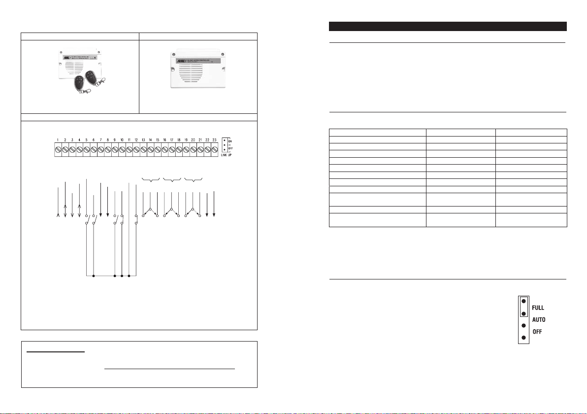
The Split-decoders (Optional)
A-2800
DA-2801D
ON-BOARD LED INDICATORS
RED / GREEN (Right) ---
AMBER (Centre) ---------
RED (Left)
----------
It l
and flashing during inhibition paused.
It flashes in Standby. It shows the system status in synchronization
with the beep tones. The standby flashing can be OFF with
programming. See Location 73 for the details.
It lights up in Red for output 2 activation.
ights up in Green for Output 1 activation; Red for Output 1 inhibited
OTHER FACILITIES
Standard DecoderDecoder with RF Remote Control
Connection Terminal
-
-
-
-
-
-
-
12-24V DC
POWER INPUT FOR SYSTEM
DATA I/O
GND(
EG IN
KEYPAD PWR
)
INPUT/OUTPUT FOR SPLIT-DECODED SIGNALS
POWER OUTPUT FOR KEYPADS
COMMON GROUND
N.O. S
W
DOOR BELL IN
DU OUT
OPEN COLLECTOR OUTPUT
N.
O. SW
-
-
-
-
GND(
O/P 1 INHI
INT. LOCK
DOOR SENS
)
B
OPEN COLLECTOR OUTPUT
COMMON GROUN
N.C. SW
N.O. S
W
D
-
-
-
-
-
-
T
N.C.
AMPER
OUTPUT 1 OUTPUT 2 OUTPUT 3
FOR DOOR STRIKE
N.C. SW
COM
5A RELAY
DRY CONTACTS
N.O.
N.C.- N.O.
COM
1A RELAY
FOR AU
XILIARY CONTROL
DRY CONTACTS
-
-
-
-
N.O
COM
KEY ACT O/P
N.C.
.
OPEN COLLECTOR OUTPUT
1A RELAY DRY CONTACTS
FOR AUXILIARY CONTROL
-
AL
ARM O/P
OPEN COLLECTOR OUTPUT
IMPORTANT NOTE
The optional Auxiliary Readers, Reader-keypads and Split-decoders are DC
operation. It is necessary to power the whole system with DC power supply if the
eypad is working with them for system expansion, even it is an AC/DC
Master K
Version keypad
PACIFIER TONES & THE LED SIGNALS
zzer and the amber LED indicator give following tones and signals respectively for system
The bu
status:
1) In
2) Successful Key Entry 1 Beep 1 Flash
3) Successful Code / Card Entry 2 Beeps 2 Flashes
4) Unsuccessful Code / Card Entry 5 Beeps 5 Flashes
5) Power Up Delay Continuous Beeps Continuous Flashes
6) Output Relay Activation ** 1 Second Long Beep
7) In Standby *** ----- 1 Flash in 1 Second Interval
8) System Refreshing ----- Fast Flashes for 2.5 Minutes
System
power failure
NOTE:
*
* *
* * *
JUMPER FOR BACK
1) Full Back-lit
2) Auto Back-lit ---
3) OFF ---
STATUS TONES * AMBER LED
Programming Mode ----- ON
-----
1 Long Beep
Card or Code Al
All Pacifier Tones can be ON or OFF through the programming option at Location 71
The Output Relay Activation beep can be selected through the programming option at
Location 72
The Standby flashing can be ON or OFF through the programming option at Location 73
ready Stored in
-LIT SELECTION
---
The keypad gives dim backlit in standby. It
turns to full backlit when a key button is
pressed, then back to dim backlit 10
seconds after the last key button is
pressed.
The backlit is OFF in standby. It turns to
full backlit when a key button is pressed,
then back to OFF 10 seconds after the last
key button is pressed.
)9
10) Keypad link-up with Decoder Failed
Continuous 3 Fast Beeps
11) Real -time-clock stopped after
/5 secs
Back-lit function disabled.
-----
-----
-----
Continuous 1 Beep/5 secs
BACK-LIT
JUMPER
Page 12
TION FOR PROGRAMMING
PREPARA
A) CRITERIA FOR CODES AND CARDS
1) Prime Codes
The prime
codes include the a) User Codes, b) Master Code, c) Duress Codes, d) Super User Codes,
e) Common User Codes and f) Visitor Codes. All these codes MUST be unique. It is not allowed to
repeat a prime code for second function.
All the codes in this system can be 4-8 digits for Manual Entry Mode. The codes must be in the same
digit length with the Master Codes for Auto Entry Mode. See Location 70 for the details.
2) Prime Cards
All the User Cards are prime cards. They are not allowed to program for second function. e.g. a card
was programmed for operating output 1 is not allowed for output 2.
The cards used in this system are 125Khz proximity EM cards.
3) Secondary User Codes
A Secondary User Code is prepared to enhance the security of an user card, which is a code put after
a card. The keypad requires both card and code are correct to grant an entry. The secondary code
can be repeatedly used for a group of cards; or proprietary with one code for one card.
NOTE:
The keypad will reject repeated use of prime card or prime code in programming and give one long
beep indication.
APPLICATION EXPANSIONS
Apart
from standard-alone operation, DK-2852 is expandable to be a Multi-station System or a High
Security Multi-station Split-decoded System with its Data I/O Bus for the connection of the optional
auxiliary keypad(s) and decoder. The wiring is very simple. Just connect all the related devices in
parallel with the Data I/O Bus. The DK-2852 is the server that manages the data among them.
A Multi-station System provides higher security in access control and user convenience to operate an
electric lock at different locations. Such as a dual keypad system for area needs controlling of going
in and going out with user codes or EM cards.
A Split-decoded keypad system increases the overall security with keypad(s) installing outside and
decoder installing inside. It prevents the door can be opened due to sabotage at the external
keypad(s). A Split-decoded system is also compatible with the auxiliary keypads for multi-station
operation. It is a perfect system for overall higher security and user convenience.
The application examples here show the connections of the auxiliary keypads and the decoder to the
server keypad. Please contact your local agent for these optional devices if increasing security and
user convenience to the system is required.
The auxiliary reader / keypads and the decoders are compatible with all the keypads in the DK-2800
MK-II series.
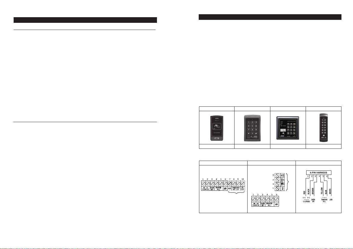
The Axiliary Readers & Keypad (Optional)
AR-2809AR-2807AR-2806AR-2802
B) SECURITY LEVEL OF THE OPERATION MEDIA
The keypad
Location 10, 20 & 30
provides 5 operation Media for owner’s selection of security level. See programming
1) EM Card Only – Operation Media 1
A general way for access control, just simply read a card to open the door. Security level is moderate
but it is user convenient.
2) User Code Only – Operation Media 2
A general way for access control, just simply enter a code to open the door. Security level is
moderate but it is user convenient.
3) EM Card + Common User Code – Operation Media 4
The keypad requires both Card and Common User Code are correct to grant an entry . Common User
Code is an user code for all the cards. Two media ar e used in door control. The security level is better
than just card or user code alone.
This operation mode can also report Duress Alarm by keying the duress code instead of common
user code in emergency when the user is forced to open the door.
4) EM Card + Group Secondary User Code – Operation Media 3
A secondary user code can be repeatedly used for a group of cards in a department. Owner can
make a proprietary department code for each department in a company. Only the staff of the
department holding a card and knowing the code is accepted to enter. This approach increases the
departmental security and prevents a lost card picked up by other group of people in the company
to open the door.
This operation mode can also report Duress Alarm by keying the duress code instead of common
user code in emergency when the user is forced to open the door.
Aux. Reader-K
Connection Terminal
ONLY
Version"A"
Y
Version"A" ONL
The version"A" auxiliary reader keypads are available, which provide Wiegand and RS-232 data
outputs.
eypadAux. Reader-KeypadAux. Reader-KeypadAux. Reader
AR-2809AR-2806AR-2802 and AR-2807
Page 13
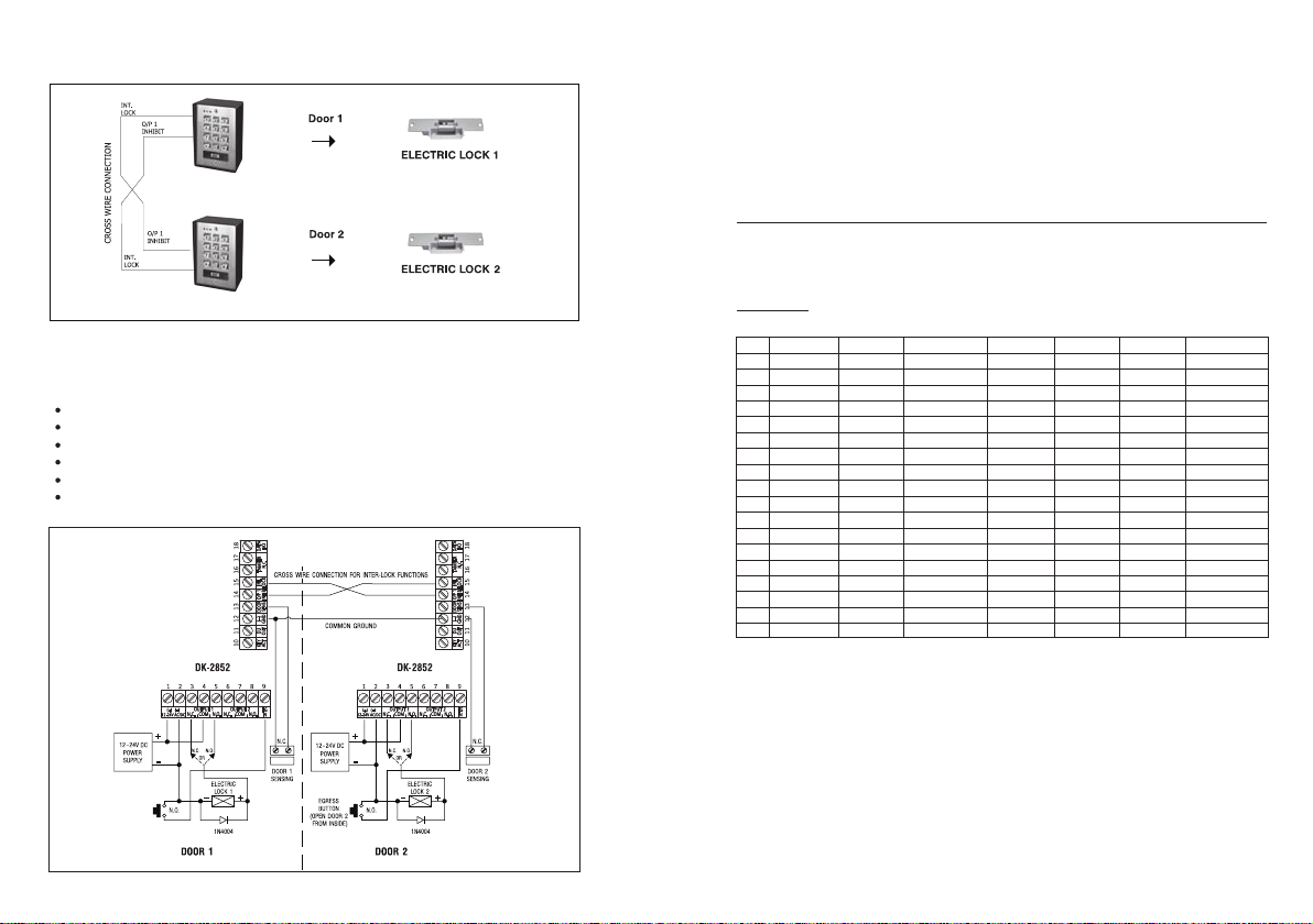
2) INTER-LOCK SYSTEM USING TWO KEYPADS
DK-2852
DK
-2852
er-lock system needs two door controllers. This application example uses two keypads with
An int
simple cross wire connection on their "Output 1 Inhibit" and "Inter-lock Control Output" terminals.
It is necessary to link up the "(-) GND" terminals of the two keypads as common ground to achieve
the inter-lock logical functions.
Use keypad to open the door from outside
Press egress button to open the door from inside
Connect the door magnetic sensors on the doors to monitor their positions
While door 1 is open, then, door 2 is forced to keep close, or vice versa
Use N.O. Relay output for fail-secure lock; and N.C. output for fail-safe lock
Please also see the "NOTE" stated in the Application Example (1)
5) EM Card + Proprietary Secondary User Code – Operation Media 3
The keypad accepts programming with each card having its own proprietary user code to work. It
prevents any other people can use the lost card to open the door. Card with proprietary user code
approach is ideal for the area that high security is the main concern.
This operation mode can also report Duress Alarm by keying in the duress code instead of
Secondary user code in emergency when the user is forced to open the door.
C) LIST OF USER INFORMA
eypad can accommodate up to 1,200 users (codes / cards). To avoid confusion and for
The k
programming convenience, it is suggested to make a list recording of the user information. It helps
the owner to program the user codes and cards smoothly and to trace them afterwards in the future.
Here is a suggested format of the list.
TION
List of Users (See page 21-24 for reference)
Example:
User
1
2
3
4
5
6
7
8
9
10
11
12
13
14
15
16
--
1,000
Name Location
John
May
Tom
Tracy
10
20
10
10
Media
1
2
3
4
User ID
001
001
002
003
Code
/
1234
24680
Common
Card # Remark
001
002
003
Output 1
Output 2
/
Output 1
Output 1
EGRESS
BUT
TON
(OPEN DOOR 1
FROM INSIDE)
Page 14
PROGRAMMING & OPERATION
POWER-UP THE KEYP
eypad gives power-up delay of 1 minute after power has been applied. It is the time frame
The k
designed for setting the keypad to programming mode with DAP code. See the details of “DAP
CODE – 2 8 2 8” below.
1) The keypad gives continuous beeps for 1 minute after power-up.
AD
APPLICATION EXAMPLES
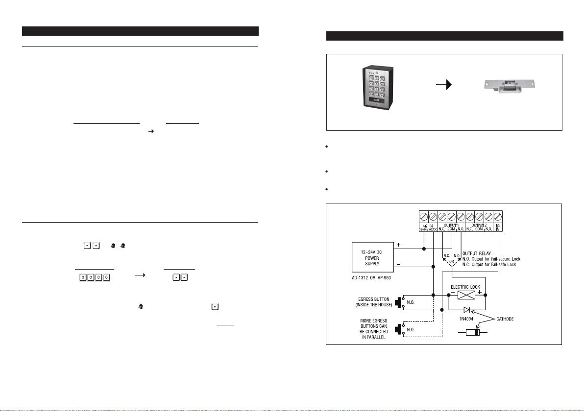
1) STAND ALONE DOOR LOCK
2) The power-up delay can be stopped instantly with if the delay beep is found annoying
and setting the keypad to programming mode with DAP code is not required.
POWER-UP DELAY STOP VALIDATION
3) The keypad will set itself to Normal Operation Mode automatically after the 1 minute power-up
delay expired or it is stopped with .
SET KEYPAD IN PROGRAMMING MODE WITH MASTER CODE
It is always necessary to set the keypad in programming mode for feature programming
The keypad is in normal operation after power-up delay. Set it in programming mode with Master
Code and validate it with or .
NOTE:
a) For th
b) For the owner’s convenience in programming at the first time, a Master Code 0 0 0 0 has been
put into the keypad before exit-factory. It is NOT a default code. For security reason, owner
should program a personal Master Code to replace it after the keypad is owned.
c) The Mains LED (amber) is ON after the keypad confirms it in programming mode with 2 beeps.
d) DO NOT turn off power while the keypad is in programming mode. Otherwise, it may cause error
to the data in memory.
MASTER CODE V
ose keypads with door bell button, the button is equivalent to the button.
ALIDATION
ELECTRIC L
DK-2852
NOTE:
Connect t
he 1N4004 as close as possible to the lock in parallel with the lock power terminals of the
lock to absorb the back EMF to prevent it from damaging the keypad. The 1N4004 is not required
if the electric lock is AC operated.
To avoid Electr o-Static-Discharge from interf ering with the operation of the keypad, alw ays ground
the (-) terminal of the keypad to earth.
Always connect DOOR SENSOR terminal to (-) ground if not used.
1 2 3 4 5 6 7 8 9
DK-2852
(+) (–)
12-24V AC/DC
OUTPUT 1
N.C
. COM N.O.
OUTPUT 2
N.C
. COM N.O.
OCK
EG
IN
Page 15
7 1
7 2
7 3
8 0
8 1
9 0
9 4
SYSTEM
CODES
0 0
9 9 9 9
2 8 2 8
0 9 9 9
* *
Pacifier Tone
ON-OFF
nounc
er
Output An
ashing
Standby LED Fl
Door For
ced Open
Warning & Time
Propped-up Warnin
Time
Egress Delay Warni
Operation M
0 0
g &
ng
ode
FUNCTION CODE ENTRY RESULTS
Factory Set Master Code for User to set
system in programming Mode at the first
time.
THIS IS NOT A PERMANENT SYSTEM
CODE & IT IS CHANGED IF A NEW
MASTER CODE IS PROGRAMMED.
REFRESH CODE -- Refresh the system
and set all its function back to default
values.
DAP CODE-- Direct access to
programming mode. Valid only in the
power-up delay period
USER Codes / Cards whole group
clearing Code for the selected Location
LOCATIONS:
10--- User Group 1
20--- User Group 2
40--- Vistor Group
41--- Duress Group 1
42--- Duress Group 2
Exit
Programming Code
FUNCTION MODE:
0---OFF
1---ON
FUNCTION MODE:
Notification
0---NO
1---1 Second Long Beep
2---2 Short Beeps
FUNCTION MODE:
0---OFF
1---ON
FUNCTION MODE / TIME:
0---OFF
Seconds
1-999
CODE 1 - FUNCTION
MODE:
1---Momentary
2---Momentary, with
warning
4---Hold Contact, No
warning
5---Hold Contact, with
warning
CODE 2
0---No Del
1-99 Seconds
FUNCTION MODE:
0---Keypad Mode
1---Server M
, No warning
-
DELAY TIME:
ay
ode
OR
NEW MASTER CODE
LOCATION NO.
FUNCTION MODE
FUNCTION MODE
FUNCTION MODE
FUNCTION / TIME
FUNCTION / TIME
CODE 1 CODE 2
MODE
System in
Programming M
All programmed
a are cleared
dat
and back to the
default values
except the Master
System in
Programming M
Whole group
of users
selected location
are cleared
The system back
to
normal opration
after programming
= 1,
Mode
Pacifier Tone
ON
Mode
= 1
1 Second
Long Beep
Mode
= 1,
Flashing ON
Mode = 0,
Forced
Door
Open
Warning OFF
M
ode = 0,
Propped-up
arning OFF
W
Mode = 1
omentary,
M
No warning
TIME = 0
No Delay
Mode = 0
Keypad
ode
M
ode
Code
ode
in the
DIRECT ACCESS TO PROGRAMMING MODE WITH “D
In case the Master Code is forgotten, apply the following procedures precisely to set keypad
into programming mode with DAP code:
1)
witch OFF all the power for 1 minute to ensure that the keypad is fully discharged.
S
2)
Switch ON power again. The keypad is in Power-up Mode for 1 minute. The buzzer gives
continuous beeps and the Status LED is flashing. This is the only time frame to accept the DAP
code.
3)
Press the Egress Button (the button connecting accross EG IN, (Terminal 9) and (-)GND,
(Terminal 15) once to enable the keypad for accepting DAP code. The power-up beep stops after
the Egress Button is pressed.
4)
Key in the DAP code and validate it with (or ). The Status LED is
ON and the keypad is in programming mode like using Master Code. It is ready to accept new
programming data as long as you like until exit programming mode.
EGRESS BUT
TON DAP CODE VALIDATION
AP” CODE -- 2 8 2 8
PRESS ONCE
ogram a new Master Code to replace the old one. See “Record A Master Code”
5) To pr
NOTE:
The keypad will set itself to normal operation mode 1 minute after power-up if the Egress Button is
not pressed and the DAP code is not keyed in. To set keypad back to power-up mode, repeat
procedures 1-4.
“Location
01” for the details.
SYSTEM REFRESHING WITH “REFRESHING CODE” --- 9 9 9 9
The keypad can be r
values except the Master Code.
NOTE:
e sure that system refreshing is really required before entering the refreshing code.
Mak
a)
Refreshing takes few minutes. The status LED (amber) keeps flashing during refreshing.
b)
The keypad is back to its default value after refreshing. Re-program of the desired values are
c)
necessary.
efreshed by cleaning all the programmed old data and set it back to default
REFRESHING CODE V
ALIDATION
stated at
Page 16
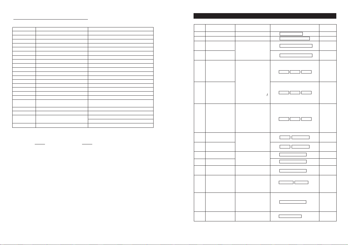
THE DEFAULT VALUES AFTER REFRESHING
LOCATION PARAMETERS DEFAULT FUNCTIONS & VALUES
NOTE:
The DAP Code
It can not be changed in any ways.
Master Code 0 0 0 0 Factory Set, Not a default value *
0 1
0 2 Super User Codes Nil ----- User Program Required
0 3 Common User Code 1 Nil ----- User Program Required
0 4 Common User Code 2 Nil ----- User Program Required
1 0 User Codes & Cards for O/P 1 Nil ----- User Program Required
2 0 User Codes & Cards for O/P 2 Nil ----- User Program Required
4 0 Visitor Codes Nil ----- User Program Required
4 1 Duress Code for O/P 1 Nil ----- User Program Required
4 2 Duress Code for O/P 2 Nil ----- User Program Required
5 1 O/P Mode of The O/P 1 Time = 5 Sec, Momentary
5 2 O/P Mode of The O/P 2 Time = 5 Sec, Momentary
5 5 System Real-Time-Clock Nil ----- User Program Required
5 6 Start & Stop Time Nil ----- User Program Required
6 0 Personal Safety & Lock-out Code = 1, 10 False Code/Card Lock-out 60 Sec
7 0 User Code Entry Mode Code = 2, Manual Entry Mode
7 1
Pacifier Tones ON-OFF Selection
7 2 O/P Operation Announcer
7 3 Status LED Standby Flashing ON-
OFF
8 0 Door Forced Open Warning & Timing Code = 0, Warning Disabled
8 1 Door Propped-up Warning & Delay Code = 0, Warning Disabled
9 0 Egress Delay & Warning Code 1 = 0, Instant, No Delay
9 4
Operation Modes Code = 0,Keypad Mode
Code =
1, Pacifier Tone ON
Code = 1 Sec, Notification Beep ON
Code = 1, Flashing Enabled
1,
Momentary Contact without Warning
Code 2 =
2 8 2 8 and the Refreshing Code 9 9 9 9 are fixed in the operating system program.
LOCATION
FUNCTION
Master Code 4-8 Digits
0 1
per
User
Su
2
0
Common User
0 3
O/P 1
Common User
0 4
O/P 2
ode
C
User
10
20
4 0
4 1
4 2
5 1
5 2
5 5
5 6
0
6
7 0
s /
O/P 1
User
s /
Code
O/P 2
Visitor Code
Duress Code for O/
Duress Code for O/
for O/P 1
O/P Mode
O/P Mode
for O/P 2
Real-Time-Clock
Stop Times
Start &
for Inhibition
Person
Safety &
al
Lock-Up
try Mode
Code
En
PROGRAMMING SUMMARY CHART
ENTRY LIMITS & CODE
OPTIONS
ode
C
Cards for
Cards for
s
Code
Code
Digits
4-8
for
4-8 Digits
for
CODE 1
1---EM
Card
2---Private User Code
3---EM Card+Sec User Code
4---EM Card+Com User Code
5---Deletion of User Code
CODE 2
000-999---Group 1(10)
001-100---Group
CODE 3
CARDS :
4-8 Digits/Cards
CODE 1
01-50
CODE 2
00---One Time
01-99 Hours
CODE 3
4-8 Digits
CODE ID
P 1
CODE ID - O/P 2: 01-10
P 2
DURESS CODE:
OUTPUT MODE & TIME:
0--- Start / Stop
1---99999 Seconds
CURRENT REAL TIME:
00:00-23:
START TIME:
00:00-23:59
STOP TIME:
00:00-23:59
LOCK-UP CODE:
1---10 Trial, Lock-Up 60 Sec.
2---10 Trial, Activates Duress
5-10---5-10 Trial, Lock-Up 15
Minutes
00---No Lock-Up
ENTRY MODE:
1---Auto Mode
2---Manual Mode
-
MEDIA:
USER ID:
-
2(20)
-
USER CODES/
-
VISITOR ID:
-
VALID PERIOD:
-
VISITOR CODE:
-
O/P 1: 01-50
4-8 Digits
59
CODE ENTRY
MASTER CODE
SUPER USER CODE
COMMON USER CODE 1
COMMON USER CODE 2
CODE2 CODE3
CODE1
CODE2 CODE3
CODE1
CODE2 CODE3
CODE1
DURESS CODE
CODE ID
DURESS CODE
CODE ID
O/P MODE & TIME
O/P MODE & TIME
CURRENT TIME
STOP TIMESTART TIME
LOCK-UP CODE
ENTRY MODE
FACTORY
DEFAULT
NIL
NIL
NIL
NIL
NIL
NIL
NIL
NIL
NIL
5 Seconds
Seconds
5
NIL
NIL
Code
= 1,
10 Trials,
Lock-Up 60
Seconds
Mode
=
2, Manual
Mode
Page 17
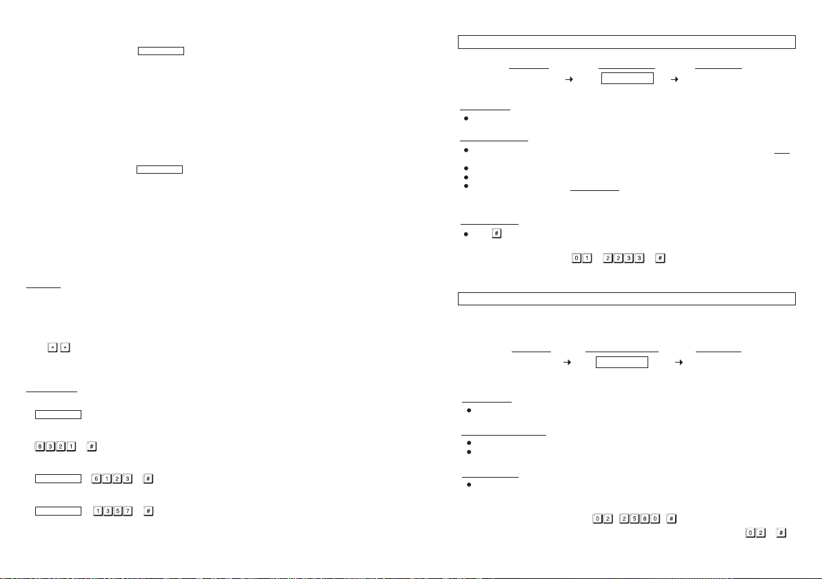
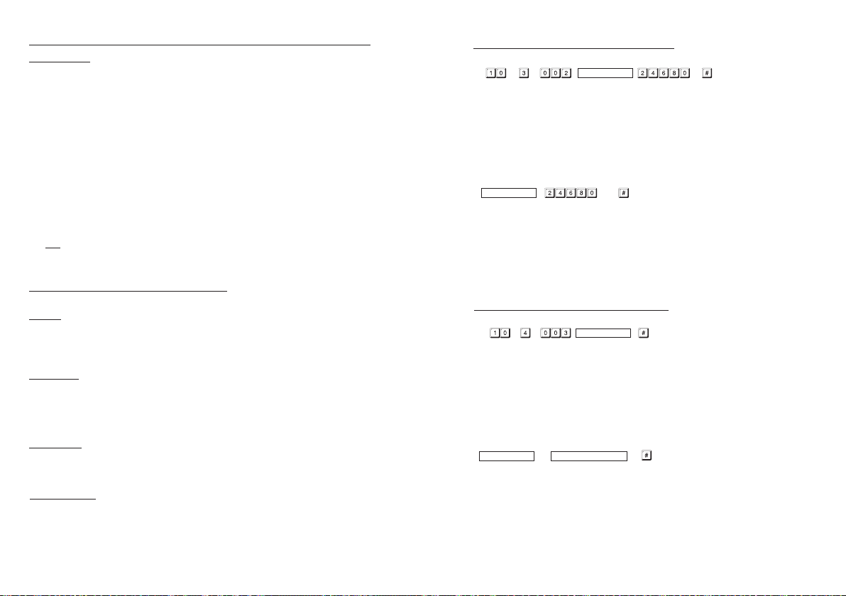
5) Record an “EM Card + User
(a) (b) (c) (d) (e) (f)
(a) 10 = Programming Location for Output 1
(b) 3 = Programming option for EM Card + User
proprietary)
(c) 003 = One
(d) Read Card = Put the Card close to the card reader
(e) 6123 = The User
(f ) # = Confirm the Card+Code is stored, 2 beeps
6) Record an “EM Card + Commom User Code” to Operate The Output 1 for Door Open
(a) 10 = Programming Location for Output 1
(b) 4 = Programming option for EM Card + Common User Code
(c) 004 = One of the 1,000 User IDs for the User
(d) Read Card = Put the Card close to the card reader
(e) # = Confirm the card is read, 2 beeps, the Common User Code goes to this User ID
(f ) A Common User Code (for example: 1 3 5 7) MUST be set at the Programming Location 03
REMARK:
If more User
above with other User IDs, such as 005, 006, 007 --- 999 etc. Total 1,000 users are allowed. See
Programming Location 10 for the details.
7) Close The Programming Mode
---- 2 beeps
The programming mode is closed. The keypad is back to normal operation mode
OPERA
1) Open The Door with EM Card
2) Open The Door with User Code
--- 2 beeps, the door is open
3) Open The Door with EM CARD + User Code
--- 2 beeps, the door is open
4) Open The Door with EM CARD + Common User Code
--- 2 beeps, the door is open
of the 1,000 User IDs for the User
Code
(b)
(a)
automatically
first. Common code can be used for all the EM Cards in this operation mode.
Code
s and
TION
READ CARD
--- 2 beeps, the door is open
READ CARD
READ CARD
Code
” to Operate The Output 1 for Door Open
READ CARD
Code
. (
Code
/Car
be used wi
to
(c)
Cards are required for Output 1, repeat the procedures (3) , (4) , (5) or (6)
th the EM Card. It is for example here only.
READ CARD
(d) (e)
Code
/Car
The User
Code
d from 000-999
d from 000-999
be repeated use or
can
MASTER CODE (Location 01)
LOCATION MASTER CODE VA
8 Digits
(1) LOCATION
Key in Locat
(2) MASTER CODE
(3) VALIDATION
Example:
Set a
ion
Master Code is the authorization code for setting the system to programming mode. It is NOT
an User Code operating the output relays.
The Master Code can be 4 to 8 digits.
When a new master code is keyed in and confirmed, the old master code is replaced.
The master code is also the Link-up Code between the keypad and the optional decoder in
Split-decoded operation.
Press k
ey once. Two-beeps confirms the entry.
Master Code “2 2 3 3” ----
4 to
(2)(1) (3)
LIDATION
SUPER USER CODE (Location 02)
Super User Code has TWO functions. It is prepared to operate the three outputs and make
The
operation of inhibit enable / disable to those outputs.
LOCATION SUPER USER CODE VALIDATION
4
8 Digits
(1) (2) (3)
(1) LOCATION
Key in Location
(2) SUPER USER CODE
The Super User Code can be 4 to 8 digits.
When a new Super User Code is keyed in and confirmed, the old one is replaced.
(3) VALIDATION
Pressing key to confirm code entry.
Example:
Super User Code “2 5 8 0” ----
a) Set a
b) Deleted a Super User Code from memory: Key in the Location number and #. ----
to
Page 18

OPERATION AND FUNCTIONS OF THE SUPER USER CODE
1) Operate Output 1 and 2
The operation
specific output number for the desired Output. The Super User Code can also be used to reset an
operating output timer instantly.
of the Super User Code is just like a normal User Code. Simply key-in the Code with a
PROGRAMMING MAKE SIMPLE – For General Users
This i
s a multi purpose keypad. It has many functions for user’s selection. For those general users
taking the keypad for door strike only, most of the features can be kept in their Def ault values. Only
the User
The keypad accepts 1) Card only, 2)
Code to operate its outputs.
Cards and a private Master Code are required to program.
Code
s /
Code
only,
3) Card +
Code
or 4) Card
+ Common User
---------- Output 1 Activates or Resets
SUPER USER
---------- Output 2 Activates or Resets
SUPER USER
Optional Functions Controlled by Super User Code for Output 1
Apart from controlling of the two outputs 1 and 2; the Super User Code can also be used to enable
the optional functions controlling Output 1 for user convenience or security enhancement.
Super User Code and Egress Button are excluded from any system inhibition and lockup functions;
they are valid for door open at anytime for safety.
2) Override The Door Lock Controlled by Output 1 (Keep Door Un-locked)
The Output 1 is usually for door lock control. In some situations, the door may require un-locked for
a period of time to allow door opening without User Code or EM Card for entry / exit convenience.
This function Starts / Stops in toggle with the following code entry.
SUPER USER
---------- The Door is Un-locked, Start / Stop in Toggle
NOTE :
•
The door is un-lock
•
Do not forget to stop this function after use because the door is un-locked. Also, the system
refuses the optional functions (3) & (4) while Override function comes into effect.
This feature is good for all the “Fail-safe electric locks”.
•
“Fail-secure electric lock” requires power to keep in un-locked condition. It takes high current
•
all the time while the function comes into effect and may cause damage to it. This function is not
recommended for Fail-secure electric lock.
3) Pause The Scheduled Daily Inhibition for Output 1 (T
The scheduled inhibition can be programmed and applied to Output 1 with daily start and stop times.
It can be stopped temporarily if required; such as the staff work overtime after office hours going
into the inhibition period. This function Starts / Stops in toggle with the following code entry. It can
be done before or during the inhibition period.
---------- Door Lock Operation Resumes, Start / Stop in Toggle
SUPER USER
NOTE :
•
The “INHIBIT” LED (R
See
•
CODE
CODE
CODE
ed while the function is enabled. The “Output 1” LED (Green) turns ON.
emporarily Disable The Inhibition)
CODE
ed) is ON in inhibition and turns to Flashing while pause is into effect.
Programming Locations 55 & 56 for more information Daily Inhibition.
PROGRAMMING
NOTE:
a) The
button is equivalent to the button in the keypad with bell button.
b) Wait 1 minute until the end of power up delay, or keyin to stop the power-up delay
instantly and set the keypad to normal operation.
1) Set System in Programming Mode with The Factory Set Master Code 0 0 0 0
---- 2 beeps, system is in Programming Mode
Note: If the Master Code is forgotten, use the DAP Code to set the system into programming mode.
See DAP CODE 2828 in page 15 for the details.
2) Change The Factory Set Master Code to Owner’s Private Master Code for Security Reason
3) Record an “EM Card” to Operate The Output 1 for Door Open
(a) (b) (c) (d) (e)
(a) 10 = Programming Location for Output 1
(b) 1 = Programming option for EM Card only
(c) 001 = One of the 1,000 User IDs for the User
(d) Read Card = Put the Card close to the card reader
(e) # = Confirm the card is read, 2 beeps
4) Set an “User Code” to Operate The Output 1 for Door Open
(a) (b) (c) (d) (e)
(a) 10 = Programming Location for Output 1
(b) 2 = Programming option for User
(c) 002 = One of the 1,000 User IDs for the User
(d) 8321 = The User
(e) # = Confirm the User
Code
f
or door open. It is for example here only
Code
----
3 2 8 9 is a Master Code for example here only.
2 beeps,
It replaces the old master code 0000.
READ CARD
Code
/Car
y
Code
onl
Code
/Card
beeps
, 2
d
from 000-999
from 000-999
Page 19

OPERATION MODES (Location 94)
The keypad is programmable for keypad mode to work stand-alone for door control directly or for
server mode to work with a split-decoder for high security access control.
LOCATION OPERATION MODES VALIDATION
or
(1)
(1) LOCATION
Key in Location
(2) OPERATION MODES
– Keypad Mode (Default)
Keypad Mode sets the keypad for stand-alone operation to provide its available functions. It is
compatible with the auxiliary readers/keypads for multi-station expansion.
– Server Mode
Server Mode sets the keypad to compatible with both the decoder for split-decoded operation and
the auxiliary readers/keypads for multi-station expansion. A split decoded keypad system uses the
keypad(s) for human interface outside and the internal decoder for door lock control to prevent
sabotage.
(3) VALIDATION
Press key once. Two-beep confirms the entry
(3)(2)
CLOSE PROGRAMMING MODE ( * * )
Always close programming mode with * * to set system back to normal Operation after
programming.
The button is equiv
VALIDATION
------------------------------- System is back to normal operation mode
alent to the button in the keypad with bell button.
4) Inhibit All The User Codes & EM Cards for Output 1 (Disable Access Control Manually)
T
o enhance the security of the access control keypad, the owner can stop the keypad after office hour
or while the house is nobody inside. Once the Output 1 (for door lock control) is inhibited, all the User
Codes / Cards for it become invalid and those people holding the User Code or Card are refused. This
function Starts / Stops in toggle with the following code entry.
------ Door Lock Operation Inhibited, Start / Stop in Toggle
SUPER USER
NOTE :
•
Th
• Inhibition applies to all User Codes and EM Cards for Output 1 only. Output 2 is not affected.
CODE
e door
is locked during Output 1 inhibited and the “INHIBIT” LED (Red) is ON.
Page 20
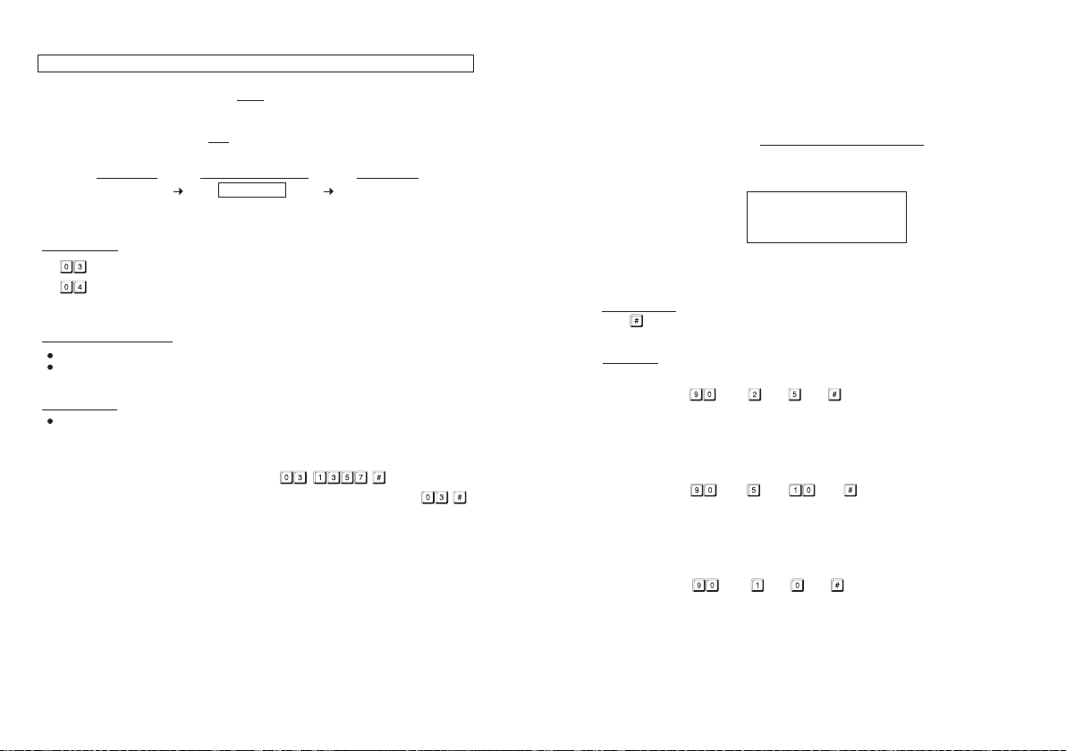
COMMON USER CODES FOR OUTPUT 1 & 2 (Locations 03 & 04)
The Common
an enhance code. The Common User Codes MUST work in the form of “Card + Common Code” to
operate the outputs to increase the security of the access control system. See Media 4 at Locations
10 & 20 for more information.
NOTE: Common User Code alone can NOT operate the Outputs directly.
(1) LOCATIONS
-- Location Stores The Common User Code for Output 1
-- Location Stores The Common User Code for Output 2
(2) COMMON USER CODES
The Common User Code can be 4 to 8 digits.
When a new Common User Code is keyed in and confirmed, the old one is replaced.
(3) VALIDATION
Pressing key to confirm code entry.
Example:
a) Set
b) Deleted a Common User Code from memory: Key in the Location number and #. ----
User Codes 1 and 2 are prepared for operating of the Output 1 and 2 respectively as
LOCATIONS COMMON USER CODE VALIDATION
-
(1) (2)
4 to
8 Digits
(3)
a Common User Code “1 3 5 7” for Output 1 ----
NOTE:
1) Momentary Contact
pressed. Output 1 activates automatically (door is released) when the delay time reaches.
2)
Holding Contact -- The user MUST
Egress Delay time until Output 1 activates. If the egress button is released before the end of the
Egress Delay, the timer will stop to count and reset.
For safety, it is necessary to put a sticker next to the egress button telling how to open the
door if “Holding Contact” is enabled.
Example: A sticker for an egress button that is programmed with “Holding Contact” of 5 seconds.
-- The Egress Delay starts to count when the egress button is momentarily
hold the egress button in contact for the whole period of the
Press & Hold The B
utton
5 Seconds Minimum
Until The Door Is Open
3) The Egress Delay does not affect the operation of the User Codes/Cards for Output 1. The User
s/Cards a
Code
(4) VALIDATION
Press key once . Two-beeps confirms the entry
EXAMPLES:
Example 1: Set Egress Button in Momentary contact of 5 seconds with delay & warning beep
(a) (b) (c) (d)
(a) Egress function programming, (b) Momentary contact with warning, (c) Delay time of 5 seconds
to release door, (d) Entry confirmation
Example 2: Set Egress Button in Holding contact of 10 seconds with warning beep
(a) (b) (c) (d)
(a) Egress function programming, (b) Holding contact mode with warning, (c) Holding time of 10
seconds to release door, (d) Entry confirmation
lways give INSTANT action.
Example 3: Set Egress Button in Momentary contact without delay (This is the default setting)
(a) (b) (c) (d)
(a) Egress function programming, (b) Momentary contact without delay, (c) Release door instantly,
(d) Entry confirmation
Page 21

EGRESS DELA
(1) LOCA
Key in Location
(2) CONFIGURATIONS OF THE EGRESS WARNING
Key in the number to enable 1 of the 6 configurations described below:
--- Momentary Contact Mode without Warning -- (Default)
Press the B
Good for silent area. The people have to wait for the door open until the delay time reaches.
--- Momentary Contact Mode with Warning Beep
Press the Button once. The system gives Warning Beeps during the Egress Delay.
Good for the place required attention. The keypad beeps during the people are waiting for the
door open.
--- Holding Contact Mode without Warning
Press a
Good for the silent area. The people require to press & hold the button until the delay time
reaches for the door open.
--- Holding Contact Mode with Warning Beep
Press a
Good for the place required attention. The keypad beeps while the button is kept pressed during
the people are waiting for the door open.
(3) EGRES
--- No Delay – (Default)
utput 1 activates instantly (the door is released instantly) when the Egress Button is pressed.
O
– --- Egress Delay Timing
a number of 1 to 99 into the box to enable the Egress Delay . The number is the time in second,
Put
which starts to count when the Egress Button is pressed. Output 1 activates (the door is released)
when the delay time reaches.
Y , WARNING AND ALARM (Location 90)
CONFIGURATIONS VALIDATIONDELAY TIMELOCATION
TION
-
(2) (4)(3)(1)
or
-
utton once. No warning or alarm is given during Egress Delay.
nd hold the Button. No warning or alarm is given during the Egress Delay.
nd hold the Button. The system gives Warning Beeps during Egress Delay.
S DELAY TIMER
USER CODES / CARDS FOR OUTPUT 1 & 2 (Locations 10 & 20)
LOCATIONS MEDIA USER ID CARD / USER CODE VALIDATION
(1) (2) (5)(4)(3)
(1) LOCATIONS (User Groups)
oup 1 – 1,000 User Codes / Cards for controlling Output 1
– Gr
– Group 2 – 100 User Codes / Cards for controlling Output 2
(2) MEDIA (Operation Media)- please also see page 12 for more information of their security level
ards Only – 125Khz Proximity EM Card
– C
– U
ser Codes Only – 4-8 Digits
ards + Secondary User Code(s) – See Note (a)
– C
– C
ards + Common User Code – See Note (b)
(3) USER ID (The IDs of The User Codes and Cards)
– – 1
(4) CARD / USER CODE
Read EM Card or key in User Code into each assigned User ID.
(5) VALIDATION
Press the key once. Two-beep confirms the entry.
NOTE:
(a) The Secondary User Code is a user code putting after a card in programming. It can be a
proprietary user code for each user card or a code repeatedly used for a group of user cards as
group user code (e.g. for a group of staff working in the same department).
(b) The Common User Codes for the Output 1 & 2 have been programmed first at Locations 03 & 04
respectively. It is not necessary to key in the code again in programming here and it will follow
the card automatically after the card is read.
(c) Deletion of an User Code or Card (if the card was lost) can be done by keying-in its ID number.
For deleting an existing cards, simply read the card once and confirm. It does not require the ID
number. The Card includes the combinations of (1) Card Only, (2) Card + Secondary User Code
and (3) Card + Common User Code.
ards / User Codes from the selected User ID – See Note (c)
– Delete C
Group Clearing. Clear all the User Codes & Cards of the selected User Group
–
ocation
. Clearing takes few seconds to a minute.
L
–
,000 User IDs for the User Codes & Cards in User Group 1 (Output 1)
– 1
00 User IDs for the User Codes & Cards in User Group 2 (Output 2)
Page 22

EXAMPLES – PROGRAMMING AND OPERATION
1) Example 1 -- EM Card Only :
i) Programming :
Read Card
(a) (b) (c
(a) The card is programmed for operating Output 1
(b) The operation is medium EM Card only
(c) Take ID number 001 in Group 1 to store the card, which is one of the IDs in 000-999
(d) Put the card close to the reader, one beep confirms the reading
(e) Press # to store the “Card”, two-beep confirms a valid entry
ii) Operation : (while the system is back to operation mode)
Read Card
(a)
(a) Read the EM card. Two-beep confirms the card is read and Output 1 activates
) (d) (e)
2) Example 2 -- Private User Code Only :
i) Programming :
High Tr
affic Passage:
A short buffer time may be necessary for opening a door outward after pressing the egress button
for those exits open to a high traffic passage. An egress button with short delay and warning beeps
helps the user to pay attention to the people passing by to prevent hitting them when the door is
pushed outward.
Emergency Exit:
Emergency Exit is not open to the public for daily use. It is for emergency case only. It is usually
closed and watched by guards. The egress button of this keypad can be programmed to offer exit
delay with warning beeps and even gives alarm output to trigger an alarm system when the door is
forced to open or the door is open after the exit delay expired. It is an useful tool to get attention of
the person on duty.
WARNING
Do not enable Egress Delay if instant door open for leaving is the main
concern in your area.
Make sure the Egress Delay does not affect the safety in your service
area before enabling the function in Location 90.
The default setting of the system is NO DELA
Y.
(a) (b) (c
(a) The Private User Code is programmed for operating Output 2
(b) The operation medium is Private User Code only
(c) Take ID number 001 in Group 2 to store the Private User Code, which is one of the IDs in
001-100
(d) Put Private User Code “1 2 3 4” into the storage location
(e) Press # to store the “Private User Code”, two-beep confirms a valid entry
ii) Operation : (while the system is back to operation mode)
(a) (b)
(a) Key in the Private User Code “1 2 3 4”
(b) Confirm it with the # key. Output 2 activates
) (d) (e)
Page 23
INTELLIGENT EGRESS BUT
INTRODUCTION
Most
of the keypads for access control are just for controlling “Going In” from outside. It is not
enough for today’s access control systems. In fact, controlling “Going Out” is also very important in
some public passage areas those are not allowed to use locks or digital keypads for stopping of
“Going Out” due to safety reasons. Such as hospitals, kindergartens, elderly homes, convenient
stores, emergency exits etc.. The wardens, teachers, shopkeepers and the guards are always
required to keep an eye on people to prevent unattended leaving, shoplifting, and unauthorized use
of the emergency exits.
The Intelligent Egress Button can be programmed to do something to get attention from the person
on duty before the door is opened. The button offers programmable egress delay, delay with
warning, holding button for the delay, momentary button contact with warning for the delay and
even gives alarm when a controlled door is opened.
Locations 90 is the place for setting the desired functions for the Egress Button.
The functions programmed to the Egress Button do not affect the normal operation of the keypad.
The operation of the keypad with Code or Card is always in the first priority to give instant action to
the output relay 1 for door strike.
It is NOT required to program the Egress Button with the special function in normal use. Just leave
it on its default values.
WHERE AND WHY “GOING OUT” NEEDS ATTENTION
Examples for some areas may need an Intelligent Egress Button:
Hospital:
Some of the patients are not allowed to leave the ward without doctor’s permission. An egress
button with exit delay and warning beeps will help the nurse or warden to get attention to the door
when the egress button is pressed. Further setting of the egress button with holding contact delay
even gives higher level of security to a controlled door.
Kindergarten:
Young children are always active. Some of them may be willing to go out to explore their ways of
playing. For safety reason, teachers have to watch all of them in the attended area. Leaving school
alone without the companion of parents or teacher is dangerous to young children. An egress button
with delay and warning beeps will be helpful to prevent the children trying to go out without getting
the attention of the teacher.
Elderly Home:
The elderly needs constant attention and care. Some old people have poor memory . They may forget
the way to come back if they leave home alone. An egress button with delay and warning beep will
easily get the attention of the warden before the door is open.
Convenient Store:
Most of the convenient stores have just only one or two shopkeepers on duty. They are usually the
cashier. Shoplifting may easily happen while the shopkeeper is busily serving customers at the
cashier desk. A holding contact egress button with delay and warning beeps may help to stop most
of the shoplifting. As the thief knows that he is gotten attention by the shopkeeper before the door
is open.
TON – AN UNIQUE FEATURE OF THE KEYPAD
Code
3) Example 3 -- EM Card + Secondary User
i) Programming :
(a) (b) (c
(a) The card is programmed for operating Output 1
(b) The operation medium is EM Card + Secondary User Code
(c) Take the ID number 002 in Group 1 to store the Card & Code, which is one of the IDs in 000-999
(d) Put the card close to the reader. One beep confirms the reading
(e) Put Secondary User Code “2 4 6 8 0” after reading of card
(f) Press # to store the “Card + Secondary User Code”, two-beep confirms a valid entry
ii) Operation : (while the system is back to operation mode)
Read Card
(a) (b) (c)
(a) Read the EM card. Two-beep confirms the reading and 30 seconds waiting time is given for
entry of the User Code, the Amber LED keeps flashing
(b) Key in the Secondary User Code “2 4 6 8 0”
(c) Confirm it with the # key. Output 1 activates
Read Card
) (d) (e) (f)
:
4) Example 4 -- EM Card + Common User Code:
i) Programming :
(a) (b) (c
(a) The card is programmed for operating Output 1
(b) The operation medium is “EM Card + Common User Code”
(c) Take ID number 003 in Group 1 to store the card, which is one of the IDs in 000-999
Read
the EM card. One beep confirms the reading. (No need to key in a Common User Code but
(d)
there MUST be a Common User Code already recorded in Location 03; (or 04 for O/P 2).
(e) Press # to store the “Card”. Two-beep confirms a valid entry
ii) Operation : (while the system is back to operation mode)
Read Card
(a) (b) (c)
(a) Read the EM card. Two-beep confirms the reading and 30 seconds waiting time is giv en for entry
of the Common User Code, the Amber LED keeps flashing
(b) Key in the Common User Code “1 3 5 7” (the number programmed in “Location 0 3” for Output
1 in the previous Example)
(c) Confirm it with the # key. Output 1 activates
Read Card
) (d) (e)
Common User Code
Page 24

5) Example 5 -- Delete An User Code & / or EM Card (for O/P 1 or 2) :
i) Delete An User Code or
(a) (b) (c) (d)
(a) Key in the User Group that the User ID belongs to. “10” for Group 1, “20” for Group 2
(b) Key in “5” that is the Command Code for making a deletion
the User ID that stored the User Code, the lost EM card or the EM Card+User Code
Key in
(c)
(d) Press the # key. Two-beep confirms a valid entry and the Code and/or Card in that User ID is
cleared
ii) Delete an EM Card
(a) (b) (c) (d)
(a) Key in the User Group that the EM Card belongs to. “1 0” for Group 1, “2 0” for Group 2
(b) Key in “5” that is the Command Code for making a deletion
(c) Read the EM card. One-beep confirms the reading. Read the Card only also makes a valid deletion
to the Card working with the Common User Code or the Secondary User Code
(d) Press the # key. Two-beep confirms a valid entry. The EM Card in that User ID is cleared. Key in
the User ID is not required.
A Lost EM Card
User ID
Read Card
6) Example 6 – Clear The Whole Group of Users :
Whole group of users inc
(a) (b) (c)
(a) The User Group 1 – “10” is selected to be cleared. “20” for Group 2
(b) Key in the Group Deletion Command, 0 9 9 9
(c) Confirm the deletion with #. All the User Codes and Cards in Group 1 are cleared. It takes few
seconds to a minute to complete depending on the data stored.
7) Example 7 – Report A
The Dur
ess Codes are Prime User Codes in the system. In the “EM Card + Secondary User Code”
or “EM Card + Common User Code” operation, they can be used to replace the “Secondary User
Code” or the “Common User Code” to operate the specific output and report a duress alarm event.
Programming is not required. The system has this function automatically while Duress Code exists.
Operation : (while the system is in the operation mode)
(a) (b) (c)
(a) Read the EM card. Two-beep confirms the reading and 30 seconds waiting time is given for
entry of the Duress Code, the Amber LED keeps flashing
(b) Key in one of the Duress Codes for the specific output (the Code programmed in “Location 41
and 42 for Output 1 and 2 respectively)
(c) Confirm it with the # key. The specific Output activ ates in a normal wa y and the Duress Output
also activates to report Duress Event to an alarm system.
NOTE: The Duress Event can not be reported if the operation mode is EM Card alone. It is required
to key in the Duress Code directly instead of EM card to report Duress Event.
luding the Codes and Cards can be cleared with the following command.
Duress While Using EM Card :
Duress CodeRead Card
DOOR FORCED OPEN WARNING & TIMING (Location 80)
FUNCTION MODES
or -
TION
(1) LOCA
Key in Location
(2) FUNCTION MODES FOR DOOR FORCED OPEN WARNING
The Door Forced Open Warning function works with a Door Position Sensing switch equipped on the
door (usually a magnetic contact). Once a Timing Figure is put into the Function Mode box, the
warning mode is enabled.
--- Door Forced Open W
-
The Timing Figure for the Warning can be 1-999 seconds. The keypad generates the door forced
open warning beeps instantly if the door is forced to open without a valid User Code/Card or pressing
of Egress Button. The beeps will last as long as the time set on the timer and it can be stopped at
anytime with an User Code/Card in Group 1 before the end of the time.
The Manner of The Door Forced Open Warning:
a) The door is forced to open (without using Code/Card or Egress Button) – Warning
b) The door is opened with Code/Card – No Warning
c) The door is opened with Egress Button – No Warning
(3) VALIDATION
Press key once . Two-beeps confirms the entry
DOOR PROPPED-UP W
(1) LOCA
Key in Location
(2) FUNCTION MODES FOR DOOR PROPPED-UP WARNING
If somebody opened the door and left it open longer than the allowable delay time, the keypad will
generate door propped-up warning until the door is re-closed. There is warning beeps from the
keypad only but it does not activate the alarm output. This function works with a door position
sensing switch equipped on the door.
--- Door Forced Open W
TION
arning OFF – (Default)
ARNING & THE DELAY TIME (Location 81)
arning & Timing
(2) (3)(1)
FUNCTION MODES
or -
(2) (3)(1)
VALIDATIONLOCATION
V
ALIDATIONLOCATION
--- Door Propped-up Warning OFF – (Default)
-
--- Door Propped-up Warning ON & The Delay T
The Delay Time can be 1 to 999 seconds. It is the allowed time for door open without starting
warning.
(3) VALIDATION
Press key once . Two-beeps confirms the entry
ime
Page 25
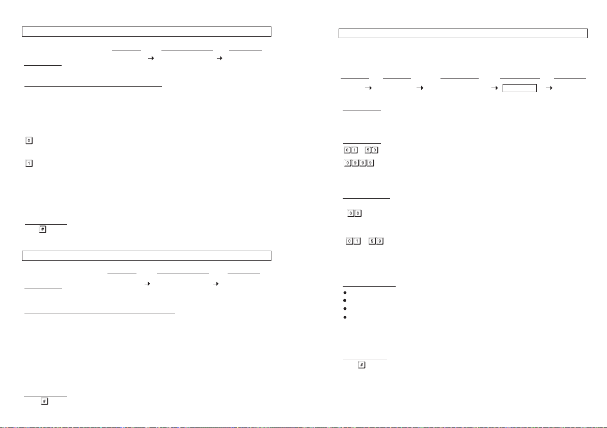
OUTPUT OPERATION ANNOUNCER (Location 72)
FUNCTION MODES
or
TION
(1) LOCA
Key in Location
(2) FUNCTION MODES FOR OUTPUT ANNOUNCER
Output announcer gives notification beep on the operation status of the outputs. There are two
notification modes available for the selection.The notification is also OFF while the Pacifier Tone OFF
mode in the Location 71 is selected.
NOTE:
In
multi-station operation, the output announcer only goes to the keypad that has been operated but
not all the keypads in the system.
--- No Notification
The output operation notification is OFF but does note affect the normal pacifier tones.
--- 1 Second Long Notification -- (Default)
1 second notification beep is given when the output relay activates. It is prepared to notify the
person outside the door when the lock is released and the door can be opened. It is good for door
lock that gives no sound when it activates, such as a magnetic lock.
--- 2 Short Beeps Notification
2 short beeps notification is given when the output relay activates.
(3) VALIDATION
Press
STA
(1) LOCA
Key in Location
(2) FUNCTION MODES FOR STANDBY FLASHING LIGHT
Some people find the flashing light of the status LED (the amber LED) is annoying during standby,
especially at the night time. The standby flashing can be ON-OFF with the setting here.
--- Standby Flashing ON -- (Default)
The Status LED gives Standby Flashing all the time. It also gives the light indications showing the
operation status of the system.
key on
ce . Two-beeps confirms the entry
TUS LED FLASHING ON-OFF DURING STANDBY (Location 73)
FUNCTION MODES
TION
(2) (3)(1)
or
(2) (3)(1)
VALIDATIONLOCATION
VALIDATIONLOCATION
--- Standby Flashing OFF
The Stan
dby Flashing is OFF but it does not affect the system status indications.
(3) VALIDATION
Press
ce . Two-beeps confirms the entry
key on
VISITOR CODES (FOR OUTPUT 1 ONL
The Visitor
Codes are temporary user codes for Output 1 (mainly for door strike in access control).
They can be programmed as “One Time Codes” or “Codes with Time Limit”. The Visitor Codes
will be cleared automatically after use if they are one time codes, or, when the allowed time
expires.
-
(1) LOCATION
Key in Location
(2) VISITOR ID
---
(3) VALID PERIOD
The codes in this box MUST be two digits and they represent the time of operation.
--- One Time Code
One Time Code has no time limit but it can only be used for ONCE. It is cleared after use.
- --- Time Limit in Hour(s)
(4) VISITOR CODES
NOTE: All V
their valid time limit.
(5) VALIDATION
Press key once. Two-beeps confirms the entry.
-
--- 50 Visitor IDs for the 50 visitor codes. They are T
Clear all the Visitor Codes in Location 40. Please see the Programming
example below for the details.
Visitor Code can be set with the valid time limit of 1 Hour to 99 Hours with a two-digit
The
number of 01 to 99. The visitor code is cleared when the time limit reaches.
The Visitor Codes can be 4-8 digits for Manual Mode code entry.
tor Codes MUST be in the same digit length with the Master Code for Auto Mode code entry.
The Visi
The Visitor Codes can not r
When a new Visitor Code is put in the same Code box, the old code is replaced.
isitor Codes will be cleared after power down to prevent extension/confusion of
eset Duress Output.
Y) (Location 40)
VISITOR CODE VALIDATIONLOCATION VISITOR ID VALID PERIOD
or -
4-8 DIGITS
wo-digit numbers
(5)(4)(3)(2)(1)
Page 26

EXAMPLES:
Example 1: Set
(a) (b) (c) (d) (e)
(a) Visitor Code Programming, (b) The Visitor ID, (c) An One Time Code, (d) The Visitor Code, (e)
Example 2: Set a “Visitor Code” with the number of “1 3 7 8” that is valid for three hours
(a) (b) (c) (d) (e)
(a) Visitor Code Programming, (b) The Visitor ID, (c) Valid for 3 Hours, (d) The Visitor Code, (e)
Example 3: Delete a “Visitor Code” from Vistor ID 02 in the memory
(a) (b) (c)
(a) Visitor Code Programming, (b) The Visitor ID, (c) Delete Confirmation
Example 4: Clear all “Visitor Codes” in Location 40
(a) (b) (c)
(a) Visitor Code Location, (b) The Deletion Command Code, (c) Confirmation, all Visitor Codes are
a “One Time Visitor Code” with the number of “1 2 6 8” for the Output 1
Entry Confirmation
onfirmation
Entry C
cleared
USER CODE ENTRY MODE – Auto or Manual (Location 70)
ENTRY MODES
TION
(1) LOCA
Key in Location
(2) USER CODE ENTRY MODES
Two modes 1 and 2 are available for User Code entry options. The EM Card is always in Auto
Entry Mode and is not affected by the selection here.
--- Auto Entry Mode
Auto E
In the Auto Entry Mode, the User Codes MUST be set in the same digit length of the Master
Code (For example, if the Master Code is 5 digits, then all User Codes must be in 5 digits as well.
All other User Codes not in 5 digits become invalid). When the number of digits reaches, the system
will check the User Code automatically. Good for high traffic access control.
--- Manual Entry Mode – (Default)
Manua
Codes can be 4-8 digits arbitrary and they are NOT required to be in the same digit length of the
Master Code. Manual Entry increases the level of security in code trial by the unauthorized people.
(3) VALIDATION
Press
PACIFIER TONES ON-OFF SELECTION (Location 71)
(1) LOCA
Key in Location
(2) FUNCTION MODES FOR PACIFIER TONES
Pacifier Tone is the Beep Tones from the keypad, which include the tones of Successful Key entry
(1 beep) and the Unsuccessful User Code/Card entry (5 beeps).
NOTE:
The beeps for the Warning and the Power-up Delay do not belong to pacifier tones and can not be
OFF.
--- Pacifier T
--- Pacifier T
(3) VALIDATION
Press key once. Two-beeps confirms the entry
ntry Mode requires no pressing of the # key after code entry for code checking.
l Entry Mode always requires the # key following the User Code for code checking. The User
key once . T
wo-beeps confirms the entry
TION
one ON – (Default)
All the Pacifier Tones available from the keypad are enabled. They are the response tones
indicating the operation status of the keypad after a Card/User Code is entered.
one OFF
All the Pacifier Tones are OFF. Good for place needs for a silent environment.
or
(2) (3)(1)
FUNCTION MODES VALIDATIONLOCATION
or
(2) (3)(1)
VALIDATIONLOCATION
Page 27
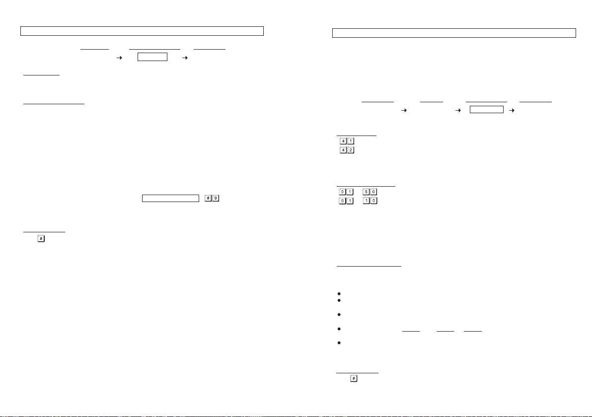
PERSONAL SAFETY AND SYSTEM LOCK
(1) LOCA
TION
Key in Location
(2) LOCK-UP OPTIONS
The Options are represented by the following Numbers. They are described below:
--- After 10 suc
--- After
cessive false Card/User Code trials, the keypad locks during 60 seconds.
aul
t)
-- (Def
10 successive false Card/User Code trials, activates the Duress output to switch to (-)
ground.The Duress Output can be released with any user Code or Card in the User Group 1
or Super User Code.
-UP (Location 60)
LOCK-UP OPTIONS
1 to 2 Digits
VALIDATIONLOCATION
(3)(2)(1)
DURESS CODES (FOR OUTPUTS 1 & 2) (Locations 41 & 42)
ess Codes are prepared for those Important Persons in case of DURESS while he is operating
Dur
the access control keypad. The duress code operates like a normal User Code for Output 1 or 2, and
at the same time activates the Duress Output without any indication. The user may use it to report
an emergency and ask for help silently when he is forced to operate the keypad if the Duress
Output is connected with a security system (for example, an Auto-dialer).
NOTE: The Duress Codes are always valid. They are not governed by any inhibit or lockup function
in the system.
LOCATIONS CODE ID
-
(1) LOCATIONS
– Duress Codes for Output 1
– Duress Codes for Output 2
-
DURESS CODE
4-8 DIGITS
VALIDATION
(4)(3)(2)(1)
- --- S
Example: Release the lock-up --
(3) VALIDATION
Press key once . Two-beeps confirms the entry
election of after 5 to 10 successive Card/User Code trials, the keypad locks during
15 minutes. The keypad can be reset to release the lock-up with the “Super User
Code” in the following way.
SUPER USER CODE
--- Disappearance of a
ll the above lock-up securities.
(2) DURESS CODE IDs
- 50 Duress Code IDs for The Output 1
- 10 Duress Code IDs for The Output 2
Please see the programming example below for the details.
(3) THE DURESS CODES
50 and 10 Duress Codes can be programmed for Output 1 and 2 respectively. They are stored in
their two-digit Code ID box. When a new Code is put into the same Code ID box, the old code is
replaced.
(4) VALIDATION
Press key once. Two-beeps confirms the entry.
= Clear all the Duress Codes from the selected Location group
The Duress Codes are 4-8 digits for Manual Mode code entry.
The Duress Codes MUST be in the same digit length with the Master Code for Auto Mode
code entry.
Always set a Duress Code that is easy to remember in Panic Situation. Only one number
different from the daily used User Code is highly recommended.
Example: User Code is 1 3 6 9, then 3 3 6 9 or 1 3 6 0 might be a good choice for the
Duress Code.
The Duress Code can also be used to replace the Secondary User Code or Common
User Code in Card reading for the Duress reporting.
.
Page 28

EXAMPLES:
Example 1: Set a
(a) (b) (c) (d)
(a) Duress Code for Output 1, (b) Duress Code ID, (c) The Duress Code, (e) Entry Confirmation
Example 2: Set
(a) (b) (c) (d)
(a) Duress Code for Output 2, (b) Duress Code ID, (c) The Duress Code, (e) Entry Confirmation
“Duress Code” with the number of “3 3 6 9” for Output 1
a “Duress Code” with the number of “2 3 9 8 0” for Output 2
Programming and Operation Examples:
(i) Set the starting and stopping time for the real-time inhibition period
et Inhibition Period from 12:30 PM (today) – 1:30 PM (same day) for lunch time:
a) S
b) Set Inhibition Period from 6:30 PM (today) – 8:15 AM (next day) for office close:
NOTE:
1) The start and stop time figures are 24 hours basis. They are 4-digit figures from the smallest
00:00 to the largest 23:59.
in the memory
Example 3: Delete an Output 1 “Duress Code” from Duress Code ID
(a
(a) Duress Code for Output 1, (b) The Duress Code ID, (c) Delete Confirmation
Example 4: Clear The Whole Group of Duress Codes from Location
(a) (b) (c
(a) Group Location , (b) The Group Deletion Command, (c) Confirmation, all Duress Codes
in Location are cleared.
OPERATION AND FUNCTION OF THE DURES
The Duress C
alarm) and at the same time activates the specific Relay Output 1, 2 or 3 just like a normal User Code.
The Duress Code always activates the Relay Output in its group, but, does not de-activate (stop) the
Duress Output. ONLY a normal User Code or Card in anyone of the user groups, or a Super User
Code can reset (de-activate) the Duress Output.
For Example:
Key in The Duress Code 3 3 6 9 of the Group 1 (for Output 1) To Command The Duress Function :
----- Duress Output activates (switches to (-) ground) & Output 1 activates.
Key in The Duress Code 3 3 6 9 in Group 1 (for Output 1) Again :
----- Duress Output keeps activating and no change in its state (keeps to (-)
Key in A Normal User Code to Reset Duress (For Example: 1369 is An User Code for Output 1):
----- Duress Output resets (back to OFF state) but does not activate Output 1.
) (b) (c)
)
S CODE
ode(s) has double actions when it is keyed in. It activates the Duress Output (for duress
ground) & O
utput 1 activates again.
:
2) Entry of the two figure values from Small (Start) to Large (Stop) for the period ofinhibition; the
inhibition will start and stop in the same day. See example (a).
3) Entry of the two figure values from Large (Start) to Small (Stop) for the period of inhibition; the
inhibition will start at the time of the day; thus stop in the next day. See example (b).
4) The keypad does not accept the “Start” and “Stop” times with same value. The two time figures
must be different.
(ii) Clear the function of inhibition
Clear the time settings to stop the function of inhibition:
(iii) Pause the real-time inhibition manually
Th
e real-time inhibition can be stopped temporarily if require; such as the staff work overtime in
office. The inhibition can be paused manually with Super User Code before or during the
inhibition period. The pause is toggle and does not affect the real time period counting.
Super User Code
---- Inhibition paused [Inhibit LED(Red) Flashing]
Super User Code
---- Inhibition resumes [Inhibit LED(Red) ON]
NOTE:
The “INHIBIT” LED(Red) is flashing during the paused period; and it is ON after inhibition resumes.
(iv) Open door lock with Super User Code at anytime
The Super User code is valid all the time even in the inhibition period. This function does not
affect the real time period counting.
---- The door is open
Super User Code
Page 29

START & STOP TIMES FOR DAILY INHIBITION OF OUTPUT 1 (Location 56)
Set
ting with start and stop times into the keypad, the real-time inhibition period for output 1 will
recycle daily until the time settings are cleared.
This function works with the real-time-clock. Set up the real-time at Location 55 is necessary.
For safety reason, the Egress Button is designed always valid. The door lock (controlled by output
1) can be opened with it at anytime during inhibition.
START TIME VALIDATIONLOCATION
(1)
(1) LOCATION
Key in Location
(2) START TIME
– Set the real-time inhibition starting time in Hour and Minute. The allowed time
The starting time is based on 24 hours daily with the first two digits for hours and the last two digits
for minutes. The time in second always starts at 0 0.
(3) STOP TIME
– Set the real-time inhibition stopping time in Hour and Minute. The allowed time
The stopping time is based on 24 hours daily with the first two digits for hours and the last two digits
for minutes. The time in second always starts at 0 0.
(4) VALIDATION
Press key once.
Two-beep confirms the setting.
HOURS MINUTES
(2)
figure is 00:00 – 23:59
figure is 00:00 – 23:59
STOP TIME
HOURS MINUTES
(3)
(4)
Report Duress in EM Card Operation
The Du
ress Codes are Prime User Codes in the system. In the “EM Card + Secondary User Code”
or “EM Card + Common User Code” operation, they can be used to replace the “Secondary User
Code” or the “Common User Code” to operate the specific output and report a duress alarm event.
Programming is not required. The system has the function automatically while Duress Code exists.
Operation : Taking Duress Code 3 3 6 9 in Group 1 for Output 1 As Example
Read Card
(a) (b) (c)
a) Read the EM card. Two-beeps confirm the reading and 30 seconds waiting time is given for the
entry of Duress Code, the Amber LED keeps flashing
b) Key in the Duress Codes 3 3 6 9 for operating Output 1
c) Confirm it with the key. Output 1 activates in a normal way and the Duress Output also
activates to report Duress Event to an alarm system if connected.
NOTE: Duress Event can not be reported with EM Card alone. User can only directly use Duress
Code to open the door a
nd report duress event in emergency
Page 30
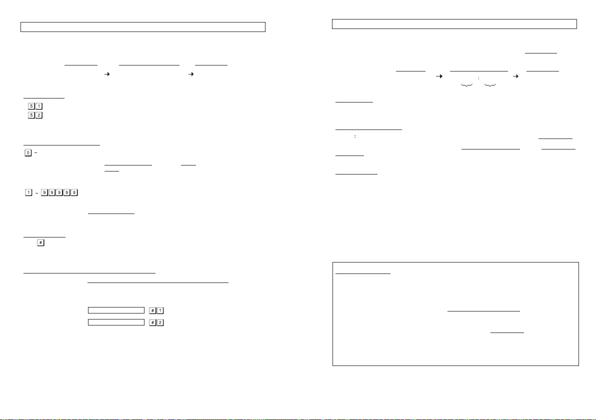
OUTPUT MODE & TIMING FOR OUTPUT 1 and 2 (Locations 51 & 52)
The t
wo relay outputs are programmable for Start/Stop or Timing modes. Apart from door access
control, alarm arm-disarm control, they are also universal timers for automatic operators in
industry with their 99,999 seconds (over 24 hours) programmable timer.
OUTPUT MODE & TIME VALIDATIONLOCATIONS
-
(1) LOCATIONS
-- Location for Output 1
-- Location for Output 2
(2) OUTPUT MODE & TIMING
Start /Stop Mode (Toggle)
The
number 0 sets the output to Start / Stop mode. The output Starts when an User Code and/or
Card is entered/read; the output Stops when an User Code and/or Card is entered/read again.
-- Seconds Momentary --- (Default -- Momentary 5 Seconds)
The output can be set in Momentary Mode with the time of 1 second to 99,999 seconds. The
output will reset automatically when the time expires.
(3) VALIDATION
Press key once. Two-beeps confirms the entry.
or -
(3)(2)(1)
SYSTEM REAL-TIME-CLOCK (Location 55)
This 24 hour
inhibition to relay output 1 (mainly for electric door lock strike).
No real-time-clock setting is required if daily start-stop inhibition at Location 56 is not
enabled.
(1) LOCATION
Key in Location
(2) CURRENT REAL TIME
– The current time in Hour and Minute. The allowed time figure is 00:00 – 23:59
The time setting is based on 24 hours daily with the first two digits for hours and the last two digits
for minutes. The time in second always starts at 0 0.
(3) VALIDATION
Press key once.
Two-beep confirms the setting and the clock starts to count in 24 hour basis from the pr ogrammed
current time.
Programming Examples:
a) Set the current time of “10:30” (AM) to the keypad ----
b) Set the current time of “6:45” (PM) to the keypad ------
real-time-clock provides the daily time base for starting and stopping the function of
CURRENT REAL TIME VALIDATIONLOCATION
(1)
HOURS MIN
UTES
(2)
(3)
RESET OUTPUT TIMER WITH SUPER USER CODE
The Output Timer can be RESET manually at anytime with the Super User Code that operates
the desired output before the end of the time.
Example:
Reset Output 1 Timer -- ------------- Output 1 stops
Reset Output 2 Timer -- ------------- Output 2 stops
SUPER USER CODE
SUPER USER CODE
IMPORTANT NOTE:
eal-time-clock stops after power failure, which makes the real-time inhibition loses
1) The r
its time base. It is necessary to re-program the system’s real-time-clock unless the
keypad is back up with UPS.
2) The keypad gives warning beeps of 3 fast beeps / 5 seconds continuously after
power failure until the real-time-clock is re-programmed.
3) No “after power failure warning beep” will be given if Location 56 is not programmed
with Start/Stop times.
4) Suggest to program the clock every 3-6 months to keep time accuracy; or when time
deviation is found.
Page 31

ST
FCC
1. This device complies with Part 15 of the FCC Rules. Operation is subject to the following two
conditions:
(1) This device may not cause harmful interference, and
(2) This device must accept any interference received, including interference that may cause
undesired operation.
2. Changes or modifications not expressly approved by the party responsible for compliance could
void the user’s authority to operate the equipment.
This equipment has been tested and found to comply with the limits for a Class B digital device,
pursuant to part 15 of the FCC Rules. These limits are designed to provide reasonable protection
against harmful interference in a residential installation. This equipment generates, uses and can
radiate radio frequency energy and, if not installed and used in accordance with the instructions,
may cause harmful interference to radio communications. However, there is no guarantee that
interference will not occur in a particular installation. If this equipment does cause harmful
interference to radio or television reception, which can be determined by turning the equipment off
and on, the user is encouraged to try to correct the interference by one or more of the following
measures:
—Reorient or relocate the receiving antenna.
—Increase the separation between the equipment and receiver.
—Connect the equipment into an outlet on a circuit different from that to which the receiver is
connected.
—Consult the dealer or an experienced radio/ TV tec hn i cia n for help.
ATEMENT
 Loading...