

Page 1
1 This device complies with Part 15 of the FCC Rules
Operation is subject to the following two conditions:
(1)This device may not cause harmful interference, and
(2)This device must accept any interference received, including interference
that may cause undesired operation.
2. Changes or modifications not expressly approved by the party responsible for
compliance could void the user's authority to operate the equipment.
FCC STATEMENT
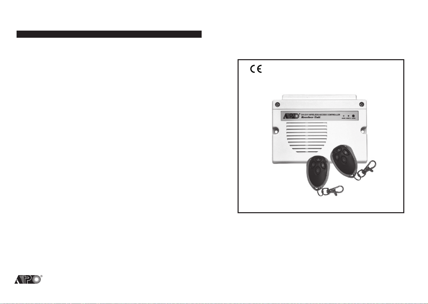
WIRELESS ACCESS CONTROLLER
RoHS
Compliance
AEI PROTECT-ON SYSTEMS LIMITED
www.apo-hk.com
DA-2311
Operating Instructions
FOR ELECTRIC LOCK AND SECURITY SYSTEM
VERSION: 12/2011
Page 2
TABLE OF CONTENTS
. . . . . . . . . . . . . . . . . . . . . . . . . . . . . . . . . . . . . . . . . . . . . . . . . . . . . . . . . . . . . . . . . . . . . . . . . . . . . . . .
INTRODUCTION
FEATURES & SPECIFICATIONS
ACKAGE CONTENTS
P
THE RECEIVER UNIT --- (Figure 1)
THE MAIN CIRCUIT BOARD --- (Figure 2)
INSTALLATION
Precautions
Connection Terminals
Remote Controlled Keyfobs & Wireless Keypad
APPLICATION EXAMPLES
A Wireless Access Control Door Lock System
Directly Use An Open Collector Output for Alarm Arm-Disarm Control
DA-2311 is
keyfobs and/or the optional DK-2310 wireless keypad to build up a wireless access control system.
The four controlling channels control the master output relay, the two open collector auxiliary outputs
and the built-in door chime. The controller can also work independently with the two supplied remote
control keyfobs (DA-12) and the optional egress button and door bell button wired to their connect
terminals.
. . .
. . . . . . . . . . . . . . . . . . . . . . . . . . . . . . . . . . . . . . . . . . . . . . . . . . . . . . . . . . . . . . . . . . . . 3
. . . . . . . . . . . . . . . . . . . . . . . . . . . . . . . . . . . . . . . . . . . . . . . . . . . . . . . . . . . . . . . . . . . . . . . . . . . . .
. . . . . . . . . . . . . . . . . . . . . . . . . . . . . . . . . . . . . . . . . . . . . . . . . . . . . . . . . . . . . . . . .
. . . . . . . . . . . . . . . . . . . . . . . . . . . . . . . . . . . . . . . . . . . . . . . . . . . . . . . . . .
. . . . . . . . . . . . . . . . . . . . . . . . . . . . . . . . . . . . . . . . . . . . . . . . . . . . . . . . . . . . . . . . . . . . . . . . . . . . . . . . . . . . 5
. . . . . . . . . . . . . . . . . . . . . . . . . . . . . . . . . . . . . . . . . . . . . . . . . . . . . . . . . . . . . . . . . . . . . . . . . . . . . . . . . . . . .
. . . . . . . . . . . . . . . . . . . . . . . . . . . . . . . . . . . . . . . . . . . . . . . . . . . . . . . . . . . . . . . . . . . . . . . . . .
. . . . . . . . . . . . . . . . . . . . . . . . . . . . . . . . . . . . . . . . . . . . . . . . . . . .
. . . . . . . . . . . . . . . . . . . . . . . . . . . . . . . . . . . . . . . . . . . . . . . . . . . . . . . . . . . . . . . . . . . . . . . .
. . . . . . . . . . . . . . . . . . . . . . . . . . . . . . . . . . . . . . . . . . . . . . . . . . . . . . . 7
. . . . . . . . . . . . . . . . . . . . . . . . . . . . . . . . . 7
5 - 6
INTRODUCTION
a 4-channel access control receiver designed to work in conjunction with its remote control
2
The Controller of The Receiver :
Operating Voltage: 12V
3
4
4
Operating Current: 60mA (quiescent) to 90mA (Output relay active)
Operating Temperature: -20 C to +70 C
Environmental Humidity: 5-95% Relative Humidity Non-condensing
FEATURES & SPECIFICATIONS
-24V DC, Auto Adjusting
Timing for Output Relay (Output 1): 1-60 Seconds Adjustable Timer (For Door Lock)
5
6
7
Timing for Output 2 & 3 : 2 Seconds Momentary Approximately (For Auxiliary Controls)
Door Lock Compatibility : Fail-safe or Fail-secure Electric Lock
Input Sensing Terminals:
a) Egress – For Connection of Normally Open (N.O.) Egress Button(s)
b) Door Bell – For Connection of Normally Open (N.O.) Bell Button(s)
Output Control Terminals:
a) Output 1 – N.C. & N.O. Relay Dry Contacts, 5A/24VDC Maximum Rating
b) Output 2 – Transistor Open Collector, 24VDC/100mA Sink Maximum
c) Output 3 – Transistor Open Collector, 24VDC/100mA Sink Maximum
Compatibility: DK-2310 Wireless Keypad, DA-12 Remote Control Keyfob
Dimensions: 32.5(H) X 120(W) X 87(D)mm Plastic Box
Weight: 250g net
The Remote Keyfob + Receiver :
Number of ID Codes for The Keyfobs : Over 1 Million
Number of Wireless Keypads & Keyfobs Accommodated by The Receiver :
40 Maximum
4 Control Channels : Output 1, 2, 3 & Door Chime
Operation Frequency : 433MHz
Control Distance : 50 Meters Approx. in Open Space
Receiver Type : Super-heterodyne
Operation Voltage of The Keyfob (DA-12) : 12V Alkaline Battery, Type 27A (not included)
Weight : 32g
Specications are subject to change for modication without notice
PACKAGE CONTENTS
• One Access Control Receiver (DA-2311)
Two Remote Control Keyfobs (DA-12)
•
• One Pack of Mounting Screws
• One Owner’s Manual
2
3
Page 3
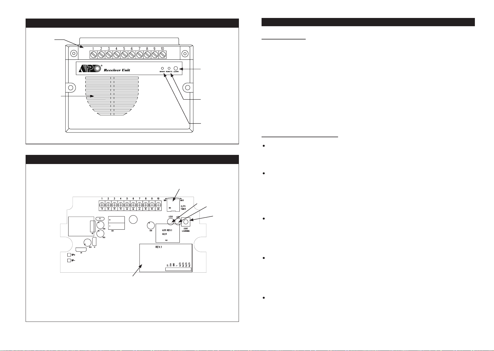
THE RECEIVER UNIT --- (Figure 1)
INSTALLATION
CONNECTION
TERMINALS
INTERNAL
DOOR CHIME
DA-2311 WIRELESS ACCESS CONTROLLER
THE MAIN CIRCUIT BOARD --- (Figure 2)
ADJUSTABLE TIMER FOR OUTPUT 1
TURN CLOCKWISE FOR MAXIMUM TIME
CODE
LEARNING
BUTTON
REMOTE
CONTROL
SIGNAL
STATUS
MAINS
MAINS
REMOTE
LEARN
&
l) PRECAUTIONS
1) Installation Location:
The receiver is
from the wireless keypad or the remote control keyfob(s), a correct installation location is important.
i) Install it on a location inside the house facing to the open space and there has no strong electro magnetic wave signals near it.
ii) Do not install it in a concrete room or under a concrete stair, which shortens the control distance.
2) Prevent Accidental Short Circuit:
In the previous experience, most of the damages caused in the installation are accidental touching
of the components on circuit board with the wires carrying power. Please be patient in the
installation. Study the manual to become familiar with the system beforehand is also important.
i) Do not apply power to the system while it is in installation.
ii) Check carefully all the wirings are correct before applying power to the system for testing.
ll) CONNECTION TERMINALS
1 - 2 : 12-24V DC -- ( Power Input Terminal )
nnect to a 12-24V DC power supply. Terminal 1 is the (+) power input point. The (-) supply
Co
Terminal 2 is the common grounding point of the system. The system accepts full input voltage
range.
3 - 4 - 5 : OUTPUT 1 -- ( Output Relay )
5 Amp relay dry contact controlled by Channel 1 of the wireless keypad or the remote keyfob(s). It
is for door strike. Terminal 3 is Normally Closed contact (N.C.), terminal 5 is Normally Open contact
(N.O.) and terminal 4 is the common point of the two contacts. Use N.C. output for Fail-safe locking
device; and N.O. output for Fail-secure locking device.
The operation timing is controlled by the Adjustable Timer (1-60 seconds), which is located on the
main circuit board inside the box. See Figure 2.
6 : OUTPUT 2 -- ( An Open Collector Output )
A two seconds momentary open collector output controlled by Channel 2 of the wireless keypad
or the remote keyfob(s) for auxiliary control. Such as arm-disarm control of an alarm system or
actuation of an electronic automatic operator. It is equivalent to a Normally Open contact (N.O.)
switching to (-) ground. The maximum rating of this output is 24V/100mA sink, which is sufcient to
drive a small device, such as a relay.
working at the frequency of 433.92Mhz. To get the best receiving result of the signals
RECEIVER FOR
REMOTE CONTROL
NOTE: Factory suggests that the timer adjustment should be done by the Installer only.
4
7 : OUTPUT 3 -- ( An Open Collector Output )
A two seconds momentary open collector output controlled by Channel 3 of the wireless keypad
or the remote keyfob(s) for auxiliary control. Such as arm-disarm control of an alarm system or
actuation of an electronic automatic operator. It is equivalent to a Normally Open contact (N.O.)
switching to (-) ground. The maximum rating of this output is 24V/100mA sink, which is sufcient to
drive a small device, such as a relay.
8 : EG IN -- ( Egress Input )
A Normally Open (N.O.) input terminal referring to (-) ground. With the help of a normally open
button to activate Output 1 for door open in the same manner of using the wireless keypad or
keyfob.
Egress button is usually installed inside the house near the door for exit convenience. More than
one egress buttons can be connected in parallel to the terminal. Leave the terminal open if not used.
5
Page 4
9 : (-) GND -- ( Common Ground of The System )
A grounding point that is common to terminal 2.
10 : DOOR BELL
A terminal prepared for the connection of a Normally Open (N.O.) external bell button referring to
(-) ground to activate the built-in door chime in the same manner of using the bell button on the
wireless keypad or keyfob. More than one door bell buttons can be connected in parallel to the
terminal. Leave the terminal open if not used.
lll) REMOTE CONTROLLED KEYFOBS & WIRELESS KEYPAD
The DA-2311 receiver comes with two remote control keyfobs and is also compatible with the wireless
keypad DK-2310.
The ID codes of them are required to be learned by the receiver prior to use for controlling the Output 1,
2, 3 and the built-in door chime.
(A) Procedures of Recording The ID of A Keyfob or A Wireless Keypad -- (Learning)
_______________________________________________________________________
The keyfobs and the keypads that prepare to work with the receiver are required to be registered rst.
The receiver learns the ID of them one by one with the following procedures:
1)
Press and
ON. (The button is inside the hole. Use a pin or the tip of a ball pen to reach it)
2)
The receiver is now in Waiting Mode for 10 seconds waiting for the signal from the Keyfob or the
keypad after the Remote LED turning ON.
3)
Press any button of the Keyfob or the Bell Sign Button of the keypad ONCE within the 10 seconds
for the receiver to learn the ID Code transmitting from it.
4)
The REMOTE LED on the receiver unit turns OFF after the ID Code is learned.
5)
Take the above learning procedures 1-4 for other Keyfobs or Keypads
(B) Procedures of Deleting The ID of A Keyfob or A Wireless Keypad from Memory -- (Clearing)
_________________________________________________________________________________
If a keyfob or keypad is lost it is necessary to delete it from the memory of the receiver to make it
invalid. Every time the system will clear all the ID Codes in the deletion. Re-learning of the existing
keyfobs and keypads are necessary.
1)
Press and
the REMOTE LED gives 2 ashes to conrm that all the IDs are erased. Then the LED turns OFF.
2)
Record the ID Code of the existing Keyfobs and Keypads (not lost) into the memory again one
by one with the procedures stated in the procedures A “Recording The ID of A Keyfob or A
Wireless Keypad”
-- ( Door Bell Button Input )
Total 40 keyfobs and/or wireless keypads can be accommodated by the receiver.
hold the LEARN button on the receiver unit for 1 second until the REMOTE LED turns
hold the LEARN button on the receiver unit for 8 seconds (Remote LED turns ON) until
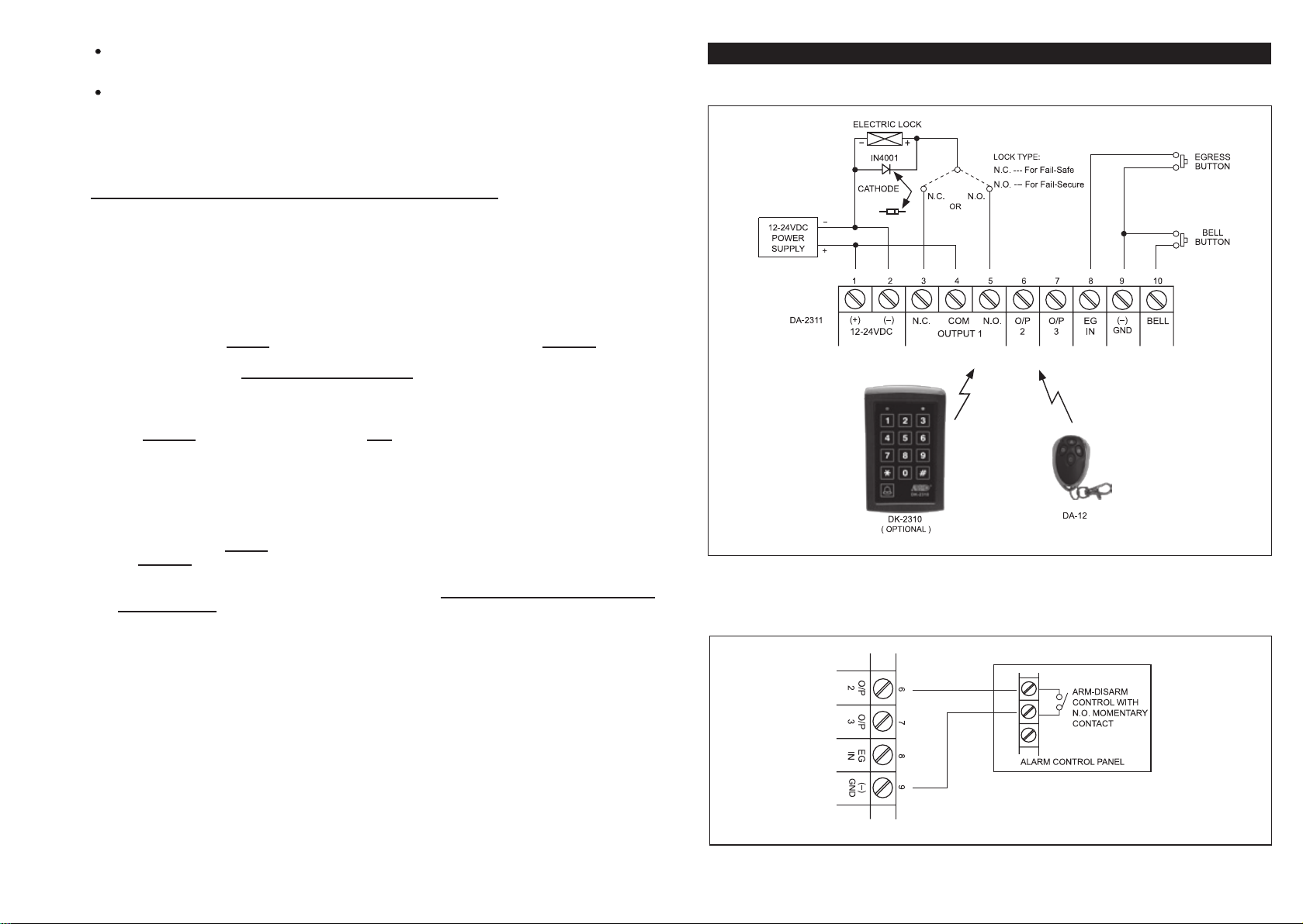
APPLICATION EXAMPLES
A Wireless Access Control Door Lock System
1)
__________________________________________
2) Directly Use An Open Collector Output for Alarm Arm-Disarm Control
______________________________________________________________
(C) Operating The System with Keyfob or Wireless Keypad -- (Operation)
______________________________________________________________
The system can be operated with the supplied Keyfobs or the optional Keypads.
Operate with Keyfob:
1) Press button A to operate Output 1
2) Press button B to operate Output 2
3) Press button C to operate Output 3
4) Press button D to operate the built-in Door Chime
Operate with Wireless Keypad:
1) Key in one of the User Codes of Group 1 to operate Output 1
2) Key in one of the User Codes of Group 2 to operate Output 2
3) Key in one of the User Codes of Group 3 to operate Output 3
4) Press the Bell Sign button to operate the built-in Door Chime
6
7
 Loading...