

Page 1
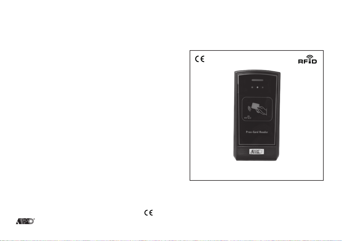
Proximity EM Card Reader
AEI PROTECT-ON SYSTEMS LIMITED
www.apo-hk.com
User Manual
VERSION: 10/2013
Page 2

TABLE OF CONTENTS
...................................................................................................................... 3
INTRODUCTION
................................................................................................................... 3
SPECIFICATIONS
................................................................................................................ 3
Package Contents
................................................................................................................ 4
THE FRONT PANEL
........................................................................................................... 4
Power Indicator (Blue)
Status Indicators
Card Reader Window
....................................................................................................................... 5
INSTALLATION
Installation Location
Precautions for Accidental Short Circuit
THE CONNECTION TERMINALS
(A)CONNECTION TERMINAL 1-6 FOR AR-2802S (STANDARD VERSION)
1 – 2 : 12-24V DC (Power Input Terminals)
3 : Data I/O Bus
.............................................................................................................. 6
4 – 5 : Tamper Switch
6 : LED Control Input Port
(B)ADDITIONAL CONNECTION TERMINAL 7-10 FOR AR-2802A (ADVANCED VERSION)
7 : Buzzer Control Input Port
8 : D0 Wiegand Data Output Port
.............................................................................................. 7
9 : D1 Wiegand Data Output Port
10 : RS-232 (TX) Output Port
EXTERMAL CONNECTION OF WIEGAND AND RS-232
WIEGAND OUTPUT FORMATS (AR-2802A ONLY)
The Timing and Electrical Manner of The Wiegand Data Output
Wiegand Data 26-Bit, 34-Bit or 37-Bit Selection Jumper
1) 26-Bit Wiegand Data Output
2) 34-Bit Wiegand Data Output
3) 37-Bit Wiegand Data Output
The 26 Bit Wiegand Data Output From The EM Cards
RS-232 OUTPUT FORMAT (AR-2802A ONLY)
OPERATION
APPLICATION EXAMPLES
.......................................................................... 12
1) Works As Auxiliary Reader for The AR-2808
2) Works As Auxiliary Reader for The DK-2800 Series Keypads (2nd Generation or Above)
......in Stand Alone Mode
3) Works As Auxiliary Reader for The DK-2800 Series Server Keypads
......in Split-decoded Mode
..................................................................................................................... 4
............................................................................................................. 4
................................................................................................................ 5
...................................................................................................................... 6
......................................................................................................... 6
......... 6
..................................................................................................... 6
........................................................................................................................... 11
.................................................................................................... 12
............................................................................................................ 13
.......................................................................................................... 14
................................................................................... 5
.......................................................................................... 6
................................................................................. 6
................................ 6
.............................................................................................. 7
................................................................................................... 7
.............................................................................................. 8
.............................................................................................. 8
.............................................................................................. 8
...................................................... 7
................................................................ 8
.................................................. 8
.............................................................. 8
................................................................. 9
.................................................................... 10
2
Page 3
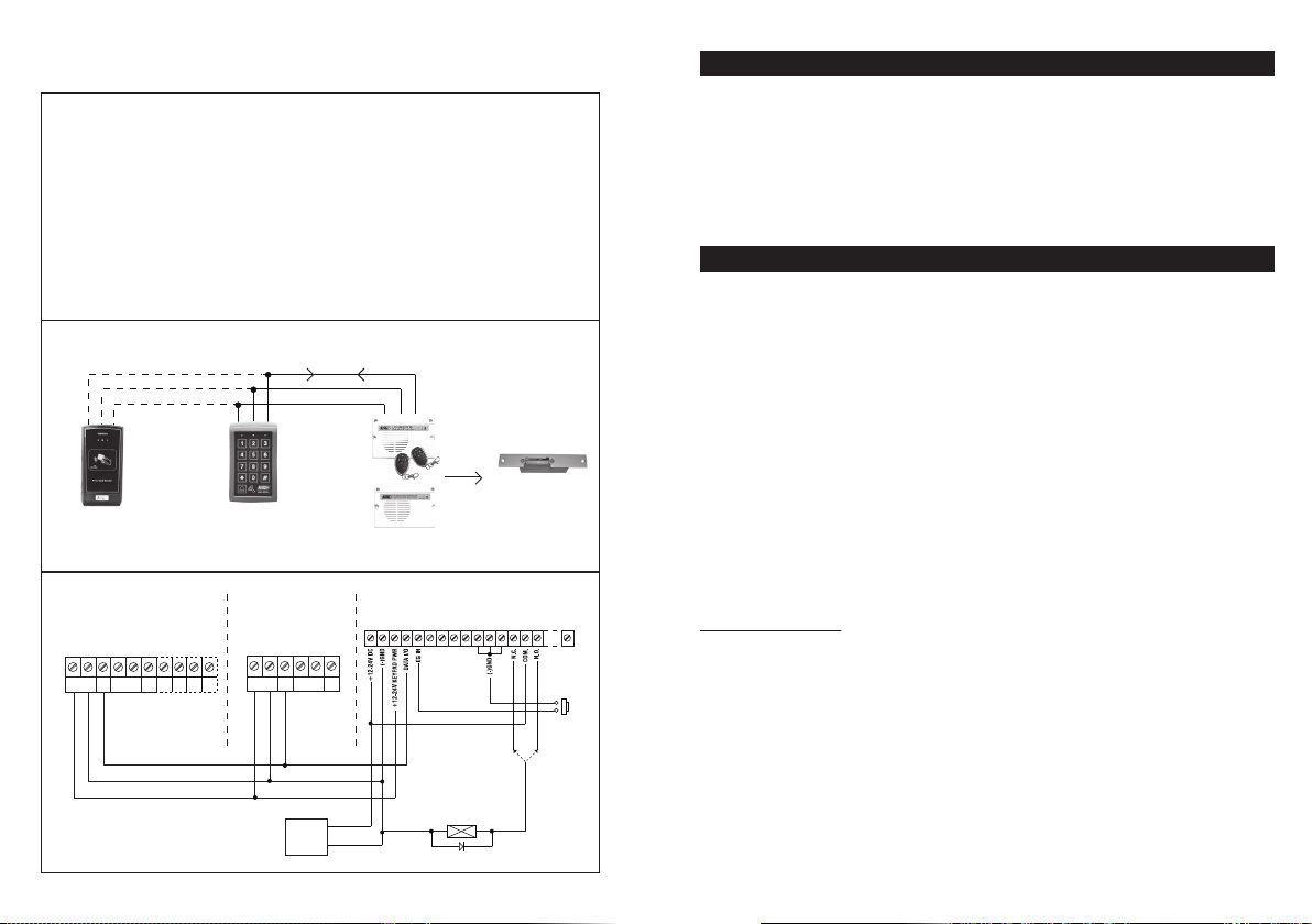
3) Auxiliary Reader for DK-2800 Split-Decoded Keypads (2nd Generation)
Description
The auxiliary readers are also companion of the split-decoded keypads. Maximum 3 auxiliary
readers can be connected in parallel with the Data I/O Bus of the DK-2800 server keypad for
multi-station operation (compatible with all the server keypads in DK-2800 2nd generation
family). The auxiliary readers work in the same manner like the server keypad in card reading.
A split-decoded keypad consists of one server keypad unit (DK-2866S/A, DK-2872S/A or
DK-2890S) and one decoder unit (DA-2800 or DA-2801) in package. Split-decoded keypad
provides high overall security with the decoder unit installing inside the house for all the input
and output connections while the keypad unit is installed outside. The communications among
the devices connecting with the Data I/O Bus are digital data managed by the server keypad.
Sabotage on the outside keypad and reader can not make door open.
System Connection
DATA I/O BUS
COMMON( - ) GND
( + ) POWER SUPPLY
DA-2800
DA-2801
DA-2800 OR DA-2801
SPLITE-DECODER
*OUTPUT RELAY
N.C. FOR Fail-Safe Lock
N.O. FOR Fail-Secure Lock
ELECTRIC
LOCK
( + )
( – )
1N4004
ELECTRIC
LOCK
*
OR
N.C. N.O.
EGRESS
BUTTON
AR-2802
AUXILIARY READER
Wiring Diagram
AR-2802 AUXILIARY READER
DATA
TAMPER
( + ) ( – )
I/O
N.C.
12-24V DC
DATA I/O BUS
LED
D0
BUZ
( – )
( + )
OR
DK-2866S
DK-2872S
DK-2890S
THE SERVER
DK-2866S (Example)
10987654321
RS
D1
232
THE SERVER
DK-2866R (Example)
DATA
TAMPER
( + ) ( – )
I/O
N.C.
12-24V DC
12-24V DC
POWER
SUPPLY
14
654321
LED
( + )
( – )
OR
Split-Decoder
INTRODUCTION
AR-2802 is a proximity EM card reader. It is compatible with all the DK-2800 series keypads (2nd
generation or above) and the access control reader AR-2808 in utilizing the self-contained Data I/O
bus to set up a multi-station access control system. The advanced version also provides Wiegand
data and RS-232 output for custom project development that works with access controller and / or
computer.
● AR-2802S – Standard Version, Consists Data I/O Port
● AR-2802A – Advanced Version, Consists Data I/O Port, Wiegand Data & RS-232 Outputs
SPECIFICATIONS
● Operation Voltage: 12-24V DC Auto-adjust
● Operating Current: 80mA Maximum
● Operation Temperature: -20℃ to +70℃
● Environmental Humidity: 5-95% Relative Humidity, Non-condensing
● Working Environment & Ingress Protection: Indoor or Outdoor, IP-55 Weatherproof
● Compatible User Cards: Standard 125Khz Proximity EM Cards and Keyfobs
● Data Communication Ports:
.a) Data I/O Port – Compatible with the APO Keypads & Readers
.b) Wiegand Output Port – 26-bit, 34-bit or 37-bit Standard Format, Selectable (Version A Only)
.c) RS232 Output Port – Output Format at 9600bps (Version A Only)
● Tamper Switch: N.C. Dry Contact, 50mA/24VDC Maximum
● Dimensions: 60(W) X 120(H) X 25(D) mm
● Weight: 100g Net
● Housing: ABS Plastic
Specifications are subject to change for modification without notice
23151413121110987654321
N.O.
PACKAGE CONTENTS
● One AR-2802 Reader (S or A Version)
● Two EM Cards
● One Pack of Mounting Screws
● One User Manual
3
Page 4
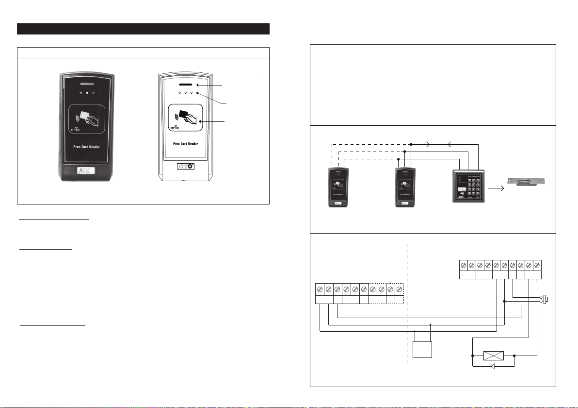
THE FRONT PANEL
AR2802 FRONT PANEL
Power Indicator
Status Indicators
(Red, Amber, Green)
Card Reader Window
●
Power Indicator (Blue)
It is ON after the reader is powered.
●
Status Indicators
Red – A normally OFF indicator, it is ON in system lock-up due to false trials or manual inhibition
It is flashing during the master keypad in inhibition pause period.
Amber – It is ON in standby and turns OFF momentary when a valid card is read.
Green – An indicator controlled by external controller. It is prepared for free connection, e.g. such
as a Wiegand feedback indicator.
It turns ON momentary when a valid card is read.
●
Card Reader Window
A place gives best result for reading the EM cards.
2) Auxiliary Reader for DK-2800 Keypads (2nd Generation)
Description
Maximum 3 auxiliary readers AR-2802 can be connected in parallel with the Data I/O Bus of the
DK-2800 master keypad for multi-station operation (compatible with all the keypads in DK-2800
2nd generation family). The auxiliary readers work in the same manner like the master keypad
in card reading. The master keypad is the server of the system in this example. It manages the
data among the devices connected to the Data I/O Bus.
The auxiliary reader is even compatible with master keypads without reader (such as the
DK-2831, DK-2851 and DK-2881 etc.). The auxiliary reader acts as EM card reader of the
master keypad and the user cards can be programmed to the master keypad through it.
System Connection
AR-2802
AUXILIARY
READER
Wiring Diagram
AR-2802 AUXILIARY READER
DATA
TAMPER
( + ) ( – )
I/O
12-24V DC
N.C.
DATA I/O BUS
COMMON( – ) GND
( + ) POWER SUPPLY
LED D1
BUZ
D0
AR-2802
AUXILIARY
READER
10987654321
RS
232
DATA I/O BUS
( – )
( + )
( + )
12VDC
POWER
SUPPLY
OR
Any Keypad
of DK-2800
Series
( – )
DK-2871 (Example)
MASTER READER
(THE SERVER)
DK-2871(Example)
MESTER KEYPAD - THE SERVER
TAMPER
DOOR BELL
N.C.
N.O.
( + ) ( – )
ELECTRIC
LOCK
( + ) ( – )
12VDC
ELECTRIC
LOCK
DOOR LOCK
DATA
( + ) ( – )
I/OEGIN
10987654321
EGRESS
BUTTON
N.O.
N.O.
1N4004
4
13
*JUMPER SELECTION
FOR ELECTRIC LOCK OF
(1) FAIL-SAFE OR
(2) FAIL-SECURE
Page 5
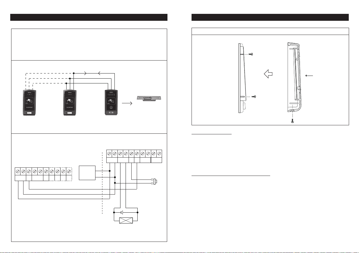
APPLICATION EXAMPLES
1) Auxiliary Reader for AR-2808
Description
Maximum 3 auxiliary readers AR-2802 can be connected in parallel with the Data I/O Bus of
the AR2808 access control reader for multi-station operation. The auxiliary reader(s) works in
the same manner like the master reader in card reading. The master reader is the server of the
system in this example. It manages the data among the devices connected to the Data I/O
Bus.
System Connection
DATA I/O BUS
COMMON( – ) GND
( +) POWER SUPPLY
ELECTRIC
LOCK
AR-2802
AUXILIARY
READER
AR-2802
AUXILIARY
READER
AR-2808
THE SERVER
Wiring Diagram
AR-2808 MASTER READER (THE SERVER)
TAMPER
1N4004
LOCK
DOOR BELL
DATA
N.O.
I/OEGIN
EGRESS
BUTTON
*JUMPER SELECTION
FOR ELECTRIC LOCK OF
(1) FAIL-SAFE OR
(2) FAIL-SECURE
N.O.
AR-2802 AUXILIARY READER
DATA
TAMPER
( + ) ( – )
I/O
12-24V DC
N.C.
BUZLED D1D0
10987654321
RS
232
DATA I/O BUS
( – )
( + )
12VDC
POWER
SUPPLY
( + )
( – )
12
( + ) ( – )
( + ) ( – )
DOOR LOCK
12VDC
( + ) ( – )
ELECTRIC
INSTALLATION
AR-2802 ASSEMBLY
BACK COVER
(Fix it on wall)
FRONT COVER
Installation Location
The EM Card works at the frequency of 125Khz. Installation precautions are necessary:
10987654321
N.C.
i) Make sure the location has no strong low frequency electro-magnetic wave signals near it.
---Especially in the range of 100-200Khz.
ii) If more than one keypads/readers operating in the same frequency are installed closely, make
---sure that they are at least 60cm (2ft) apart from each other to reduce interference. Otherwise, the
---reading range may be reduced.
Precautions for Accidental Short Circuit
In the previous experience, most of the damages caused during installation are accidental touch of
the components on the circuit board with the wire(s) carrying power. Always be patient and the
following precautions are necessary:
i) Study the manual thoroughly to become familiar with the system before the installation.
ii) Do Not apply power to any connection terminal of the reader during the installation.
iii) Check all the wirings carefully and confirm that they are correct before applying power to the
----reader for testing.
5
Page 6
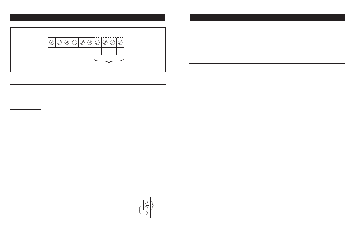
THE CONNECTION TERMINALS
10987654321
( + ) ( – )
12-24V DC
DATA
TAMPER
I/O
N.C.
WIEGAND
D0 D1
RS
232
LED
BUZ
AR-2802A ONLY
(A) TERMINALS 1-6 FOR AR-2802S (STANDARD VERSION)
1 – 2 : 12-24V DC (Power Input Terminals)
Connect the (+) to a 12-24V DC power supply or in parallel with the power supply of the master
keypad / reader. The (-) is the common grounding point of the system.
3 : Data I/O Bus
This is a data input-output bus compatible with the Data I/O bus of the DK-2800 keypads (the 2nd
generation or above) and the AR-2808 access control reader. Connect the Data I/O buses of the
reader(s) and keypad(s) in parallel.
4 – 5 : Tamper Switch
A Normally Closed (N.C.) dry contact while the reader is securely fixed on its back cover. The
contact is open while the reader is separated from the back cover. Connect this N.C. terminal to the
24 hour protection zone of an alarm system to make alarm in sabotage if required.
6 : LED Control Input Port
The Amber indicator is 0V (-) active by connecting the input terminal to (-) ground. It provides visual
feedback indication from the wiegand controller or the striking electric lock. It is for free connection.
(B) TERMINAL 7-10 FOR AR-2802A (ADVANCED VERSION)
7 : Buzzer Control Input Port
The internal Wiegand buzzer is 0V (-) active by connecting the input terminal to (-) ground. It
provides audible feedback indication from wiegand controller. Connect it to the output port of the
controller.
Remark:
Self-generated Feedback Tone ON-OFF Jumper:
The self-generated feedback tone of the reader may confuse
with the beeps feeding back from the controller in using
Wiegand data. The self-generated beeps can be selected for
ON-OFF with the jumper.
2. OFF
1. ON
F/B TONE
OPERATION
The auxiliary reader provides the output data faithfully from reading of an EM card. It uploads the
acquired data to the Data I/O bus to set up a communication path with the master keypad or reader.
The master keypad or reader interprets the data and executes the required function(s) accordingly.
The advanced version (version “A”) auxiliary reader also gives Wiegand and RS-232 data
simultaneously at separated output ports while it sends signal to the Data I/O bus.
Working with Master Keypad Via Data I/O Bus
● Read the EM card. The card’s ID will be sent to the master keypad or reader for verification.
● A valid user card (a registered card in the master) will be accepted. Two beeps confirm
....successful. The Green indicator turns ON and the Red indicator turns OFF for one second.
● An Invalid card (a card not registered in the master) will be rejected and five beeps indicate
....unsuccessful.
Working with Equipment via Wiegand and RS-232 Data (AR-2802A Only)
There is no audible feedback indication from the master keypad or reader if the reader only works
with an access controller using Wiegand and/or RS-232 data. Leave the Data I/O port open if it is
not used.
● Read the EM card. The card’s ID in Wiegand and RS-232 data format will be sent to the access
...controller and the PC respectively.
● The Wiegand and RS-232 data outputs are not affected by the card that is valid or invalid in the
...master’s registration. The reader sends the data out instantly if it is not a faulty card.
● The reader always gives 2 beeps to confirm a card is read. The Green indicator turns ON and the
...Red indicator turns OFF for one second during the data transmission.
● The on-board Wiegand LED and Buzzer are prepared for connecting with the access controller to
...get the visible and audible feedback indications. See terminals 6 & 7 for the connection details.
FCC STATEMENT
1. This device complies with Part 15 of the FCC Rules. Operation is subject to the following two
conditions:
(1) This device may not cause harmful interference.
(2) This device must accept any interference received, including interference that may cause
undesired operation.
2. Changes or modifications not expressly approved by the party responsible for compliance could
void the user's authority to operate the equipment.
6
11
Page 7
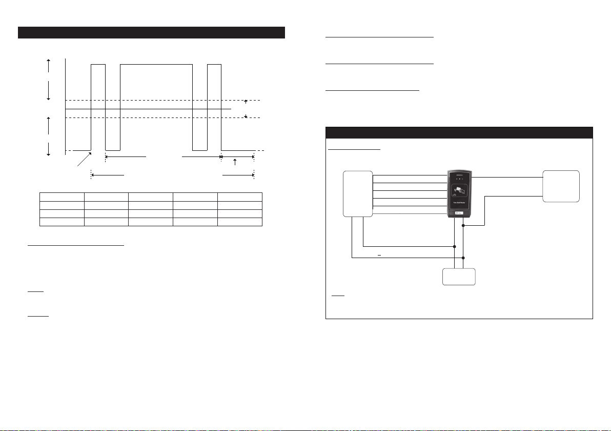
Space(=0)
Mark(=1)
RS-232 OUTPUT FORMAT
+15V
+3V
0V
-3V
-15V
Start Bit
Format
26 Bit
34 Bit
37 Bit
Start
START(0X02H)
START(0X02H)
START(0X02H)
(AR-2802A ONLY)
End
END(0x03H)
END(0x03H)
END(0x03H)
MSBLSB
0010 1000 0
8 Data Bits
Data packet corresponding to ASCII character ‘A’
Data
DATA(1-8 Char)
DATA(1-10 Char)
DATA(1-11 Char)
Indeterminate
2 Stop Bits
LRC
LRC
LRC
LRC
Region
8 : D0 Wiegand Data Output Port
This output port provides the D0 Wiegand data. Connect it to the D0 input port of the controller.
9 : D1 Wiegand Data Output Port
This output port provides the D1 Wiegand data. Connect it to the D1 input port of the controller.
10 : RS-232 (TX) Output Port
This is a standard RS-232 transmission output port. Connect it to the COM port of the PC.
See following diagram for the details.
EXTERNAL CONNECTION OF WIEGAND AND RS-232
Wiring Diagram
AR-2802A
RS-232(TX) (10)
RS-232(GND) (2)
PC
Controller
Tamper Output(COM) (4)
Tamper Output(NC) (5)
LED Control In (6)
Buzzer Control In (7)
Wiegand Data 0 Out (8)
Wiegand Data 1 Out (9)
● Check the following settings:
.....Baud Rate: 9600bps
.....Data Bit: 8
.....Parity Bit: None
.....Stop Bit: 1
LRC:
●
.....This is the result of XOR operation of each byte from Start to End.
●
NOTE:
The Maximum DATA length change from 8 to 11 characters according to the Wiegand Data
....Jumper selection.
10 7
+ (1)
(2)
Note:
RS-232 Connection — Connect to the COM port of the PC. ( Connect pin 2 of the DB-9 connector to the
terminal (10); connect the terminal (2) GND of the device to pin 5 of the DB-9 connector.)
12-24V DC GND
POWER
SUPPLY
Page 8
WIEGAND OUTPUT FORMATS (AR-2802A ONLY)
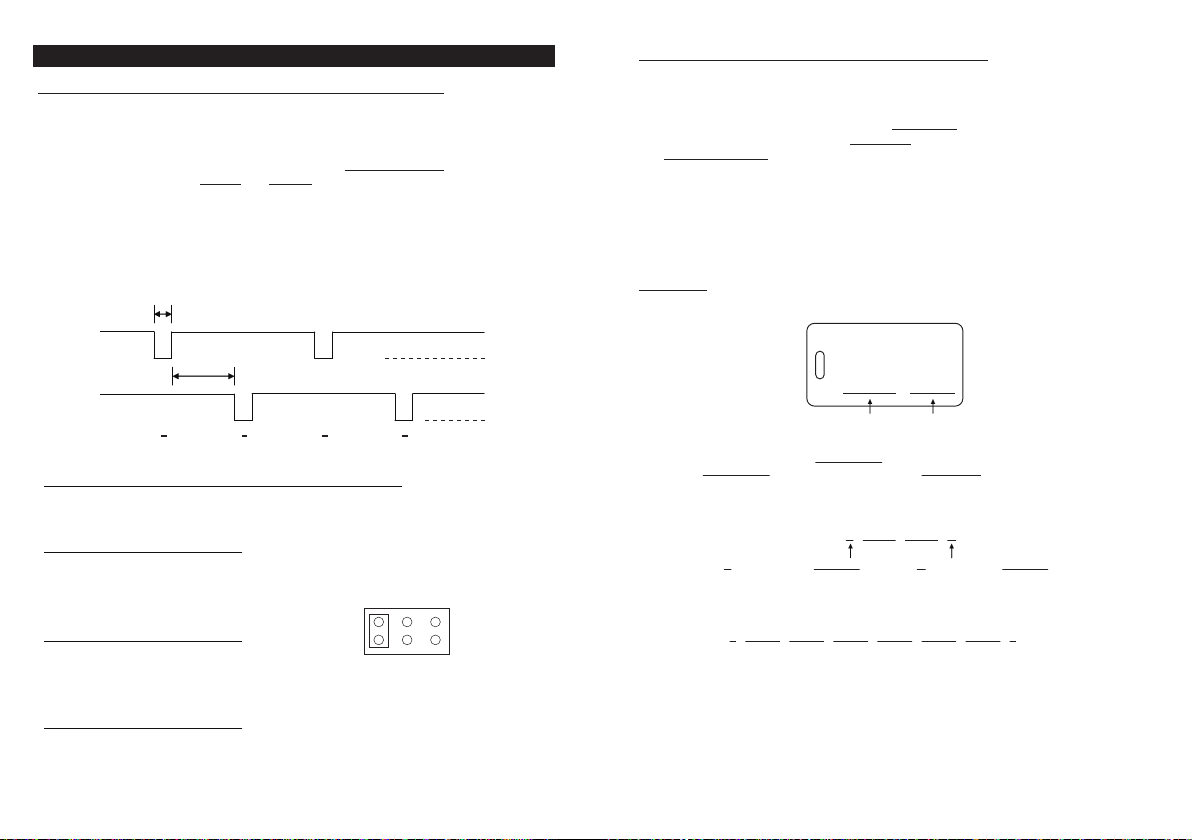
The Timing and Electrical Manner of The Wiegand Data Output
Wiegand is a common medium in the communication between readers and controller in access
control. The Wiegand data from the keypad unit provides a level of compatibility for readers and
controller that can be used by consultants in custom project development.
The Wiegand interface uses three wires, one of which is a Common Ground and two of which are
data transmission wires called DATA 0 and DATA 1. When no data is being sent both DATA 0 and
DATA 1 are at high voltage. When a “0” is sent the DATA 0 is at low voltage while the DATA 1 stays
at a high voltage. When a “1” is sent DATA 1 is at the low voltage while DATA 0 stays at the high
voltage.
The high voltage level in the keypad unit is +5VDC to accommodate for long cable runs
(approximate 500 feet) from it to the associated controller typically located in a secure closet.
Data 0 Line
Data 1 Line
50 uS pulse
2 mS pulse interval
0 1 0 1
+5V
0V
+5V
0V
Wiegand Data 26-Bit, 34-Bit or 37-Bit Selection Jumper
The Wiegand data output can be selected to 26-bit, 34-bit or 37-bit standard format with the
jumper.
1) 26-Bit Wiegand Data Output
Bit 1 : Even Parity Bit (bit 2 – bit 13)
Bit 2 – Bit 25 : 24 Bit ID Number
Bit 26 : Odd Parity Bit (bit 14 – bit 25)
31 2
2) 34-Bit Wiegand Data Output
Bit 1 : Even Parity Bit (bit 2 – bit 17)
Bit 2 – Bit 33 : 32 Bit ID Number
Bit 34 : Odd Parity Bit (bit 18 – bit 33)
WIEGAND DATA
3726 34
3) 37-Bit Wiegand Data Output
Bit 1 : Even Parity Bit (bit 2 – bit 19)
Bit 2 – Bit 36 : 35 Bit ID Number
Bit 37 : Odd Parity Bit (bit 19 – bit 36)
The 26 Bit Wiegand Data Output From The EM Cards
26-bit EM Card is the most popular one on the market. Almost all the controllers can use the 26-bit
standard format.
A 26 bit Wiegand protocol for card reading has 1 first parity bit, 24 bits of the Card ID, and 1 stop
bit for a total of 26 bits. The first parity bit is an Even parity bit calculated from the first 12 bits of
the code and the trailing parity bit is an Odd parity bit from the last 12 bits. The data transmitted
is in Hex Binary codes.
Each EM card or Keyfob is marked with an unique ID in Decimal Digits that is the code read by the
reader. The EM Card is also marked with a “3 digit + 5 digit” code that are the site code and ID
number arrangement of the Wiegand data.
EXAMPLE:
a) The Code Marked on One of The EM Cards:
0006613779
The ID Code to be read for Wiegand Output The Code does not belong to this system
The Code in Decimal Number : 6 6 1 3 7 7 9
The Code 6 6 1 3 7 7 9 Equivalent to Hex Number : 6 4 E B 1 3
b) Each Hex Number Consists of 4 Bits, Total 26 Bits of Wiegand Data Output from Card Reading:
E 6 4 E B 1 3 O
An Even Parity Bit of 6 4 E = 0 An Odd Parity Bit of B 1 3 = 1
c) The 26 bits Wiegand Data Sending Out in Hex Binary from Reading The Card:
0 0 1 1 0 0 1 0 0 1 1 1 0 1 0 1 1 0 0 0 1 0 0 1 1 1
d) The Arrangement of The Site Code and ID Number of A 26-bit EM Card:
● Site Code: Bit 2 ~ 9 (000~255)
● ID Number: Bit 10 ~ 25 (00000 ~ 65,535)
100,60179
008,18789
The Site Code and the ID number
98
 Loading...