

AEI Protect On Systems DA2800, DA2801, DK2800 User Manual
FCC STATEMENT
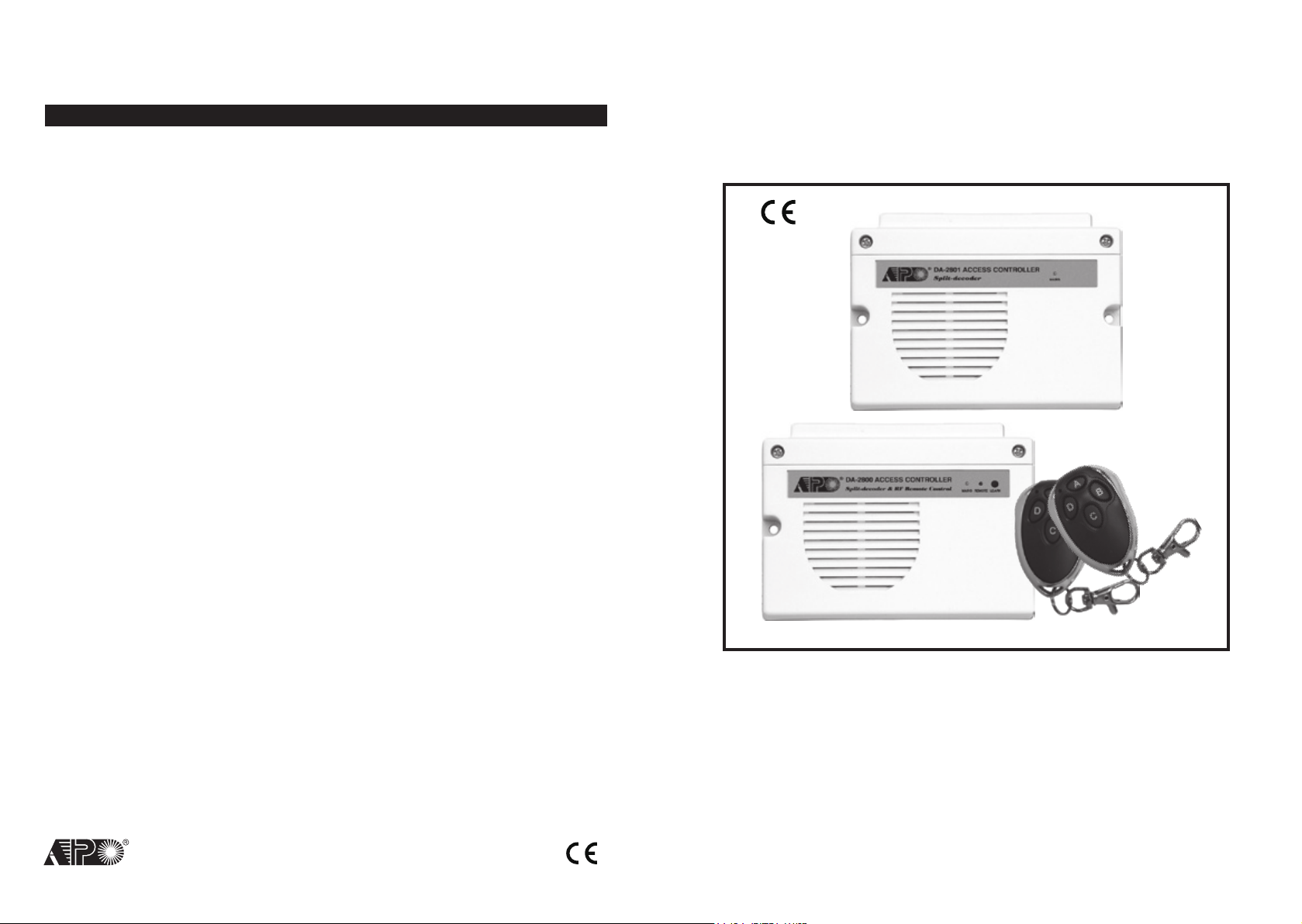
SPLIT-DECODED CONTROLLER
1. This device complies with Part 15 of the FCC Rules.
Operation is subject to the following two conditions:
(1)This device may not cause harmful interference, and
(2)This device must accept any interference received, including interference
that may cause undesired operation.
2. Changes or modifications not expressly approved by the party responsible for
compliance could void the user's authority to operate the equipment.
FOR DK-2800 SECURITY KEYP
RoHS
Compliance
ADS
AEI PROTECT-ON
www.apo-hk.com
SYSTEMS LIMITED
VERSION: 10/2010
DA
-2800 & DA-2801
Installation & Operation Manual
FOR ELECTRIC LOCK
AND SECURITY SYSTEM INSTALLATIONS
, INTER-LOCK

TABLE OF CONTENTS
INTRODUCTION
FEATURES
SPECIFICATIONS
PACKAGE CONTENTS
THE SPLIT-DECODED CONTROLLER UNIT (Figure 1)
THE MAIN CIRCUIT BOARD OF THE CONTROLLER --- (Figure 2)
INSTALLATION
Precautions
Split-Decoded Mode -- (For DA-2800 & DA-2801)
The Necessary Connections For Split-Decoded
The Function Mode Jumper Setting For Split-Decoded -- (DA-2800 Only)
The Link-Up Jumper & Link-Up Code Acquisition
The Function Mode Jumper -- (Available On DA-2800 Only)
CONNECTION TERMINALS
The Audible & Visible Signals
The Alarm Outputs & Warnings
RF Remote Controller -- (DA-2800 Only)
Stand Alone Mode -- (DA-2800 Only)
APPLICATION EXAMPLES
Basic Wirings of A Split-Decoded Door Lock
Basic Wirings of An Inter-Lock System Using Two Split-Decoded Keypads
APPLICATION HINTS FOR THE AUXILIARY TERMINALS
PROGRAMMING FOR FULL FEATURES --- (Supplementary Information)
Set System in Programming Mode with The Master Code
Direct Access to Programming Mode with The “DAP” Code – 8 0 8 0
Refresh The System with The “Refreshing Code” --- 9 9 9 9
The Default Values of The Keypad
FEATURE PROGRAMMING -- KEY IN AND STORE THE DESIRED VALUES
Programming Criteria for Codes
Record A Master Code
Record A Super User PIN
Operation And Functions of The Super User PIN
Record The Common User PINs for Output 1, 2 & 3
Record-Delete PINs or Cards for Output 1, 2, & 3
Examples – Programming And Operation
Visitor Codes (For Output 1 Only)
Duress Codes (For Outputs 1, 2 & 3)
The Operation And Function of The Duress Code
Configuration of The Output Modes for Output 1, 2 And 3
Personal Safety And System Lock-Out
. . . . . . . . . . . . . . . . . . . . . . . . . . . . . . . . . . . . . . . . . . . . . . . . . . . . . . . . . . . . . . . . . . . . . . . . . . . . . . . . . . . . . . . . . .
. . . . . . . . . . . . . . . . . . . . . . . . . . . . . . . . . . . . . . . . . . . . . . . . . . . . . . . . . . . . . . . . . . . . . . . . . . . . . . . . . . . . . . . . . . . . . .
. . . . . . . . . . . . . . . . . . . . . . . . . . . . . . . . . . . . . . . . . . . . . . . . . . . . . . . . . . . . . . . . . . . . . . . . . . . . . . . . . . . . . . . . . .
. . . . . . . . . . . . . . . . . . . . . . . . . . . . . . . . . . . . . . . . . . . . . . . . . . . . . . . . . . . . . . . . . . . . . . . . . . . . . . . . . . . . .
. . . . . . . . . . . . . . . . . . . . . . . . . . . . . . . . . . . . . . . . . . . . . . . . . . . . . . . . . . . .
. . . . . . . . . . . . . . . . . . . . . . . . . . . . . . . . . . . . . . . . . . . . . . . . . 6
. . . . . . . . . . . . . . . . . . . . . . . . . . . . . . . . . . . . . . . . . . . . . . . . . . . . . . . . . . . . . . . . . . . . . . . . . . . . . . . . . . . . . . . . . . . .
. . . . . . . . . . . . . . . . . . . . . . . . . . . . . . . . . . . . . . . . . . . . . . . . . . . . . . . . . . . . . . . . . . . . . . . . . . . . . . . . . . . . . . . . . . . .
. . . . . . . . . . . . . . . . . . . . . . . . . . . . . . . . . . . . . . . . . . . . . . . . . . . . . . . . . . . . .
. . . . . . . . . . . . . . . . . . . . . . . . . . . . . . . . . . . . . . . . . . . . . . . . . . . . . . . . . . . . . . .
. . . . . . . . . . . . . . . . . . . . . . . . . . . . . . . . . . . . . . . . . . . . . . . . . . . . . . . . . . . . . 8
. . . . . . . . . . . . . . . . . . . . . . . . . . . . . . . . . . . . . . . . . . . . . . . . . . . . 9
. . . . . . . . . . . . . . . . . . . . . . . . . . . . . . . . . . . . . . . . . . . . . . . . . . . . . . . . . . . . . . . . . . . . . . . . . . . . . . . . .
. . . . . . . . . . . . . . . . . . . . . . . . . . . . . . . . . . . . . . . . . . . . . . . . . . . . . . . . . . . . . . . . . . . . . . . . . . . .
. . . . . . . . . . . . . . . . . . . . . . . . . . . . . . . . . . . . . . . . . . . . . . . . . . . . . . . . . . . . . . . . . . . . . . . . . .
. . . . . . . . . . . . . . . . . . . . . . . . . . . . . . . . . . . . . . . . . . . . . . . . . . . . . . . . . . . . . . . . . . .
. . . . . . . . . . . . . . . . . . . . . . . . . . . . . . . . . . . . . . . . . . . . . . . . . . . . . . . . . . . . . . . . . . . . .
. . . . . . . . . . . . . . . . . . . . . . . . . . . . . . . . . . . . . . . . . . . . . . . . . . . . . . . . . . . . . . . . . . . . . . . . . . . . . . . . .
. . . . . . . . . . . . . . . . . . . . . . . . . . . . . . . . . . . . . . . . . . . . . . . . . . . . . . . . . . . . . . . .
. . . . . . . . . . . . . . . . . . . . . . . . . . . . . . . . . . . . . . . . . . . . . . . . . . . . . . .
. . . . . . . . . . . . . . . . . . . . . . . . . . . . . . . . . . . . . . . . . . . . . . . . . . . .
. . . . . . . . . . . . . . . . . . . . . . . . . . . . . . . . . . . . . . . . . . . . . . . . . .
. . . . . . . . . . . . . . . . . . . . . . . . . . . . . . . . . . . . . . . . . . . . . . . . . . . . . . . . . . . . . . . . . . . . . . .
. . . . . . . . . . . . . . . . . . . . . . . . . . . . . . . . . . . . . . . . . . . . . . . . . . . . . . . . . . . . . . . . . . . . . . . . . .
. . . . . . . . . . . . . . . . . . . . . . . . . . . . . . . . . . . . . . . . . . . . . . . . . . . . . . . . . . . . . . . . . . . . . . . . . . . . . . . . . .
. . . . . . . . . . . . . . . . . . . . . . . . . . . . . . . . . . . . . . . . . . . . . . . . . . . . . . . . . . . . . . . . . . . . . . . . . . . . . . .
. . . . . . . . . . . . . . . . . . . . . . . . . . . . . . . . . . . . . . . . . . . . . . . . . . . . . . . . . . . . .
. . . . . . . . . . . . . . . . . . . . . . . . . . . . . . . . . . . . . . . . . . . . . . . . . . . . . . . . .
. . . . . . . . . . . . . . . . . . . . . . . . . . . . . . . . . . . . . . . . . . . . . . . . . . . . . . . . . . . .
. . . . . . . . . . . . . . . . . . . . . . . . . . . . . . . . . . . . . . . . . . . . . . . . . . . . . . . . . . . . . . .
. . . . . . . . . . . . . . . . . . . . . . . . . . . . . . . . . . . . . . . . . . . . . . . . . . . . . . . . . . . . . . . . . . . . . . . .
. . . . . . . . . . . . . . . . . . . . . . . . . . . . . . . . . . . . . . . . . . . . . . . . . . . . . . . . . . . . . . . . . . . .
. . . . . . . . . . . . . . . . . . . . . . . . . . . . . . . . . . . . . . . . . . . . . . . . . . . . . . . . .
. . . . . . . . . . . . . . . . . . . . . . . . . . . . . . . . . . . . . . . . . . . . . . . . . . . .
. . . . . . . . . . . . . . . . . . . . . . . . . . . . . . . . . . . . . . . . . . . . . . . . . . . . . . . . . . . . . . . . . . .
2
. . . . . . . . . . . . . . . . . . . . . . . . . . . . . . . . . . . . . . . . . 8
. . . . . . . . . . . . . . . . . . . . . . . . . . . . . . . . . . . . . . .
. . . . . . . . . . . . . . . . . . . . . . . . . . . . . . . . . . . . . . . . .
. . . . . . . . . . . . . . . . . . . . . . . . . . . . . . . . . . . . . . . . . . .
. . . . . . . . . . . . . . . . . . . . . . . . . . . . . . . . . . . . . . . .
1 0
1 4
1 4
1 5
1 5
1 6
1 6
1 7
1 8
2 1
2 1
2 2
2 3
2 3
2 4
2 4
2 5
2 5
2 6
2 6
2 7
2 8
3 0
3 1
3 2
3 3
3 3
Door Forced Open Warning
8 0
4
4
5
5
6
7
7
7
8
& Time
Propped-up Warning & Time
8 1
Egress Delay Warning &
9 0
Alarm
Do or Openi ng Alarm &
9 1
TIMER
Operation Mode & Wiegand
9 4
Output
FUNCTION MODE / TIME:
0---OFF
1-999 Seconds
-
CODE 1
1---Momentary, No warning
2---Momentary, with warning
3---Momentary, with warning +
Alarm
4---Hold Contact, No warning
5---Hold Contact, with warning
6---Hold Contact, with warning
+ Alarm
CODE 2
0---No Delay
1-99 Seconds
ALARM TIME:
0---No Alarm
1-999 Seconds
MODES OF WIEGAND OUTPUT
0---Stand Alone Keypad
Codes & Cards Only
1---Reader
2---Master Keypad
& Cards only
3---Slave Keypad
& Cards only
FUNCTION MODE:
-
DELAY TIME:
-
All Codes & Cards
-
Valid Codes
-
Valid Codes
-
Valid
80
81
90
91
94
FUNCTION / TIME
FUNCTION / TIME
CODE 1 CODE 2
ALARM TIME
WIEGAND O/P MODE
#
#
#
#
#
Mode = 0,
Door Forced
Open
Warning OFF
Mode = 0,
Propped-up
Warning OFF
Mode = 1
Momentary,
No warning
TIME = 0
No Delay
Time = 0,
No Alarm
Mode = 0
Keypad Mode
SYSTEM CODES FUNCTION CODE ENTRY RESULTS
Fa ct or y Set Master Co de
fo r Use r to set s ystem i n
0 0 0 0
9 9 9 9
8 0 8 0
0 9 9 9
* *
progr ammin g Mode at t he
first time.
THIS IS NOT A PERMANENT
S YSTE M CO DE & I T IS
CHANGED IF A NEW MASTER
CODE IS PROGRAMMED.
REF RESH CODE -- Refresh
th e system and set all i ts
fun ct io n bac k to de fa ul t
values.
DAP C ODE-- Direct access
to programming mode. Valid
onl y in the power-up delay
period
USER PINs / Codes / Cards
whole group clearance Code
-
Key in the Code to clear all
the users in the Location
LOCATIONS:
10--- User Group 1
20--- User Group 2
30--- User Group 3
40--- Vistor Group
41--- Duress Group 1
42--- Duress Group 2
43--- Duress Group 3
Exit Programming Code
0000 * *
OR
NEW MASTER CODE
* *
9999 #
8080 #
LOCATION NO.
0999 #
**
System in Programming Mode
All programmed data are cleared and
back to the default values except the
Master Code
System in Programming Mode
Whole group of users in the selected
location are cleared
The system back to normal opration
after programming
41
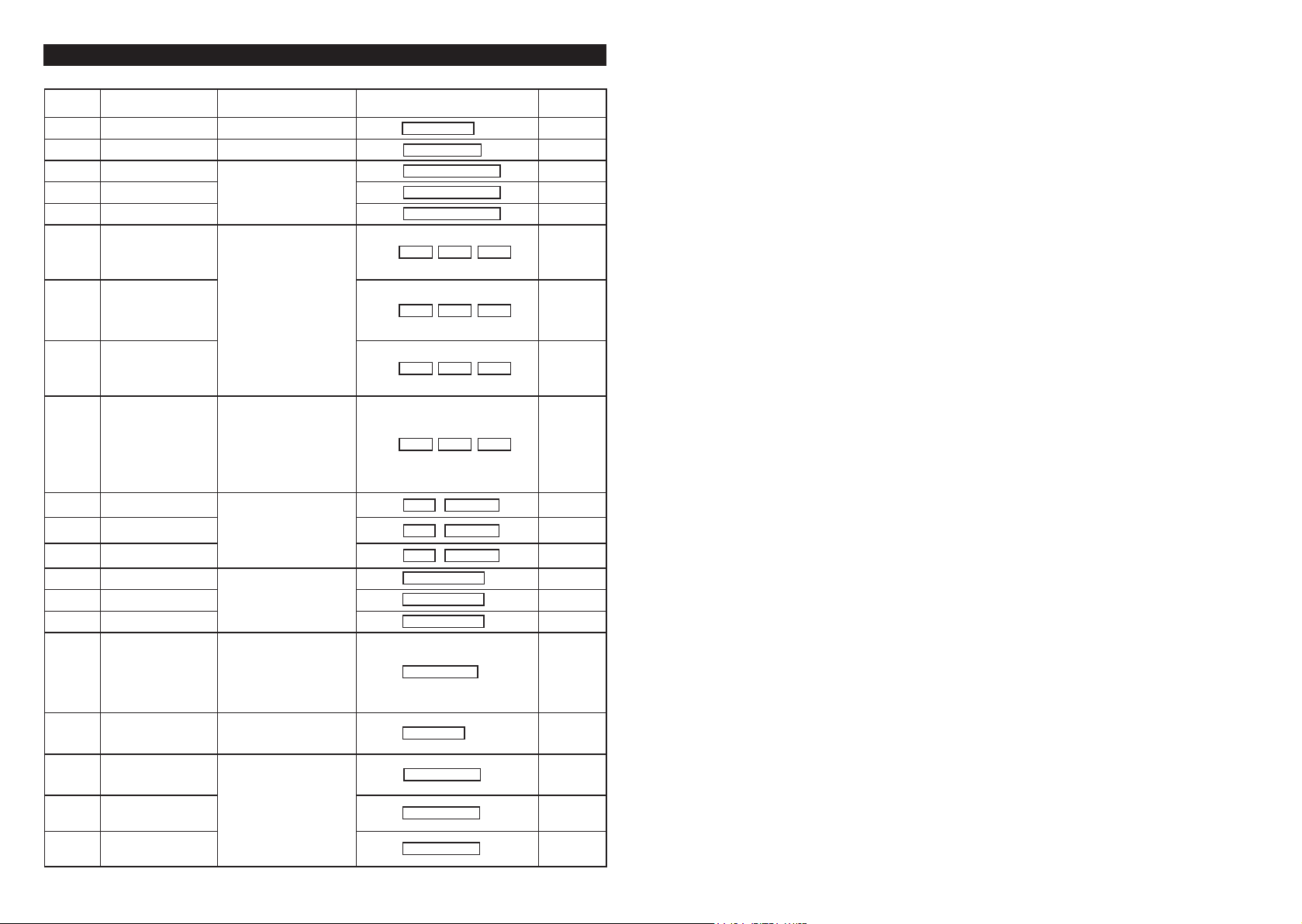
THE PROGRAMMING SUMMARY CHART --- (Supplementary Information)
LOCATION
0 1
0 2
0 3
0 4
0 5
1 0
2 0
3 0
4 0
4 1
4 2
4 3
5 1
5 2
5 3
6 0
7 0
7 1
7 2
7 3
FUNCTION
Master Code 4-8 Digits
Super User PIN 4-8 Digits
Common User PIN for O/P 1
Common User PIN for O/P 2
Common User PIN for O/P 3
User PINs / Cards for O/P 1
User PINs / Cards for O/P 2
User PINs / Cards for O/P 3
Visitor Codes
Duress Code for O/P 1
Duress Code for O/P 2
Duress Code for O/P 3
O/P Mode for O/P 1
O/P Mode for O/P 2
O/P Mode for O/P 3
Personal Safety & Lock-out
PIN Entry Mode
Pacifier Tone ON-OFF
Output Announcer
Standby LED Flashing
ENTRY LIMITS & CODE
OPTIONS
4-8 Digits
-
MEDIA:
CODE 1
1---EM Card
2---Private User PIN
3---EM Card+Sec User PIN
4---EM Card+Com User PIN
5---Deletion of User PIN
CODE 2
-
000-999---Group 1(10)
001-100---Group 2(20)
001-100---Group 3(30)
CODE 3
4-8 Digits / Cards
CODE 1
CODE 2 - VALID PERIOD:
00---One Time
01-99 Hours
CODE 3
4-8 Digits
CODE ID
CODE ID
CODE ID
DURESS CODE: 4-8 Digits
OUTPUT MODE & TIME:
0--- Start / Stop
1---99999 Seconds,
Momentary
LOCK-OUT CODE:
1---10 Trial, Lock-out 60 Sec.
2---10 Trial, Activates Duress
5-10---5-10 Trial, Lock-Out 15
Minutes
00---No Lock-out
ENTRY MODE:
1---Auto Mode
2---Manual Mode
FUNCTION MODE:
0---OFF
1---ON
USER ID:
-
USER PINs / Cards:
-
VISITOR ID: 01-50
-
VISITOR CODE:
-
O/P 1: 01-50
-
O/P 2: 01-10
-
O/P 3: 01-10
MASTER CODE
01
SUPER USER PIN
02
COMMON USER PIN 1
03
COMMON USER PIN 2
04
COMMON USER PIN 3
05
CODE1 CODE2 CODE3
10
CODE1 CODE2 CODE3
20
CODE1 CODE2 CODE3
30
CODE1 CODE2 CODE3
40
CODE ID DURESS CODE
41
CODE ID DURESS CODE
42
CODE ID DURESS CODE
43
O/P MODE & TIME
51
O/P MODE & TIME
52
O/P MODE & TIME
53
LOCK-OUT CODE
60
ENTRY MODE
70
FUNCTION MODE
71
FUNCTION MODE
72
FUNCTION MODE
73
CODE ENTRY
#
#
#
#
#
#
#
#
#
#
#
#
#
#
#
#
NIL
NIL
NIL
NIL
NIL
NIL
#
NIL
#
NIL
#
NIL
#
NIL
NIL
NIL
5 Seconds
5 Seconds
5 Seconds
Code = 1,
10 Trials,
Lock-out 60
Seconds
Mode = 2,
Manual Mode
Mode = 1,
Pacifier Tone
ON
Mode = 1
Announcer ON
Mode = 1,
Flashing On
FACTORY
DEFAULT
User PIN Entry Mode
Pacifier Tones On-Off Selection
Output Operation Announcer
Status LED Flashing On-Off during Standby
Door Forced Open Warning & Timing
Door Propped-Up Warning & The Delay Time
Intelligent Egress Button – An Unique Feature of A Contemporary Keypad
Where And Why “Going Out” Needs Attention
Egress Delay , Warning And Alarm
Configurations of The Egress Warning And Alarm
Door Opening Alarm & Timer
Close The Programming Mode
The Operation Modes and The Wiegand Output
Wiegand Output at Keypad Operation Mode
PROGRAMMING SUMMARY CHART --- (Supplementary Information)
. . . . . . . . . . . . . . . . . . . . . . . . . . . . . . . . . . . . . . . . . . . . . . . . . . . . . . . . . . . . . . . . . . . . . . . . . . . . . . . . . . .
. . . . . . . . . . . . . . . . . . . . . . . . . . . . . . . . . . . . . . . . . . . . . . . . . . . . . . . . . . . . . . . . . . . . . . . . . .
. . . . . . . . . . . . . . . . . . . . . . . . . . . . . . . . . . . . . . . . . . . . . . . . . . . . . . . . . . . . . . . . . . . . . . . . . . . . .
. . . . . . . . . . . . . . . . . . . . . . . . . . . . . . . . . . . . . . . . . . . . . . . . . . . . . . . . . . . . . . . . .
. . . . . . . . . . . . . . . . . . . . . . . . . . . . . . . . . . . . . . . . . . . . . . . . . . . . . . . . . . . . . . . . . . . . . 3 5
. . . . . . . . . . . . . . . . . . . . . . . . . . . . . . . . . . . . . . . . . . . . . . . . . . . . . . . . . . . . . .
. . . . . . . . . . . . . . . . . . . . . . . . . . . . . . . . . . . . . . . . . . . . . . . . . . . . . . . . . . . . .
. . . . . . . . . . . . . . . . . . . . . . . . . . . . . . . . . . . . . . . . . . . . . . . . . . . . . . . . . . . . . . . . . . . . . . . .
. . . . . . . . . . . . . . . . . . . . . . . . . . . . . . . . . . . . . . . . . . . . . . . . . . . . . . . . .
. . . . . . . . . . . . . . . . . . . . . . . . . . . . . . . . . . . . . . . . . . . . . . . . . . . . . . . . . . . . . . . . . . . . . . . . . . . . .
. . . . . . . . . . . . . . . . . . . . . . . . . . . . . . . . . . . . . . . . . . . . . . . . . . . . . . . . . . . . . . . . . . . . . . . . . . .
. . . . . . . . . . . . . . . . . . . . . . . . . . . . . . . . . . . . . . . . . . . . . . . . . . . . . . . . . . . . . .
. . . . . . . . . . . . . . . . . . . . . . . . . . . . . . . . . . . . . . . . . . . . . . . . . . . . . . . . . . . . . .
. . . . . . . . . . . . . . . . . . . . . . . . . . . . . . . . . . . . . . .
. . . . . . . . . . . . . . . . . . . . . . . . . . . . . . . . . . . . . . . . . . . .
3 4
3 4
3 4
3 5
3 5
3 6
3 6
3 7
3 7
3 8
3 8
3 9
3 9
4 0
40
3

The DA-2800 or DA-2801 is a self-contained access controller. It has been designed mainly as the decoder unit
working together with the keypads in the DK-2800 series to make up a split-decoded keypad system.
In split-decoded operation the system provides full Tri-Tech features of accepting EM Card, PIN/Code and RF Remote
Control. This unique design philosophy makes the system to provide high level of security in preventing sabotage far
ahead of the traditional stand alone keypad systems.
The DA-2800 also has been designed to work stand alone without keypad. The three relay outputs can be controlled
by the RF remote control key directly. The Output 1 operates in Start/Stop mode or in Momentary mode with the builtin adjustable timer for door strike. The Output 2 and 3 operate in Start/Stop mode and manually controlled Momentary
mode respectively.
DA-2801 is the simplified version without the RF remote control function. It is solely a full feature decoder of the DK2800 series keypads in Split-decoded operation.
The DA-2800 or DA-2801 has three output relays and a built-in door chime. It is an ideal device for Door Strike, Alarm
Arm-disarm control and actuation of Automatic Operator, such as garage door opener.
The keypad system with the DA-2800 or DA-2801 decoder in Split-decoded operation offers full features performance
even the keypad is just a simplified version. Maximum three keypads can be connected in parallel to the decoder unit
with one of them setting in master mode and the other two setting in slave mode. Each keypad can be programmed
with its own PINs and Cards. The slave keypads take the features and the functions programmed in the master keypad
to operate the system. The decoder interprets the data and operates the desired functions faithfully.
INTRODUCTION
CLOSE THE PROGRAMMING MODE (
Always close programming mode with
The button is equivalent to the
.
VALIDATION
INDIVIDUAL
THE OPERATION MODES AND THE WIEGAND OUTPUT (Location 94)
Four operation modes are available for the selection. The codes are 0, 1, 2 and 3.
INDIVIDUAL
WIEGAND OUTPUT AT KEYPAD OPERATION MODE
0 --- Stand Alone Keypad Mode -- (Default)
The system provides full functions to operate its outputs and at the same time provides Wiegand Data Output for all the
VALID Cards and User PINs including the Duress Codes and Visitor Codes. No Wiegand Data Output for the invalid PINs
and Cards.
*
--------------- System is back to normal operation mode
**
to set system back to normal Operation after programming.
* *
button in the keypad with bell button.
OPERATION MODELOCATION VALIDATION
, 1 , 2 or
394
#0
* *
)
DA-2800 – Full Feature Decoder + RF Remote Control
DA-2801 – Full Feature Decoder
I) DA-2800 & DA-2801
• A Decoder for The DK-2800 Series Keypads in Split-decoded Operation
• Decodes The Data of EM Cards, PINs / Codes & Functions Faithfully from Keypads
• Provides Full Features in Split-Decoded Mode for Any Keypad in The DK-2800 Series
• Simple Three Wires Connection to Keypads For Data Communication, (+), (
• Easily to Set Up Link Up Code with The Keypads And The Decoder
• Three Independently Controlled Output Relays
• Built-in Door Chime
• Built-in Alarm for Tamper, Door Forced Open and Door Opening in Split-Decoder Mode
• Built-in Current Limited (750mA) Power Source for The Keypads to Prevent Sabotage of Short Circuit from Outside
II) DA-2800 Only
• Provides The Tri-Tech Features of RF Remote Control, Card and PIN/Code Reading in One System
• 24 bits Self-learning Codes (over 1 million codes) for The RF Remote Control Keys
• Accepts 40 RF Remote Control Keys Maximum
• 4 RF Remote Control Channels for Stand Alone or Split-decoded Operation
• Remote Control Key Controls Output 1, 2, 3 & Door Chime
FEATURES
4
-
) & Data I/O
1 --- Card & Code Reader Mode
In the Card & Code Reader Mode, the keypad provides Wiegand Data Output for all the Card readings and PINs/Code
entries but does not operate its outputs. It is solely a card and code reader.
NOTE:
It is suggested to clean all the codes, PINs and cards that were previously stored in the system before setting the
system for reader mode.
2 --- Master Keypad of Split-Decoded Mode (The Only Mode will Send Out the Link-up Code)
The keypad unit provides the Wiegand Data Output for the valid user PINs, Codes and Cards exactly like in the Stand
Alone Mode. The Master keypad will transfer all the programmed feature data (except the user PINs, Codes and Cards
data) to the Access Controller (decoder) right after it exits the programming mode. A Split-decoded keypad system
needs at least one Master keypad and one Access Controller to work.
3 --- Slave Keypad of Split-Decoded Mode
The Keypad unit provides the Wiegand Data Output for the valid user PINs, Codes and Cards exactly like in Stand Alone
Mode. No feature data is transferred to the Access Controller (decoder) from the Slave keypad. It takes the same feature
data from the Master keypad to operate. The Slave keypad(s) is for a Split-Decoded system that needs more than one
keypads for operation convenience.
NOTE:
a) Do not set more than one keypads in Master mode in a Split-Decoded system. Otherwise, the data will be confused.
b) Each keypad in Split-Decoded mode can be programmed independently with its own user PINs, Codes and Cards.
The PINs, Codes and Cards can be repeatedly used in other keypads in the same system.
39

EXAMPLES:
Example 1: Set Egress Button in Momentary contact 5 seconds with delay & warning beep
(a) (b) (c) (d)
(a) Egress function programming, (b) Momentary contact with warning, (c) Delay time of 5 seconds to release door,
(d) Entry confirmation
Example 2: Set Egress Button in Holding contact of 10 seconds with warning beep
(a) (b) (c) (d)
(a) Egress function programming, (b) Holding contact mode with warning, (c) Holding time of 10 seconds to release
door, (d) Entry confirmation
Example 3: Set Egress Button in Momentary contact without delay (This is the default setting)
(a) (b) (c) (d)
(a) Egress function programming, (b) Momentary contact without delay, (c) Release door instantly, (d) Entry
confirmation
DOOR OPENING ALARM & TIMER (Location 91)
MASTER
ALARM & TIMING OF DOOR OPENING
0
1
NOTE: The Door Opening Alarm is designed to protect the emergency exit door from use by the un-authorized person.
The alarm occurs when the door is opened or forced to open. However, Alarm will not happen if the door is opened with
a valid User Code or Card.
The Manner of The Door Opening Alarm:
a) The door is forced to open without using PIN/Card – Alarm
b) The door is opened with Egress Button – Alarm
c) The door is opened with PIN/Card – No Alarm
To prevent confusion of the alarm outputs. It is suggested to disable the "Door Forced Open Warning" at Location 80
while "Door Opening Alarm" function is enabled. If both functions at Location 80 and Location 91 are enabled and are
set with different timings, the system will combine them and will take the longer one for alarm time.
90 2 5 #
90 5 10 #
90 1 0 #
LOCATION
91
--- No Alarm – (Default)
The Alarm Output is disabled
–
999
The Door Open Alarm operates the Alarm Output (Terminal 13) only. It is mainly prepared to trigger an optional alarm
system. Put any Timing Figure of 1 to 999 into the box to enable the function of the Door Opening Alarm. The figure
is the time in second of the alarm duration, which starts to count after the door is opened and it resets automatically
when the time reaches.
The alarm can be stopped with the User Codes/Cards or the Super User PIN for Output 1 at any time before the end
of the alarm time.
--- Alarm Timer
ALARM TIME VALIDATION
or 1 -
0
999
#
Operating Voltage:
12V-24V DC, Auto Adjusting
Operating Current:
65mA (quiescent) to 100mA (three relays active)
Operating Temperature:
-20 C to +70 C
Environmental Humidity:
5-95% relative humidity non-condensing
The Adjustable Timer for Output 1:
1-30 Seconds
Power Up Delay:
5 Seconds
Tamper Alarm:
3 Minutes
Input Sensing Terminals:
a) Door position, b) Egress, c) O/P 1 Inhibit, d) Door Bell, e) Tamper
Output Control Terminals:
a) Duress, b) Alarm, c) Key Active, d) Inter-lock;
Transistor Open Collector, 24VDC/100mA sink Max
Output Contact Ratings:
Output Relay 1 – N.C. & N.O. dry contacts, 5A/24VDC Max.
Output Relay 2 – N.C. & N.O. dry contacts, 1A/24VDC Max.
Output Relay 3 – N.C. & N.O. dry contacts, 1A/24VDC Max.
Dimensions:
32.5(H) X 120(W) X 87(D)mm Plastic Box
Weight:
250g net
RF Remote Controller (DA-2800 Only) :
Number of Self-leaning Codes : Over 1 Million
Number of RF Control Keys : 40 Maximum
4 Control Channels : Output 1, 2, 3 & Door Chime
Operation Frequency : 433.92MHz
Control Distance : 60 Meters Approx. in Open Space
Receiver Type : Super-heterodyne
Operation Voltage : 12V Alkaline Battery, Type 27A (Battery Not Included)
Weight : 32g
Specifications are subject to change for modification without notice
SPECIFICATIONS
PACKAGE CONTENTS
• One Access Controller
• One Pack of Mounting Screws
• Two RF Remote Control Keyfobs (DA-2800 Only), Battery Not Included
• One Owner’s Manual
38
5
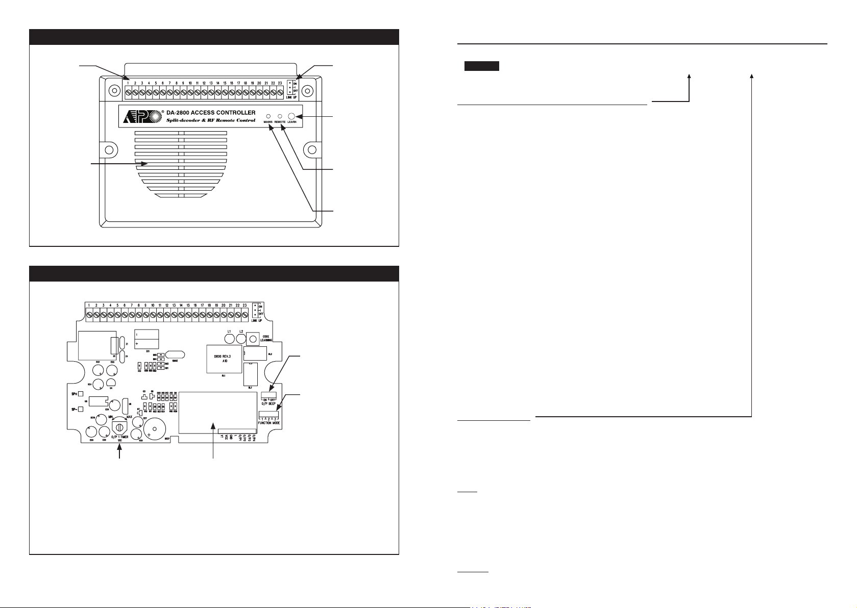
THE SPLIT-DECODED CONTROLLER UNIT (Figure 1)
CONNECTION
TERMINALS
INTERNAL SIREN
& DOOR CHIME
LINK-UP JUMPER
OFF-->ON-->OFF
CODE LEARNING
BUTTON
(DA-2800 ONLY)
REMOTE CONTROL
SIGNAL & STATUS
(DA-2800 ONLY)
MAINS
THE MAIN CIRCUIT BOARD OF THE CONTROLLER --- (Figure 2)
OUTPUT BEEP JUMPER
ON OR OFF
FUNCTION MODE JUMPER
1. SPLIT-DECODED
2. STAND ALONE MODE 1
3. STAND ALONE MODE 2
ADJUSTABLE TIMER
FOR OUTPUT 1
TURN CLOCKWISE FOR
MAXIMUM TIME
NOTE: Factory suggest that the work of timer adjustment and change of jumper settings on the main circuit board are
to be done by the Installer only.
No adjustment/setting change is required for Split-decoded operation with the ex-factory settings.
RECEIVER FOR
REMOTE CONTROL
(DA-2800 ONLY)
6
EGRESS DELAY , WARNING AND ALARM (Location 90)
FUNCTION MODES VALIDATIONDELAY TIMELOCATION
MASTER
CONFIGURATIONS OF THE EGRESS WARNING AND ALARM
Key in the number to enable 1 of the 6 configurations described below:
--- Momentary Contact Mode without Warning -- (Default)
1
• Press the Button once. No warning or alarm is given during Egress Delay.
• Good for silent area. The people have to wait for the door open until the delay time
reaches.
--- Momentary Contact Mode with Warning Beep
2
• Press the Button once. The system gives Warning Beeps during the Egress Delay.
• Good for the place required attention. The keypad beeps during the people are waiting for
the door open.
--- Momentary Contact Mode with Warning Beep & Alarm
3
• Press the Button once. The system gives Warning Beeps and also activates its Alarm O/P
during the Egress Delay
• Good for door for the authorized people only. The keypad beeps and report alarm to a
security system during the people are waiting for the door open.
• This is usually an “Emergency Exit”. The door can be opened with the Keypad without
triggering of the Buzzer and Alarm Output.
--- Holding Contact Mode without Warning
4
• Press and hold the Button. No warning or alarm is given during the Egress Delay.
• Good for the silent area. The people require to press & hold the button until the delay time
reaches for the door open.
--- Holding Contact Mode with Warning Beep
5
• Press and hold the Button. The system gives Warning Beeps during Egress Delay.
• Good for the place required attention. The keypad beeps while the button is kept pressed
during the people are waiting for the door open.
--- Holding Contact Mode with Warning Beep & Alarm
6
• Press and hold the Button. The system gives Warning Beeps and also activates its Alarm
O/P during Egress Delay.
• This is usually an “Emergency Exit”. The door can be opened with the Keypad without
triggering of the Warning and Alarm.
EGRESS DELAY TIMER
--- No Delay – (Default)
0
Output 1 activates instantly (the door is released instantly) when the Egress Button is pressed.
–
1
Put any number of 1 to 99 into the box to enable the Egress Delay. The number is the time in second, which starts to
count when the Egress Button is pressed. Output 1 activates (the door is released) when the delay time reaches.
NOTE:
1) Momentary Contact -- The Egress Delay starts to count when the egress button is momentarily pressed. Output 1
activates automatically (door is released) when the delay time reaches.
2) Holding Contact -- The user MUST hold the egress button in contact for the whole period of the Egress Delay time
until Output 1 activates. If the egress button is released before the end of the Egress Delay, the timer will stop to count
and reset.
3) The Egress Delay does not affect the operation of the User PINs/Cards for Output 1. The User PINs/Cards always
give INSTANT action.
Examples: (please see the following page)
--- Egress Delay Timing
99
37
1
-
6 0
or 1 -
99 #90
INTELLIGENT EGRESS BUTTON – AN UNIQUE FEATURE OF A CONTEMPORARY KEYPAD
Most of the keypads for access control are just for controlling of “Going In” from outside. It is not enough for today’s
access control systems. In fact, controlling of “Going Out” is also very important in many public passage areas. They
are not allowed to use locks or digital keypads for stopping of “Going Out” due to safety reasons. Such as hospitals,
kindergartens, elderly homes, convenient stores, emergency exits etc.. The wardens, teachers, shopkeepers and the
guards are always required to keep an eye on people to prevent unattended leaving, shoplifting, and illegal use of the
emergency exits.
The Intelligent Egress Button can be programmed to do something to get the attention of the person on duty before the
door is opened. The button offers programmable egress delay, delay with warning, holding button required for the delay,
momentary button contact with warning for the delay and even gives alarm when a controlled door is opened.
Locations 90 and 91 below are the places for setting the desired functions for the Egress Button.
The functions programmed to the Egress Button do not affect the normal operation of the system with its keypad. For
the safety consideration, the operation of the keypad with PIN, Code or Card is always in the first priority to give instant
action to the output relay 1 for door strike.
It is NOT required to program the Egress Button with the special function in normal use. Just leave it on its default
values.
INSTALLATION
PRECAUTIONS
1) Installation Location:
The built-in receiver of the Access Controller is working at the UHF frequency band of 433.92MHz. To get the best
receiving result of the signals from the remote keys a correct installation location is necessary.
i) Install it on a location inside the house facing to the open space and there has no strong electro-magnetic wave
signals near it.
ii) Do not install it in a concrete room or under a concrete stair, which shortens the control distance.
2) Prevent Accidental Short Circuit:
In the previous experience, most of the damages caused in the installation are accidental touching of the components
on circuit board with the wires carrying power. Please be patient in the installation. Study the manual to become
familiar with the specifications of the system beforehand is also important.
i) Do not apply power to the system while it is in installation.
ii) Check carefully all the wirings are correct before applying power to the system for testing.
WHERE AND WHY “GOING OUT” NEEDS ATTENTION
Examples for some areas may need an Intelligent Egress Button:
Hospital:
Some of the patients are not allowed to leave the ward without doctor’s permission. An egress button with exit delay
and warning beeps will help the nurse or warden to get the attention to the door when the egress button is pressed.
Further setting of the egress button with holding contact for the delay even gives higher level of security to a controlled
door.
Kindergarten:
Young children are always active. Some of them may be willing to go out to explore their ways of playing. For safety
reason, teachers have to watch all of them in the attended area. Leaving school alone without the companion of parents
or teacher is dangerous to the young children. An egress button with delay and warning beeps will be helpful to prevent
the children trying to go out without getting the attention of the teacher.
Elderly Home:
Elderly needs constant attention and care. Some old people have poor memory. They may forget the way to come
back if they leave home alone. An egress button with delay and warning beep will easily get the attention of the warden
before the door is open.
Convenient Store:
Most of the convenient stores have just only one or two shopkeepers on duty. They are usually the cashier. Shoplifting
may easily happen while the shopkeeper is busily serving customers at the cashier desk. A holding contact egress
button with delay and warning beeps may help to stop most of the shoplifting. As the thief knows that he is gotten
attention by the shopkeeper before the door is open.
High Traffic Passage:
A short buffer time may be necessary for opening a door outward after pressing the egress button for those exits open
to a high traffic passage. An egress button with shor t delay and warning beeps helps the user to pay attention to the
people passing by to prevent hitting them when the door is pushed outward.
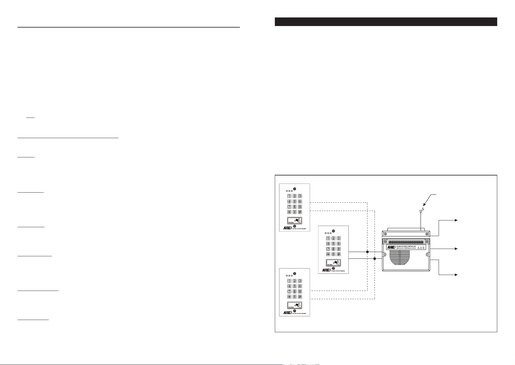
SPLIT-DECODED MODE -- (for DA-2800 & DA-2801)
Split-decoded Mode needs at least one keypad to work with the decoder. The decoder decodes all the commands
from the keypad to operate its outputs. It is an unique solution to immediately up-grade a general purpose keypad to a
high security access control system. All the keypads in the DK-2800 series with Data I/O Por t are compatible with the
decoder. A Split-decoded system divides itself into the outside keypad unit and the inside decoder unit. Any sabotage to
the outside unit does not affect the security of the inside unit.
RF WIRELESS
REMOTE CONTROL (DA-2800 ONLY)
DOOR LOCK
(OUTPUT 1)
SECURITY
SYSTEM (OUTPUT 2)
AUTOMATIC
OPERATOR (OUTPUT 3)
SLAVE 1
DATA I/O
COMMON
GROUND
DATA I/O
COMMON
GROUND
MASTER
DATA I/O
COMMON
GROUND
DA-2800 OR DA-2801
Emergency Exit:
Emergency Exit is not open to the public for daily use. It is for emergency case only. It is usually closed and watched
by the security guards. The egress button of this keypad can be programmed to offer exit delay with warning beeps and
even gives alarm output to trigger an alarm system when the door is forced to open or the door is open after the exit
delay expired. It is an useful tool to get the attention of the person on duty.
36
SLAVE 2
MAXIMUM 3 KEYPADS CAN BE CONNECTED IN PARALLEL
7
 Loading...