

AEI Protect On Systems AR2808 Users Manual
Self-Contained
Access Control Reader
AR-2808
User Manual
AEI PROTECT-ON SYSTEMS LIMITED
www.apo-hk.com
VERSION: 05/2013

TABLE OF CONTENTS
...................................................................................................................... 3
INTRODUCTION
................................................................................................................... 3
SPECIFICATIONS
................................................................................................................ 3
Package Contents
................................................................................................................ 4
THE FRONT PANEL
.......................................................................................................... 4
Status Indicator (Blue)
............................................................................................................. 4
Operation Indicators
Card Reader Window
Door Bell Button (Function Selector)
INSTALLATION
Precautions for Installation Location
Precautions for Accidental Short Circuit
Precautions for Electric Spikes & Back EMF
............................................................................................. 6
THE CONNECTION TERMINALS
.................................................................................... 6
1 - 2 : 12VDC (Power Input Terminal)
3 : (+) 12V Power Supply for The Lock
4 : (-) Power Supply for The Lock (Output Contact for Door Lock Strike)
5 : EG IN (Egress Input for N.O. Button)
6 : Data I/O Port
7 - 8 : Door Bell (Relay Contact for Optional Door Chime)
9 - 10 : Tamper Switch (Tamper Switch with N.C. Contact)
CREATE A MASTER CARD (CMC)
The First Step before Programming - Make A Madter Card
Procedures of Creating A New Master Card with CMC Jumper
PROGRAMMING
1) Criteria for Setting System to Programming Mode
2) Use The Master Card to Set System into Programming Mode for The 5 Feature Groups
3) The Reading Manner for Master Card
................................................................ 9
4) Audible Indications in Programming & Operation
I ) RECORD USER CARD(S) – Feature Group 1
II ) DELETE USER CARD(S) – Feature Group 2
III ) SET OUTPUT MODE FOR DOOR LOCK -- Feature Group 3
IV ) SET SYSTEM SAFETY LOCK-UP -- Feature Group 4
V ) CREATE / DELETE SUPER USER CARD(S) -- Feature Group 5
OPERATION
FEATURE SETTING PROCEDURES SUMMARY CHART
APPLICATION EXAMPLES
1) Stand Alone Access Control Electric Lock
2) Application Hints for The Auxiliary Terminals
APPLICATION EXPANSION – The Optional Auxiliary Reader AR-2802
Multi- Station Access Control Electric Lock
............................................................................................................ 4
...................................................................................... 4
........................................................................................................................ 5
.......................................................................... 5
.................................................................................. 6
..................................................................................................................... 7
..................................................... 7
.............................................. 8
....................................................................................................................... 9
.. 9
................................................................... 10
.............................................................................................................................. 17
...................................................................................... 5
................................................................................ 5
................................................................................ 7
.................................................... 7
.......................................................................................... 8
................................................................................. 9
..................................................................................................... 20
......................................................................... 20
..................................................................... 20
............................................................................ 22
.................................................... 8
............................................................... 9
.............................................................. 11-12
...................................................... 14
................................................. 18-19
................................ 6
........................................... 13
................................. 15-16
............................. 21
2
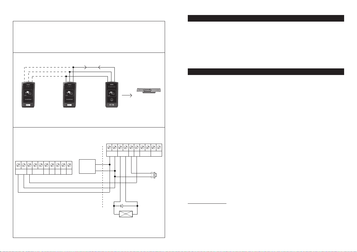
Multi- Station Access Control Electric Lock
Description
The AR-2808 is expandable to a multi-station system for user convenience with the auxiliary
reader AR-2802. Maximum 3 AR-2802 can be connected in parallel with the Data I/O Bus of
the AR-2808. The auxiliary reader(s) reads the Cards as like the master reader AR-2808
which is the server of the system to manage the data from the auxiliary reader(s).
System Connection
DATA I/O BUS
– ) GND
COMMON(
(
+ ) POWER SUPPLY
ELECTRIC
LOCK
AR-2802
AUXILIARY
READER
AR-2802
AUXILIARY
READER
Wiring Diagram
AR-2802 AUXILIARY READER (S)
DATA
TAMPER
( + ) ( – )
I/O
12VDC
N.C.
More AR-2802 can be connected in parallel.
LED D1
COMMON GND
D0
10987654321
RS232BUZ
DATA I/O BUS
( – )
( + )
12VDC
POWER
SUPPLY
AR-2808
THE SERVER
AR-2808 MASTER READER (THE SERVER)
( + ) ( – )
( + ) ( – )
12VDC
( + )
( – )
( + ) ( – )
DOOR LOCK
ELECTRIC
1N4004
LOCK
DATA
I/OEGIN
DOOR BELL
N.O.
*JUMPER SELECTION
FOR ELECTRIC LOCK OF
(1) FAIL-SAFE OR
(2) FAIL-SECURE
TAMPER
N.C.
EGRESS
BUTTON
N.O.
INTRODUCTION
AR-2808 is a self-contained access control reader designed to drive electric door lock directly. It
accommodates up to 500 proximity EM cards and its output is compatible with the Fail-safe and
Fail-secure electric locks. The door lock striking time is programmable. A built-in door chime relay
contact is also available to operate an external low power door chime. It is a full feature compact
reader ideally for the access control system in small office and home applications. The system
employs solid state switch instead of relay contact for door lock strike. It gives longer service life and
prevents the sabotage of opening the door with strong magnet.
AR-2808 is built-in with Data I/O bus for system expansion. Maximum three optional card readers
(AR-2802) can be connected with it to make a multi-station access control system.
SPECIFICATIONS
● Operation Voltage: 12VDC Nominal, 11-16VDC
● Operating Current: 60mA (quiescent), 80mA Maximum
● Operation Temperature: -20°C to +70°C
● Environmental Humidity: 5-95% Relative Humidity, Non-condensing
● Working Environment & Ingress Protection: Indoor or Outdoor, IP-55 Weatherproof
● Number of User Cards: 500, Standard 125Khz Proximity EM Cards or Keyfobs
● Number of Super User Cards: 5, Standard 125Khz Proximity EM Cards or Keyfobs
● Safety Lock-ups: a) No Lock-up, b) Auto Lock-up after Invalid Trials, & c) Manual Lock-up with
iiiiSuper User Card
● Door Lock Operating Timer: 1-60 Seconds Programmable
● Egress Button: Normally Open (N.O.) Button(s) for Request to Exit from Inside
10987654321
● Data I/O Bus for Optional Card Readers (AR-2802). Accommodates 3 Optional Readers Max.
● Bell Button: Output Relay Contact for Actuating An Optional Door Chime
● Output Contact Ratings:
iiiia) Solid State Output for Lock Strike – Fail-safe or Fail-secure Selectable, 3A/16VDC Max.
iiiib) Door Chime Relay – N.O. Dry Contact, 1A/24VDC Maximum
iiiic) Tamper Switch – N.C. Dry Contact, 50mA/16VDC Maximum
● Dimensions: 60(W) X 119(H) X 23(D) mm
● Weight: 160g Net
● Housing: ABS Plastic
Specifications are subject to change for modification without notice
PACKAGE CONTENTS
● One AR-2808 Reader
● Two EM Cards
● One Pack of Mounting Screws
● One User Manual
22
3
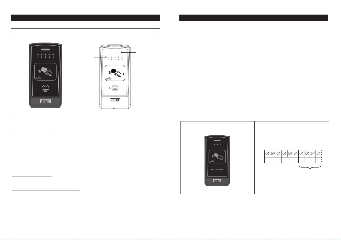
THE FRONT PANEL
APPLICATION EXPANSION – The Optional Auxiliary Reader AR-2802
AR2808 FRONT PANEL
Status Indicator
(Blue)
Card Reader
Window
●
Status Indicator (Blue)
Operation Indicator
Door Bell Button
(Function Selector)
It is ON in normal operation. It flashes during programming mode or lock-up mode.
●
Operation Indicators
The 5 LED indicators with number 1, 2 ,4 and 5 in green and number 3 in amber color show the
status of the system in Operation Mode or in Programming Mode.
1) They indicate the Storage Group of an EM card when it is read in Operation Mode.
2) They show the status of feature settings in Programming Mode. See “Programming” &
“Operation” sections for the details.
●
Card Reader Window
It is a place for reading EM cards.
●
Door Bell Button (Function Selector)
This button has two functions. It is a door bell button in normally operation and is a function
selector in programming mode. See the details in “Programming” & “Operation” sections.
Apart from standard-alone operation, AR-2808 is expandable to be a Multi-station System with the
optional auxiliary reader AR-2802. Maximum three optional readers can be allowed and the
connection is very simple. Just connect the devices in parallel with the Data I/O Bus of the
AR-2808. The AR-2808 acts as a server of the system and manages the data among them.
A Multi-station System provides higher security in access control and user convenience to operate
an electric lock at different locations. Such as a dual reader system for area needs controlling of
going in and going out with proximity EM cards.
The optional reader is available in standard version (AR-2802S) and advanced version
(AR-2802A). The advanced version also provides Wiegand and RS-232 data outputs for custom
project development with access control panel and / or PC.
The AR-2802 is also compatible with all the Tri-Tech keypads in the 2nd generation DK-2800
series for system expansion.
*Please contact your local agent for the optional reader if system expansion is required.
The Auxiliary Reader AR-2802 And It’s Connection Terminals
Connection TerminalsAuxiliary Reader
10987654321
( + ) ( – )
12-24V DC
DATA
TAMPER
I/O
N.C.
LED
BUZ
AR-2802A ONLY
WIEGAND
D0 D1
RS
232
4
21
 Loading...