

Page 1
Gas and mixed fuel cookers
INSTRUCTION BOOKLET
35674-7603
Mod. 65 G - 66 GS - 66 EX-T - 95 G - 95 GS - 95 ES - 95 GX - 95 GX-T - 95 EX-T
Page 2

ENGLISH
Important Safety Information
It is very important that this instruction book should be kept safely for future consultation. If the appliance should be sold
or given to another person, please ensure that the booklet goes together with it, so that the new owner can know of the
functions of the machine and also be aware of the warnings.This warnings has been given for the safety of you and
others. We therefore ask you to carefully read the procedures of installing and using this cooker.
Installation
The work of installation must be carried out by
competent and qualified installers according to the
regulations in force.
Any modifications to the domestic electrical mains
which may be necessary for the installation of the
appliance should be carried out only by competent
personnel.
It is dangerous to modify, or attempt to modify, the
characteristics of this appliance.
Avoid installation of the cooker near inflammable
material (e.g. curtains, tea towels, etc.).
Child Safety
This appliance has been designed for use by adults.
Take care, therefore, that children do not attempt to play
with it.
The appliance remains hot for a long time after being
switched off. Supervise children at all times, paying
attention that they do not touch surfaces or remain in the
vicinity of the appliance when in use or when not
completely cooled.
During Use
This product is intended for the cooking of food and
must not be used for other purposes.
During cooking on the grill or in the oven, the unit is kept
at a high temperature in relation to the plate glass door
and adjacent parts. Take care therefore, that children do
not play near it. When connecting household appliances
to a plug near the unit, ensure that they are kept away
from the flame and the oven door.
During the first minutes of use, the thermal insulation
of the oven, and residual grease from manufacture, produce smoke and disagreeable smells. On first use, we
advise heating the oven, empty, for approximately 45
minutes. Then leave to cool and clean the inside of the
oven with hot water and a mild detergent.
Unstable or deformed pans should not be placed on the
burners or plates in order to avoid accidents caused by
upsetting or boiling over.
Particular care should be taken when cooking with oil
or fat.
If the appliance is fitted with a cover, its function is to
protect the surface from dust when closed and to accumulate splashes of grease when open. Do not use for
other purposes.
Always clean the cover before closing.
Leave the burners and/or plates to cool before closing.
All the covers, in plate glass or enamel, are removable
to facilitate cleaning.
Always ensure that the knobs are in the «
position when the appliance is not in use.
Always insert the dripping pan when using the grill or
when cooking meat on the grid. Pour a little water into
the dripping pan to avoid grease burning and creating
unpleasant smells.
» (Stop)
Always use oven gloves to remove dishes from the oven.
Maintenance and Cleaning
Before maintenance and cleaning disconnect the
appliance and allow to cool.
For reasons of hygiene and safety this appliance must
always be kept clean. A build up of grease or other food
can cause fires.
The accessories (grid and dripping pan) should be
washed before using for the first time.
Take care when using cleaning products in spray form:
never direct the spray onto the resistance or the
thermostat bulb.
If, when placing food in the oven, or when removing it, a
large quantity of oil, juice, etc. spills onto the bottom of
the oven, re-clean before starting to cook to avoid
unpleasant smoke and also the possibility of these
substances catching fire.
Ensure that air can circulate around the gas appliance.
Poor ventilation can produce a lack of oxygen.
The use of a gas cooking appliance produces heat and
humidity in the room in which it is installed. Ensure
good ventilation of the room keeping natural ventilation
openings clear or installing an extractor hood with a
discharge tube. In case of doubt ask installer for advice.
Supply the appliance with the type of gas stamped on
the relevant adhesive label situated in the immediate
vicinity of the gas connection tube.
The gas oven becomes hot with the movement of air.
The holes on the bottom of the oven must never be
obstructed. Do not cover the sides of the oven with
aluminium foil, in particular the lower part of the
opening.
The appliance is heavy, move it carefully.
To facilitate ignition, light the burners before placing
pans on the grid. After having lit the burners check that
the flame is regular.
Always lower the flame or turn it off before removing the
pan.
Ensure that the oven grids are inserted correctly.
Only heat-resistant plates may be placed in the drawer
situated under the oven. Do not put combustible
materials there.
Service
In case of repairs, do not attempt to correct yourself.
Repairs carried out by unqualified persons can cause
damage. Contact an authorized Technical Assistance
Centre and insist on original spareparts.
Environmental Information
After installation, please dispose of the packaging with
due regard to safety and the environment.
When disposing of an old appliance, make it unusable, by
cutting off the cable. Remove any door catches, to prevent
small children being trapped inside.
2
Page 3
Contents
Instructions for the user
Important Safety Information 2
Dimensions of the appliances 3
Using the cooker hob 4
Hints and tips 6
Using the Gas Oven 7
Using the Electric Oven 9
Before the first Use of the Oven 9
Suggestions for the use of the gas burners 10
Suggestions for the use of the oven 10
Cooking tables 12
Maintenance 13
Guide to Use the instructions
The following symbols will be found in the text to guide
you throughout the Instructions:
Safety Instructions
Step by step instructions for an operation
F
Hints and Tips
Instructions for the installer
Instructions for the Installer 14
Gas connection 15
Adaptation to different kinds of gas 16
Insertion possibility 17
Technical data 18
Electrical connection 19
Something not working 19
This appliance complies with the following
E.E.C. Directives:
73/23 - 90/683 (Low Voltage Directive);
89/336 (Electromagnetical Compatibility
Directive);
90/396 (Gas Appliance Directive);
93/68 (General Directives);
and subsequent modifications.
MANUFACTURER:
ELECTROLUX HOME PRODUCTS ITALY S.p.A.
Viale Bologna 298
47100 FORLÌ (Italy)
Environmental information
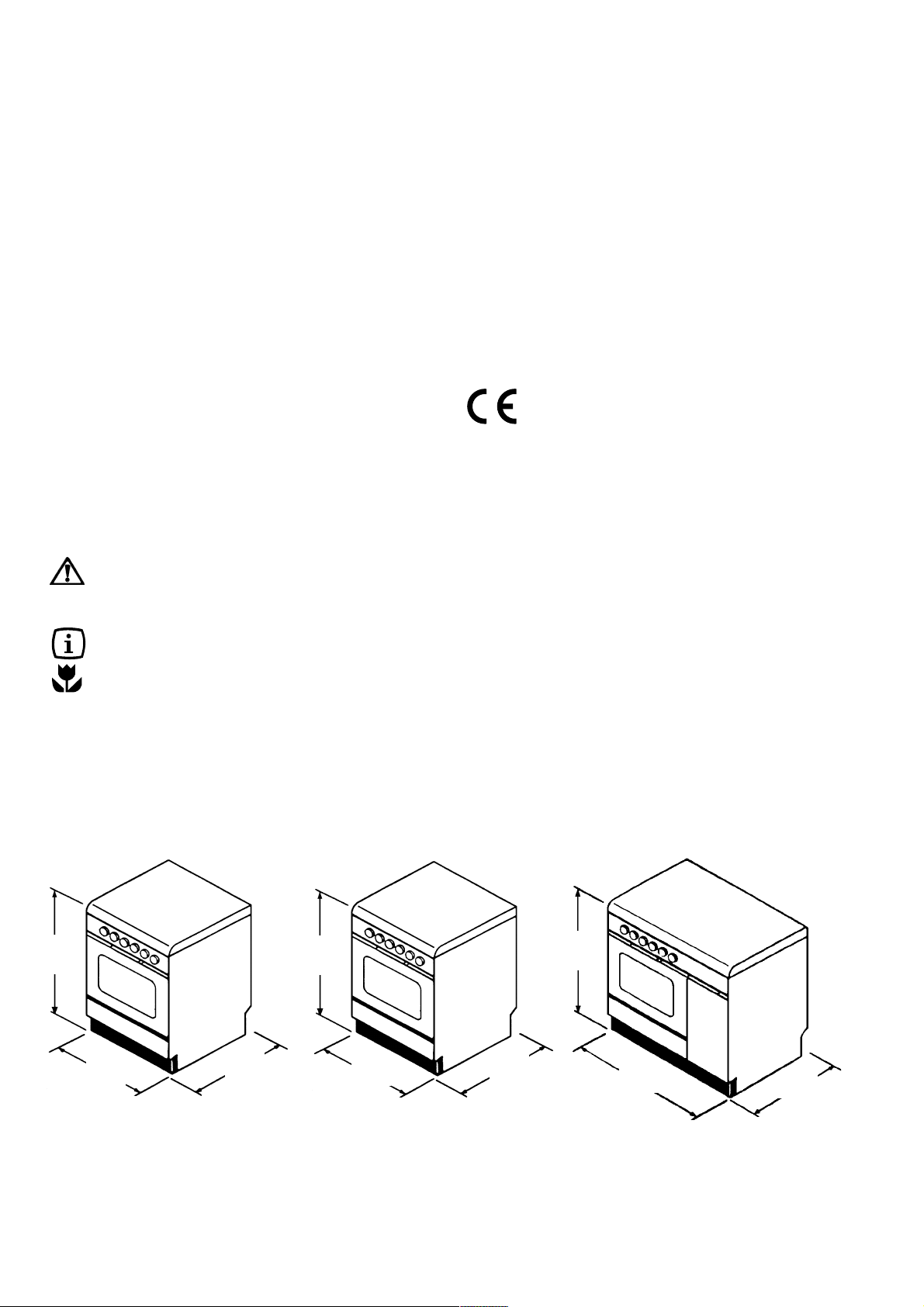
Dimensions of the appliances
850
600
600
850
600
500
850
900
550
3
Page 4
Using the cooker hob
Control knobs on the gas hob
(Fig. 1)
The knobs for using the gas hob of the cooker are
found on the control panel. The regulation knobs could
be turned in anti-clockwise direction until the small
flame symbol, and vice-versa for the larger symbol.
No gas supply
Maximum gas supply
Minimum gas supply
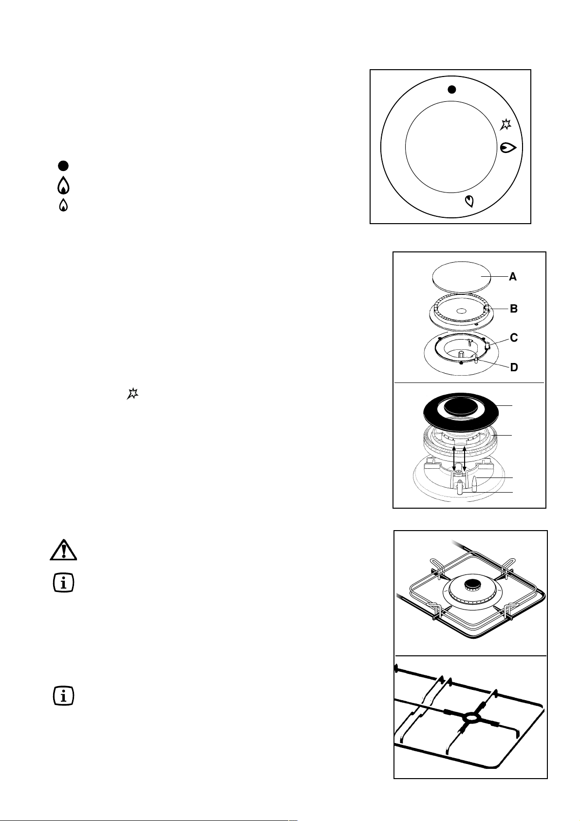
Fig. 1
Ignition of hob burners
FO 1079
To ignite a burner, before positioning the saucepan,
proceed as follows:
1. push the corresponding knob in completely
F
Mod. 65 G - 95 G
F
In models provided with a safety device
("thermocouple", Fig. 2-D), the control knob must be
pressed in for approximately 5 seconds until the
safety valve automatically keeps the flame lit.
If after a few attempts the burner does not ignite, check
that the burner cap and crown (Fig. 2-A,B) are correctly
positioned.
To interrupt the supply of gas, turn the knob in a
clockwise direction to the position "l".
and turn in anticlockwise direction to the
maximum position;
2. upon ignition regulate the flame as required.
1. push the relevant control knob in completely
and turn in an anticlockwise direction to the
maximum position;
2. press the ignition switch marked by a small
spark ( );
3. upon ignition regulate the flame as required.
A - Burner Cap
B - Burner crown
C -Spark generator
D - Thermocouple
FO 0204
A
B
D
C
Fig. 2
During cooking, when using fats or oils, take
particular care as they can, when overheated, self-ignite.
When using the triple-crown burner, place
the special grid on the pan support (Fig. 3-A).
When using the auxiliary burner (with pans
having a diameter equal or higher than
50mm), place the special grid on the pan
support, as shown in Fig. 3-B.
Triple-crown burner
In models provided with triple-crown burner, always
ignite the burner before putting the pans on.
If after a few attempts the burner does not ignite, check
that the burner cap and crown are correctly positioned.
4
A
B
Fig. 3
Page 5
Control knob for the hotplates
The hotplates control knob (65 G, 66 EX-T, 95 ES, 95
GX-T, 95 EX-T) can be adjusted on four different
positions, according to your cooking needs, from
maximun heat (position 4) to minimum heat (position
1), as shown in Fig. 4.
0
4
1
3
Fig. 4
Table of minimum and maximum diameters of
recipients to be placed on burners
Burner min diam max diam
Triple-crown ø 160 mm ø 260 mm
Rapid ø 160 mm ø 260 mm
Semi-rapid ø 120 mm ø 220 mm
Auxiliary ø 80 mm ø 160 mm
FO 2193
2
5
Page 6
Hints and tips
Pottery
Remember that a wide-bottomed pan allows a faster
cooking than a narrow one.
Always use pots which properly fit what you have to
cook.
Particularly make sure that the pans are not too small
for liquids, since these could easily overflow.
Moreover, the pans should not be too large for a faster
cooking. In fact, grease and juices may spread on the
bottom and burn easily.
It is better to use non-openable moulds for baking cakes.
In fact, an openable mould lets juices and sugar leak
through, falling on the bottom of the oven and
consequently burning on the bottom of the baking tray,
making cleaning difficult.
Avoid putting plastic-handled pans in the oven as they
are not heat-proof.
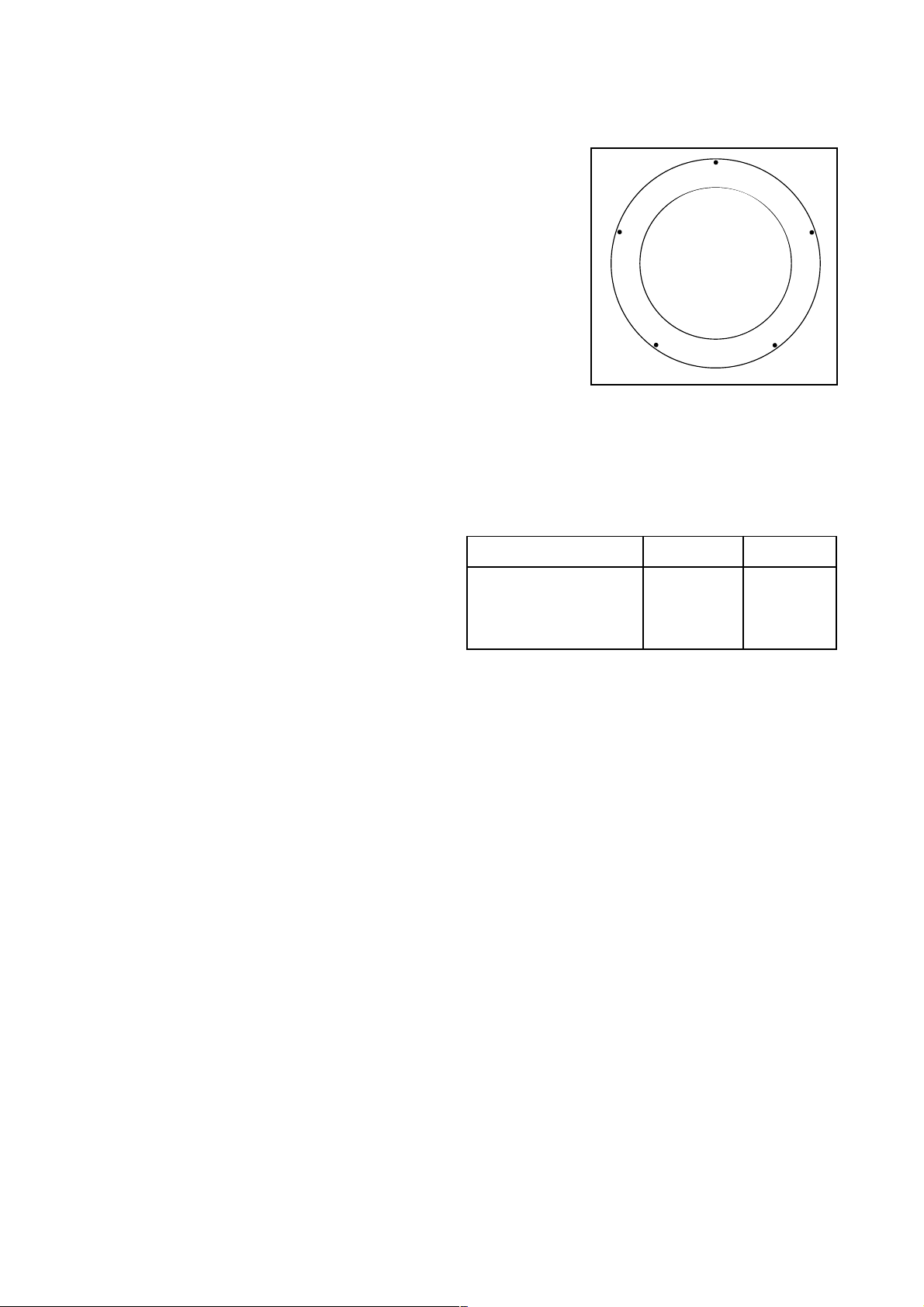
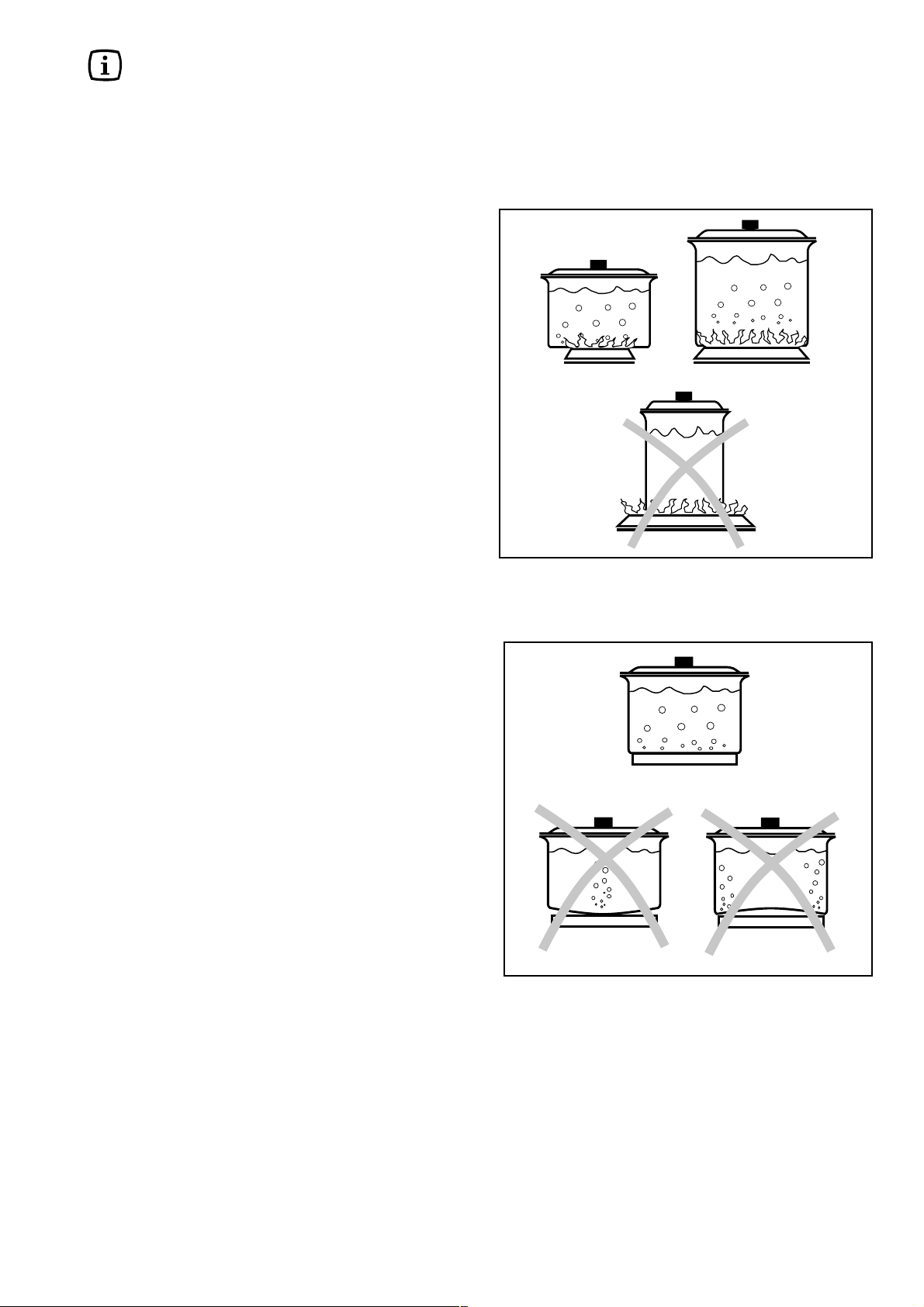
You should use pans with the right diameter to fit the
burner, in order to make the most out of it, thus reducing
gas consumption as in Fig. 5.
It is also advisable to cover any boiling casserole and,
as soon as the liquid starts boiling, lower the flame
enough to keep the boiling point.
Fig. 5
Hotplates
Saucepans suitable for use on solid plate hobs should
have several characteristics:
they should be fairly heavy duty;
they should fit the heat area exactly, or be slightly
larger for efficient use, NEVER smaller;
they should have a flat base to ensure good contact
with the plate (see Fig. 6).
This is particularly important when using pans for high
temperature frying or pressure cooking.
Ensure pans are large enough to avoid liquids being spilt
onto the plates.
Never leave the plates on without a pan on them or with
an empty pan on them.
In models supplied with a cover, if it is made of
glass, it should not be closed when the burners are
still hot, as it could splinter.
Fig. 6
6
Page 7

Using the Gas Oven
(65 G - 66 GS - 66 EX-T - 95 G - 95 GS - 95 GX - 95 GX-T)
Ignition
F
1. Open the oven door, then push and turn the oven knob
(Fig. 7) in anti-clockwise direction to the maximum temperature position;
2. Upon ignition keep the knob pushed in for about 5 seconds.
Mod. 65 G - 95 G
F
open the oven door and hold a flame near the hole in the
bottom as shown in Fig. 8;
press the oven knob and turn anti-clockwise until the
maximum temperature position is reached;
press in the oven knob for approximately 5 seconds until
the safety valve automatically keeps the oven burner lit.
If the burner does not light first time, keep the oven door open
and wait 1 minute at least before repeating the operation.
Once the oven has been lit, adjust the flame as required.
If the flame should accidentally go out, turn the oven knob
at the "off" position (symbol "l") and wait 1 minute at least
before retrying to light the burner.
Ignition of the oven burner must be carried out with
the oven door open.
When cooking with the oven or grill, the cover
must be kept open to avoid over-heating.
To adjust automatically the flame in cookers equipped with
thermostat (Fig. 7), turn the knob to the position
corresponding to the temperature desired, after a few minutes
of work.
Fig. 7
Mod. 65 G - 95 G
min
150
175
250
Mod. 66 GS-66 EX-T-95 GS-95
GX-95 GX-T
220
min
150
175
250
FO 2276
220
Grill burner ignition
F
Open the oven door;
turn the oven knob (Fig. 7) on the Grill symbol . Upon
ignition, keep the knob pushed in for about 5 seconds.
For manual ignition:
open the oven door and hold a flame near the gas grill
burner holes, as shown in Fig. 9;
press the oven knob and turn it clockwise until it points
on the Grill symbol ;
keep the oven knob pushed in for about 5 seconds until
the safety valve automatically keeps the oven burner lit.
If the burner does not light first time, repeat the operation
keeping the knob pressed in slightly longer. Once the oven
has been lit, adjust the flame as required.
Electric grill (65 G only)
In the models with gas oven press and turn the knob clockwise
until position ; at the same time the grill light will come on.
Place the dripping pan under the wire shelf so as to prevent
fat from dripping on the bottom of the oven.
Oven light switch
Fig. 8
Fig. 9
FO 1079
FO 0829
It allows the oven internal light to be switched on.
7
Page 8
0
5
01
51
0
3
04
05
0
2
Turnspit
F
(66 GS, 66 EX-T, 95 GS, 95 ES, 95 GX, 95
GX-T, 95 EX-T)
For correct use, proceed as follows (Fig. 10):
fit the spit support into the third runner from the
bottom;
slide the spit into the food to be cooked and secure
well;
rest the front part of the spit on the hook, ensuring
that the point of the spit is well inserted into the
rotisserie motor housing (Fig. 10);
remove the handle;
turn the oven knob to the grill position or, when
required for some models, turn on the motor by
means of the appropriate switch .
When cooking with the rotisserie and the
grill, you are advised to leave the oven door
half open and to fit the knob protection
shield as shown in Fig. 11.
Fig. 10
FO 0329
Mechanical minute-minder
The minute-counter may be set for a maximum time of
one hour. The regulation knob (Fig. 12) must be turned
clock-wise until the 60-minute position is reached and
then anti-clockwise to the required time.
Once the pre-set time has elapsed, a signal will be
heard which automatically cuts out. The oven, however,
will remain on.
Fig. 11
FO 2124
FO 0375
8
Fig. 12
FO 2244
Page 9

Using the Electric Oven
(95 ES - 95 EX-T)
Oven Function Control knob
(Fig. 13)
It makes it possible to choose the most appropriate
temperature and to select the elements radiating heat
one by one.
The oven light stays lit in all selector positions.
Explanation of symbols:
0 Oven in off position
Oven light
50-max Temperature
Top heating element - The heat comes
from the top of the oven only
Bottom heating element - The heat
comes from the bottom of the oven only
Grill - The heat comes from the top
element only
To select the temperature, turn the knob clockwise until
the pointer is on the position indicating the desired temperature, included between 50° C and max.
The temperature will be kept constant by the
thermostat.
If you want more heat coming from the bottom or more
heat coming from the top turn the knob so as to place
the pointer on the symbol (bottom heat) or (top
heat).
Under these conditions the temperature will never
exceed about 200° C in the bottom heat position
and 180° C in the top heat position and it will not
be regulated by the thermostat.
0
0
5
0
10
0
5
Fig. 13
1
FO 1196
2
0
0
Electric grill
In the models with electric oven press and turn turn the
knob clockwise until position ; at the same time the
grill light will come on.
Place the dripping pan under the wire shelf so as to
prevent fat from dripping on the bottom of the oven.
Appliances Width 90 cm: When using the grill,
the oven door must be kept half-open and the
knobs-protection shield (Fig. 11) must be in
position.
Operation pilot light (Red light)
When lit, it shows the insertion of one or more heating
elements.
Oven thermostat pilot light
(Yellow light)
It turns off when the oven reaches the selected temperature and re-lights when the heating elements operate
to stabilize the temperature.
Before the First Use of the Oven
Remove all packaging, both inside and outside
the oven, before using the oven.
Before first use, the oven should be heated without food.
During this time, an unpleasant odour may be emitted.
This is quite normal.
1. Set the oven function control knob to MAX.
F
2. Open a window for ventilation.
3. Allow the oven to run empty for
approximately 45 minutes.
This procedure should be repeated with the grill function
for approximately 5-10 minutes.
9
Page 10
Suggestions for the use of the gas
burners
Start your cooking with a big flame by turning the knob
to the symbol . Then adjust the flame as necessary.
The outside of the flame is much hotter than its inside
(nucleus). Accordingly , the top of the flame should lick
the bottom of the pan. Excessive flames mean a waste
of gas.
In contrast with electric grids, gas burners do not require
flat-bottomed pans: the flames lick the bottom and
spread the heat all over the surface.
No special pans are required for gas burners. However,
thinwalled pans transmit the heat to the food more
quickly than thick-walled ones.
Since heat doesn't spread evenly on the pan's bottom,
the food may only be partially heated. Consequently it
is advisable to stir the food many times.
A thick pan bottom prevents partial overheating as it
allows sufficient thermic compensation.
Avoid very small pans. Wide and shallow pans are more
suitable than narrow and deep ones as they allow a
faster heating. Cooking is not quickened by placing
narrow pans on wide burners. The result is just a waste
of gas. For a proper usage, place small pans on small
burners and large pans on large burners.
Remember to cover pans to reduce gas consumption.
Suggestions for the use of the oven
Traditional cooking
Heat derives from the top and the bottom, it is therefore
preferable to use the central guides. If cooking requires
more heat from the bottom or the top, use the upper or
lower guides.
Advice for use of the traditional
oven (gas and electric)
For the cooking of cakes
Pre-heat the oven , unless indicated differently, for at
least 10 minutes before use. Do not open the oven
door when cooking dishes which must raise (e.g. raised
pastries and soufflés); the jet of cold air would block
the raising process. To check if cakes are cooked,
insert a toothpick into the mixture; if it comes out clean
the cake is ready. Wait until at least 3/4 of the cooking
time has passed before doing this check.
As a general rule remember that:
a dish which is well-cooked on the outside but not
sufficiently cooked inside would have required a lower
temperature and longer cooking time. On the contrary,
a dry texture would have required a shorter time and
higher cooking temperature.
For the cooking of meat
Meat to be cooked in the oven should weigh at least 1
kilo to avoid its becoming too dry. If you want roasts
with a good colour, use very little oil. If the piece is lean,
use oil or butter or a little of both. Butter or oil are on
the other hand unnecessary if the piece has a strip of
fat.
If the piece has a strip of fat on one side only, put it in
the oven with this side upwards; when melting the fat
will grease the lower side sufficiently.
Red meat should be removed from the fridge one hour
before cooking otherwise the sudden change of temperature could cause it to become tough. A roast,
especially if of red meat, must not be salted at the
beginning of cooking as salt causes juices and blood to
seep out of the òmeat, thus preventing the formation of
a well-browned crust.
It is advisable to salt the outside of the meat after just
over half the cooking time.
Place the roast in the oven in a dish having a low rim;
a deep dish shields heat.
10
Page 11

Meat can be placed on an ovenproof dish or directly on
the grill, under which the dripping pan will be inserted
to collect juice. Ingredients for gravy should only be put
in the dish immediately if cooking time is brief,
otherwise they should be added during the last half
hour.
Begin cooking rare meat at a high temperature,
reducing the temperature to finish cooking the inside.
The cooking temperature for white meat can be moderate throughout.
The degree of cooking can be checked by pressing the
meat with a fork; if it does not give the meat is cooked.
At the end of cooking it is advisable to wait at least 15
minutes before cutting the meat in order that the juices
are not lost.
Before serving plates can be kept warm in the oven at
minimum temperature.
For the cooking of fish:
Cook small fish from start to finish at a high temperature. Cook medium-sized fish initially at a high temperature and then gradually lower the temperature.
Cook large fish at a moderate temperature from start to
finish.
Check that baked fish is cooked by gently lifting one side
of the gut; the meat must be white and opaque
throughout, except in the case of salmon, trout or
similar.
when preparing the same dishes, in the same
conditions, similar results are obtained.
The TABLE OF COOKING TIMES relating to cooking
in the oven and by grill is provided as a guide.
Experience will show possible variations to the values
set out in the table.
Nevertheless carefully follow the indications given
in the receipe you intend to follow.
Attention: do not place any utensils such as dripping
pan, cake tins, casseroles, pyrex dishes, aluminium foil
or other on the base of the oven when the oven is in use.
A stagnation of heat would result which would compromise the results of cooking and could damage the oven
enamel.
Grilling
The following types of meat are suitable for grilling.
Mostly meat or offal cut in slices or pieces of various
sizes, but not usually very thick, poultry cut in half and
flattened, fish, some vegetables (e.g. courgettes,
aubergines, tomatoes, etc.), skewers of meat or fish and
seafood.
Meat and fish to be grilled should be lightly brushed with
oil and always placed on the grill; meat should be salted
upon completion of cooking; whereas fish should be
salted on the inside before cooking. The grill should be
positioned in the guides nearest or furthest from the grill
element according to the thickness of the meat, in order
to avoid burning the surface and cooking the inside
insufficiently.
The formation of smoke caused by drops of juice and
fat can be avoided by pouring 1 or 2 glasses of water
into the dripping pan.
The grill can also be used to brown, toast bread and grill
certain types of fruit, such as bananas, halved grapefruit,
slices of pineapple, apples, etc. Fruit should not be
placed too near the source of heat.
Cooking times
Cooking times can vary according to the type of food,
its consistency and its volume. It is advisable to watch
when cooking for the first time and check results since
11
Page 12
Cooking tables
Kinds of food
Beaten mixture cakes in moulds
Black and white flour cake 175 2 2 60-70
Royal flat bread-cake 175 2 3 60-70
Margherita cake 175 2 3 35-40
Pastry
Bottom of cake to be garnished 200 2 3 15-20
Butter-milk curd cake 200 1 2 35-40
Jam cake 200 1 2 35-40
Leavening dough cakes in moulds
Brioche 200 2 2 35-40
Small cakes
Pastry 170 2 3 10-15
Cream puff 200 2 3 30-40
Meringue 140 2 3 120
Lasagne 225 2 2 40-50
Meat (cooking time for every cm of thickness)
Long cooking roast meat 175 2 2 12-15
Short cooking roast meat 200 2 2 10-12
Meat-loaf 200 2 2 30-40
Poultry
Duck 1 1/2 - 2 kg 200 2 2 120-180
Goose 3 kg 200 2 2 150-210
Roast chicken 200 2 2 60-90
Turkey 5 kg 175 2 2 about 240
Game
Hare 200 2 2 60-90
Roe-deer rib 200 2 2 90-150
Deer haunch 175 2 2 90-180
Vegetables
Boiled vegetable flan 200 2 2 40-45
Fish
Grey mullets 200 2 2 40-50
Pizza 240 1 2 20-25
Grill
Chops 3 3 15-20
Sausages 3 3 20-25
Grilled chicken 2 2 60-70
Roast veal on the spit 0,6 kg 70-80
Chicken on the spit 60-90
Temperature
°C
Inserting slide*
Ordinary
electric oven
Gas oven
Cooking
time in
minutes
* The number of the slide refers to the lowest one (excepted the position on the bottom of the oven, since the dripping pan
can't be inserted).
Grilling
TRADITIONAL GRILL COOKING
Tipes Quantity kg N. of the slide from the bottom Temperature °C Time in
(grill position) Minutes
Chicken 1-1,5 3 Max 30 a side
Toast 0,5 4 Max 5 a side
Sausages 0,5 4 Max 10 a side
Chops 0,5 4 Max 8 a side
Fish 0,5 4 Max 8 a side
12
Page 13
Maintenance
Before each operation, disconnect the unit.
Cleaning the oven
Clean carefully the oven cavity after use when it is still
warm. In fact, at this moment it is easy to take off
deposits of fat or other substances such as fruit juice,
sugar particles or fat. You can use warm detergent water
or one of the appropriate spray oven cleaners. Do not
direct the spray at the mat steel parts as this could
damage them and always follow the manufacturer's
instructions. Clean the oven accessories (grate, gridplate etc.) with warm water and detergent.
Remove possible incrustations with a slightly abrasive
powder.
Never line any part of the oven with aluminium foil. It
would result in an accumulation of heat which might
damage the cooking results and also damage the
enamel.
Controls - Sundries
Appliances Width 60 cm
FO 0287
Appliances Width 90 cm
Periodically check the condition of the flexible pipe of
gas connection and make it replaced by skilled
technicians as soon as it shows abnormalities. Annual
replacement is recommended.
Have the cocks periodically lubricated by skilled
technicians. In case of unusual working have the range
checked by skilled technicians.
In ranges with cylinder holder, do not use this space to
leave a non-connected or an empty cylinder.
Cylinder holder
The units equipped with cylinder holder must be installed
in such a way to ensure a sufficient ventilation inside the
holder itself; otherwise there is the chance to install
inside the holder, instead of the cylinder, (on request) a
set of grills and containers, converting the cylinder holder
into a comfortable closet.
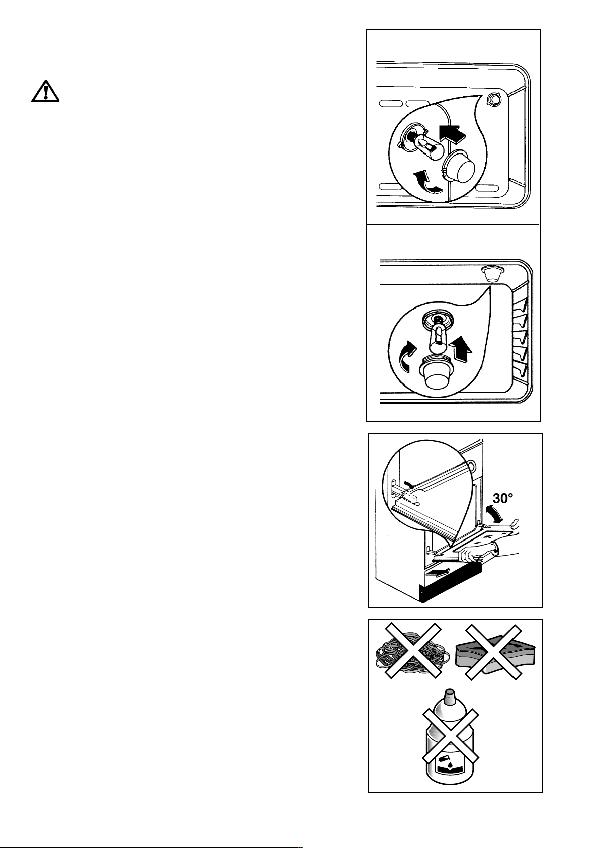
Oven lamp replacement
Disconnect the appliance. Unscrew the lamp (Fig. 14)
and substitute it with another fitting for a higher temperature (300°C) with the folowing characteristics:
Tension: 230 V (50Hz)
Power: 15W
Convection: E14
Fig. 14
Fig. 15
FO 0424
FO 0967
Cleaning the oven door
For a more complete cleaning of the oven door, it is
advisable to disassemble it in the following way (Fig.
15): open the door fully, turn the two caps situated on
the arm of the hinge to 180°, partially close the door to
an angle of 30°, lift the door and extract from the front.
Re-mount the door by reversing the operation described
above.
Fig. 16
13
Page 14

Instructions for the Installer
Installation
It is important that all operations are carried out by qualified
personnel, in the normal manner.
The specific instructions are describred in the chapter on
installation.
Before using the unit, take off the special protective layer which
protects the stainless steel and anodyne tin parts.
The following instructions are meant for a qualified installer, in
order that the operations of installation, regulation, and service
are executed according to the existing regulations.
Whenever changes are mode involving the disconnection of the
machine it is necessary to proceed with maximum caution.
THE MANUFACTURING COMPANY DECLINES ANY
RESPONSABILITY FOR POSSIBLE DAMAGES
RESULTING FROM AN INSTALLATION WHICH
DOESN'T COMPLY WITH THE RULES IN FORCE
Fig. 17
FO 0063
Installation Environment
Warning - This unit can be installed and can work only in
constantly ventilated rooms, according to rules in force. In order
to make the gas unit work properly, it is necessary that air
sufficient to gas combustion can naturally flow in the room. (The
installer must follow the rules in force).
Positioning
This appliance belongs to the class "X".
It has been designed to be placed close to furniture units not
exceeding the height of the working level (EN 60 335-2-6).
Levelling
The appliance is provided with adjustable small feet placed in
the back and front corners od the base.
By adjusting the small feet (Fig. 17) it is possible to change the
height of the appliance so as to ensure a better levelling with
other surfaces and a uniform distribution of the liquids contained
in pans or pots.
Balancing the lid
The models provided with crystal lids are equipped with specially
balanced springs, inserted in the hinges at the back of the
appliance, to allow the lid to be closed smoothly and easily.
You can use a screwdriver to adjust the closure of the lid. The
necessary force for opening/closing the lid can be increased by
turning the adjusting screw 2 or 3 times as shown in Fig. 18.
Fig. 18
FO 0064
Feet Assembly
Before installing the cooker, it is necessary to
assemble the supplied feet. You can find them into
the oven cavity.
1. Remove the hob pan supports, the burner caps and
crowns and the oven accessories.
2. Carefully lean the cooker on its back (Fig. 19), paying
attention not to cause any damage.
3. Adjust the feet height by unscrewing the bottom part of
each foot, until you obtain the required height (height can
be adjusted from 850 to 880 mm).
4. Screw the feet into the relevant supports indicated in Figure 19.
5. Lift the cooker in vertical position. Replace the crowns,
the burner caps, the hob pan supports and the oven
accessories.
6. If necessary, adjust the cooker horizontal levelling by
turning the bottom part of the feet, until the appliance is
completely stable.
Warning! The crystal lid can splinter when
overheated. Always ensure all the burners are
off before closing it.
Lid cleaning (65 G - 66 GS - 95 G)
The cooker lid can be disassembled to allow a better cleaning
(Fig. 20). After a proper cleaning, carefully reposition the lid into
its hinges.
14
Fig. 19
Fig. 20
FO 2283
FO 0418
Page 15

Gas connection
Gas connection must be carried out according to the
rules in force.
The manufacturing company release the unit, once
tested, adjusted for the kind of gas stated on the rating
plate located on the back of the range, next to
connection pipe. Be sure that you are going to connect
the unit to the same kind of gas written on the plate.
Otherwise, follow all the instructions of the paragraph
"REGULATION TO DIFFERENT KINDS OF GAS".
For best efficiency and lowest consumption, be sure that
manifold gas pressure respects the values in the table
of burners characteristics.
If gas pressure is different (or variable) from the proper
one, a suitable pressure regulator should be installed on
feeding pipe.
The use of pressure regulators for liquid gas (LPG) is
allowed provided they are modelled in conformity with the
rules in force.
Connection using a rigid pipe or
If one or more abnormalities are seen, do not repair the
pipe, but replace it.
To connect the range to LPG cylinder, use a flexible
pipe, introducing it into the cylinder holder through the
lower opening in the back and set it in position fastening
it with the two laces, as shown in Fig. 22.
Attention: it should never touch the left side of the holder.
Use the proper holder bottom (A - Fig. 22) to avoid the
cylinder touch the floor.
IMPORTANT
Once installation is complete, check the perfect seal of
every pipe fitting, using a soapy solution, never a flame.
a flexible metal pipe
To ensure higher safety, it is recommended to carry out
the connection to the gas system using rigid pipes (ex.
copper) or using flexible stainless steel pipes, to avoid
any stress to the unit.
Gas feeding pipe fitting is Gc 1/2.
For this type of installation, connection to the gas supply
should be carried out using only and exclusively flexible
metallic tubes in conformity with rules in force.
Connection using flexible, non
metal pipe
When the connection can be easily inspected in its full
extent, there is the chance to use a flexible pipe
according to the rules in force.
The flexible pipe must be tightly fixed using clamps
according to the rules in force.
The flexible pipe should be made ready for use in such
a way that:
- nowhere it can reach overtemperature, other than
room temperature, higher than 30°C; if the flexible
pipe, to reach the cock, must run behind the range,
it must be installed as shown in Fig. 21;
- it is no longer than 1500 mm;
- it shows no throttles;
- it is not subject to traction or torsion;
- it doesn't get in touch with cutting edges or corners;
- it can be easily inspected in order to check its
condition.
YES
FLEXIBLE RUBBER
GAS PIPELINE
ELECTRIC WIRE
NO
FLEXIBLE RUBBER
GAS PIPELINE
ELECTRIC WIRE
FO 0163
Fig. 21
The control of preservation of the flexible pipe consists
in checking that:
- it doesn't show cracks, cuts, marks of burnings both
on the end parts and on its full extent;
- the material is not hardened, but shows its normal
elasticity;
- the fastening clamps are not rusted;
- expiry term is not due (5 years).
FO 0698
Fig. 22
15
Page 16
Adaptation to different kinds of gas
To adapt the appliance to a different kind of gas from the one
the appliance has been set for, follow the instructions below
in their order.
Upon completion replace the rating plate with the relevant one
(supplied with the appliance) for the new type of gas supply.
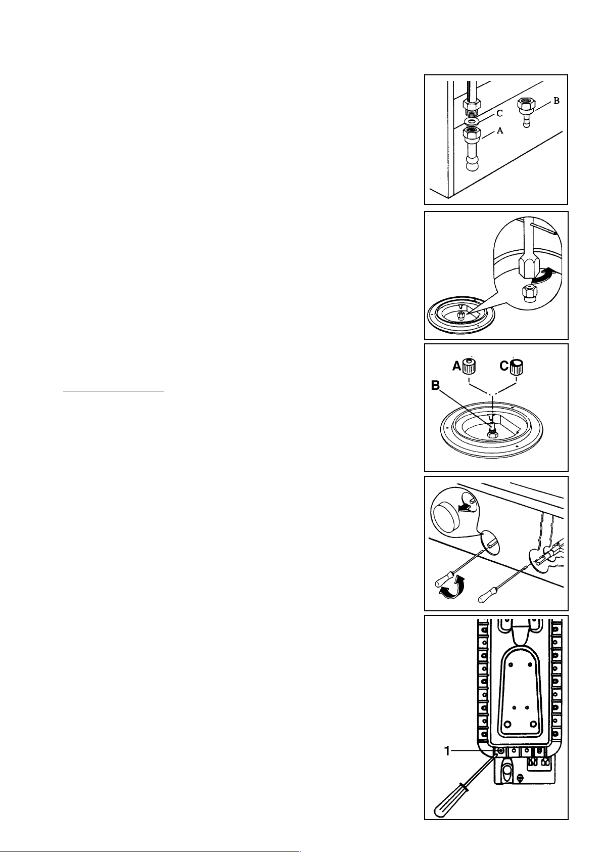
Replacement of rubber pipe holder
LPG preset range:
to set the range ready for natural gas, use rubber pipe holder
«A». (Fig. 23)
Natural gas preset range:
To set the range ready for LPG, use the rubber pipe holder
«B» (in the equipment).
Always insert the gasket «C» between the feeding pipe and
the rubber pipe holder. (Fig. 23)
Replacement of nozzles and
adjustment
Nozzle replacement:
- Remove the pan supports.
- Extract the caps and the wall baffles of the burners.
- Using a socket spanner 7 unscrew and remove (Fig. 24)
the nozzles replacing them with the ones required for the kind
of gas in use (see tables pag. 18).
Town gas (Hong Kong)
a) Auxiliary burner and semi-rapid burners: after fitting the
nozzles (Fig. 25 - lett. "B"), screw the provided grid filter "A"
(Ø 10) on them;
b) Rapid and Ultra-rapid burner burners: screw the provided
grid filter assembly "C" (Ø 16) on it.
Reassemble the parts following the same procedure
backwards.
These burners do not need any primary air regulation.
Fig. 23
Fig. 24
Fig. 25
FO 0067-B
FO 0392
FO 0465
Adjustment of minimum level of
plate burners
To adjust the minimum level:
1) turn the knob to the position of minimum flame;
2) remove the knob (Fig. 26);
3a) in case of conversion from natural gas to LPG, tightly
screw the by-pass pin of the cocks;
3b) when converting from LPG to natural gas unscrew about
one-fourth turn by-pass pin, until a regular small flame is
reached;
3c) when converting from LPG to town gas unscrew about
one turn by-pass pin, until a regular small flame is
reached.
Reassemble the parts following the same procedure
backards.
Check that, turning quickly the knob from the maximum
position to the minimum one, the flame does not go out.
Replacement of oven burner nozzle
To replace the oven nozzle, follow this procedure:
a) remove the bottom of the oven;
16
Fig. 26
Fig. 27
FO 0068
FO 1072
Page 17

b) unscrew screw 1 (Fig. 27) and take the oven burner out;
c) with a socket spanner 7 unscrew and remove the nozzle,
situated in the bottom of the oven, and replace it with the
proper one (see Technical data);
d) reassemble the burner following the same procedure
backwards.
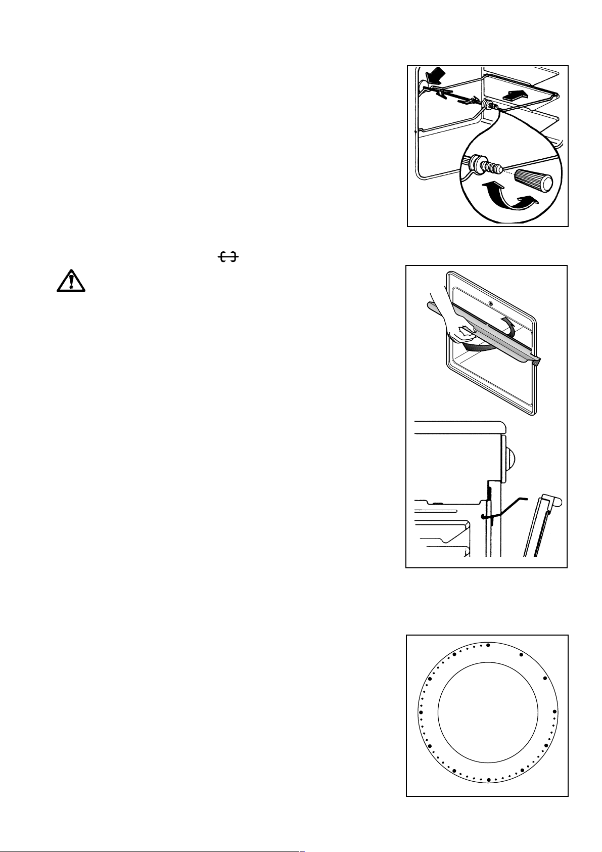
Replacement of grill burner nozzle
To replace the grill burner nozzle, act as follows:
a) remove the screws, marked with letter "A" in Fig. 28;
b) take the grill burner out;
c) with a socket spanner n. 7, unscrew and remove the
nozzle, situated in the oven top, and replace it with the
proper one (see Technical data);
d) undo the fixing screw of the metal ring of primary air
adjustment and adjust the relevant opening (see diagram);
e) reassemble the burner following the same procedure
backwards.
Minimum level adjustment of oven
burner
After setting the oven on maximum temperature with closed
door for about 10 minutes, turn the knob of the thermostat on
MIN., remove the knob and:
in case of conversion from natural gas to LPG, tightly
screw the by-pass pin of thermostat;
converting from LPG to natural gas, unscrew the by-pass
pin, until a regular small flame is reached.
The oven burner doesn't need any primary air regulation.
A
Fig. 28
Natural gas adjustment: full opening width
LPG adjustment: opening 10 mm wide
Adjustment of thermostat by-pass
pin
To reach the thermostat by-pass pin, act as follows:
- take out the knobs;
- remove the front panel;
- adjust the by-pass pin with a thin screwdriver, as shown in
Fig. 29;
- finally check that turning quickly the tap from maximum
position to minimum position, the flame does not go out;
- reassemble the front panel and the knobs.
WARNING
If the pressure of gas used is different (or variable) from that
foreseen, an appropriate pressure regulator must be installed on
the entry tube.
in case of pressure regulators for GPL are used, these must
conform to regulation.
Replacement of the gas adjustement plate
After the gas adjustment operation of the new appliance to
the new type of gas has been completed, please replace the
gas adjustment plate (located next to the connection pipe)
with the gas adjustment plate that relates to the new type of
gas being used.
The gas adjustment plate can be found in the envelope
containing the documents (e.g. the guarantee etc.).
Fig. 29
FO 1061
100
500
650
Insertion possibility
In case of insertion of the appliance between kitchen units, the
dimensions to be respected are shown in Fig. 30.
When the kitchen is installed according to class 2, sub-class
1 (i.e. built-in) for the gas connection use only flexible metallic
tubes conforming to rules in force.
Fig. 30
FO 1076
17
Page 18

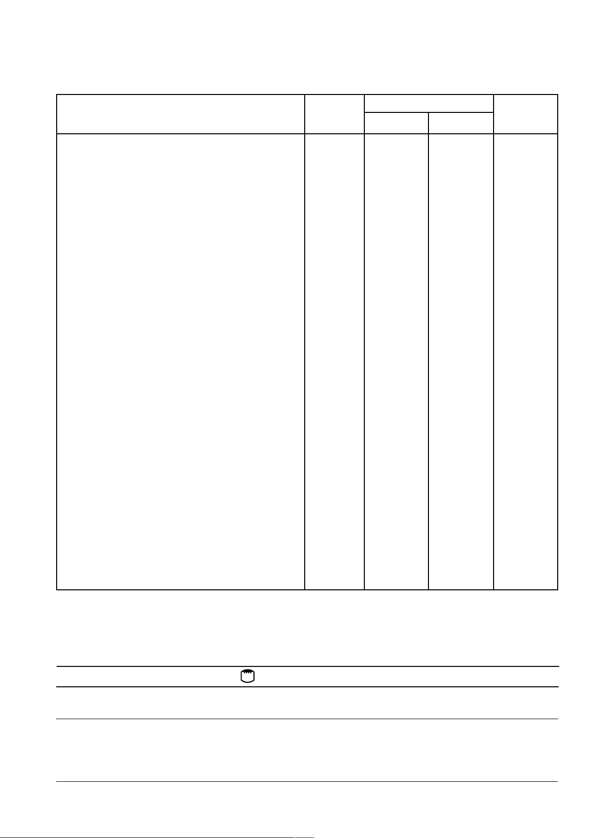
Technical data
Specifications for hob burners and injectors
TYPE BURNER INJECTORS NOMINAL REDUCED NOMINAL FEEDING
OF GAS POWER POWER POWER PRESSURE
1/100 mm kW kW m3/h g/h mbar
NATURAL
GAS
(Methane)
LIQUID
GAS
(But./Prop.)
TOWN
GAS
Triple-crown 136 3,5 1,20 0,333 -
Ultra-rapid 121 3,2 0,65 0,305 -
Rapid 119 3,0 0,65 0,286 - 20
Semi-rapid 96 2,0 0,45 0,190 -
Auxiliary 70 1,0 0,33 0,095 -
Triple-crown 93 3,5 1,20 - 252
Ultra-rapid 88 3,2 0,65 - 231
Rapid 86 2,8 0,65 - 201 28-30/37
Semi-rapid 71 2,0 0,45 - 144
Auxiliary 50 1,0 0,33 - 72
Triple-crown 235 3,2 1,20 0,666 -
Rapid 235 2,9 0,65 0,604 - 12,5
Semi-rapid 180 2,0 0,45 0,417 -
Auxiliary 134 1,1 0,33 0,229 -
Specifications for oven burners and injectors - Appliances width 90 cm
TYPE BURNER INJECTORS NOMINAL REDUCED NOMINAL FEEDING
OF GAS POWER POWER POWER PRESSURE
1/100 mm kW kW mbar
m3/h g/h
NATURAL
GAS
(Methane)
LIQUID
GAS
(But./Prop.)
Oven burner 116 3,0 1,0 0,286 - 20
Grill burner 111 2,5 - 0,238 -
Oven burner 82 3,0 1,0 - 216 28-30/37
Grill burner 74 2,3 - - 166
Specifications for oven burners and injectors - Appliances width 60 cm
TYPE BURNER INJECTORS NOMINAL REDUCED NOMINAL FEEDING
OF GAS POWER POWER POWER PRESSURE
1/100 mm kW kW m3/h g/h mbar
NATURAL
GAS
(Methane)
LIQUID
GAS
(But./Prop.)
TOWN
GAS
Plates and oven burners don't need regulation of primary air. Appliances should be installed in compliance with the local regulations.
Whereas pressure regulators are provided for appliances, they should comply with the rules in force.
Oven burner 114 2,7 1,1 0,257 - 20
Grill burner 111 2,5 - 0,238 -
Oven burner 83 2,7 1,1 - 195 28-30/37
Grill burner 80 2,5 - - 180
Oven burner 199 2,8 1,1 0,583 - 12,5
Grill burner 218 2,6 - 0,541 -
Electric Oven Heating elements rating
Model Appliances Width 60 cm Appliances Width 90 cm
Bottom heating element 1,000 W 1,200 W
Top heating element 800 W 1,000 W
Electric Grill element 1,750 W 1,800 W
Oven Light 15 W 15 W
Turnspit 4 W 4 W
Oven Capacity 57 dm³ 49,2 dm³ (appliances with electric oven)
Electric Plate: Ø 180mm - 1500 W (Mod. 65 G - 1000 W)
Appliance Class 1 and Class 2, Sub-Class 1
Category: II 2H3+
(Appliance set for use with gas: LPG G30-31 28-30/37 mbar)
Voltage tension: 230 V ~ 50 Hz
18
46 dm³ (appliances with gas oven)
Page 19

Electrical connection
The unit is preset to work with a voltage of single phase
230 V.
Before making the connection make sure that: the
energy power available in the user's house is sufficient
for the normal supply of this appliance (see rating plate).
The unit is correctly connected to earth through a
suitable plug and according to the installation country
Laws.
The socket or the omnipolar switch used for the
connection must be easilv reached with the installed
appliance. The appliance is supplied with the electric
cord: consequently, you have to install a plug fit for the
load shown in the serial number plate. The plug has to
be connected to an adequate socket.
If you wish to directly connect to the mains, you have to
interpose an omnipolar switch with a minimum opening
between contacts of 3 mm, between the unit and the
mains, complying with the existing regulations. The
brown live wire (originating from the clamp of the cooker
junction box) must always be connected to the phase
of the mains supply. In any case, the supply cord must
be positioned in such a way as it doesn't reach in any
point a temperature higher by 50°C than the room temperature.
Should the supply cord need to be replaced, it is
necessary that the yellow/green earth wire is about 2cm
longer than the live and neutral ones (Fig. 31).
After the connection, test the heating elements for about
3 minutes to ensure that they are working correctly.
The manufacturer refuses any responsability in
cases where normal safety measures are not
observed.
Fig. 31
Phase
Ground (yellow - green)
FO 0480
Neutral
wire
Something not working
If the appliance doesn't work properly check the
following points before asking for service:
The flow of gas seems abnormal
Make sure that:
the flame speader holes are not obstructed;
the pressure regulator is working;
the bottle valve is completely open.
Gas smell in the room
Make sure that:
the gas valve is not open;
the gas supply tube is well positioned and in good
condition; remember to replace it at least once a
year.
The oven doesn't heat
Make sure that the oven knobs are in the correct
working positions.
Cooking time is too long
Check that the temperature is correct for the type of
food to be cooked.
The cooker produces smoke
We advise you to clean the oven after use. Splashes
of fat can occur during the cooking of meat and, if
the oven isn't cleaned properly, these produce smoke
and bad smell. (see paragraph concerning cleaning).
The oven lamp doesn't work
The lamp has burnt out. To replace it follow the
instructions given in the relative paragraph.
If, after following all the above checks the appliance still
doesn't work, call your nearest Service Centre giving
them all the necessary information, such as model and
serial number of the appliance.
Never look for an escape of gas with a
match; use instead soap and water.
Maintenance -Technical assistance
The gas cocks must be periodically lubricated to ensure good
working and safety. Maintenance should be performed as
follows:
Remove the knob and panel after having taken out
fastening screws.
Loosen the two screws located at the sides of the cock bar.
Remove the cone and clean it carefully.
Then, apply a thin layer of grease non soluble in water,
suitable for gas cocks. Take care not to obstruct the gas
flow holes by an excess of grease.
Reassemble the whole with utmost care performing the
operations described above inversely.
Original spare parts
This machine, before leaving the factory, has been tested and
studied by many experts and specialists, in order to give you
the best results. Any repair work which needs to be carried out
should be done with the utmost care and attention. For this
reason we reccomend that for any problem you contact the
dealer who sold it to you, or our nearest authorized Service
Centre, specifying the nature of the problem and the particular
model which you own.
The guarantee
Your new cooker is covered by guarantee. You will find the
guarantee certificate enclosed. If you are missing anything,
contact your retailer, giving the date of purchase, model, and
the registration number which is printed on the identification
plate.We ask you to bear in mind that for the guarantee to be
operated, it is necessary to fill in and send the larger part of
the guarantee to Electrolux Technical Assistance & Service
within 8 days of purchase, so that we can provide registration.
We advise you that the smaller part of the certificate, as well
as your receipt and proof of purchase, should be shown when
required to personnel of Electrolux Technical Assistance &
Service. Without following this procedure, the repair personnel
will have to charge you more for the repair.
19
Page 20

The Electrolux Group. The worlds No.1 choice.
The Electrolux Group is the worlds largest producer of powered appliances for kitchen, cleaning and outdoor use. More
than 55 million Electrolux Group products (such as refrigerators, cookers, washing machines, vacuum cleaners, chain
saws and lawn mowers) are sold each year to a value of approx. USD 14 billion in more than 150 countries around the
world.
03/03
Grafiche MDM - Forlì
 Loading...