

AEG EFC9020-1X User Manual
EFC 9020X
Air purification center
Wall-mounted
With cord suspension
Installation and operating instructions
Status 03/2008
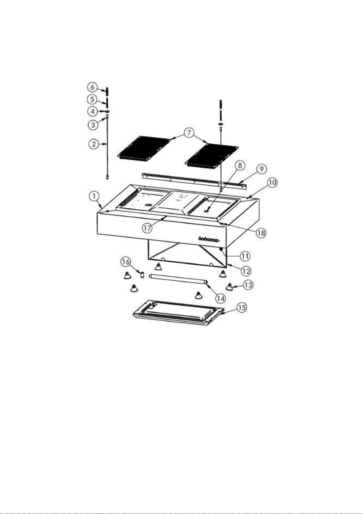
1. Hood body 10. Power cord exit
2. Cable suspension 11. Heat detector
3. Cable retainer 12. Grease collecting pan
4. Cover disc 13. Halogen lamps 20 watt EKL
5. Hanger bolt 14. Disinfection lamp (UV-C lamp) EKL
6. Dowel 15. Stainless steel/carbon filter 586 x 324 mm
7. Metal filters with ionizer sheet 16. Starter for UV-C lamp
with spring locking 17. Main switch
8. Cable for ionizer sheet 18. Retainer for cable suspension
9. Wall fixing rail
Page 2

EFA 9020X air purification center (wall-mounted) with cord suspension
Installation instructions – operating instructions
In order to utilize your exhaust hood in the best possible way, please read these instructions carefully
and keep them for later when you might need them.
1. Safety and general information
•
This exhaust hood may only be connected to a grounded socket outlet installed according to
regulations, or directly by a professional electrician. Fuse grounded socket outlet preferably direct
in the connection box. Electrical data are found inside the apparatus on the type plate after
opening the grease collecting pan (12) behind the steel filter (15). Before opening, disconnect the
device form the mains power supply by turning off main switch (17).
• Connection and putting in operation may only be carried out by a professional electrician.
• Never operate exhaust hood without filters (7/15) and/or open grease collecting pan (12).
• Always use gas cooking area appropriately.
• The flames of gas burners must always be covered by cookware. Otherwise the exhaust hood
may become damaged due to the strong generation of heat from open gas flames.
• Before commencing any cleaning or maintenance work, the power supply to the exhaust hood
must be interrupted by unplugging the connector from the socket or by switching off main switch
(17).
• Do not prepare any flambéed dishes under the exhaust hood. The open flame could cause a fire.
• Never leave the pan unattended when you deep-fry food because the grease could catch on fire.
• Constant maintenance assures unobjectionable operation and maximum performance of your
exhaust hood.
• All dirty surfaces should be regularly cleaned and cleared from deposits. The filter must frequently
be removed and cleaned.
• Wrong halogen lamps (13) may destroy the transformer.
• Do not cause the heat sensor to react by using a flame.
• Between ceiling and top of the hood a minimum distance of 300 mm must be observed.
• Minimum distance to the cooking range: with electric range: 700 mm, with gas stove: 700 mm.
• This appliance must not be used by persons, also children, with diminished psychological,
sensoric, or mental abilities, or by persons without any experience and knowledge unless they are
supervised and instructed in the use of the appliance by a person being responsible for their
safety.
• Children must never stay around unattended near the appliance and in no case play with this
device.
• Safety shutdown:
If one or more filters are removed, the appliance switches off automatically. The appliance is not
ready for use again before the filters are in place correctly.
!!! Operate this appliance only with filters (7/15) inserted and grease collecting pan (12) closed !!!
!!! Before opening this device disconnect it from the mains power supply
Do not look into the lit up disinfection radiation source (14) !!!
by turning off main switch (17) !
Do not operate appliance without filters (7/15)
(High voltage and UV-C radiation)
Page 3
2. Before mounting and installation
• The package contains the following parts: hood body including wall fixing rail, stainless steel
filters, by-pack kit, and cleaning set (the suspension cables are inside the by-pack kit)
• Verify that the exhaust hood has not been damaged during transport. Should any damage exist,
the appliance must not be installed.
• Ensure that installation and electrical connections are made by a qualified technician in
accordance with the manufacturer's specifications and official rules and regulations.
• Make sure that a 3-wire mains cable or a socket outlet is available on site. The power cord exit
(10) is located on the top at the right rear corner inside the hood body.
Caution: The electrical connection must be made by a licensed electrician. The plug connector
must remain accessible after installation. A type 12 or type 13 socket outlet is to be provided. The
length of the connecting cable is ca. 2.4 m.
3. Mounting
Caution! The connection to the 230 volt mains as well as the entire installation of this exhaust hood
1. Determine the height at which the appliance should be hung.
2. Draw an auxiliary line on the wall, which is to represent the bottom edge of the hood body.
3. Mark out the five drill points according to the hole pattern (Sketch 1) on the wall.
4. Now drill the five holes for the size 8 mm dowels.
5. Take the five size 8 mm dowels out of the by-pack kit and stick them into the drilled holes.
6. Take the wall fixing rail off from the rear side of the hood by unscrewing the three screws on the
7. Now fasten the wall fixing rail using five 5 x 50 mm round-head screws from the by-pack kit.
8. For the cable suspension you have to copy two drill holes onto the ceiling. See Sketch 2.
9. Now drill the two 10 mm holes into the ceiling.
10. Now take the two dowels and the two hanger bolts out of out of the by-pack kit and place them into
11. Thread-in the cable suspension together with the cable tightener into the hood body from the top.
12. Now hang in the hood body into the wall fixing rail.
13. Now screw the two cable suspensions together with the cable retainers onto the hanger bolts. In
14. Now turn the three screws you had unscrewed before back into the hood body.
15. By exerting pressure on the cable tensioner the cable suspension is released and the length of the
16. Connect power cord of hood to supply line on site.
17. Cover up hood after mounting so that no dirt particles can fall on the top. Do not uncover the
is unconditionally to be made at zero potential by a professional electrician.
topside of the hood.
the two holes. Screw the two cover discs from the by-pack kit onto the hanger bolts.
Screw in the cable tensioner into the retainer and lock it by tightening the headless screw. One
cable suspension per each retainer. (Figures 1 + 2).
doing so the steel cable may twist, however it will unstring again during workstep 15.
(Figure 3).
steel cable can be varied. Using a water level the hood can be leveled out. (Figure 4).
device until the kitchen is completely erected and furnished and the final cleaning has been
done.
Page 4
 Loading...