

Page 1
QUICK INSTALLATION GUIDE
Thyro-Power
Manager
EN
2
COMMISSIONING OF THYRO-POWER MANAGER
Quick Installation Guide, valid is only the actual AEG Power Solutions operating manual of
Thyro-Power Managers (No. 8.000.024.628).
CONTENTS
1. Connection for voltage supply
2. Network Load Optimization
3. Additional Measurement Device
4. Safety Notes
5. Operation
6. Contact
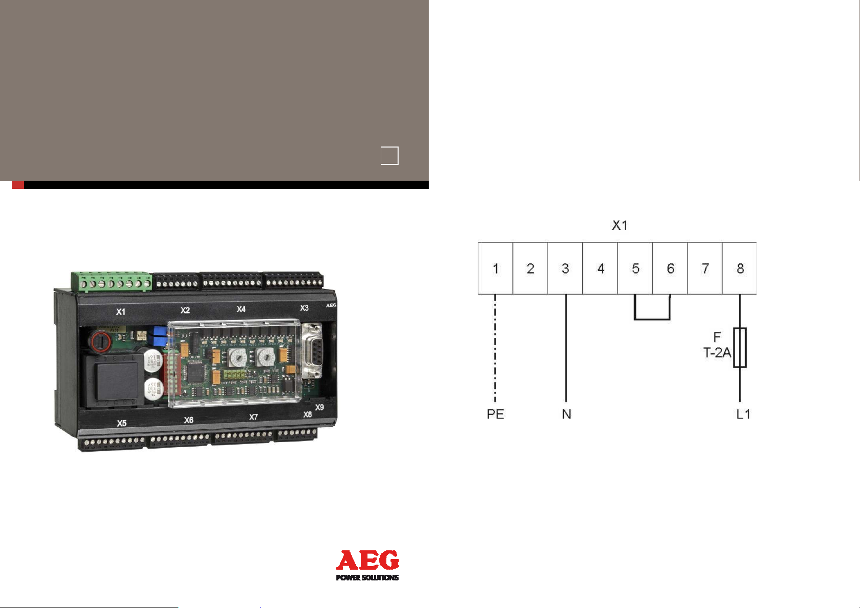
1. CONNECTION
FOR VOLTAGE SUPPLY
Figure 1: Connection diagram for voltage supply 230V~; 50/60 Hz
Page 2
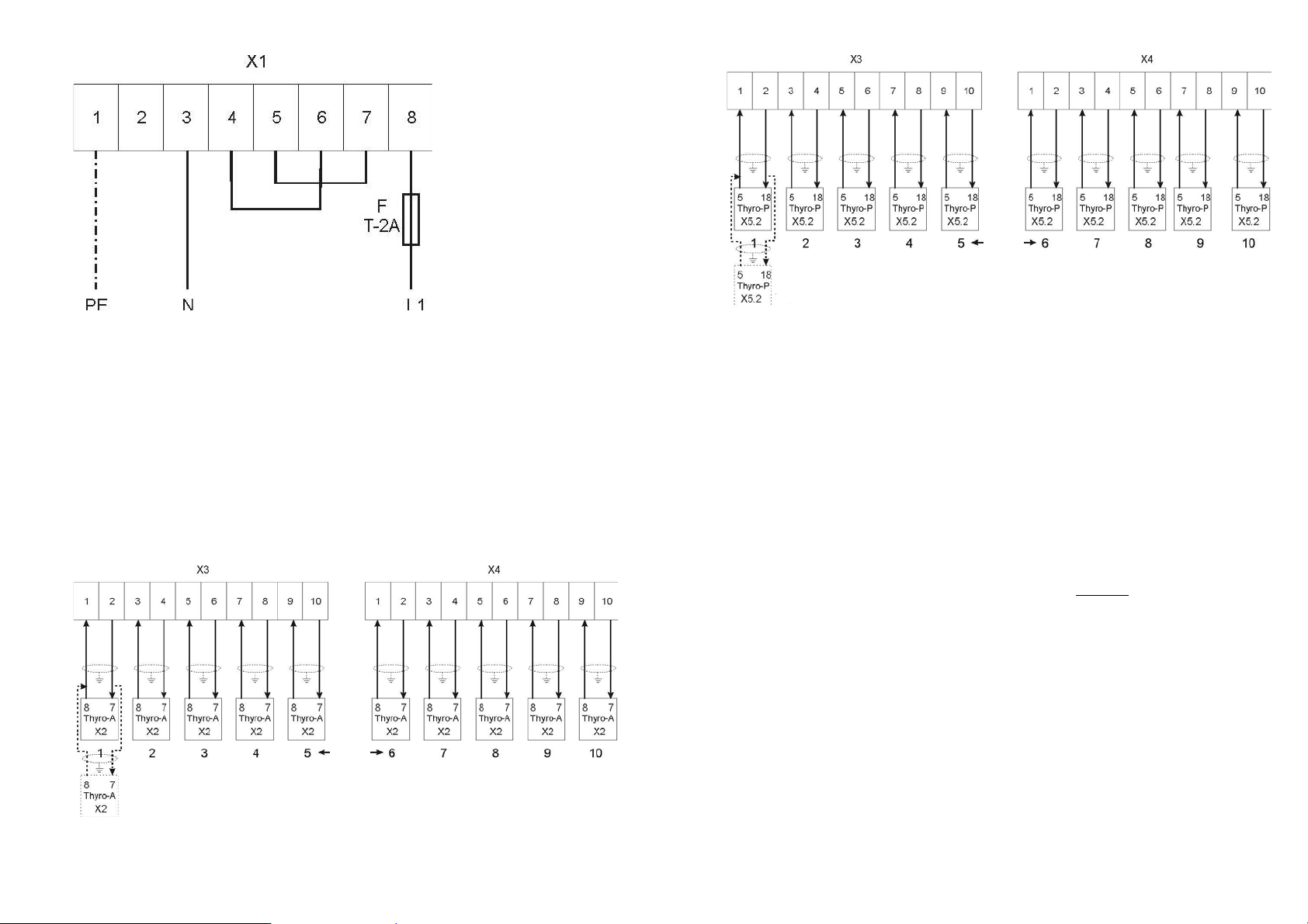
Figure 2: Connection diagram for voltage supply 110V~; 50/60 Hz
2. NETWORK LOAD OPTIMIZATION
2.1. CONNECTION FOR NETWORK LOAD OPTIMIZATION / POWER
CONTROLLER
The unit possesses 10 digital outputs at the terminals X3 and X4, in total. These are
designed as potential-free optical coupler outputs. They are deployed as
synchronization outputs (SYT) for the connected power controllers or power controller
groups during the network load optimization process. Up to 10 power controllers can be
connected per channel. To operate a 2-wire, shielded cable is required between ThyroPower Manager and each power controller.
3
4
Channel
Maybe further
Thyro-A
Figure 4: Connection Diagram for Network Load Optimization Using Thyro-P
2.2. NETWORK LOAD OPTIMIZATION SETTINGS
Setting the Operating Mode
The selected function must be set using the switch S3. Switch position 1 = automatic static
network load optimization
Setting the Number of Power Controllers
If network load optimization is used, the number of connected power controllers or power
controller groups must be set by using the switch S2. Switch position 1 = 1
controller, 2 = 2
nd
power controller etc. up to A = 10th power controller
st
power
Setting the Elementary Period Duration T0
By using the potentiometer R309 it is possible to set the elementary period duration T0. It is
default set to 50 periods = 1s ex works. Usually, this setting does not have to be
changed.
3. ADDITIONAL MEASUREMENT DEVICE
3.1. CONNECTION FOR NETWORK PEAK VALUE MONITORING /
MEASURMENTS
Channel
Maybe further
Thyro-A
Figure 3: Connection Diagram for Network Load Optimization using Thyro-A
If electrical current or voltage converters are connected to the measurement inputs (figure
5), the effective value is measured (throughout the integration time interval), and
furthermore outputted as DC signal (0 – 10V) to the three analog outputs. Additionally, the
measurement values are also internally available, and may be queried via a PC or bus
system.
Page 3

5
6
The load resistance also has to be connected externally to the current converters. Within
standard default setting the following measurement values are read out: output 1 measurement value 1, output 2 - measurement value 2, output 3 - measurement value 3.
The following figure displays the principle structure and the connection diagram if using as
additional measurement device.
Figure 5: Connection Diagram for Additional Measurement Device
3.2. SETTING THE NETWORK PEAK LOAD MONITORING /
MEASUREMENTS:
No settings are necessary for the additional measurement device. Converters or load
resistances have to be configured in a manner so that a 1V~ measurement voltage is
generated at a nominal electrical current. Thus, a voltage of 10V- results at the respective
analog output.
3.3. SETTING THE LIMITING VALUE FOR MONITORING
If the additional measurement device is also used as network peak load monitoring, limiting
value could be set via the help of the potentiometer R310. Standard setting is 200%, the
potentiometer is set on right stop, whereby 100% meaning 1V~ at the measurement inputs /
load resistances.
4. SAFETY NOTES
The commissioning of the unit is permitted only upon expert installation!
For this see the currently valid AEG Power Solutions operating manual
of Thyro-Power Manager.
5. OPERATION
5.1. REGULAR OPERATION
Enabling mains voltage during regular operation activates the unit. Subsequently, the green
power LED H100 and the green ON LED H101 should burn. If network load optimization is
used, the LEDs H201 - H210 turn ON one after another (contingent to the selected number).
All measurements and functions are performed as selected.
For more information and integration of software for programming, measurement and
indication please see our comprehensive and actual valid operations manual.
Mains voltage - Danger!
Activate the unit only if it is secured that all necessary measures for
protection against electric shock are implemented.
Page 4

6. CONTACT
TECHNICAL QUERIES
If you have any technical queries regarding the subjects dealt with in these operating
instructions, please get in touch with our team for power controllers:
Phone: +49 (0) 2902 763-520
COMMERCIAL QUERIES
If you have any commercial queries on power controllers, please get in touch with:
Phone: +49 (0) 2902 763-558
SERVICE-HOTLINE
Our team is at your service on the following hotline:
Phone: +49 (0) 2902 763-600
INTERNET
Further information about our company or products please visit:
http://www.aegps.com
6.1. COPYRIGHT
The forwarding, copying and/or receipt of this operations manual via electronic or
mechanical means, even in part, requires the expressive prior and written approval of AEG
PS.
© Copyright AEG Power Solutions GmbH 2013.
All rights reserved.
6.2. FURTHER INFORMATION ON COPYRIGHT
Thyro- is an international registered trademark of AEG Power Solutions GmbH.
All other company and product names are (registered) trademarks of the respective owners.
7
BETRIEBSANLEITUNG/ OPERATING INSTRUCTIONS
DE/EN, 08/13 – V1
Due to our policy of continuous development, the data in this document is subject to
change without notice.
AEG is a registered trademark used under license from AB Electrolux.
EMIL-SIEPMANN-STR. 32
59581 WARSTEIN-BELECKE - GERMANY
TEL.: +49 2902 763 -520/ -290 - FAX: +49 2902 763 1201
WWW.AEGPOWERCONTROLLERS.COM
 Loading...