

Page 1

155 D
Dunstabzugshaube
Cooker hood
Hotte aspirante
Cappa aspirante
Montage- und Gebrauchsanweisung
Installation and Operating Instructions
Instructions de montage et mode d’emploi
Istruzioni di montaggio ed istruzioni per l’uso
Page 2
Contents
Introduction...............................................................................23
Extractor version
Filter version................................................................................24
Electrical connections..............................................................25
Safety warnings fdt electrician
Specifications............................................................................26
.....................................................
....................................................
............,.......
25
23
Montage
Safety warnings for kitchen unit installer.....................................27
Wall unit mounting.......................................................................29
Wall mounting..............................................................................29
Safety warnings for user
Hood operation........................................................................ 31
Controls
Setting the fan speed..................................................................32
Hood lighting...............................................................................32
Intensive P
Fan timer.....................................................................................33
Switching off the fan....................................................................34
Hood operation before and after cooking
Warnings on the activated carbon filter...................................... 35
Display warning on saturation of
activated carbon filter............................................................ 35-37
Display warning on saturation of
metal grease filters
Changing the light bulbs..............................................................40
Cleaning......................................................................................40
Special Accessories
....................................................................................
.............................................................
.....................................................................................
................................................................................
....................................
................................................................
.................................................................41
38-39
27
30
31
33
35
Technical Assistance Service
22
.................................................
Printed on recycled paper.
AEG - putting words into action.
41
Page 3
Introduction
The hood is supplied as an extractor unit and can also be used
with a filtering function by fitting activated carbon filters (special
accessory).
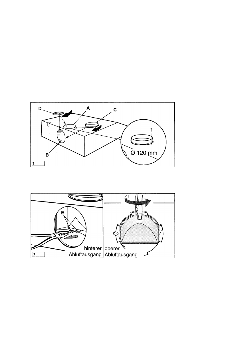
The unit features two outlet holes, one of which A is located on the
top of the unit while the other B is located on the rear.
To connect up the hose, you should first fit the bayonet-mounting
flange C on the outlet required (if using the top outlet, fix the flange
in place using the screw supplied as shown in Fig, 1.
Close off the unused hole using the bayonet-fitting caps D.
If using the rear hole, open the air passage by removing the
partition (E — Fig. 2)
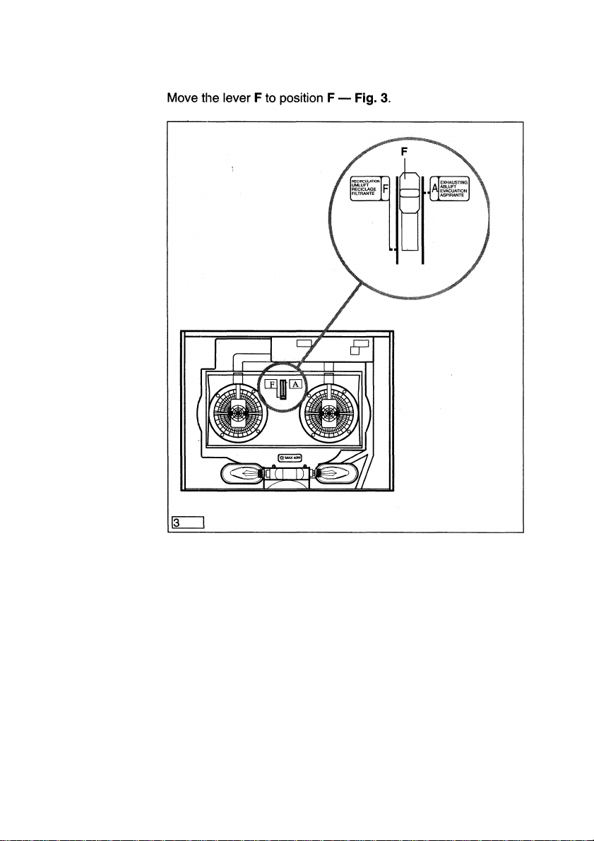
Extractor
version
Move the lever F to position A — Fig. 3.
When connecting up the hood using a telescopic wall pipe,
you should preferably using the uninflammable outlet hose
No. E 610 899 007 (120 mm 0) from our range of special
accessories.
23
Page 4
Filter
version
The air is filtered and recirculated through the front grille.
You will need an original AEG KLF60/80 activated carbon filter for
filtering function. (See special accessories).
24
Page 5

Electrical connections
Check that the power supply voltage shown on the rating plate Safety
corresponds to the mains supply before proceeding to make any warnings for
electrical connections. If the unit is supplied ready-fitted with a electrician
plug, it can be connected to any easily accessible socket installed
In compliance with the regulations In force.
If a fixed connection is required, the hood must be installed
exclusively by an electrician registered with the local electrical
company. The hood should be installed using an omnipolar switch
with contacts that open to at least 3 mm.
Fused switches can be used for this purpose (with cartridge fuses
that can be extracted from the fuse holder), as can automatic
circuit breakers and contactors which open to more than 3 mm.
We decline all responsibility for any problems or faults caused by
a failure to observe the above instructions.
Installing the socket directly above the hood or above the wall unit
mounted above the hood offers the following advantages;
1. The socket cannot be seen.
2. The unit can be disconnected whenever required by simply
taking out the plug.
Electrical connections
230 V - using fixed power supply line with plug.
(The unit should only be connected up by an authorized electri
cian).
25
Page 6

Specifications
Dimensions:
Height
152
Weight:
Net:
Gross:
Maximum absorbed power: 360 W
Motor absorption: 2 x 140 W
Lighting: 2 x 40 W
Fan powers (levels), levels in compliance with DIN 44971
Exhausting version:
min. 120 m^/h max. 254 mVh Intensive speed 385 m^/h
Recycling version:
min. 50 m^/h max. 180 m^/h Intensive speed 206 m^/h
Extractor system: 120 mm 0
10.5 Kg
11.5 Kg
Width
599
Depth (in mm)
505
26
Page 7

Montage
When used as an extractor unit, the hood must be fitted with a
120mm diameter hose.
If the outlet hose is installed In a horizontal position, it must
nevertheless be slanted at an angle of 10° so that the air can flow
outside without impediment.
If the cooking vapour Is passed through an outside wall, you will
need a telescopic wall pipe No. E 610 899 004 (120 mm o) from
our range of special accessories.
When installing the hood, make sure you respect the follow
ing minimum distance from the top edge of the cooking hob/
ring surfaces:
electric cookers
gas cookers
coal and oil cookers
The hood cannot be connected to flues of other appliances
that run on energy sources other than electricity.
It is advisable to apply for authorization from the relevant
controlling authority when connecting the outlet to an un
used chimney flue or combustion gas duct.
The air outlet installation must comply with the regulations
laid down by the relevant authorities.
650 mm
650 mm
700 mm min.
Safety
warning for
kitchen unit
installer
When the unit is used in its extractor version, a sufficiently
large ventilation hole must be provided, with dimensions that
are approximately the same as the outlet hole.
National and regional building regulations impose a number
of restrictions on using hoods and fuel-burning appliances
connected to a chimney, such as coal or oil room-heaters and
gas fires, in the same room.
The European decree on fuel-burning systems specifies a
maximum depression of 0.04 bar in such rooms.
Hoods can only be used safely with appliances connected to
a chimney if the room and/or flat (alr/environment combina
tion) is ventilated from outside using a suitable ventilation
hole approximately 500-600 cm^ large to avoid the possibility
of a depression being created during operation of the hood.
If you have any doubts, contact the relevant controlling
authority or building inspector’s office.
27
Page 8

Since the rule for rooms with fuel burning appliances is
“outlet hole of the same size as the ventilation hole”, a hole
of 500-600 cm^, which is to say a larger hole, could reduce the
performance of the extractor hood.
If the hood is used in its filtering function, it will operate
simply and safely in the above conditions without the need
for any of the aforementioned measures.
When the hood is used in its extractor function, the following
rules must be followed to obtain optimal operation:
— short and straight outlet hose
— keep bends in outlet hose to a minimum
— never install the hoses with an acute angle, they must
always follow a gentle curve only
— keep the hose as large as possible (120 mm 0).
Failure to observe these basic rules will drastically reduce
the performance and increase the noise levels of the extrac
tor hood.
28
Page 9

Drill four holes in the base of the wall unit using the template Wall unit
supplied. mounting
Mount the hood unit on the base of the wall unit using four
4,2 X 35 mm screws. -Fig.4
If using an interchangeable model, fit the plastic caps supplied in
any unused mounting holes. — Fig. 5
Position the template on the wall.
Drill four 8 mm 0 holes in the wall, 2 in points H and 2 in points I.
Fit the four 8 mm screw anchor plugs in the wall.
Screw two 5 X 45 mm screws in points H but do not tighten
them fully home.
Adjust the unit so that it is positioned at a right angle to the wall
by turning the two support screws G.
Now hang the hood on the wall (holes H). Tighten the first two
screws and, for safety’s sake, screw the other two 5 x 45 mm
screws (holes I) Into the holes in the hood. — Fig. 6
Wall
mounting
29
Page 10

Safety Never leave a cooking hob or ring on without a pot or pan on top
warnings of it, to avoid the possibility of excess heat damaging the unit. Gas,
for user oil or coal cooker flames in particular should never be left uncov
ered.
Special care should be taken when using deep fat fryers since the
oil in them can overheat and burst into flames.
The risk of a fat fire increases when using dirty oil.
It is extremely important to note that overheating can cause a fire.
Never carry out any flambé cooking under the hood.
Always disconnect the unit from the power supply before
carrying out any work on the hood, including replacing the
light bulb (take the cartridge fuse out of the fuse holder or switch
off the automatic circuit breaker).
It is very important to clean the hood and replace the filter at
the recommended intervals. Failure to do so could cause
grease deposits to build up, causing a fire hazard.
30
Page 11

Hood Operation
The control panel is located on the front of the hood.
The control panel numbers and symbols (Fig. 7 from left to right)
are explained in the key below:
= Lighting, on/off.
-d-
= Fan switch (speeds 1-9).
o
= Fan timer, 15 minutes.
: Display showing fan speed (1-9), high speed (P), change
grease filters (F) and change activated carbon filters (C).
Controls
: Decrease fan speed button for reducing speed of motor
e
e
If the hood fails to operate correctly, briefly disconnect it from the
mains power supply for almost 5 sec. by pulling out the plug. Then
plug it in again and try once more before contacting the Technical
Assistance Service.
from high speed (P) down to speed 1.
= Increase fan speed button for increasing speed of motor
from 1 to 9 and high speed (P).
31
Page 12

Setting
the fan speed
(Fig- 8)
Press the ([^) button (F) to select the fan speed from 1 to 9,
keeping it pressed until the speed you want, e.g. speed 5, is shown
on the display (D).
The red display LED (D) will come on.
If you accidentally set a higher speed than you want, press the
decrease speed button ([^) (E) until the correct speed is shown
on the display (D).
Hood lighting
(Fig- 8)
32
Simply press the ([^) button (A) to switch the lighting on or off.
Page 13

To select the intensive speed (P), press the increase speed button
([^) (F) until the letter P (high speed) is shown on the display (D).
Press the ([^) button (E) to slow down from intensive-speed
operation. The speeds 9-1 will once again be shown on the
display.
Intensive
speed P
(Fig. 9)
If there is a high level of cooking fumes or vapour, the hood should
be left In operation for at least 15 minutes after the cooker has
been completely turned off.
Press the (|^ button (C) to switch on the fan timer. I wiii
automaticaliy switch off after 15 minutes operation at the
speed you have seiected. A red dot will flash on and off on the
display (D).
Fan timer
(Fig- 9)
33
Page 14

Switching off
the fan
(Figures 10-11)
Press the key (B) to switch off the fan at any speed
including P.
After 5 seconds the number “0” (Fig. 10) will be shown on the
display (D) followed, finally, by only the red dot (Fig. 11).
34
Page 15

The hood should always be switched on before you start cooking
and left on for approximately 15 minutes after you have finished
(fan timer
Hood
operation
before and
after cooking
The activated carbon filter should be replaced at least once every
120 operating hours.
The activated carbon filter cannot be cleaned or reused.
The effective elimination of cooking odours depends on the
functional adaptation of the volume of activated carbon to the
hood’s air flow and a carefully determined position of the filter
inside the hood.
This combination inevitably decreases the air flow compared to
the extractor version.
A decisive parameter for the elimination of cooking odours is what
is known as the “residence time” of the air sucked into the hood in
the activated carbon filter.
The correct “residence time” can only be obtained using original
AEG activated carbon filters (see Special Accessories).
After 120 operating hours, the letter (C) (activated carbon filter)
will flash on and off on the display (D) in alternation with the fan
speed setting.
Warnings
on the
activated
carbon fiiter
Display
warning on
saturation of
activated
carbon filter
(Fig. 12)
This means the activated carbon filter needs to be changed!
(This operation should be carried out every 120 operating hours!)
Warning! The metal grease filters must be cleaned when you
change the activated carbon filter.
35
Page 16

Proceed as follows to remove and change my activated carbon
filter:
Switch of the fan motor by pressing the button.
Take the precaution of removing my cartridge fuses from their
fuse holder^ or tripping my automatic circuit breaker to ensure the
fan motor cannot be switched on accidentally.
1. Remove the grille (Fig. 13).
— Open my latch L and swing the grille downwards.
— To remove the grille, pull it forwards from the right and
release it.
36
Page 17

2. The activated carbon filter should under absolutely no circum
stances ever be washed. To remove it, press the two red
buttons B and pull it down and out (Fig. 14).
3. Clean the Inner housing using a hot detergent solution only
(never use caustic detergents, abrasive powders or brushes).
4. Fit the new activated carbon filter in its special frame. Inserting
the back end first and then pushing the front into place before
finally locking it into position using the lock devices (red
buttons. Fig. 14, B) on the activated carbon filter (Fig. 14, C).
6. Proceed as follows to reset the filter saturation display (coun
ter). Select any fan speed using my E or F buttons and
then press the B and F buttons at the same time,
continuing to hold them down for at least 3 seconds until the
flashing letter C stops being shown on the display (D) and then
press the button B.
The activated carbon filter display Is now ready for use again.
37
Page 18

Display
warning on
saturation
of metal
grease filter
(Fig. 15)
After 30 operating hours the letter (F- grease filters) will flash on
and off on the display (D) in alternation with the fan speed setting.
This means that the metal grease filters need to be cleaned!
(This operation should be carried out every 30 operating hours!)
Proceed as follows to remove and clean the metal filters:
Switch of the fan motor by pressing the button.
Take the precaution of removing my cartridge fuses from their
fuse holders or tripping the automatic circuit breaker to ensure the
fan motor cannot be switched on accidentally.
1. Remove the grille (Fig. 16).
— Open my latch L and swing the grille downwards.
— To remove the grille, pull it forwards from the right and
release it.
Remove the metal filter by operating the stops that fix them to the
grille.
38
Page 19

2. Clean the inner housing using a hot detergent solution only
(never use caustic detergents, abrasive powders or brushes).
3. Leave the metal grease filter panel to soak for approximately 1
hour in very hot water with grease-dissolving detergent and
then rinse it with very hot water. Repeat the operation if
necessary. Load the grease filter panel in a dishwasher,
selecting the most intensive washing programme and maxi
mum temperature, at least 65°C. Repeat the operation if
necessary.
4. When both metal grease filters have been cleaned and left to
dry, replace them by following the above operations in reverse
order (front first and then back).
5. Screw the fuses back in or reset the automatic circuit breaker.
6. Proceed as follows to reset the filter saturation display (coun
ter). Select any fan speed using my E or F buttons and
then press my [q] B and F buttons at the same time,
continuing to hold them down for at least 3 seconds until the
flashing letter F stops being shown on the display (D) and then
press the button B.
39
Page 20

Changing — Disconnect the unit from the mains power supply,
the light — Remove my cover
bulbs — Replace the old light bulb with a new light bulb (40 W max.).
— If the light does not come on, make sure the bulb has been
screwed in correctly before contacting the technical assist
ance service.
Cleaning Warning: always disconnect the hood from the mains power
supply before cleaning it.
Never insert pointed objects in the motor’s protective grille.
Wash the outside surfaces using a delicate detergent solution.
Never use caustic detergents or abrasive brushes or powders.
Only ever clean the switch panel and filter grille using a damp cloth
and delicate detergents.
Attention!
Attention! Failure to observe the instructions on cleaning the unit
and changing the filters will cause a fire hazard. You are therefore
strongly recommended to follow these instructions.
40
Page 21

MKZ telescopic wall pipe
120 mm outlet hose
KLF60/80 activated carbon filter
E-Nr. 610 899 004
610 899 007
610 899 421
Technical assistance service
You are welcome to telephone our technical assistance service
(see list of technical assistance centres) whenever you need
information or in the unlikely event of a fault.
When calling, please be ready to specify;
1. The model code number
2. The E-Nr.
3. The F-Nr.
This information is shown on the registration plate inside the unit behind the grease filter grille.
We reserve the right to change specifications and colours as a
result of our policy of continuing technological development.
41
Page 22

AEG
Bitte geben Sie unserem Kundendienst folgende Angaben
bei einer Störung an:
If your appliance has a fault, please contact our service
engineer and state the following numbers:
Veuillez donner les indications suivantes à notre service
après-vente en cas de panne:
In caso di difetto vi preghiamo di comunicare al servizio
tecnico assistenza clienti i seguenti dati:
E-Nr. 610
F-Nr.
AEG Hausgeräte AG
Postfach 1036
D-90327 Nürnberg
© Copyright by AEG
H 260 264 900
L 437B Ed. 06/95 :
 Loading...