

Page 1
$30.00
Operation and Installation Manual
WDMR and WDFR Series
Dehumidifying Dryers
Important! Read Carefully Before Attempting to Install or Operate Equipment
WD Series
Dehumidifying Dryer
Process
HI-Process
Heater on
Process Delivery
Process Delivery
Air Temp
Temperature
Temperature
ON
Left Bed
Righp Bed
Heater
Heater
888
Left Bed
Right Bed
OFF
In Regen
In Regen
Process Dew Point
-
20
15
10
25-
-
-
30
5
3540-
0
-
High Dew Point
DEW POINT (F)
WD Series
Dehumidifying Dryer
Process
HI-Process
Heater on
Process Delivery
Process Delivery
Temperature
Temperature
888
3540-
-
Part No. A0547682 Bulletin No. WH1-615
Air Temp
ON
Righp Bed
Left Bed
Heater
Heater
Left Bed
Right Bed
OFF
In Regen
In Regen
Process Dew Point
-
20
15
10
25-
-
-
30
5
0
High Dew Point
DEW POINT (F)
Page 2

Page 3

Performance figures stated in this manual are based on a standard atmosphere of 59°F
(15°C) at 29.92” Hg (1,014 millibars) at sea level, using 60 hz power. Altitude is an
important consideration when specifying dehumidifying dryers. AEC/Whitlock can advise
you on proper selection and sizing of systems for your operating environment.
AEC/Whitlock is committed to a continuing program of product improvement.
Specifications, appearance, and dimensions described in this manual
are subject to change without notice.
© Copyright AEC/Whitlock and AEC, Inc. 2004
All rights reserved. Effective 7/23/2004
Part No. A0547682 Bulletin No. WH1-615.2
Page 2 WDMR and WDFR Series Dehumidifying Dryers
Page 4

Safety Considerations
AEC/Whitlock WDMR and WDFR Series dehumidifying dryers are designed to provide safe
and reliable operation when installed and operated within design specifications, following
national and local safety codes.
To avoid possible personnel injury or equipment damage when installing, operating, or
maintaining this equipment, use good judgment and follow these safe practices:
Follow all SAFETY CODES.
Wear SAFETY GLASSES and WORK GLOVES.
Disconnect and/or lock out power before servicing or maintaining the dryer.
Use care when LOADING, UNLOADING, RIGGING, or MOVING this equipment.
Operate this equipment within design specifications.
OPEN, TAG, and LOCK ALL DISCONNECTS before working on this equipment. It is a
good idea to remove the fuses and carry them with you
Make sure the dryer and components are properly GROUNDED before switching on power.
Do not jump or bypass any electrical safety control.
Do not restore power until all tools, test equipment, etc. have been removed and the dryer
and allied equipment are fully reassembled.
Only PROPERLY TRAINED personnel familiar with the information within this manual
should work on this equipment.
WDMR and WDFR Series Dehumidifying Dryers Page 3
Page 5

Table of Contents
1 General Information .................................................7
1-1 Models Covered
1-2 Equipment Function
1-3 Necessary Documents
1-4 Standard Features
1-5 Options
1-6 The Closed Loop Drying System
1-7 What is Desiccant?
1-8 The Process/Regeneration Cycle
1-9 Specifying a Drying System
2 Shipping Information..............................................13
2-1 Unpacking and Inspection
2-2 In the Event of Shipping Damages
2-3 If the Shipment is Not Complete
2-4 If the Shipment is Not Correct
2-5 Returns
3 Installation............................................................... 15
3-1 Work Rules
3-2 Rigging and Placing the Dryer
3-3 Making Electrical Connections
3-4 Checking for Proper Blower Rotation
3-5 Making Dryer/Drying Hopper Process Air Connections
3-6 Drying Hopper Air Trap Considerations
3-7 Installing the Optional Aftercooler
4 Level 1 Controllers .................................................25
4-1 Level 1 Control Panel Indicator Lights
4-2 Level 1 Switches and Meters
4-3 Level 1 PLC Controller
4-4 Level 1 Process Air Temperature Controller
4-5 Level 1 PLC LED Indicators
4-6 Level 1 Temperature Controller LED Indicators
4-7 Level 1 Temperature Controller Keys
Page 4 WDMR and WDFR Series Dehumidifying Dryers
Page 6

Table of Contents
5 Additional Level 2 Controller Features................. 33
5-1 Level 2 Control Panel
5-2 Level 2 Control Panel Indicator Lights
5-3 Level 2 Switches and Meters
5-4 Level 2 PLC Controller
5-5 Level 2 Process Air Temperature Controller
5-6 Level 2 Temperature Controller LED Indicators
5-7 Level 2 PLC LED Indicators
5-8 Level 2 Temperature Controller Keys
5-9 Level 2 Optional Communications Protocols
6 Startup, Shutdown, and Operation .......................41
6-1 Pre-Startup Checks
6-2 Startup
6-3 Shutdown
6-4 Setting the Process Air Temperature
6-5 Setting the High Temperature Alarm
6-6 Temperature Controller Internal Switches
6-7 Enabling the Temperature Controller Anti-Tamper Lockout Switch
6-8 Changing the Display from Fahrenheit to Celsius
7 Maintenance ............................................................ 47
7-1 Work Rules
7-2 Servicing Process Air Filters
7-3 Servicing the Dew Point Monitor
7-4 Symptoms of Worn Desiccant
7-5 Replacing Worn Desiccant
7-6 Replacing the Process Heater
7-7 Replacing the Regeneration Heater
7-8 Restoring the Temperature Controller to Factory Setup
7-9 Error Display and Output
7-10 Maintaining the Aftercooler
7-11 Entering Level 2 Controller Parameters/Advanced Topics
8 Troubleshooting ..................................................... 71
WDMR and WDFR Series Dehumidifying Dryers Page 5
Page 7
Charts and Figures
1
Typical Air Flow Schematic 9
2
WD10MR to WD50MR Dryer Specifications 10
3
WDMR Series Machine-Mount Dimensions 10
4
WDFR Series Floor-Mount Dimensions 11
5
Suggested Lift Rigging for WDMR and WDFR Dryers 16
6
Typical WD10MR/FR Electrical Schematic, Drawings 1 and 2 18, 19
7
Typical WD25MR/FR, WD50 MR/FR Electrical Schematic, Drawings 1 and 2 20, 21
8
Typical Control Subpanel Layout 22
9
Aftercooler Design Specifications 24
10
11
12
13
14
15
16
17
18
19
20
21
22
Typical Enclosure with Level 1 Control Panel, Optional Dew Point System, Disconnect 26
Level 1 Process Air Temperature Control Graphic Layout 27
Level 1 PLC Controller Details 30
Optional Level 2 Controller 34
Level 2 PLC Controller Details 37
Required Desiccant Amounts per Bed 52
Level 1 Controller Factory Preset Parameters 56
Level 2 Controller Factory Preset Parameters 59
Level 1 Controller Error Messages 60
Level 2 Process Temperature Controller Error Messages 66
Optional 7-Day Timer 66
Optional WD50MR/FR Aftercooler Spare Parts List 74
WD10MR and WD10FR Spare Parts List 75
23
24
Page 6 WDMR and WDFR Series Dehumidifying Dryers
WD25MR and WD25FR Spare Parts List 76
WD50MR and WD50FR Spare Parts List 77
Page 8

1 General Information
1-1 Models Covered
This manual provides instructions for installing and operating AEC/Whitlock WD10MR,
WD25MR, and WD50MR dehumidifying dryers. Models designated with
configurations and models designated with
represents air flow capacity. WD10 models have a 10 cfm (17 cmh) air flow capacity, WD25
models have a 25 cfm (42 cmh) air flow capacity, and WD50 models have a 50 cfm (85 cmh)
capacity.
F are floor-mount models. The number designation
1-2 Equipment Function
Whitlock dehumidifying dryers are designed to generate heated, dehumidified air at carefully
controlled temperatures for use in closed-loop plastic drying systems. Drying systems are sized
to meet the specific requirements stated by the purchaser at the time of purchase.
Moisture removal from hygroscopic (moisture attracting) plastic pellets is an essential step in the
manufacture of high-quality plastic products.
AEC/Whitlock dehumidifying dryers are used to generate very low dew point air heated to a
controlled temperature for drying plastic pellets and regrind.
M are machine-mount
1-3 Necessary Documents
The documents listed below are necessary for the operation, installation, and maintenance of
AEC/Whitlock WD10MR/FR through WD50MR/FR dryers. Additional copies are available
from AEC, Inc. Familiarize the appropriate personnel with these documents:
This manual.
The schematic and assembly drawings included in the customer information packet.
The Customer Parts List included in the information packet.
Operation and installation manuals for any optional controls or auxiliary equipment in the
drying system.
WDMR and WDFR Series Dehumidifying Dryers Page 7
Page 9

1-4 Standard Features
Dual desiccant beds
Electric air control valve
13X desiccant
Up to 400ºF (204ºC) drying temperature range
1-5 Options
Options can tailor your AEC/Whitlock dehumidifying dryer to meet the exact requirements of
the drying task being performed.
Dew point monitor indicates dryer efficiency.
Electrical disconnect.
Seven day timer to allow programmable dryer startup.
Communications to meet customer needs.
Drying hoppers come in many sizes and mounting configurations.
Conveying equipment to transport material to and from the drying system.
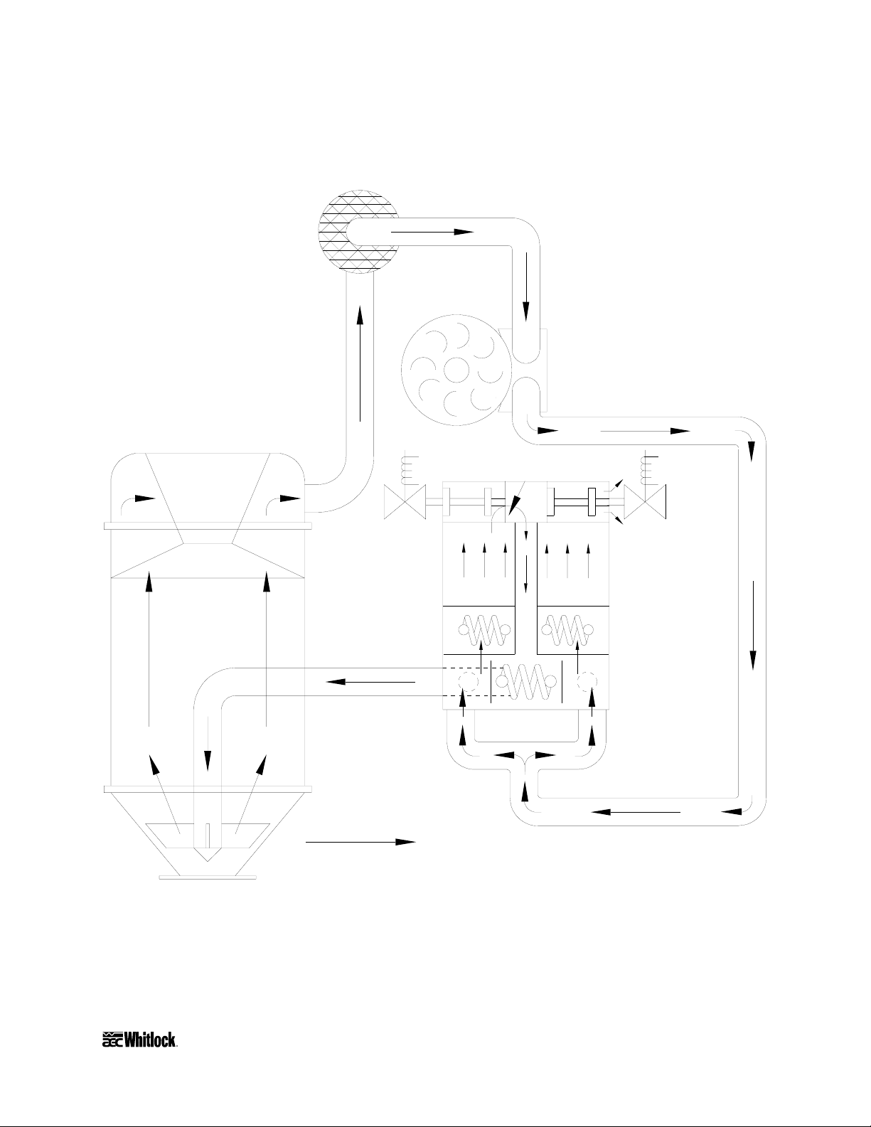
1-6 The Closed Loop Drying System
AEC/Whitlock dryers force hot, dry air through the resin in the drying hopper, where the air
picks up moisture from the material and is drawn back to the dryer.
In the dryer, a desiccant bed strips moisture from the air. The dried process air is then re-heated
and delivered back into the drying hopper to dry material again.
This system is a closed loop, because ambient (outside) air is never introduced into the process
air. AEC/Whitlock uses the closed loop system because the process air is typically much drier
than ambient air, even after carrying moisture out of the plastic resin. Recycling process air
maintains drying efficiency at a consistently high level.
Page 8 WDMR and WDFR Series Dehumidifying Dryers
Page 10
P
Drying
hopper
Figure 1
Typical Air Flow Schematic
rocess
filter
Regeneration &
process
blower
Bed
shift
valve
Desiccant
bed
Left
regeneration
heater
Arrows represent air flow
Bed
shift
valve
Desiccant
bed
Right
regeneration
heater
Process
heater
WDMR and WDFR Series Dehumidifying Dryers Page 9
Page 11
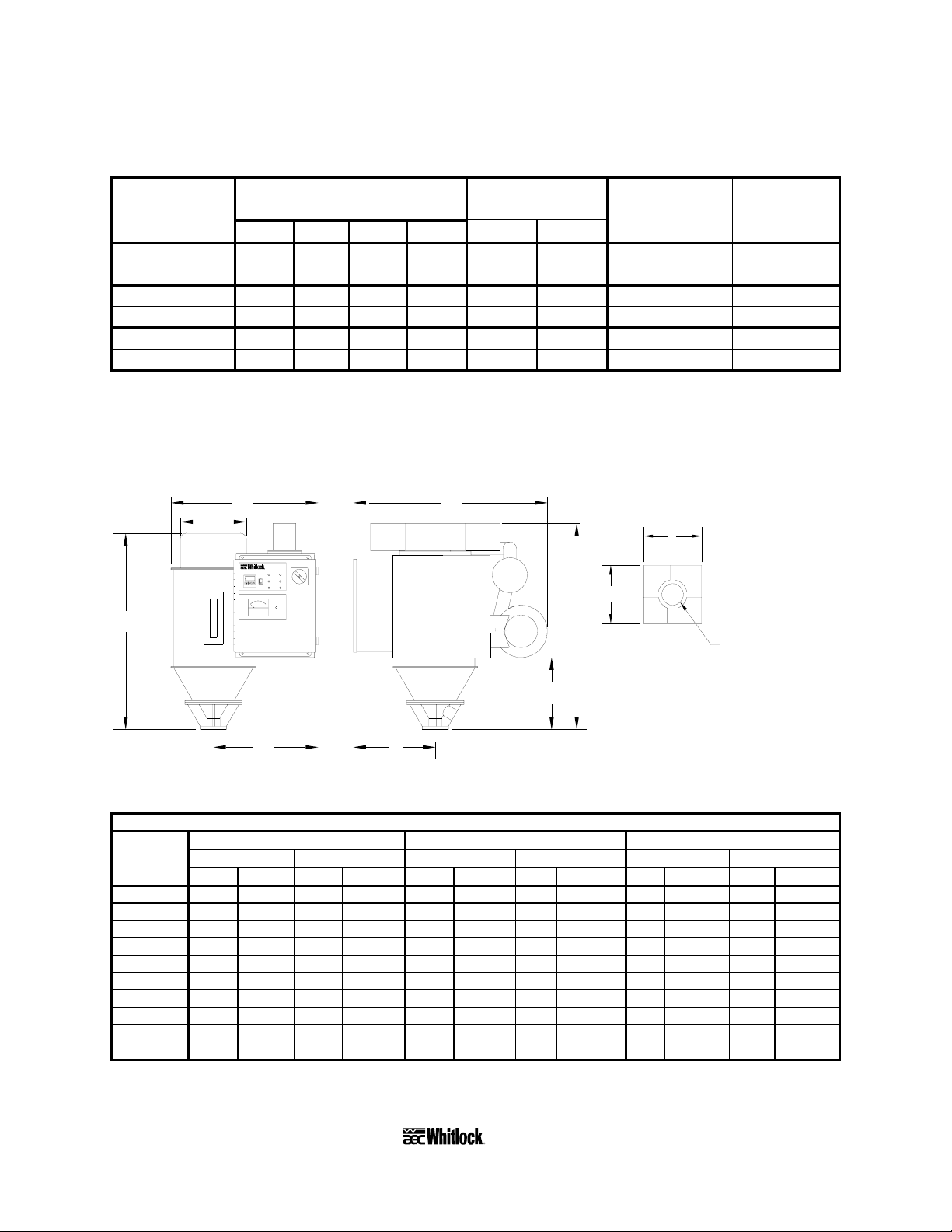
Figure 2
A
WD10MR through WD50MR Dryer Specifications
Hopper Process Full
Model size air flow Standard load
number cu. ft. liters lbs. Kg cfm cmh voltage amps
WD10MR 0.7 20 25 11.3 10 17 115/1/60 20.8
WD10MR 1.5 40 50 22.7 10 17 115/1/60 20.8
WD25MR 1.5 40 50 22.7 25 42 460/3/60 10.8
WD25MR 3.0 80 100 45.4 25 42 460/3/60 10.8
WD50MR 4.0 120 150 68.1 50 85 460/3/60 19.0
WD50MR 6.0 160 200 90.8 50 85 460/3/60 19.0
At high temperature operation.
Figure 3
WDMR Series Machine-Mount Dimensions
E
B
Process
HI-Process
Heater on
Process Delivery
Process Delivery
Air Temp
Temperature
Temperature
ON
Left Bed
Righp Bed
Heater
Heater
888
Left Bed
Right Bed
OFF
In Regen
In Regen
Process Dew Point
-
15
20
10
25-
-
-
30
5
3540-
0
-
High Dew Point
DEW POINT (F)
C
F
G
D
H
Mounting flange
J
J
Diameter hole:
K
Hopper mounting flanges on 0.75 and
Notes:
and 1.5 cu. ft. (20 & 40 liter) hoppers
are supplied blank so the customer
can drill to match existing machine throat.
3.0 cu. ft. (80 liter) hoppers and larger
are not supplied with a cast flange
(as shown).
Front Side
WD10MR, WD25MR, WD50MR machine-mount dimensions in inches/cm
WD10MR WD25MR WD50MR
.7 ft.3/20 liters 1.5 ft.3/40 liters 1.5 ft.3/40 liters 3.0 ft.3/80 liters 4.0 ft.3/120 liters 6.0 ft.3/160 liters
Dimension in. cm in. cm in. cm in. cm in. cm in. cm
A 24´´ 61.0 cm 27´´ 68.6 cm 29´´ 73.7 cm 385/8´´ 98.1 cm 38´´ 96.6 cm 38´´ 96.6 cm
B 101/8´´ 25.7 cm 141/8´´ 35.9 cm 141/8´´ 35.9 cm 20´´ 50.8 cm 20´´ 50.8 cm 20´´ 50.8 cm
C 31´´ 78.7 cm 351/2´´ 90.2 cm 351/2´´ 90.2 cm 38´´ 96.6 cm 45´´ 114.3 cm 56´´ 142.3 cm
D 18´´ 45.7 cm 163/4´´ 42.6 cm 21´´ 53.3 cm 251/2´´ 64.8 cm 26´´ 66.1 cm 26´´ 66.1 cm
E 301/2´´ 77.5 cm 301/2´´ 77.5 cm 34´´ 86.3 cm 34´´ 86.3 cm 40´´ 101.6 cm 40´´ 101.6 cm
F 343/4´´ 88.3 cm 361/2´´ 92.7 cm 393/4´´ 101.0 cm 447/8´´ 114.0 cm 51´´ 129.6 cm 51´´ 129.6 cm
G 101/2´´ 26.7 cm 143/4´´ 37.5 cm 15´´ 38.1 cm 17´´ 43.2 cm 17´´ 43.2 cm 17´´ 43.2 cm
H 14´´ 35.6 cm 121/2´´ 31.8 cm 15´´ 38.1 cm 15´´ 38.1 cm 18´´ 45.7 cm 18´´ 45.7 cm
J 4´´ 10.2 cm 4´´ 10.2 cm 4´´ 10.2 cm 7´´ 17.8 cm 7´´ 17.8 cm 7´´ 17.8 cm
K 11/2´´ 3.8 cm 11/2´´ 3.8 cm 11/2´´ 3.8 cm 2´´ 5.1 cm 2´´ 5.1 cm 2´´ 5.1 cm
Page 10 WDMR and WDFR Series Dehumidifying Dryers
Page 12
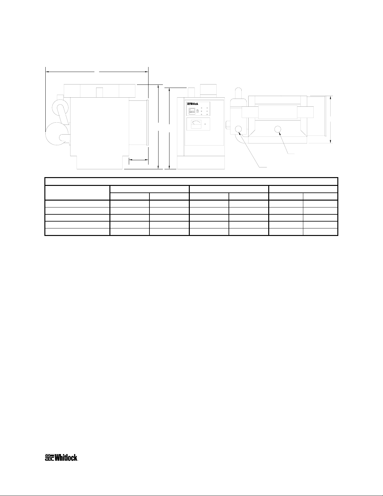
Figure 4
r
WDFR Series Floor-Mount Dimensions
B
Process
HI-Process
Heater on
Air Temp
Process Delivery
Process Delivery
Temperature
Temperature
ON
Left Bed
Righp Bed
Heater
Heater
888
Left Bed
Right Bed
OFF
In Regen
In Regen
Process Dew Point
-
20
15
10
25-
-
-
30
5
3540-
0
-
High Dew Point
C
D
DEW POINT (F)
2" OD (about 51 mm)
FMASSY
6"
15.2 cm
2" OD (about 51 mm)
return from hoppe
delivery to hopper
WD10FR, WD25FR, WD50FR floor-mount dimensions in inches/cm
WD10FR WD25FR WD50FR
Dimension in. cm in. cm in. cm
A 121/2 31.8 121/2 31.8 14 35.6
B 321/2 82.6 33 83.8 41 104.2
C 241/2 62.2 27 68.6 34 86.3
D 23 58.4 25 63.5 32 81.3
E 16 40.6 18 45.7 18 45.7
A
1-7 What is Desiccant?
Desiccant is a material that attracts and holds (absorbs) water from the air. The desiccant
AEC/Whitlock dryers use is a synthetic crystalline metal aluminosilicate blended with a clay
binder and formed into beads.
Absorbed water is driven from saturated desiccant by heating it to a high temperature (reducing
desiccant capacity to hold water) and forcing air through it. This moisture removal process is
called regeneration.
1-8 The Process/Regeneration Cycle
AEC/Whitlock WDMR and WDFR dryers have two desiccant beds. While one bed is on-line in
the process air loop, the other is off-line, being regenerated.
When a desiccant bed is on-line, it absorbs moisture from the process air. In time, the bed
becomes saturated with moisture and needs to be regenerated. The dryer automatically redirects
the process airflow to the second bed, and starts the regeneration cycle on the first bed.
WDMR and WDFR Series Dehumidifying Dryers Page 11
Page 13

During regeneration, the dryer system heats air and forces it through the desiccant bed. The
moisture driven off the bed bleeds to the atmosphere.
If you measure the temperature of the air bled to the atmosphere (bleed temperature), you should
observe a rise after a period of time. This condition, called bed breakthrough, indicates that the
bed is dry. At bed breakthrough, the bleed air temperature peaks at approximately 400°F
(204ºC).
1-9 Specifying a Drying System
Many variables were considered in the selection of your drying system, including type of
materials, residence time, throughput of the extruder or injection molding machine,
ambient air moisture and temperature, and the altitude at the processing site. Should your
operating environment change, AEC/Whitlock can advise you on necessary equipment and
process time and temperature modifications required for your system.
Page 12 WDMR and WDFR Series Dehumidifying Dryers
Page 14
2 Shipping Information
2-1 Unpacking and Inspection
You should inspect your Whitlock dehumidifying dryer for possible shipping damage. If the
container and packing materials are in re-usable condition, save them for reshipment, if
necessary.
Thoroughly check the equipment for any damage that might have occurred in transit, such as
broken or loose wiring and components, loose hardware and mounting screws, etc. In case of
breakage, damage, shortage, or incorrect shipment, refer to the following sections.
2-2 In the Event of Shipping Damages
Important!
According to the contract terms and conditions of the Carrier,
the responsibility of the Shipper ends at the time and place of shipment.
The Carrier then assumes full responsibility of the shipment.
Notify the transportation company’s local agent if you discover damage.
Hold the damaged goods and packing material for the examining agent’s inspection. Do not
return any goods to AEC, Inc. before the transportation company inspection and
authorization.
File a claim against the transportation company. Substantiate the claim by referring to the
agent’s report. A certified copy of our invoice is available upon request. The original Bill of
Lading is attached to our original invoice. If the shipment was prepaid, write us for a
receipted transportation bill.
Advise AEC, Inc. regarding your wish for replacement and to obtain an RMA (return
material authorization) number.
WDMR and WDFR Series Dehumidifying Dryers Page 13
Page 15

2-3 If the Shipment is Not Complete
Check the packing list. The apparent shortage may be intentional. Back-ordered items are noted
on the packing list. You should have:
WDMR or WDFR Series dryer
Bill of lading
Packing list
Operating and Installation packet
Electrical schematic and panel layout drawings
Component instruction manuals
Re-inspect the container and packing material to see if you missed any smaller items during
unpacking. Determine that the item was not inadvertently taken from the area before you
checked in the shipment. Notify AEC, Inc. immediately of the shortage.
2-4 If the Shipment is Not Correct
If the shipment is not what you ordered, contact AEC, Inc. immediately. Include the order
number and item. Hold the items until you receive shipping instructions.
2-5 Returns
Important!
Do not return any damaged or incorrect items
until you receive shipping instructions from AEC, Inc.
Page 14 WDMR and WDFR Series Dehumidifying Dryers
Page 16

3 Installation
3-1 Work Rules
The installation, operation, and maintenance of this equipment must be conducted in accordance
with all applicable work and safety codes for the installation location. This may include, but is
not limited to, OSHA, NEC, CSA, and any other local, national, and international regulations.
• Read and follow these operating instructions when installing, operating, and maintaining
this equipment. If the instructions become damaged or unreadable, you can obtain
additional copies from AEC/Whitlock.
• Only qualified personnel familiar with this equipment should work on or with this dryer.
• Work with approved tools and devices.
• Disconnect the electricity before maintenance or service. If the dryer is installed with a
power cord that can be unplugged, unplug it. If the dryer is permanently wired to a power
main, you must install a fused power disconnect to allow the disconnect to be locked in the
OFF position. Open and lock out the disconnect installed in the control enclosure.
3-2 Rigging and Placing the Dryer
Take care when rigging and placing the dryer. Figure 5 on the following page shows a suggested
safe rigging diagram. It lets you lift the dryer/hopper unit vertically for installation on the
machine throat. Adjust chain lengths at the center sling bracket before you lift the unit. Your
dryer has built-in lifting lugs.
Caution!
Use caution and observe safety rules when lifting and placing your dryer!
Note: Due to the large physical size of WD50MR dryer units, extra customer-provided support
is required to stabilize these units and to protect personnel when installing on machine
throats.
WDMR and WDFR Series Dehumidifying Dryers Page 15
Page 17
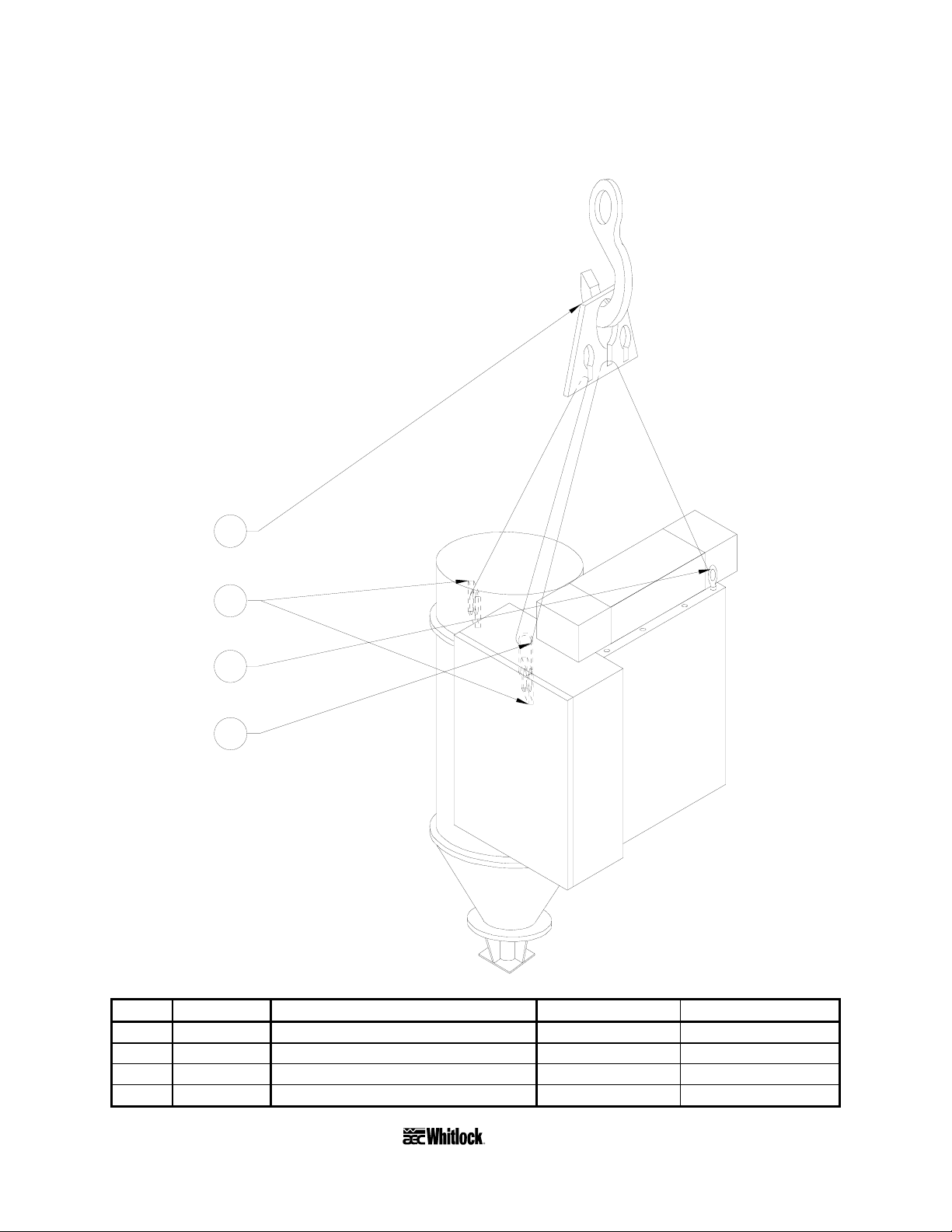
Figure 5
Suggested Lift Rigging for WDMR and WDFR Dryers
1
2
3
4
A0552486
Item Quantity Description Vendor Vendor part no.
1 1 Adjustable alloy chain sling McMaster-Carr 33665T32
2 2 Existing hopper lifting bracket — —
3 1 Drop forged steel eye nut McMaster-Carr 3019T15
4 1 Chain connector McMaster-Carr 3712T23
Page 16 WDMR and WDFR Series Dehumidifying Dryers
Page 18

3-3 Making Electrical Connections
The serial tag lists voltage, phase, and amp draw information.
Line voltage must be within plus or minus ten percent (±10%) of the voltage listed on the
serial tag, or damage may occur. Phase imbalance must be less than two percent (2%).
Fulfill all national, state, and local safety and electrical code requirements.
A qualified electrician should make all electrical connections.
Make sure all electrical connections are tight.
Connect main power to the dryer at the disconnect or terminals in the upper right corner of
the control enclosure.
Install a fused disconnect with a lockout feature in the power main leading to the dryer.
The power drop must include a ground wire.
3-4 Checking for Proper Blower Rotation
Three-Phase Models
The blower rotates properly when air flows from the delivery outlet.
Caution!
In three-phase models, incorrect phasing of power leads
can cause backward rotation of blower motors
and CONTAMINATION OF THE DESICCANT!
Always check blower rotation before putting material in the drying hopper!
If the three-phase blower rotates improperly, reverse any two wires at the fused disconnect
outside the dryer or at the disconnect/terminal in the control enclosure. This assures that the
blower rotates in the proper direction.
WDMR and WDFR Series Dehumidifying Dryers Page 17
Page 19
L1
L2
OPTIONAL
DISCONNECT
1DISC
115/60/1
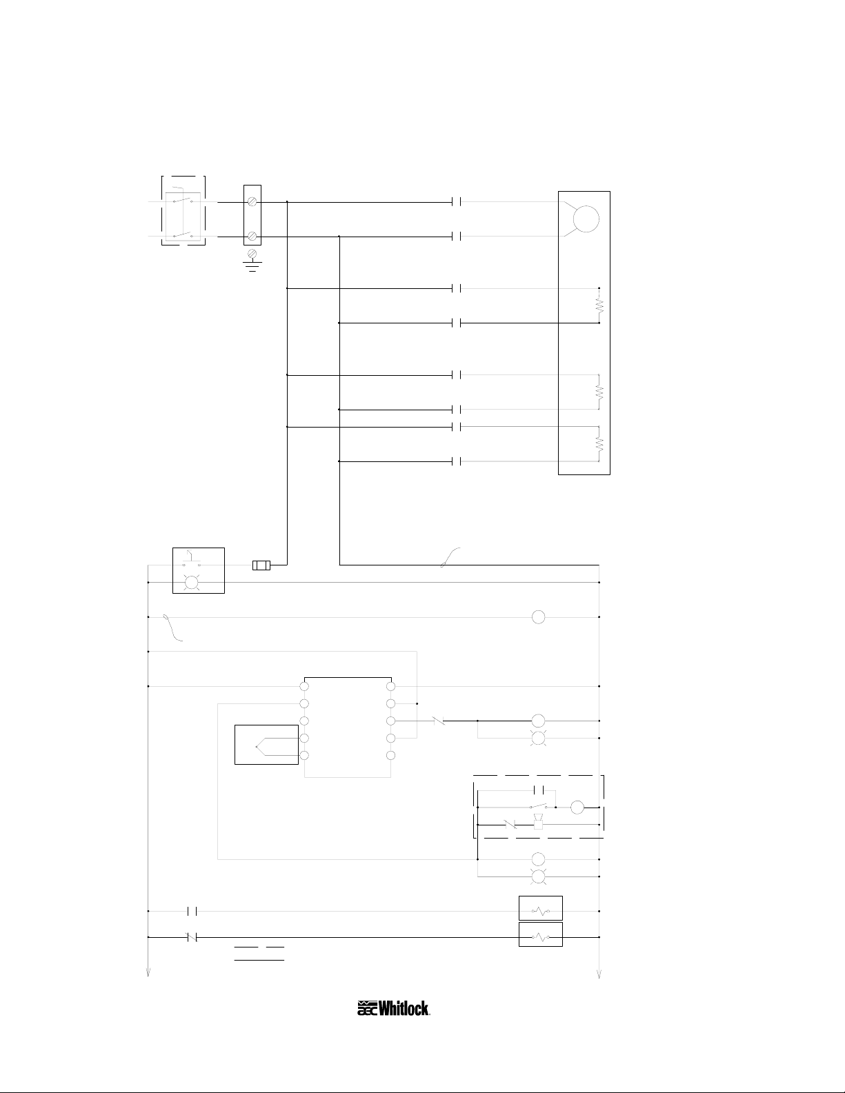
Figure 6
Typical WD10MR/FR Electrical Schematic, Drawing 1
115/1/60
1DBLK
1L1
1L1
TB1
1L3
1L1
1L2
1M
1M
1T1
1MTR
1T2
BLOWER
CONTROL POWER
4
4
4
4
OFF ON
G
18GA RED (TYP)
SUBPANEL
GROUND
GROUND
1RS
3
OX
1LT
1L1
1L2
1L1
1L2
1L1
1L2
2FU
1L1
1L2 1L2
1C
1C
2C
2C
3C
3C
18GA WHT (TYP)
1H1
PROCESS
1HTR
2HTR
3HTR
1L2
1L2
HEATER
LEFT
REGENERATION
HEATER
RIGHT
REGENERATION
HEATER
POWER ON
BLOWER CONTACTOR
1H2
2H1
2H2
3H1
3H2
1M
4
4
4
4
2CR
2CR
LEGEND:
5 10
5
4
3
PROCESS
2
TEMPERATURE
CONTROLLER
[-]RED
TYPE "K"
5 5
[+]YEL
1TC
1L2
4
9
8
7
61
1CR
6
4
A054616
OPTIONAL COMPONENTS
COMPONENTS LOCATED EXTERNALLY
OF CONTROL ENCLOSURE
7
518
5
5
8
18
1C
OPTIONAL AUDIBLE ALARM
3CR
2RS
3CR
19
1AH
1CR
R
1SOL
2SOL
1L2
1L2
1L2
1LTG1LT
3CR SILENCE BUTTON
1AH
1L2
1L2
2LT
1L2
1L2
PROCESS HEATER CONTACTOR
"PROCESS HEATER ON"
AUDIBLE ALARM
PROCESS HIGH TEMP. RELAY
"HI-PROCESS AIR TEMP"
RIGHT VALVE SHIFT SOLENOID
LEFT VALVE SHIFT SOLENOID
1L2
Page 18 WDMR and WDFR Series Dehumidifying Dryers
Page 20
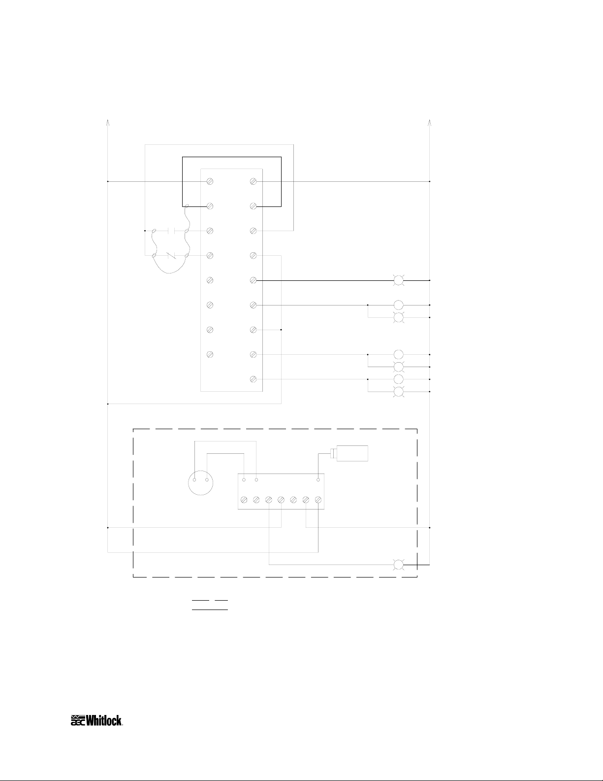
Figure 6
Typical WD10MR/FR Electrical Schematic, Drawing 2
L2
1L2
115/1/60
1L2
4 1L2
10
1PLC
L1
44
COM
99
11
12
-
1DMTR
000
001
002
003
004
005
+
1M
10
1CR
10
18GA BLUE 24VDC
INPUT WIRING
4
DEW POINT
METER
4
+24V
-24V
10
COM
4
0
13
1
14
COM
4
2
15
3
16
OPTIONAL DEW POINT CONTROL
RED BLK
1DPB
4
17 4
3LT
1L2
G
2CR
14
15
16
1DPT
7654321
1L2
4LT
G
2C
5LT
G
3C
6LT
G
"LEFT BED IN REGEN"
1L2
BED SHIFT RELAY
1L2
"RIGHT BED IN REGEN"
1L2
LEFT BED CONTACTOR
1L2
"LEFT BED HEATER" ON
1L2
RIGHT BED CONTACTOR
1L2
"RIGHT BED HEATER" ON
DEW POINT CONTROL BOARD
1L2
4
17
4
A054616
7LT
G "HIGH DEW POINT"
1L2
LEGEND:
OPTIONAL COMPONENTS
COMPONENTS LOCATED EXTERNALLY
OF CONTROL ENCLOSURE
Refer to your Customer Information Packet on actual drawings for your specific dryer.
WDMR and WDFR Series Dehumidifying Dryers Page 19
Page 21
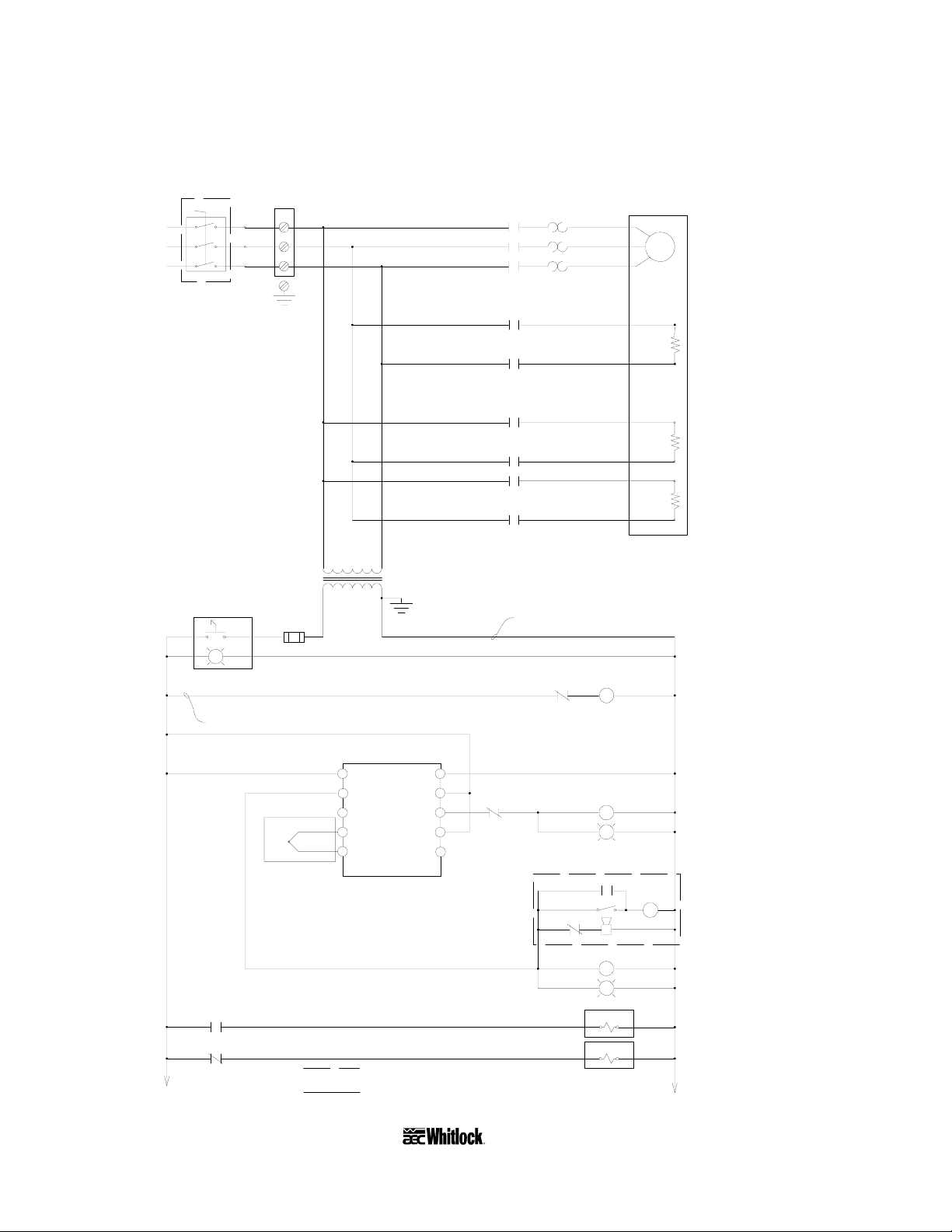
Figure 7
Typical WD25MR/FR, WD50MR/FR Electrical Schematic, Drawing 1
1M 1OL
1M 1OL
1T1
1T1
1T2
1T2
1T3
1T3
1MTR
BLOWER
L1
L2
L3
OPTIONAL
DISCONNECT
1DISC
1DBLK
TB1
1L1
TB1
1L2
TB1
1L3
1L1
1L2
1L3
CONTROL POWER
4
4
4
4
OFF ON
G
18GA RED (TYP)
SUB-PANEL
GROUND
GROUND
1RS
OX
1LT
2FU
3
1L2
1L1
1L2
1L1
1L2
1L1 1L3
115V
1
1L3
1T
1T
GND
2 2
1C
1C
2C
2C
3C
3C
18GA WHT (TYP)
1H1
PROCESS
1HTR
2HTR
3HTR
2
2
HEATER
LEFT
REGENERATION
HEATER
RIGHT
REGENERATION
HEATER
POWER ON
1H2
2H1
2H2
3H1
3H2
1OL
20
1M BLOWER CONTACTOR
4
TYPE "K"
TC
5 5
2CR
4
2CR
4
4
LEGEND:
[-]RED
[+]YEL
4
5
5
4
3
PROCESS
TEMPERATURE
CONTROLLER
2
1
2
10
4
9
8
7
6
1CR
6
4
A0547615
OPTIONAL COMPONENTS
COMPONENTS LOCATED EXTERNALLY
OF CONTROL ENCLOSURE
2
7 1LTG1LT
518
5
5
8
18
1C PROCESS HEATER CONTACTOR
OPTIONAL AUDIBLE ALARM
3CR
2RS
3CR
19
1AH
1AH
1CR
2LT
R
1SOL1SOL
1SOL1SOL
2
2
"PROCESS HEATER ON"
2
3CR SILENCE BUTTON
2
AUDIBLE ALARM
2
PROCESS HIGH TEMP. RELAY
2
"HI-PROCESS AIR TEMP"
2
RIGHT VALVE SHIFT SOLENOID
2
LEFT VALVE SHIFT SOLENOID
2
Page 20 WDMR and WDFR Series Dehumidifying Dryers
Page 22
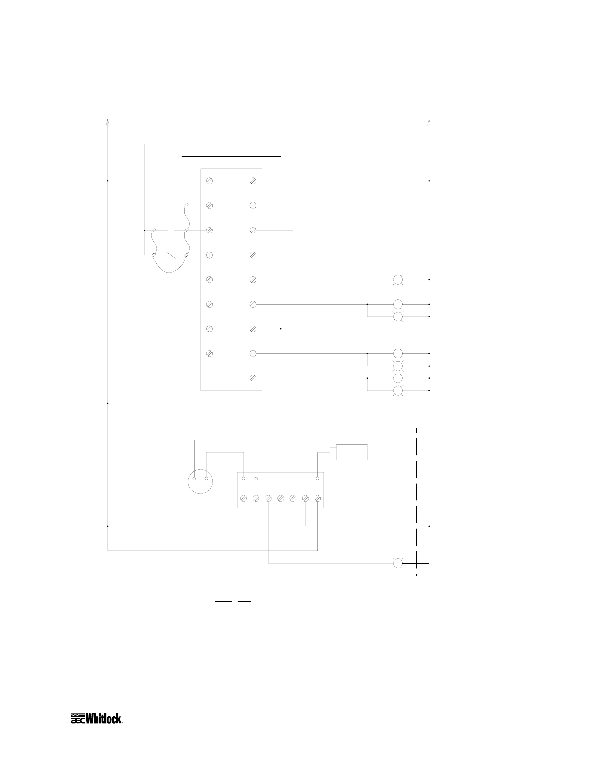
Figure 7
Typical WD25MR/FR, WD50MR/FR Electrical Schematic, Drawing 2
4 2
10
1PLC
L1
44
L2
2
2
COM
99
11
12
-
1DMTR
000
001
002
003
004
005
+
1M
10
1CR
10
18GA BLUE 24VDC
INPUT WIRING
4
DEW POINT
METER
4
+24V
-24V
10
COM
4
0
13
1
14
COM
4
2
15
3
16
OPTIONAL DEW POINT CONTROL
RED BLK
1DPB
4417
3LT
2
G
2CR
14
15
16
1DPT
7654321
2
4LT
G
2C
5LT
G
3C RIGHT BED CONTACTOR
6LT
G
"LEFT BED IN REGEN"
2
BED SHIFT RELAY
2
"RIGHT BED IN REGEN"
2
LEFT BED CONTACTOR
2
"LEFT BED HEATER" ON
2
2
"RIGHT BED HEATER" ON
DEW POINT CONTROL BOARD
2
4
17
4
A0547615
2
7LT
G
"HIGH DEW POINT"
LEGEND:
OPTIONAL COMPONENTS
COMPONENTS LOCATED EXTERNALLY
OF CONTROL ENCLOSURE
Refer to your Customer Information Packet on actual drawings for your specific dryer.
WDMR and WDFR Series Dehumidifying Dryers Page 21
Page 23
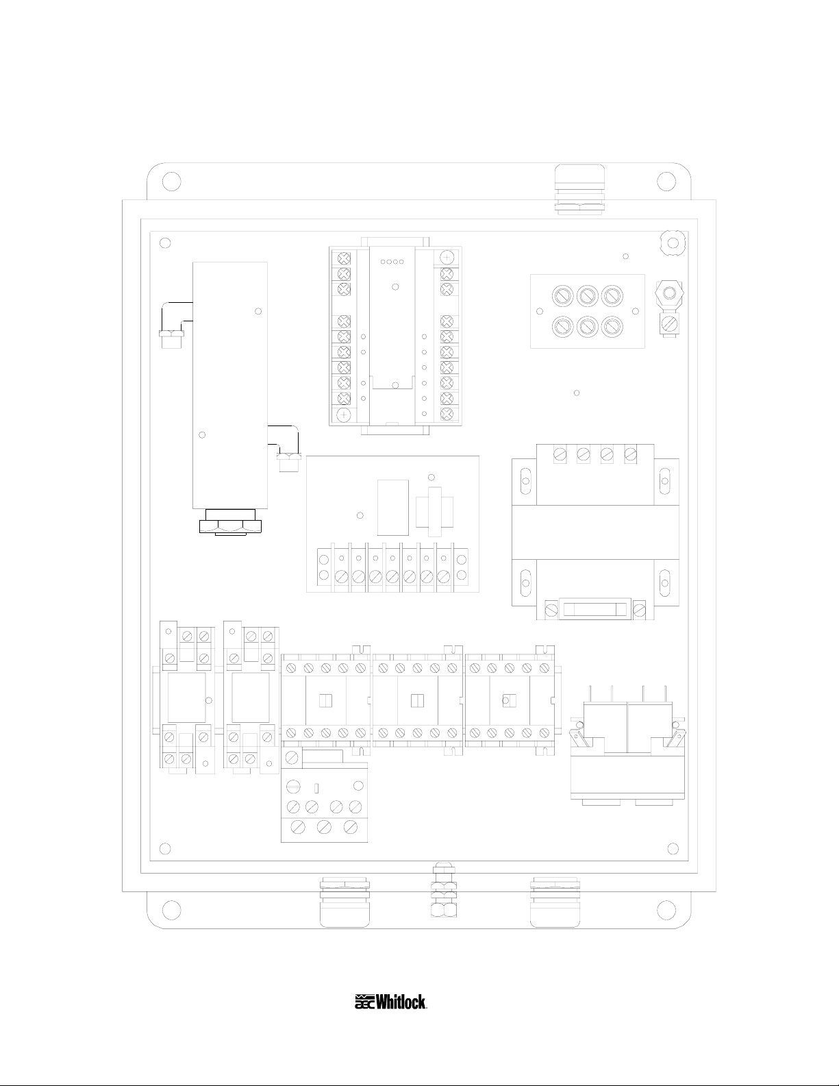
Figure 8
Typical Control Subpanel Layout
1DPT
1DBLK
omron
SYSMAC mini
PLC
1T
1DPB
2CR1CR
3C2C1M
1FU
GRD
1C
10L
A0547616
Refer to your Customer Information Packet on actual drawings for your specific dryer.
Page 22 WDMR and WDFR Series Dehumidifying Dryers
Page 24

3-5 Making Dryer/Drying Hopper Process Air
Connections
Floor Mount Models (FR)
Use high-temperature flexible dryer hose or rigid tubing to connect the dryer to the drying
hopper.
Keep the delivery hose to the drying hopper as short as possible to minimize heat loss. We
strongly recommend insulated hose for maximum energy savings.
Do not use insulated hose on the return from the drying hopper.
Do not shorten the return hose. The return air to the blower must be 150°F (66ºC) or
below. If the return air temperature is not below this point, you should purchase and install
the optional aftercooler to remove excessive heat. Consult AEC, Inc. for more information.
Aftercooler considerations also apply to machine-mount models.
Make sure that hoses are not kinked or collapsed.
Drying hopper air inlet and outlet locations vary, but always connect hoses so the dry process
air from the dryer enters the bottom of the drying hopper and flows out the top to return to
the dryer inlet.
3-6 Drying Hopper Air Trap Considerations
AEC/Whitlock’s exclusive air trap assembly on the top of the drying hopper prevents ambient air
from contaminating the material being dried.
Keep the material level at the mid point of the air trap for maximum efficiency.
Use a hopper loader or vacuum conveying system to maintain the proper material level.
3-7 Installing the Optional Aftercooler
Air-cooled WD10MR/FR and WD25MR/FR models use an air-to-air heat exchanger as an
aftercooler. No cooling water is required for this design. Return air from the hopper passes
through the air filter to trap fines and dust before entering the heat exchanger.
WDMR and WDFR Series Dehumidifying Dryers Page 23
Page 25
Installing Air Hose
Water-Cooled Aftercooler for WD50MR Dryers
Air is routed from the bottom of the aftercooler up through the top.
• Connect the hot incoming air hose from the drying hopper to the bottom 2” (about 51 mm)
tube stub with a hose clamp.
• Connect the cooled outgoing air hose to the 2” (about 51 mm) tube at the top of the cooler.
Run this hose to the inlet of the process air filter on top of the dryer.
Figure 9
Aftercooler Design Specifications
Entering air temp. Leaving air temp. Entering water temp. Leaving water temp. Initial flow rate
ºF ºC ºF ºC ºF ºC ºF ºC gpm lpm
250ºF 121ºC 130ºF 54ºC 80ºF 27ºC 85ºF 29ºC 3 gpm 11 lpm
Installing Water Lines
WD50MR/FR Models
• Use the ½” (about 13 mm) brass pipe nipples for water line connections. Connect the
entering water line to the pipe nipple, located in the center of the cover.
• Make sure you grip the nipple tightly when attaching a fitting. Doing so prevents damage
to the soft copper coils. You should make connections with flexible hose to allow removing
the coil assembly for cleaning.
• The aftercooler is designed to utilize either tower or city water as warm as 85ºF (29ºC).
Recommended flow rate is one to three (1 to 3) gallons per minute (4 to 11 liters per
minute).
Important!
You must use an aftercooler on WD50MR/FR models to operate
at process supply temperatures of 180ºF (82ºC) or below.
You are required to use a chilled water supply of 50ºF (10ºC) to
pre-condition the dryer return air so the dryer can properly
achieve low dew points and process temperatures.
If an aftercooler is used with a drying system, AEC highly recommends that a
high temperature return air filter element is substituted for the standard
element. Order Part No. A0538636 from the AEC/Whitlock Parts Department.
Page 24 WDMR and WDFR Series Dehumidifying Dryers
Page 26

4 Level 1 Controllers
Your dryer comes with the standard Level 1 control panel or the optional Level 2 control panel.
This chapter discusses the features of each, starting with Level 1 features. Level 2 features
begin in Chapter 5 on Page 33, with a graphic of the Level 2 control panel in Figure 13 on Page
34.
4-1 Level 1 Control Panel Indicator Lights
Control Power On
Control Power On indicator lights when the dryer control circuit energizes.
The
Process Heater On
The
Process Heater On indicator lights when the process air heater energizes.
High Process Air Temperature Alarm
The
High Process Air Temperature alarm indicator lights when the temperature at the process
air thermocouple is above the set high alarm value. When the indicator lights, the alarm relay
energizes and all the heaters turn off while the blower remains on to cool the dryer.
• The alarm mode and value are factory-set to track 25° above the process set point. The
alarm value is a deviation above the process set point, and the user can adjust it.
• When the temperature at the process thermocouple returns to within the acceptable range,
the alarm output de-energizes and all the heaters turn on again automatically.
• You can alter the alarm range. See Section 6-5 on Page 43 for more information.
Regen Heater On
The Regen Heater On indicator lights when the left or right bed regeneration heater is on.
Left Bed Regenerating and Right Bed Regenerating
The lit
being regenerated (off-line).
High Dew Point Alarm (optional)
The
dew point alarm point, factory set at -10°F (-23ºC).
Left Bed Regenerating or Right Bed Regenerating LED indicates the bed currently
High Dew Point alarm indicator lights when the process air delivery dew point exceeds the
WDMR and WDFR Series Dehumidifying Dryers Page 25
Page 27

Figure 10
Typical Enclosure with Level 1 Control Panel, Optional Dew Point System, Disconnect
Process Delivery
Temperature
180
OMRON
-
35
-
40
ON
OFF
Process Dew Point
-
-
-
25
-
30
DEW POINT (F)
1520
-
10
Process
Heater On
Left Bed
Heater
Left Bed
In Regen
-
5
0
HI-Process
Air Temp
Right Bed
Heater
Right Bed
In Regen
HI-Dew
Point
Page 26 WDMR and WDFR Series Dehumidifying Dryers
Page 28

Figure 11
Level 1 Process Air Temperature Control Graphic Layout
Process Delivery
Temperature
ON
180
OFF
OMRON
Process
Heater On
Left Bed
Heater On Heater On
Left Bed
In Regen
HI-Process
Right Bed
Right Bed
4-2 Level 1 Switches and Meters
ON/OFF Rocker Switch
The ON/OFF rocker switch energizes or de-energizes dryer control power.
Dew Point Meter (Optional)
Air Temp
In Regen
The Dew Point meter indicates the current process air delivery moisture content.
4-3 Level 1 PLC Controller
WD10MR/FR through WD50MR/FR dryers are equipped with an Omron programmable logic
controller (PLC).
• The “brick” type PLC has ten (10) I/O points: six (6) inputs and four (4) outputs.
• All inputs are 24 VDC; all outputs are 115 VAC.
• All programming and logic is factory-installed on a non-removable EEPROM and cannot
be modified.
WDMR and WDFR Series Dehumidifying Dryers Page 27
Page 29

4-4 Level 1 Process Air Temperature Controller
Standard AEC/Whitlock dryers use a microprocessor-based PID temperature controller for
maintaining process air temperature. The controller is a modular, self-contained unit you can
remove from the mounting housing. All parameters except for the process air set point are set
and adjusted at the factory; no field adjustment to the internal controls is normally necessary.
4-5 Level 1 PLC LED Indicators
Input LED Indicators
Process Blower On (Indicator 000)
The amber Process Blower On LED lights when the blower contactor energizes.
Hi-Process Air Temp (Indicator 001)
The amber
acceptable operating range. The LED turns off during a high process air temperature condition.
Hi-Process Air Temp LED lights when the process air temperature is within an
Output LED Indicators
Left Bed In Regen (Indicator 100)
The amber Left Bed In Regen LED lights when the left bed is in regeneration.
Right Bed In Regen (Indicator 101)
The amber
Left Bed Heater On (Indicator 102)
The amber Left Bed Heater On LED lights when the left bed regenerates and is in the heat-up
portion of the regeneration cycle.
Right Bed Heater On (Indicator 103)
The amber
up portion of the regeneration cycle.
Right Bed In Regen LED lights when the right bed is in regeneration.
Right Bed Heater On LED lights when the right bed regenerates and is in the heat-
Status LED Indicators
Power Indicator
The green
Page 28 WDMR and WDFR Series Dehumidifying Dryers
Power LED lights when power is applied to the PLC (100-240 VAC, 50/60 Hz).
Page 30

Run Indicator
The green Run LED lights when the PLC executes the program and operates normally.
Link Indicator
The Link indicator is not used.
Error Indicator
The red
operation (the
Error LED lights when an internal self-diagnosis detects an error and stops PLC
Run LED is off).
4-6 Level 1 Temperature Controller LED Indicators
888
During normal operation, the process value LED on the controller displays the process
temperature at the
messages if an error occurs. Press the
point.
The orange On Output LED lights when control output energizes the process air heater.
The AL alarm indicator lights when the process air temperature rises more than 25° from the set
point (factory default). The alarm relay in the PLC energizes when this LED lights. The
audible/visual alarm actuates if the dryer is so equipped. All heaters turn off and the blowers stay
on to cool the heaters. You can adjust the alarm value; see Section 6-5 on Page 43 for more
information.
Deviation Indicators
Process Value Numeric LED
TO PROCESS thermocouple. It also lists parameters during setup and error
Mode key once to display the process temperature set
ON
Output LED
AL
Alarm LED — High Temperature Alarm
∆ Arrow Up
The arrow up indicator lights when actual temperature is higher than the set point.
In Range
The in-range square indicator lights when temperature deviation is within plus or minus one
percent (±1%) of the set point.
WDMR and WDFR Series Dehumidifying Dryers Page 29
Page 31

∇ Arrow Down
r
r
r
(
)
y
The arrow down indicator lights when actual temperature is lower than the set point.
Figure 12
Level 1 PLC Controller Details
Up indicato
In Range
indicato
Down indicato
180
Process Value
numeric LED
Down key
Mode key
Membrane
ke
hidden
OMRON
Up key
4-7 Level 1 Temperature Controller Keys
Figure 6
OMRON
The lock-out membrane key provides protection against unauthorized set point changes when
used in conjunction with the internal protection switch. If the internal protection switch is
you must press this key simultaneously with the
key to change the set point or alarm point. If the protection switch is
Membrane Key (Hidden)
ON,
Up arrow key or the Down arrow
OFF, you can still make
changes by pressing the
Mode Key
The mode key lets you switch between set point and alarm parameters. See Sections 6-4 on Page
42 and 6-5 on Page 43, and Section 7-8 starting on Page 54 for more information.
Page 30 WDMR and WDFR Series Dehumidifying Dryers
Up arrow key or the Down arrow key.
Page 32

Note: During normal operation, use this key to change the set point or alarm setting only. The
factory alarm setting is 25° above the set point and is satisfactory for most applications.
Down Key
The Down arrow key lets you lower the process air set point temperature. During setup, it lets
you decrease the value of the parameter displayed on the set point LED readout.
Up Key
The Up arrow key lets you raise the process air set point temperature. During setup, it lets you
increase the value of the parameter displayed on the set point LED readout.
WDMR and WDFR Series Dehumidifying Dryers Page 31
Page 33

- Notes -
Page 32 WDMR and WDFR Series Dehumidifying Dryers
Page 34

5 Additional Level 2 Controller Features
5-1 Level 2 Control Panel
Optional
The optional Level 2 controller option operates identically to the standard Level 1 controller
covered in the previous chapter. However, this controller adds front-mounted
START/STOP
Air Temp.
and TEMP. SET POINT NORMAL/SHIFT switches and Blower On, High Regen
, and Dirty Filter indicators. The following page shows a typical Level 2 controller.
5-2 Level 2 Control Panel Indicator Lights
Process Heater On
The Process Heater On indicator lights when the process air heater is energized.
Hi-Process Air Temp
SYSTEM
The
Hi-Process Air Temp alarm indicator lights when the temperature at the process air
thermocouple is above the high alarm set value. This indicator lights when the alarm relay
energizes; all heaters turn off and the blower remains on.
The alarm mode and value are factory-set to track 25º above the process set point. The alarm
value is a deviation above the process set point. When the temperature at the process
thermocouple returns to within the acceptable range, the alarm output de-energizes and all
heaters turn on again automatically. You can adjust the alarm value; see Section 6-5 on Page 43
for more information.
WDMR and WDFR Series Dehumidifying Dryers Page 33
Page 35

Optional Level 2 Controller
Process Delivery Temperature
Figure 13
ºF
POWER ON
PV
1 8 0
SV
1 8 0
OUT STOP HB
TEMP. SET POINT
SYSTEM START
NORMAL
Process
Heater on
Left Bed
Heater
ALM2ALM1
Left Bed
In Regen
Blower
On
Hi-Process
Air Temp
Right Bed
Heater
Right Bed
In Regen
High Regen
Air Temp.
Process Air Dew Point
High
Dew Point
Dirty
Filter
- 20
- 25
- 30
- 35
- 40
DEW POINT (ºF)
- 15
- 10
- 5
0
OFF
STOP
SHIFT
Page 34 WDMR and WDFR Series Dehumidifying Dryers
Page 36

Left Bed Heater
The Left Bed Heater indicator lights when the left bed regenerates and is in the heat-up portion
of the regeneration cycle.
Right Bed Heater
The
Right Bed Heater indicator lights when the right bed regenerates and is in the heat-up
portion of the regeneration cycle.
Left Bed In Regen
The
Left Bed In Regen LED lights when the left bed is in regeneration.
Right Bed In Regen
The
Right Bed In Regen LED lights when the right bed is in regeneration.
Blower On
The
Blower On indicator lights when the blower energizes.
High Regen Air Temp.
The
High Regen Air Temp. alarm indicator lights when the thermocouple above the
regeneration heater assembly senses an abnormally high temperature.
Caution!
Do not adjust the factory set point of 2CNTL and 3CNTL,
the 1/16 DIN panel-mounted temperature controller
located inside the enclosure.
The regeneration heaters shut down until the temperature falls below the alarm point. The
regeneration blower continues to run for cooling the heaters and desiccant bed. This indicator
shuts off and the alarm condition clears when the temperature drops below the alarm point. The
heaters re-energize automatically.
High Dew Point
The
High Dew Point alarm indicator lights when the process air delivery dew point exceeds the
dew point shift point.
Dirty Filter
The
Dirty Filter alarm indicator lights when the pressure differential across the process air return
filter exceeds the pressure switch setting. Replace or clean the filter when this indicator lights.
The indicator and the alarm condition clears after you service and reinstall the filter.
WDMR and WDFR Series Dehumidifying Dryers Page 35
Page 37

5-3 Level 2 Switches and Meters
POWER ON
Press the POWER ON rocker switch to energize or de-energize control power to the dryer.
SYSTEM START
Press the
position to shut down the dryer when it is operating.
TEMP. SET POINT NORMAL
Move the
operation. Move the switch to the
temperature on the ¼ DIN controller.
ALARM SILENCE
Optional
Press the ALARM SILENCE switch to silence the horn when a high temperature alarm activates.
The alarm repeats every five minutes until the problem causing the alarm condition is cleared.
Process Air Dew Point
The Process Air Dew Point meter indicates the current process air delivery moisture content.
SYSTEM START rocker switch to start the dryer. Move this switch to the STOP
TEMP. SET POINT NORMAL rocker switch to the NORMAL position for normal
SHIFT position to raise or lower temperature to the alternate
5-4 Level 2 PLC Controller
Your optional Level 2 PLC controller uses an Allen-Bradley programmable logic controller
(PLC). This “brick”-type controller has 16 I/O points: ten (10) inputs and six (6) outputs, and all
ten (10) inputs and six (6) outputs are 115 VAC.
All programming and logic is factory-installed on an EEPROM chip, and cannot be modified. A
battery backup retains programming if power fails. Battery life is five (5) years at room
temperature.
If the alarm indicator blinks intermittently, replace the battery within one (1) week.
Page 36 WDMR and WDFR Series Dehumidifying Dryers
Page 38

5-5 Level 2 Process Air Temperature Controller
Your AEC/Whitlock dryer uses a microprocessor-based PID controller for maintaining process
air temperature. The controller is a modular, self-contained unit that can slide out from the
housing. All parameters except the process air set point are set and adjusted at the factory; no
field adjustment to the internal controls is normally necessary.
Figure 14
Level 2 PLC Controller Details
PV
Output indicator
Stop indicator
Mode key
Level key
ºF
1 8 0
SV
1 8 0
ALM2ALM1
OUT STOP HB
Process air temperature
Process air temperature set point
High temperature alarm indicator
Not used
Not used
Down key
Up key
5-6 Level 2 Temperature Controller LED Indicators
—— PV ——
During normal operation, the red process value (PV) numeric LED indicator displays the process
temperature at the To Process thermocouple. It also lists parameters during setup and error
messages if any errors occur.
—— SV ——
During normal operation, the green set value (
set point you selected for the dryer. The dryer then maintains this set point temperature. This
LED indicator also displays parameter and pre-set function values during setup.
ALM1
High Temperature Alarm Indicator
The ALM1 high-temperature alarm indicator lights when the process temperature exceeds the set
point temperature by more than the alarm deviation value. This alarm output de-energizes the
heaters. Heaters re-energize when the temperature falls within the acceptable range.
Process Value Numeric LED
Set Value Numeric LED
SV) numeric LED indicator displays the process
WDMR and WDFR Series Dehumidifying Dryers Page 37
Page 39

ALM2
ALM2 Indicator
The ALM2 indicator is not used.
OUT
Output Indicator
The
OUT indicator lights when the controller signals the process heaters to be energized.
STOP
Stop Indicator
The STOP indicator is not used.
HB
HB Indicator
The HB indicator is not used.
5-7 Level 2 PLC LED Indicators
Input LED Indicators
Blower Input (I/0)
The Blower Input indicator lights when the blower contactor energizes.
Hi-Process Air Temp (I/1)
The
Hi-Process Air Temp indicator lights when process air temperature is outside the
acceptable operating range set as
Hi-Regeneration Air Temp — Left Bed/Right Bed (I/2, I/3)
The Hi-Regeneration Air Temp indicator is off during a regeneration bed high temperature
condition. This condition is based on the set point of
Start/Stop Input (I/5)
The
Start/Stop Input indicator lights when the dryer is running. It goes off when the dryer stops
during a normal shutdown sequence.
Note: Inputs
I/6 through I/8 are not used.
ALM1 on the temperature controller.
2CNTL and 3CNTL.
Page 38 WDMR and WDFR Series Dehumidifying Dryers
Page 40

Alarm Silence Input (I/9)
Optional
The Alarm Silence Input indicator lights momentarily when you silence the alarm horn.
Output LED Indicators
Blower On (O/0)
The Blower On indicator lights when the blower energizes.
Process Heater Enable (O/1)
The Process Heater Enable indicator lights when the process heaters can be energized. This
condition occurs when no blower failures or high temperature conditions exist.
Right Bed Regeneration Output (O/2)
The right
Bed Regeneration Output indicator lights when the right bed regenerates. When this
indicator is off, the left bed is energized.
Left/Right Regen Heater Output (O/3, O/4)
The
Regen Heater Output indicator lights when the indicated bed regeneration heater
energizes.
Alarm Horn Output (O/5)
Optional
The Alarm Horn Output indicator lights at a high process temperature condition.
Status LED Indicators
Power
The Power indicator lights when the PLC receives 115V control power.
Run
The Run indicator lights when the PLC executes the program in normal conditions.
Fault
The
Fault indicator lights when the PLC program has a problem or failure condition.
Force
The
Force indicator is not used.
WDMR and WDFR Series Dehumidifying Dryers Page 39
Page 41

5-8 Level 2 Temperature Controller Keys
Level Key
Press the Level key for two (2) seconds or more to select the next of three (3) indication
levels (0, 1, or 2) when you set specific control parameters. The PLC controller defaults to Level
0 on power-up.
Mode Key
The Mode key lets you scroll through parameters you can set in indication Levels 0 and
1. See Section 6-5 on Page 43 for more information.
Important!
During normal operation, use the Mode key
to change alarm settings only.
Factory alarm settings are 25º
above and below the set point,
and are satisfactory for most applications.
Down Key
The Down key lets you lower the process air set point temperature. During setup, it lets
you decrease the value of the parameter displayed on the
screen.
Up Key
The
increase the value of the parameter displayed on the
screen.
Up key lets you raise the process air set point temperature. During setup, it lets you
—— SV ——
—— SV ——
SV (set value) LED
SV (set value) LED
5-9 Level 2 Optional Communications Protocols
For SPI, RS-232C, RS-422, and RS-485 communications, a connection port on the electrical
cabinet lets you easily connect to your host computer. The connection port is a direct pin-to-pin
extension from the plug on the back of the temperature controller. Refer to the control module
communication manual (AEC part no. A0535959) for more information on pinouts. See
electrical schematic drawings A0550656 through A0550658 for more information on SPI
communications.
Page 40 WDMR and WDFR Series Dehumidifying Dryers
Page 42

WDMR and WDFR Series Dehumidifying Dryers Page 41
Page 43

6 Startup, Shutdown, and Operation
6-1 Pre-Startup Checks
Check the process and return hoses for tight connections.
Check all companion equipment, such as the drying hopper; verify that the loading system is
ready for operation.
Verify that all dryer electrical connections are tight.
Important!
Clean the rust-preventing oil from inside the drying hopper.
Failure to clean the hopper
fouls the desiccant
and voids your warranty!
6-2 Startup
1. Close the slidegate at the bottom of the drying hopper.
2. On three-phase models, make sure that the blower turns in the right direction before you
fill the hopper.
3. Fill the drying hopper with material.
4. Turn on (energize) the disconnect switch in your power drop, then turn on the one on the
dryer.
5. Turn the on/off switch to
The blower starts and the proper control panel indicators light.
6. If your dryer has a water-cooled aftercooler, make sure that sufficient cooling water
flows properly through the coil, and you have bled any trapped air from the system. Make
sure that the aftercooler has the proper supply water temperature.
ON.
7. Set the process set point on the temperature controller.
8. After the proper pre-drying time for the initial hopper fill has elapsed, fully open the
drying hopper slide gate.
Note: To allow proper residence time during continuous processing, maintain the material level
in the hopper at the midpoint of the air trap assembly.
Page 42 WDMR and WDFR Series Dehumidifying Dryers
Page 44

6-3 Shutdown
1. Turn off the conveying system supplying the drying hopper.
2. When processing is complete, close the hopper slide gate and shut down any in-line
companion equipment, such as the aftercooler.
3. Level 1 Controls: Turn the
On/Off selector switch to OFF.
Level 2 Controls: Push the Run/Stop rocker switch to the OFF position.
The unit shuts off after completing the regeneration cycle.
4. If needed, empty the drying hopper.
5. For maintenance or a long term shutdown, open (de-energize) the electrical disconnects
at the dryer and at the power drop.
6-4 Setting the Process Air Temperature
Level 1 Controllers
To change the process air temperature set point with the dryer running:
1. Press once.
2. Press
- or -
Press
to raise the set point to the desired temperature.
to lower the set point to the desired temperature.
3. Press
twice to restore.
Level 2 Controllers
To change the process air temperature set point with the dryer running:
• Press to raise the set point to the desired temperature.
• Press
to lower the set point to the desired temperature.
WDMR and WDFR Series Dehumidifying Dryers Page 43
Page 45

6-5 Setting the High Temperature Alarm
To change the process air temperature alarm setting:
1. Press twice.
2. When the AL LED lights, press and to set the high temperature alarm value
you want.
Note: The high temperature alarm value is a deviation of the process air temperature set point.
The alarm value tracks the set temperature. If the high temperature alarm is set to
high temperature alarm occurs if the process air temperature rises more than 25° above
the process air temperature set point.
3. Press again to restore.
The process air temperature readouts display.
The high temperature alarm is now set.
25, a
6-6 Temperature Controller Internal
Switches
The controller is set up and tested at the factory for optimum
operation, and the internal switches don’t need adjustment. If the
controller doesn’t work properly, or if you suspect that someone
has accidentally changed your settings, see Section 7-8 on Page 54
for more information.
6-7 Enabling the Temperature Controller Anti-
Tamper Lockout Switch
Level 1 Controllers
The PROTECT OFF slide switch prevents unauthorized changes to set points. If the switch is in
ON position, the Down arrow, Up arrow, and Mode keys are disabled. You
the
are only able to view the process set point and alarm settings. WD dryers are set at the factory
with protection turned
OFF. ON disables all front panel keys.
Page 44 WDMR and WDFR Series Dehumidifying Dryers
Page 46

To enable the lockout feature:
PROTECT
1. Disconnect main electrical power to the dryer.
1. Press up the latch at the bottom of the control module front panel and slide out the
control chassis.
2. Locate the slide-type switch marked
Slide it to the
ON position.
PROTECT on the circuit board.
OFF ON
3. Slide the chassis back into the control module housing.
Tamper protection is now enabled.
PROTECT
Note: You must use the
OMRON
hidden membrane key to change values. See Section 4-7 on Page
30 for more information.
Level 2 Controllers
The PROTECT slide switch prevents unauthorized changes to set points. If the switch is in the
SP or ALL position, the Down arrow, Up arrow, and Mode keys are
disabled. You are only able to view the process set point and alarm settings. WD dryers are
factory-set with the protection turned
To enable the lockout feature:
1. Disconnect main electrical power to the dryer.
1. Press up the latch at the bottom of the control module front panel and slide out the
control chassis.
2. Locate the slide-type switch marked
circuit board. Slide it to the SP or ALL position.
3. Slide the chassis back into the control module housing.
Tamper protection is now enabled.
OFF. SP or ALL disables all front panel keys.
PROTECT on the
SP OFF ALL
6-8 Changing the Display from Fahrenheit to Celsius
Level 1 Controllers
To change the display from the factory °F setting to °C:
1. Disconnect main electrical power to the dryer.
WDMR and WDFR Series Dehumidifying Dryers Page 45
Page 47

1. Press up the latch at the bottom of the control module front panel
and slide out the control chassis.
2. Locate the six-position DIP switch on the circuit board.
3. Move Switch
6 to the OFF position for Celsius.
4. Slide the chassis back into the control module housing.
Celsius Setup
ON
OFF
123456
5. Cover the
°F label with the °C label included in the information packet.
6. Reinstall the control and start the dryer unit.
Level 2 Controllers
1. Shut off power to the dryer and remove the controller from the chassis.
2. After setting all internal switch settings, set switch
switch is normally set to
OFF.
3. Insert the internal mechanism into the housing and power up the temperature controller.
(du) displays.
4. Press
to select the set value display as Celsius (ºC) or Fahrenheit (ºF).
5. Turn off the power two (2) seconds after the set value display changes.
6. Remove the internal mechanism from the housing, set pin number
switch to
OFF, replace it and turn on the power.
4 of the function switch to ON. This
4 of the function
Page 46 WDMR and WDFR Series Dehumidifying Dryers
Page 48

- Notes -
WDMR and WDFR Series Dehumidifying Dryers Page 47
Page 49

7 Maintenance
7-1 Work Rules
The installation, operation, and maintenance of this equipment is to be conducted in accordance
with all applicable work and safety codes for the installation location. This may include, but is
not limited to, OSHA, NEC, CSA, and any other local, national, and international regulations.
In addition, you must observe the following specific work rules:
Keep these operating instructions on hand and follow them when installing, operating, or
maintaining your dryer.
If the instructions become damaged or unreadable, you can obtain additional copies from
AEC/Whitlock.
Only qualified personnel familiar with this equipment should work on or with this unit.
Work only with approved tools and devices.
Disconnect power before servicing your dryer. If the disconnect switch you installed has a
lockout, lock it in the
OFF position before you perform any maintenance or service.
7-2 Servicing Process Air Filters
Important!
Operating the dryer without the process air filter installed voids your warranty!
Filter cleaning is an important part of your dryer maintenance program.
WD10MR/FR through WD50MR/FR dryers have a single cartridge canister-type filter in the
process air loop. It is mounted above the process blower on the rear of the dryer. This filter
protects the blower from plastic fines drawn in from the drying hopper. Regular filter cleaning is
essential to keep your dryer operating at peak efficiency.
You can wash or blow out the filter with compressed air, but remember—you reduce dirt
holding capacity with each washing. Washing a filter is risky, because dirt can reach the clean
side of the filter, and the filter could become damaged from high pressure washing or blowing.
You can carefully clean or wash the filter when air flow becomes restricted. Do not wash filters
more than six (6) times or use them for more than a year, whichever comes first.
Page 48 WDMR and WDFR Series Dehumidifying Dryers
Page 50

Use a detergent that won’t damage filter media. Such a detergent permits easy removal of dirt
particles through flushing and rinsing. An effective detergent removes the fine particles from the
pores of the filter media.
The filter manufacturer recommends FM 1400 washing compound. It is formulated specifically
for air filter element cleaning. It is non-sudsing and works in hot or cold water. FM 1400
contains biodegradable synthetic detergents and is non-phosphate, non-NTA. For more
information, contact Filter Service Corporation, 2603 A West Main, Farmington, NM
1-505-326-1127.
Recommendations for Cleaning and Replacing Filters
• Turn off and/or lock out electrical power to the dryer.
• Remove the threaded fastener securing the filter access cover, then remove the cover.
• Remove the nut on the center retaining rod to remove the filter cartridge.
Vacuuming
Clean a soiled filter by first vacuuming it. Vacuuming removes most large particles and surface
contaminants; you may not need to do any more for the first time you clean a filter. Use a
commercial-duty (recommended) or household vacuum cleaner. Vacuum the filter from the air
intake (dirty) side only.
Cleaning with Compressed Air
Blow clean, dry compressed air up and down the pleats, blowing out the filter from
the clean side. Remove loose dirt from the filter with compressed air or a water
hose. Compressed air should be less than 100 psi (689.5 kPa/6.89 bars). Use a
1
/8”-
dia. (3 mm-dia.) nozzle at least 2” (5 cm) away from the filter. Don’t shoot the air in
a crisscross motion against the grain of the pleats, as you could damage it.
Washing
As a last resort, wash the filter. However, do so only if the pressure drop is too
high from fine dirt embedded in the filter, or if oily mist is present near the
intake air location. Soak it in a solution of FM 1400 or comparable detergent and
warm water from five to ten minutes, then gently agitate for several minutes.
Rinse thoroughly with clean water to remove all detergent. Let the filter dry
completely before returning it to service. Do not use a light bulb to dry the filter.
You should get satisfactory filtration after second or third washings; however, dirt-
holding capacity of the filter decreases after each washing.
WDMR and WDFR Series Dehumidifying Dryers Page 49
Page 51

After each cleaning:
• Inspect the filter element. Briefly hold a light bulb behind the element and look
for any fatigued paper or residual dirt. Inspect for holes and tears by looking
though the filter toward a bright light. Check for damaged gaskets or dented
metal parts. Do not re-use a damaged filter!
• Inspect the end plates. Any end plate damage can allow air to bypass the filter.
• Look for rust on end plates and the metal core. Rust particles can flake off and contaminate
the dryer and resin.
• Check the gasket for damage. A damaged gasket allows contaminants into the process.
Replace as needed.
• Allow the filter to dry before re-using. Circulate warm air at less than 160ºF (71ºC). Do not
use a light bulb to dry the filter.
7-3 Servicing the Dew Point Monitor
The accuracy of the dew point monitor on WD10MR/FR through WD50MR/FR dryers depends
on proper operation of the dew point sensor and the control board. The dew point sensor is in the
process air stream and is therefore susceptible to contamination.
Dew point sensor life depends on:
• Air temperature and flow passing over the sensor
• The amount of fines (dust) in the process air
• The amount of plasticizer vapor in the process air
The dryer operator should monitor the initial dew point sensor readings and establish a periodic
replacement schedule as needed.
Caution!
Do not attempt to check the continuity
or resistance of the dew point sensor.
The sensor will be destroyed!
If you suspect that dew point readings on the dew point meter are incorrect, you can obtain a
dew point simulation calibrator from AEC/Whitlock (Part Number A0540143). This device
simulates various dew point outputs. It lets you confirm proper operation of the dew point
system control board.
Page 50 WDMR and WDFR Series Dehumidifying Dryers
Page 52

Caution!
Use caution when working inside the control cabinet,
as high voltage is present.
Do not attempt to make any adjustments to the
components on the dew point control board.
To check the dew point system control board:
1. Shut off the dryer, then remove the sensor cable from the sensor hex nut adapter.
2. Connect the cable to the plug on the rear of the simulator.
3. Turn on the dryer, then turn the rotary knob on the simulator to each position and note the
readings on the dew point meter on the dryer control panel. The readings should
correspond within a degree or two (1º to 2º) across the entire range.
4. If the readings agree, the control board is working properly and you should replace the
dew point sensor. If the readings do not agree, replace the control board and run the test
again to rule out the possibility of a bad sensor.
5. When you have finished testing, shut down the dryer and re-connect the control cable to
the sensor adapter.
7-4 Symptoms of Worn Desiccant
The moisture absorption capacity of desiccant used in your AEC/Whitlock dryer degrades after
an indefinite period of time. Useful life depends on variables such as material moisture content,
plasticizer vapors in the return air, and number of regeneration cycles.
Note: AEC recommends replacing desiccant every three (3) years if you run your dryer an
average of eight (8) hours per day, five (5) days per week. You should replace desiccant
more often if you run your dryer for longer time periods.
Your AEC/Whitlock dryer may need new desiccant if it exhibits any of the following symptoms:
• Plastic material is not being dried sufficiently (high scrap/reject rate).
• Air temperature at the top of the regenerating desiccant bed rapidly climbs to 350°F
(177ºC) or more shortly after the start of regeneration, even though a saturated bed has just
started heating.
• The process air dew point, measured with a portable dew point monitor, is higher than
-10°F (-23ºC) throughout the process drying cycle.
• Smoke or dust blows out of the process air outlet.
• Noticeable amounts of desiccant in the beds is a medium-brown color or darker.
WDMR and WDFR Series Dehumidifying Dryers Page 51
Page 53

If you notice any of these signs, replace the desiccant in the desiccant beds. Desiccant
replacement kits are available from the AEC/Whitlock Parts Department. If you want, an
AEC/Whitlock technician can repack desiccant beds at your site.
! WARNING !
Desiccant material causes eye irritation!
Breathing may be harmful and may cause skin irritation!
• Do not get in eyes.
• Avoid prolonged contact with skin.
• Use with adequate ventilation.
• Wash thoroughly after handling.
✚ FIRST AID ✚
In case of eye contact,
immediately flush eyes with plenty of water
for at least 15 minutes.
If irritation persists, see a physician.
7-5 Replacing Worn Desiccant
Caution!
Make sure desiccant beds are sufficiently cool
before replacing worn desiccant.
1. Disconnect electrical power to the dryer.
2. Remove the bolts securing the valve assembly. Remove the valve after disconnecting
actuator wiring.
Page 52 WDMR and WDFR Series Dehumidifying Dryers
Page 54

3. Using a shop vacuum, carefully remove all desiccant from each tower.
Important!
You should properly dispose of any discarded desiccant.
Consult local disposal regulations for more information.
4. Inspect each lower desiccant screen and insulation liner for tears or burn-through spots.
Replace as needed.
5. After cleaning each chamber, add a level layer of half the large bead desiccant on top of
the screen. Next, carefully add the full amount specified per bed of small bead desiccant.
Amounts are listed in the Required Desiccant Amounts per Bed table below. Smooth the
top level, and finally add another layer of the remaining large bead desiccant to the top.
Make sure this layer is level and smooth.
6. Repeat the previous step for the other bed.
7. Inspect the gaskets on the valve assembly. Replace as needed.
8. Remove heater elements from the heater plate assembly.
9. Re-install the valve and reconnect actuator wiring.
Figure 15
Required Desiccant Amounts per Bed
Dryer Large bead (Type 13X) Small bead (Type 13X) Total per bed
model Part no. lbs. Kg Part no. lbs. Kg lbs. Kg
WD10MR W00018050 1.0 0.454 W00018051 3.0 1.362 4.0 1.816
WD25MR W00018050 2.0 0.908 W00018051 7.0 3.178 9.0 4.086
WD50MR W00018050 3.0 1.362 W00018051 15.0 6.810 18.0 8.172
7-6 Replacing the Process Heater
WDMR and WDFR Series dehumidifying dryers use single-phase Calrod-type heater elements
mounted in the center compartment below the desiccant beds. The wattage of the heater varies
with model, voltage, temperature range, etc., but the replacement procedure is the same.
! WARNING !
Disconnect and lock out power before you replace heater elements!
WDMR and WDFR Series Dehumidifying Dryers Page 53
Page 55

Procedures
1. Let the dryer cool down thoroughly before removing heater elements.
2. Remove the four bolts securing the process heater access cover.
3. Sketch the heater wiring configuration so you can properly re-wire the heater.
4. Remove the wires to the heater plate assembly you are removing or replacing.
5. Remove the bolts securing the heater plate assembly, and slide out the assembly.
6. Remove the heater from the mounting plate by removing the large brass nuts and
washers.
7. Remove heater elements from the heater plate assembly.
8. Re-install the heater and heater plate assemblies in reverse order. Install new heater
gaskets (AEC Part No. W00018316) and securely tighten all fasteners.
Caution!
Heater loops should not touch each other.
“Hot spots” lead to premature heater failure!
7. Reinstall the wires based on the sketch you made earlier.
8. Secure the heater access cover.
7-7 Replacing the Regeneration Heater
WDMR and WDFR Series dehumidifying dryers use single heater elements located below each
desiccant bed.
! WARNING !
Disconnect and lock out power before you replace heater elements!
1. Let the dryer cool down thoroughly before removing heater elements.
2. Gain access to the regeneration heaters from the right side of the dryer. Remove the cover
plate secured by four bolts.
3. Sketch the heater wiring configuration so you can properly re-assemble the heaters.
4. Remove the wiring for the heater you are replacing.
5. Remove the four bolts securing each heater mounting plate. Slide out the heater.
Page 54 WDMR and WDFR Series Dehumidifying Dryers
Page 56

6. Re-install the new heaters in reverse order. Install new heater gaskets (AEC Part No.
W00018316) and securely tighten all fasteners.
Caution!
Heater loops should not touch each other.
“Hot spots” lead to premature heater failure!
7. Re-install the wiring based on the sketch you made earlier.
8. Secure the heater access cover.
7-8 Restoring the Temperature Controller to Factory
Setup
Level 1 Controllers
If preset parameters on the controller have been tampered with and it no longer properly controls
temperature, you can restore it to the factory setup. Perform the following procedures to restore
factory setup:
1. Turn off the power switch on the graphic display and remove all electrical power to the
dryer.
1. Press up the latch at the bottom of the module front panel and slide out the control
chassis.
1. Locate the slide-type lockout switch marked
circuit board. It should be
OFF.
2. Set the rotary-type alarm mode selector switch marked
PROTECT OFF on the
ALARM to Position 2
for the upper limit alarm with standby.
3. Set the rotary temperature sensor selector switch located to the left of the
selector switch to Position 2. Your dryer is factory-equipped with Type K thermocouples;
you can use six (6) other temperature sensor types if you properly set the switch.
OFF ON
PROTECT OFF
0
9
8
7
6
5
ALARM
ALARM
1
4
2
3
WDMR and WDFR Series Dehumidifying Dryers Page 55
Page 57

Note the settings for thermocouples on the following table:
Sensor Switch Temperature range
type position °F °C
Thermocouple Type K 0 — 0 to 200
Thermocouple Type K 1 — 0 to 300
Thermocouple Type K 2 0 to 400 0 to 400
Thermocouple Type K 3 0 to 500 0 to 500
Thermocouple Type K 4 0 to 600 0 to 600
Thermocouple Type K 5 0 to 999 0 to 999
Thermocouple Type J 6 0 to 999 0 to 200
Thermocouple Type J 7 — 0 to 300
Thermocouple Type J 8 0 to 400 0 to 400
Thermocouple Type J 9 0 to 500 0 to 500
6. The function selector DIP switch marked
controller modes. It is located on the back of the display.
FUNCTION lets you select
ON
OFF
123456
FUNCTION
Put this switch in the setup configuration as shown in the following table while entering
initial control parameters.
Setup Configuration
1 ON PID Controller mode
2 OFF 20-second proportional period
3 OFF Reverse control output (heating)
4 OFF Input shift disabled
5 OFF JIS sensor standard
6 ON ºF scaling indication
7. Slide the control chassis back into the control housing. Set the remaining parameters with
the keypad.
8. Prepare your dryer for startup with a real or simulated load. Restore electrical power.
9. Turn on control power.
The
PV LED displays
10. Press the
Mode key once to toggle between the actual process display and the SV
000
(zeros), then displays the current process air temperature.
LED set value display.
The
SV LED displays the current process air temperature set point.
11. Press again.
The AL alarm indicator lights.
Page 56 WDMR and WDFR Series Dehumidifying Dryers
Page 58

12. Press and to select a setting for Alarm 1, the high temperature alarm. The
factory setting is 25.
13. Press once to restore.
14. Turn
OFF the power switch on the graphic display and remove all electrical power from
the dryer when you finish.
Figure 16
Level 1 Controller Factory Preset Parameters
Parameter
setting level
Process temperature display at power-up (°) - Actual air temperature -
Process temperature set point (°)
0
Alarm value
Parameter
description
LED
display
Level 2 Controllers
If preset parameters on the controller have been tampered with and it no longer properly controls
temperature, you can restore it to the factory setup. Perform the following procedures to restore
factory setup:
1. Turn off the power switch on the graphic display and remove all electrical power to the
dryer.
2. Press up the latch at the bottom of the module front panel and slide out the control
chassis.
3. Locate the slide-type lockout switch marked Protect on the circuit board. It should be
OFF.
4. Check to make sure that the control output relays are installed on the circuit board. Level
2 controllers use one E530S solid state relay (SSR) installed in the socket. This relay
0
switches the heaters on and off.
5. Set the rotary-type alarm mode selector switch
limit alarm with standby.
6. Set the rotary-type
WDMR and WDFR Series Dehumidifying Dryers Page 57
ALM 2 switch to position 0. This alarm is not used.
ALM 1 to position 2 for upper
8
7
8
7
9
6
ALM-1
9
6
ALM-2
1
5
0
1
5
2
3
4
2
3
4
Page 59

7. Set the rotary-type INPUT selector switch to position 2. WD Dryers are
factory-equipped with type K thermocouples; other temperature sensor types
can be used if the switch is properly set.
Refer to the following table:
Switch Sensor Temperature range
setting type °C °F
0, 8 JPT100 -199.9 to 650.0 -199.9 to 999.9
1, 9 PT100 -199.9 to 650.0 -199.9 to 999.9
2 K -200 to 1,300 -300 to 2,300
3 J -100 to 850 -100 to 1,500
4 T -199.9 to 400.0 -199.9 to 700.0
5 L 100 to 850 -100 to 1,500
6 U -199.9 to 400.0 -199.9 to 700.0
7 N -200 to 1,300 -300 to 2,300
Unit of measure is .1º (ºF or ºC). 100ºC/139.16 Ω
Unit of measure is .1º (ºF or ºC). 100ºC/138.50 Ω
Unit of measure is 1º (ºF or ºC)
8.
Function selects between four (4) control modes. Put this switch
in the set-up configuration at right (all
OFF) while entering
initial control parameters.
0
9
8
7
6
5
INPUT
O
N
1234
1
2
3
4
Available functions are:
FUNCTION
Function Switch number Switch setting Setting
Output
Control
Mode
1
2
3
Menu 4
ON Normal (Cooling) Control
OFF Reverse (Heating)
ON On/Off Operation
OFF Advanced PID Operation
ON Manual PID Tuning
OFF Fuzzy Adaptive Tuning of PID
ON Engineering Programming Menu
OFF Standard Programming Menu
9. Slide the control chassis back into the control housing. Set remaining parameters with the
keypad.
10. Prepare your dryer for startup with a real or simulated load, then restore electrical power.
Page 58 WDMR and WDFR Series Dehumidifying Dryers
Page 60

11. Turn control power ON. The PV LED displays four zeros (
current process air temperature.
Caution!
0000
), then displays the
Do not attempt to run the controller without an output load.
The contactors could be damaged!
12. Press
indicating the currently selected mode; the
selected parameter. Use
to page through Level 0 control parameters. The PV LED displays codes
SV LED shows the current setting of the
and to select a setting.
13. Set Level 0 parameters based on Figure 12 on the following page.
14. Press for at least two seconds to access Level 1 parameters. Set them using the
procedure in the previous step.
Note: You can proceed to Level 2, but these parameters are read-only. Controllers with optional
communications have user-set variables (unit address and ID) on Level
2.
15. Turn off the power switch on the graphic display and remove all electrical power to the
dryer.
WDMR and WDFR Series Dehumidifying Dryers Page 59
Page 61

Figure 17
Level 2 Controller Factory Preset Parameters
Parameter setting level Parameter description PV LED display SV LED display
Process temperature display
at power-up (º)
0
1
2
Alarm 1 value (high; º)
Proportional band (º)
Reset time (sec)
Rate time (sec)
Lower limit of control range (º)
Upper limit of control range (º)
Heating control period (º)
Shift set value (º)
Control output variable (%)
Temperature sensor type
Alarm #1 mode
These parameters display only if the #6 position of the FUNCTION selector switch is set in the ON
position.
Level 2 variables are read-only for monitoring use only. Do not set these variables!
7-9 Error Display and Output
The controller that comes with your dryer incorporates a self-diagnostic function. The table on
the following page lists process values and outputs the controller displays when errors occur.
Page 60 WDMR and WDFR Series Dehumidifying Dryers
Page 62

Figure 18
Level 1 Controller Error Messages
Note: The temperature controller has self-diagnostic functions, and displays the following error
messages to simplify troubleshooting:
Message Cause Controller output
FFF
---
FFF
(blinks)
---
(blinks )
1) Temperature has risen beyond
temperature scale range.
2) Thermistor has been short-circuited.
1) Temperature has fallen below
temperature scale range.
2) Thermistor has broken.
1) Failure has occurred in thermocouple of
platinum resistance thermometer.
2) Temperature has risen much beyond
scale range.
1) Failure has occurred in platinum
resistance thermometer.
2) Polarities (positive and negative) of
thermocouple have been reversed.
3) Temperature has fallen much below
scale range.
1) Memory failure (
E 1 1
[E11] display).
OFF during heating (reverse) action
ON during cooling (normal) action
ON during heating (reverse) action
OFF during cooling (normal) action
OFF
OFF
2) Analog-to-digital converter failure (
E 1 1
or
E33
Key operations are disabled.
[E33] display). Repair temperature
controller if recovery is not made; turn
power off once and on again.
E33
Both controller output and alarm
output are OFF
Note: When using alarm outputs, an alarm output actuates when
FFF
display. These display messages indicate when the temperature rises beyond or falls
below the temperature scale range.
Operation when Sensor Fails
Thermocouple Type
Condition Display Controller output
Break in sensor.
Note: When the output short-circuits, the ambient temperature displays.
FFF
(blinks)
and
---
OFF
messages
WDMR and WDFR Series Dehumidifying Dryers Page 61
Page 63

7-10 Entering Level 2 Controller Parameters/
Advanced Topics
The Level 2 temperature controller has two (2) standard display levels, 0 and 1, in which you can
set only specific parameters. Level 0 is the initial level and automatically enters at power up. To
change the mode to set or change a different group of parameters, hold down the
Level key
for at least one (1) second.
The screen level mode changes as shown below. Actual screens vary with models and switch
settings. The setting of Function Switch
4 determines standard or engineering programming
menus. If a screen does not display as expected, check your switch settings.
Power Up Level 0
Process Value
Set Point Setting
Alarm Mode 1 - High Temp
Alarm Mode 2 - Low Temp
Press the Level Key Press the Level Key
Standard
Programming
Menu
Output Value Display
Hysteresis
Control Period
SP0/SP1 Settings
Heater Current Value Display
Heater Burnout Alarm Value
Proportional Band
Integral Time
Derivative Time
Manual Reset Value
Level 1
Engineering
Programming
Menu
Page 62 WDMR and WDFR Series Dehumidifying Dryers
Page 64

Level 0
PV
Process Value
SV
PV
AL-1
SV
PV
AL-2
SV
0
Press a
0
Press a
0
Press a
Set Point Setting
Alarm Mode 1 Setting - High Temp
[Nothing displayed if ALM1 is set
to 0 (i.e., no alarm function is on)]
Alarm Mode 2 Setting - Low Temp
[Nothing displayed if ALM2 is set
to 0 (i.e., no alarm function is on)]
WDMR and WDFR Series Dehumidifying Dryers Page 63
Page 65

Level 1
PV
O
SV
Output Value Display
Output Value
ON/OFF Control PID Control
Press a
HYS
PV
SV
Hysteresis Setting
1.0
Press a
PV
CT
SV
Current Value
PV
HB
SV
CP
SP-0
SP-1
If Control Output is Current Output
Heater Current Display
Press a
Heater Burnout
0.0
Alarm Setting
Press a
PV
SV
Control Period Setting
20
Press a
Models with Event Input Only
PV
SV
0 Set Value 0 Setting SP0
Press a
PV
SV
Set Value 1 Setting SP1 (Temperature Shift Set Point)
0
Press a
If the Control is Set to Advanced PID
PV
P
SV
40.0
Press a
PV
I
SV
233
Press a
PV
D
SV
40
Press a
When 1= 0
PV
OFR
SV
50.0
Press a
Page 64 WDMR and WDFR Series Dehumidifying Dryers
Page 66

Output Value Screen
O
0%
Screens manipulated output variable % from 0 to 100.0%
Control Period
Set this value to match the characteristics of the process: a short control period for a fast moving
process; a long control period for a slow moving process. The factory default setting is 20
seconds. Please note that a control period of less than 20 seconds may shorten the life of a relay
output.
utput Value: 50.
20 Sec. Control Period10 Sec. Control Period
Set Point 0 (°C/°F )
Do not install a pre-set value at this set point. It tracks the SV value on Level 0. This value is
Temperature Set Point
1, which you select by the switch on the front panel of the dryer. This
feature is found only on dryers with the dual set point option.
Set Point 1
Use and to set the value for set point to 1. It is
possible to set the value regardless of whether the set
value presently selected is on or . This is
Temperature Set Point 2 when selected by the set point
switch on the dryer front panel. This feature is found only
on dryers with the dual set point option. The set point can
be selected by short-circuiting the EV1 terminals
(terminals
17 and 20) on the temperature controller.
20
17
Set point 1
20
17
Set point 0
WDMR and WDFR Series Dehumidifying Dryers Page 65
Page 67

Proportional Band
When displays on the PV screen, you can then change the proportional band (P constant)
by pressing
from 0.1° to 999.9°C/°F in units of 0.l°C/°F. The value is set at the factory to 40.0°C/°F, but this
changes as the controller auto-tunes itself.
and . The new value displays on the SV screen. You can set it in a range
Integral Time
When displays on the PV screen, you can change the integral time (I constant) by
pressing
The value is set at the factory to 233 seconds, but this changes as the controller auto-tunes itself.
and . You can set it in a range from 0 to 3,999 seconds in units of 1 second.
Derivative Time
When displays on the PV screen, you can change the derivative time (D constant) by
pressing and . You can set it in a range from 0 to 3,999 seconds in units of 1 second.
The value is factory-set to 40 seconds, but this changes as the controller auto-tunes itself.
Manual Reset Value (%)
When using P or PD control (i. e. I = O), the process value may stabilize at a value above or
below the set point of the manual reset value, which has a factory default setting of 50%. You
can adjust it upward to eliminate droop or downward to eliminate overshoot.
Note: The
Page 66 WDMR and WDFR Series Dehumidifying Dryers
P, I, D, and OFR parameters are not accessible when the control mode is set to PID
with fuzzy self-tuning; P, I, and D are set automatically to optimum values based on
current process conditions determined by the controller.
Page 68

Figure 19
Level 2 Process Temperature Controller Error Messages
Control output
Message Cause
Input temperature has
risen beyond the upper
limit of the temperature
range by more than 20
°C (68°F)
Input temperature has
fallen below the lower
limit of the temperature
range by more than 20
°C (68°F)
The thermocouple has
burned out or the short
circuit bar has been
removed. The platinum
RTD has burned out or
A and B have been
(flashes)
short circuited.
Memory failure (E111)
or analog to digital
converter failure
(E333) has occurred.
Temperature controller
must be repaired if
recovery is not made
by turning power off
once and on again.
With output unit other
than current output unit
OFF during reverse
(heating) action, ON
during normal cooling
action.
ON during reverse
(heating) action, OFF
during normal (cooling)
action.
OFF Approximately 1 mA
OFF Approximately 1 mA OFF
When a Type J thermocouple is used, this error message does not display until the temperature has
risen above the normal operating temperature operating range by more than 70°C (158°F).
When a platinum RTD sensor is used, this message displays when the temperature has fallen to
-99.9°C (-147.82°F).
With current output
unit
4 mA during reverse
(heating) action, 20 mA
during normal (cooling)
action.
20 mA during reverse
(heating) action, 4 mA
during normal (cooling)
action.
Alarm
output
Issues alarm
outputs in
accordance with
the set alarm
mode.
Issues alarm
outputs in
accordance with
the set alarm
mode.
Issues alarm
outputs in
accordance with
the set alarm
mode. Proportional
alarm output is
OFF
7-11 Using the Seven-Day Timer
Figure 20
Optional 7-Day Timer
You can program the seven day timer for weekly ON/OFF
operation of up to sixteen (16) set points. An internal
MODE
battery back-up holds settings in memory when the dryer is
MON
TUE
PROG 1 DAY SET
PROG 2
WED
FRI SAT
THU
de-energized.
Note: The
Power toggle switch must be in the ON
TIM ADJ
CYCLE
SUN
position for normal or programmed dryer operation.
• To bypass programmed operation, switch the manual
override switch on the seven day timer to the
ON
position.
1
ON
RUN
OFF
START STOP
2
ON
OFF
WDMR and WDFR Series Dehumidifying Dryers Page 67
Page 69

• To execute programmed operations, set the manual override switch on the seven day timer
to the
RUN position.
• To de-energize the seven day timer, set the manual override switch to the
OFF position.
Notes: • The dryer will not run if the timer switch is OFF.
• Program 1 is operational, Program 2 is not used.
Setting the Current Day of the Week, Hour and Minute
1. Apply main power to the dryer.
2. Turn on the timer by sliding the left manual override switch to the
memory clears on power-up.
3. Press and hold
4. Press
or until the current day of the week displays.
MODE
until
TIM ADJ
becomes visible and
5. Press to store the current day of the week in timer memory. The day of the week
indicator stops blinking.
ON position. Timer
SUN
blinks.
6. The current hour indicator should now be blinking. Press
or to set the current
hour. The time is set in a 24-hour format.
7. Press
8. Press
to store the current hour in timer memory. The hour indicator stops blinking.
or to set the current blinking current minute indicator.
9. Press to store the current minute in timer memory. The minute indicator should stop
blinking.
Setting the Startup Time
1. Press and hold
2. Press
or until the dryer startup hour you want displays. The startup time is set in
24-hour format.
MODE
until
PROG 1
illuminates and the hour indicator blinks.
Page 68 WDMR and WDFR Series Dehumidifying Dryers
Page 70

3. Press to store the dryer startup hour in timer memory. The hour indicator stops
blinking.
4. Press or until the dryer startup minute you want displays. The minute indicator
should be blinking.
5. Press
to store the start up minute in timer memory. The minute indicator stops
blinking.
6. Now the #1 output status indicator should be blinking. Press
to turn the output to the
On status.
7. Press
once. The hour and minute display returns to zeroes and the hour indicator
should be blinking.
Setting the Stop Time
1. Press or until the dryer shutdown hour you want displays. The shutdown time is
set in 24-hour format.
2. Press
blinking.
3. Press
indicator should be blinking.
to store the shutdown hour in timer memory. The hour indicator stops
or until the dryer shutdown minute you want displays. The minute
4. Press
to store the shutdown minute in timer memory. The minute indicator stops
blinking.
5. Now the #1 output Status indicator should be blinking. Press
the Off status.
6. Press
once. The hour and minute display returns to zeroes and the hour indicator
should be blinking.
WDMR and WDFR Series Dehumidifying Dryers Page 69
once to set the output to
Page 71

Setting the Days of the Week for Automatic Operation
1. Press
MODE
. The Day of the Week indicator displays and the
SUN
Sunday indicator should
be flashing.
2. Press
to automatically operate the dryer on Sunday; press to prevent the dryer
from automatically operating on Sunday. Reverse video—white characters on a black
background—indicates the day(s) selected for automatic operation. For example:
3. Press to store Sunday in timer memory. Repeat this procedure until you set all the
days of the week you want.
Placing the Timer in Run Mode
MODE
Press
until the current time displays. The colon between the hours and minutes should
blink. The timer is now in Run mode, and automatic operation begins as programmed.
7-12 Maintaining the Aftercooler
SUN
Water-Cooled Aftercoolers
• If the tank collects excessive amounts of water or condensate, check for coil leaks; drain
regularly. Remove the pipe plug in the bottom lid to drain after shutting down the dryer.
• Clean the coils periodically. Remove the bottom lid to remove the entire coil assembly.
Brush or wash off any accumulated residue.
Important!
Always keep aftercooler coils clean to
maintain aftercooler performance and dryer efficiency.
• Check the cover gasket and gasket lining in the bottom lid. Replace as needed.
Air-Cooled Aftercoolers
• Keep the air path open and unrestricted.
• Clean the fins periodically. Carefully remove any dust, dirt, and debris to maintain good
heat transfer.
Page 70 WDMR and WDFR Series Dehumidifying Dryers
Page 72

- Notes -
WDMR and WDFR Series Dehumidifying Dryers Page 71
Page 73

8 Troubleshooting
Problem Possible cause Corrective action
Dirty filter. Clean or replace filter.
Little or no air coming from
the process delivery tube.
Suction in delivery tube,
pressure from the return
tube.
Loss or reduction of process
air temperature.
Loss or reduction in drying
capacity.
Desiccant beds are
contaminated by material or
plasticizer leaking into the
system.
Blower overload has tripped.
Blower fins filled with dust or
contaminants.
Phase is reversed on power
drop coming into the dryer.
Process heaters are faulty.
Solid-state temperature
controller faulty.
Process temperature was
adjusted in error by plant
personnel.
Process heaters are faulty. Replace.
Desiccant beds are
contaminated.
Material being dried differs
from material specified at the
time of purchase.
Break in flex hose to/from
drying hopper.
Replace desiccant. See
Section 7-5 on Page 51 for
more information.
Fix the problem and reset the
overload.
Remove blower side plate,
clean baffles, replace.
Stop the dryer.
If the dryer was connected to
the drying hopper, check to
see if the desiccant and
process air heater has been
contaminated with resin.
If so, replace the desiccant
and remove any resin carryover. Otherwise, change the
phase of two legs of the
three-phase power drop.
Check for open heaters.
Replace if required.
Replace.
Make sure that plant
personnel are aware of the
proper temperature set point.
Post an appropriate sign next
to the controller.
Replace desiccant.
Drying systems are designed
for the material which was
originally specified. Different
materials may need a longer
residence time or a different
drying temperature.
Inspect for air leaks; replace
as needed.
Page 72 WDMR and WDFR Series Dehumidifying Dryers
Page 74

Problem Possible cause Corrective action
Loss or reduction in drying
capacity. (cont’d.)
PLC Regeneration Bed LED
indicators both off.
PLC Regeneration Heater
Left/Right output indicators
both off.
Material in drying hopper
cakes, or meltdown occurs.
Poor dew point performance.
Airflow valve sticking or
failing to shift.
Blower fins filled with dust or
contaminants.
Insufficient power to PLC
(Power LED is off).
Check for proper operation of
valve actuators. Repair or
replace if necessary.
Remove blower side plate,
clean baffles, replace.
Replace filter elements.
Check power supply and
power wiring to PLC.
Faulty PLC (PLC Power light
is on, Run light is off, and/or
Replace PLC.
Error light is on).
Regenerating bed cooldown. None.
Verify that blower contactor is
Blower Input indicator is off.
on. Check input wiring to
PLC.
Process air in hightemperature condition.
Insufficient power to PLC
(Power light is off).
None.
Check power supply and
power wiring to PLC.
Faulty PLC (PLC Power light
is on, Run light is off, and/or
Replace PLC.
Error light is on).
Check resin manufacturer’s
data sheet for proper drying
Process temperature set too
high due to operator error.
temperature. Make sure plant
personnel are aware of the
correct process temperature
set point.
Reset high temperature
High temperature alarm not
set properly.
alarm. See Section 6-5 on
Page 43 for more
information.
Process set point is out of
acceptable range.
Function set for degrees
Celsius (ºC), set point at
degrees Fahrenheit (ºF).
Process thermocouple not in
airflow.
Burned out regeneration
heater.
Contaminated or worn out
desiccant.
Restore temperature
controller to factory pre-sets.
Verify correct Celsius or
Fahrenheit settings.
Verify that the thermocouple
is properly installed in the
inlet tube.
Repair or replace.
Replace.
Leaking process air hoses. Repair or replace.
Dryer operates beyond its
capacity.
Check dryer and drying
hopper sizing.
Bad dew point sensor. Replace.
WDMR and WDFR Series Dehumidifying Dryers Page 73
Page 75

Problem Possible cause Corrective action
Poor dew point performance
(cont’d.)
Nothing displays when the
controller is turned on.
No setting change possible
on temperature controller.
Process value is abnormal or
not obtained.
Fouled dew point sensor
manifold.
Clear obstruction. Air should
flow freely through sensor.
Dirty filter. Clean or replace filter element.
The internal mechanism is
not inserted properly into
the housing.
The power supply is not
connected to its terminals
properly.
No power is supplied, or the
supplied power is not within
the specified range.
Disconnect switch or
Control Power switch not
set to
ON. Control Power
fuse blown.
The key protection switch is
set to
ON.
Properly insert the internal
mechanism into the housing.
Properly connect the power
supply to the power supply
terminals.
Supply a voltage of 85 to 125
VAC to the power supply
terminals of the controller.
Check control power fuse for
continuity. Turn disconnect
switch and control power
switch
ON.
Set the key protection switch
to OFF.
Input polarity on thermo-
couple is wrong or
Properly wire the terminals.
connection is wrong.
Input-type setting is
incorrect.
No compensating lead wires
used for extension of the
thermocouple.
Thermocouple and
controller are connected by
wires other than proper lead
wires.
Process thermocouple not
in airflow.
Sensor is broken or shortcircuited.
The controller is influenced
by noise or other induction.
Celsius temperatures used
instead of Fahrenheit or vice
versa.
Process value shifted
because the input shift
function is used.
Properly set the input with the
input-type selector rotary
switch.
Use proper compensating lead
wires and terminals.
Use a dedicated thermocouple
connector. If a connector is a
metal different from the
thermocouple and controller, a
temperature error may result.
Verify that the thermocouple is
properly installed in the inlet
tube.
Replace with a good sensor.
Separate input wires as far as
possible from the origin of the
noise.
Check Mode selector switch
• ON - ºF
6:
• OFF - ºC
Set input shift value to
mode selector switch
0, or set
4 to OFF.
Page 74 WDMR and WDFR Series Dehumidifying Dryers
Page 76

Determining Temperature Controller Errors or Sensor Errors
Using a Thermocouple
If the controller displays a temperature that is close to room temperature (70ºF/21ºC) when you
short-circuit controller input terminals, the controller is normal and the sensor is probably
broken, short-circuited, or incorrectly wired.
Using a Platinum Resistance Thermometer
If the controller displays a temperature of about 0.0°C (32ºF) when you insert a 100-ohm resistor
between terminals
–B, the controller is normal and the sensor is probably broken, short-circuited, or incorrectly
wired.
Part number Quantity Description
A0535499 1 Coil assembly
A0533831 2 Seals, water line, ½”
A0532232 2 Pipe, nipple, brass, ½”
W00016797 2.5 ft. Gasket, cover, channel
A and –B of the controller, and you short-circuit controller terminals +B and
Figure 21
Optional WD50MR/FR Aftercooler Spare Parts List
WDMR and WDFR Series Dehumidifying Dryers Page 75
Page 77

Figure 22
WD10MR and WD10FR Spare Parts List
Part number Quantity Description
A0501127 1 Alarm horn, 115V (optional)
A0547596 1 Blower, DR101, 220/50/1
A0552441 1 Blower, DRO83, 115/60/1, 220/60/1
A0546170 3 Contactor, motor & regen heater, 9A
A0502288 1 Contactor, 2 pole, mercury, 20A.
W00018050 2 lbs. Desiccant, Type 13X, large bead
W00018051 6 lbs. Desiccant, Type 13X, small bead
A0536873 1 Dew point control board
A0536994 1 Dew point sensor
A0547522 1 Disconnect switch, 40A
W00018316 4 Gasket, heater plate mounting
A0550653 3 Gasket, desiccant body
W00013983 1 Gasketing, silicone,
W00052397 1 Filter assy, 2” inlet/outlet
W00052474 1 Filter element, replacement, std temp.
A0538636 1 Filter element, replacement, hi-temp.
A0540970 1 Fuse, control circuit, 2.25A, 220/60
A0540971 1 Fuse, control circuit, 2.5 A, 220/50/1
A0542207 1 Fuse, control circuit, 3A., 115V
A0547576 1 Heater element, process, 750W, 115V
A0547578 1 Heater element, process, 750W, 230V
A0547577 1 Heater element, process, 1,000W, 115V
A0547601 1 Heater element, process, 1,000W, 230V
W00532449 1 Hose, silicone flex, 1.25” ID
A0534059 1 Hose, silicone flex, 2” ID
A0542519 1 Light, amber, neon, 115V
A0541658 5 Light, green, neon, 115V
A0541659 1 Light, red, neon, 115V
A0546196 1 PLC controller, 115V
W00018317 3 Plate, heater mounting
A0503765 2 Relay, control, 115V
A0550645 1 Screen, upper desiccant
A0550683 2 Screen, lower desiccant
A0546187 2 Solenoid, valve shift, 115V
A0552431 2 Spring, valve position & return
A0540927 1 Switch, rocker, ON / OFF
A0530373 1 Thermocouple, Type K, 32” long
A0534269 1 Temperature controller, 1/16 DIN, Level 1
A0546159 1 Temperature controller, 1/4 DIN, Level 2
A0539409 1 Transformer, 150 VA, 220 V / 60 Hz - 120V
A0550655 1 Transformer, 180 VA, 220 V / 50 Hz - 120 V
5
/32” X 1” X 15 ft. access door
Page 76 WDMR and WDFR Series Dehumidifying Dryers
Page 78

Figure 23
WD25MR and WD25FR Spare Parts List
Part number Quantity Description
A0501127 1 Alarm horn, 115V (optional)
A0534282 1 Blower, DR202, 230V / 460V
A0535350 1 Blower, DR202, 575V
A0534079 1 Blower, DR303, 380V, 415V
A0502288 1 Contactor, 2 pole, mercury, 20A
A0546170 3 Contactor, motor & regen heater, 9A
W00018050 4 lbs Desiccant, Type 13X, large bead
W00018051 14 lbs Desiccant, Type 13X, small bead
A0536873 1 Dew point control board
A0536994 1 Dew point sensor
A0547522 1 Disconnect switch, 40A
W00018316 4 Gasket, heater plate mounting
A0546185 3 Gasket, desiccant body
W00013983 1 Gasketing, silicone,
W00052397 1 Filter assy, 2” inlet / outlet
W00052474 1 Filter element, replacement, std temp.
A0538636 1 Filter element, replacement, hi-temp.
A0540970 1 Fuse, control circuit, 2.25A, 230 - 460V - 575V - 208V
A0540971 1 Fuse, control circuit, 2.5A, 380V - 415V
A0547599 2 Heater element, regen, 1,500W, 230V - 208V
A0552481 2 Heater element, regen, 1,500W, 380V
A0552480 2 Heater element, regen, 1,500W, 415V
A0547598 2 Heater element, regen, 1,500W, 460V
A0552482 2 Heater element, regen, 1,500W, 575V
A0547603 1 Heater element, process, 2,500W, 230V - 208V
A0552483 1 Heater element, process, 2,500W, 380V
A0552484 1 Heater element, process, 2,500W, 415V
A0552485 1 Heater element, process, 2,500W, 575V
A0547602 1 Heater element, process, 2,500W, 460V
A0534059 1 Hose, silicone flex, 2” ID
A0542519 1 Light, amber, neon, 115V
A0541658 5 Light, green, neon, 115V
A0541659 1 Light, red, neon, 115V
A0546196 1 PLC controller, 115V
W00018317 3 Plate, heater mounting
A0503765 2 Relay, control, 115V
A0547559 1 Screen, upper desiccant
A0550685 2 Screen, lower desiccant
A0546187 2 Solenoid, valve shift, 115V
A0552431 2 Spring, valve position & return
A0540927 1 Switch, rocker, ON / OFF
A0530373 1 Thermocouple, Type K, 32” long
A0534269 1 Temperature controller, 1/16 DIN, Level 1
A0546159 1 Temperature controller, 1/4 DIN, Level 2
A0539409 1 Transformer, 150 VA, 230 / 460 V - 120 V
A0539412 1 Transformer, 150 VA, 575 V
A0550654 1 Transformer, 180 VA, 380 V
A0550655 1 Transformer, 180 VA, 415 V
5
/32” X 1” X 15 ft., access door
WDMR and WDFR Series Dehumidifying Dryers Page 77
Page 79

Figure 24
WD50MR and WD50FR Spare Parts List
Part number Quantity Description
A0501127 1 Alarm horn, 115V (optional)
A0552439 1 Blower, DR353, 208V - 230V - 460V
A0552440 1 Blower, DR353, 575V
A0534080 1 Blower, DR404, 380V - 415V
A0546170 3 Contactor, motor & regen heater
A0502288 1 Contactor, 2 pole, mercury, 20A
A0530042 1 Contactor, 3 pole, mercury, 208V, 230V, 30A
W00018050 4 lbs Desiccant, Type 13X, large bead
W00018051 32 lbs Desiccant, Type 13X, small bead
A0536873 1 Dew point control board
A0536994 1 Dew point sensor
A0547522 1 Disconnect switch, 40A
W00018316 4 Gasket, heater plate mounting
A0550674 3 Gasket, desiccant body
W00013983 1 Gasketing, silicone,
W00052397 1 Filter assy, 2” inlet / outlet
W00052474 1 Filter element, replacement, std temp.
A0538636 1 Filter element, replacement, hi-temp.
A0540970 1 Fuse, control circuit, 2.25A, 208V - 230V - 460V - 575V
A0540971 1 Fuse, control circuit, 2.5A, 380V - 415V
W00053127 4 Heater element, 2,500W, 230V
A0542307 4 Heater element, 2,500W, 380V
A0552487 4 Heater element, 2,500W, 415V
W00053128 4 Heater element, 2,500W, 460V
W00053129 4 Heater element, 2,500W, 575V
A0534059 1 Hose, silicone flex, 2” ID
A0542519 1 Light, amber, neon, 115V
A0541658 5 Light, green, neon, 115V
A0541659 1 Light, red, neon, 115V
A0552498 1 PLC controller, 115V
W00018317 4 Plate, heater mounting
A0503765 2 Relay, control, 115V
A0550678 1 Screen, upper desiccant
A0552437 2 Screen, lower desiccant
A0546187 2 Solenoid, valve shift, 115V
A0552431 4 Spring, valve position & return
A0540927 1 Switch, rocker, ON / OFF
A0530373 1 Thermocouple, Type K, 32” long
A0534269 1 Temperature controller, 1/16 DIN, Level 1
A0546159 1 Temperature controller, 1/4 DIN, Level 2
A0539409 1 Transformer, 150 VA, 230 / 460 V - 120 V
A0539412 1 Transformer, 150 VA, 575 V
A0550654 1 Transformer, 180 VA, 380 V
A0550655 1 Transformer, 180 VA, 415 V
5
/32” X 1” X 15 ft. access door
Page 78 WDMR and WDFR Series Dehumidifying Dryers
Page 80

Preventive Maintenance Checklist
AEC/Whitlock Dehumidifying Dryers
Dryer model #
Date/
Date/
Date/
Date/
Every week
Inspect all filters for
wear, replace/
clean if dirty or
worn.
Check air regulator
to make sure pressure is 60-80 psi
(413.7 to 551.6 kPa
/4.1 to 5.5 bars). (If
applicable)
By
By
By
Date/
By
Every month Jan Feb Mar Apr May Jun Jul Aug Sep Oct Nov Dec
Lock out electrical
power and inspect
electrical wiring for
integrity.
Lock out electrical
power and check
heater elements for
continuity using an
ohmmeter.
Check dew point
and temperature
tracking with an
external dew point
monitor and
pyrometer.
Visually inspect the
shifting of the
airflow valve during
one cycle.
Every year
Inspect desiccant.
Replace if brown or
broken.
Next scheduled
inspection
Actual inspection
Every two years
Replace desiccant.
Scheduled
replacement date
Actual replacement
Date/Work done by
By
Date/By
Serial #
Date/
Date/
By
Date/
By
By
Next scheduled
inspection
Scheduled
replacement date
Date/
By
Date/
Date/
By
By
Actual inspection
Actual replacement
Date/Work done by
Date/
By
Date/By
Date/
By
- Photocopy this page for your maintenance records -
WDMR and WDFR Series Dehumidifying Dryers Page 79
Page 81

Service Notes
Page 80 WDMR and WDFR Series Dehumidifying Dryers
Page 82

Service Notes
WDMR and WDFR Series Dehumidifying Dryers Page 81
Page 83

Service Notes
Page 82 WDMR and WDFR Series Dehumidifying Dryers
Page 84

The AEC/Whitlock Parts Department at AEC, Inc. is ready to provide the parts to keep your systems up and running.
Application Engineering replacement parts ensure operation at design specifications. Please have the model and
serial number of your equipment when you call. Consult the Customer Parts List included in your information packet
for replacement part numbers.
Parts Department
Call toll-free 7am–5pm CST [800] 423-3183 or call [630] 595-1060
Service Department
Call toll-free 8am–5pm CST [800] 233-4819 or call [630] 595-1060
Emergencies after 5pm CST, call [847] 439-5655
AEC/Whitlock has a qualified service department ready to help. Service contracts are available for most AEC/
Whitlock products.
Sales Department
Call [630] 595-1060 Monday–Friday, 8am–5pm CST
AEC/Whitlock products are sold by a world-wide network of independent sales representatives. Contact our Sales
Department for the name of the sales representative nearest you.
Contract Department
Call [630] 350-7283 Monday–Friday, 8am–5pm CST
Let AEC/Whitlock install your system. The Contract Department offers any or all of these services: project planning;
system packages including as-built drawings; equipment, labor, and construction materials; union or non-union
installations; and field supervision.
AEC, Inc.
801 AEC Drive
Wood Dale IL 60191-1198
[630
WDMR and WDFR Series Dehumidifying Dryers Page 83
]
595-1060 • Fax
[
630] 595-6641
 Loading...