

AEC TK Series Cooling Tower Water Treatment Systems User Manual

TK Series
Cooling Tower Water Treatment Systems
OPERATION & MAINTENANCE
MANUAL
DATA PRESENTED HEREIN IS THE BEST AVAILABLE AT THE TIME
OF PUBLICATION. AEC AND/OR ITS REPRESENTATIVES
ASSUME NO LIABILITY FOR ITS USE OR ABUSE.
PLEASE REVIEW THIS MANUAL COMPLETELY BEFORE
INSTALLING OR OPERATING YOUR NEW TK Series SYSTEM.
PLEASE CONTACT AEC WITH ANY QUESTIONS YOU MAY HAVE.
AEC, INC.
801 AEC Drive
Wood Dale, IL 60191-1198
(630) 595-1060 - Fax (630) 595-6641
www.aecinternet.com
1

TK Series O&M Manual Index
Page 3 Limited warranty
Page 5 Main component description
Page 6 Pre Installation Instructions
Page 8 Installation Intructions
Page 11 Electrical Drawing
Page 12 Start Up procedure
Page 14 Maintenance Daily
Page 15 Maintenance Quarterly
Page 16 Maintenance Yearly
Page 17 Backwash Timer Adjustment
Page 18 Towerperge Directions
Page19 Water Testing Program
Page 20 Trouble Shooting
Page 21 Filter Operation Drawing
Page 23 TK20 Filter Parts Drawing
Page 24 TK40 Filter Parts Drawing
Page 25 TK60 and TK80 Filter Parts Drawing
Page 26 Pump Assembly Drawing
Page 27 Valve Assembly Drawing
Page 28 Actuator Assembly Drawing
Page 29 Installation Drawing
Page 30 System Drawings
Page 34 Flow Distribution Drawing
Page 35 Return Header drawing (for multiple column systems)
Page 36 MSDS
2

AEC, INC.
TK SERIES
Limited Warranty
Warrant only to ___________________________________________________,
the original retail purchaser, that the products which are manufactured and assembled by AEC, Inc. are free
from defects in material and/or workmanship for a period of twelve months from the date of documented
installation provided installation occurs within 30 days from delivery or, in absence of documented installation
date, 12 months from the date of factory shipment. The warranty registration card in this manual MUST be
completed and returned to AEC, Inc. in order to establish the date of installation and extend the warranty
period. If, within the period provided by this warranty, any such product shall prove defective, it shall be either
repaired or replaced.
For repair/replacement, the original purchaser shall contact the manufacturer, as soon as possible after
discovery of the defect, but in all events prior to the expiration date of the warranty. Upon notification, the
manufacturer, AEC, Inc. 801 AEC Drive, Wood Dale, IL 60191, will advise the purchaser of the address to
which the defective item may be shipped; the serial number and the date of purchase of the item must be
included. UPS ground cost for shipping replacement parts(s) to the customer will be borne by AEC; shipping
other than regular service will be at the customer's expense. Customer is responsible for cost of shipping
defective part(s) back to AEC.
EXCLUSIONS
1. This warranty shall not apply to any failures resulting from: negligence, abuse, misuse, misapplication,
improper installation, alteration or modification, chemical corrosion, or improper maintenance due to
misapplication of the operation & maintenance manual.
2. Any items manufactured by other companies and used by AEC in its products may carry warranties by
the original manufacturers.
3. AEC, Inc. is not liable for incidental or consequential damages, loss of time, inconvenience, incidental
expenses, labor or material charges in connection with operation of, removal of or replacement of the
equipment.
AEC, Inc. is not responsible for any implied warranties or representations by others, and the foregoing
warranty is exclusive and in lieu of all warranties provided herein.
IMPORTANT
Read and fully understand the WARNING labels on the equipment. DO NOT
OPERATE this unit if any unsafe conditions exist.
WARNING
THE FILTER SYSTEM OPERATES UNDER PRESSURE. DO NOT OPEN THE BAND CLAMP WHILE
PUMP IS RUNNING AND/OR UNTIL ALL PRESSURE IS RELEASED THROUGH AIR RELIEF VALVE.
SECURELY TIGHTEN VESSEL AND STRAINER CLAMP ASSEMBLIES ACCORDING TO
MANUFACTURER'S INSTRUCTIONS. RAISE PRESSURE SLOWLY. DO NOT EXCEED THE MAXIMUM
WORKING PRESSURE OF THE FILTER VESSEL OR EXCEED THE MAXIMUM FLOW CAPACITY OF
THE REACTION COLUMN.
DANGER! EXTREME CARE MUST BE TAKEN DURING PRESSURE TESTS. FAILURE TO FOLLOW
THESE INSTRUCTIONS EXPLICITLY CAN RESULT IN PERSONAL INJURY.
3

TK Series
AEC, INC.
Congratulations on your selection of a
System by AEC, Inc.
TK SERIES system is designed and manufactured for years of service.
Your
TK SERIES system is covered by a limited warranty as stated on the previous page.
Your
This warranty is for 12 months from the date of documented installation provided
installation occurs within 30 days from delivery or, in the absence of documented
installation date, 12 months from the date of factory shipment. In order to receive the
maximum warranty benefit, you must complete and return the Warranty Registration
Card below within 10 days of installation to register your warranty and ensure your
rights.
For Your Records
Date of Installation: ____________ Date Warranty Registration Card Mailed: ________
Complete the card below. Cut along dotted line. Return to:
801 AEC Drive - Wood Dale, IL 60191-1198
TK SERIES Cooling Tower Water Treatment
AEC, Inc.
-------------------------------------------------------------------------
TK SERIES Manufacturer's Warranty Registration
Model Number: ___________________ Serial Number: _________________
Company Name: ________________________________________
Address: ______________________________________________
City: ____________________ State: ________ Zip: _____________
Contact Person: _________________________________
Phone: ______________________ Date of Installation: _________________
4

TK SERIES
AEC, INC.
Getting to Know Your Cooling Tower Water Treatment System.
MAIN COMPONENT DESCRIPTION
A. SAND FILTER
This high-rate sand filter is a vertical pressure vessel with a special influent baffle in the top
of the tank, a bed of filter sand and an underdrain system which collects the filtered water
and directs it to the return piping. The filter operates under pressure. When closed
properly and operated without air in the water system, this filter will operate safely. The
system is equipped with a manual high-flow air release valve, an automatic pressure relief
valve set at 35 psi. With influent and effluent pressure gauges mounted on the control
panel support stand.
B. ACTUATED CONTROL VALVE ASSEMBLY
The valves are 24 volt, electric actuated, CPVC Three way diverting valves.
C. PUMP AND MOTOR
The pump has a cast brass impeller, motor bracket, and volute with stainless steel
fasteners to resist corrosion. The drip-proof, cool running, mechanical seal virtually
eliminates burnout and provides easy access for replacement. The pump is self-priming.
The totally enclosed motor with its external fan-cooled construction allows for operation in
noncombustible, dusty, dirty atmospheres. It is double shielded with pre-lubricated ball
bearings on both ends, has a NEMA 56C frame, and high tensile steel shaft, enclosed in a
heavy gauge rolled steel case. Motors are UL approved and CSA stamped.
D. STRAINER
The pump suction strainer assembly is fabricated of fiberglass reinforced noryl with a total
capacity of 440 cubic inches and is rated for a maximum operating pressure of 50 psi. It
has a clear lexan lid for viewing the integral cycolac strainer basket. The lid is held in place
by a stainless steel band clamp and includes an o-ring gasket for positive seal. The pump
strainer on TK -80 systems does not have the clear lexan lid. Extra care should be taken
during installation to provide a shut off valve in the inlet line to the pump (close to the
pump) so frequent inspections of the basket strainer can be made.
5

TK SERIES
AEC, INC.
E. MEDIA SAND
Filter media is shipped with the unit for field installation. The filter media is quartzite of
silica with a relative size of .45 to .55 mm & 1.7 uniform co-efficient. Clean filter media
will remove particles 20 microns in size and larger. Accumulated material on the top of the
media bed, called a filter cake, contributes to finer particle removal as the filter becomes
"dirtier". Removal of over 99% of 10 micron particles and 90% of 5 micron particles can be
expected over the course of a filter cycle.
F. REACTION MEDIA & REACTION COLUMN
The reaction column contains a patented high purity redox media. The media is a blend of
two dissimilar metals in a 50:50 ratio. The naturally occurring electrical potential between
these dissimilar metals creates an electron exchange effecting the crystal structure of and
preventing the formation of hard scale while creating an unfavorable environment for
bacteria, algae and corrosion. The reaction column has been specifically designed to
provide a controlled, up-flow pattern of the process water through the reaction media while
retaining the media within the column.
G. CONTROL PANEL
The control panel provides all controls for flow monitoring and automatic backwash
operations. The control panel is UL Listed, and includes the following standard items:
NEMA 3R enclosure; motor starter with thermal overload protection; transformer to convert
supply to 24 and 110 VAC control power; power disconnect; differential pressure switch to
initiate backwash (external to enclosure); adjustable timing controls; manual on/off switch;
self-powered flow monitor and manual backwash initiation switch. The sequence of the
adjustable timing controls is described under the Operation section of this manual. The
controls automatically stop the system's pump whenever valves are to be shifted which
prevents water hammer and pipe flexing.
H. SHUT-DOWNS
The TK SERIES system is designed to provide full effective operation, 24 hours per day, 7
days per week. If the system is to be shut down for any more than 5 days you should drain
the reaction columns of water. This can be accomplished by opening the ½” drain valve
slightly.
6

TK SERIES
AEC, INC.
PRE - INSTALLATION INSTRUCTIONS
¾ Prior to the installation and start up of your new TK SERIES cooling tower
water treatment system, the following cooling system preparation instructions
should be followed.
A) Carefully inspect the cooling tower and reservoir for any algae growth, which might
be present. If algae is present, completely remove and clean all surfaces before
installation and start-up.
¾ Cleaning and removing existing algae growth may require shocking the
cooling system with a strong algaecide and manually scrubbing all surfaces
where algae have established a base growth. A cover for the cooling tower
distribution pan or shading of areas exposed to direct sunlight is
recommended.
B) Disconnect and remove all treatment chemical drums and metering pump feed
systems.
C) Draining the pump tank and refilling with fresh water, is the preferred method of
elimating the residual chemicals in the cooling system. If this can not be
accomplished you should discontinue the use of all chemicals at least 5 days prior to
starting the TK Series system and increase the blow down to purge the system of
chemicals.
D) Inspect the cooling system for heavy scale deposits. These deposits should be
removed prior to the start up of your
will remove the old scale. More frequent cleaning of strainers be may necessary.
TK SERIES system. The TK SERIES system
See installation drawing Page 29
7

TK SERIES
AEC, INC.
INSTALLATION INSTRUCTIONS
STEP 1. LOCATION OF THE SYSTEM
¾ Place the TK SERIES Cooling Tower Water Treatment System on a firm level surface
adjacent to (within15 feet of) the cooling tower reservoir. The
not need to be anchored, unless required by local code or if the reaction column stand
is separate from the filtration skid. Select a location close to the cooling tower for
convenience, accessibility and serviceability. If the filter is to operate year-round,
exposure to winter conditions should be considered
Open all crates and check for the following components.
1. Reaction column(s)
a. 8, ¾ x 4 bolts /column
b. 8, ¾ x 5 bolts /column
c. 16, ¾ nuts /column
d. 32, ¾ flat washers /column
e. 16, ¾ lock washers/column
f. 1, 1 ½ dia. screen /column
g. 1, tee strainer clear bowl/column
h. 1, 53 lb can of AEC media/column
i. 1, 8” blind flange with 2” female npt thread/column
j. 1, 8” flange gasket/column
TK SERIES system does
2. TK SERIES filter assembly
a. 1, strainer housing
b. 1, strainer basket
c. 1, clear strainer lid
d. 1, 6” O-ring
e. 1, mounting gasket
f. 1, Tensioning clamp
g. 1, high flow air/pressure relief valve
h. 1, ¾ id drain hose with mounting Clips
i. 4, pump strainer mounting bolts
j. Sand 150 lbs Tk20, 250lbs TK40, 400 lbs TK60 and TK80
8

After unpacking and checking for all components, locate the system as close to the
cooling tower reservoir as possible.
1. Mount the pump strainer basket and gasket to the pump.
2. Plumb the pump suction line, be sure to use an isolation valve between the
pump tank and the TK SERIES system. Plumb the isolation valve within 2 feet
of the strainer basket if possible. Plumb a union immediately before the pump
strainer basket to allow for future service. Make sure to place the suction line
in a location where it will not pick up air returning from the tower.
3. Mount the column(s) to the column stand(s); Use the ¾ x 4 bolts for
mounting the bottom flange to the stand. Be sure to place the TK SERIES
sticker towards the front of the system.
4. Load the TK SERIES media into the column(s) (1 Can of media per column).
5. Clean off any excess media from the top flange. Place the 8” gasket on the top
flange of the column. Place the Blind flange on the gasket. Use the ¾ x 5 bolts
to mount the blind flange to the top of the column(s).
6. Thread a 2” male thread adaptor into the 2” female NPT hole in the top of the
blind flange. Within 6” of the top flange plumb a 2” union to allow for future
service.
7. Plumb a 2” line back to the pump tank. If you are installing a multiple column
unit you may want to plumb the column return lines in a header. If you do, the
header should be 3” line. See drawing (page 29). Do not plumb the return line
below the water line of the pump tank; if you do you will not be able to drain
the column(s) during media change out.
8. Locate the closest drain capable of handling the flow of the back wash for the
filter.
a. TK20 35 GPM/ 3 minutes.
b. TK40 65 GPM/ 3 minutes.
c. TK60 100GPM/ 3 minutes.
d. TK80 100 GPM/3 minutes.
If the drain will not handle the flow you may have to add a surge tank to allow
the filter to backwash at the proper flow rate. The surge tank should be large
enough to handle the total volume of back wash. Once the back wash has
taken place, the tank can be allowed to gravity feed to the drain over a longer
period of time.
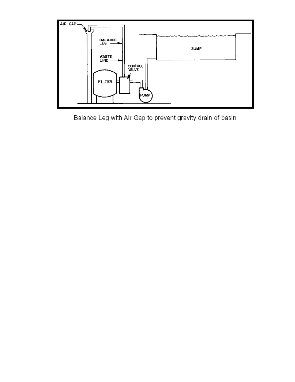
9. Plumb a 2” drain line, be sure to use a siphon break so if the power fails
during a backwash the pump tank does not drain. See Air gap drawing on
page 10
9
10. Plumb the bypass line from the TK SERIES system back to the pump tank see
drawing Page 29
11. Load the sand into the filter vessel. Remove the band clamp from the filter
tank, add enough water to cover the filter laterals, slowly pour the sand in the
vessel 150lbs/TK20, 250lbs TK40, 400lbs TK60and TK80. Clean all sand from
the sealing surface, Make sure the O-ring is in place, set the cover on the filter
vessel place the band on. Tighten the spring nut while GENTLY tapping on the
band clamp to insure uniform tension, DO NOT OVER TIGHTEN
Electrical Connections
All systems are factory prewired and require only field connections to power source.
Proceed as follows:
¾ ALL WIRING CONNECTIONS MUST FOLLOW ALL STATE AND LOCAL
CODES.
A) Check power supply wiring and related components for compatibility with the system
making sure all code requirements are met.
B) Make all contacts according to the appropriate phase/voltage wiring schematic
found within this manual
10
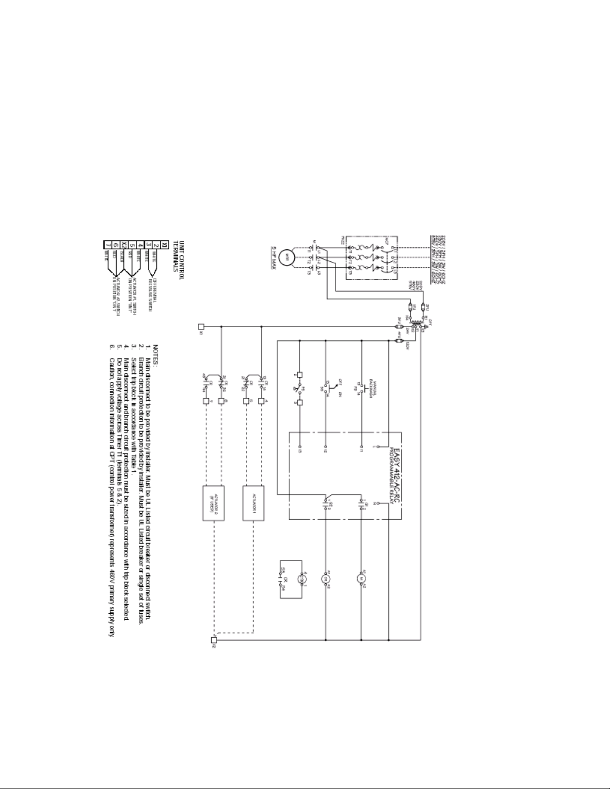
TK SERIES Electrical Drawing
11

TK SERIES
FILTER START UP PROCEDURE
(Flooded Suction Installations)
• Close the reaction column(s) flow control valve(s) and completely open “bypass to
reservoir” valve.
• Place the clear plastic drain hose from the high flow air relief valve, in a drain or
bucket.
• Open the isolation valve from the reservoir. Open high flow air relief valve at the top
of the filter chamber by turning it ¼ turn to its full open position. Allow air to escape
from the filter chamber until water flows from the air relief valve. Close the air relief
valve.
• Check all fittings for leaks.
Note: Insure that the strainer basket is full of water before attempting to start
pump motor. Running the pump without water in the basket will cause failure
of the pump seals.
• Make sure pump on/off switch is in the off position, Turn main disconnect switch to
the on position.
• Turn pump on/off quickly to check for proper pump motor rotation according on the
arrow on the pump. Correct if necessary.
• After verifying pump motor rotation, turn the system panel switch on and allow the
pump to run.
• Open high flow air relief valve once again until you achieve a steady stream of
water. Close the valve.
• Press manual backwash button on the control panel.
The following sequence will occur:
Pump will pause for 30 seconds while the two automatic valves rotate 180°.
Note: Valves must rotate simultaneously in the same direction. If they do
not, check the toggle switches on the valve motor housings to insure that
both switches are in the ON1 position.
Pump will restart and run for 3 minutes. During this time, check the discharge
from the filter to the drain.
Pump will then shut down for 30 seconds while the valves return to the run
position.
After a brief time delay the pump will restart.
Check the backwash counter to insure that the number has increased by one.
• The filter is now operational.
12

WARNING
THE SAND FILTER OPERATES UNDER PRESSURE AND SHOULD NEVER BE OPENED UNTIL THE
PUMP IS SHUT OFF AND THE PRESSURE IS BLED OFF THROUGH THE AIR RELIEF VALVE. NEVER
OPERATE THE SAND FILTER AT PRESSURES OVER 30 PSI. SUCH PRESSURES COULD INDICATE
THE NEED FOR CLEANING OR A MALFUNCTION IN THE SAND BED. THE FILTER SYSTEM IS
DESIGNED TO WITHSTAND WATER TEMPERATURES UP TO 120oF/49oC.
The factory preset time interval for back washing is 12 hrs do not lengthen this
interval without approval of AEC. Failure to comply can result in solidifying
sand.
TK SERIES
REACTION COLUMN START UP PROCEDURE
• With the filter in operation and the bypass open fully, slowly open the reaction
column isolation valve(s) fully followed by the reaction column control valve(s)fully.
• During this initial adjustment, run the flow rate thru the column(s) at the lower portion
of the flow range sticker.
• If the column flow is lower than the lower portion of the flow range sticker slowly
close the bypass valve until the proper flow rate is achieved for each column. The
reaction column control valves may need to be adjusted in multiple column systems
to properly balance the flow.
• Allow the system to operate at this rate for 24 hours. After that time, verify that the
system has backwashed at least 2 additional times, as indicated on the backwash
counter.
• The system is now ready for the full process flow rate. Slowly turn the bypass valve
toward the closed position until the flow is ¾ of the way up the flow range sticker.
On multiple column systems it will be necessary to adjust the reaction column
control valves to properly balance the flow to the individual columns.
• The system is now fully operational.
WARNING
THE REACTION COLUMN(S) OF THIS SYSTEM, EACH HAVE A MAXIMUM RATED FLOW CAPACITY
OF 25 GALLONS PER MINUTE PER COLUMN. OPERATING THE REACTION COLUMN(S) AT A FLOW
RATE GREATER THAN ITS DESIGNED PARAMETERS MAY RESULT IN THE LOSS OF REACTION
MEDIA, AND WILL REDUCE THE SYSTEMS’ EFFICIENCY.
13
 Loading...