

Page 1

Self Cleaning Continuous Filters
Part Number: A0570886
Bulletin Number: WH3-665.2
Effective: 6/11/04
Write Down Your Serial Numbers Here For Future Reference:
_________________________ _________________________
_________________________ _________________________
_________________________ _________________________
We are committed to a continuing program of product improvement.
Specifications, appearance, and dimensions described in this manual are subject to change without notice.
DCN No. ____________
© Copyright 2004
All rights reserved.
Page 2

Please note that our address and phone information has changed.
Please reference this page for updated contact information.
These manuals are obsolete and are provided only for their technical information, data and capacities.
Portions of these manuals detailing procedures or precautions in the operation, inspection, maintenance
and repair of the products may be inadequate, inaccurate, and/or incomplete and shouldn’t be relied
upon. Please contact the ACS Group for more current information about these manuals and their
warnings and precautions.
Parts and Service Department
The ACS Customer Service Group will provide your company with genuine OEM quality parts manufactured to engineering
design specifications, which will maximize your equipment’s performance and efficiency. To assist in expediting your phone
or fax order, please have the model and serial number of your unit when you contact us. A customer replacement parts list
is included in this manual for your convenience. ACS welcomes inquiries on all your parts needs and is dedicated to
providing excellent customer service.
For immediate assistance, please contact:
• North, Central and South America, 8am – 5pm CST +1 (800) 483-3919 for drying, conveying, heating and cooling
and automation. For size reduction: +1 (800) 229-2919.
North America, emergencies after 5pm CST (847) 439-5855
North America email: acsuscanadacustserv@corpemail.com
• Mexico, Central & South America
Email: acslatinamericacustserv@corpemail.com
• Europe, Middle East & Africa +48 22 390 9720
Email: acseuropecustserv@corpemail.com
• India +91 21 35329112
Email: acsindiacustserv@corpemail.com
• Asia/Australia +86 512 8717 1919
Email: acsasiacustserv@corpemail.com
Sales and Contracting Department
Our products are sold by a worldwide network of independent sales representatives. Contact our Sales Department for the
name of the sales representative nearest you.
Let us install your system. The Contract Department offers any or all of these services: project planning; system packages
including drawings; equipment, labor, and construction materials; and union or non-union installations.
For assistance with your sales or system contracting needs please Call:
North, Central and South America +1 (262) 641-8600 or +1 (847) 273-7700 Monday–Friday, 8am–5pm CST
Europe/Middle East/Africa +48 22 390 9720
India +91 21 35329112
Asia/Australia +86 512 8717 1919
Facilities:
ACS offers facilities around the world to service you no matter where you are located. For more information, please visit us at
www.acscorporate.com
United States:
ACS Schaumburg – Corporate Offices
1100 E. Woodfield Road
Suite 588
Schaumburg, IL 60173
Phone: + 1 847 273 7700
Fax: + 1 847 273 7804
ACS New Berlin – Manufacturing Facility
2900 S. 160th Street
New Berlin, WI 53151
Phone : +1 262 641 8600
Fax: + 1 262 641 8653
Asia/Australia:
ACS Suzhou
109 Xingpu Road SIP
Suzhou, China 215126
Phone: + 86 8717 1919
Fax: +86 512 8717 1916
Europe/Middle East/Africa:
ACS Warsaw
Ul. Działkowa 115
02-234 Warszawa
Phone: + 48 22 390 9720
Fax: +48 22 390 9724
India
ACS India
Gat No. 191/1, Sandbhor Complex
Mhalunge, Chakan, Tal Khed,
Dist. Pune 410501, India
Phone: +91 21 35329112
Fax: + 91 20 40147576
Page 3

Shipping Information
Unpacking and Inspection
You should inspect your Self Cleaning Continuous Filter for possible shipping damage.
Thoroughly check the equipment for any damage that might have occurred in transit, such as
broken or loose wiring and components, loose hardware and mounting screws, etc.
In the Event of Shipping Damage
According to the contract terms and conditions of the Carrier, the responsibility of the
Shipper ends at the time and place of shipment.
Notify the transportation company’s local agent if you discover damage.
Hold the damaged goods and packing material for the examining agent’s inspection. Do not
return any goods before the transportation company’s inspection and authorization.
File a claim with the transportation company. Substantiate the claim by referring to the
agent’s report. A certified copy of our invoice is available upon request. The original Bill of
Lading is attached to our original invoice. If the shipment was prepaid, write us for a
receipted transportation bill.
Advise customer service regarding your wish for assistance and to obtain an RMA (return
material authorization) number.
If the Shipment is Not Complete
Check the packing list as back-ordered items are noted on it. You should have:
; Self Cleaning Continuous Filter
; Bill of lading
; Packing list
; Operating and Installation packet
; Electrical schematic and panel layout drawings
; Component instruction manuals
Re-inspect the container and packing material to see if you missed any smaller items during
unpacking.
If the Shipment is Not Correct
If the shipment is not what you ordered, contact the shipping department immediately. For
shipments in the United States and Canada, call 1 (800) 233-4819; for all other countries, call
our international desk at (630) 475-7491. Have the order number and item number available.
Hold the items until you receive shipping instructions.
Self Cleaning Continuous Filters ii
Page 4

Returns
Do not return any damaged or incorrect items until you receive shipping instructions from the
shipping department.
Credit Returns
Prior to the return of any material authorization must be given by the manufacturer. A
RMA number will be assigned for the equipment to be returned.
Reason for requesting the return must be given.
ALL returned material purchased from the manufacturer returned is subject to 15% ($75.00
minimum) restocking charge.
ALL returns are to be shipped prepaid
The invoice number and date or purchase order number and date must be supplied.
No credit will be issued for material that is not within the manufacturer’s warranty period
and/or in new and unused condition, suitable for resale.
Warranty Returns
Prior to the return of any material, authorization must be given by the manufacturer. A
RMA number will be assigned for the equipment to be returned.
Reason for requesting the return must be given.
All returns are to be shipped prepaid
The invoice number and date or purchase order number and date must be supplied.
After inspecting the material, a replacement or credit will be given, at the manufacturer’s
discretion. If the item is found to be defective in materials or workmanship, and it was
manufactured by our company, purchased components are covered under their specific
warranty terms.
.
.
Self Cleaning Continuous Filters iii
Page 5

Table of Contents
CHAPTER 1: SAFETY ................................................................. 6
1-1 How to Use This Manual ............................................................................................. 6
Safety Symbols Used in this Manual.....................................................................6
1-2 Warnings and Precautions .......................................................................................... 7
1-3 Responsibility .............................................................................................................. 8
General Responsibility ..........................................................................................8
Operator Responsibility .........................................................................................9
Maintenance Responsibility................................................................................. 10
Reporting a Safety Defect ................................................................................... 10
CHAPTER 2: FUNCTIONAL DESCRIPTION............................. 11
2-1 Models Covered in This Manual................................................................................11
2-2 General Description................................................................................................... 11
2-3 Standard Features..................................................................................................... 11
Mechanical Features ...........................................................................................11
Electrical Features............................................................................................... 11
Controller Features.............................................................................................. 11
2-4 Options ......................................................................................................................12
2-5 Safety Devices and Interlocks ................................................................................... 12
CHAPTER 3: INSTALLATION ................................................... 14
3-1 Uncrating the Equipment...........................................................................................14
3-2 Mounting the Self Cleaning Continuous Filter ........................................................... 14
Storage................................................................................................................14
Pre-Installation Considerations ...........................................................................15
3-3 Electrical Connections...............................................................................................19
Connecting Solid State Timer Control Panel.......................................................19
3-4 Setup Procedures...................................................................................................... 22
Installing Filter Bags ............................................................................................22
Installing Pressure Gauge ...................................................................................24
Safety Latches..................................................................................................... 25
Installing the Compressed Air Cleaning System ................................................. 26
Completing Mechanical Assembly.......................................................................27
3-5 Initial Start-up ............................................................................................................ 27
Pre-Startup Checks .............................................................................................27
Shutting Down the Collector................................................................................28
CHAPTER 4: OPERATION ........................................................ 29
4-1 Start-up......................................................................................................................29
Standard Start Ups..............................................................................................29
4-2 Self Cleaning Continuous Filter Operation ................................................................ 29
4-3 Shutting Down the Collector......................................................................................30
CHAPTER 5: MAINTENANCE ................................................... 31
5-1 Preventative Maintenance Schedule.........................................................................31
Self Cleaning Continuous Filters iv
Page 6

5-2 Preventative Maintenance.........................................................................................32
Before Entering Dust Collector:...........................................................................32
5-3 Corrective Maintenance ............................................................................................32
CHAPTER 6: TROUBLESHOOTING ......................................... 33
6-1 Introduction................................................................................................................ 33
CHAPTER 7: APPENDIX ........................................................... 37
7-1 Warranty....................................................................................................................37
Warranty Specifications....................................................................................... 37
Warranty Restrictions ..........................................................................................37
Warranty Liabilities ..............................................................................................38
Customer Responsibilities...................................................................................38
7-2 Spare Parts List.........................................................................................................39
7-3 Identification (Serial Number) Tag............................................................................. 40
7-4 Technical Assistance................................................................................................. 40
Parts Department ................................................................................................ 40
Service Department............................................................................................. 40
Sales Department................................................................................................ 40
Contract Department ...........................................................................................40
Self Cleaning Continuous Filters v
Page 7

Chapter 1: Safety
1-1 How to Use This Manual
Use this manual as a guide and reference for installing, operating, and maintaining your Self
Cleaning Continuous Filter. The purpose is to assist you in applying efficient, proven
techniques that enhance equipment productivity.
This manual covers only light corrective maintenance. No other maintenance should be
undertaken without first contacting a service engineer.
The Functional Description section outlines models covered, standard features, and safety
features. Additional sections within the manual provide instructions for installation, preoperational procedures, operation, preventive maintenance, and corrective maintenance.
The Installation chapter includes required data for receiving, unpacking, inspecting, and setup
of the Self Cleaning Continuous Filter. We can also provide the assistance of a factorytrained technician to help train your operator(s) for a nominal charge. This section includes
instructions, checks, and adjustments that should be followed before commencing with
operation of the Self Cleaning Continuous Filter. These instructions are intended to
supplement standard shop procedures performed at shift, daily, and weekly intervals.
The Operation chapter includes a description of electrical and mechanical controls, in
addition to information for operating the filter safely and efficiently.
The Maintenance chapter is intended to serve as a source of detailed assembly and
disassembly instructions for those areas of the equipment requiring service. Preventive
maintenance sections are included to ensure that your continuous filter provides excellent,
long service.
The Troubleshooting chapter serves as a guide for identification of most common problems.
Potential problems are listed, along with possible causes and related solutions.
The Appendix contains technical specifications, drawings, schematics, parts lists, and
available options. A spare parts list with part numbers specific to your machine is provided
with your shipping paperwork package. Refer to this section for a listing of spare parts for
purchase. Have your serial number and model number ready when ordering.
Safety Symbols Used in this Manual
The following safety alert symbols are used to alert you to potential personal injury hazards.
Obey all safety messages that follow these symbols to avoid possible injury or death.
DANGER! DANGER indicates an imminently hazardous situation that, if not avoided,
will result in death or serious injury.
WARNING! WARNING indicates a potentially hazardous situation or practice that, if
not avoided, could result in death or serious injury.
Caution! CAUTION indicates a potentially hazardous situation or practice that, if
not avoided, may result in minor or moderate injury or in property damage.
Self Cleaning Continuous Filter Chapter 1: Safety 6
Page 8
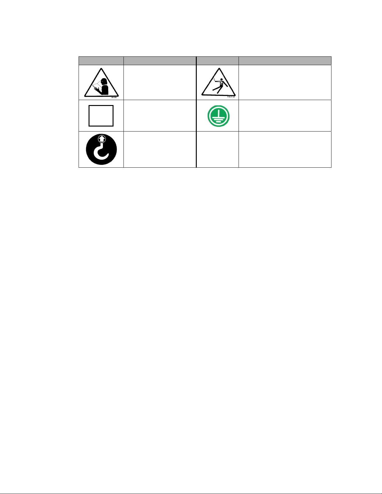
Self Cleaning Continuous Filter Safety Tags
Tag Description Tag Description
Read Operation &
Installation Manual
Protected Earth
PE
Ground
Lifting Point
1-2 Warnings and Precautions
Our equipment is designed to provide safe and reliable operation when installed and operated
within design specifications, following national and local safety codes. This may include, but
is not limited to OSHA, NEC, CSA, SPI, and any other local, national and international
regulations.
To avoid possible personal injury or equipment damage when installing, operating, or
maintaining this equipment, use good judgment and follow these safe practices:
; Read and follow these operation and installation instructions when installing,
operating, and maintaining this equipment. If these instructions become
damaged or unreadable, additional copies are available from the manufacturer.
High Voltage Inside
Enclosure
Earth Ground
; Follow all SAFETY CODES.
; Wear SAFETY GLASSES and WORK GLOVES.
; Work only with approved tools and devices.
; Disconnect and/or lock out power before servicing or maintaining the equipment.
; Use care when LOADING, UNLOADING, RIGGING, or MOVING this
equipment.
; Operate this equipment within design specifications.
; OPEN, TAG, and LOCK ALL DISCONNECTS before working on equipment.
You should remove the fuses and carry them with you.
; Make sure the equipment and components are properly GROUNDED before you
switch on power.
; Use EXTREME CAUTION when working with the Self Cleaning Continuous
Filters. COMBUSTIBLE MATERIALS SHOULD NOT BE MIXED WITH
DUST GENERATED FROM THE GRINDING OF FERROUS METALS.
Static electricity discharge can cause ignition. Inert gas is necessary for some
applications.
Self Cleaning Continuous Filter Chapter 1: Safety 7
Page 9

; When welding or brazing in or around this equipment, make sure VENTILATION is
ADEQUATE. PROTECT adjacent materials from flame or sparks by shielding with
sheet metal. An approved FIRE EXTINGUISHER should be close at hand and
ready for use if needed.
; Do not restore power until you remove all tools, test equipment, etc., and the
equipment and related components are fully reassembled.
; Only PROPERLY TRAINED personnel familiar with the information in this
manual should work on this equipment.
We have long recognized the importance of safety and have designed and manufactured our
equipment with operator safety as a prime consideration. We expect you, as a user, to abide
by the foregoing recommendations in order to make operator safety a reality.
1-3 Responsibility
These machines are constructed for maximum operator safety when used under standard
operating conditions and when recommended instructions are followed in the maintenance
and operation of the machine.
All personnel engaged in the use of the machine should become familiar with its operation as
described in this manual.
Proper operation of the machine promotes safety for the operator and all workers in its
vicinity.
Each individual must take responsibility for observing the prescribed safety rules as outlined.
All warning and danger signs must be observed and obeyed. All actual or potential danger
areas must be reported to your immediate supervisor.
General Responsibility
No mater who you are, safety is important. Owners, operators and maintenance personnel
must realize that every day, safety is a vital part of their jobs.
If your main concern is loss of productivity, remember that production is always affected in a
negative way following an accident. The following are some of the ways that accidents can
affect your production:
• Loss of a skilled operator (temporarily or permanently)
• Breakdown of shop morale
• Costly damage to equipment
• Downtime
An effective safety program is responsible and economically sound.
Organize a safety committee or group, and hold regular meetings. Promote this group from
the management level. Through this group, the safety program can be continually reviewed,
maintained, and improved. Keep minutes or a record of the meetings.
Hold daily equipment inspections in addition to regular maintenance checks. You will keep
your equipment safe for production and exhibit your commitment to safety.
Please read and use this manual as a guide to equipment safety. This manual contains safety
warnings throughout, specific to each function and point of operation.
Self Cleaning Continuous Filter Chapter 1: Safety 8
Page 10

Operator Responsibility
The operator’s responsibility does not end with efficient production. The operator usually has
the most daily contact with the equipment and intimately knows its capabilities and
limitations.
Plant and personnel safety is sometimes forgotten in the desire to meet incentive rates, or
through a casual attitude toward machinery formed over a period of months or years. Your
employer probably has established a set of safety rules in your workplace. Those rules, this
manual, or any other safety information will not keep you from being injured while operating
your equipment.
Learn and always use safe operation. Cooperate with co-workers to promote safe practices.
Immediately report any potentially dangerous situation to your supervisor or appropriate
person.
REMEMBER:
• NEVER place your hands or any part of your body in any dangerous location.
• NEVER operate, service, or adjust the Self Cleaning Continuous Filter without
appropriate training and first reading and understanding this manual.
• NEVER try to pull material out of the Self Cleaning Continuous Filter with your hands
while it is running!
• Before you start the Self Cleaning Continuous Filter check the following:
• Remove all tools from the hopper area;
• Be sure no objects (tools, nuts, bolts, clamps, bars) are laying in the
hopper area;
• If your Self Cleaning Continuous Filter has been inoperative or unattended, check all
settings before starting the unit.
• At the beginning of your shift and after breaks, verify that the controls and other
auxiliary equipment are functioning properly.
• Keep all safety guards in place and in good repair. NEVER attempt to bypass, modify,
or remove safety guards. Such alteration is not only unsafe, but will void the warranty
on your equipment.
• When changing control settings to perform a different mode of operation, be sure
selector switches are correctly positioned. Locking selector switches should only be
adjusted by authorized personnel and the keys removed after setting.
• Report the following occurrences IMMEDIATELY:
• unsafe operation or condition
• unusual Self Cleaning Continuous Filter action
• leakage
• improper maintenance
• NEVER stand or sit where you could slip or stumble into the Self Cleaning
Continuous Filter while working on it.
Self Cleaning Continuous Filter Chapter 1: Safety 9
Page 11

• DO NOT wear loose clothing or jewelry, which can be caught while working on a Self
Cleaning Continuous Filter. In addition, cover or tie back long hair.
• Clean the Self Cleaning Continuous Filter and surrounding area DAILY, and inspect
the machine for loose, missing or broken parts.
• Shut off power to the Self Cleaning Continuous Filter when it is not in use. Turn the
switch to the OFF position, or unplug it from the power source.
Maintenance Responsibility
Proper maintenance is essential to safety. If you are a maintenance worker, you must make
safety a priority to effectively repair and maintain equipment.
Before removing, adjusting, or replacing parts on a machine, remember to turn off all electric
supplies and all accessory equipment at the machine, and disconnect and lockout electrical
power. Attach warning tags to the disconnect switch.
When you need to perform maintenance or repair work on a Self Cleaning Continuous Filter
above floor level, use a solid platform or a hydraulic elevator. The work platform should
have secure footing and a place for tools and parts. DO NOT climb on the Self Cleaning
Continuous Filter, machines, or work from ladders.
If you need to repair a large component, use appropriate handling equipment. Before you use
handling equipment (portable “A” frames, electric boom trucks, fork trucks, overhead cranes)
be sure the load does not exceed the capacity of the handling equipment or cause it to become
unstable.
Carefully test the condition of lifting cables, chains, ropes, slings, and hooks before using
them to lift a load.
Be sure that all non-current carrying parts are correctly connected to earth ground with an
electrical conductor that complies with current codes. Install in accordance with national and
local codes.
When you have completed the repair or maintenance procedure, check your work and remove
your tools, rigging, and handling equipment.
Do not restore power to the Self Cleaning Continuous Filter until all persons are clear of the
area. DO NOT start and run the Self Cleaning Continuous Filter until you are sure all parts
are functioning correctly.
BEFORE you turn the Self Cleaning Continuous Filter over to the operator for production,
verify all guards and safety devices are in place and functioning properly.
Reporting a Safety Defect
If you believe that your equipment has a defect that could cause injury, you should
immediately discontinue its use and inform the manufacturer.
The principle factors that can result in injury are failure to follow proper operating procedures
(i.e. lockout/tagout), or failure to maintain a clean and safe working environment.
Self Cleaning Continuous Filter Chapter 1: Safety 10
Page 12

Chapter 2: Functional Description
2-1 Models Covered in This Manual
This manual provides operation, installation, and maintenance instructions for Self Cleaning
Continuous Filters. Model numbers are listed on the serial tag. Make sure you know the
model and serial number of your equipment before contacting the manufacturer for parts or
service.
Dust collectors filter dust particles quickly and efficiently from process and pneumatic
conveying systems. Self Cleaning Continuous Filter systems are sized to meet the specific
requirements stated by the Customer at the time of purchase.
2-2 General Description
Our Self Cleaning Continuous Filter system is designed to remove 99.9% of dust particles
from your process for thorough air pollution control and product recovery.
2-3 Standard Features
Mechanical Features
• Enamel exterior
• Primed interior
• Legs with adequate clearance for airlock with discharge adapter
Electrical Features
• 115/1/60
• Sensor mounted in receiver side wall for high level cutoff
Controller Features
• NEMA 4 control panel
Self Cleaning Continuous FilterChapter 2: Functional Description 11
Page 13

2-4 Options
Options marked with “*” indicate options that can be factory installed or retrofitted in the
field.
Sprinkler Heads. These are recommended for reducing any potential fire hazard that exists
when the Self Cleaning Continuous Filter is used to collect emissions from steel on combined
metal sandings. They should be installed by licensed contractors who are familiar with the
fire hazards associated with dust control equipment as well as local fire codes.
Pressure Relief Vents. In some applications, these are required. Your insurance company’s
underwriter should be consulted to determine the required vent ratio (if required). To reduce
the probability of a secondary explosion, vents installed inside a building should be vented as
directly as possible to the outside. If equipped with pressure relief vents, the Self Cleaning
Continuous Filter should be installed so that the vents are unobstructed by ladders, walkways
or other structures.
High Temperature Process Air Equipment. Standard Self Cleaning Process Air Filters are
designed for ambient air conditions. If higher operating temperatures are required, this
equipment is available.
2-5 Safety Devices and Interlocks
This section includes information on safety devices and procedures that are inherent to the
Self Cleaning Continuous Filter. This manual is not intended to supersede or alter safety
standards established by the user of this equipment. Instead, the material contained in this
section is recommended to supplement these procedures in order to provide a safer working
environment.
At the completion of this section, the operator and maintenance personnel will be able to do
the following:
• Identify and locate specific safety devices.
• Understand the proper use of the safety devices provided.
• Describe the function of the safety device.
Safety Circuit Standards
Safety circuits used in industrial systems protect the operator and maintenance personnel
from dangerous energy. They also provide a means of locking out or isolating the energy for
servicing equipment.
Various agencies have contributed to the establishment of safety standards that apply to the
design and manufacture of automated equipment. The Occupational Safety and Health
Administration (OSHA) and the Joint Industrial council (JIC) are just a few of the
organizations that have joined with the plastics industry to develop safety standards.
Every effort has been made to incorporate these standards into the design of the Self Cleaning
Continuous Filter; however, it is the responsibility of the personnel operating and maintaining
the equipment to familiarize themselves with the safety procedures and the proper use of any
safety devices.
Self Cleaning Continuous Filter Chapter 2: Functional Description 12
Page 14

Fail Safe Operation
If a safety device or circuit should fail, the design must be such that the failure causes a
“Safe” condition. As an example, a safety switch must be a normally open switch. The switch
must be held closed with the device it is to protect. If the switch fails, it will go to the open
condition, tripping out the safety circuit.
At no time should the safety device fail and allow the operation to continue. For
example, if a safety switch is guarding a motor, and the safety switch fails, the motor should
not be able to run.
Safety Device Lock-Outs
Some safety devices disconnect electrical energy from a circuit. The safety devices that are
used on these Self Cleaning Continuous Filters are primarily concerned with electrical power
disconnection and the disabling of moving parts that may need to be accessed during the
normal operation of the machine.
Some of the safety devices utilize a manual activator. This is the method of initiating the
safety lock out. This may be in the form of a plug, lever or a handle. Within this lockable
handle, there may be a location for a padlock. Personnel servicing the equipment should
place a padlock in the lockout handle.
In addition to the safety devices listed above, these Self Cleaning Continuous Filters are
equipped with a line cord plug. This allows the operator or maintenance personnel to unplug
the Self Cleaning Continuous Filter from its power source and tag it out. The plug can then
be tagged with any number of approved electrical lockout tags available at most electrical
supply stores.
WARNING! Always disconnect and lockout all electrical power and pneumatic (i.e. compressed air)
sources prior to servicing or cleaning the Self Cleaning Continuous Filter. Failure to do
so may result in serious injury. No one but the person who installed the lockout may
remove it.
Self Cleaning Continuous Filter Chapter 2: Functional Description 13
Page 15

Chapter 3: Installation
3-1 Uncrating the Equipment
Self Cleaning Continuous Filters are shipped mounted on a skid, enclosed in a plastic
wrapper, and contained in a cardboard box.
1. Pry the crating away from the skid.
Note: Remove the nails holding the box to the skid and lift the box off
carefully; avoiding staples in the 1’ x 4’ wood supports. Cut the steel
banding.
2. Use a pry bar to remove the blocks securing the unit to the skid.
3. Lift unit from sides, inserting forklift under the base. The forks must be
equidistant from the centerline of the unit and the unit must be balanced
on the forks. Lift slowly and only high enough to clear the skid. Use a
pry bar if necessary to carefully remove the skid from the unit.
4. Lower slowly.
5. Temporary hardware has been installed to prevent side panels from
shifting in transit. Remove hardware.
6. Retain the crating material for reshipping the components in case hidden
shipping damage is found.
3-2 Mounting the Self Cleaning Continuous Filter
The Self Cleaning Continuous Filter collector has been designed to minimize customer
assembly. Air headers, solenoids, air piping and air pressure gauges are all shipped mounted
on the collectors, completely piped for operation.
Housings for the collectors are shipped as completely welded assemblies. Larger rectangular
collectors are shipped in two subassemblies. The hopper is often inverted and nested inside
the main housing. Walk-in plenums for top bag removal collectors are shipped as a separate
subassembly.
Timers, bags, bag clamps, cages and differential pressure gauges are shipped separate from
the collector. These shipments are carefully marked for identification. For specific
installation procedures, follow the instructions provided below.
Storage
If unit is not to be installed for a considerable amount of time, all filter tubes should be stored
in a warm, dry, rodent-proof location. The Self Cleaning Continuous Filter unit and the tube
cages should be stored in a dry area if available. If not, all openings should be covered to
protect interior surfaces from corrosion.
Self Cleaning Continuous Filter Chapter 3: Installation 14
Page 16

Pre-Installation Considerations
Note: Installation crews should always consist of a minimum of two (2) persons.
Personnel should NEVER be allowed to work inside the collector alone.
Your unit is usually mounted on a reinforced concrete foundation. Roof mounting is also
possible. Factors to be considered prior to installation are the weight of the Self Cleaning
Continuous Filter, snow loads, full hopper loads and wind loads.
The installation site should be clear of obstructions such as utility lines and overhanging
roofs. Ample space should be available for the operation of a crane during assembly.
Note: The caulking, nuts, bolts, washers and the pressure differential gauge are
shipped in one box with the installation instructions.
Assembling Main Housing
1. Set support frame legs in place and secure with anchor bolts (See Figure 1 below.).
2. Connect cross bracing to support frame legs (See Figure 1)
Note: All bolts should be installed loosely until each subassembly is complete. After
frame is square and legs are plumb, tighten all bolts securely.
Figure 1: Self Cleaning Continuous Filter Support Frame Legs
Note: Drawing may not depict current unit. Contact manufacturer’s
engineering department for current drawings.
Self Cleaning Continuous Filter Chapter 3: Installation 15
Page 17

Note: Lifting lugs and spreader bar should be used for lifting Self Cleaning
Continuous Filter sections (See Figure 2 below).
Figure 2: Self Cleaning Continuous Filter Lifting Diagram
Note: Drawing may not depict current unit. Contact manufacturer’s
engineering department for current drawings.
3. Set hopper in place on support frame so that the inlet section is properly oriented with
respect to the inlet ductwork, and bolt hopper brackets to the support frame (See
Figure 3 on the next page). Apply two (2) beads of furnished caulking to the top
flange on the hopper (See Figure 4).
Self Cleaning Continuous Filter Chapter 3: Installation 16
Page 18

Figure 3: Installing hopper in support frame
Note: Drawing may not depict current unit. Contact manufacturer’s
engineering department for current drawings.
Figure 4: Sealing hopper flange
Note: Drawing may not depict current unit. Contact manufacturer’s
engineering department for current drawings.
Self Cleaning Continuous Filter Chapter 3: Installation 17
Page 19

4. Lift the main housing section, rotate the outlet to the proper orientation with respect
to the outer ductwork, set the bottom flange of the housing in place on the top flange
of the hopper, and bolt the two flanges together (See Figure 5 below). Apply two
beads of furnished caulking to the top flange on the housing in the same manner as
step number 3.
Figure 5: Assembling Main Housing Sections
Note: Drawing may not depict current unit. Contact manufacturer’s
engineering department for current drawings.
Self Cleaning Continuous Filter Chapter 3: Installation 18
Page 20

3-3 Electrical Connections
Our Self Cleaning Continuous Filter systems come pre-wired and are ready to operate. They
are configured for 115/1/60 voltage and require a suitable grounded plug for use with a
grounded duplex receptacle.
Refer to the electrical diagrams enclosed in the Operation and Installation packet included
with your unit for specific wiring instructions.
Connecting Solid State Timer Control Panel
1. The timer is a completely solid state switching unit manufactured to rigid
specifications. The timer is capable of switching up to 10 outputs at 1 amp each with
115 volts line input. Each output is capable of handling one solenoid on each air
header and can handle up to six headers for a total of sixty solenoids, i.e. sixty rows
of filter bags per timer.
2. The timing range is fully adjustable for optimum collector performance. The “ON
TIME” (pulse duration) is adjustable from 0.05 seconds to 0.5 seconds. The “OFF
TIME” (interval between pulses) can be varied from 1.5 to 30 seconds. An indicator
light for “power on” is prominently located on the board as well as lights which
indicate which row of bags is being cleaned. If desired, the timer can be activated by
an external differential pressure switch. In this arrangement the cleaning cycle would
be used only when it is necessary, as determined by a preset pressure drop across the
tubesheet.
3. The standard timer is shipped in a NEMA 4, weatherproof enclosure for mounting by
the customer. Other enclosures are available for hazardous applications.
4. If the timer is to be mounted on the collector, vibration mounts should be provided.
It is more desirable to mount the timer away from the collector in an accessible
location that is free from vibration. The timer should not be exposed to temperatures
over 120°F.
5. Install an “ON-OFF” switch in the power supply to the timer. Connect 115 volt,
single phase, 60 Hz, 10 amperes input through this switch to timer terminals marked
“Line L1” and “L2.” In grounded systems connect neutral of line to “L2.”
6. Connect wiring between the timer and solenoid valves; one side of each solenoid to
the timer common terminal marked “SOL COM.”, and the other side of the first
solenoid to the timer output marked “Solenoids 1”, the second solenoid to “Solenoids
2”, etc.
7. The black program wire in the timer should be connected to the “COMPARTMENT
USED” socket number which is the same number as the highest numbered
“Solenoids” terminal which is used. For example: if eight solenoids are connected to
the timer, the program wire should be connected to the number 8 “COMPARTMENT
USED” socket.
Self Cleaning Continuous Filter Chapter 3: Installation 19
Page 21

8. On collectors with more than one air header, one wire from each solenoid is
connected to the timer marked “SOL COM.” The other wire from the first valve on
each header should be connected to the timer terminal marked “Solenoids 1”, the
second valve on each header to “Solenoids 2”, etc. On certain collectors the number
of solenoid valves on each header differ. For example: a collector may have a total
of 26 valves with three air headers. Two would have 9 valves, the third 8. The
solenoids would be connected in sequence to the timer, with three wires on positions
one through eight. On the ninth post there would be only two solenoid wires. The
program wire would be connected to the ninth “COMPARTMENT USED” socket.
Self Cleaning Continuous Filter Chapter 3: Installation 20
Page 22

Figure 6: Timer Control Connections
Self Cleaning Continuous Filter Chapter 3: Installation 21
Page 23

3-4 Setup Procedures
This section provides the procedures necessary for configuring your Self Cleaning Continuos
Filter system.
Configuration of your Self Cleaning Continuos Filter system includes installing the Filter
bags and differential pressure gauge, adjusting the safety latches on the hopper door, making
compressed air connections and running the necessary ductwork. We recommend that you
carry out these procedures in the order given here.
Note: Before carrying out these procedures, install all equipment as described in this
section.
Installing Filter Bags
Side Bag Removal Collectors
1. Slip filter bag over the cage, making sure that the bag seam is not over the split in the
top collar of cage. (See Fig. 7 on the next page.)
2. Bottom of bag must be tight against the cage bottom, the seam should be straight and
all wrinkles smoothed out.
3. Fold the top of the bag (about two inches) over the top of the cage, smooth out the
inside folds, and make sure that the bag does not overlap the annular groove on inside
of cage (trim off excess bag length if necessary). (See Fig. 8 on the next page.)
4. Slip on the bag clamp (loosely). The tightening mechanism should not be over the
bag seam. (See Fig. 9 on the next page.)
5. Slide the bag and cage upward over the bag cup until the cage snaps into place on the
groove in the bag cup. Bag and cage assembly should fit tight against tubesheet for
proper alignment. (See Fig. 10 on the next page.)
6. Tighten the bag clamp. It is important that a 3/8” socket be used: a screwdriver may
slip and puncture the bag. (See Fig. 11 on the next page.)
7. Check to make sure that bags are hanging straight and do not touch other bags or the
collector housing. (See Fig. 12 on the next page.)
8. Install the remaining bags in the same manner.
9. Close and tighten all access doors.
Self Cleaning Continuous Filter Chapter 3: Installation 22
Page 24

FIG. 7
FIG. 8
FIG. 9
FIG. 10
FIG. 11
FIG. 12
Top Bag Removal Collectors
1. From the top side of the tubesheet, lower the bag into the housing up to the bag cuff.
2. The bag cuff has two sewn-in steel bands. Collapse the cuff into a U-shape and
lower the bag until one of the bands is below the tubesheet and one above. Then let
the cuff spring back to its original shape. Smooth the cuff around the hole. The cuff
should form a perfect seal at the tubesheet.
3. Lower the cage assembly into the bag and press firmly into place.
4. Install the remaining bags in the same manner.
5. Locate a blowpipe over each row of bags and connect each blowpipe to the air header
by slipping the blowpipe into the coupling at the collector wall and tightening the
collar.
6. Close and tighten all access doors.
Self Cleaning Continuous Filter Chapter 3: Installation 23
Page 25

Installing Pressure Gauge
1. Install the differential pressure gauge according to the detailed instruction sheet
packed in the box with your gauge.
2. Mount the gauge in a location that is free from excessive vibration and where the
temperature does not exceed 140°F. Avoid direct sunlight.
3. For permanent installations, it is recommended that ¼” O.D. copper tubing be used
with regular compression fittings. An in-line paper filter will prevent dust from
getting into the gauge line. If this is not used, it is recommended that a loop be
placed in the high pressure gauge line that leads from the dirty air housing so that
dust does not enter the gauge.
4. Adjust the differential pressure gauge to indicate zero.
Figure 13: Connecting Differential Pressure Gauge
Note: Drawing may not depict current unit. Contact manufacturer’s
engineering department for current drawings.
Self Cleaning Continuous Filter Chapter 3: Installation 24
Page 26

Safety Latches
Due to the extreme pressure that your unit operates under, it has been equipped with safety
latches on the door. These latches require specific amounts of pressure and turns (shown in
the tables below) to undo them.
Release Pressure (Lbs.) Pressure Per Turn
Minimum Maximum
43 180
5.96 2.98 23
Change (Lbs.)
Per ½ Turn
Full Turns
Available
• For negative systems, each latch must be set at “0” turns for minimum release pressure
(43 lbs.). With three (3) latches per door, the total force required to open the door is
129 lbs. (40 lbs./sq. ft.)
• For positive systems, each latch must be set to open just above operating pressure (See
table below).
Pressure at SCF
Inlet (in. Wg.)
Over Up To Turns From Loosest Position Turns Off of Tightest Position
50 23
56 1 22
67 2 21
78 3 20
89 4 19
910 5 18
10 11 6 17
11 12 6-1/2 16-1/2
12 13 7-1/2 15-1/2
13 14 8-1/2 14-1/2
14 15 9-1/2 13-1/2
15 16 10-1/2 12-1/2
16 17 11-1/2 11-1/2
Column 1 Column 2
To adjust the latch, place it in the door closed position. When in this position, one rivet
which holds the laminated cam together is exposed.
Adjusting Unmounted Latches
1. Turn the adjusting screw (Shown in Figure 9 below) counter-clockwise to its lowest
position, making sure that the square nut does not come off the ball pin.
Figure 14: Safety Latch Components
2. Tighten the adjusting screw until the desired pressure setting is reached (See Column
1 in the Table above for pressure setting).
Self Cleaning Continuous Filter Chapter 3: Installation 25
Page 27

Adjusting Mounted Latches
Adjustment should be made by turning the adjustment screw to its tightest position and
backing off to the desired setting (See Column 2 above).
It should be possible to feel the adjusting screw slipping into the relaxed position at each half
turn.
Installing the Compressed Air Cleaning System
Air Consumption
The average amount of air that is consumed is listed on the drawing for each collector. This
is based on a six second pulse interval, “OFF-TIME”, and a pulse duration of 0.05 seconds,
“ON TIME”, which are average settings for most applications and can be varied up or down
depending on the type of dust and dust loading. For example with a very light dust loading,
the “OFF TIME” could be set at 12 to 18 seconds thus reducing the air requirements to ½ or
1/3 of the stated volume. A corresponding reduction in the size of the air supply piping may
be made.
Air Supply Piping
A 1” to 2-1/2” O.D. compressed air supply pipe furnishing 85 to 100 psig air (whether all or
no other equipment on the same line is used) should be connected to the air header. Refer to
Figure 15 below for recommended pipe sizes. Higher pressures shorten bag life, lower
pressures do not adequately clean the filter bags. It is a good practice to blow down the air
supply piping before connecting it to the air header. This removes any debris in the supply
pipe before it is connected to your collector.
Figure 15: Recommended Pipe Sizes
Total Free Air
Consumption
Up to 50 SCFM 1” O.D. 1-1/4” O.D. 1-1/4” O.D.
51 to 100 SCFM 1-1/4” O.D. 1-1/2” O.D. 2” O.D.
101 to 200 SCFM 1-1/2” O.D. 2” O.D. 2-1/2” O.D.
Air Quality
Dirt, scale or foreign matter in the piping can cause problems of the air pulsing system. Oil
in the air supply can eventually cause plugging of the bags. Water in the system can cause
valve problems, plus the chance of freeze-up in a cold atmosphere. It is therefore, necessary
that the air be clean, dry and oil-free. The air receiver should have an automatic moisture
drain. In-line air filters with automatic drains may suffice if moisture content is not too great
and if kept from freezing. However, if a large amount of moisture or oil is present, a
desiccant-type filter is recommended.
Up to 100 Ft. Up to 500 Ft. Up to 1,000 Ft.
Self Cleaning Continuous Filter Chapter 3: Installation 26
Page 28

Completing Mechanical Assembly
1. Connect duct work (as required) to the Self Cleaning Continuous Filter inlet and
outlet.
WARNING! Burning objects, such as lighted cigarettes, should not be put into the hood
or inlet ducting to the Self Cleaning Continuous Filter.
2. Connect discharge device to the hopper outlet.
Caution! The Self Cleaning Continuous Filter system is not intended for material
storage. Provision should be made for continuous hopper discharge while
maintaining the air seal.
3-5 Initial Start-up
WARNING! The crew chief or foreman should make a final inspection of the collector
internals and account for all personnel prior to activation of the
equipment.
Note: Failure to adhere to the following procedures could result in poor performance
of or damage to the Self Cleaning Continuous Filter unit or injury to
personnel.
Pre-Startup Checks
Auxiliary Equipment
1. Inspect all equipment before start-up to see that there are no foreign objects in
rotating equipment and that safety equipment is in place.
2. Start the fan, screw conveyor and/or airlock and inspect for proper rotation and that
all equipment runs smoothly. After making the necessary corrections, turn all this
equipment off.
Ductwork
See that all connections are tight and that all cleanout ports are closed. The ductwork must be
free of debris.
Starting the System
1. All doors and ports should be closed, with timer and auxiliary equipment off. Turn
on compressed air to collector and inspect the system for leaks. If air is leaking from
any blowpipe with the timer off, there may be a leak between its solenoid and
diaphragm valve. Inspect the ¼” O.D. tubing between the solenoids and diaphragm
valves to be certain that all connections are tight and there are no leaks. The tubing
must not be crimped. Shut off the compressed air supply.
2. Turn on the timer. The red “power on” indicator should light. Turn “OFF TIME”
and “ON TIME” knobs fully counterclockwise. The individual timing lights should
blink at 1.5 second intervals and the corresponding solenoid valves will be activated
(audible).
3. Turn on the air supply to the air header. All solenoid valves should be operating and
the exhaust air from each valve can be felt. Let the collector pulse for ten minutes to
clear all lines then set “OFF” time to between six to ten seconds with 85 psig air
supplied. Later this may be adjusted to suit your collection requirements based on
the dust loading.
Self Cleaning Continuous Filter Chapter 3: Installation 27
Page 29

4. Turn on all dust discharge equipment such as rotary valves, screw conveyors, etc.
Note: A small amount of dust emission may occur during initial start-up, but should
cease after a few hours of operation. If emission continues, inspect the bags
for proper installation.
5. If water vapor or other condensables are present, it will be necessary to preheat the
system so that the surface temperature of the piping and collector are above the dew
point. Dryers, coolers and some grinding systems are common examples.
Note: When the Self Cleaning Continuous Filter is started in cold weather,
condensation may form on the filter tubes and inside surfaces of the housing.
To avoid condensation problems, allow the main system fan to operate
approximately twenty (20) minutes with clean air before allowing materials or
contaminants to enter the air system. At shutdown, allow the timer to operate
thirty (30) minutes after shutting down the main system fan.
6. Start the fan with the fan damper set at about half-flow and run for 30 minutes
because it is good practice to introduce the dust stream to a new bag at a reduced rate.
This is particularly true when very fine solids (less than 2 microns) or high
concentrations are present.
Caution! It is possible to overload the system fan motor during initial start-up. If
motor amperage is excessive, reduce air flow until pressure loss on the Self
Cleaning Continuous Filter stabilizes.
7. Observe the differential pressure gauge. At start-up, the pressure drop will be low.
After 30 minutes of operation the bags will start to be coated, the filtering efficiency
will increase and the pressure differential will start to rise. Then the main fan damper
should be opened to the design setting.
8. When the collector has stabilized (may require eight hours) the differential pressure
should remain steady at some value between 1” and 6” W.G. If it is below 4”
gradually increase the “OFF” time until it reaches 4” W.G. If it is over 4” the “OFF”
time should be decreased until it reaches 4” W.G.
9. Temperature of the system must be controlled to remain below the maximum
temperature capability of the filter bags.
10. The collector is now ready for use.
Shutting Down the Collector
Dust Control and Pneumatic Conveying Systems
1. Turn off the main fan.
2. Wait five to ten minutes and turn off the timer and discharge (auxiliary) equipment.
3. Turn off the compressed air.
Process System
1. Dryers and the system to the collector discharge should be run until empty and heat
maintained at a reduced rate until the collector metal surfaces and filter bags are dry.
2. Perform steps 1 through 3 listed above in the Dust Control and Pneumatic Conveying
System section.
Self Cleaning Continuous Filter Chapter 3: Installation 28
Page 30

Chapter 4: Operation
4-1 Start-up
Standard Start Ups
Note: When new bags are installed, follow the Initial System Start Up Procedure on
the previous pages. Subsequent start ups should begin with all systems off.
Activate the Self Cleaning Continuous Filter in the following sequence:
1. Verify that all filter bags have been installed, all ports, access doors and rotating
equipment (belt guards, etc.) are in place.
2. Turn on the compressed air.
3. After pressure reaches a minimum of 85 psig, turn on the timer.
4. Turn on all of the dust discharge equipment.
5. Turn on the main fan. Preheat the system if necessary.
6. This equipment has been designed to filter 99.9% of dust particles. If the collector
discharge is visible, refer to the Troubleshooting section of this manual.
4-2 Self Cleaning Continuous Filter Operation
When the unit has been activated, the following sequence of events occurs:
Dust-laden air enters the hopper where heavier particles drop out of the air stream. Lighter
particles are trapped in the air stream and rise.
As air passes through the filter bags, dust particles are collected on the outside surface of the
filter bags and the cleaned air is exhausted from the collector.
At precise intervals, jets of high pressure air pass through the venturis, inducing a strong flow
of secondary air, briefly reversing the air flow through the bags.
Shock waves pass down the inside of the bags, flexing the bags outward. The reversed air
flow dislodges accumulated dust from the bag and the dust drops into the hopper.
With this method of cleaning, airflow through a row of bags is reversed for only a fraction of
a second, resulting in steady airflow through the collector. The system is therefore
maintained at steady-state conditions.
Collection operation is controlled by an easily-adjusted solid state timer. A Magnahelic
gauge permits optimum regulation of the timer. Pulse durations and pulse intervals can be
simply and accurately set at the timer to minimize air consumption. See Figure 16 for a
diagram of the process air flow through the collector.
Self Cleaning Continuous Filter Chapter 4: Operation 29
Page 31

Figure 16: Collector Process Air Flow
4-3 Shutting Down the Collector
Dust Control and Pneumatic Conveying Systems
1. Turn off the main fan.
2. Wait five to ten minutes and turn off the timer and discharge (auxiliary) equipment.
3. Turn off the compressed air.
Process System
1. Dryers and the system to the collector discharge should be run until empty and heat
maintained at a reduced rate until the collector metal surfaces and filter bags are dry.
2. Perform steps 1 through 3 listed above in the Dust Control and Pneumatic Conveying
System section.
Self Cleaning Continuous Filter Chapter 4: Operation 30
Page 32

Chapter 5: Maintenance
5-1 Preventative Maintenance Schedule
The items below should be inspected and/or replaced to keep your Self Cleaning Continuous
Filter operating at peak efficiency. Frequency will vary widely with different operating
conditions. Perform each inspection at the regular intervals listed below.
System model # Serial #
Daily
Adjust timer “OFF”
time to achieve a
differential
pressure of 4” W.G.
Every week
Check timer and
solenoid valves for
proper operation.
Date/ByDate/ByDate/ByDate/ByDate/ByDate/ByDate/ByDate/ByDate/ByDate/ByDate/ByDate/ByDate/
Date/ByDate/ByDate/ByDate/ByDate/ByDate/ByDate/ByDate/ByDate/ByDate/ByDate/ByDate/ByDate/
➀
➀ Usually listening to determine that there is a uniform time interval between solenoid air discharge blasts will suffice.
Every month Jan Feb Mar Apr May Jun Jul Aug Sep Oct Nov Dec
Lubricate fan,
rotary valve and
screw conveyor.
Inspect seals on
latter two for dust
loss.
Quarterly 1 2 3 4
Inspect filter bags
for condition and
that every bag
clamp is tight.
Note: Inspect, clean and replace air supply and differential filters as operating
conditions require.
By
By
- Photocopy this page for your maintenance records -
Self Cleaning Continuous Filter Chapter 5: Maintenance 31
Page 33

5-2 Preventative Maintenance
This section describes maintenance procedures which will increase the longevity and
efficiency of your Self Cleaning Continuous Filter.
Perform the items listed on the previous page at the recommended intervals.
Before Entering Dust Collector:
1. Run cleaning mechanism 20 minutes with fan off to clean the filter bags.
2. Run solids out of the hopper.
3. Lock out electrical power on all rotating equipment.
4. If toxic gases and/or solids are present, purge collector housing and block off inlet
duct.
5. Install catwalks and safety cables.
6. Secure access doors in open position or remove doors by lifting from the hinge pins.
7. Use the buddy system.
8. Wear a respirator.
5-3 Corrective Maintenance
This section provides you with the information necessary to correct or repair any issues
which might appear during the normal operation of your Self Cleaning Continuous Filter.
Although we have listed how to perform these procedures, it is recommended that you call
the Service Department to have any in-depth maintenance performed.
1. Replace damaged wiring.
2. Replace any pulse valve control or pressure gauge tubing which has been kinked or
damaged.
Note: When replacing pulse valve control tubing, make sure that all tubes are of
equal length.
Self Cleaning Continuous Filter Chapter 5: Maintenance 32
Page 34

Chapter 6: Troubleshooting
6-1 Introduction
The utmost in safety precautions should be observed at all times when working on or around
the machine and the electrical components. All normal trouble-shooting must be
accomplished with the power off, line fuses removed, and with the machine tagged as out of
service.
The use of good quality test equipment cannot be over-emphasized when troubleshooting is
indicated. Use a good ammeter that can measure at least twice the AC and DC current that
can be encountered for the machine. Be sure that the voltmeter has at least minimum
impedance of 5,000 OHMS-per-volt on AC and 20,000 OHMS-per-volt on DC scales.
Popular combination meters, VOM and VTVM can be selected to provide the necessary
functions.
Before making haphazard substitutions and repairs when defective electrical components are
malfunctioning, we recommend that you check the associated circuitry and assemblies for
other defective devices. It is common to replace the obviously damaged component without
actually locating the real cause of the trouble. Such hasty substitutions will only destroy the
new component. Refer to wiring diagrams and schematics.
Locating mechanical problems, should they occur, is relatively straightforward. When
necessary, refer to the parts catalog section.
Problem Possible cause Corrective action
1. Visible exhaust dust loss.
2. Insufficient air pressure.
Missing bag, dust loss will be
constant not in synchronization
with valve blasts.
Improperly installed bags.
Loose clamps or bag tops not
clamped between cages and
venturi collars. Constant dust
loss.
Holes in bags from mechanical
damage during installation,
abrasion, thermal or corrosive
attack or wear. Generally in
synchronization with valve
blasts.
Dust in plenum after bags fail.
Piping leaks. Tighten fittings.
Additional usage from plant
system.
Locate and replace missing
bags.
Reinstall bags and cages
properly.
Replace worn or damaged bags
with bags made from filter
medium suitable for application.
Plugging venturis with 3”
diameter rubber plugs from the
clean air (plenum) side of the
collector is a quick temporary
measure until the bags can be
replaced.
Always clean plenum before
installing new bags.
Revise system to furnish
adequate air supply.
Self Cleaning Continuous Filter Chapter 6: Troubleshooting 33
Page 35

Problem Possible cause Corrective action
Debris in diaphragm valve. Remove debris.
3.Entire row of bags
inadequately cleaned.
4. Random bag inadequately
cleaned.
5. High differential pressure.
Dirt in solenoid plunger.
Solenoid valve inoperative.
Electric, solenoid, or timer fault.
Debris in air distribution pipe
hole.
Excessive air flow.
Compressed air pressure below
75 psig.
Solenoids skipping.
Reverse leakage through the
rotary valve.
Dust on inside of bags after
previous bag failure.
Blinding (purging) of bags due
to condensables.
Re-entrainment of dust due to
hopper overloading, bridging, or
plugging.
Improper timer sequence.
Remove solenoid cover and
clean.
Establish power to solenoid and
proper wiring to timer. Check
solenoid and if O.K. change
wiring at timer to next unused
terminal and move program
wire to highest numbered
terminal used or replace timer.
If solenoid defective, replace.
Remove debris.
Adjust fan damper until
pressure gauge indicates proper
pressure.
See Problem #2 on the previous
page.
Establish power to solenoid and
proper wiring to timer. Check
solenoid and if O.K. change
wiring at timer to next unused
terminal and move program
wire to highest numbered
terminal used or replace timer.
If solenoid defective, replace.
Check the rotary valve for wear
or damage and correct.
Clean plenum and inside of
bags.
Always clean plenum before
installing new bags.
Change operations upstream so
that liquids remain vaporized
through unit. May be necessary
to insulate the collector.
Usually operating the collector
with no solids flowing through
will permit recovery.
Run out dust from discharge
system with main fan off,
consider increasing capacity of
discharge system or reducing
load and consider installing
hopper vibrators.
Inspect timer for proper
solenoid wiring and program
wire position.
Self Cleaning Continuous Filter Chapter 6: Troubleshooting 34
Page 36

Problem Possible cause Corrective action
Return timer to us for repair or
replace.
If bags were cleaned, they may
have shrunk and are too tight to
permit proper flexing. Replace
bags.
Establish power to solenoid and
proper wiring to timer. Check
solenoid and if O.K. change
wiring at timer to next unused
terminal and move program
wire to highest numbered
terminal used or replace timer.
If solenoid defective, replace.
Remove debris in diaphragm
valve.
Remove solenoid valve cover
and clean.
Leak in tubing between
solenoid and diaphragm valves.
See possible causes &
corrective actions for problems
2, 3, and 5.
Stop leaks.
Use proper shutdown
procedure. Inspect piping for
foreign material and remove.
Bags should feel soft to the
hand or be replaced.
Establish power to solenoid and
proper wiring to timer. Check
solenoid and if O.K. change
wiring at timer to next unused
terminal and move program
wire to highest numbered
terminal used or replace timer.
If solenoid defective, replace.
5. High differential pressure.
Cont’d.
6. Improper pulsing.
7. Insufficient dust collection.
(System volume too low)
Defective timer.
Bags too tight.
Solenoid valves not working.
Continuous air flow through
diaphragm valve.
Fan running backwards. Correct fan rotation.
High differential pressure.
Fan belt slippage. Tighten or replace belts.
Air short-circuiting between
collection point(s) and fan.
Additions to system. Increase system capacity.
System blockage.
See possible causes & corrective
actions for problem 5.
Self Cleaning Continuous Filter Chapter 6: Troubleshooting 35
Page 37

Problem Possible cause Corrective action
Bleed in ambient air and/or
8. Short bag life.
9. Timer malfunction.
10. Unusual differential pressure
gauge readings.
High temperature.
Chemical attack. Contact us for recommendation.
Localized wear from rubbing.
“Power on” indicator light not
on.
Solenoids skipping.
Unusual readings.
Blocked gauge tubing.
replace with bags of high
temperature rated fabric.
Straighten cages so that bags do
not rub against each other or the
collector housing. Replace bags
and corroded or broken cages.
Wear at air inlet may require an
inlet baffle.
Ascertain that timer “ON-OFF”
switch is on, that timer wiring is
connected, and that indicator
bulb is good. Inspect for blown
fuse. Replace with 3 amp., 3
AG fuse. Do not use slow blow
type.
Establish power to solenoid and
proper wiring to timer. Check
solenoid and if O.K. change
wiring at timer to next unused
terminal and move program
wire to highest numbered
terminal used or replace timer.
If solenoid defective, replace.
Inspect gauge filter, replace if
plugged.
Disconnect and remove
blockage. If blockage occurs
frequently, install filter and
replace it routinely.
Self Cleaning Continuous Filter Chapter 6: Troubleshooting 36
Page 38

Chapter 7: Appendix
7-1 Warranty
Unless otherwise specified, this product includes a Standard ONE YEAR PARTS AND
LABOR WARRANTY.
Warranty Specifications
The manufacturer hereby expressly warrants all equipment manufactured by it to be free from
defects in workmanship and material when used under recommended conditions, as set forth
in the operating manuals for such equipment. THE FOREGOING EXPRESS WARRANTY
IS EXCLUSIVE AND IN LIEU OF ALL OTHER WARRANTIES, GUARANTEES,
AGREEMENTS, AND SIMILAR OBLIGATIONS OF THE COMPANY AND/OR
MANUFACTURER (UNLESS OTHERWISE SPECIFIED IN THE SPECIFIC PRICE
PAGE OR LIMITED BY THE MANUFACTURERS’ WARRANTY FOR PARTS). The
Company’s obligation is limited to repair or replace FOB the factory any parts that are
returned, prepaid, within one year of equipment shipment to the original purchaser, and
which in the Company’s opinion, are defective. Any replacement part assumes the unused
portion of this warranty.
Warranty Restrictions
This parts warranty does not cover any labor charges for replacement of parts, adjustment
repairs, or any other work. This warranty does not apply to any equipment which, in the
Company’s opinion, has been subjected to misuse, negligence, or operation in excess of
recommended limits, including freezing or which has been repaired or altered without the
Company’s express authorization. If the serial number has been defaced or removed from the
component, the warranty on that component is void. Defective parts become the property of
the warrantor and are to be returned immediately, without any further use or handling.
Self Cleaning Continuous Filter Chapter 7: Appendix 37
Page 39

Warranty Liabilities
THE COMPANY EXPRESSLY DISCLAIMS ANY AND ALL LIABILITY FOR ANY
SPECIAL, CONSEQUENTIAL OR INCIDENTAL DAMAGES OR EXPENSES THAT
RESULT FROM THE USE OF THIS PRODUCT. Some states do not allow the exclusion or
limitation of special, consequential or incidental damages, so the above limitation may not
apply to you. The Company’s obligation for parts not furnished as components of its
manufactured equipment is limited to the warranty of the manufacturers of said parts. The
company neither assumes nor authorizes any other persons to assume for it any liability in
connection with the sale of its equipment not expressed in this warranty. No person, agent,
manufacturer, distributor, dealer, installer or company is authorized to change, modify or
extend the terms of this warranty in any manner whatsoever.
The time within which an action must be commenced to enforce any obligation of the
Company’s arising under this warranty, or under any statute or law of the United States or
any state thereof, is hereby limited to the duration of this warranty. Some states do not permit
this limitation, so the above may not apply to you. This warranty gives you specific legal
rights and you may also have other rights which vary from state to state. For transactions
involving the potential applicability of international law or that of a foreign country,
this warranty policy and the procedures hereunder shall be governed by
applicable federal and state law, but not by the United Nations Convention on Contracts for
the Sale of Goods.
Customer Responsibilities
Any sales, use, or other tax incident to the replacement of parts under this warranty is the
responsibility of the purchaser.
Self Cleaning Continuous Filter Chapter 7: Appendix 38
Page 40

7-2 Spare Parts List
Part Number Description
Consult the Parts
Department for part
numbers applicable to your
Self Cleaning Continuous
Filter.
12” Diameter Clean-Out Door
Swing Bolt (Knob Side)
Swing Bolt (Hinge Side)
Hand Knob
Short Pulse Tube Assembly
Intermediate Pulse Tube Assembly
Long Pulse Tube Assembly
Venturi
Compression Coupling
Flexible Rubber Coupling
Diaphragm Pulse Valve (5) or 10% of total, whichever is
greater.
Tubes- 1 Complete Set
Tube Cage – (5) or 10% of total, whichever is greater.
Quick Release Tube Clamp
NEMA 4 Timer Control Assembly w/Enclosure
Solenoid Pilot Valve (5) or 10% of total, whichever is greater.
Dwyer™ Magnehelic Gauge
Timer Control Board
To ensure continued trouble free operation of your collector, we recommend that the
following components be kept on hand:
1. A spare set of filter bags and bag clamps.
2. Extra solenoid valves and diaphragm valves.
3. A spare timer board for multi-collector installations.
Self Cleaning Continuous Filter Chapter 7: Appendix 39
Page 41

7-3 Identification (Serial Number) Tag
(Located on back of Self Cleaning Continuous Filter)
Company Logo
Self Cleaning Continuous Filter
Model Number XXX
Max Filter Capacity HR
460V Serial Number 060701R
1Ǿ Date of Manufacture 06/2004
4.5A
Over-current Protection Device (s) 4.5A Total
Frequency 50/60Hz
Compressed air supply 35 scfm @ 90 PSI
Filter Mass 400 lbs/(180 KG)
Electrical Diagrams &
Pneumatic Diagram
Street Address City, State Zip Code
Telephone Number
7-4 Technical Assistance
Parts Department
Call toll-free 7am–5pm CST [800] 423-3183 or call [630] 595-1060, Fax [630] 475-7005
The ACS Customer Service Group will provide your company with genuine OEM quality parts
manufactured to engineering design specifications, which will maximize your equipment’s performance
and efficiency. To assist in expediting your phone or fax order, please have the model and serial
number of your unit when you contact us. A customer replacement parts list is included in this manual
for your convenience. ACS welcomes inquiries on all your parts needs and is dedicated to providing
excellent customer service.
Service Department
Call toll-free 8am–5pm CST [800] 233-4819 or call [630] 595-1060
Emergencies after 5pm CST, call [847] 439-5655
We have a qualified service department ready to help. Service contracts are available for most
products.
Sales Department
Call [630] 595-1060 Monday–Friday, 8am–5pm CST
Our products are sold by a world-wide network of independent sales representatives. Contact our Sales
Department for the name of the sales representative nearest you.
Contract Department
Call [630] 595-1060 Monday–Friday, 8am–5pm CST
Let us install your system. The Contract Department offers any or all of these services: project planning;
system packages including drawings; equipment, labor, and construction materials; and union or nonunion installations.
Self Cleaning Continuous Filter Chapter 7: Appendix 40
 Loading...