

Page 1

00
$30.
Operation and Installation Manual
OFC Series
Extrusion Control Units
Important! Read Carefully Before Attempting to Install or Operate Equipment
Part No. A0553650 Bulletin No. HR6-650CS.2
Page 2

Write down your extrusion ________________ ________________
control unit serial numbers ________________ ________________
here for future reference ________________ ________________
________________ ________________
AEC is committed to a continuing program of product improvement.
Specifications, appearance, and dimensions described in this manual
are subject to change without notice.
© Copyright AEC, Inc. 2003
All rights reserved. Effective July 25, 2003
Part No. A0553650 Bulletin No. HR6-650C.2
Page 2 OFC Series Extrusion Control Units
Page 3

Table of Contents
1 General Information ................................................. 9
1-1 Introduction
1-2 Necessary Documents
1-3 Models Covered
2 Safety ...................................................................... 11
2-1 Work Rules
2-2 Tools and Equipment Needed
2-3 Mechanical Installation
2-4 Safety Considerations
2-5 General Responsibility
2-6 Operator Responsibility
2-7 Maintenance Responsibility
2-8 Safety
3 Shipping Information ............................................. 19
3-1 Unpacking and Inspection
3-2 In the Event of Shipping Damages
3-3 If the Shipment is Not Complete
3-4 If the Shipment is Not Correct
3-5 Returns
4 Operation ................................................................ 21
4-1 Setup
4-2 Unit Calibration and Setup
4-3 Menu Structure
OFC Series Extrusion Control Units Page 3
Page 4

Table of Contents
5 Troubleshooting Tips ............................................ 27
5-1 If the Unit Fails to Operate
5-2 If the Unit Stops Intermittently
5-3 If the Unit is Inaccurate
5-4 If the Unit Will Not Stay In Control Mode
5-5 Electrical Connections
5-6 Replacing EPROMs in Little Star CPU Board
6 Blender Options ..................................................... 31
7 Spare Parts List...................................................... 32
8 Technical Assistance............................................. 33
8-1 Contact Information for Technical Assistance
8-2 Returned Material Policy
8-3 Warranty
9 Safety Tag Information .......................................... 36
9-1 OFC Blender Safety Tags
9-2 Blender Identification (Serial Number) Tag
Page 4 OFC Series Extrusion Control Units
Page 5

Safety Considerations
AEC OFC Series extrusion control systems are designed to provide safe and reliable operation
when installed and operated within design specifications and national and local safety codes.
To avoid possible injury or equipment damage when installing or operating this equipment,
always use good judgment and follow these safe practices:
; Follow all SAFETY CODES.
; Keep fingers away from slide gates, augers, clean-outs, and calibration hatches.
Because automatic operation may start unexpectedly, A PINCH HAZARD
CAPABLE OF CAUSING BODILY INJURY EXISTS ANY TIME THE
POWER IS ON.
; Wear SAFETY GLASSES and WORK GLOVES.
; Use care when installing, operating or servicing this unit.
; Disconnect and/or lock out power before servicing or maintaining the blender.
; Use care when LOADING, UNLOADING, RIGGING, or MOVING this
equipment.
; Operate this equipment within design specifications.
; OPEN, TAG, and LOCK ALL DISCONNECTS before working on equipment.
You should remove the fuses and carry them with you.
; Disconnect and lock out power and compressed air before attempting to clean out
an auger and slide gate area.
; NEVER PUT FINGERS OR TOOLS IN AN AUGER OR SLIDE GATE
AREA.
; Make sure the blender and components are properly GROUNDED before you
switch on power.
; Do not jump or bypass any electrical safety control.
; Do not jump or bypass any pneumatic safety control.
; Do not restore power until you remove all tools, test equipment, etc. and until the
blender and related equipment is fully assembled.
; Only PROPERLY TRAINED personnel familiar with the warnings and
instructions in this manual should work on this equipment.
OFC Series Extrusion Control Units Page 5
Page 6

AEC
“OFC” Series
Extrusion Control Units
This blender is manufactured by ACS, Inc. at the ACS-Wood Dale facility:
ACS, Inc.
801 AEC Drive
Wood Dale, IL 60191
Phone: 630.595.1060
Fax: 630.595.6641
The equipment is distributed in Europe by our European facility:
ACS-EUROPE
Daniels Industrial Estate
BATH ROAD
Stroud, Gloucestershire, England
GL5 3TJ
Phone: (44) 1453 768980
Fax: (44) 1453 768990
Page 6 OFC Series Extrusion Control Units
Page 7

Annex B Information
The following design information is provided for your reference:
1. No modifications are allowed to this equipment that could alter the CE compliance
2. Ambient temperature: 40 degrees Celsius – Maximum (104 degrees Fahrenheit)
3. Humidity range: 50% relative humidity
4. Altitude: Sea level
5. Environment: Clean, dust-free and non-explosive
6. Radiation: None
7. Vibration: Minimal, i.e. machine mounting
8. Allowable voltage fluctuation: +/- 10%
9. Allowable frequency fluctuation: Continuous +/- 1%
Intermittent +/- 2%
10. Nominal supply voltage: 115 or 230/1/50 or 60 (Verify on serial number tag)
11. Earth ground type: TN (system has one point directly earthed through
a protective conductor)
12. Power supply should include a ground connection.
13. Over-current protection is supplied in the blender, but additional protection should be
supplied by the user.
14. The door-mounted disconnect serves as the electrical disconnect device.
15. Blender is not equipped with local lighting.
16. Functional identification
17. Blender is equipped with a CE mark
18. Blender is supplied with an operating manual in the language of the destination country.
19. Cable support may be required for power cord, depending on final installation.
20. No one is required to be in the interior of the electrical enclosure during the normal
operation of the unit. Only skilled electricians should be inside the enclosure for
maintenance.
21. Doors can be opened with a screwdriver, but no keys are required.
22. Two-hand control is not required or provided.
23. All blenders should be moved around and set in a place with a lift truck or equivalent.
24. There are no frequent repetitive cycles that require manual controlrepetitive functions
are automatic while the blender is operating.
25. An inspection report detailing the functional test is included with the blender.
26. The machine is not equipped with cableless controls.
27. Color-coded (harmonized) power cord is sufficient for proper installation.
OFC Series Extrusion Control Units Page 7
Page 8

Charts and Figures
OFC Series Extrusion Control Unit with
1
Optional Air-Operated Knife Gate
8
2
Typical OFC Electrical Schematic Examples (EWB-0563), 1 and 2
3
Typical EPROM Replacement
18
20
Page 8 OFC Series Extrusion Control Units
Page 9

1 General Information
1-1 Introduction
This manual contains the basic information needed to operate and maintain our
standard AEC OFC Series extrusion control units.
The OFC extrusion control unit is a state of the art, simple to operate system that learns
the extruder rate and adjusts either the haul off or extruder speed to maintain a preset
weight per length. The units will self adjust to keep the product weight per length
adjusted for extruder throughput variations.
1-2 Necessary Documents
The items listed below are required for installation, operation, and maintenance of an
AEC OFC Series extrusion control unit. Additional copies are available from AEC.
Familiarize the appropriate personnel with these documents:
; This Service manual.
; The Customer Parts List.
; Operation and Installation manuals for accessories and options selected by the
customer, where installed.
1-3 Models Covered
This manual covers AEC OFC Series extrusion control units.
OFC Series Extrusion Control Units Page 9
Page 10
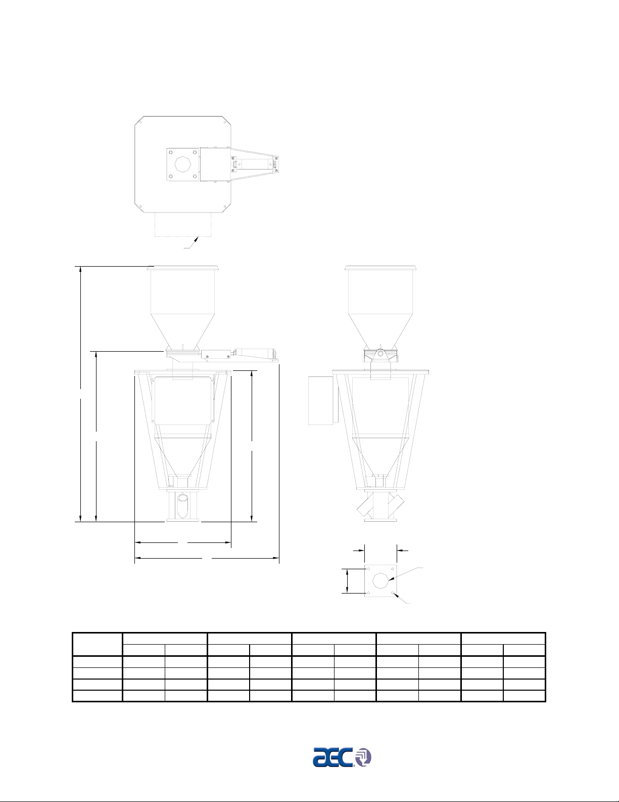
Figure 1
(4)
OFC Series Extrusion Control Unit, Shown with Optional Air-Operated Knife Gate
Panel location
A
D
E
OFC-CHART
B
C
6" sq. BP
8" sq.
ø3.00 discharge (except
OFC-200 ø4.00 discharge)
Drill through 9/16"
four
places
OFC Series Dimensions
ModelABCDE
number inches cm inches cm inches cm inches cm inches cm
OFC-020 60.5 153.7 18 45.7 34 86.4 42 106.7 37.8 95.9
OFC-040 65.5 166.4 18 45.7 33 83.5 42 106.7 37.8 95.9
OFC-100 74.5 189.2 24 70.0 36 91.4 42 106.7 37.8 95.9
OFC-200 80 203.2 30 76.2 45 114.3 47.5 120.7 52.5 133.4
Page 10 OFC Series Extrusion Control Units
Page 11

Safety 2
2-1 Work Rules
Install, operate, and maintain this equipment according to
applicable work and safety codes for your location. This includes
OSHA, CE, NEC, CSA, SPI, and many other local, national, and
international regulations. Obey these specific work rules:
Read and follow the instructions in this manual before
installing, operating, or maintaining any equipment.
Additional copies are available from AEC, Inc.
Only qualified persons should work on, or with, this
equipment.
Work only with approved tools and devices.
Disconnect and lock out power while working on this
equipment.
2-2 Tools and Equipment Needed
You’ll need the following:
• Hand tools
• Fork lift or overhead lift
• Wire, conduit, and fittings for wiring runs (if receptacle is not
already in place)
• Mounting bolts with nuts and washers
2-3 Mechanical Installation
Blenders may be mounted on the machine, a stand, or a mezzanine.
Be sure it is securely attached and additional bracing is used if
necessary. The sections on the following pages explain general
installation rules.
Read manual thoroughly before installing
blender.
Use approved safety straps or chains to lift the
blender at the marked lifting points.
OFC Series Extrusion Control Units Page 11
Page 12
2-4 Safety Considerations
The terms NOTICE, CAUTION, WARNING, and DANGER
have specific meanings in this manual. See Section 9 for a
complete list of specific safety warning information.
A NOTICE is used to indicate a statement of company policy
directly or indirectly related to the safety of personnel or protection
of property.
A CAUTION indicates a potentially hazardous situation which, if
not avoided, may result in minor or moderate injury.
A WARNING indicates a potentially hazardous situation which, if
not avoided could result in death or serious injury.
A DANGER indicates an imminently hazardous situation which, if
not avoided, will result in death or serious injury. This word will
be limited to the most serious situation(s).
The term IMPORTANT emphasizes areas where equipment
damage could result, or provides additional information to make a
step or procedure easier to understand. Disregarding information
marked IMPORTANT would not be likely to cause personal
injury.
REPORTING A SAFETY DEFECT
NOTE: If you believe that your equipment has a defect which could cause
injury, you should immediately discontinue its use and inform
AEC, Inc., at our address listed in this manual.
The principle factors which can result in injury are:
1. Failure to follow proper operating and clean-out procedures,
i.e. lockout/tagout.
2. Failure to maintain a clean and safe working environment.
Page 12 OFC Series Extrusion Control Units
Page 13

2-5 General Responsibility
NO MATTER WHO YOU ARE…
Safety is important. Owners, operators, and maintenance
personnel must realize that every day, safety is a vital aspect of
their jobs.
If your main concern is loss of productivity, remember this:
Production is always affected in a negative way following an
accident. The following are some of the reasons, which can affect
your production:
• Loss of a skilled operator (temporarily or
permanently)
• Breakdown of shop morale
• Costly damage to equipment
• Down-time
An effective safety program is responsible and economically
sound.
Organize a safety committee or group, and hold regular meetings.
Promote this group from the management level. Through this
group, the safety program can be continually reviewed,
maintained, and improved. Keep minutes or a record of the
meetings.
Hold daily equipment inspections in addition to regular
maintenance checks. You will keep your equipment safe for
production and exhibit your commitment to safety.
Please read and use this manual as a guide to equipment safety.
This manual contains safety warnings throughout, specific to each
function and point of operation.
2-6 Operator Responsibility
The operator’s responsibility does not end with efficient
production. The operator usually has the most daily contact with
the blender and intimately knows its capabilities and limitations.
Plant and personnel safety is sometimes forgotten in the desire to
meet incentive rates, or through a casual attitude toward machinery
formed over a period of months or years. Your employer probably
has established a set of safety rules in your workplace. Those
OFC Series Extrusion Control Units Page 13
Page 14

REMEMBER:
rules, this manual, or any other safety information will not keep
you from being injured while operating your equipment.
ONLY YOU can make safety work for you by constantly thinking
about what is safe and what is not. It is often the “just once” that
an operator reaches into a blender to remove material and it results
in serious injury.
Learn and always use safe operation. Cooperate with co-workers
to promote safe practices. Immediately report any potentially
dangerous situation to your supervisor or appropriate person.
• NEVER place your hands or any part of your body in any
dangerous location.
• NEVER operate, service, or adjust the blender without
appropriate training and first reading and understanding this
manual.
• NEVER try to pull material out of the blender with your hands
while it is running!
• Before you start the blender check the following:
• Remove all tools from the blender;
• Be sure no objects (tools, nuts, bolts, clamps, bars) are
laying in the hopper area;
• If your blender has been inoperative or unattended, check all
settings before starting the unit.
• At the beginning of your shift and after breaks, verify that the
controls and other auxiliary equipment are functioning properly.
• Keep all safety guards in place and in good repair. NEVER
attempt to bypass, modify, or remove safety guards. Such
alteration is not only unsafe, but will void the warranty on your
equipment.
• When changing control settings to perform a different mode of
operation, be sure selector switches are correctly positioned.
Locking selector switches should only be adjusted by authorized
personnel and the keys removed after setting.
• Report the following occurrences IMMEDIATELY:
• unsafe operation or condition
• unusual blender action
• leakage
• improper maintenance
Page 14 OFC Series Extrusion Control Units
Page 15

• NEVER stand or sit where you could slip or stumble
into the blender while working on it.
• DO NOT wear loose clothing or jewelry, which can be caught
while working on a blender. In addition, cover or tie back long
hair.
• Clean the blender and surrounding area DAILY, and inspect the
machine for loose, missing or broken parts.
• Shut off power to the blender when it is not in use. Turn the
switch to the OFF position, or unplug it from the power source.
2-7 Maintenance Responsibility
Safety is essential to the good health of both operator and machine.
If you are a maintenance worker, you must make safety a priority
in order to effectively repair and maintain equipment.
BEFORE REMOVING, ADJUSTING, OR REPLACING
PARTS ON A MACHINE, REMEMBER TO DO THE
FOLLOWING:
• TURN OFF all air and electric supplies and all accessory
equipment at the machine.
• DISCONNECT AND LOCK OUT electrical and pneumatic
power, and attach warning tags to the disconnect switch and air
shutoff valve.
When you need to perform maintenance or repair work on a
blender above floor level, use a solid platform or a hydraulic
elevator. If there is a permanently installed catwalk on your
blender, use it. The work platform should have secure footing and
a place for tools and parts. DO NOT climb on blenders, machines,
or work from ladders.
If you need to repair a large component, use appropriate handling
equipment. Before you use handling equipment (portable “A”
frames, electric boom trucks, fork trucks, overhead cranes) be sure
the load does not exceed the capacity of the handling equipment or
cause it to become unstable.
Carefully test the condition of lifting cables, chains, ropes, slings,
and hooks before using them to lift a load.
Be sure that all non-current carrying parts of electrical apparatus,
electrical component enclosures, and the blender frame are
correctly connected to earth ground with an electrical conductor
OFC Series Extrusion Control Units Page 15
Page 16

2-8 Safety
2-8-1 Description and Objectives
that complies with current codes. Install in accordance with
national and local codes, which apply.
When you have completed the repair or maintenance procedure,
check your work, remove your tools, rigging, and handling
equipment.
Do not restore power to the blender until all persons are clear of
the area. DO NOT start and run the blender until you are sure all
parts are functioning correctly.
BEFORE you turn the blender over to the operator for production,
verify all blender enclosure panels, guards and safety devices are
in place and functioning properly.
This section includes information on safety devices and procedures
that are inherent to the OFC Blender. This manual is not intended
to supersede or alter safety standards established by the user of this
equipment. Instead, the material contained in this section is
recommended to supplement these procedures in order to provide a
safer working environment.
At the completion of this section, the operator and maintenance
personnel will be able to:
• Identify and locate specific safety devices.
• Understand the proper use of the safety devices provided.
• Describe the function of the safety devices.
2-8-2 Safety Circuit Standards
Safety circuits used in industrial systems protect the operator and
maintenance personnel from dangerous energy. They also provide
a means of locking out or isolating the energy for servicing
equipment.
Various agencies have contributed to the establishment of safety
standards that apply to the design and the manufacture of
automated equipment. The Occupational Safety and Health
Administration (OSHA) and the Joint Industrial Council (JIC) are
just a few of the organizations that have joined with the plastics
industry to develop safety standards.
Page 16 OFC Series Extrusion Control Units
Page 17

Every effort has been made to incorporate these standards into the
design of the OFC blender; however, it is the responsibility of the
personnel operating and maintaining the equipment to familiarize
themselves with the safety procedures and the proper use of any
safety devices.
2-8-3 Fail Safe Operation
If a safety device or circuit should fail, the design must be such
that the failure causes a “Safe” condition. As an example, a safety
switch must be a normally open switch. The switch must be held
closed with the device it is to protect. If the switch fails, it will go
to the open condition, tripping out the safety circuit.
At no time should the safety device fail and allow the operation
to continue. For example, if a safety switch is guarding a motor,
and the safety switch fails, the motor should not be able to run.
2-8-4 Safety Device Lock-Outs
Some safety devices disconnect electrical energy from a circuit.
The safety devices that are utilized on OFC models are primarily
concerned with the pneumatics and electrical power disconnection,
and the disabling of moving parts that may need to be accessed
during the normal operation of the machine.
Some of the safety devices utilize a manual activator. This is the
method of initiating the safety lock out. This may be in the form of
a plug, disconnect plug, lever or a handle. Within this lockable
handle, there may be a location for a padlock. Personnel servicing
the equipment should place a padlock in the lockout handle.
WARNING! Always disconnect and lockout all electrical power and pneumatic
(i.e. compressed air) sources prior to servicing or cleaning any
Blender, including all OFC units. Failure to do so may result in
serious injury.
At no time must anyone remove the lockout or reconnect the twist
plug, other than the person who installed the lockout or who
unplugged the twist plug.
2-8-5 Lock-Outs, Plugs, and Other Safety Devices
The OFC Blender utilizes several types of safety devices.
The Line Cord Plug
OFC Series Extrusion Control Units Page 17
Page 18

WARNING!
This line cord plug allows the operator or maintenance personnel
to unplug the blender from its power source and tag it out. This
plug may be tagged with any number of approved electrical
lockout tags. These tags are available at most electrical supply
stores.
Disconnect both of these items to ensure optimum maintenance personnel safety
when cleaning or servicing this equipment.
-Notes-
Page 18 OFC Series Extrusion Control Units
Page 19

3 Shipping Information
3-1 Unpacking and Inspection
You should inspect your AEC OFC Series extrusion control unit for possible shipping
damage. If the container and packing materials are in re-usable condition, save them for
re-shipment if necessary.
Thoroughly check the equipment for any damage that might have occurred in transit,
such as broken or loose wiring and components, loose hardware and mounting screws,
etc. In case of breakage, damage, shortage, or incorrect shipment, refer to the following
sections.
3-2 In the Event of Shipping Damages
Important!
According to the contract terms and conditions of the Carrier,
the responsibility of the Shipper ends at the time and place of
shipment.
The Carrier then assumes full responsibility of the shipment.
; Notify the transportation company’s local agent if you discover damage.
; Hold the damaged goods and packing material for the examining agent’s
inspection. Do not return any goods to AEC before the transportation
company inspection and authorization.
; File a claim against the Transportation Company. Substantiate the claim by
referring to the agent’s report. A certified copy of our invoice is available upon
request. The original Bill of Lading is attached to our original invoice. If the
shipment was prepaid, write us for a receipted transportation bill.
; Advise AEC regarding replacement and to obtain a RMA (return material
authorization) or RA (return authorization) number. This number must be
shown and be visible on the outside container for reference upon receipt.
Parcel Post Shipment
; Notify AEC at once in writing, giving details of the loss or damage. This
information is required for filing a claim with our insurance company.
; Hold the damaged goods with the container and packing materials for possible
inspection by postal authorities.
OFC Series Extrusion Control Units Page 19
Page 20

United Parcel Service
; Contact your local UPS office regarding damage and insurance claims.
; Retain the container and packing.
; Notify AEC at once.
3-3 If the Shipment is Not Complete
Check the packing list. The apparent shortage may be intentional. Back-ordered items
are noted on the packing list. You should have:
; AEC OFC Series extrusion control unit
; Bill of lading
; Packing list
; Operating and Installation packet
; Electrical schematic and panel layout drawings
; Component instruction manuals
Re-inspect the container and packing material to see if you missed any smaller items
during unpacking. Determine that the item was not inadvertently taken from the area
before you checked in the shipment. Notify AEC immediately of the shortage.
3-4 If the Shipment is Not Correct
If the shipment is not what you ordered, contact AEC immediately. Include the order
number and item. Hold the items until you receive shipping instructions.
3-5 Returns
Important!
Do not return any damaged or incorrect items
until you receive shipping instructions from AEC.
Page 20 OFC Series Extrusion Control Units
Page 21

4 Operation
4-1 Setup
General Setup and Installation
; Install the OFC unit on the machine throat. Ensure that the unit is mounted
horizontally and is level. Check the installation to ensure that the hopper can
easily be emptied, and that the material supply hopper drop tube is not touching
the weighed colorant hopper. Support or isolate the upper material supply hopper
or blending unit so that it, or the vacuum loading equipment, is not shaking the
weigh hopper so it will not effect the accuracy of the unit.
; Connect the 110 V power to the panel. Ensure that the circuit powering the
control is clean, and does not power other equipment that draws high current
loads that will cause the voltage to fluctuate. Excessive voltage fluctuation can
cause the control to drop out. If this is not possible, install a UPS (uninterrupted
power supply) or Sola Isolation transformer.
; Install the Haul off speed sensing proximity switch on the upper nip roll drive
shaft, provided extruder or haul-off weight per length control or dual control is
selected. This should be done, if possible at the reducer, reading the keyway of
the drive shaft.
; Install the extruder speed sensing proximity switch on the extruder drive motor
shaft, reading the motor shaft keyway, if possible. The proximity switch can be
mounted on the extruder screw; however, it will be less accurate due to less
resolution/revolution.
; Install and wire the remote 5K, 10K or 20K motorized pot to the control panel
terminals, and to the appropriate haul off or extruder speed motor control. An
optional 4-20 ma or 0 to 10 VDC speed control interface is available in lieu of
the motorized pot, if necessary. Consult the factory for additional details.
; Install the appropriate vacuum loading equipment on the virgin supply hopper.
This can be provided at additional charge by AEC or an existing system can be
used. If the OFC unit is to be gravity loaded from an existing upper supply bin or
blender, simply connect a flex hose from the upper discharge to the stub on the
upper loading valve (if ordered with this configuration).
OFC Series Extrusion Control Units Page 21
Page 22

4-2 Unit Calibration and Setup
Scale Calibration
Starting from the #1 Startup menu, press 3, 1, 4, 1. This will bring you directly to the
Scale Calibration menu.
Simply follow the menu prompts to set the hopper empty weight (zero weight), and
then place the calibration weight on the hopper and key in the calibration weight to set
the scale span.
If you want to check the scale periodically, enter the Diagnostics menu (pressing 3, 2, 4
from the #1 Startup menu) to check the scale readout.
If sufficient material is not present in the weigh hopper, the display will notify you of a
load problem.
System Setup
The system setup menu allows adjustment of the software program to conform to the
particular configuration of each system as the application requires.
; Set in the weigh hopper size. This is normally preset in the factory, based on
32#/cu. ft. material, but should be checked. Hopper sizes are approximate and
can vary according to the application. Use the following as a guideline:
Hopper Setting
9” weigh hopper Set in 8#
12” weigh hopper Set in 15#
14” weigh hopper Set in 25#
20” weigh hopper Set in 50#
Note: Some adjustment for bulk density may be required.
If an OFC unit is connected to a host computer system, the unit ID number and
communications baud rate may have to be adjusted before the unit will communicate.
This is done in the communications menu. Set up the host unit first to determine the
proper ID number for each slave unit and then set in the ID number on the slave.
Make sure that all units on the same network are running on the same baud rate (they
will all have to be talking the same communication protocol).
; Program in the haul off roll diameter ft./revolution. This will vary from extruder
to extruder, depending on the size of the roll. This figure will be the actual
circumference of the roll.
; Set in the desired Rate Deviation window by pressing keys
weight per length control or 3, 1, 1, 7 for dual control from the Startup menu.
3, 1, 1, 4 for haul-off
Page 22 OFC Series Extrusion Control Units
Page 23

This function will reset the unit to Monitor mode from Control mode in case the
extruder makes some sudden speed changes, such as being shut down by the
operator when a string up is lost, etc.
; Now you are ready to set in the Recipe for the product you will be running.
Starting from the Startup menu, press 2, 1. A screen will prompt you to enter the
weight/length. Enter the weight/length specification you want, then press
ENTER.
; The menu then instructs you to enter the Stretch Factor, which compensates for
slip on the nip roll, etc. Factory default is 1.00. Adjust up or down after the line
is started, until the actual weighed product weight and the displayed weight
match.
; Start the extruder and start the OFC unit. When you press 1 to start the unit, the
computer automatically sets the pre-programmed Weight/Length and the
Stretch Factor. The OFC unit will always start up in Monitor mode and will not
start adjusting the pot or haul off speed until START is pressed.
Extruder or Haul Off Control
The OFC unit can be configured to operate to adjust either the haul off or the extruder
speed, or both.
Field wire in the motorized pot to the appropriate speed control that you wish to
control. If the unit is displaying the wrong mode, contact the factory to be given the
reconfiguration software code for that particular unit to change it. It will require the
serial number of the unit to be given the proper code.
Display Changes
The second line of the display can show the following:
• Pounds/hour
• Inventory
• Weigh hopper weight
• Extruder or Haul Off Pick-up data
Toggle the ENTER key when the unit is running to display the selected status.
OFC Series Extrusion Control Units Page 23
Page 24

4-3 Menu Structure
Starting from the #1 Startup menu, simply key in the number shown for each item. To
get back to the Startup menu from any display, press the BACKUP key.
STARTUP
> Press 'Start'
MAIN MENU
1) Startup
2) Recipe
3) Setup and
Diagnostics
4) Printer (optional)
RECIPE
SETUP and
DIAGNOSTICS
1) Setup
2) Diagnostics
PRINTER (optional)
1) Test Printer
2) Set Print Interval
3) Set Job Number
4) Print Data
EXTR/HAUL-OFF
WEIGHT/LENGTH
1) Weight per Length
Setting
2) Stretch Factor
EXTRUDER SPEED
CONTROL
1) User Flow Rate
DUAL CONTROL
1) Weight per Length
Setting
2) Stretch Factor
3) User Flow Rate
SETUP
DIAGNOSTICS
1) Extruder Haul-off
2) Data Transmission
3) Communications
4) Scale Readouts
5) Alarm Log
MOTPOT CONTROL
1) Yield Control
2) System Setup
3) Factory Setup
4) Feeder Setup
RATE MONITOR
1) System Setup
2) Factory Setup
3) Feeder Setup
YIELD CONTROL
SYSTEM SETUP
1) Communications
2) Set Time/Date
FACTORY SETUP
1) English/Metric
2) Set User Password
3) EC Options
FEEDER SETUP
1) Scale Calibration
2) Set Hopper Size
3) Set Alarm
Functions
4) Set Start Up Mode
COMMUNICATIONS
SETUP
1) Set Baud Rate
2) Set ID
HAUL-OFF W/L
1) Motpot RPM
2) Control Window
3) Max. Control RPM
4) Rate Deviation
5) Length per Pulse
6) W/L Format
EXTRUDER W/L
1) Motpot RPM
2) Control WIndow
3) Max. Control RPM
4) Length per Pulse
5) W/L Format
EXTRUDER SPEED
CONTROL
1) Motpot RPM
2) Control Window
3) Max. Control RPM
DUAL CONTROL
1) Haul Motpot RPM
2) Extr. Motpot RPM
3) W/L Control
Window
4) Rate Control
Window
5) Haul Control RPM
6) Extr. Control RPM
7) Rate Deviation
8) Length per Pulse
9) W/L Format
Main Menu
1. Startup
2. Recipe
3. Setup & Diagnostics
4. Printer (optional)
1. Startup
2. Recipe
Extruder Haul-Off Weight/Length Control
2.1. Weight/Length Setting
2.2. Stretch Factor
Extruder Speed Control
2.1. User Flow Rate
Dual Control
2.1. Weight/Length Setting
2.2. Stretch Factor
2.3. User Flow Rate
Page 24 OFC Series Extrusion Control Units
Page 25

3. Setup & Diagnostics
3.1. Setup
Motorized Pot Control
3.1.1. Yield Control
Haul-off Weight/Length Control (Motorized Pot Control)
3.1.1.1. Motorized Pot RPM
3.1.1.2. Control Window
3.1.1.3. Maximum Control RPM
3.1.1.4. Rate Deviation
3.1.1.5. Length/Pulse
3.1.1.6. Weight/Length Format
Extruder Weight/Length Control (Motorized Pot Control)
3.1.1.1. Motorized Pot RPM
3.1.1.2. Control Window
3.1.1.3. Maximum Control RPM
3.1.1.4. Length/Pulse
3.1.1.5. Weight/Length Format
Extruder Speed Control (Motorized Pot Control)
3.1.1.1. Motorized Pot RPM
3.1.1.2. Control Window
3.1.1.3. Maximum Control RPM
Dual Control (Motorized Pot Control)
3.1.1.1. Haul-off Motorized Pot RPM
3.1.1.2. Extruder Motorized Pot RPM
3.1.1.3. Weight/Length Control Window
3.1.1.4. Rate Control Window
3.1.1.5. Haul-off Control RPM
3.1.1.6. Extruder Control RPM
3.1.1.7. Rate Deviation
3.1.1.8. Length/Pulse
3.1.1.9. Weight/Length Format
3.1.2. System Setup
3.1.2.1. Communications
3.1.2.1.1. Set Baud Rate
3.1.2.1.2. Set ID
3.1.2.2. Set Time & Date
3.1.3. Factory Setup
3.1.3.1. English or Metric Units
3.1.3.2. Set User Password
3.1.3.3. EC Options
3.1.4. Feeder Setup
3.1.4.1. Scale Calibration
3.1.4.2. Set Hopper Size
3.1.4.3. Set Alarm Actions
3.1.4.4. Set Startup Mode
OFC Series Extrusion Control Units Page 25
Page 26

Rate Monitor
3.1.1. System Setup
3.1.1.1. Communications
3.1.1.2. Set Time & Date
3.1.2. Factory Setup
3.1.2.1. English or Metric Units
3.1.2.2. Set User Password
3.1.2.3. EC Options
3.1.3. Feeder Setup
3.1.3.1. Scale Calibration
3.1.3.2. Set Hopper Size
3.1.3.3. Set Alarm Actions
3.1.3.4. Set Startup Mode
3.2. Diagnostics
3.2.1. Extruder/Haul-off
3.2.2. Data Transmission
3.2.3. Communications
3.2.4. Scale Readouts
3.2.5. Alarm Log
4. Printer
4.1. Test Print
4.2. Set Print Interval
4.3. Set Job Number
4.4. Print Data
3.1.1.1.1. Set Baud Rate
3.1.1.1.2. Set ID
Page 26 OFC Series Extrusion Control Units
Page 27

5 Troubleshooting Tips
Note: Direct any questions you may have concerning our equipment to our office.
5-1 If the Unit Fails to Operate
; Check fuse.
; Check main power.
5-2 If the Unit Stops Intermittently
; Check power line for fluctuations.
; Check the extruder screw speed pick-up proximity switch.
5-3 If the Unit is Inaccurate
; Check weigh hopper for binding or overfill.
; Check proximity sensor mounting and adjustments.
; Check wiring to panel and sensors.
; Check motorized pot for binding (if equipped).
; Check load cell A/D in Diagnostics to ensure that the load cell is not damaged and
is linear. Consult factory.
; Check to see that the additive pellets are feeding consistently out of the weigh
hopper and not bridging occasionally in the hopper discharge throat.
5-4 If Unit Will Not Stay In Control Mode
; Change the Rate Deviation setting to a larger number. The extruder is making
larger speed changes than the window is set for, causing the unit to reset back to
Monitor mode. This is installed in the control software to ensure that the unit does
not control if large speed and rate changes are made quickly.
OFC Series Extrusion Control Units Page 27
Page 28

5-5 Electrical Connections
Refer to the proper AEC electrical drawing(s) depending upon the exact configuration,
as follows:
9 EWB-0531-01 Extruder/haul-off weight per length control (motorized pot)
9 EWB-0531-02 No pot; up/down relays only
9 EWB-0563 Updated version of EWB-0531-01
9 EWB-0563-01 Rate monitor only
9 EWB-0563-02 Haul-off weight per length control
9 EWB-0563-03 Extruder weight per length control
9 EWB-0563-04 Dual control
Figure 2
Sample OFC Electrical Schematics (EWB-0563), Drawing 1
Page 28 OFC Series Extrusion Control Units
Page 29

Figure 2
Sample OFC Electrical Schematics (EWB-0563), Drawing 2
OFC Series Extrusion Control Units Page 29
Page 30

5-6 Replacing the EPROM in the Little Star CPU
Board
Note: Should replacement of the EPROM ever become necessary, follow the
procedures outlined below:
1. With the power off, remove the Eprom (see below). Use an I.C. removal
tool or a small screwdriver to carefully pry each side up until the chip
becomes loose.
Note: There is a notch or indentation on one side of the chip.
2. Install the new Eprom insuring the notch or indented side lines up (as shown
below). Make sure the chip’s legs do not get bent during installation. If the
chip has fewer pins than the socket, make certain that the “flat” end is flush
with the bottom (no notch) of the socket as shown.
Figure 3
Typical EPROM Replacement
Page 30 OFC Series Extrusion Control Units
Page 31

Blender Options 6
The following is a list of options, which your Blender may have been equipped with:
OFC Series Extrusion Control Units Page 31
Page 32

7 Spare Parts List
Check the individual unit for proper sizing before ordering. Please consult with our Parts Dept.
Part no. Part description
A0553614 c Load cell, 10 KG
A0553615 c Load cell, 20 KG
A0553633 c Load cell, 30 KG
A0553634 c Load cell, 50 KG
A0553635 Cylinder, refill valve, conical type
A0553636 Cylinder, slide gate valve
A0553637 Valve, solenoid, refill valve, both types
A0553638 Cone, refill valve
A0553639 Molded slide spacer, slide gate valve
A0553640 c Potentiometer, motorized, 5K
A0553641 c Computer board
A0553642 Display, 2 line X 1/4 inch LCD
A0553643 Power supply, 9V
A0553644 Output module, AC (soldering required to replace)
A0553645 Input module, AC (soldering required to replace)
A0553646 Relay, pot adjust direction
c Indicates recommended spares. Consult factory for pricing.
Important!
Check your unit for proper sizing!
Consult with our Parts Department for current part numbers, pricing
and availability for your particular unit.
- Notes-
Page 32 OFC Series Extrusion Control Units
Page 33

Technical Assistance 8
8-1 Contact Information for Technical Assistance
Parts Department
Call toll-free 7am–5pm CST [800] 423-3183 or call [630] 595-1060
The Parts Department at AEC, Inc. is ready to provide the parts to keep your systems up and running. AEC
replacement parts ensure operation at design specifications. Please have the model and serial number of your
equipment when you call. Consult the Customer Parts List included in your information packet for replacement part
numbers.
Service Department
Call toll-free 8am–5pm CST [800] 233-4819 or call [630] 595-1060
Emergencies after 5pm CST, call [847] 439-5655
AEC has a qualified service department ready to help. Service contracts are available for most AEC products.
Sales Department
Call [630] 595-1060 Monday–Friday, 8am–5pm CST
AEC products are sold by a world-wide network of independent sales representatives. Contact our Sales Department
for the name of the sales representative nearest you.
Contract Department
Call [630] 475-7282 Monday–Friday, 8am–5pm CST
Let AEC install your system. The Contract Department offers any or all of these services: project planning; system
packages including as-built drawings; equipment, labor, and construction materials; union or non-union installations;
and field supervision.
AEC, Inc.
801 AEC Drive
Wood Dale IL 60191-1198
[
630] 595-1060 • Fax [630] 595-6641
OFC Series Extrusion Control Units Page 33
Page 34

8-2 Returned Material Policy
8-2-1 Credit Returns
1. Prior to the return of any material authorization must be given by AEC,
INC. A RMA number will be assigned for the equipment to be returned.
2. Reason for requesting the return must be given.
3. ALL returned material purchased from AEC, INC. returned is subject to
15% ($75.00 minimum) restocking charge.
4. ALL returns are to be shipped prepaid
5. The invoice number and date or purchase order number and date must
be supplied.
6. No credit will be issued for material that is not within the manufacturer’s
warranty period and/or in new and unused condition, suitable for resale.
8-2-2 Warranty Returns
1. Prior to the return of any material, authorization must be given by AEC,
INC. A RMA number will be assigned for the equipment to be returned.
2. Reason for requesting the return must be given.
3. All returns are to be shipped prepaid
4. The invoice number and date or purchase order number and date must
be supplied.
5. After inspecting the material, a replacement or credit will be given, at
AEC’s discretion. If the item is found to be defective in materials or
workmanship, and it was manufactured by AEC, INC., purchased
components are covered under their specific warranty terms.
.
.
Page 34 OFC Series Extrusion Control Units
Page 35

8-3 Warranty
AEC, Inc. warrants all equipment manufactured by it to be free from defects in
workmanship and material when used under recommended conditions. The
Company’s obligation is limited to repair or replace FOB the factory any parts that
are returned prepaid within one year of equipment shipment to the original
purchaser, and which, in the Company’s opinion, are defective. Any replacement
part assumes the unused portion of this warranty.
This parts warranty does not cover any labor charges for replacement of parts,
adjustment repairs, or any other work. This warranty does not apply to any
equipment which, in the Company’s opinion, has been subjected to misuse,
negligence, or operation in excess of recommended limits, including freezing or
which has been repaired or altered without the Company’s express authorization. If
the serial number has been defaced or removed from the component, the warranty
on that component is void. Defective parts become the property of the warrantor
and are to be returned.
The Company is not liable for any incidental, consequential, or special damages or
expenses. The Company’s obligation for parts not furnished as components of its
manufactured equipment is limited to the warranty of the manufacturers of said
parts.
Any sales, use, excise, or other tax incident to the replacement of parts under this
warranty is the responsibility of the purchaser.
The company neither assumes nor authorizes any other persons to assume for it
any liability in connection with the sale of its equipment not expressed in this
warranty.
Many types of AEC, Inc. equipment carry an additional one-year service policy.
Consult your AEC sales representative for specific details.
OFC Series Extrusion Control Units Page 35
Page 36

Safety Tag Information 9
9-1 OFC Blender Safety Tags
Pinch Point Read Operation
Slide Gate and Installation
Manual
Shear Point Earth Ground
Rotating Mixer
High Voltage
Inside Enclosure Ground
Shear Hazard
Rotating Auger
Lifting Point
PE Protected Earth
Page 36 OFC Series Extrusion Control Units
Page 37

9-2 Blender Identification (Serial Number) Tag
(Located on back of Blender)
OFC Series Blender
Model Number OFC-020
Max Blending Capacity HR
460V Serial Number 060701R
1Ǿ Date of Manufacture 06/2003
4.5A
Over-current Protection Device (s) 4.5A Total
Frequency 50/60Hz
Compressed air supply None
Blender Mass 400 lbs/(180 KG)
Electrical Diagrams &
Pneumatic Diagram
801 AEC Drive Wood Dale, Illinois USA
(630) 595-1060
OFC Series Extrusion Control Units Page 37
Page 38

Service Notes
Page 38 OFC Series Extrusion Control Units
Page 39

AEC, Inc. warrants all equipment manufactured by it to be free from defects in workmanship and
material when used under recommended conditions. The Company’s obligation is limited to repair
or replace FOB the factory any parts that are returned prepaid within one year of equipment
shipment to the original purchaser, and which, in the Company’s opinion, are defective. Any
replacement part assumes the unused portion of this warranty.
This parts warranty does not cover any labor charges for replacement of parts, adjustment repairs,
or any other work. This warranty does not apply to any equipment which, in the Company’s opinion,
has been subjected to misuse, negligence, or operation in excess of recommended limits, including
freezing or which has been repaired or altered without the Company’s express authorization. If the
serial number has been defaced or removed from the component, the warranty on that component
is void. Defective parts become the property of the warrantor and are to be returned.
The Company is not liable for any incidental, consequential, or special damages or expenses. The
Company’s obligation for parts not furnished as components of its manufactured equipment is
limited to the warranty of the manufacturers of said parts.
Any sales, use, excise, or other tax incident to the replacement of parts under this warranty is the
responsibility of the purchaser.
The company neither assumes nor authorizes any other persons to assume for it any liability in
connection with the sale of its equipment not expressed in this warranty.
Many types of AEC, Inc. equipment carry an additional one-year service policy. Consult your AEC
sales representative for specific details.
801 AEC Drive • Wood Dale, Illinois 60191-1198 USA
Phone (630) 595-1060 • Fax (630) 595-6641
http://www.aecinternet.com
Page 40

801 AEC Drive • Wood Dale, IL 60191-1198 USA
(630) 595-1060 • Fax (630) 595-6641
http://www.aecinternet.com
 Loading...