

AEC NEC Central Station Air and Water Cooled Chiller User Manual
$30.
00
Operation and Installation Manual
NEC Series
Water- and Air-Cooled
Central Chillers
Important! Read Carefully Before Attempting to Install or Operate Equipment
Part No. A0537138 Bulletin No. AE3-605A

Performance figures stated in this manual are based on a standard atmosphere of 59°F
(15°C) at 29.92” Hg (1,014 millibars) at sea level, using 60 hz power. Altitude is an
important consideration when specifying chillers. AEC/Application Engineering can
advise you on proper selection and sizing of systems for your operating environment.
AEC/Application Engineering is committed
to a continuing program of product improvement.
Specifications, appearance, and dimensions described in this manual
are subject to change without notice.
© Copyright AEC/Application Engineering and AEC, Inc. 2008
All rights reserved. Effective 3/14/2008
Part No. A0537138 Bulletin No. AE3-605A.3
Page 2 NEC Series Water- and Air-Cooled Central Chillers

Please note that our address and phone information has changed.
Please reference this page for updated contact information.
These manuals are obsolete and are provided only for their technical information, data and capacities.
Portions of these manuals detailing procedures or precautions in the operation, inspection, maintenance
and repair of the products may be inadequate, inaccurate, and/or incomplete and shouldn’t be relied
upon. Please contact the ACS Group for more current information about these manuals and their
warnings and precautions.
Parts and Service Department
The ACS Customer Service Group will provide your company with genuine OEM quality parts manufactured to engineering
design specifications, which will maximize your equipment’s performance and efficiency. To assist in expediting your phone
or fax order, please have the model and serial number of your unit when you contact us. A customer replacement parts list
is included in this manual for your convenience. ACS welcomes inquiries on all your parts needs and is dedicated to
providing excellent customer service.
For immediate assistance, please contact:
• North, Central and South America, 8am – 5pm CST +1 (800) 483-3919 for drying, conveying, heating and cooling
and automation. For size reduction: +1 (800) 229-2919.
North America, emergencies after 5pm CST (847) 439-5855
North America email: acsuscanadacustserv@corpemail.com
• Mexico, Central & South America
Email: acslatinamericacustserv@corpemail.com
• Europe, Middle East & Africa +48 22 390 9720
Email: acseuropecustserv@corpemail.com
• India +91 21 35329112
Email: acsindiacustserv@corpemail.com
• Asia/Australia +86 512 8717 1919
Email: acsasiacustserv@corpemail.com
Sales and Contracting Department
Our products are sold by a worldwide network of independent sales representatives. Contact our Sales Department for the
name of the sales representative nearest you.
Let us install your system. The Contract Department offers any or all of these services: project planning; system packages
including drawings; equipment, labor, and construction materials; and union or non-union installations.
For assistance with your sales or system contracting needs please Call:
North, Central and South America +1 (262) 641-8600 or +1 (847) 273-7700 Monday–Friday, 8am–5pm CST
Europe/Middle East/Africa +48 22 390 9720
India +91 21 35329112
Asia/Australia +86 512 8717 1919
Facilities:
ACS offers facilities around the world to service you no matter where you are located. For more information, please visit us at
www.acscorporate.com
United States:
ACS Schaumburg – Corporate Offices
1100 E. Woodfield Road
Suite 588
Schaumburg, IL 60173
Phone: + 1 847 273 7700
Fax: + 1 847 273 7804
ACS New Berlin – Manufacturing Facility
2900 S. 160th Street
New Berlin, WI 53151
Phone : +1 262 641 8600
Fax: + 1 262 641 8653
Asia/Australia:
ACS Suzhou
109 Xingpu Road SIP
Suzhou, China 215126
Phone: + 86 8717 1919
Fax: +86 512 8717 1916
Europe/Middle East/Africa:
ACS Warsaw
Ul. Działkowa 115
02-234 Warszawa
Phone: + 48 22 390 9720
Fax: +48 22 390 9724
India
ACS India
Gat No. 191/1, Sandbhor Complex
Mhalunge, Chakan, Tal Khed,
Dist. Pune 410501, India
Phone: +91 21 35329112
Fax: + 91 20 40147576

Safety Considerations
AEC/Application Engineering NEC Series central chillers are designed to provide safe and
reliable operation when installed and operated within design specifications, following national
and local safety codes. To avoid possible personnel injury or equipment damage when installing,
operating, or maintaining this equipment, use good judgment and follow these safe practices:
; Follow all SAFETY CODES.
; Wear SAFETY GLASSES and WORK GLOVES.
; Use care when LOADING, UNLOADING, RIGGING, or MOVING this equipment.
; Operate this equipment within design specifications.
; OPEN, TAG, and LOCK ALL DISCONNECTS before working on equipment. It’s a good
idea to remove the fuses and carry them with you.
; Make sure the chiller is properly GROUNDED before switching on power.
; When welding or brazing in or around this equipment, be sure VENTILATION is
ADEQUATE. PROTECT adjacent materials from flame or sparks by shielding with sheet
metal. An approved FIRE EXTINGUISHER should be close at hand and ready for use if
needed.
; The refrigeration system can develop refrigerant pressures in excess of 500 psi. DO NOT
CUT into the system without first relieving pressure.
; Do not jump or bypass any electrical safety control.
; Do not restore power until all tools, test equipment, etc. have been removed and the panels
replaced.
; Only PROPERLY TRAINED personnel familiar with the information within this manual
should work on this equipment.
NEC Series Water- and Air-Cooled Central Chillers Page 3

Table of Contents
1 General Information .................................................7
1-1 Introduction
1-2 Necessary Documents
1-3 Models Covered
1-4 Available Options
1-5 Incorrect Shipment
2 Shipping Information................................................9
2-1 Unpacking and Inspection
2-2 In the Event of Shipping Damages
2-3 If the Shipment is Not Complete
2-4 If the Shipment is Not Correct
2-5 Returns
2-6 Uncrating
3 Installation...............................................................13
3-1 Electrical Connections
3-2 Process Water Connections
3-3 Water Connection Sizing
3-4 Galvanic Corrosion
3-5 Water Treatment
3-6 Water-Cooled Condenser Water Connections
3-7 Air-Cooled Condenser Installation
3-8 Motor Direction Check
4 Sequence of Operation .........................................29
4-1 Chilled Water Circuit
4-2 Refrigeration Circuit
4-3 Freezestat Control
4-4 Crankcase Heater
4-5 High Pressure Cutout
Page 4 NEC Series Water- and Air-Cooled Central Chillers

Table of Contents
4 Sequence of Operation ..................................Cont’d.
4-6 Low Pressure Cutout
4-7 Oil Pressure Safety Switch
4-8 Flow Switch
4-9 Remote Start/Stop Interlock
4-10 Control Nipple
4-11 Control Probe
4-12 Hot Gas Bypass (Optional)
4-13 Chilled Water Manifold (Optional)
4-14 Condenser Water Manifold (Optional)
5 Startup Checklists..................................................35
5-1 Introduction
5-2 Water-Cooled NECW Startup Checklist
5-3 Water-Cooled NECW Chiller Startup
5-4 Air-Cooled NECR Startup Checklist
5-5 Air-Cooled NECR Chiller Startup
6 Graphic Panel..........................................................39
6-1 Indicator Lights
6-2 Switches
7 Routine Maintenance .............................................45
7-1 Lubrication
7-2 Condenser Maintenance
7-3 Evaporator Maintenance
7-4 Preventive Maintenance Service
8 Troubleshooting Checklist ....................................55
NEC Series Water- and Air-Cooled Central Chillers Page 5

Charts and Figures
1
NECW Water-Cooled Chiller Design Specifications 8
2
NECR Air-Cooled Chiller Design Specifications 9
3
One Circuit Dimensions Components and Clearances 10
4
Two Circuit Dimensions Components and Clearances 11
5
Three Circuit Dimensions Components and Clearances 12
6
Typical Air-Cooled Condenser Packages 13
7
Remote Air-Cooled Condenser Dimensions 14
8
Evaporator GPM Pressure Drop Curves 16
9
10
11
12
13
14
15
16
17
18
Condenser GPM Pressure Drop Curves 17
Typical Remote Air-Cooled Condenser Piping Installation 20
One Circuit One Pump Piping Schematic 21
One Circuit Two Pump Piping Schematic 21
One Circuit No Tank Piping Schematic 22
One Circuit No Pump No Tank Piping Schematic 22
Freezing Protection Curve 24
Typical Graphic Panel 30
Typical Subpanel Layouts 33
Typical NEC Chiller Electrical Schematic 34
Page 6 NEC Series Water- and Air-Cooled Central Chillers

1 General Information
1-1 Introduction
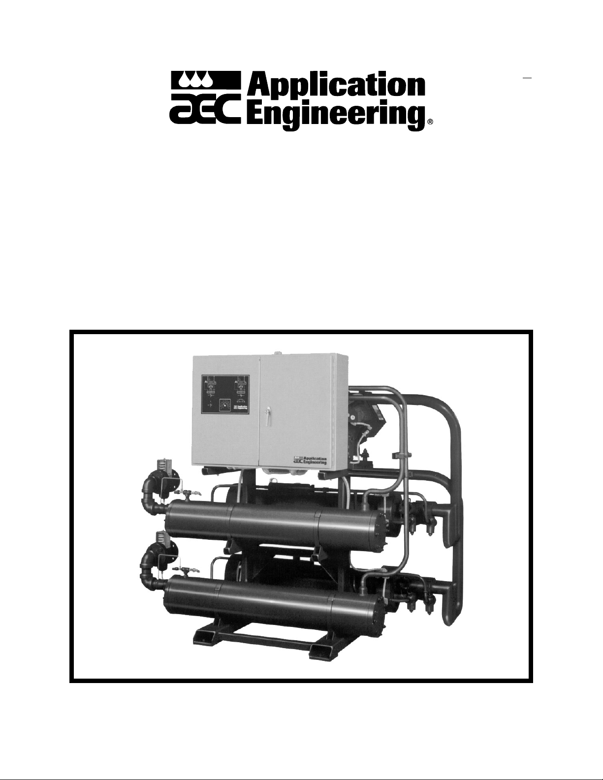
AEC/Application Engineering NEC Series Central Water Chillers are available in water-cooled
(NECW) and remote air-cooled (NECR) designs. They differ only in the condensing media used.
NEC units can be configured with one, two, or three independent circuits using 10 to 60 hp
compressors for each circuit.
This manual describes single-circuit NEC units. References are made to multiple circuit units as
needed.
A properly installed, operated, and maintained NEC chiller will provide many years of reliable
operation. To get the most satisfaction from your new chiller, read and follow the
instructions in this manual.
1-2 Necessary Documents
These documents are necessary for the operation, installation, and maintenance of AEC/
Application Engineering NEC chillers. Additional copies are available from AEC, Inc.
Familiarize the appropriate personnel with the following documents:
• This manual.
• The schematic and connection diagram in the control enclosure.
• Operation and installation manuals for accessories and options selected by the customer.
• The Customer Parts List included in the information packet.
1-3 Models Covered
Model numbers are listed on the chiller serial tag. A Q following the model number indicates a
specially constructed unit; not all information in this manual may apply. Please know the model
number, serial number, and operating voltage of your chiller if you need to contact AEC, Inc.
NEC chiller models are designated by the number of refrigeration circuits, total compressor
horsepower of all circuits (10 through 180), and the cooling method used. Air-cooled models are
designated
cooled NEC with three 10 hp compressors is designated as
NECR and water-cooled models are designated NECW. For example, a 3-circuit air-
NECR-3-30.
NEC Series Water- and Air-Cooled Central Chillers Page 7

NECR-2 and NECR-3 chillers with an A suffix are supplied with alternate remote air-cooled
condenser selections. See Figure 7 – Remote Air-Cooled Condenser Dimensions on Page 14 for
more information.
1-4 Available Options
NEC chillers are available with options to tailor the unit to your requirements. Some are factory
installed and some can be retro-fitted in the field. Consult your sales representative for more
information.
Operating Voltages
NEC chillers are available configured for 208/230-3-60, 380/415-3-50, 460-3-60,
515-3-50, and 575-3-60 volts.
Cooling Ranges
NEC chillers are offered in two cooling ranges. Standard chillers using R-22 refrigerant are used
with 30°F (-1ºC) to 65°F (18ºC) leaving water temperature processes. Low-temperature R-22
units are available for use with leaving water temperatures below 30ºF (-1ºC). Please note that
the temperature scales on the control panel exceed these ranges, but optimum operation is
achieved within the stated ranges.
Special Manifolds
Chilled water and condenser water supply and return manifolds are available in both steel and
plastic pipe.
Hot Gas Bypass
A hot gas bypass system is offered for processes with low cooling loads.
Lead-Lag Control
Lead-lag controls, available on NEC-2 and NEC-3 chillers, allow the operator to distribute
service time between compressors.
Gauge Option
Factory-installed thermometers and pressure gauges on the evaporator inlet(s) and outlet(s)
facilitate flow balancing.
Low Voltage Monitor
An auto-reset low voltage monitor protects the compressor and control circuit from potentially
damaging brownout conditions.
Page 8 NEC Series Water- and Air-Cooled Central Chillers
2 Shipping Information
2-1 Unpacking and Inspection
You should inspect your AEC/Application Engineering NEC Series central chiller for possible
shipping damage. If the container and packing materials are in re-usable condition, save them for
reshipment if necessary.
Thoroughly check the equipment for any damage that might have occurred in transit, such as
broken or loose wiring and components, loose hardware and mounting screws, etc. In case of
breakage, damage, shortage, or incorrect shipment, refer to the following sections.
2-2 In the Event of Shipping Damages
Important!
According to the contract terms and conditions of the Carrier,
the responsibility of the Shipper ends at the time and place of shipment.
The Carrier then assumes full responsibility of the shipment.
; Notify the transportation company’s local agent if you discover damage.
; Hold the damaged goods and packing material for the examining agent’s inspection. Do not
return any goods to AEC, Inc. before the transportation company inspection and
authorization.
; File a claim against the transportation company. Substantiate the claim by referring to the
agent’s report. A certified copy of our invoice is available upon request. The original Bill of
Lading is attached to our original invoice. If the shipment was prepaid, write us for a
receipted transportation bill.
; Advise AEC, Inc. regarding your wish for replacement and to obtain an RMA (return
material authorization) number.
NEC Series Water- and Air-Cooled Central Chillers Page 9

2-3 If the Shipment is Not Complete
Check the packing list. The apparent shortage may be intentional. Back-ordered items are noted
on the packing list.
You should have:
; AEC/Application Engineering NEC Series central chiller
; Bill of lading
; Packing list
; Operating and Installation packet
; Electrical schematic and panel layout drawings
; Component instruction manuals
Re-inspect the container and packing material to see if you missed any smaller items during
unpacking. Determine that the item was not inadvertently taken from the area before you
checked in the shipment. Notify AEC, Inc. immediately of the shortage.
2-4 If the Shipment is Not Correct
If the shipment is not what you ordered, contact AEC, Inc. immediately. Include the order
number and item. Hold the items until you receive shipping instructions.
2-5 Returns
Important!
Do not return any damaged or incorrect items
until you receive shipping instructions from AEC, Inc.
Page 10 NEC Series Water- and Air-Cooled Central Chillers

2-6 Uncrating
Note: Due to the size and weight of NEC chillers, AEC, Inc. recommends using bonded
professional millwrights to unload and move NEC chillers.
Rig the chiller from the frame only, using spreader bars to prevent load transfer to any chiller
components. Rig the frame from at least four points and balance the load before lifting to clear
the skid. Lift the chiller slowly and only high enough to clear the skid. Use a pry bar to free the
skid if necessary. Lower slowly.
Use a forklift of adequate size when lifting the chiller by the fork pockets. Enter the fork pockets
from the control enclosure side. Insert the forks all the way into the pockets and be sure to
balance the load before lifting the chiller to clear the skid. Lift only as high as necessary. Use a
pry bar to free the skid if necessary. Lower slowly.
Retain the crating in case reshipment is necessary due to hidden shipping damage.
Caution!
Due to the weight of these units,
use extreme caution
when moving and placing NEC chillers.
NEC Series Water- and Air-Cooled Central Chillers Page 11

- Notes -
Page 12 NEC Series Water- and Air-Cooled Central Chillers
3 Installation
3-1 Electrical Connections
Figures 1 and 2
Check the serial tag voltage and amperage requirements and make sure your electrical service
conforms.
Bring properly sized power leads and ground from a fused disconnect (installed by your
electrician) to the unit. Use fuses in the disconnect switch, sized according to the National
Electrical Code recommendations listed on the electrical schematic in the control enclosure.
! WARNING !
• Electrical connections must comply with all applicable electrical
codes.
• The chiller must be grounded in accordance with NEC Article 250.
• Voltage must be within plus or minus ten percent (±10%) of the
nameplate rating.
• Phase imbalance must be less than 2% in accordance with NEMA
MG1-14.32.
• Air-cooled remote condensers must have properly-sized
disconnects conforming with all local codes.
NEC Series Water- and Air-Cooled Central Chillers Page 13
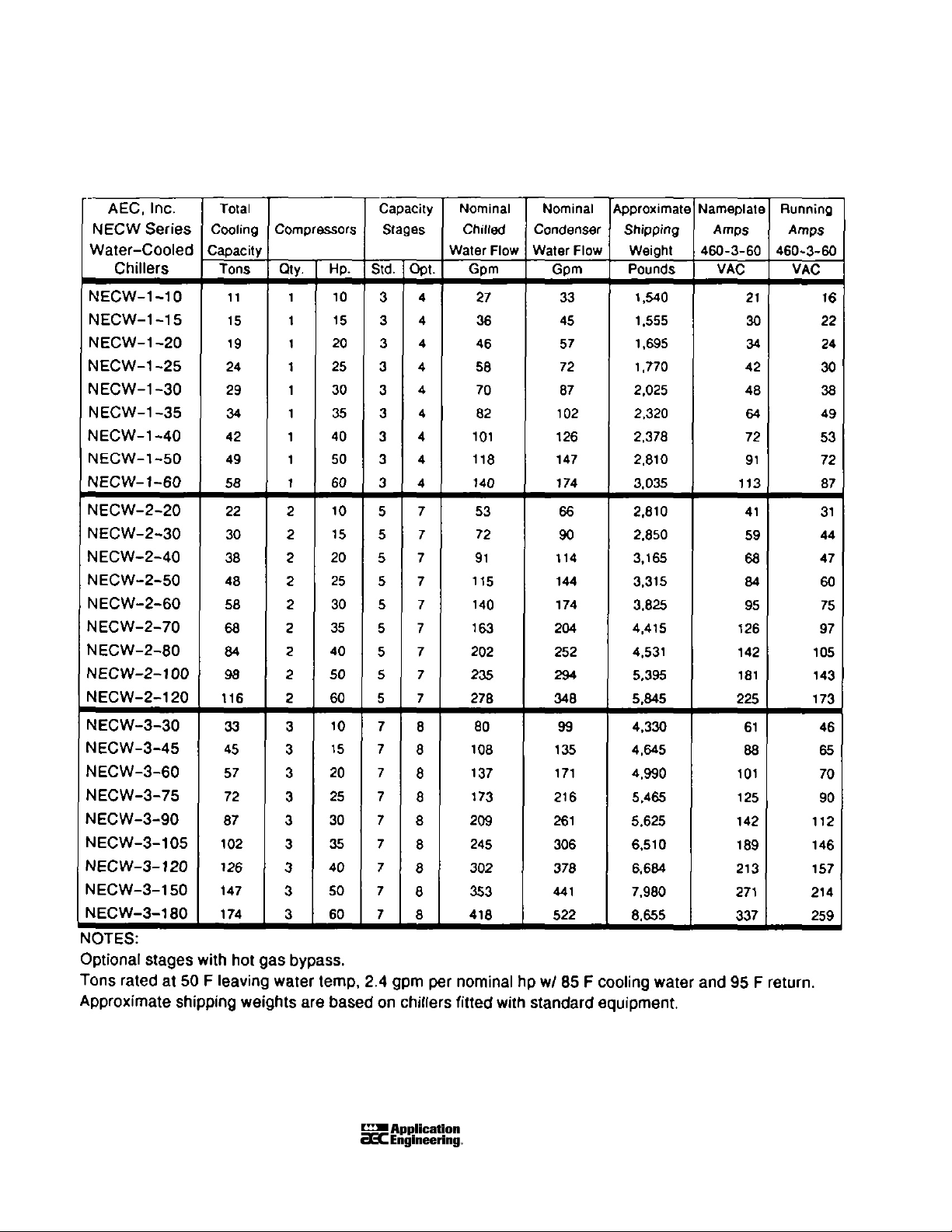
Figure 1
NECW Chiller Design Specifications
Page 14 NEC Series Water- and Air-Cooled Central Chillers
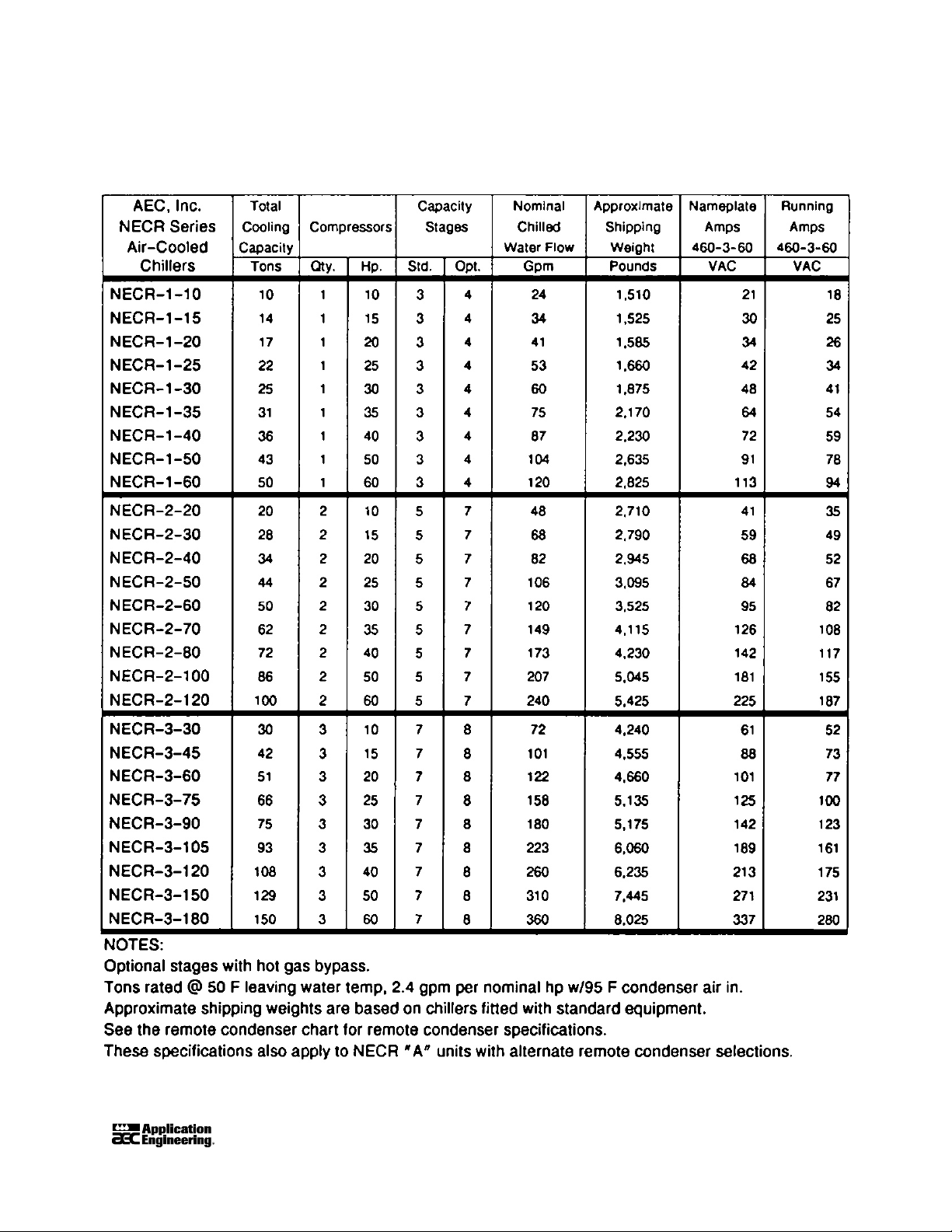
Figure 2
NECR Chiller Design Specifications
NEC Series Water- and Air-Cooled Central Chillers Page 15
 Loading...