

AEC Matador 0853 Driver's Manual

BOOK
No.
IOO
j F.W.2A.
DRIVER'S
TRACTOR,
A.
E.
C.
Model
(Air
Pressure
THE ASSOCIATED EQUIPMENT CO. LTD.
HANDBOOK
FOR
4 x 4
"M
October,
A T
0853-C.1.
Assisted
MEDIUM
ADO
Engine
Hydraulic
1943.
Brakes).
·
R"

2.
FUEL
,
VENT
TANK
pIPE
Fig. 1. Arrangement
of
Chassis.
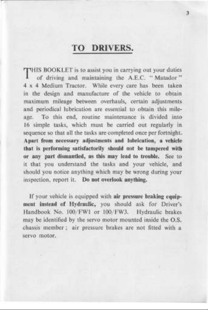
TO DRIVERS.
HIS BOOKLET is to assist you in carrying out your duties
T
of
driving
4 x 4 Medium Tractor. While every care has been taken
in the design
maximum mileage between overhauls, certain ' adjustments
and
periodical lubrication are essential to obtain this mile-
age.
sequence so that all the tasks are completed once per fortnight.
that is performing satisfactorily should not
or
it that you understand the tasks
should you notice anything which may be wrong during your
inspection, report it. Do not overlook anything.
To
16
simple tasks, which must be carried
Apart from necessary adjustments and lubrication, a vehicle
any part dismantled, as this may lead to trouble. See to
and
maintaining the A.E.C.
and
manufacture
this end, routine maintenance is divided
of
the vehic!e to obtain
and
"Matador"
out
regularly
be
tampered with
your vehicle,
into
in
and
3
If
your vehicle
ment instead
Handbook
may be identified by the servo motor mounted inside the
chassis
servo motor.
member;
is
equipped with air pressure braking equip-
of
Hydraulic, you should ask
No.
IOO/FW 1 or
air pressure brakes are
lOO
for
Driver's
j FW3. Hydraulic brakes
not
fitted with a
O.S.
4
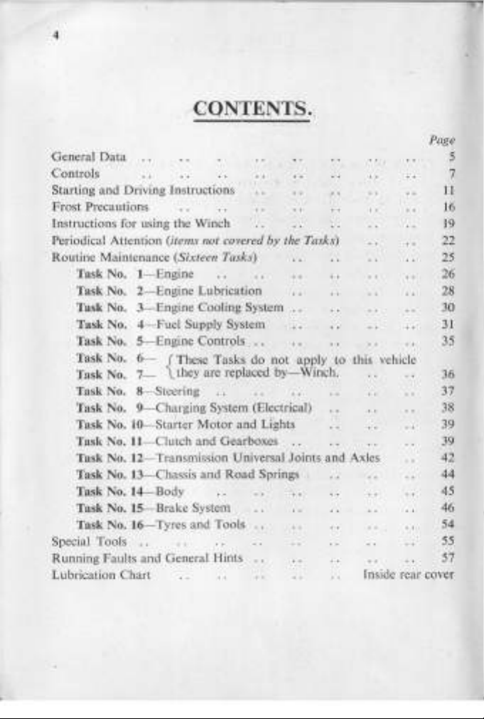
,CONTENTS.,
General
Controls
Starting
Frost
Instructions for using
Periodical Attention (items not covered
Routine Maintenance (Sixteen Tasks)
Special Tools
Running Faults and General Hints
Lubrication Chart
Data
and
Driving Instructions '
Precautions
the
Winch
Task No. 'I- Engine
Task No. 2- Engine Lubrication
Task No. 3- Engine Cooling System
Task No. 4Task
No.
Fuel
Supply System
S~Engine
Contr~ls
,
. . 35
Task No. 6- f These Tasks do
Task No. 7Task
No. 8- Steering
l they are replaced
Task No. 9- Charging System (Electrical)
Task No.
Task No.
Task
Task
10-Sta~ter
ll
- Clutch
Motor
and
Gearboxes
and
No. 12- Transmission Universal Joints
No. 13- Chassis
and
Road
Task No. I4- Body
Task No.
IS-Brake
System
Task No. I6- Tyres and Tools
..
by
the Tasks)
, ,
not
apply to this vehicle
by-Winch.
Lights
and
Springs
Axles
fnside rear cover
Page
5
7
11
16
19
22
25
26'
28
30
31
36
37
38
39
39
42
44
45
46
54
55
57
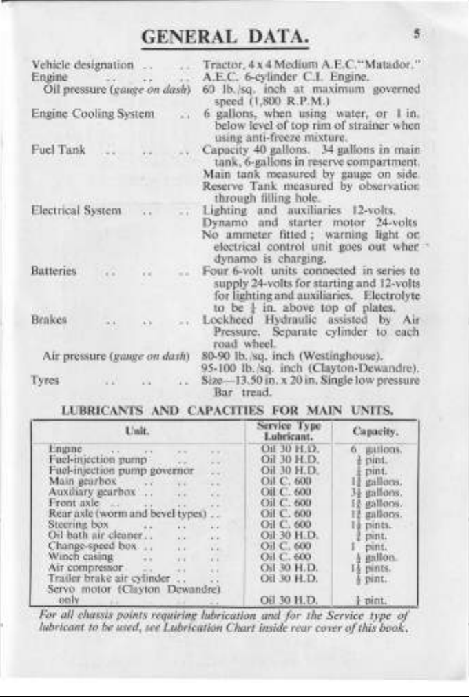
GENERAL DATA.
Vehicle designation
Engine
Oil pressure (gauge on dash)
Engine Cooling System
Tank
Fuel
Electrical System
Batteries
Brakes
Air pressure
Tyres
LUBRICANTS AND CAPACITIES
Engme
Fuel-injection
Fuel-injection pump governor
Main gearbox
Auxiliary gearbox
Front
axle
Rear
axle (worm and bevel types) . . Oil C. 600
Steering box
Oil bath air cleaner
Change-speed box
Winch casing
Air compressor
Trailer brake air cylinder
motor
Servo
only
For
all
chaSSIS
lubricant to be
..
(gauge on dash)
Unit.
. .
pump
.. . .
(Clayton Dewandre)
..
POll1ts
lIsed,
· .
· . · .
· .
· . · . · .
..
· . · .
..
· .
· . · .
· . · .
· .
· .
· . · .
..
requiring lubrication and for the Service type
see Lubrication Chart inside rear cover
Tractor,
Medium A.E.
C."Matador."
4x4
A.E.C. 6-cylinder C.l. Engine.
60 lb./
sq. inch
(1,800 R.P.M.)
speed
6 gallons, when using water,
below level
at
maximum governed
of
top
rim
of
or
I in.
strainer when
using anti-freeze mixture.
Capacity
40 gallons. 34 gallons in main
tank, 6-gallons in reserve compartment.
tank
Main
Reserve
measured by gauge
Tank
measured
by
observation
on
side.
through filling hole.
and
Lighting
Dynamo
No
ammeter
electrical control unit goes
auxiliaries 12-volts.
and
starter
fitted;
warning light
motor
24-volts
out
wher -
o(
dynamo is charging.
Four
6-volt units connected in series
supply 24-volts for starting
and
for lighting
t in. above
to be
auxiliaries. Electrolyte
top
and
of
Lockheed Hydraulic assisted
plates.
to
12-volts
by
Air
Pressure. Separate cylinder to each
road
wheel.
80-90 lb./sq. inch (Westinghouse).
95-100 lb. /sq. inch (Clayton-Dewandre).
Size- 13.50 in. x
20 in. Single low pressure
Bar tread.
FOR
..
· .
· .
..
· .
· .
..
· .
Service Type
--
MAIN
Lubricant.
Oil
30
H.D.
OiI30H
Oil 30 H.D.
Oil C. 600
Oil C. 600
Oil C. 600
Oil C. 600
Oil
Oil C. 600
Oil C. 600
Oil
Oil
OiI30H.D.
30
30
30
.D.
H.D.
H.D.
H.D.
UNITS.
Capacity.
gallons .
6
!
pint.
t pint.
If
gallons.
3!
gallons.
It
gallons.
It
gallons.
I!
pints.
t pint.
pint.
I
!
gallon.
J! pints .
! pint.
1 pint.
of
of
this book.
5
NUMBERS.
INDEX
Pedal.
Brake Lever.
TO
Brake
Hand
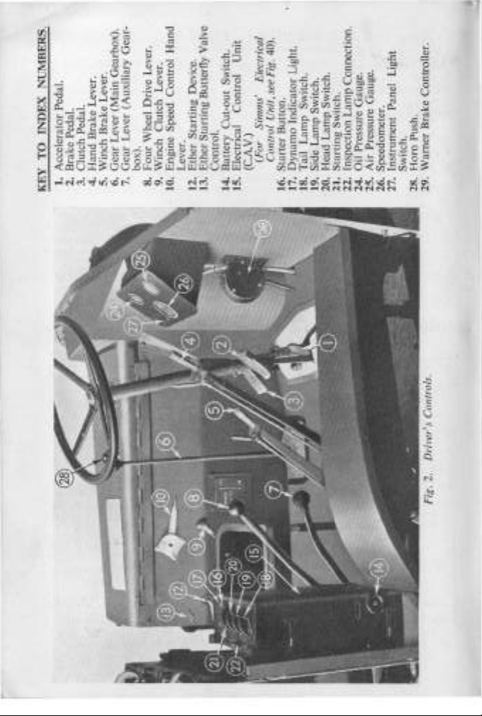
1. Accelerator Pedal.
2.
3. Clutch Pedal.
KEY
4.
Gear-
Gearbox).
Lever.
(Main
Brake
Lever (Auxiliary
Lever
Gear
Gear
5. Winch
7.
6.
Wheel Drive Lever.
box).
Four
8.
Hand
Lever.
9. Winch Clutch Lever.
10. Engine Speed Control
Starting Device.
Starting Butterfly Valve
Ether
Ether
12.
13.
Unit
Switch.
Control
Cut-out
Control.
14. Battery
15. Electrical
.)
Control Unit, see Fig. 40).
(For Simms' Electrical
(C.A.V
Light.
Switch.
Indicator
Lamp
Dynamo
18. Tail
16. Starter Button.
17.
Switch.
Switch.
Lamp
Lamp
Side
19.
20. Head
21. Starting Switch.
Connection.
Lamp
Oil Pressure Gauge.
25. Air Pressure Gauge.
26. Speedometer.
24.
27. Instrument Panel Light
22. Inspection
Brake Controller.
Horn Push.
Warner
Switch.
29.
28.
Fig. 2. Driver's Controls.
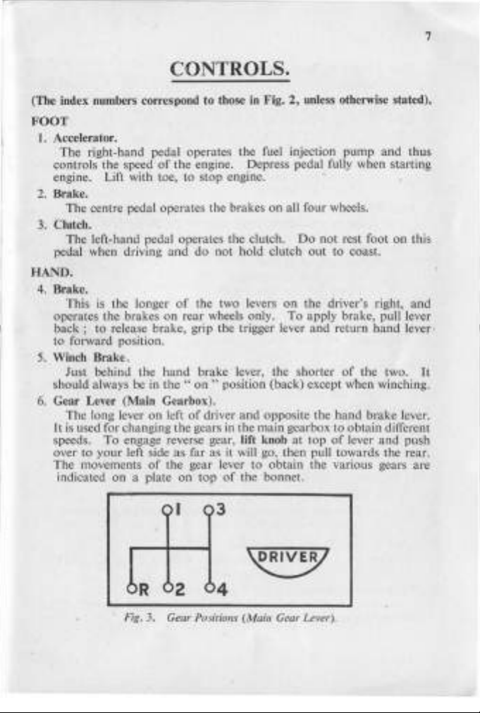
CONTROLS.
(The index numbers correspond to those in Fig. 2, unless otherwise stated).
FOOT
1.
Accelerator.
The
right-hand pedal operates the fuel injection
controls the speed
engine. Lift with toe, to
2. Brake.
The centre pedal operates the brakes
3.
Clutch.
The left-hand pedal operates the clutch.
pedal when driving
HAND.
4.
Brake.
This
is
operates the brakes
back;
to
forward position.
S.
Winch Brake,
Just behind the
should always be in
6.
Gear Lever (Main Gearbox).
The long lever on left
It
is used for changing
speeds.
over to
The movements
indicated
the longer
to release brake, grip the trigger lever
To
your
on
of
the engine. Depress pedal fully when starting
stop
and
do
of
the two levers
on
rear
hand
brake lever, the shorter
the"
on
of
driver
the
engage reverse gear, lift knob
left side
of
a plate
gears in the
as
far as it will go, then pull towards the rear.
the
gear lever
on
top
engine.
on
all four wheels.
not
hold clutch
wheels only.
" position (back) except when winching.
and
to
of
the bonnet.
Do
on
To
opposite the
main
gearbox to obtain different
at
obtain
pump
and
thus
not
rest foot
out
to coast.
the driver's right,
apply brake, pull lever
and
return
of
hand
top
of
lever
the various gears are
on
hand
lever·
the two.
brake lever.
and
push
this
and
It
7
01
(3
02
04
Fig. 3. Gear Positions (Main Gear Lever).
7.
Gear Lever (Auxiliary Gearbox).
The outside ball handle lever
th~
changing
for normal road
drive. Low gear
auxiliary gear to high,
work;
low
cannot
at
right
of
the driver.
or
or
high gear may be used with four wheel
low. High gear is always used
It
is
be engaged unless front wheel drive
used.
of
lever
is
Movement
Up
for low gear.
:-
Central for neutral (position for winching).
Down
for high gear.
8.
Four Wheel Drive Lever.
The
inside ball handle lever
four wheel drive
or
rear wheel drive only.
at
right
of
the driver is for engaging
Rear wheel drive is always used for normal road work.
Movement
9.
Winch Clutch Lever.
This
is
Movement
Except during winching, this lever must be
of
lever is
Up
for four wheel drive.
Down
for rear wheel drive.
on
the driver's left
of
lever is :-
Up
for clutch out.
Down
for clutch in.
:-
at
the rear.
in
the"
up " position
in the clip provided.
10.
Engine Speed Control Hand Lever.
The
small lever mounted on the side
Tt
is
used
driver.
to
regulate the speed
of
the bonnet to the left
of
the engine, as during
winching, without the necessity for keeping foot on the the accelerator
It
pedal.
be stopped,
11.
Winch Engagement Lever (Fig.
Mounted
must be in the shut position (down) before the engine can
by
lifting the accelerator pedal.
1).
on
the auxiliary gearbox
on
the nearside
of
the vehicle.
Move forward to engage winch drive.
12.
Ether Starting Device (when fitted).
This
is
mounted
by a lever
13.
Ether Starting Butterfly Valve Control (when fitted).
The small knob
instructions see page 12).
on
(for
the left side
instructions see page 12).
at
the rear
on
of
the driver's seat
the .driver's side
and
is
of
the bonnet (for
used for
is
also
of
the
operated
14.
Battery Cut-out Switch (C.A.V.)
Knob
presse.d
the battery
the Electrical Control
Control
15.
Electrical Control Unit. (Units
are fitted, the controls
shown
the following
16.
Starter Button.
17.
Dynamo Indicator Light.
and the starting switch (21)
or
the dynamo
18.
Tail Lamp Switch. This also controls the axle flood lamp.
19.
Side Lam p Switch.
20.
Head Lamp Switch.
21. Starting
it must be left in this position while the engine
the vehicle
must be switched
the engine stopped by lifting
the accelerator pedal.
22. Inspection Lamp Connection.
2-pin plug attached to the
inspection lamp supplied.
The battery cut-out switch
,
1-
(14) must
this lamp.
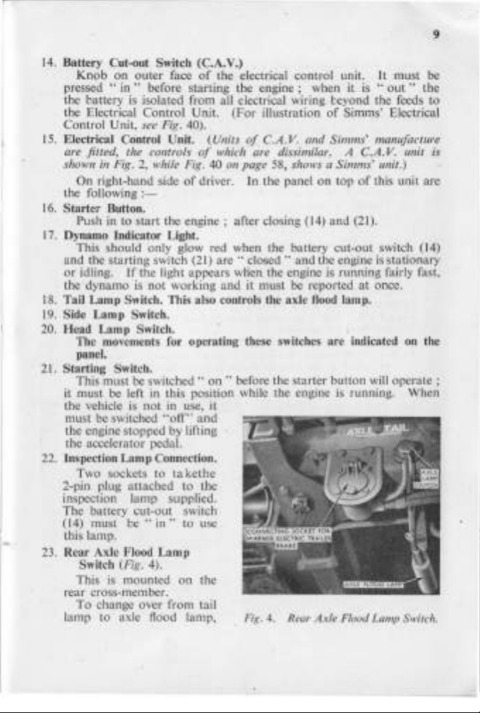
23.
Rear Axle Flood
rear cross-member.
lamp to axle flood lamp,
on
..
in"
Unit, see Fig. 40).
in
Fig. 2, while Fig. 40
On
right-hand side
Push in to start the
This should only glow red when the battery cut-out switch (14)
idling.
The movements for operating these switches are indicated on the
panel.
Switch.
This must be
Two sockets to
Switch (Fig. 4).
This
is
mounted
To change over from tail
outer face
before
is
isolated from all electrical wiring ceyond the feeds to
:-
If
the light appears when the engine
is
not
switched"
is
not
be"
in"
of
the electrical control unit.
s~arting
Unit.
of
engine;
working and it must be reported
in use, it
"off"
ta
kethe
to use
Lamp
on
the
engine;
(For
illustration
of
of
which are dissimilar. A
driver.
are"
on
and
the
C.AY.
on
page 58, shows a Simms' unit.)
In
the panel
after closing (14) and (21).
closed"
" before the starter button will
Fig. 4. Rear
when it
and Simms' manufacture
on
and
Axle
It
is
"out"
of
Simms' Electrical
C.AY.
top
of
this unit are
the engine
is
is
running fairly fast.
is
Flood Lamp Switch.
stationary
at
once.
running. When
must be
operate;
9
the
unit is
10
move the lever to the
left;
to cut
tail lamp, move lever to the right.
The switch
"
on
be
marked"
tail"
" for either the axle lamp
INSTRUMENTS.
On
the instrument panel
just
mounted the following instruments :-
24.
Oil Pressure Gauge.
This registers lubricating oil pressure,
engine.
It
should read
60
lb.jsq. inch when the engine
the maximum governed speed
25.
Air Pressure Gauge.
This indicates
It
should normally read between
or
95
26
. Speedometer.
and 100 lb. /sq. inch (Clayton-Dewandre) (See
This registers the speed
Note.-Early
the
amount
vehicles
of
the vehicle
had
additional gauges showing the Radiator
water and Engine oil temperatures.
27. Instrument Panel Light Switch.
28. Horn Push. This is mounted
29.
Warner Brake Controller.
Although ilJustrated
front dash
it
is mounted
Fig. 31).
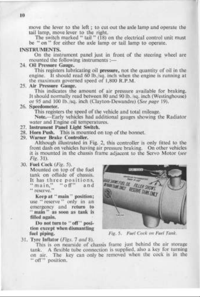
30.
Fuel Cock (Fig. 5).
Mounted
tank
on offside
It
has
three
"main,"
on
vehicles having air pressure braking.
in
on
top
positions,
"off"
in
Fig.
the chassis frame adjacent to the Servo
of
the fuel
of
chassis.
and
" reserve."
Keep
at"
"
use
emergency
"
main"
main " position;
reserve"
only
and
as soon as tank
in
an
return to
is
filled again.
Do not turn to
tion except
when
"oft'''
posi-
dismantling
fuel piping.
3
J.
Tyre Inflator (Figs. 7
This
is
on
nearside
and
8).
of
chassis frame just behind the air storage
tank. A flexible tube connection
on
air. The key can only be removed when the cock
"
off"
position.
out
the axle lamp and operate the
(18)
on
the electrical control unit must
or
tail lamp to operate.
in front
of
J ,800 R.P.M.
of
air pressure available for braking.
80
on
top
2,
this controlJer
and 90
and
of
the bonnet.
of
the steering wheel are
not
the quantity
of
is
Ib.
/sq. inch (Westinghouse)
page
19).
total mileage.
is
only fitted to the
On
other vehicles
oil in the
running
Motor
Fig.
5.
Fu
el Cock on Fuel Tank.
is
supplied, also a key for turning
is
at
(see
in the

11
ENGINE STARTING AND DRIVING
INSTRUCTIONS.
A.
Before Starting the Engine, see
(i)
Radiator
is within 1 in. below the level
(ii)
Oil
(iii)
Fuel
(iv)
Main
The
oil level in the sump should be maintained as near
mark
as possible as this results in lower oil temperatures
lubricating qualities.
B. To
Start
(i) Close the battery cut-out switch (14), Fig.
(ii) Move the starting switch (21) to
(iii) Depress the accelerator pedal fully.
(iv)
Press the starter
(v) Release starter
starter running as
engine to come to rest, then begin again.
found necessary
depressed for a few moments after the engine starts,
as it has warmed
(vi) Immediately the engine starts, check the reading
gauge;
higher
(idling) as the oil warms up.
If
C. To
Start
When temperatures are sufficiently low to call for the use
starting device, the felt element in the main fuel filter must be exchanged
for the brass wire gauze type (carried
starting device)
is full
of
water, or,
in
the engine sump
tank
is full
and
change speed lever
the Engine (Temperatures above
button
button
If
the engine does not pick
it should be approximately 60 [b./sq. inch.
if
temperature is low, but may reduce to
the engine fails to
the Engine (Temperatures near
(see page 34), then proceed as follows
to
to
keep the accelerator pedal more
up
that:
if
anti-freeze solution
of
the
top
rim
of
is
up
to the
top
mark
cock is
do so will exhaust the
in " main"
is
in
neutral position.
(16) firmly.
as
soon
up
position.
16
deg. F.).
2.
the"
on
" position.
as the engine starts.
in a
few
seconds,
battery;
It will sometimes be .
slightly this will
start,
vent the fuel system (see page 34).
not
be necessary.
or
below
16
on
vehicles equipped with Ether
:-
is
the gauze strainer.
of
of
in use, it
the dipstick.
to
the full
and
higher
do
not
keep
wait for the
or
less fully
but
as soon
the oil pressure
It
25
deg.
will be
lb. /sq. inch
F.)
.
of
the Ether
the
12
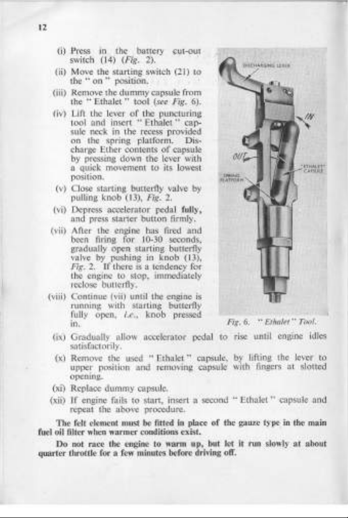
(i) Press in
th~
battery
f.:ut-oUI
switch (14) (Fig. 2). '
(ii) Move the starting switch (21) to
"
on"
the
position.
(iii) Remove the dummy capsule from
"Ethalet
the
(iv) Lift the lever
tool and insert
" tool (see Fig. 6).
of
the puncturing
"Ethalet"
cap-
sule neck in the recess provided
on the spring platform. Dis-
of
charge Ether contents
capsule
by pressing down the lever with
to
a quick movement
its lowest
position.
(v)
Close starting butterfly valve
by
pulling knob (13), Fig. 2.
(vi) Depress accelerator pedal fully,
button
and press starter
(vii) After the engine has fired
firmly.
and
been firing for 10-30 seconds,
gradually open starting butterfly
valve by pushing in knob (13),
Fig. 2.
If
there
is
a te'ndency for
the engine to stop, immediately
reclose butterfly.
(viii) Continue (vii) until the engine
is
running with starting butterfly
fully open,
in.
i.e., knob pressed
Fig.
6.
"Ethalet
" Tool.
(ix) Gradually allow accelerator pedal to rise until engine idles
satisfactorily.
(x) Remove the used
upper position
and
"Ethalet"
removing capsule with fingers
capsule,
by
lifting the lever to
at
opening.
(xi) Replace dummy capsule.
If
(xii)
engine fails to start, insert a second "
Ethalet"
capsule
repeat the above procedure.
The felt element must be fitted in place
of
the gauze type in the main
fuel oil filter when warmer conditions exist.
Do not race the engine to warm up, but let
it
fun slowly
quarter throttle for a few minutes before driving off.
slotted
at
about
and
13
When starting from cold in frosty weather, see
is in position
flap will permit the vehicle
temperatures
to
operate
is
D.
To
Lift the accelerator pedal with the toe,
until the engine stops.
Stop
on
the lower
up
to
90"
in
tropical climates.
the Engine.
F.,
portion
to
it
of
operate satisfactorily
should only be removed
GENERAL HINTS ON DRIVING.
(i)
For
normal
road
drive,
i.
"
(ii) Start in 2nd "
Do
(iii)
hold the clutch
Use " top"
(iv)
while
hills,
changing down.
(v)
Do
low gear, change
The
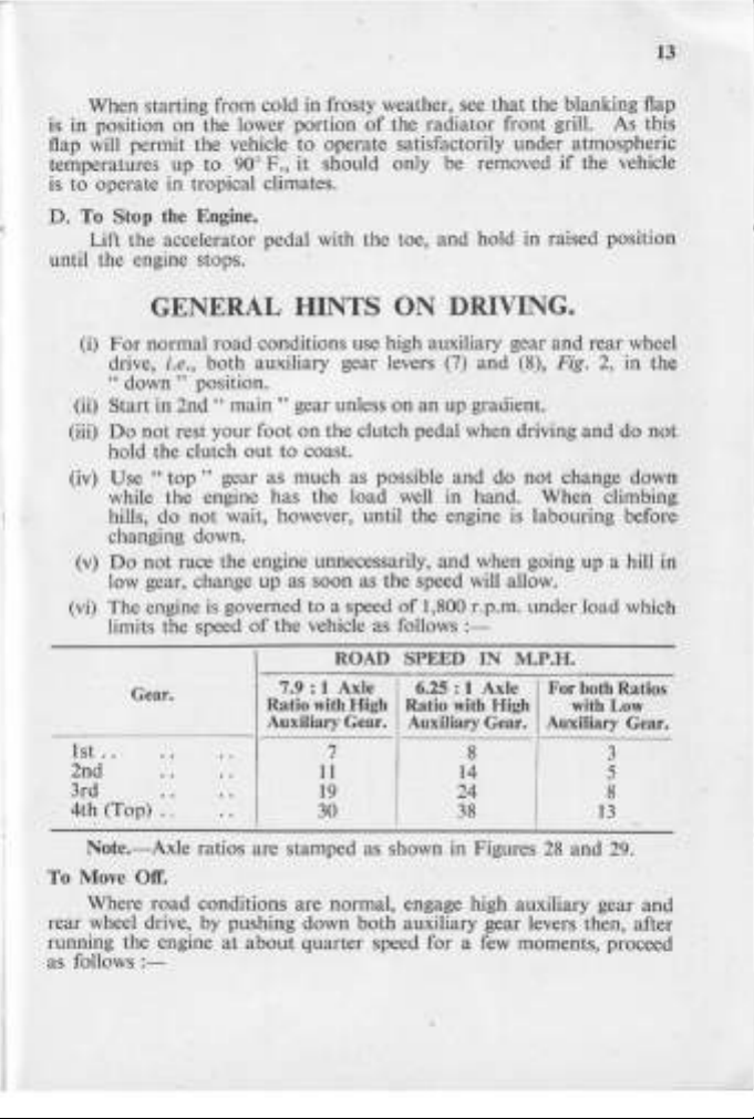
(vi)
limits the speed
1st
..
2nd
3rd
4th (Top)
Note.-Axle
To Move
Where
rear wheel drive, by pushing down
running the engine
as follows :-
e., both auxiliary gear levers (7)
down"
not
rest
the
do
not
not
race the engine unnecessarily,
engine is governed to a speed
Gear.
· . · .
· .
· . · .
"
Off.
road
conditions use high auxiliary gear
position.
main"
gear unless
your
foot
on
out
gear as
engine
wait, however, until the engine is labouring before
up
of
· .
· .
ratios are stamped as shown in Figures
conditions
at
about
the clutch pedal when driving
to
coast.
much
has
the vehicle as fa
7.9:
Ratio
Auxiliary Gear.
as possible
the load well in hand.
as
soon
as the speed will allow.
ROAD SPEED
1 Axle 6.25: 1 Axle
with
High Ratio
7
11
19
30
are
normal, engage high auxiliary gear
both
quarter
speed for a few moments, proceed
that
the
radiator
and
on
an
up gradient.
and
and
of
1,800 r.p.m.
Haws
:-
with
Auxiliary Gear.
14
24
38
auxiliary gear levers then, after
the blanking flap
front grill. As this
under
atmospheric
if
the vehicle
hold
in raised position
and
rear
and
load
with
13
and
wheel
do
down
climbing
which
Low
3
5
8
29.
and
(8), Fig. 2, in the
do
not
change
When
when going up a hill in
under
IN
M.P.H.
For both Ratios
High
Auxiliary Gear.
8
28
not
and
14
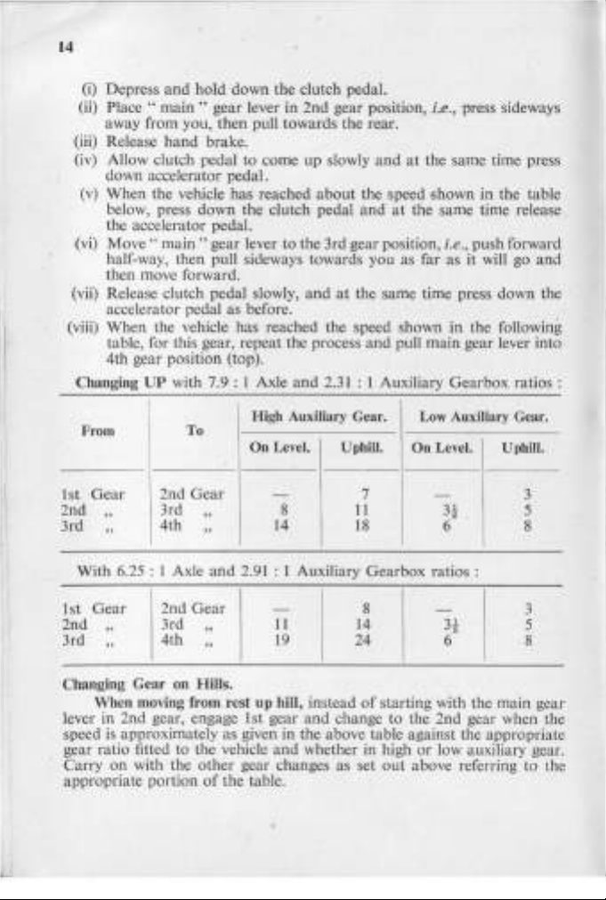
(i) Depress
(ij)
Place"
and
hold down the clutch pedal.
main"
gear lever in 2nd gear position, i.e., press sideways
away from you, then pull towards the rear.
hand
(iii) Release
(iv) Allow clutch pedal to come up slowly
brake.
and
at
the same time press
down accelerator pedal.
(v)
When the vehicle has reached
below, press down the clutch pedal
about
the speed 5hown in the table
and
at
the same time release
the accelerator pedal.
(vi)
Move"
main"
gear lever to the 3rd gear position, i.e., push forward
half-way, then pull sideways towards you as far as it will go
then move forward.
(vii) Release clutch pedal slowly,
and
at
the same time press down the
accelerator pedal as before.
(viii) When the vehicle has reached the speed shown
and
table, for this gear, repeat the process
pull main gear lever into
4th gear position (top).
Changing
From
1st
2nd
3rd
With 6.25 : 1 Axle
Gear
"
"
UP
with 7.9 : 1 Axle
To
\ 2nd
Gear
3rd "
14th
"
and
and
2.31
: 1 Auxiliary Gearbox
High Auxiliary Gear.
On
Level.
- 7
8
14
2.91
: 1 Auxiliary Gearbox ratios :
UphiU.
11
18
Low
On
in
the following
ratios:
Auxiliary Gear.
Level.
- 3
Uphill.
3t
6 8
and
5
1st
2nd
3rd
Gear
"
"
3rd
4th
Gear
"
"
-
I
11
19
8
14
24
I
2nd
Changing Gear on Hills.
When moving from rest up hill, instead
lever in 2nd gear, engage 1st gear
speed
is
approximately as given
in
and
the above table against the appropriate
of
starting with the main gear
change to the 2nd gear when the
gear ratio fitted to the vehicle and whether in high
on
Carry
with the
appropriate portion
other
gear changes as set
of
the table.
out
-
3!
3
5
6 8
or
low auxiliary gear.
above referring to the
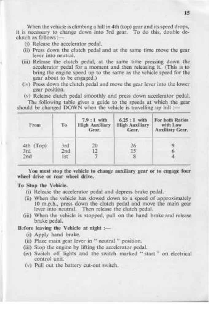
15
When the vehicle
is
necessary to change down into 3rd gear.
it
clutch as follows
(i)
Release the accelerator pedal.
(ii) Press down the clutch pedal
is
:-
climbing a hill
in
4th (top) gear
and
at
the same time move the gear
and
To
do this, double de-
lever into neutral.
(iii) Release the clutch pedal,
accelerator pedal for a moment
at
the same time pressing down the
and
then releasing it. (This is to
bring the engine speed up to the same as the vehicle speed for the
about
gear
(iv) Press down the clutch pedal
to be engaged.)
and
move the gear lever into the lower
gear position.
(v)
Release clutch pedal smoothly
The following table gives a guide to the speeds
should be changed
DOWN
when the vehicle
7.9: 1 with
From
High Auxiliary High Auxiliary
To
Gear. Gear.
4th (Top) 3rd
3rd
2nd 12
2nd 1st
You must stop the vehicle to change auxiliary gear
and
press down accelerator pedal.
at
is
travelling
6.25: 1
with
20 26
15
7 8 4
or
wheel drive or rear wheel drive.
Stop the Vehicle.
To
(i) Release the accelerator pedal
(ii) When the vehicle has slowed down to a speed
10
m.p.h., press down the clutch pedal
and
depress brake pedal. '
and
of
move the
lever into neutral. Then release the clutch pedal.
(iii) When the vehicle
is
stopped, pull
on
the
hand
brake
brake pedal.
B~fore
leaving the Vehicle
(i)
Appl/
hand
(ii) Place main gear lever
brake.
at
night
:-
in " neutral"
position.
(iii) Stop the engine by lifting the accelerator pedal.
(iv) Switch off lights
and
the switch marked
"start"
control unit.
(v) Pull
out
the battery cut-out switch.
its speed drops,
which the gear
up
hill
:-
For
both
Ratios
with
Low
Auxiliary Gear.
9
6
to engage four
approximately
main
gear
and
release
on
electrical
16
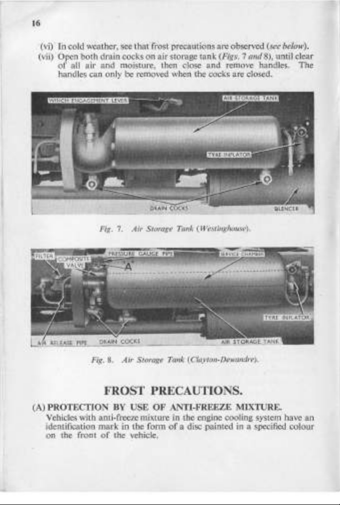
(vi) In cold weather,
See
thatCrost precautions are observed (see below).
(vii) Open both drain cocks on air storage tank (Figs. 7
of
all air and moisture, then close
and
remove handles. The
handles can only be removed when the cocks are closed.
Fig. 7. Air Storage Tank (Westinghouse).
and
8),
until clear
8.
Air
Fig.
Storage Tank (Clayton-Dewandre).
FROST PRECAUTIONS.
(A)
PROTECTION
Vehicles with anti-freeze mixture in the engine cooling system have
identification
on
the front
BY
mark
of
the vehicle.
USE
in
the form
OF
ANTI-FREEZE MIXTURE.
of
a disc painted in a specified colour
an
17
If
your vehicle
(i)
Do not drain the cooling system unless instructed to do so.
(ii)
If
the cooling system has to
number
mixture for re-use (approximately 6 gallons).
(iii)
Top
when the engine is hot.
Top
(iv)
over-fill.
(v)
If
for any reason the mixture
water, paint out the coloured disc.
Brake Anti-freezer:
and various other units in the air pressure system, from freezing in severe
weather, the anti-freezer fitted
filled
with"
are ordered,
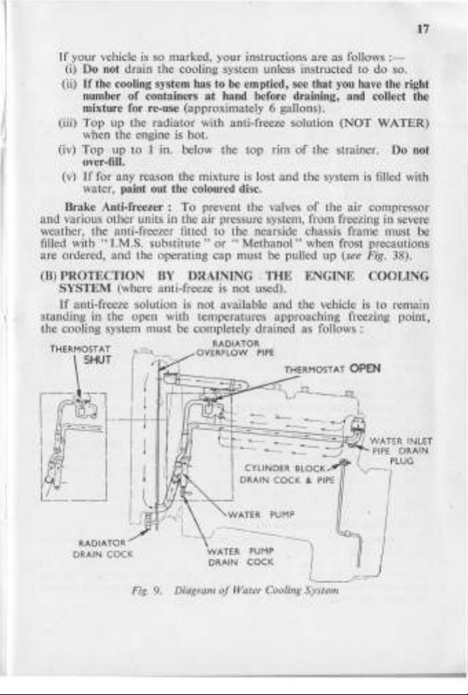
(B)
PROTECTION
SYSTEM
If
anti-freeze solution
standing
the cooling system must be completely drained as follows:
THERMOSTAT
in
SHUT
is
so marked, your instructions are as follows :-
be
of
containers
up
the radiator with anti-freeze solution
up to 1 in. below the
To
prevent the valves
I.M.S.
wbstitute"
and
the operating cap must be pulled up (see Fig. 38).
BY
(where anti-freeze is
the open with temperatures approaching freezing point,
DRAINING .
is
not
OVERFLOW
emptied, see that you have the right
at
hand before draining, and collect the
(NOT
WATER)
top
rim
of
the strainer. Do not
is
lost and the system
of
to
the nearside chassis frame must be
or
"Methanol"
not
available
RADIATOR
used).
PIPE
when frost precautions
THE
ENGINE COOLING
and
the vehicle is
is
filled with
the air compressor
to
remain
RADIATOR
DRAIN
COCK
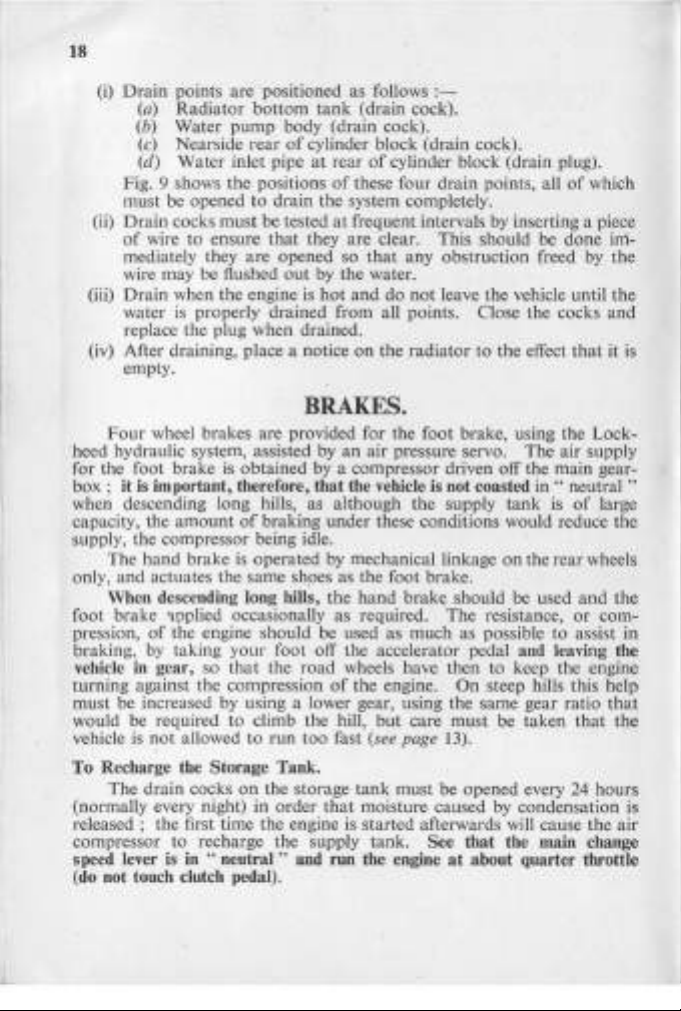
Fig
. 9. Diagram
Mr~~=$~~~
I
I
- CYLINDER
DRAIN
~~~~~
___
- .
BLOCK
COCK & PIPE
~
WATER
PUMP
DRAIN
COCK
of
Water Cooling System
~"WATER
(
V--,
PIPE
DRAIN
PLUG
INLET
I
18
(i)
Drain
points are positioned as follows
(a)
Radiator
(b) Water pump body (drain cock).
(c)
Nearside
(d)
Water inlet pipe
Fig. 9 shows
must be opened
(ii)
Drain
cocks
of
wire
to
rear
the
to
must
ensure
bottom
tank
of
cylinder block (drain cock).
at
positions
drain the system completely.
be tested
that
they are clear. This should be done immediately they are opened so
wire may be flushed
(iii)
Drain
when the engine
is
water
properly drained from all points . Close the cocks
out
by the water.
is
hot
(drain cock).
rear
of
of
these four drain points, all
at
frequent intervals by inserting a piece
that
and
:-
cylinder block (drain plug).
of
any obstruction freed by the
do
not
leave the vehicle until the
which
and
replace the plug when drained.
(iv) After draining, place a notice
on
the
radiator
to
the effect
that
it
empty.
BRAKES.
Four
heed hydraulic system, assisted by
wheel brakes are provided for the foot brake, using the Lock-
for the foot brake is obtained
box ;
it
is important, therefore, that the vehicle is not coasted
when descending long hills, as although the supply
capacity, the
amount
of
braking under these conditions would reduce the
supply, the compressor being idle.
The hand brake
and
only,
actuates the same shoes as the foot brake.
is
operated
When descending long hills,
foot brake
pression,
braking, by taking
vehicle in gear, so
'lpplied occasionally as required. The resistance,
of
the engine should be used as much as possible to assist in
your
foot off the accelerator pedal and leaving the
that
the
turning against the compression
by
must be increased
would be required
vehicle is
not
allowed
using a lower gear, using the same gear ratio
to
climb the hill,
to
run
To Recharge the Storage Tank.
The
(normally every night)
drain cocks
on
the storage
in
order
released; the first time the engine is started afterwards will cause the air
compressor to recharge the supply tank.
"
speed lever is in
(do not touch clutch
neutral"
pedal).
an
air pressure servo.
by
a compressor driven off the main gear-
The
in " neutral"
tank
by
mechanical linkage
the
hand
brake should be used
road
wheels have then to keep the engine
of
the engine.
but
too
fast (see
that
care
page
tank
must be opened every 24 hours
moisture caused by condensation
on
the rear wheels
On
steep hills this help
must
be taken
13).
See that the main change
and run the engine
at
about quarter throttle
air supply
is
of
large
and
or
com-
that
that
the
the
is
is
19
During
gauge will rise to
2 minutes until
pressure.
a valve will operate with a hiss, indicating
the compressor will then automatically
With the Clayton
gauge
which the engine starts
which the gauge will rise steadily until approximately
is
reached.
Get
The
charging with the Westinghouse system, the
65 lb./sq. inch
both
The
compartments
gauge will
Dewandre
at
65
lb./ sq. inch,
and
used to the feel
air
pressure gauge must show
but
of
and
will remain
of
then
rise
the supply
to
approximately 90 lb. /sq. inch when
run
light. .
system
no
there will be a pause between the
when the gauge commences
the brakes as soon as possible.
at
at
this figure
tank
reach the same
that
the system is
pause takes place
air
to
register, after
100 lb. /sq. inch
least 75 lb. /sq. inch before
driving the vehicle.
of
Before getting out
your seat to leave the vehicle, always apply the.
hand brake.
USE OF WINCH.
The winch may be used for unditching the vehicle to which it is
fitted by attaching the winch cable
tractor
either
to
skid
It
may
pans
the front
also be used
provided
or
for
must
ditched vehicle, as shown in Fig.
Payout
To
(i) See
(ii)
(iii) See
(iv)
the Cable.
that
the winch engagement lever, which is
auxiliary gearbox
"
out"
position.
See
that
the winch
that
the winch clutch lever is in
The
winch
hand. Never
drum
payout
at
is
After the cable has been payed
allow another vehicle to pass over
which interfere with the proper winding on the drum.
To
Pull in the Cable.
(i) Place
(ii) Move
the
main
gear lever
the
gear lever in "
in
the"
winch engagement lever, which is
auxiliary gearbox
direction
to
engage
winch"
at
the
to
a suitable anchorage
in
line with the
the rear.
unditching a second vehicle, in which case the
be placed under the front wheels
10,
to
ensure sufficient hold.
mounted
the nearside
brake
is " off."
now
free
of
the chassis, is back in the
the"
up
" position in its clip.
and
the cable may be pulled
by driving the winch in reverse.
out
and
is lying
on
it
as
this will cause kinks in the cable
neutral"
and
the ground , never
the outside auxiliary
position.
mounted
the nearside
of
the chassis,
in
winch drive.
pressure
for
about
charged;
on
the
moment
of
the
on
out
on
at
Ull-
the
by
the
a forward
 Loading...