

Page 1

HE • CHE • BCHE
Mass Flow Series
Drying Hoppers
AEC, Inc.
801 AEC Drive
Wood Dale, IL 60191-1198
Tel (630) 595-1060
Fax (630) 595-6641
Part No. A0548656 Revision A Bulletin No. WH1-630B
Page 2

Performance figures stated in this manual are based on a standard atmosphere of 59°F
(15°C) at 29.92” Hg (1,014 millibars) at sea level, using 60 hz power. Altitude is an
important consideration when specifying dryer components. AEC/Whitlock can advise
you on proper selection and sizing of systems for your operating environment.
AEC/Whitlock is committed to a continuing program of product improvement.
Specifications, appearance, and dimensions described in this manual
are subject to change without notice.
© Copyright AEC/Whitlock and AEC, Inc. 2011
All rights reserved. Effective 4/13/2011
Part No. A0548656 Revision A Bulletin No. WH1-630B.1
Page 2 HE • CHE • BCHE Mass Flow Series Drying Hoppers
Page 3

Please note that our address and phone information has changed.
Please reference this page for updated contact information.
These manuals are obsolete and are provided only for their technical information, data and capacities.
Portions of these manuals detailing procedures or precautions in the operation, inspection, maintenance
and repair of the products may be inadequate, inaccurate, and/or incomplete and shouldn’t be relied
upon. Please contact the ACS Group for more current information about these manuals and their
warnings and precautions.
Parts and Service Department
The ACS Customer Service Group will provide your company with genuine OEM quality parts manufactured to engineering
design specifications, which will maximize your equipment’s performance and efficiency. To assist in expediting your phone
or fax order, please have the model and serial number of your unit when you contact us. A customer replacement parts list
is included in this manual for your convenience. ACS welcomes inquiries on all your parts needs and is dedicated to
providing excellent customer service.
For immediate assistance, please contact:
• North, Central and South America, 8am – 5pm CST +1 (800) 483-3919 for drying, conveying, heating and cooling
and automation. For size reduction: +1 (800) 229-2919.
North America, emergencies after 5pm CST (847) 439-5855
North America email: acsuscanadacustserv@corpemail.com
• Mexico, Central & South America
Email: acslatinamericacustserv@corpemail.com
• Europe, Middle East & Africa +48 22 390 9720
Email: acseuropecustserv@corpemail.com
• India +91 21 35329112
Email: acsindiacustserv@corpemail.com
• Asia/Australia +86 512 8717 1919
Email: acsasiacustserv@corpemail.com
Sales and Contracting Department
Our products are sold by a worldwide network of independent sales representatives. Contact our Sales Department for the
name of the sales representative nearest you.
Let us install your system. The Contract Department offers any or all of these services: project planning; system packages
including drawings; equipment, labor, and construction materials; and union or non-union installations.
For assistance with your sales or system contracting needs please Call:
North, Central and South America +1 (262) 641-8600 or +1 (847) 273-7700 Monday–Friday, 8am–5pm CST
Europe/Middle East/Africa +48 22 390 9720
India +91 21 35329112
Asia/Australia +86 512 8717 1919
Facilities:
ACS offers facilities around the world to service you no matter where you are located. For more information, please visit us at
www.acscorporate.com
United States:
ACS Schaumburg – Corporate Offices
1100 E. Woodfield Road
Suite 588
Schaumburg, IL 60173
Phone: + 1 847 273 7700
Fax: + 1 847 273 7804
ACS New Berlin – Manufacturing Facility
2900 S. 160th Street
New Berlin, WI 53151
Phone : +1 262 641 8600
Fax: + 1 262 641 8653
Asia/Australia:
ACS Suzhou
109 Xingpu Road SIP
Suzhou, China 215126
Phone: + 86 8717 1919
Fax: +86 512 8717 1916
Europe/Middle East/Africa:
ACS Warsaw
Ul. Działkowa 115
02-234 Warszawa
Phone: + 48 22 390 9720
Fax: +48 22 390 9724
India
ACS India
Gat No. 191/1, Sandbhor Complex
Mhalunge, Chakan, Tal Khed,
Dist. Pune 410501, India
Phone: +91 21 35329112
Fax: + 91 20 40147576
Page 4

Safety Considerations
AEC/Whitlock HE, CHE, and BCHE Mass Flow Series drying hoppers are designed to provide
safe and reliable operation when installed and operated within design specifications, following
national and local safety codes.
To avoid possible personnel injury or equipment damage when installing, operating, or
maintaining this equipment, use good judgment and follow these safe practices:
; Follow all SAFETY CODES.
; Wear SAFETY GLASSES and WORK GLOVES.
; Disconnect and/or lock out power before servicing or maintaining the dryer.
; Use care when LOADING, UNLOADING, RIGGING, or MOVING this equipment.
; Operate this equipment within design specifications.
; OPEN, TAG, and LOCK ALL DISCONNECTS before working on this equipment. You
should remove the fuses and carry them with you.
; Make sure the dryer and components are properly GROUNDED before you switch on
power.
; Do not jump or bypass any electrical safety control.
; Do not restore power until you remove all tools, test equipment, etc., and the dryer and
related equipment are fully reassembled.
; Only PROPERLY TRAINED personnel familiar with the information in this manual should
work on this equipment.
HE • CHE • BCHE Mass Flow Series Drying Hoppers Page 3
Page 5

Table of Contents
1 General Information ................................................. 7
1-1 Introduction
1-2 Equipment Function
1-3 The HE Heater Drying Hopper Package
1-4 The CHE Control and Heater Drying Hopper Package
1-5 The BCHE Blower Controls Heater Drying Hopper Package
2 Shipping Information ............................................. 11
2-1 Unpacking and Inspection
2-2 In the Event of Shipping Damages
2-3 If the Shipment is Not Complete
2-4 If the Shipment is Not Correct
2-5 Returns
3 Installation ............................................................... 13
3-1 Work Rules
3-2 Necessary Documents
3-3 Installing Machine-Mount Drying Hoppers
3-4 Installing Floor-Mount Drying Hoppers
3-5 Making Hose Connections
3-6 Making Electrical Connections
3-7 Checking for Proper Blower Rotation
4 Startup, Shutdown, and Operation ....................... 21
4-1 Pre-Startup Checklist
4-2 Starting the Process
4-3 Shutting Down the Process
Page 4 HE • CHE • BCHE Mass Flow Series Drying Hoppers
Page 6

Table of Contents
5 1/4 DIN Controllers ................................................. 25
5-1 Graphic Panel for 1/4 DIN Controller
5-2 Using the 1/4 DIN Temperature Controller
5-3 Using Temperature Controller Internal Switches
5-4 Using the Temperature Controller Anti-Tamper Lockout Switch
5-5 Changing the Display from Fahrenheit to Celsius
5-6 Setting the Process Air Temperature
5-7 Setting the High Temperature Alarm
5-8 Activating the Auto-Tune Function
5-9 Restoring the Controller to Factory Setup
6 1/16 DIN Controllers ............................................... 35
6-1 Graphic Panel for 1/16 DIN Controller
6-2 Using the 1/16 DIN Temperature Controller
6-3 Setting the Process Air Temperature on the 1/16 DIN Controller
6-4 Setting the High Temperature Alarm on the 1/16 DIN Controller
6-5 Restoring the 1/16 DIN Temperature Controller to Factory Setup
7 Maintenance ............................................................ 47
7-1 Work Rules
7-2 Cleaning Out the Drying Hopper
7-3 Replacing the Process Heater
7-4 Servicing Process Air Filters
8 Troubleshooting ..................................................... 53
HE • CHE • BCHE Mass Flow Series Drying Hoppers Page 5
Page 7
Charts and Figures
1
Typical HE Drying Hopper Package 8
2
Typical CHE Drying Hopper Package 9
3
Typical BCHE Drying Hopper Package 10
4
Machine Mounting Flange Dimensions 15
5
Drying Hopper Cover Bolt Patterns 16
6
Typical Single Hopper Drying Hose Installation 18
7
Typical Multiple Hopper Drying Hose Installation 19
8
Component Identification Exploded View 23
9
10
11
12
13
14
15
16
17
18
Graphic Panel for 1/4 DIN Controller 25
1/4 DIN Controller 26
1/4 DIN Temperature Controller Preset Parameters 32
Self-Diagnostic Error Messages 34
Graphic Panel for 1/16 DIN Controller 35
1/16 DIN Controller 37
Display Readout for Mode Settings 42
Default Setting List for 1/16 DIN Process Temperature Controller:
Protect / Level / Setup / Expansion
Available Board Options 46
Recommended Spare Parts List 51
43-45
Page 6 HE • CHE • BCHE Mass Flow Series Drying Hoppers
Page 8

1 General Information
1-1 Introduction
AEC/Whitlock HE (Heaters), CHE (Controls and Heaters), and BCHE (Blower, Controls and
Heaters) Mass Flow Series drying hopper packages offer a high efficiency alternative for drying
multiple materials when used with a single or multiple dryer(s).
1-2 Equipment Function
AEC/Whitlock HE, CHE, and BCHE Mass Flow Series drying hoppers are used in conjunction
with a dehumidifying dryer unit. This dryer/drying hopper system generates heated,
dehumidified air to dry hygroscopic materials, such as plastic pellets. As in standard drying
systems, this operation removes moisture from the process air via molecular sieve desiccant beds
in the dehumidifying dryer unit. The system then sends this dry air to the HE, CHE, or BCHE
drying hopper, where heating elements are located. Heating the air at the drying hopper cuts
energy waste otherwise caused by heated air flowing through the dryer hose. After the system
heats air at the inlet of the drying hopper, it passes through the column of plastic resin in the
hopper and then returns to the dehumidifying dryer unit.
The drying hopper is designed to promote even drying and uniform material flow by using a
unique air/material diffuser cone. It is of modular construction, and can be configured and
oriented in numerous ways. You can easily change diameters on the process air inlet and outlet
with hand tools.
Material moves through the hopper in a first in, first out flow pattern. Located in the cover, the
removable air trap prevents introduction of moist ambient air into the drying system. Other
features on your system include lifting lugs plus a sight glass to let you see the material level.
Various types of material take-off compartments and/or drawer magnets can be installed at the
discharge point of the hopper. Contact your AEC/Whitlock sales representative for selecting
companion equipment.
Drying hopper systems are sized to meet specific customer requirements. Sections on the
following few pages list the differences between HE, CHE, and BCHE drying hopper systems.
HE • CHE • BCHE Mass Flow Series Drying Hoppers Page 7
Page 9
1-3 The HE Heater Drying Hopper Package
The AEC/Whitlock HE drying hopper package offers a process air heater removed from the
dryer and mounted at the hopper with the temperature controller at the dryer. The HE drying
hopper package is designed for application where one dryer is delivering dehumidified air to one
drying hopper.
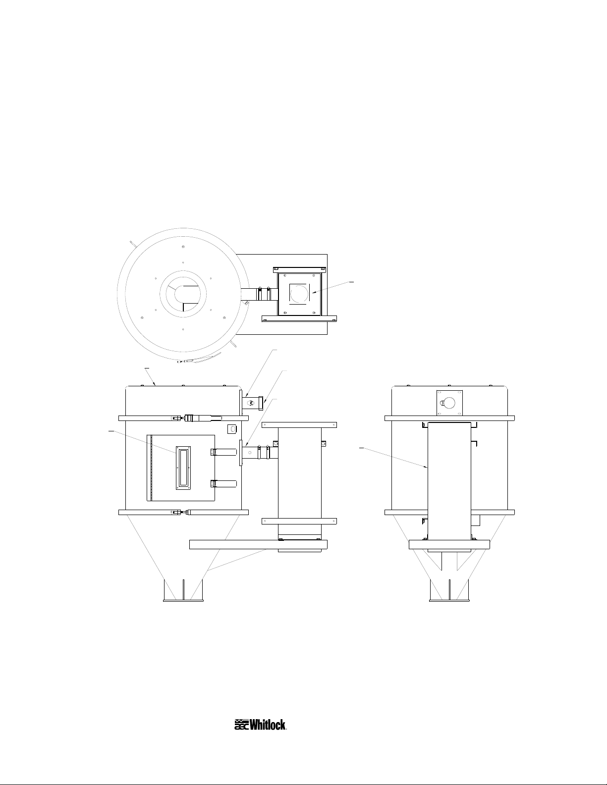
Figure 1
Typical HE Drying Hopper Package
Heater
Outlet transition
Sight
glass
Cover and air trap/diffuser
Return air outlet
Process air connection
Heater
Page 8 HE • CHE • BCHE Mass Flow Series Drying Hoppers
Page 10
1-4 The CHE Control and Heater Drying Hopper
Package
The AEC/Whitlock CHE drying hopper package offers a process air heater removed from the
dryer and mounted at the hopper. The temperature controller is mounted at or on the drying
hopper. The design of the CHE package allows the dryer to deliver dehumidified air to multiple
drying hoppers to promote drying of different resins at different temperatures in different
hoppers.
Note: The CHE hopper package uses separate power drops to each hopper and avoids feeding
high voltage power through the dryer. An interlock prevents operation of heaters on the
hopper when the dryer is not running.
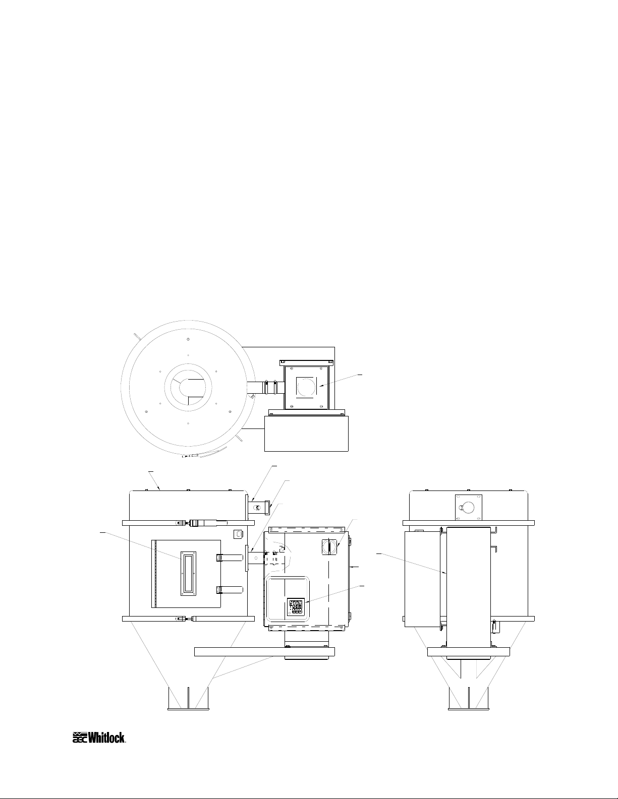
Figure 2
Typical CHE Drying Hopper Package
Heater
Sight
glass
Cover and air trap/diffuser
Outlet transition
Return air outlet
Process air connection
Disconnect
Heater
Control
panel
Temperature
controller
HE • CHE • BCHE Mass Flow Series Drying Hoppers Page 9
Page 11
1-5 The BCHE Blower Controls Heater Drying
Hopper Package
The AEC/Whitlock BCHE drying hopper package features a process air blower, heater and
controls for each hopper in your system. BCHE also offers a process air heater removed from the
dryer and mounted at the hopper. The temperature controller is mounted at or on the drying
hopper.
Important!
The main dryer may or may not have a process blower.
Check your drying system for specific options.
The BCHE drying hopper package design allows one dryer to generate dehumidified air for
multiple hoppers. Materials can be dried by a single dryer at different temperatures. BCHE can
also serve as a stand alone hot air dryer for non-hygroscopic materials when an optional ambient
air filter is installed to filter air entering the system.
Note: The BCHE package utilizes individual power drops to each hopper.
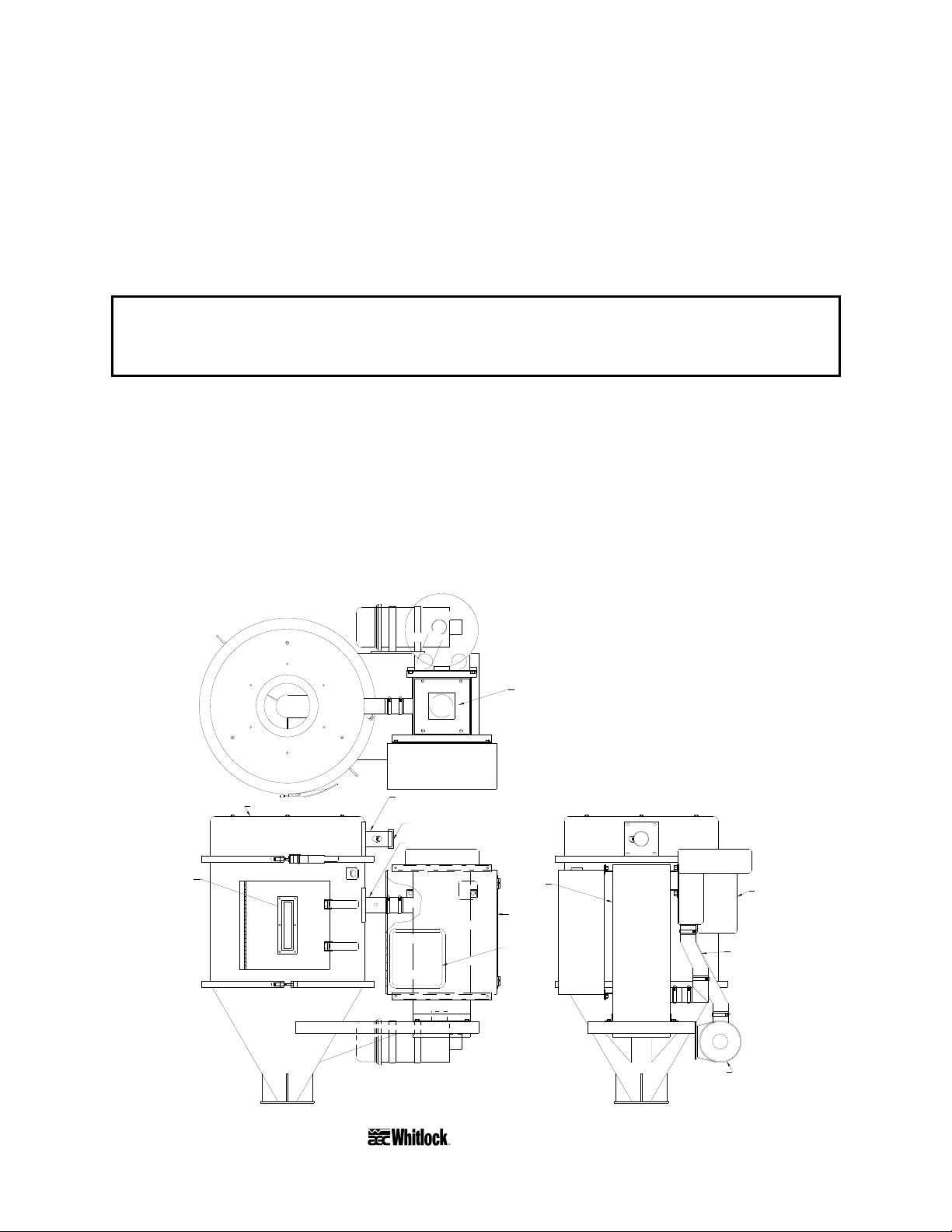
Figure 3
Typical BCHE Drying Hopper Package
Sight
glass
Cover and air trap/diffuser
Outlet transition
Return air outlet
Process air connection
Heater
Heater
Control
panel
Temperature
controller
Filter assembly/
process air inlet
Blower
2" high-temp
flex hose
Page 10 HE • CHE • BCHE Mass Flow Series Drying Hoppers
Page 12
2 Shipping Information
2-1 Unpacking and Inspection
You should inspect your AEC/Whitlock drying hopper unit for possible shipping damage. If the
container and packing materials are in re-usable condition, save them for reshipment, if
necessary.
Thoroughly check the equipment for any damage that might have occurred in transit, such as
broken or loose wiring and components, loose hardware and mounting screws, etc. In case of
breakage, damage, shortage, or incorrect shipment, refer to the following sections.
2-2 In the Event of Shipping Damages
Important!
According to the contract terms and conditions of the Carrier,
the responsibility of the Shipper ends at the time and place of shipment.
The Carrier then assumes full responsibility of the shipment.
; Notify the transportation company’s local agent if you discover damage.
; Hold the damaged goods and packing material for the examining agent’s inspection. Do not
return any goods to AEC, Inc. before the transportation company inspection and
authorization.
; File a claim against the transportation company. Substantiate the claim by referring to the
agent’s report. A certified copy of our invoice is available upon request. The original Bill of
Lading is attached to our original invoice. If the shipment was prepaid, write us for a
receipted transportation bill.
; Advise AEC, Inc. regarding your wish for replacement and to obtain an RMA (return
material authorization) number.
Parcel Post Shipment
; Notify AEC, Inc. at once in writing, giving details of the loss or damage. This information is
required for filing a claim with our insurance company.
; Hold the damaged goods with the container and packing materials for possible inspection by
postal authorities.
HE • CHE • BCHE Mass Flow Series Drying Hoppers Page 11
Page 13

United Parcel Service
; Contact your local UPS office regarding damage and insurance claims.
; Retain the container and packing.
; Notify AEC, Inc. at once.
2-3 If the Shipment is Not Complete
Check the packing list. The apparent shortage may be intentional. Back-ordered items are noted
on the packing list. You should have:
; AEC/Whitlock HE/CHE/BCHE Mass Flow Series drying hopper
; Bill of lading
; Packing list
; Operating and Installation packet
; Electrical schematic and panel layout drawings
; Component instruction manuals
Re-inspect the container and packing material to see if you missed any smaller items during
unpacking. Determine that the item was not inadvertently taken from the area before you
checked in the shipment. Notify AEC, Inc. immediately of the shortage.
2-4 If the Shipment is Not Correct
If the shipment is not what you ordered, contact AEC, Inc. immediately. Include the order
number and item. Hold the items until you receive shipping instructions.
2-5 Returns
Important!
Do not return any damaged or incorrect items
until you receive shipping instructions from AEC, Inc.
Page 12 HE • CHE • BCHE Mass Flow Series Drying Hoppers
Page 14

3 Work Rules
3-1 Work Rules
The installation, operation, and maintenance of this equipment must be conducted in accordance
with all applicable work and safety codes for the installation location. This may include, but is
not limited to, OSHA, NEC, CSA, and any other local, national and international regulations.
; Read and follow these operating instructions when installing, operating and maintaining this
equipment. If the instructions become damaged or unreadable, you can obtain additional
copies from AEC/Whitlock.
; Only qualified personnel familiar with this equipment should work on or with this
equipment.
; Work with approved tools and devices.
; Disconnect the electricity before maintenance or service.
; Always work from a stable, debris-free work platform.
; Remove any debris from the blower suction area.
3-2 Necessary Documents
The documents listed below are necessary for the operation, installation, and maintenance of
AEC/Whitlock drying hopper systems. Additional copies are available from AEC, Inc.
Familiarize the appropriate personnel with these documents:
• This manual.
• The electrical schematic included in the customer information packet.
• The Customer Spare Parts List included in the information packet.
• Operation and installation manuals for the dryer, optional controls or auxiliary equipment
in the drying system.
HE • CHE • BCHE Mass Flow Series Drying Hoppers Page 13
Page 15
3-3 Installing Machine-Mount Drying Hoppers
Note: Figure 5 on Page 16 shows typical mounting bolt patterns.
Important!
Do not mount the drying hopper where excessive vibration is present.
AEC, Inc. is not responsible for any damages caused by excessive vibration.
1. Determine which position the process air inlet, outlet, access door, drawer magnet (if so
equipped) and slide gate/dump spout should be oriented.
You can rotate the assembly 90º to fit your installation and provide a neat and efficient
installation.
2. Loosen the band clamps fastening the cylindrical section to the cover.
3. Orient the outlet in the direction of the return air line, and re-tighten band clamps.
Important!
Using a degreaser, remove rust inhibitor before using your drying hopper.
4. While the drying hopper is still bolted to the shipping pallet, install any needed vacuum
hoppers, hopper loaders, etc. on the cover. The bolt patterns are shown in Figure 3.
Note: AEC/Whitlock VH, PVH, and 99XX Series units with vacuum hoppers and hopper
loaders use covers with the keyhole cutout. AL, VF and TF series vacuum hoppers and
hopper loaders use the circular cutout covers.
Important!
Provide external support for all material conveying piping.
5. Check the flange bolt pattern on the machine the drying hopper is to be mounted on. If
the flange bolt patterns do not match, drill out the drying hopper mounting flange so they
match.
Note: A special flange adapter may be required if the bolt pattern does not mate properly.
Contact your AEC sales representative for more information.
6. Position the included slide gate flange on the processing machine mounting flange and
position the spacers on the slide gate flange so the spacers are parallel to the desired
direction of the slide gate. The slide gate itself can be installed after you secure the drying
hopper to the processing machine.
Note: Some drying hoppers may be equipped with an optional standard slidegate/premium
slidegate or drawer magnet.
Page 14 HE • CHE • BCHE Mass Flow Series Drying Hoppers
Page 16
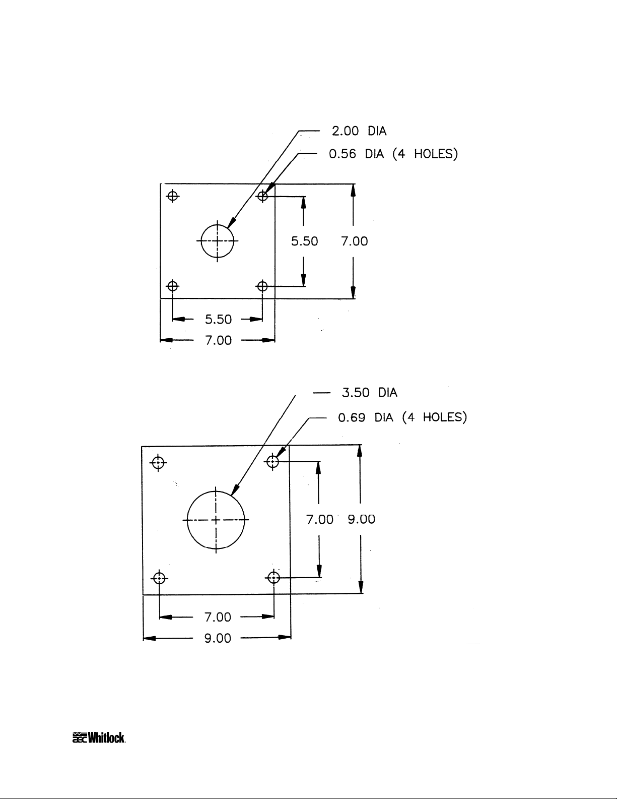
Figure 4
Machine Mounting Flange Dimensions
Mounting Flange Supplied With DH-1.5, DH-3.0, DH-4.0 & DH-6.0
Mounting Flange Supplied With DH-12.0, DH-17.0 & DH-23.0
HE • CHE • BCHE Mass Flow Series Drying Hoppers Page 15
Page 17
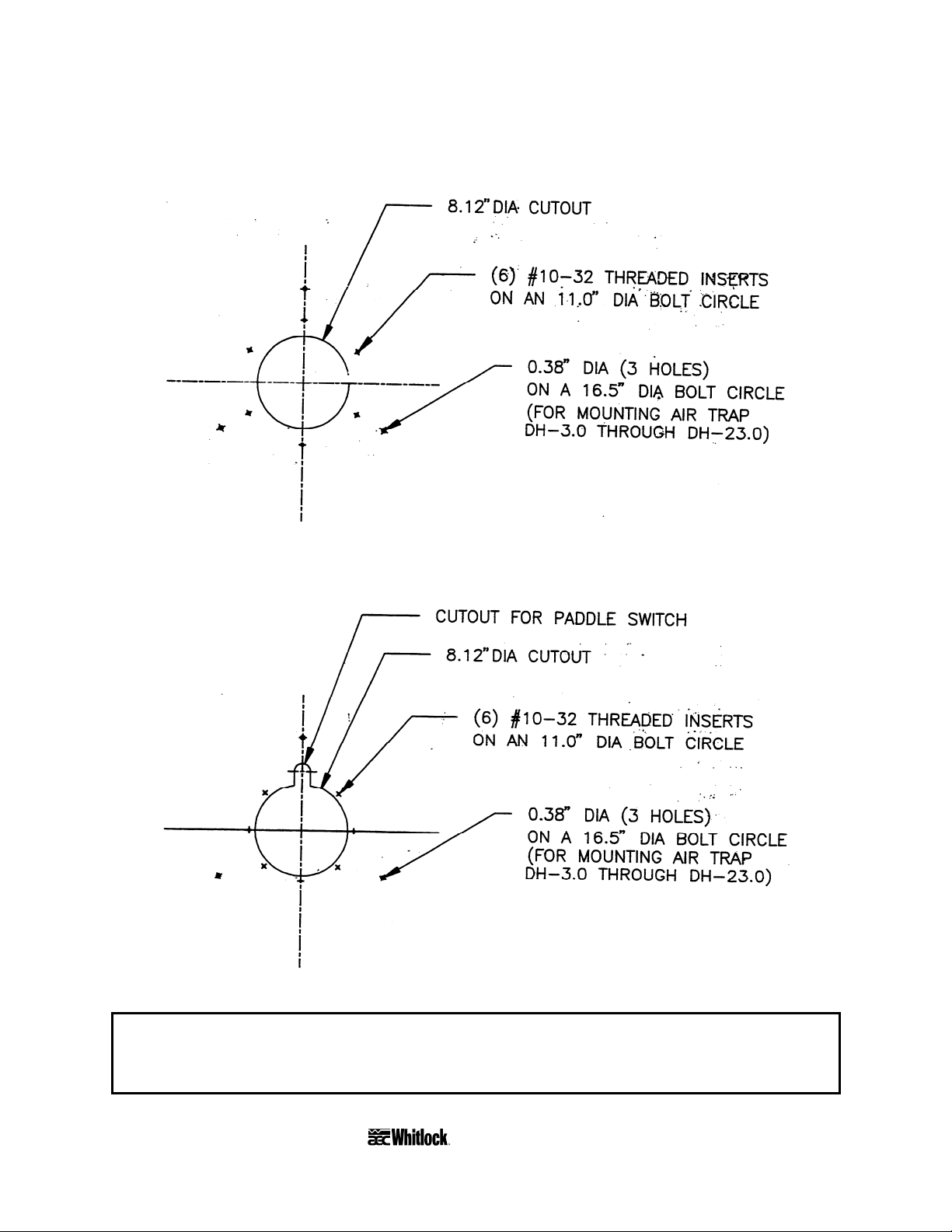
Figure 5
Drying Hopper Cover Bolt Patterns
Cover Cutout for AL, VF and TF Hopper Loaders and Vacuum Hoppers
Cover Cutout VH, PVH and 99XX Hopper Loaders and Vacuum Hoppers
Caution!
Make sure the band clamps are seated and tight and all other components
are secure before lifting the drying hopper from the shipping pallet.
Page 16 HE • CHE • BCHE Mass Flow Series Drying Hoppers
Page 18

7. Rig the empty drying hopper by the lifting lugs and install it on the processing machine.
8. Insert properly-sized bolts through the drying hopper flange, the slide gate spacers and
the processing machine flange. Fasten securely.
9. Insert the slide gate through the slot made by the slide gate spacers. The slide lip may be
installed up or down.
10. Screw the two retaining bolts provided into the portion of the slide gate exposed when the
slide is fully inserted.
3-4 Installing Floor Mount Drying Hoppers
AEC/Whitlock HE, CHE, and BCHE Mass Flow Series drying hoppers are available in many
floor mount configurations. The size and quantity of the drying hoppers determine the style of
floor stands.
1. Select an installation location with sufficient access for the dump spout, slide gate and
access door.
You can rotate the assembly 90º to fit your installation and provide a neat and efficient
installation.
2. Secure the drying hopper stand to the floor or platform using the appropriate hardware.
3-5 Making Hose Connections
Hose and/or conduit connections must be made to deliver the process air from the dehumidifying
dryer to each drying hopper and back again. The exact connections will vary depending on the
size of the system and the number of drying hoppers involved.
HE • CHE • BCHE Mass Flow Series Drying Hoppers Page 17
Page 19

Use one of the following procedures to install the air delivery and return lines:
HE drying hoppers
Dryer hose of the proper diameter has been supplied with the dehumidifying dryer. Cut the hose
to length and connect it between the dryer process air delivery tube and the drying hopper heater
inlet with two band clamps. Repeat for the air return line.
Figure 6
Typical Single Hopper Drying Hose Installation
Process air return
Process air supply
Page 18 HE • CHE • BCHE Mass Flow Series Drying Hoppers
Page 20

CHE and BCHE Drying Hoppers
In systems where one dehumidifying dryer supplies air to several drying hoppers rigid manifold
lines should be installed for both air delivery and return. The manifold lines should include
butterfly valves leading to each drying hopper to throttle the air flow to the drying hopper
requirements. Air flow can be measured using a pitot tube and an instrument such as a hot wire
anemometer. The measurement should be taken in the line on the downstream side of the
butterfly valve, with all drying hoppers full of material and on line. A by-pass valve is also used
in the air supply line after the last drying hopper, to bleed any excess air flow to the return air
line. Do not bleed this air to atmosphere. Butterfly valves can be installed in the return line to be
able to turn a drying hopper off line. It is very important to have the air supply by-pass valve
installed on the last drying hopper if you choose to turn one drying hopper off line.
Figure 7
Typical Multiple Hopper Drying Hose Installation
Throttle/shutoff valve
Process
return
Bypass
valve
air
Process
supply
air
HE • CHE • BCHE Mass Flow Series Drying Hoppers Page 19
Page 21

3-6 Making Electrical Connections
CHE and BCHE Models
• Fulfill all national, state, and local safety and electrical code requirements.
• Connections should be made by a qualified electrician.
• Make sure all electrical connections are tight.
• Install a fused disconnect with a lockout feature in the power main leading to the drying
hopper.
• The power drop must include a ground wire.
1. The power drop is brought to the main electrical enclosure at the drying hopper. Voltage
supplied to the unit must be within 10% of nameplate voltage. Ground the unit.
2. For the temperature controller, make sure the thermocouple is tightly in place at the inlet
of the drying hopper.
3. For CHE drying hoppers, wire the interlock from terminals located in the desiccant dryer
to terminals located in the CHE drying hopper enclosure. Use 14GA yellow wire. Refer
to the electrical diagrams from the dryer and drying hopper for terminal numbers.
4. Any companion equipment used with the drying hoppers will require additional
installation steps. Refer to the appropriate operating literature for this information.
3-7 Checking for Proper Blower Rotation
BCHE Models
The blower rotates properly when air flows from the hopper outlet. Incorrect phasing of power
leads causes backward rotation of blower motors and contamination of desiccant!
If the blowers rotate improperly, reverse any two (2) wires at the fused disconnect outside the
dryer or at the disconnect in the control enclosure.
Caution!
Do not reverse the wires at the motor starters!
Page 20 HE • CHE • BCHE Mass Flow Series Drying Hoppers
Page 22

4 Startup, Shutdown, and Operation
4-1 Pre-Startup Checklist
; Verify that all dryer electrical connections and thermocouples are tight.
; Check blower and heater hose connections.
; Is the drying hopper mounted securely to and properly supported on the processing machine?
If the drying hopper is floor mounted, is the stand fixed to a stable, secured surface?
; Are the hose clamps securing the air diffuser inside the drying hopper tight? Is the air
diffuser plumb and centered in the conical drying hopper section?
; Has all rust inhibitor been removed from the drying hopper product contact surfaces? Is any
and all debris cleaned and removed from the area (especially around blower suction points)?
; Are all band clamps seated and tight?
; Are the access door and cleanout spout secure?
; Are the process and return hose connections secure?
; Is all companion equipment, such as the dryer, loading system and Aftercooler ready for
operation?
; Check blower connections on BCHE models.
4-2 Starting the Process
1. Close the slide gate on the drying hopper.
2. Fill the hopper until the material level is above the lower edge of the air trap cone in the
drying hopper cover.
3. Turn on (energize) the disconnect switch in your power drops, then turn on the power on
the dryer and drying hoppers. Refer to the dryer operation and installation manual for
further information on the desiccant dryer.
4. Make sure that the blowers turn in the right direction.
5. Set the process set point on the temperature controller to the desired temperature.
6. After the proper residence time for the initial hopper fill has elapsed, fully open the slide
gate at the drying hopper.
Note: To ensure proper residence time during continuous processing, the material level in the
hopper should be maintained at the midpoint in the air trap assembly.
HE • CHE • BCHE Mass Flow Series Drying Hoppers Page 21
Page 23

4-3 Shutting Down the Process
Caution!
Allow the drying hopper to cool before handling.
1. Turn off the conveying system supplying the drying hopper, dryer and drying hopper
controls. If desired, empty the hopper.
2. When processing is complete, close the hopper slide gate and shut down any in-line
companion equipment, such as an Aftercooler.
3. Turn the dryer and drying hopper off.
4. For maintenance or long-term shut down, open (de-energize) the electrical disconnect at
the dryer, drying hopper and the one in your power drop.
Page 22 HE • CHE • BCHE Mass Flow Series Drying Hoppers
Page 24

Figure 8
Component Identification Exploded View
3
8
19
5
17
10
12
9
1313
7
6
2
11
1
18
4
16
20
14
15
19
24
25
25
21
22
23
No. Part description No. Part description
1 Cone weldment 14 Sight glass
2 Cylinder weldment 15 Sight glass retainer
3 Cover 16 Thermometer, 0ºF to 550ºF c
4 Premium slide gate c 17 Access door
5 Air trap cone 18 Drain cap
6 Air/material diffuser 19 Access door latch
7 Flow cone (DH12.0 to DH23.0) 20 Control assembly
8 Outlet transition tube stub 21 Heater housing
9 Inlet transition tube stub 22 Heater
10 Latch clamp 23 Blower
11 T-bolt clamp 24 Filter c
12 High-temperature air hose 25 Filter clamps
13 Hose clamp
c Optional.
HE • CHE • BCHE Mass Flow Series Drying Hoppers Page 23
Page 25

- Notes -
Page 24 HE • CHE • BCHE Mass Flow Series Drying Hoppers
Page 26

5 1/4 DIN Controllers
5-1 Graphic Panel for 1/4 DIN Controller
The graphic panel on the front of the electrical enclosure on CHE and BCHE models using the
1/4 DIN temperature controller incorporates a schematic of the drying process with indicator
lights, warning lights, the power switch and a 1/4 DIN temperature controller.
Figure 9
Graphic Panel for 1/4 DIN Controller
Process Blower Light
DRYER
PROCESS
BLOWER
PV
ºF
3 0 0
SV
3 0 0
OUT SHIFT AT ALM1 ALM2
PROCESS
HEATER
AT
DRYING
HOPPER
ON
OFF
HIGH
TEMP
BCHE Models
This green indicator lights when the process blower is on.
HE • CHE • BCHE Mass Flow Series Drying Hoppers Page 25
Page 27

Process Heater Light
r
r
CHE and BCHE Models
This green indicator lights when the process air heater is on.
High Process Air Temperature Light
CHE and BCHE Models
This red indicator lights when the temperature at the process air thermocouple is outside the set
alarm value. The alarm mode and value are factory-set to track 25° above the process set point.
Therefore, the alarm value is set as a deviation from the process set point.
When the indicator lights, the alarm relay is energized and all the heaters turn off while the
blowers remain on. When the temperature at the process thermocouple returns to within the
acceptable range, the alarm output is de-energized and the heaters will turn on again
automatically. The alarm range can be altered.
5-2 Using the 1/4 DIN Temperature Controller
Some AEC/Whitlock drying hoppers use a 1/4 DIN microprocessor-based PID temperature
controller for maintaining process air temperature. The controller is a modular, self-contained
unit you can remove from the mounting housing. All parameters except for the process air set
point are factory set and adjusted; normally, no field adjustment to the internal controls is
necessary.
Figure 10
1/4 DIN Controller
PV
PV (Process Value)
display
ºF
ºF (Fahrenheit) decal
3 0 0
SV
3 0 0
OUT indicator
SHIFT indicator
Level key
Page 26 HE • CHE • BCHE Mass Flow Series Drying Hoppers
OUT SHIFT AT ALM1 ALM2
Mode key
AT
Up key
Down key
SV (Set Value)
display
AT (Auto-Tune)
indicato
ALM1 (Alarm 1)
indicato
ALM2 (Alarm 2)
AT (Auto-Tune) key
Page 28

LED Displays and Indicators
PV (Process Value) Display
During normal operation, the large red
PV LED screen displays the actual process temperature at
the To Process thermocouple. It also lists parameters during setup, and error messages if an error
condition exists.
SV (Set Value) Display
During normal operation, the green
SV LED screen displays the process set point you selected
for the dryer to maintain. The screen also displays parameter and preset function values during
setup.
OUT
OUT (Output) LED Indicator
The orange
OUT LED lights when the control output energizes the process air heater.
SHIFT
SHIFT LED Indicator
The orange SHIFT LED is not used on WD Dryers.
AT
AT (Auto-Tune) LED Indicator
The orange AT LED flashes during the Auto-Tune sequence.
ALM1
ALM1 (Alarm 1) LED Indicator
The red ALM1 LED lights when the process air temperature has risen more than 25° from the set
point. The alarm relay is energized when this LED lights. All heaters turn off and the blowers
stay on to cool the heaters.
ALM2
ALM2 (Alarm 2) LED Indicator
The red
ALM2 LED is not used.
Controller Buttons
Level Button
Press and hold the Level button for two (2) seconds or more to select the next of three
indication levels (0, 1, and 2) where specific control parameters may be set. The controller
defaults to Level 0 on power-up.
HE • CHE • BCHE Mass Flow Series Drying Hoppers Page 27
Page 29

Mode Button
Press the
Mode button to scroll through parameters you can set in Indication Levels 0
and 1.
Note: During normal operation, press this button to change the alarm setting only. The factory
alarm setting is 25º above the set point, and is satisfactory for most applications.
Down Button
Press the Down button to lower the process air set point temperature. During setup, press
this button to decrease the value of the parameter displayed in the SV (Set Value) LED screen.
Up Button
Press the Up button to raise the process air set point temperature. During setup, press this
button to increase the value of the parameter displayed in the SV (Set Value) LED screen.
AT
AT (Auto-Tune) Button
Press and hold the
AT
AT (Auto-Tune) button for one second or more to start the Auto-Tune
function. See Section 5-8 on Page 30 for more information.
5-3 Using Temperature Controller Internal Switches
The control is set up and tested at the factory for optimum operation, and the internal switches
don’t need to be adjusted. If the controller does not work properly, or you suspect someone has
inadvertently changed some settings, perform the Auto-Tune procedure as listed in Section 5-8
on Page 30. If that doesn’t work, see Section 5-9 on Page 31 for information on returning the
controller to factory setup.
Page 28 HE • CHE • BCHE Mass Flow Series Drying Hoppers
Page 30

5-4 Using the Temperature Controller Anti-Tamper
Lockout Switch
The anti-tamper lockout slide switch prevents unauthorized changes to set points. If the SW101
switch is
On, the Level, Down, Up, and
AT
AT keys are disabled. Only
the process set point and alarm settings may be viewed. Your unit is factory-set with the
protection turned Off.
To enable the lockout feature:
1. Disconnect main electrical power to the dryer.
1. Press up the latch at the bottom of the control module’s front panel and slide out the
control chassis.
2. Locate the slide-type switch marked SW101 {PROTECT} on the left
circuit board. Slide it to ON.
OFF ON
SW101 {PROTECT}
3. Slide the chassis back into the control module housing. Tamper protection will now be
enabled.
5-5 Changing the Display from Fahrenheit to Celsius
To change the display from the factory °F setting to °C:
1. Disconnect main electrical power to the dryer.
1. Press up the latch at the bottom of the control module front panel and slide out the control
chassis.
2. Locate DIP switch SW201 {FUNCTION} on the right circuit board.
Slide the #5 pin to
OFF.
1. Slide the chassis back into the control module housing.
ON
123456
SW201 {FUNCTION}
2. Cover the °F label with the °C sticker included in the information packet.
5-6 Setting the Process Air Temperature
To change the process air temperature set point:
Press the Up button to raise the set point.
Press the
HE • CHE • BCHE Mass Flow Series Drying Hoppers Page 29
Down Button to lower the set point.
ºC
Page 31

5-7 Setting the High Temperature Alarm
To change the process air high temperature alarm setting:
1. Press the Level key for at least two seconds to gain access to Level 1 parameters.
2. When the
the value you want.
The alarm value is a deviation of the process air temperature set point. The alarm
value tracks the set temperature. If the high temperature alarm is set to
temperature alarm activates if the process air temperature rises more than 20° above the
process air temperature as set in Section 5-6 on the previous page.
3. Press the Level key until the Level 0 values (process air temperature set point and
process air temperature) display.
The high temperature alarm is now set.
PV LED displays AL-1, press the Up and Down keys to set
20, a high
5-8 Activating the Auto-Tune Function
Auto-tune fine-tunes the control PID to process requirements. Auto-tune whenever the process
under control changes.
Don’t be alarmed by control response. It may take the process temperature above and below the
set points as many as three times. It will then level off and control to the process set point. Autotuning can take up to thirty (30) minutes, and is best done before you run any process.
To auto-tune the control:
Press and hold down the
flashes.
The AT AT LED flashes to indicate that the control is tuning itself. When the AT AT LED
light stops flashing, the controller is tuned and ready for operation.
Page 30 HE • CHE • BCHE Mass Flow Series Drying Hoppers
AT
AT key for several seconds until the AT AT indicator
Page 32

5-9 Restoring the Controller to Factory Setup
If the controller pre-set parameters have been tampered with and it no longer controls
temperature properly, restore the factory setup using these procedures:
1. Turn off the power switch on the graphic display and remove all electrical power to the
dryer.
2. Press up the latch at the bottom of the control module front panel and slide out the control
chassis.
3. Locate the slide-type lockout switch marked SW101 {PROTECT}
on the left circuit board. It should be OFF.
OFF ON
SW101 {PROTECT}
4. Make sure the control output relays are installed on the right-hand circuit board. Your
unit uses one E53-S solid state relay (SSR) mounted in the socket marked S201 (HEAT).
This relay switches the heater on and off.
5. Set the output selector switch marked SW202 to PULSE. This slide-
type switch is near the control output socket.
6. Set the rotary-type alarm mode selector switch marked SW205 to Position 2 for
upper limit alarm only.
7. Set the rotary-type ALM2 switch marked SW203 to Position 0, the No Alarm
function.
8. Set the rotary temperature sensor selector switch to Position 2. It is marked
SW206 (INPUT TYPE) and is on the right-hand circuit board.
OFF ON
PUL-CUR
9
8
7
6
9
8
7
6
SW203 [ALM]
9
8
7
6
SW206 (INPUT TYPE)
Your unit is factory-equipped with Type K thermocouples; six (6) other
temperature sensor types can be used if the switch is properly set.
9. Set both transmission output selector DIP switches to OFF. They are marked SW207
(TRANSFER)
and are on the right circuit board on controls equipped with optional
communications. See the Communications Manual (AEC Part No. A0535959) for more
information.
SW205
0
1
2
3
4
5
0
1
2
3
4
5
0
1
2
3
4
5
10. The function selector DIP switch marked SW201 (FUNCTION) selects six control modes.
It is located on the right-hand circuit board. Put this switch in the setup configuration (see
the table below) when you enter the initial control parameters.
SW201 Setup Configuration
Switch Position Description
1 OFF Control mode
2 OFF Normal/reverse output
3 OFF Input shift
4 OFF Temperature sensor standard
5 ON Scale indication — ºF
6 ON PID constant indication
HE • CHE • BCHE Mass Flow Series Drying Hoppers Page 31
Page 33

11. Slide the control chassis back into the control housing. The remaining parameters are set
with the keypad.
12. Prepare your unit for startup with a real or simulated load. Restore electrical power.
Figure 11
1/4 DIN Temperature Controller Preset Parameters
Parameter
setting levels
0
1
2
Display at power-up.
Alarm range.
Proportional bandwidth.
Reset time.
Rate time.
Lower limit value of control range.
Upper limit value of control range.
Heating control period.
Shift set value.
Control output variable.
Temperature sensor type.
Alarm mode.
Unit number setting w/optional
communications.
Baud rate setting w/optional
communications.
Parameter
description
PV LED
display
Process
temperature
TDH SV LED
setting
Process
set point
25°F
39°F
109 seconds
27 seconds
0°F
400°F
20 seconds
0°F
Read only.
Varies with
network.
Varies with
network.
Page 32 HE • CHE • BCHE Mass Flow Series Drying Hoppers
Page 34

13. Turn control power on.
The PV LED displays four zeros (0000), then displays the current process air
temperature.
14. Press the MODE key to page through the Level-0 control parameters. The PV LED
displays codes indicating the currently selected mode; the SV LED shows the current
setting of the selected parameter. Use the Up and Down arrow keys to select a setting. Set
the Level 0 parameters based on Figure 9 on the previous page.
15. Press the Level key for at least two seconds to access Level 1 parameters. Set them using
the procedure in the previous step.
Note: You can proceed to Level 2, but these parameters are read-only. Controls with optional
communications have user-set variables (unit address and ID) on Level 2.
16. Turn off the power switch on the graphic display and remove all electrical power to the
dryer.
17. Press up the latch at the bottom of the control front panel and slide out the control
chassis.
1. Set the #6 position of the DIP-type function selector switch to OFF.
It is marked SW201 {FUNCTION} and is on the right circuit board.
2. Turn the control power on. The PV LED displays four zeros
ON
12 3 4 5 6
SW201 {FUNCTION}
(0000), then displays the current process temperature.
3. Auto-tune the dryer using the procedure in Section 5-8 on Page 29.
If the control still fails to control, call the AEC/Whitlock Service Department.
HE • CHE • BCHE Mass Flow Series Drying Hoppers Page 33
Page 35

Figure 12
Self-Diagnostic Error Messages
Message Cause Heater circuit
Temperature has risen beyond the temperature scale
OFF
ON
OFF
OFF
OFF
(flashes)
(flashes)
range.
Temperature has fallen below the temperature scale
range.
1. The thermocouple has burned out.
2. The short circuit bar has been removed.
Memory failure. the controller must be replaced if recovery
is not made by turning power off once and on again.
Analog-to-digital converter failure. The controller must be
replaced if recovery is not made by turning power off once
and on again.
Page 34 HE • CHE • BCHE Mass Flow Series Drying Hoppers
Page 36

6 1/16 DIN Controllers
6-1 Graphic Panel for 1/16 DIN Controller
The graphic panel on the front of the electrical enclosure on CHE and BCHE models using the
1/16 DIN temperature controller incorporates indicator lights, warning lights, the power switch
and a 1/16 DIN temperature controller.
Figure 13
Graphic Panel for 1/16 DIN Controller
PROCESS
BLOWER ON
G R
PROCESS
TEMPERATURE
PV
SV
A
M
PROCESS
HEATER ON
G
DRYER
ONOFF
HIGH
TEMPERATURE
PROCESS AIR
R
DRYING HOPPER
LOW LEVEL
ALARM
PUSH TO
SILENCE
HE • CHE • BCHE Mass Flow Series Drying Hoppers Page 35
Page 37

Graphic Panel Controls and Indicators
PROCESS BLOWER ON Indicator
The green
PROCESS BLOWER ON indicator is lit when the process blower is operating.
PROCESS HEATER ON Indicator
The green PROCESS HEATER ON indicator is lit when the process air heater is on.
HIGH TEMPERATURE PROCESS AIR Indicator
The red
HIGH TEMPERATURE PROCESS AIR indicator is lit when:
• The temperature sensed by the process air thermocouple is outside the alarm set value.
• The alarm relay energizes and all the heaters turn off while the blowers remain on.
The alarm mode and value are factory-set to track 25º above the process set point. The alarm
value, therefore, is set as a deviation from the process set point. W h en the temperature at the
process thermocouple returns to within acceptable range, the alarm output de-energizes and the
heaters turn on again automatically.
DRYING HOPPER LOW LEVEL ALARM Indicator
The red DRYING HOPPER LOW LEVEL ALARM indicator is lit during a low level alarm
condition.
DRYER OFF ON Switch
The DRYER OFF ON switch is used to start or stop the drying cycle after the disconnect switch
is placed in the ON position.
PUSH TO SILENCE Switch
Press the PUSH TO SILENCE switch to stop the alarm during an alarm condition.
6-2 Using the 1/16 DIN Temperature Controller
Some AEC/Whitlock dryers use a 1/16 DIN microprocessor-based PID temperature controller
for maintaining process air temperature. The controller is a modular, self-contained unit you can
remove from the mounting housing. All parameters except for the process air set point are
factory set and adjusted; normally, no field adjustment to the internal controls is necessary.
Page 36 HE • CHE • BCHE Mass Flow Series Drying Hoppers
Page 38

Figure 14
1/16 DIN Controller
STOP indicator
OUT1 indicator
MANU (Manual)
indicator
OUT2 indicator
Auto/Manual
key
PV
SV
OUT1
OUT2 MANU STOP RMT AT SUB1
Process value
(PV) indicator
Set value (SV)
indicator
Automatic
tuning (AT)
indicator
SUB1 indicator
RMT (Remote)
indicator
A
M
Display key
Up key
Down key
Identifying Temperature Controller LED Indicators on the 1/16 DIN
Controller
PV (Process Value) Numeric LED
During normal operation, the process value (
PV) numeric LED indicator displays the process
temperature at the To Process thermocouple. It also lists parameters during setup and error
messages if any errors occur.
SV (Set Value) Numeric LED
During normal operation, the set value (
SV) numeric LED indicator displays the process set
point you selected for the dryer. The dryer then maintains this set point temperature. This LED
indicator also displays parameter and pre-set function values during setup.
OUT1
The
OUT1 indicator lights when the controller transmits an energize signal to process heaters.
HE • CHE • BCHE Mass Flow Series Drying Hoppers Page 37
Page 39

OUT2
Not used in this application.
MANU
The MANU (Manual mode) indicator lights when the system is in Manual operation mode.
STOP
Not used in this application.
RMT
The RMT (Remote) indicator lights during remote operation on dryer systems equipped with
optional RS-232C or RS485 external communication features.
AT
The AT indicator flashes during the auto-tuning procedure.
SUB1
The SUB1 indicator lights when the process temperature exceeds the set point temperature by
more than the alarm deviation value. The alarm output de-energizes heaters. Heaters re-energize
when the temperature returns within the acceptable range.
Identifying Temperature Controller Keys on the 1/16 DIN Controller
Figure 14
A
M
Auto/Manual Key
A
M
Press the
Auto/Manual key to select automatic operation or manual operation.
Display Key
Press the Display key to shift the display to the next set of parameters. The menu screen
then displays.
Page 38 HE • CHE • BCHE Mass Flow Series Drying Hoppers
Page 40

Down Key
Press the Down arrow key to lower the process air set point temperature. During setup,
press this key to decrease the value of the parameter displayed on the set point LED readout.
Up Key
Press the Up arrow key to raise the process air set point temperature. During setup, press
this key to increase the value of the parameter displayed on the set point LED readout.
6-3 Setting the Process Air Temperature on the 1/16
DIN Controller
To change the process air temperature set point with the dryer running:
Press to raise the set point.
Press to lower the set point.
6-4 Setting the High Temperature Alarm on the 1/16
DIN Controller
If you cannot access Level 0 mode to change the high temperature alarm setting, you must
change the security lock-out level of the controller. See Section below to remove the security
lock-out.
1. Press
switch between modes. Level 0 displays.
2. Press to display Level 1. Lu-1 displays.
3. Press
once (keep the pressure on the button for about 1 to 1.5 seconds) in order to
once more for about one to one and a half seconds. Now use short presses
until AL-2 displays.
HE • CHE • BCHE Mass Flow Series Drying Hoppers Page 39
Page 41

4. Press and to set the higher or lower value for the high temperature alarm.
5. Press for about one to one and a half seconds. Level 1 displays.
6. Press until Level 0 displays.
7. Press for about one to one and a half seconds to go to Operating mode (process air
temperature readout display).
Notes: • The high temperature alarm value is a deviation of the process air temperature set
point. The alarm value tracks the set temperature. If the high temperature alarm is
set to 25, a high temperature alarm occurs if the process air temperature rises more
than 25° above the process air temperature set point.
• The E5CK controller has several levels of securities to lock out access to
parameters and menu settings. If the controller will not allow you to change
settings, see Section 6-5 below to set the E5CK security to access the function you
need.
6-5 Restoring the 1/16 DIN Temperature Controller to
Factory Setup
If preset parameters on the controller have been tampered with and it no longer properly controls
temperature and displays dew point, you can restore the controller to factory setup.
1/16 DIN E5CK Operating Parameters
The E5CK controller has several mode selections. Within each mode are numerous parameters
that can be set. Before you can access the several modes of operating parameters, you must
change the security lock-out of the controller. AEC factory sets the security level to protect the
parameters from being accidentally changed. Below is an explanation of the operating modes,
how to change out the security level and the AEC default settings.
Available 1/16 DIN E5CK Modes
Menu Display
Level 0 Mode
For normal operation.
Page 40 HE • CHE • BCHE Mass Flow Series Drying Hoppers
Page 42

Level 1 Mode
For adjusting primary control parameters. Execute: AT (auto-tuning); set alarm values; set the
control period; set PID parameters.
Level 2 Mode
For adjusting secondary control parameters. Nomad Cart uses E5CK default settings.
Setup Mode
For setting the basic specifications. Set parameters for input type, scaling, output assignments
and direct/reverse operation.
Expansion Mode
For setting expanded functions. Set: ST (self-tuning), SP setting limiter. Select: advance PID or
ON/OFF control.
Option Mode
This mode is only accessible when and option board is installed.
Calibration Mode
For calibrating communication unit E53-CKF. Not used.
A
M
A/M Key
Protect Mode
A
Limits the use of the menu and
M
Automatic/Manual keys. The protect function allows for
setting different levels of security. See Setting E5CK Security in Protect Mode on the
following page for E5CK security settings.
Manual Mode
Sets the controller to manual operation mode. Nomad carts are set for manual mode.
HE • CHE • BCHE Mass Flow Series Drying Hoppers Page 41
Page 43

Figure 15
Display Readout for Mode Settings
PV
SV
SV
SV
SV
SV
SV
SV
Menu display
Level 0 mode
Level 1 mode
Level 2 mode
Setup mode
Expansion mode
Option mode
Calibration mode
Setting 1/16 DIN E5CK Security in Protect Mode
A
1. To access protect mode, press and hold the
more than one and a half to two (1.5 to 2) seconds.
M
A/M key and the display key for
2. The display should read SECr for security mode. If you press the display key for
short presses you will toggle between (SECr) and (KEYP) for AM protect.
3. With the display reading SECr, set the security levels by the arrow up and down keys.
Change the security level to 1 to make changes to the operating parameters. Nomad carts
are factory set to Security Level 5.
Available Security Levels
Security level
Mode 0 1 2 3 4 5 6
Calibration X
Option X X
Expansion X X
Setup X X
Level 2 X X X
Level 1 X X X X
Level 0 X X X X X X
To return to the main display (run mode), press and
hold the A/M and Display key for 1.5 to 2 seconds.
Page 42 HE • CHE • BCHE Mass Flow Series Drying Hoppers
Page 44

Entering Operating Parameters to Select Modes for 1/16 DIN
Controllers
To enter the menu display:
1. Press for one second (keep the pressure on the button for about 1.5 to 2 seconds).
The screen displays
2. Press the
SV readout displays the mode you selected.
The
Up Arrow key to toggle through the different modes.
3. To switch parameters within a mode, press the
.
Display key once more for about
one and a half to two (1.5 to 2) seconds.
The PV readout displays the different parameters within each mode.
4. Use short presses on the Display key to display each parameter within a mode.
The SV readout displays the different values for the parameter within a mode.
5. Press and to set the higher or lower the values of a parameter.
6. Press for about one and a half to two (1.5 to 2) seconds to move up a level back
into the different modes.
7. Press
until Level 0 displays.
8. Press for about one to one and a half (1 to 1.5) seconds to go to Operating mode.
Figure 16
Default Setting List for 1/16 DIN Process Temperature Controller
Mode Parameter Setting range Default AEC setting
Protect SECr Security 0 to 6 1 5
Protect YEYP A/M Key Protect ON/OFF OFF ON
Manual Manual MV -5.0 to 105.0% 0.0 Default
HE • CHE • BCHE Mass Flow Series Drying Hoppers Page 43
Page 45

Figure 16
Default Setting List for 1/16 DIN Process Temperature Controller
Mode Parameter Setting range Default AEC setting
Level 0 SP Set Point SP Lower Limit to Upper Limit EU 0 Default
Level 0 r - S Run/Stop Run/Stop Run Default
Mode Parameter Setting range Default AEC setting
Level 1 AE AT Execute/Cancel Off/AT-1/AT-2 Off Default
Level 1 SP-0 Set Point 0 SP Lower to Upper EU 0 Default
Level 1 SP-1 Set Point 1 SP Lower to Upper EU 0 Default
Level 1 AL-1 Alarm Value 1 -1999 to 9999 EU 0 25.0
Level 1 AL-2 Alarm Value 2 -1999 to 9999 EU 0 25.0
Level 1 AL-3 Alarm Value 3 -1999 to 9999 EU 0 Default
Level 1 P Proportional Band 0.1 to 999.9 %FS 10.0 4.4
Level 1 I Integral Time 0 to 3999 SEC 233 84
Level 1 d Derivative Timer 0 to 3999 SEC 40 13
Level 1 C-SC Cooling Coefficient 0.01 to 99.99 1.00 Default
Level 1 C-db Dead Band -19.99 to 99.99 %FS 0.00 Default
Level 1 6F-r Manual Reset Value 0.0 to 100.0% 50.0 Default
Level 1 HYS Hysteresis (Heat) 0.01 to 99.99 %FS 0.10 Default
Level 1 CHYS Hysteresis (Cool) 0.01 to 99.99 %FS 0.10 Default
Level 1 CP Control Period (Heat) 1 to 99 SEC 20 Default
Level 1 C-CP Control Period (Cool) 1 to 99 SEC 20 Default
Mode Parameter Setting range Default AEC setting
Level 2 r-L Remote/Local RMT/LCL LCL Default
Level 2 SPrU Sp Ramp Time Unit M(Minutes)/H(Hour)s M Default
Level 2 SPrE Sp Ramp Set Value 0 to 9999 EU 0 Default
Level 2 LbA LBA Detection Time 0 to 9999 SEC 0 Default
Level 2 Au-5 MV at Stop -5.0 to 105.0 % 0.0 Default
Level 2 Au-E MV at PV Error -5.0 to 105.0 % 0.0 Default
Level 2 6L-H MV Upper Limit MV Lower Limit +0.1 to 105.0% 105.0 Default
Level 2 6L-L MV Lower Limit -5.0 to MV Upper Limit -0.1% -5.0 Default
Level 2 6rL MV Change Rate Limit 0.0 to 100.0 %/SEC 0.0 Default
Level 2 CnF Input Digital Filter 0 to 9999 SEC 0 Default
Level 2 ALH1 Alarm 1 Hysteresis 0.01 to 99.99% 0.02 Default
Level 2 ALH2 Alarm 2 Hysteresis 0.01 to 99.99% 0.02 Default
Level 2 ALH3 Alarm 3 Hysteresis 0.01 to 99.99% 0.02 Default
Mode Parameter Setting range Default AEC setting
Level 2 Cn5H Input Shift Upper Limit -199.9 to 999.9 °C 0.0 Default
Level 2 Cn5L Input Shift Lower Limit -999.9 to 999.9 °C 0.0 Default
Page 44 HE • CHE • BCHE Mass Flow Series Drying Hoppers
Page 46

Figure 16
Default Setting List for 1/16 DIN Process Temperature Controller
Mode Parameter Setting range Default AEC setting
Setup Cn-E Input Type 0 to 21 2 3
Setup Cn-H Scaling Upper Limit Scaling Lower Limit +1 to 9999 EU -100 Default
Setup Cn-L Scaling Lower Limit
Setup dP Decimal Point 0 to 3 0 Default
Setup d-U °C/F Selection °C/F °C °Fc
Setup CnCE Parameter Initialize Yes/No No Default
Setup
Setup
Setup
Setup ALE1 Alarm 1 Type 0 to 11 2 Default
Setup
Setup ALE2 Alarm 2 Type 0 to 11 2 Default
Setup
Setup ALE3 Alarm 3 Type 0 to 11 2 Default
Setup
Setup
c Check sales order for temperature unit selection.
6UE1 Control Output 1
Assignment
6UE2 Control Output 2
Assignment
Sub 1 Auxiliary Output 1
Assignment
AL1n Alarm 1 open in
alarm
AL2n Alarm 2 open in
alarm
AL3n Alarm 3 open in
alarm
6rEu Direct/Reverse
Operation
-1999 to SP Setting Upper Limit -
0.1 EU
Heat/Cool/Alarm 1/ Alarm 2/Alarm
3/LBA
Heat/Cool/Alarm 1/ Alarm 2/Alarm
3/LBA
Alarm 1/Alm 2/Alm 3/LBA/S.
ERR/E333
NO/NC NO Default
NO/NC NO Default
NO/NC NO Default
OR-R/OR-D OR-R Default
0 Default
Heat Default
AL-1 Default
AL-2 Default
Mode Parameter Setting range Default AEC setting
Expansion SL-H Set Point Upper Limit
Expansion SL-L Set Point Lower Limit
Expansion CnEL PID/ON/OFF PID/ON/OFF PID Default
Expansion SE ST Adaptive Tuning (Fuzzy) OFF/ON OFF Default
Expansion SE-b ST Stable Range 0.1 to 999.9 °C/F 15 Default
Expansion
Expansion AE-G AT Calculated Gain 0.1 to 10.0 1.0 Default
Expansion
Expansion
Expansion AE-H AT Hysteresis 0.1 to 9.9 %FS 0.2 Default
Expansion LbAb LBA Detection Width 0.0 to 999.9 %FS 0.2 Default
rESE Standby Sequence Reset
rEE Automatic Return of
ALFA α
Setting Method
Display Mode
SP Lower Limit +1 to
Scaling Upper Limit
Scaling Upper Limit to SP
Lower Limit
0.01 to 1.00 0.65 Default
0/1 0 Default
0 to 99 SEC 0 Default
1300 400.0
-200 0
HE • CHE • BCHE Mass Flow Series Drying Hoppers Page 45
Page 47

Figure 17
Available Option Boards
Option type
Board no.
RS232C RS-485 Event input Transfer output
E53-CK01 E53-CK03 E53-CKB E53-CKF
Notes: • Option Mode only visible when an option board is installed.
• Use default settings for Communications board. Contact AEC Whitlock Engineering
for settings on “Event Input” and “Transfer Output” boards.
Mode Parameter Setting range Default AEC setting
Option Eu-A Multi-SP Function 0/1 0 Default
Option Eu-1 Event Input Assign 1 STOP/MAN STOP Default
Option SbCE Communication Stop Bit ½ BITS 2 Default
Option LEn Comm. Data Length 7/8 BITS 7 Default
Option PrEY Communication Parity None/Even/Odd Even Default
Option 6PS Comm. Baud Rate 1.2/2.4/4.8/9.6/19.2 9.6 kbps Default
Option U-n6 Comm. Unit No. 0 to 99 0 Default
Option Er-E Transfer Output Type SP/SP-M/PV/O/C-O SP Default
Option Er-H Xfer Output Upper Limit 5 5 Default
Option Er-L Xfer Output Lower Limit 5 5 Default
Page 46 HE • CHE • BCHE Mass Flow Series Drying Hoppers
Page 48

7 Maintenance
7-1 Work Rules
The installation, operation, and maintenance of this equipment is to be conducted in accordance
with all applicable work and safety codes for the installation location. This may include, but is
not limited to, OSHA, NEC, CSA, and any other local, national, and international regulations.
In addition, you must observe the following specific work rules:
; Keep these operating instructions on hand and follow them when installing, operating, or
maintaining your dryer.
; If the instructions become damaged or unreadable, you can obtain additional copies from
AEC/Whitlock.
; Only qualified personnel familiar with this equipment should work on or with this unit.
; Work only with approved tools and devices.
; Disconnect power before servicing your dryer. If the disconnect switch you installed has a
lockout, lock it in the OFF position before you perform any maintenance or service.
Note: Refer to your dryer O&I manual for dryer maintenance.
7-2 Cleaning Out the Drying Hopper
1. Turn off the conveying equipment filling the hopper.
2. Close the slide gate.
3. Position a Gaylord, barrel or other suitable container below the drying hopper cleanout
spout. Make sure it is large enough to hold the material that remains in the drying hopper.
Note: A section of gutter, flex hose, etc., is typically used to direct the flow of material from the
drain spout.
4. Remove the cap on the drain spout and allow the material to drain from the drying
hopper.
5. Remove the material below the drain spout outlet if desired. A hopper loader, central
vacuum system or pneumatic conveyer material pickup device may be used to remove the
remaining material without waste. A shop-type vacuum cleaner may be used if the
remaining material does not need to be saved for re-use.
6. Clean out any remaining material from below the slide gate. The air diffuser assembly
may be removed through the access door for a thorough cleaning.
HE • CHE • BCHE Mass Flow Series Drying Hoppers Page 47
Page 49

7. Loosen the hose clamps securing the diffuser to the tube stub inside the drying hopper.
8. Re-install the air diffuser before operating the drying hopper.
7-3 Replacing the Process Heater
HE, CHE, and BCHE drying hoppers use Calrod-type heater elements mounted in a heater tube
located near the air inlet of the drying hopper. Heater wattage varies with model, voltage,
temperature range, etc., but the replacement procedure is the same. Check your customer spare
parts list that was included in your information packet.
! WARNING !
Disconnect and lock out power before you replace heater elements!
Procedures
1. Remove the bolts securing the process heater access cover. Typically the heater tube is
mounted in a vertical position with the heater access cover facing the floor.
2. Sketch the heater wiring configuration so you can properly re-wire the heater.
3. Remove the wires to the heater plate assembly you are removing or replacing.
4. Remove the bolts securing the heater plate assembly, and slide out the assembly.
5. Remove the heater from the mounting plate by removing the large brass nuts and
washers.
6. Re-install the heater and heater plate assemblies in reverse order. Install new heater
gaskets and securely tighten all fasteners.
Caution!
Heater loops should not touch each other.
“Hot spots” lead to premature heater failure!
7. Reinstall the wires based on the sketch you made earlier.
8. Secure the heater access cover.
Page 48 HE • CHE • BCHE Mass Flow Series Drying Hoppers
Page 50

7-4 Servicing Process Air Filters
Optional
Important!
Operating the dryer without the process air filter installed voids your warranty!
Filter cleaning is an important part of your dryer maintenance program.
Drying hoppers with the optional process air filters have a single cartridge canister-type filter in
the process, air loop before entering the blower. The process filter is located in a filter housing
near the blower. The filter protects the blowers from plastic fines drawn in from the drying
hopper. Regular filter cleaning is essential to keep your dryer operating at peak efficiency.
The filters can be washed or blown out, but remember, you reduce dirt holding capacity with
each washing. The risk of dirt reaching the clean side of the filter during cleaning, plus possible
filter damage from high pressure washing or blowing, makes washing a gamble.
You can carefully clean or wash the filter when airflow becomes restricted. Do not wash filters
more than six (6) times or use them for more than a year, whichever comes first.
Use a detergent that won’t damage filter media. Such a detergent permits easy removal of dirt
particles through flushing and rinsing. An effective detergent removes the fine particles from the
pores of the filter media.
The filter manufacturer recommends FM 1400 washing compound. It is formulated specifically
for air filter element cleaning. It is non-sudsing and works in hot or cold water. FM 1400
contains biodegradable synthetic detergents and is non-phosphate, non-NTA. For more
information, contact Filter Service Corporation, 2603 A West Main, Farmington, NM
1-505-326-1127.
Recommendations for Cleaning and Replacing Filters
• Turn off and/or lock out electrical power to the dryer.
• Remove the threaded fastener securing the filter access cover, then remove the cover.
• Remove the nut on the center retaining rod to remove the filter cartridge.
Vacuuming
Try vacuum-cleaning a soiled filter first. Vacuuming removes most large particles and surface
contaminants, and may be all that’s needed the first time you clean a filter. Use a commercialduty (recommended) or household vacuum cleaner. Vacuum the filter from the air intake (dirty)
side only.
HE • CHE • BCHE Mass Flow Series Drying Hoppers Page 49
Page 51

Cleaning with Compressed Air
Blow clean, dry compressed air up and down the pleats, blowing out the filter from
the clean side. Remove loose dirt from the filter with compressed air or a water
1
hose. Compressed air should be less than 100 psi (689.5 kPa/6.89 bars). Use a
/8”-x.
(3 mm-dia.) nozzle at least 2” (5 cm) away from the filter. Don’t shoot the air in a
crisscross motion against the grain of the pleats—you may damage it.
Washing
As a last resort, wash the filter. However, do so only if the pressure drop is too
high from fine dirt embedded in the filter, or if oily mist is present near the intake
air location. Soak in a solution of FM 1400 or comparable detergent and warm
water from five to ten minutes, then gently agitate for several minutes.
Rinse thoroughly with clean water to remove all detergent. Let the filter dry
completely before returning it to service. Do not use a light bulb to dry the filte r.
You should get satisfactory filtration after second or third washings; however, dirtholding capacity of the filter decreases after each washing.
After each cleaning:
• Inspect the filter element. Briefly hold a light bulb behind the element and look
for any fatigued paper or residual dirt. Inspect for holes and tears by looking
though the filter toward a bright light. Check for damaged gaskets or dented
metal parts. Do not re-use a damaged filter!
• Inspect the end plates. Any damage here can allow air to bypass the filter.
• Look for rust on the end plates and metal core. Rust particles can flake off and contaminate
the dryer and resin.
• Check the gasket for damage. A damaged gasket allows contaminants into the process.
Replace as needed.
• Allow the filter to dry before re-using. Circulate warm air at less than 160ºF (71ºC). Do not
use a light bulb to dry the filter.
Page 50 HE • CHE • BCHE Mass Flow Series Drying Hoppers
Page 52

Figure 18
Recommended Standard Parts List
Part no. Qty. required Description
A0545157 1 Heater can for BCHE, DH 3.0 to DH 6.0 models, 3&5KW
W00012917 1 Heater gasket
W00013804 1 Heater element, 3KW, 460V
A0534092 1 Heater element, 5KW, 460V
A0546466 1 Heater can for BCHE, DH12.0, 9KW
A0534092 1 Heater element, 9KW, 460V
A0534079 1 Blower, 0.5HP, 230/460V, DH3.0-6.0
A0534080 1 Blower, 1.0HP, 230/460V, DH12.0
A0534059 1 Dryer hose, high temp, 2” X 12’ Long
A0534060 1 Dryer hose, high temp, 2-1/2” X 12’ Long
A0534061 1 Dryer hose, high temp, 4” X 12’ Long
W00001917 — Clamp for dryer hose, 2-2/12”
W00001465 — Clamp for dryer hose, 4”
A0534259 1 Temperature controller, 1/4 Din
A0548565 1 Temperature controller, 1/8 Din
HE • CHE • BCHE Mass Flow Series Drying Hoppers Page 51
Page 53

- Notes -
Page 52 HE • CHE • BCHE Mass Flow Series Drying Hoppers
Page 54

8 Troubleshooting
Problem Possible cause Corrective action
Suction in delivery tube,
pressure from the return
tube (BCHE models).
Loss or reduction of process
air temperature.
Material in drying hopper
cakes, or meltdown occurs.
Nothing displays when the
controller is turned on.
Phase is reversed on power
drop coming into the BCHE
enclosure.
Process heaters are faulty.
Solid-state temperature
controller faulty.
Process temperature was
adjusted in error by plant
personnel.
Dirty filters. Clean or replace filters.
Process temperature set too
high due to operator error.
High temperature alarm not
set properly.
Process set point is out of
acceptable range.
Function set for degrees
Celsius (ºC), set point at
degrees Fahrenheit (ºF).
Shift valve malfunction. Repair or replace shift valve.
The internal mechanism is
not inserted properly into the
housing.
The power supply is not
connected to its terminals
properly.
No power is supplied, or the
supplied power is not within
the specified range.
Disconnect switch or Control
Power switch not set to
Control Power fuse blown.
Controller not seated in
socket.
ON.
Stop the dryer. Change the
phase of two legs of the threephase power drop.
Check for open heaters.
Replace if required.
Replace.
Make sure that plant personnel
are aware of the proper
temperature set point. A sign
posted next to the controller is
helpful.
Check resin manufacturer’s
data sheet for proper drying
temperature. Make sure plant
personnel are aware of the
correct process temperature
set point.
Reset high temperature alarm.
Restore temperature controller
to factory pre-sets.
Verify correct Celsius or
Fahrenheit settings.
Properly insert the internal
mechanism into the housing.
Properly connect the power
supply to the power supply
terminals.
Supply a voltage of 85 to 125
VAC to the power supply
terminals of the controller.
Check control power fuse for
continuity. Turn disconnect
switch and control power
switch
Verify that the controller is
properly seated in socket.
ON.
HE • CHE • BCHE Mass Flow Series Drying Hoppers Page 53
Page 55

Problem Possible cause Corrective action
Process value is abnormal or
not obtained.
Premature heater failure.
Poor dew point performance.
Input polarity on thermo-
couple is wrong or
connection is wrong.
No compensating lead wires
used for extension of the
thermocouple.
Thermocouple and controller
are connected by wires other
than proper lead wires.
Sensor is broken or short-
circuited.
The controller is influenced
by noise or other induction.
Celsius temperatures used
instead of Fahrenheit or vice
versa.
Thermocouple is not in air
path.
Dirty filters. Clean or replace filters.
Voltage spikes. Install surge supressor.
Contaminated desiccant. Replace desiccant.
Regeneration heater failure. Replace heater.
Dirty filters. Clean or replace filters.
Regeneration high
temperature thermostat
failure.
Properly wire the terminals.
Use proper compensating lead
wires and terminals.
Use a dedicated thermocouple connector. If a
connector is a metal different
from the thermocouple and
controller, a temperature error
may result.
Replace with a good sensor.
Separate input wires as far as
possible from the origin of the
noise.
Setup mode level 2 display
d-U. S-V display shows
setting.
Verify that the thermocouple is
properly installed in the inlet
tube.
Replace thermostat.
Service Notes
Page 54 HE • CHE • BCHE Mass Flow Series Drying Hoppers
Page 56

Preventive Maintenance Checklist
A
A
AEC/Whitlock HE • CHE • BCHE Mass Flow Drying Hoppers
System model #
Every week
Inspect all filters for
wear, replace/
clean if dirty or
worn.
Check air regulator
to make sure pressure is 60-80 psi
(413.7 to 551.6 kPa
/4.1 to 5.5 bars). (If
applicable)
Date/
By
By
Date/
By
Date/
By
Date/
By
Date/
Every month Jan Feb Mar Apr May Jun Jul Aug Sep Oct Nov Dec
Lock out electrical
power and inspect
electrical wiring for
integrity.
Lock out electrical
power and check
heater elements for
continuity using an
ohmmeter.
Check dew point
and temperature
tracking with an
external dew point
monitor and
pyrometer.
Visually inspect the
shifting of the
airflow valve during
one cycle.
Every year
Inspect desiccant.
Replace if brown or
broken.
Next scheduled
inspection
ctual inspection
Every two years
Replace desiccant.
Scheduled
replacement date
ctual replacement
Date/Work done by
- Photocopy this page for your maintenance records -
Serial #
Date/
By
Date/By
Date/
Date/
By
By
Next scheduled
replacement date
Date/
By
inspection
Scheduled
Date/
Date/
By
By
Actual inspection
Actual replacement
Date/Work done by
Date/
By
Date/By
Date/
By
HE • CHE • BCHE Mass Flow Series Drying Hoppers Page 55
Page 57

Service Notes
Page 56 HE • CHE • BCHE Mass Flow Series Drying Hoppers
Page 58

Service Notes
HE • CHE • BCHE Mass Flow Series Drying Hoppers Page 57
Page 59

Parts Department
Call toll-free 7am–5pm CST [800] 423-3183 or call [630] 595-1060
The AEC/Whitlock Parts Department at AEC, Inc. is ready to provide the parts to keep your systems up and run ning.
Application Engineering replacement parts ensure operation at design specifications. Please have the model and
serial number of your equipment when you call. Consult the Customer Parts List included in your information packet
for replacement part numbers.
Service Department
Call toll-free 8am–5pm CST [800] 233-4819 or call [630] 595-1060
Emergencies after 5pm CST, call [847] 439-5655
AEC/Whitlock has a qualified service department ready to help. Service contracts are available for most AEC/
Whitlock products.
Sales Department
Call [630] 595-1060 Monday–Friday, 8am–5pm CST
AEC/Whitlock products are sold by a world-wide network of independ ent sales representatives. Contact our Sales
Department for the name of the sales representative nearest you.
Contract Department
Call [630] 350-7283 Monday–Friday, 8am–5pm CST
Let AEC/Whitlock install your system. The Contract Department offers any or all of these services: project plan ning;
system packages including as-built drawings; equipment, labor, and construction materials; union or non-union
installations; and field supervision.
AEC, Inc.
801 AEC Drive
Wood Dale IL 60191-1198
[630] 595-1060 • Fax [630] 595-6641
Page 58 HE • CHE • BCHE Mass Flow Series Drying Hoppers
 Loading...