

Page 1
$30.
00
Operation and Installation Manual
FSS Series 1.5 to 10 hp
Fountain Solution Systems
Important! Read Carefully Before Attempting to Install or Operate Equipment
Part No. A0568776 Revision: New Bulletin No. IAE-600
Page 2
Write down your Circulators ________________ ________________
serial numbers here for ________________ ________________
future reference ________________ ________________
________________ ________________
Performance figures stated in this manual are based on a standard atmosphere of 59°F
(15°C) at 29.92” Hg (1,014 millibars) at sea level, using 60 Hz power. Altitude is an
important consideration when specifying chillers. AEC can advise you on proper
selection and sizing of systems for your operating environment.
AEC is committed
to a continuing program of product improvement.
Specifications, appearance, and dimensions described in this manual
are subject to change without notice.
Part No. A0568776 Bulletin No. IAE-600 Effective 9/17/2003
DCN No. ____________
© Copyright AEC, Inc. 2003
All rights reserved.
Page 2 FSS Series Fountain Solution Systems
IAE-600
Page 3

Please note that our address and phone information has changed.
Please reference this page for updated contact information.
These manuals are obsolete and are provided only for their technical information, data and capacities.
Portions of these manuals detailing procedures or precautions in the operation, inspection, maintenance
and repair of the products may be inadequate, inaccurate, and/or incomplete and shouldn’t be relied
upon. Please contact the ACS Group for more current information about these manuals and their
warnings and precautions.
Parts and Service Department
The ACS Customer Service Group will provide your company with genuine OEM quality parts manufactured to engineering
design specifications, which will maximize your equipment’s performance and efficiency. To assist in expediting your phone
or fax order, please have the model and serial number of your unit when you contact us. A customer replacement parts list
is included in this manual for your convenience. ACS welcomes inquiries on all your parts needs and is dedicated to
providing excellent customer service.
For immediate assistance, please contact:
• North, Central and South America, 8am – 5pm CST +1 (800) 483-3919 for drying, conveying, heating and cooling
and automation. For size reduction: +1 (800) 229-2919.
North America, emergencies after 5pm CST (847) 439-5855
North America email: acsuscanadacustserv@corpemail.com
• Mexico, Central & South America
Email: acslatinamericacustserv@corpemail.com
• Europe, Middle East & Africa +48 22 390 9720
Email: acseuropecustserv@corpemail.com
• India +91 21 35329112
Email: acsindiacustserv@corpemail.com
• Asia/Australia +86 512 8717 1919
Email: acsasiacustserv@corpemail.com
Sales and Contracting Department
Our products are sold by a worldwide network of independent sales representatives. Contact our Sales Department for the
name of the sales representative nearest you.
Let us install your system. The Contract Department offers any or all of these services: project planning; system packages
including drawings; equipment, labor, and construction materials; and union or non-union installations.
For assistance with your sales or system contracting needs please Call:
North, Central and South America +1 (262) 641-8600 or +1 (847) 273-7700 Monday–Friday, 8am–5pm CST
Europe/Middle East/Africa +48 22 390 9720
India +91 21 35329112
Asia/Australia +86 512 8717 1919
Facilities:
ACS offers facilities around the world to service you no matter where you are located. For more information, please visit us at
www.acscorporate.com
United States:
ACS Schaumburg – Corporate Offices
1100 E. Woodfield Road
Suite 588
Schaumburg, IL 60173
Phone: + 1 847 273 7700
Fax: + 1 847 273 7804
ACS New Berlin – Manufacturing Facility
2900 S. 160th Street
New Berlin, WI 53151
Phone : +1 262 641 8600
Fax: + 1 262 641 8653
Asia/Australia:
ACS Suzhou
109 Xingpu Road SIP
Suzhou, China 215126
Phone: + 86 8717 1919
Fax: +86 512 8717 1916
Europe/Middle East/Africa:
ACS Warsaw
Ul. Działkowa 115
02-234 Warszawa
Phone: + 48 22 390 9720
Fax: +48 22 390 9724
India
ACS India
Gat No. 191/1, Sandbhor Complex
Mhalunge, Chakan, Tal Khed,
Dist. Pune 410501, India
Phone: +91 21 35329112
Fax: + 91 20 40147576
Page 4

Safety Considerations
AEC/FSS Solution Systems are designed to provide safe and
reliable operation when installed and operated within design
specifications, following national and local safety codes.
To avoid possible personal injury or equipment damage when
installing, operating, or maintaining this equipment, use good
judgment and follow these safe practices:
; Follow all SAFETY CODES.
; Wear SAFETY GLASSES and WORK GLOVES.
; Disconnect and/or lock out power before servicing or
maintaining the chiller.
; Use care when LOADING, UNLOADING, RIGGING, or
MOVING this equipment.
; Operate this equipment within design specifications.
; OPEN, TAG, and LOCK ALL DISCONNECTS before
working on equipment. You should remove the fuses and carry
them with you.
; Make sure the chiller and components are properly
GROUNDED before you switch on power.
; When welding or brazing in or around this equipment, make
sure VENTILATION is ADEQUATE. PROTECT adjacent
materials from flame or sparks by shielding with sheet metal.
An approved FIRE EXTINGUISHER should be close at hand
and ready for use if needed.
; The refrigeration system can develop refrigerant pressures in
excess of 500 psi (3,447.5 kPa/ 34.47 bars). DO NOT CUT
INTO THE REFRIGERATION SYSTEM. This must be
performed by a qualified service technician only.
; Do not restore power until you remove all tools, test
equipment, etc., and the chiller and related equipment are fully
reassembled.
; Only PROPERLY TRAINED personnel familiar with the
information in this manual should work on this equipment.
FSS Series Fountain Solution Systems Page 3
IAE-600
Page 5

Table of Contents
1 General Information ................................................. 7
1-1 Introduction...................................................................................... 7
1-2 Necessary Documents..................................................................... 7
1-3 Models Covered............................................................................... 8
1-4 Standard Features........................................................................... 8
1-5 Available Options........................................................................... 10
2 Shipping Information ............................................. 17
2-1 Unpacking and Inspection ............................................................. 17
2-2 In the Event of Shipping Damages ................................................ 17
2-3 If the Shipment is Not Complete.................................................... 18
2-4 If the Shipment is Not Correct ....................................................... 18
2-5 Returns .......................................................................................... 18
2-6 Uncrating ....................................................................................... 19
3 Installation .............................................................. 21
3-1 Making Electrical Connections ...................................................... 21
3-2 Making Process Connections ........................................................ 22
3-3 Water Treatment Considerations................................................... 28
3-4 Water-Cooled Chiller Condenser Connections.............................. 28
3-5 Air-Cooled Condenser Chiller Air Supply ...................................... 29
3-6 Condensing Air Temperature ........................................................ 29
3-7 FSS-R Series with Remote Condenser ......................................... 30
3-8 Checking Motor Direction .............................................................. 35
4 Sequence of Operation.......................................... 37
4-1 Solution Circuit............................................................................... 37
4-2 Refrigeration Circuit....................................................................... 37
4-3 Low Thermostat Control ................................................................ 38
4-4 Crankcase Heater.......................................................................... 39
4-5 High Pressure Cutout .................................................................... 39
4-6 Low Pressure Cutout ..................................................................... 39
4-7 Fan Cycling Switch ........................................................................ 40
4-8 Pressure Switch............................................................................. 40
4-9 Flow Switch.................................................................................... 40
4-10 Air Pressure Switch ....................................................................... 40
Page 4 FSS Series Fountain Solution Systems
IAE-600
Page 6

Table of Contents
5 Setup Procedures .................................................. 42
5-1 Conductivity Meter......................................................................... 42
5-2 pH TRANSMITTER........................................................................ 44
6 Startup Checklists.................................................. 47
6-1 Introduction.................................................................................... 47
6-2 FSS Series Chiller Startup Checklist ............................................. 47
6-3 Starting Up FSS Series Chillers .................................................... 48
7 Operation ................................................................ 49
7-1 Introduction.................................................................................... 49
7-2 Setting Process Water Temperature ............................................. 49
7-3 LED Indicators ............................................................................... 49
7-4 Changing Controller Parameters ................................................... 50
7-5 Graphic Panel Indicators and Switches......................................... 54
8 Optional Communications .................................... 56
8-1 Programming the Electronic High/Low Thermostat ....................... 56
9 Routine Maintenance ............................................. 59
9-1 Lubrication ..................................................................................... 59
9-2 Filter Cleaning................................................................................ 59
9-3 Maintaining the Condenser............................................................ 60
9-4 Maintaining the Evaporator............................................................ 61
9-5 Evaporator Process Piping Y-Strainer (Optional) .......................... 61
9-6 Preventive Maintenance Service ................................................... 62
10 Troubleshooting..................................................... 63
10-1 Cooling System (Chiller) ................................................................ 63
10-2 Cooling System (Heat Exchanger) ................................................ 65
10-3 Metering System............................................................................ 65
10-4 Circulating System......................................................................... 70
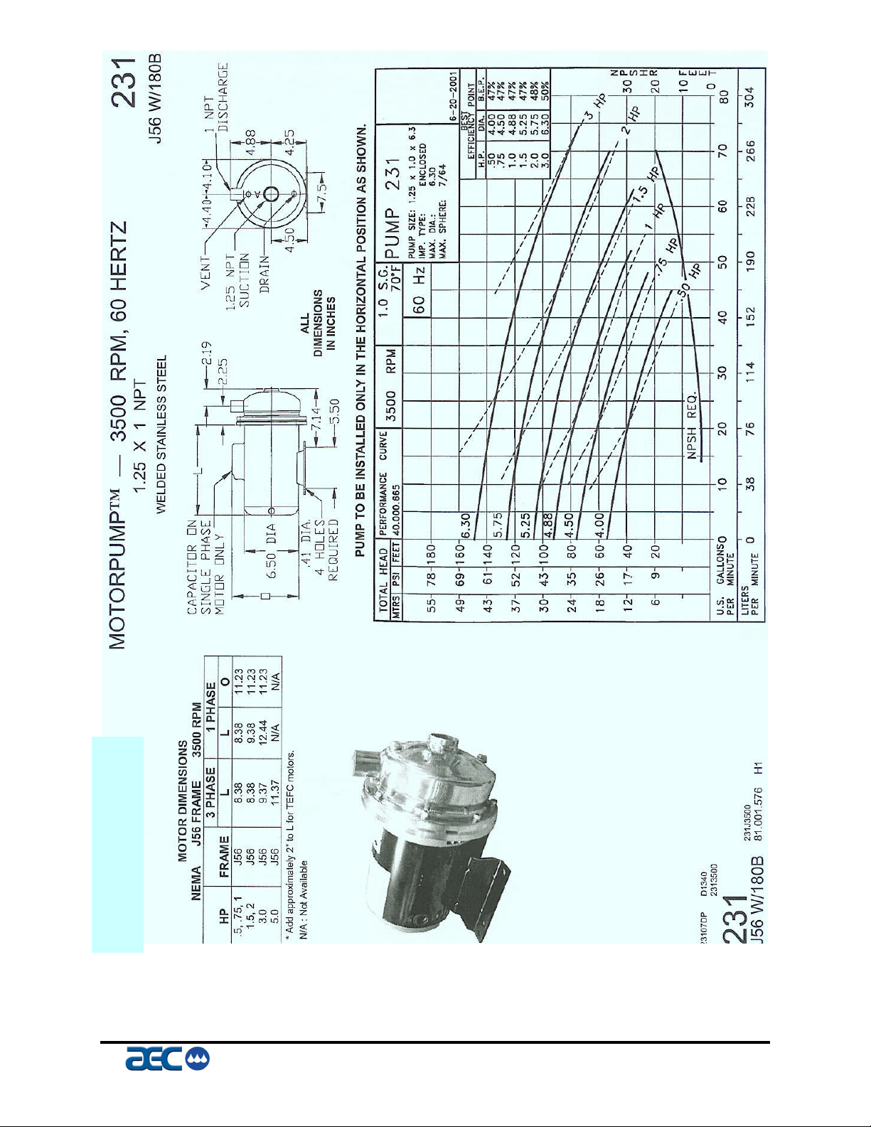
10-5 Pump Troubleshooting .................................................................. 71
I Index........................................................................ 77
FSS Series Fountain Solution Systems Page 5
IAE-600
Page 7

Charts and Figures
1
FSS Series 1.5 Hp Circulator 13
2
FSS Series 3.5 Hp Circulator 14
3
FSS Series 5 Hp Circulator 15
4
FSS-R Remote Condenser Assembly Models 16
5
FSS Series Return Pump Curve (3/8” & ½”) 26
6
FSS Series Return Pump Curve (3/4” & 1”) 27
7
Remote Condenser Piping Trap Locations 31
8
Remote Condenser Piping Trap Locations 32
9
Remote Condenser Piping Trap Locations 32
10
11
12
13
14
Refrigerant Line Sizing 32
Liquid Line Sizing 33
Discharge Line Sizing 34
FSR Chiller & Condenser Charge 34
Field Installed Piping Charge 34
Page 6 FSS Series Fountain Solution Systems
IAE-600
Page 8

1 General Information
1-1 Introduction
AEC, Inc. Fountain Solution Systems Series Circulators are
reliable, accurate, and easy to use press cooling units. They are
available in air-, water-, and remote air-cooled designs in a range
of sizes from 1.5 to 40 tons. All are self-contained, some units are
fully portable, and shipped ready-to-use (remote air-cooled chillers
require field installation by qualified technicians).
Standard range of operation is 50°F to 70°F (10°C to 21°C).
A properly installed, operated, and maintained FSS Series
circulator provides many years of reliable operation. To get the
most satisfaction from your new circulator, read and follow the
instructions in this manual.
1-2 Necessary Documents
The following documents are necessary for the operation,
installation, and maintenance of an AEC, Inc./FSS Series Fountain
Solution Systems. Additional copies are available from AEC, Inc.
Make sure that the appropriate personnel are familiar with
these documents:
• This manual.
• The electrical schematic and connection diagram mounted
inside the control enclosure.
• The operation and installation manuals for accessories and
options selected by the customer.
• The Customer Parts List included in the information packet.
FSS Series Fountain Solution Systems Page 7
IAE-600
Page 9

1-3 Models Covered
This manual provides operation, installation, and maintenance
instructions for AEC, Inc./FSS Series Fountain Solution Systems.
You’ll find model numbers on the serial tag. You should know the
model number, serial number, and operating voltage of your
circulator if you need to contact AEC, Inc.
FSS Series circulator models are designated by approximate
compressor horsepower (1½, 3½, 5, 7½, 10, etc.) and the cooling
method used—air-cooled are FSS-A, water-cooled are FSS-W, and
remote air-cooled units are FSS-R.
1-4 Standard Features
Mechanical Features
Compressor
Hermetic scroll compressors are used on 1.5 hp through 40 hp
models.
Evaporator
Stainless steel nickel brazed plate evaporators are used on all
models.
Air-Cooled Condenser (FSS-A)
Aluminum fin/copper tube with washable filters, on model FSS 1.5
package unit only.
Water-Cooled Condenser (FSS-W)
Three (3) hp to 7.5 hp (1.49 kW to 5.95 kW), tube-in-tube; all
come with cooling water regulating valves for chilled cooling
water or city water.
Remote Air-Cooled Condenser (FSS-R)
Eight (8) hp to 40 hp (3.73 to 29.83 kW) only; aluminum
fin/copper tube with optional low ambient control down to -20°F (29°C) via pressure-actuated fan staging and a variable-speed
primary fan.
Reservoir
A fifteen- (15) gallon stainless steel tank is used on the 2 hp model,
50-gallon stainless steel tank is used on the 3 hp, 5 hp and 7.5 hp
Page 8 FSS Series Fountain Solution Systems
IAE-600
Page 10

portable models, and a 35-gallon stainless steel tank is used on the
3 hp, 5 hp, and 7.5 hp stand alone models.
Piping
Process piping is non-ferrous stainless steel or polypropelene
piping for all models.
Pump
Non-overloading ODP motors, horizontally mounted stamped
stainless steel construction.
Other Mechanical Features
• Externally valved drain
• Low condensor water pressure switch
• Low process water flow switch - optional
• NEMA-rated ODP fan motor(s) (FSS-R air-cooled chillers)
• Stainless steel frame, painted cabinetry, on stand alone
models, 2½” (6.4 cm) swivel casters on 2 hp models, 4” (10
cm) swivel casters on 3 hp and 5 hp models.
Electrical Features
• Process water bypass for system protection only.
• To Process 2 ½” (63 mm) dual scale liquid-filled water
pressure gauge
• Fully insulated refrigeration piping
• Easy access to the mechanical cabinet
• Continuous Dual Filtration
• Digital Conductivity Readings 0 – 5000
mµs
• Fully accessible electrical control enclosure on 2 hp to 40 hp
models
• Single-point power and ground connection
• Non-fused (lockable) disconnect switch
• Branch circuit protection
• 230/3/60 and 460/3/60 volt
• 24v DC Control Voltage
• Consult factory for other applications
FSS Series Fountain Solution Systems Page 9
IAE-600
Page 11

Refrigeration Features
Controller Features
• R-22 refrigerant
• Hot gas bypass capacity control
• High and low refrigerant pressure cut-out switches
• Fan cycling switch on remote models
• High pressure spring actuated relief valve
• Multiple refrigeration access ports
• Compressor service valves
• Hot gas bypass and liquid line shut-off ball valves
• Filter-dryer
• Sight glass
• Balanced port thermal expansion valve
• Off-the-shelf, microprocessor-based, PID auto-tuning
controller with To Process and Set Point LED readout
• Microprocessor temperature switch with LCD display for
process water freeze protection with compressor cut-out
• Time delay for proof of water or pressure flow
• Off-delay timer to prevent short cycling of compressor
Other Features
• One (1) year warranty on compressor and labor
• Two (2) year warranty on parts
• Three (3) year limited warranty on controller
1-5 Available Options
FSS Series circulators are available with options that tailor the unit
to your requirements. Some must be factory installed and some can
be retrofitted in the field. Consult your sales representative for
more information.
Page 10 FSS Series Fountain Solution Systems
IAE-600
Page 12

Process Solution Return Filter
Also Available as Field Retrofit Kit
The Process Solution Return Filter option includes a free standing
Stainless Steel filter housing, 7” or 14” cartridges with a rating of
20 Microns (depending on filtration required; other sizes
available), with inlet & outlet pressure gauges, and manual bypass
for easy replacement of cartridges without shutting down the
process.
General Fault Indicator Audible Alarm
Also Available as Field Retrofit Kit
The General Fault Indicator Audible Alarm option includes an 85
dB @ 2 ft. (61 cm) audible alarm buzzer and silence button with
provisions for customer wiring indication interlock. The alarm
signals anytime that a fault is recognized during the operation of
the chiller.
FSS Series Fountain Solution Systems Page 11
IAE-600
Page 13

Compressor Hour Meter
Also Available as Field Retrofit Kit
The Compressor Hour Meter option includes a DIN-mount hour
meter that keeps track of the total time that the compressor runs.
Communications Options
External communications options for your unit include RS-232C
and RS-485 communications standards.
pH Indication
Digital Readout of Fountain Solution pH readings from 0 - 10
UL Labeled Electrical Subpanel
The UL Labeled Electrical Subpanel option provides for the
subpanel to be listed with Underwriters Laboratory, with ULrelated benefits and features.
PLC Controlled
The optional PLC unit controls all aspects of your Fountain
Circulator. Operator Interface has easy to access menus while
providing security for those areas not used by operators. Other
features include: providing a history when alarm is set off; trending
of your vital control points and communications with other press
equipment. Optional communications modem allows AEC service
technicians the capabilities of troubleshooting or system
diagnostics over the phone without any downtime.
Optional Pumps
Pump options are available for greater pressure and flow rates.
Page 12 FSS Series Fountain Solution Systems
IAE-600
Page 14
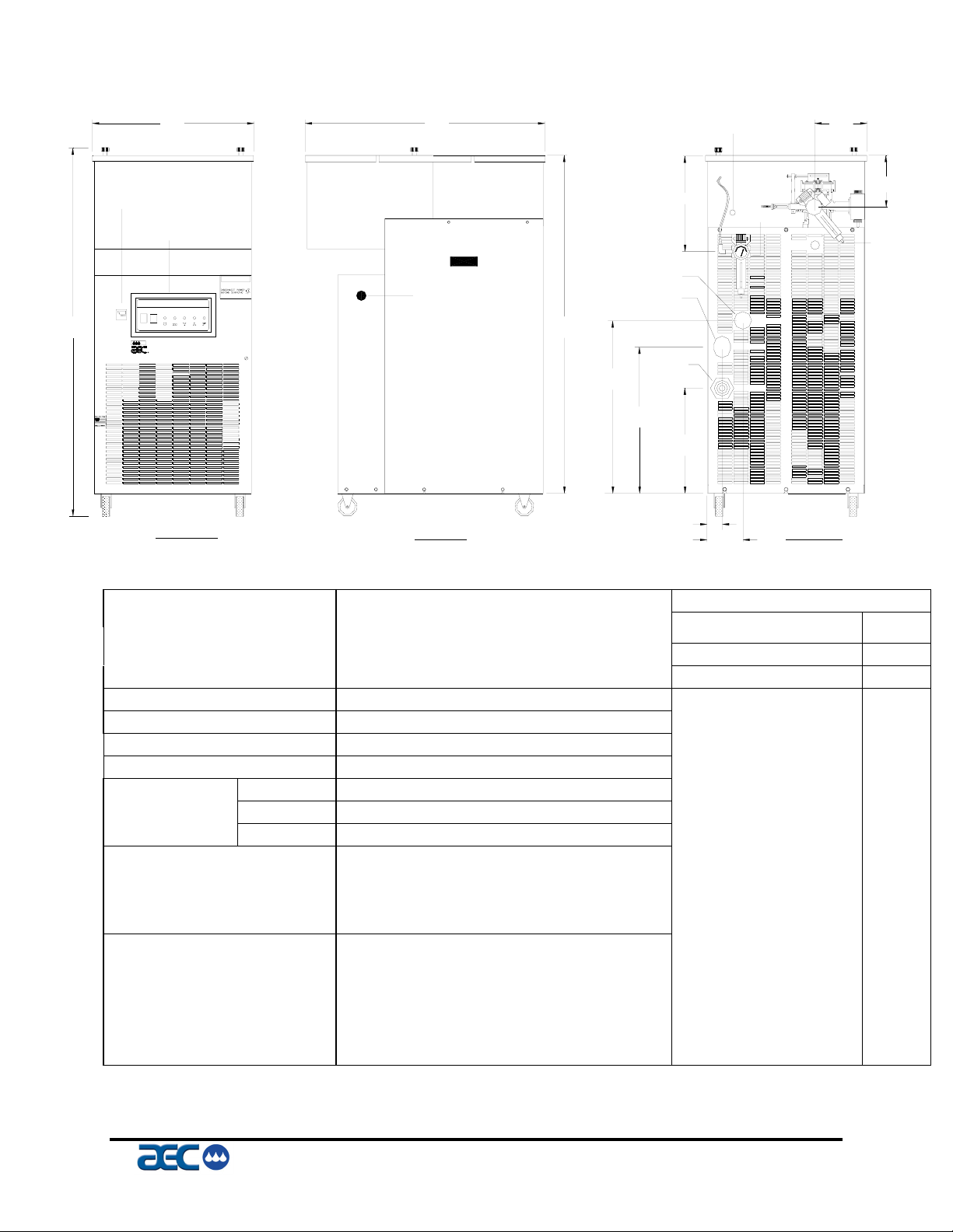
FSS Series 1.5 hp Circulator
20" 30"
Figure 1
OVER
FLOW
7"
TEMPERATURE
CONTROLLER
OPERATOR
PANEL
PFC PORTABLE FOUNTAIN CIRCULATOR 1.5
POWER
PUMP
HIGH
LOW
LOW
COMPRESSOR
HOT GAS
ON
ON
REFRIGERANT
TANK
REFRIGERANT
ON
BY−PASS
PRESSURE
LEVEL
PRESSURE
OFF
46"
OFF
A p p l i c a t i o n
E n g i n e e r i n g
FRONT VIEW
Portable Fountain Solution Control with Integral Air-Cooled Condenser
Model / Part Number
Voltage
Leaving Fountain Solution
Cooling Capacity c
Nominal Fountain Solution Flow
Nominal Fountain Solution Pressure
Condenser Air Flow
Temperature Display
Installation Site Elevation
Dimensions
Standard Connected Power
Shipping Weight
Operating Weight
Connections
Process
Water Make-up
Overflow
Drain
Etch/Additive
Air
c
Cooling capacity based on operation with 55°F leaving fountain solution temperature, 95°F ambient air, standard pump, 60 hertz
operation and operation sea level.
DANGER
Length
Width
Height
12"
7"
AIR IN
WATER IN
FROM PROCESS
POWER CABLE
ENTRANCE
TO PROCESS
43"
DRAIN
22"
18"
13"
SIDE VIEW BACK VIEW
2"
5"
PFC-1.5AG Nameplate Amps (460/3/60)
460/3/60
55ºF
Compressor and fan 2.6
1.5-tons [(18,000 Btu/hr) (4,536 K-cal/hr) (5.3 kW)] Standard 1/2-hp Pump 1.0
5 GPM Standard Total 3.6
18 PSI
1,225 CFM
Fahrenheit
Sea level
30 inches
20 inches
46 inches
3.6 amps
295 pounds
345 pounds
Size Type
½ - inch hose barb
½ - inch hose barb
½ - inch hose barb
½- inch hose barb
3/8– inch
3/8– inch
inch tube
inch tube
FSS Series Fountain Solution Systems Page 13
IAE-600
Page 15
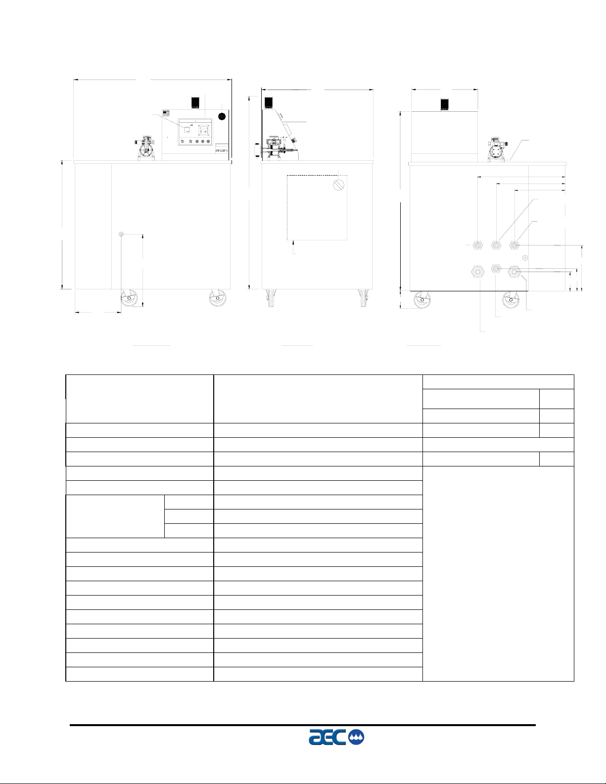
Figure 2
FSS Series 3.5 hp Circulator
39"
TEMPERATURE
CONTROLLER
DRAIN
14"
47"
22"
FRONT VIEW
CONDUCTIVITY
DISPLAY
E-STOP
PFC PORTABLE FOUNTAIN CIRCULATOR-5
CONDUCTIVITY
TEMPERATURE
CONTROL
SOLUTION
ADDITIVE
ETCH
CIRCULATOR
CIRCULATOR
OFF
SUPPLY PUMP
DRUM
TANK
DRUM
SYSTEM
ON
LOW LEVEL
LOW LEVEL
LOW LEVEL
OFF ON
DANGER
34"
63"
ALARM LIGHT
OPERATOR
PANEL
ELECTRICAL
ENCLOSURE
SIDE VIEW
DISCONNECT
53"
5.5"
BACK VIEW
emergency
stop
20"
WATER IN
METERING PUMP
26"
21"
OVER
FLOW
TO PROCESS
3/8" CHEM
CONNECTION
15"
CONDENSER
OUT
CONDENSER
IN
AIR IN
FROM PROCESS
14"
7"
6"
Portable Fountain Solution Control with Integral Water-Cooled Condenser
Model / Part Number
Voltage
Leaving Fountain Solution Temp.
Cooling Capacity c
Nominal Fountain Solution Flow
Nominal Fountain Solution Pressure
Condenser Water Flow
Temperature Display
Installation Site Elevation
Dimensions
Length
Width
Height
Standard Connected Power
Shipping Weight
Operating Weight
Process Connections
Condenser Connections
Water Make-up
Overflow
Internal Tank Drain
Etch/additive
Air Connections
c Cooling capacity based on operation with 50°F leaving fluid temperature, 95°F ambient air, standard pump, 60 hertz operation and
operation sea level.
PFC-3.5WG Nameplate Amps (460/3/60)
460/3/60
55ºF
Compressor 6.5
3.5-tons [(42,000 Btu/hr) (10,584 K-cal/hr) (12.3 kW)] Standard 2-hp Pump 3.4
7 GPM Standard Total 9.9
50 PSI
18 GPM 3 hp process pump 4.8
Fahrenheit
Sea level
34 inches
47 inches
59 inches
15 amps
pounds
pounds
1 inch hose barb
1 Inch hose barb
1 Inch hose barb
1 Inch hose barb
½ Inch hose barb
3/8 Inch tube
3/8 Inch tube
Page 14 FSS Series Fountain Solution Systems
IAE-600
Page 16
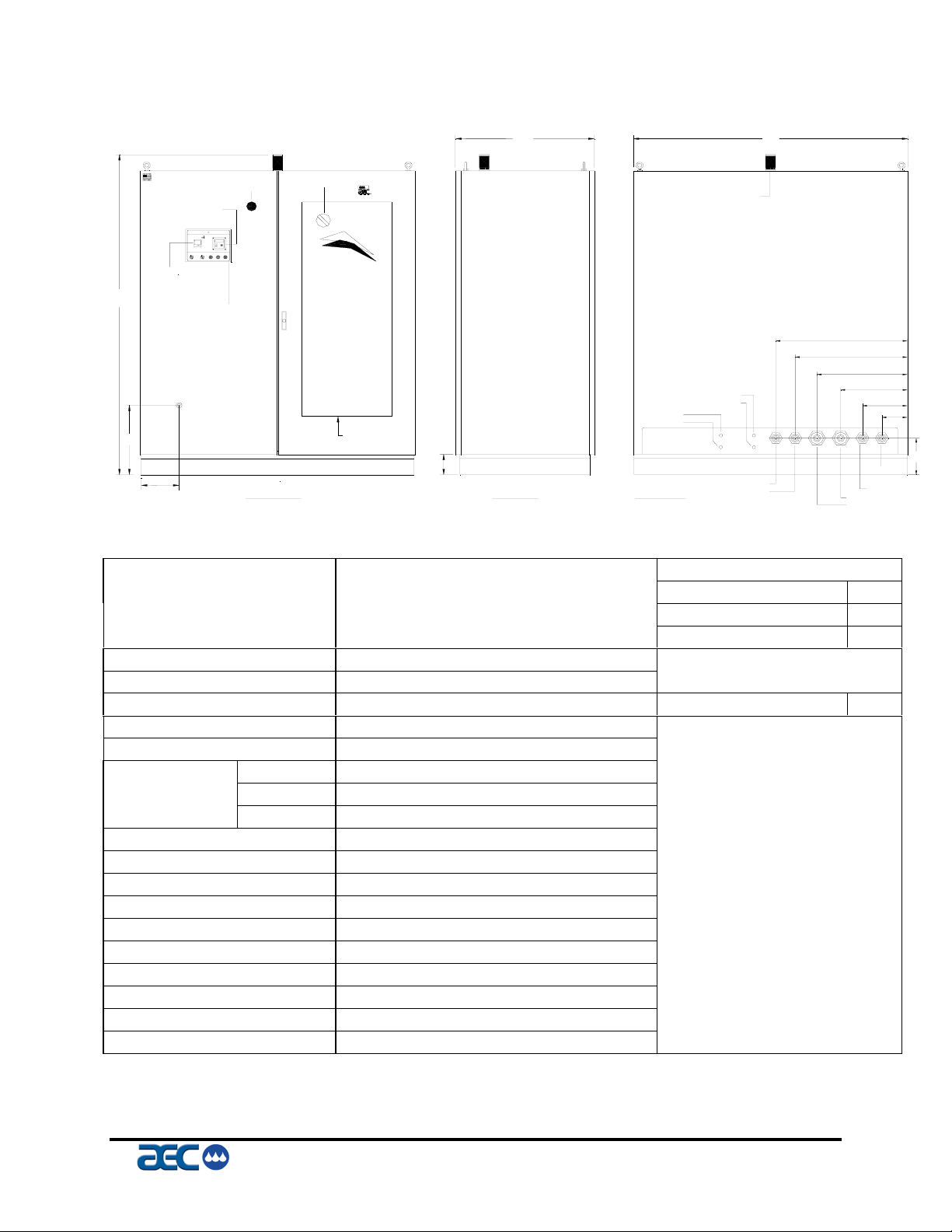
Figure 3
FSS Series 5 hp Circulator
TEMPERATURE
CONTROLLER
79"
17"
CONDUCTIVITY
DISPLAY
PFC PORTABLE FOUNTAIN CIRCULATOR-5
TEMPERATURE
CONTROL
SOLUTION
CIRCULATOR
CIRCULATOR
OFF
SUPPLY PUMP
TANK
SYSTEM
ONOFF LOW LEVEL
ON
OPERATOR
PANEL
DRAIN
9"
CONDUCTIVITY
ADDITIVE
ETCH
DRUMDRUM
LOW LEVEL LOW LEVEL
E-STOP
emergency
stop
FRONT VIEW
DISCONNECT
A p p l i c a t i o n
E n g i n e e r i n g
ELECTRICAL
ENCLOSURE
32"
ALARM LIGHT
AIR IN
AIR OUT
ETCH
ADDITIVE
5"
CONDENSER OUT
SIDE VIEW
BACK VIEW
CONDENSER IN
63"
30"
26"
21"
15"
OVER
FLOW
WATER IN
FROM PROCESS
TO PROCESS
Fountain Solution System with Integral Water-Cooled Condenser
Model / Part Number
Voltage
Leaving Fountain Solution Temp
Cooling Capacity c
Nominal Fountain Solution Flow
Nominal Fountain Solution Pressure
Condenser Water Flow
Temperature Display
Installation Site Elevation
Dimensions
Length
Width
Height
Standard Connected Power
Shipping Weight
Operating Weight
Process Connections
Condenser Connections
Water Make-up
Overflow
Internal Tank Drain
Etch/Additive Connections
Air Connections
c Cooling capacity based on operation with 55°F leaving fountain solution temperature, 85°F condenser water, standard pump, 60
hertz operation and operation sea level.
FSS-5WG Nameplate Amps (460/3/60)
460/3/60 Compressor 10
55ºF Standard 2 hp pump 3.4
5-tons [(60,000 Btu/hr) (15,120 K-cal/hr) (17.6 kW)] Standard Total 13.4
23 GPM
43 PSI
15 GPM at 85 ºF 3-hp process pump 4.8
Fahrenheit
Sea level
32 Inches
63 Inches
79 Inches
20 amps
pounds
pounds
1 inch hose barb
1 inch hose barb
1 inch hose barb
1 inch hose barb
½ inch hose barb
3/8 inch tube
3/8 inch tube
10"
6"
9"
FSS Series Fountain Solution Systems Page 15
IAE-600
Page 17
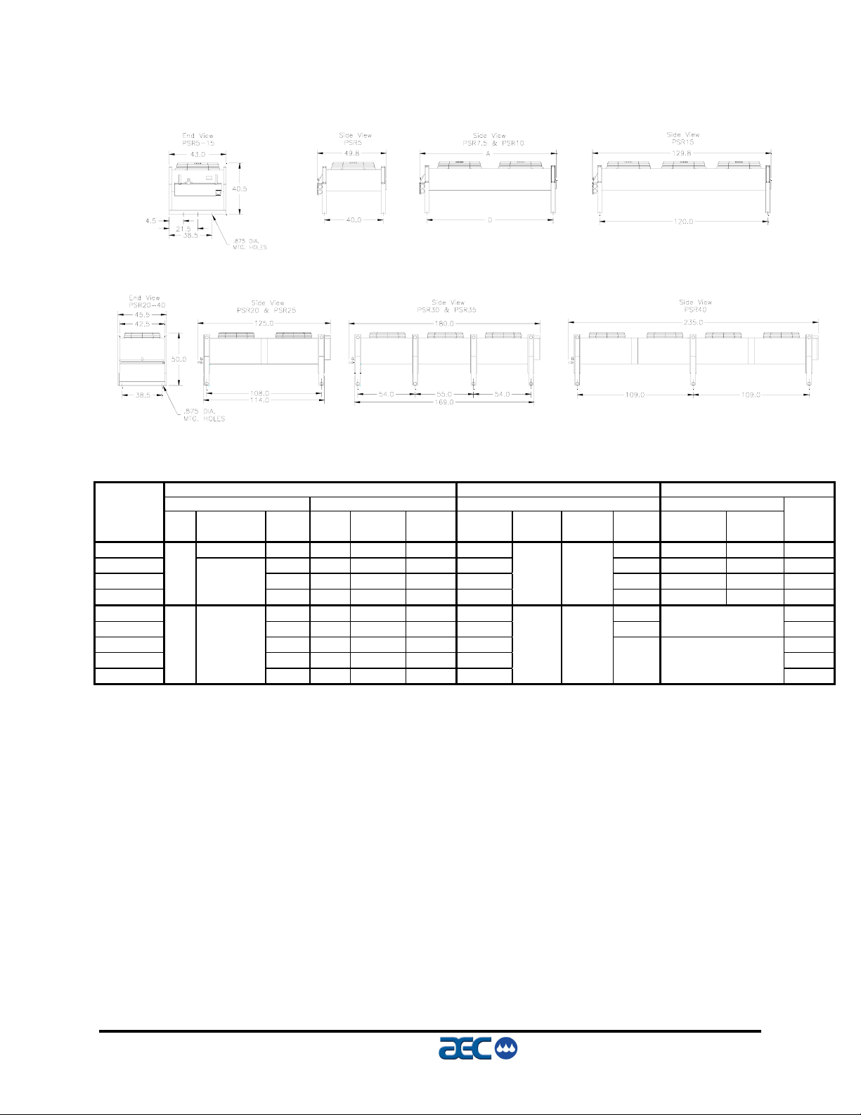
Figure 4
FSS-R Remote Condenser Assembly Models
To convert inches to cm, multiply dimension by 2.54.
Each Totals e f Overall Dimensions Connections Charge
Model Dia. Motor Amps Air flow Net wt. Length Width Height Mtg. Discharge Liquid R-22
Number in. hp c 460V Fans cfm h lbs. h ‘A’(in.) ‘B’(in.) ‘C’(in.) ‘D’(in.) ODS(in.) ODS(in.) lbs. g
FSS-R5 ¾ hp 1 ø 2.4 1 6,450 260 49.8 40.0 1⅛⅞3.6
FSS-R7.5 3.7 2 12,400 470 69.8 60.0 1⅛⅞3.6
FSS-R10 3.7 2 13,700 510 89.8 80.0 1⅜ 1⅛ 4.6
FSS-R15
FSS-R20 5.9 2 23,000 840 125.0 108.0 10.0
FSS-R25 5.9 2 21,900 860 125.0 108.0
FSS-R30 9.4 3 34,800 1,280 180.0 24.0
FSS-R35 9.4 3 32,900 1,300 180.0 24.0
FSS-R40
c ø represents electrical phase; all motors are 1,140 rpm. Multiply hp by 0.746 to convert to kW.
d All first fan motors (Header Side) are ¾ hp (0.56 kW) single phase variable speed.
e Multiply 460V amperages by 2.0 for 208-230V amperages.
f Multiply 460 V amperages by 0.8 for 575 V amperages.
g Refrigeration charge is for remote condenser only!
h To convert cfm to cmh, multiply by 1.699. To convert lbs. to Kg, multiply by 0.454.
26
⅓ hp 3 ø
30 1 ½ hp 3 ø
Fan(s) d e f Remote Condenser Refrigeration g
43.0 40.5
5.0 3 20,500 550 129.8
45.5 50.0
12.9 4 46,400 1,690 235.0
120.0 1⅝ 1⅛ 6.4
1⅝
i
2⅛
16.0
29.0
i See drawing above.
Page 16 FSS Series Fountain Solution Systems
IAE-600
Page 18
2 Shipping Information
2-1 Unpacking and Inspection
You should inspect your AEC, Inc./ Fountain Solution System
Series circulator for possible shipping damage. If the container and
packing materials are in re-usable condition, save them for
reshipment if necessary.
Thoroughly check the equipment for any damage that might have
occurred in transit. In case of breakage, damage, shortage, or
incorrect shipment refer to the following sections.
2-2 In the Event of Shipping Damages
Important!
According to the contract terms and conditions of the Carrier,
the responsibility of the Shipper ends at the time and place of shipment.
; Notify the transportation company’s local agent if you discover
damage.
; Hold the damaged goods and packing material for the
examining agent’s inspection. Do not return any goods to AEC,
Inc. before the transportation company inspection and
authorization.
; File a claim against the transportation company. Substantiate
the claim by referring to the agent’s report. A certified copy of
our invoice is available upon request. If the shipment was
prepaid, call us for a receipted transportation bill.
; Advise AEC, Inc. regarding your wish for assistance and to
obtain an RMA (return material authorization) number.
FSS Series Fountain Solution Systems Page 17
IAE-600
Page 19
2-3 If the Shipment is Not Complete
Check the packing list. You should have:
; AEC, Inc./ Fountain Solution System Circulator
; Bill of lading for equipment shipped
; Operation and Installation packet
; Electrical schematic and panel layout drawings
Re-inspect the container and packing material to see if you missed
any smaller items during unpacking. Determine that the item was
not inadvertently taken from the area before you checked in the
shipment. Notify AEC, Inc. immediately of the shortage.
2-4 If the Shipment is Not Correct
If the shipment is not what you ordered, contact the AEC, Inc.
shipping department immediately. For shipments in the United
States and Canada, call 1 (800) 233-4819; for all other countries,
call our international desk at 001 (630) 475-7491. Have the order
number and item number available.
Hold the items until you receive shipping instructions.
2-5 Returns
Do not return any damaged or incorrect items
until you receive shipping instructions from AEC, Inc.
Important!
Page 18 FSS Series Fountain Solution Systems
IAE-600
Page 20
2-6 Uncrating
FSS Series Portable Chiller Models 2 hp to 5 hp
FSS Series portable circulators are shipped mounted on a skid,
enclosed in a plastic wrapper, and contained in a cardboard box.
Remove the nails holding the box to the skid and lift the box off
carefully, avoiding staples in the 1’ x 4’ wood supports. Cut steel
banding.
Use a pry bar to remove the blocks securing the unit to the skid.
Insert forks between skid and portable chiller from the side until they
protrude beyond the opposite side of the unit. The forks must be
equidistant from the centerline of the unit and the unit must be
balanced on the forks.
Lift the unit off the skid with a fork truck. Lift slowly and only high
enough to clear the skid. Use a pry bar if necessary to carefully
remove the skid from the unit.
Lower slowly. The unit should land on its casters or rails and can then
be moved into position.
Temporary hardware has been installed to prevent side panels from
shifting in transit. Remove hardware.
Important!
Retain the crating material for reshipping the circulator in case hidden shipping
damage is found.
FSS Series Stand Alone Circulator Models 3 hp to 10 hp
FSS Series stand alone circulators are shipped mounted on a skid,
enclosed in a plastic wrapper, and open-crated on all four sides and
top.
1. Pry the crating away from the skid.
2. Repeat steps as noted above.
Important!
Never remove the unit from the front (electrical control end) or the rear (pipe
connection end) – DAMAGE MAY RESULT.
FSS Series Fountain Solution Systems Page 19
IAE-600
Page 21

- Notes-
Page 20 FSS Series Fountain Solution Systems
IAE-600
Page 22
3 Installation
3-1 Making Electrical Connections
Check serial tag voltage and amperage requirements and make sure
your electrical service conforms. Total running amps for FSS
Series circulators are also found in the specification tables in
Figures 1 through 4 on Pages 14 through 17.
Bring properly sized power leads and ground from a fused disconnect (installed by your electrician) to the unit. Use dual-element
fuses in the disconnect switch, sized according to National
Electrical Code recommendations. Note the outline drawings for
egress into the cabinet. Make sure all electrical connections are
tight.
! WARNING
1. Make sure that electrical connections
comply with all applicable electrical codes.
2. Ground the unit in accordance with NEC
Article 250.
3. Operating voltage must be within plus or
minus ten percent (±10%) of the nameplate
rating.
4. Phase imbalance must be below 10%.
FSS Series Fountain Solution Systems Page 21
IAE-600
Page 23

3-2 Making Process Connections
All Models
All FSS Series circulators have a bulkhead plate with the following
connections in the back:
• The system overflow connection, labeled Overflow, is the 1”
outlet for the system reservoir overflow. This should be
connected per local codes for a chemical drain and not to a
city drain.
• The city water “in” connection, labeled Water In, is the 1”
inlet leading from the customers city water make-up.
• The press process supply connection, labeled To Process, is
the 1” (1.5”) outlet for the supply solution to the press.
• The press process return connection, labeled From Process,
is the 1” (1.5”) inlet from the return pump/return tank.
• The condenser water “in” connection, labeled CHW In, is
the 1” connection from customers central chilling system
supply or from customer city water supply.
• The condenser water “out” connections, labeled CHW Out,
is the 1” connection to the customers central chilling water
return or to the customers city water return.
• The air supply connection for the systems return pump
controls, labeled Air In, is the ½” polytube connection from
the customers central air supply.
• The air supply connection for the return pump, labeled Air
Out, is the ½” polytube connection to the systems return
pump air inlet.
• The Etch Chemical connection, labeled “ETCH”, is the 3/8”
polytube connection from the chemical wand located in the
customers drum or tote.
• The Additive Chemical connection, labeled “ADDITIVE”,
is the 3/8” polytube connection from the chemcial wand
located in the customers drum or tote.
Page 22 FSS Series Fountain Solution Systems
IAE-600
Page 24
FSS Series Fountain Solution Systems Page 23
IAE-600
Page 25
Page 24 FSS Series Fountain Solution Systems
IAE-600
Page 26

FSS Series Fountain Solution Systems Page 25
IAE-600
Page 27

Figure 5
FSS Series Return Pump Curve
3/8”
1/2”
Page 26 FSS Series Fountain Solution Systems
IAE-600
Page 28

Figure 6
FSS Series Return Pump Curve
3/4”
•
1”
FSS Series Fountain Solution Systems Page 27
IAE-600
Page 29

3-3 Water Treatment Considerations
Water treatment is an integral part of the system. In some
locations, water may cause large deposits of scale, erosion, algae,
and/or corrosion.
The use of a poor quality water may result in inefficient operation,
heat exchanger damage, and pump seal damage. Consult a
qualified water treatment specialist to determine whether treatment
is needed.
AEC, Inc. offers a complete line of water treatment equipment.
Contact your AEC, Inc. sales representative for water testing and
treatment options.
3-4 Water-Cooled Chiller Condenser Connections
FSS Series Water-Cooled Chillers
FSS-W Series water-cooled circulators can use city water as a
cooling medium or make-up. Make sure that all external piping
and connections supplying and discharging water to and from the
condenser are full size.
You’ll make two (2) connections to the water cooled condenser:
• The condenser water supply, labeled
IN
, is located at the rear of the unit, and is the inlet for city
water or central chill water system.
Make sure that water is supplied at a maximum temperature
of 85°F (29°C) and a minimum pressure of 25 psi
(172.4 kPa/1.7 bars).
CONDENSER WATER
! CAUTION
The water-regulating valve is set at the factory.
Only a qualified refrigeration technician should adjust it!
Normal R-22 refrigerant condensing pressure is 210 psi
(1,447.9 kPa/14.5 bars), with 85°F (27°C) water at 25-psi
(172.4 kPa/1.7 bars) entering condenser water pressure.
• Condenser water return, labeled
OUT
, is located at the rear of the unit, and is the outlet for
water after it has passed through the condenser.
CONDENSER WATER
Page 28 FSS Series Fountain Solution Systems
IAE-600
Page 30

It is connected to the return of a central chill water system or
to a sewer or other approved discharge receiver. A water
regulating valve is a standard feature in the condenser water
return line.
3-5 Air-Cooled Condenser Chiller Air Supply
FSS-A Series Air-Cooled Chillers
FSS-A Series air-cooled circulators use the surrounding air to cool
the condenser. Install the circulator in an area where there is free
passage of air for condensing and provisions for removal of heated
air from the area.
Do not locate FSS Air Series circulator in locations where steam,
hot air, or fume exhausts can be drawn into the chiller.
! CAUTION
Clean air-cooled condensers and filters frequently. Failure to do so results in
reduced capacity, increased operating costs, and possible failure of the
equipment. See Section 9 on Page 67 for cleaning instructions.
Normal maximum R-22 refrigerant condensing pressure with 95°F
(35°C) air entering the condenser is 260 psi (1,792.7 kPa/17.9 bars).
3-6 Condensing Air Temperature
FSS Series circulators are designed to operate at a minimum condenser entering air temperature of approximately 60°F (15.5°C).
Operation of the equipment at a lower condenser entering air
temperature can cause the unit to lose capacity. For entering air
temperatures below 60°F, an optional fan motor speed control is
available, please consult factory.
AEC, Inc. recommends that you maintain ambient temperature at
60°F (15.5°C) or above.
FSS Series Fountain Solution Systems Page 29
IAE-600
Page 31

3-7 FSS-R Series with Remote Condenser
FSS-R Series circulators are shipped with a nitrogen holding
charge and a full charge of oil (excluding the amount needed for
field piping). The FSS-R condenser is shipped with a dry air
charge. Verify that the holding charge has not been lost prior to
installation. If there is no pressure, leak test the unit and repair
before installing the interconnecting refrigerant piping. Read this
complete section before installation.
Important!
Piping should be type ‘L’ or type ‘K’ refrigerant grade copper tubing only.
Proper sizing and installation has a significant effect on system performance,
reliability, and safety!
Interconnecting Refrigerant Piping
The circulator and condenser refrigerant lines are terminated with a
cap and brazed closed. Do not use a saw to remove the end caps
since this will allow copper chips to contaminate the system. Use
a tube cutter to remove caps. A certified refrigeration contractor
need only to install the interconnecting refrigerant piping between
the FSS-R circulator and the outdoor air-cooled condenser. For
safe reliable operation, this piping must be properly sized, Type
‘L’ or Type ‘K’ high temperature brazed, refrigerant grade tubing.
Following all codes, install a customer supplied, 400 psi approved,
refrigerant relief valve in the discharge line at the condenser.
When brazing copper joints, flow dry nitrogen through the system.
This will prevent carbon/scale formation that causes
contamination. Isolate the refrigerant lines from the building,
preventing transfer of line vibration to the structure. Do not secure
the lines rigidly.
Leak check and evacuate the system down to 400 microns. A
decay of 50 microns after one hour is acceptable.
! CAUTION
To prevent injury or death due to explosion and/or inhalation of phosgene gas,
purge system thoroughly while brazing refrigerant piping connections. Use a
pressure regulator in the line between the unit and the high-pressure nitrogen
cylinder to avoid over-pressurization and possible explosion.
Page 30 FSS Series Fountain Solution Systems
IAE-600
Page 32

System Configuration
The system can be configured in any of the arrangements shown in
Figures 7, 8 and 9. The configuration and distance between them
effects pipe size, refrigerant charge, oil return, and oil charge.
Therefore, there are limitations that must be adhered to for reliable
and optimal operation.
The limitations are as follows:
1. Leaving water temperature effects discharge line size,
be sure to inform the installing contractor of the leaving
water temperature range that the chiller will be
operating.
2. The total distance between the FSS-R Series circulator
and condenser must not exceed 200 feet or 300
equivalent pipe feet.
3. Liquid line risers must not exceed 15 feet from the base
of the air-cooled condenser (See figure 20).
4. Discharge line risers cannot exceed an elevation
difference greater than 100 feet without a 2% efficiency
decrease.
5. Refer to Figures 7, 8, and 9 for the location of traps.
6. Refrigeration lines must not be crossed. (i.e. chiller
liquid lines are to be piped to condenser liquid lines etc.)
7. Discharge lines should pitch downward, in the direction
of flow, at a rate of ½” per 10 feet of horizontal run. It
should be sized based upon velocity needed for
sufficient oil return.
Figure 7
LIQUID LINE
DISCHARGE LINE
TRAP
(Figure 7 – Remote Condenser Piping Trap Locations)
Liquid line riser should not exceed 15 feet from base of air-cooled condenser.
FSS Series Fountain Solution Systems Page 31
IAE-600
Page 33

LIQUID LINE
LIQUID LINE
Figure 8
INVERTED TRAP
DISCHARGE LINE
TRAP
Figure 9
INVERTED TRAP
DISCHARGE LINE
(Figures 8 & 9 – Remote Condenser Piping Trap Locations)
Sizing Refrigerant Lines
To determine field installed liquid and discharge line sizes, it is
first necessary to establish the equivalent length of pipe for each
line, valves, and elbows. Chiller capacity and leaving water
temperature range is also required. Figure 10 states the equivalent
length in feet, for refrigerant valves and fittings.
Example: If the actual length of horizontal piping for an FSSR-5 is
60 feet, the vertical piping is 35 feet, and (4) elbows (Figure 10)
are 6.4 feet. 60 + 35 + 6.4 = 101.4 equivalent feet, therefore the
liquid line piping size (Figure 24) would be 5/8”.
Line Size
Inches OD
1/2” 43 15 1.4 0.9
5/8” 55 18 1.6 1.0
7/8” 69 24 2.0 1.4
1 1/8” 87 29 2.7 1.9
1 3/8” 102 33 3.2 2.2
1 5/8’ 115 34 3.8 2.6
2 1/8” 141 39 5.2 3.4
2 5/8” 159 44 6.5 4.2
Globe Valve
Equivalent Ft
Figure 10
Refrigerant Line Sizing
Angle Valve
Equivalent Ft
Short Radius Elbow
Equivalent Ft
Long Radius Elbow
Equivalent Ft
Page 32 FSS Series Fountain Solution Systems
IAE-600
Page 34

Liquid Line Sizing
Discharge Line Sizing
The liquid line should be sized as small as possible, while
maintaining acceptable pressure drop, to minimize the refrigerant
charge. The total length between components must not exceed 200
actual feet or 300 equivalent feet. See Figure 11 for sizing.
Liquid risers should not exceed 15 feet.
Horizontal runs do not require a pitch. Insulation is not required
unless the line is installed in a high ambient area i.e. boiler room.
Install a liquid line charging valve to facilitate refrigerant charging.
Refer to Figures 13 and 14 for charge determination.
For horizontal runs, the discharge line should be pitched
downward, in the direction of flow, at a rate of ½ inch for every 10
feet. This will allow oil to flow towards the condenser.
Discharge line sizing is based on the velocity required for
sufficient oil return back to the compressor. Discharge line sizing
is shown in Figure 12.
Figure 11
Liquid Line Sizing
30 – 65°F Leaving Water Temperature
Liquid Line Size (O.D.”)
Eqiv. FT FSS-R-5 FSS-R-7.5 FSS-R-10 FSS-R-15 FSS-R-20 FSS-R-25 FSS-R-30 FSS-R-35 FSS-R-40
25 5/8 7/8 7/8 7/8 1 1/8 1 1/8
50 5/8 7/8 7/8 7/8 1 1/8 1 1/8
75 5/8 7/8 7/8 7/8 1 1/8 1 1/8
100 5/8 7/8 7/8 7/8 1 1/8 1 1/8
125 7/8 7/8 7/8 1 1/8 1 1/8 1 1/8
150 7/8 7/8 1 1/8 1 1/8 1 1/8 1 1/8
175 7/8 7/8 1 1/8 1 1/8 1 1/8 1 1/8
200 7/8 7/8 1 1/8 1 1/8 1 1/8 1 1/8
225 7/8 1 1/8 1 1/8 1 1/8 1 1/8 1 3/8
250 7/8 1 1/8 1 1/8 1 1/8 1 1/8 1 3/8
275 7/8 1 1/8 1 1/8 1 1/8 1 1/8 1 3/8
300
5/8 5/8
7/8
7/8
1 1/8 1 1/8 1 1/8 1 3/8 1 3/8
FSS Series Fountain Solution Systems Page 33
IAE-600
Page 35

Figure 12
Discharge Line Sizing
30 – 65°F Leaving Water Temperature
Discharge Line Size (O.D.”)
Eqiv. FT FSS-R-5 FSS-R-7.5 FSS-R-10 FSS-R-15 FSS-R-20 FSS-R-25 FSS-R-30 FSS-R-35 FSS-R-40
25 7/8 1 1/8 1 3/8 1 3/8 1 5/8 1 5/8 1 5/8
50 7/8 1 1/8 1 3/8 1 3/8 1 5/8 1 5/8 1 5/8
75 7/8 1 1/8 1 3/8 1 3/8 1 5/8 1 5/8 1 5/8
100 7/8 1 1/8 1 3/8 1 3/8 1 5/8 1 5/8 1 5/8
125 7/8 1 1/8 1 3/8 1 3/8 1 5/8 1 5/8 2 1/8
150 7/8 1 1/8 1 3/8 1 5/8 1 5/8 2 1/8 2 1/8
175 1 1/8 1 1/8 1 3/8 1 5/8 1 5/8 2 1/8 2 1/8
200 1 1/8 1 3/8 1 3/8 1 5/8 1 5/8 2 1/8 2 1/8
225 1 1/8 1 3/8 1 5/8 1 5/8 2 1/8 2 1/8 2 1/8
250 1 1/8 1 3/8 1 5/8 1 5/8 2 1/8 2 1/8 2 1/8
275 1 1/8 1 3/8 1 5/8 1 5/8 2 1/8 2 1/8 2 1/8
300 1 1/8
1 1/8
2 1/8
1 3/8 1 5/8 1 5/8 2 1/8 2 1/8 2 1/8
Refrigerant Charge Determination
The approximate amount of refrigerant charge required by the
system varies based upon the total length of the refrigerant lines
and the size of the chiller. First refer to Figure 13 for the amount of
charge based upon the model number of the chiller. Then add that
to Figure 14, discharge and liquid line refrigerant charges, based
upon line size and installed length of each. The final operating
charge must be verified by running the system and checking the
liquid line sight glass.
Figure 13 Figure 14
FSR Chiller + Condenser Charge
Chiller
Model
FSS-R5 5.9 1/2”
FSS-R7.5 6.1 5/8”
FSS-R10 10.8 7/8” 1.6 24.0
FSS-R15 12.6 1 1/8” 2.7 40.9
FSS-R20 21.2 1 3/8” 4.0 62.2
FSS-R25 24.2 1 5/8’ 5.7 88.1
FSS-R30 40.2 2 1/8” 10.0 153.0
FSS-R35 41.2 2 5/8” 15.0 236.0
FSS-R40 50.2
Lbs. of
Oil Charge Determination
The FSS-R Series circulators are factory charged with the amount
of oil required without field-installed piping. Additional oil
required is dependent upon the amount of additional refrigerant
added.
R-22
Field Installed Piping Charge
Pipe O.D.
Inches
c Based on 100 feet of pipe, 100 ºF Liquid, 100 ºF Discharge
Discharge
Line
c R-22(Lbs.)
˘
˘
Liquid Line
c R-22(Lbs.)
7.2
11.5
Page 34 FSS Series Fountain Solution Systems
IAE-600
Page 36

Calculate the amount of additional oil required by using the
following formula:
Lbs. of R-22 added
Pints of oil (Sunisco 3GS) = for field installed piping
100
3-8 Checking Motor Direction
All FSS circulators have their motor rotation(s) properly phased at
the factory. If compressors, pumps, or fans are running in reverse
rotation:
• Disconnect and lock out power at the source.
• Reverse any two power leads into the chiller disconnect
switch to change motor direction (all motors have been
phased in one direction at the factory).
Important!
Do not switch leads at the motors, motor starters, or contactors.
Three-Phase Compressors
Scroll compressors are directionally-dependent and compress in
one rotational direction.
Reversing rotation direction results in an elevated sound level over
the correct rotation; you’ll also observe substantially-reduced
current draw as compared with tabulated values.
Water Pumps
Correct pump rotation is indicated by a positive pressure of 20 to
40 psi (137.9 to 275.8 kPa/1.38 to 2.76 bars) on the pump pressure
gauge. Pump rotation should be clockwise when viewed from the
motor end.
Do not run pump dry, doing so will result in seal damage.
For pump performance, check the appropriate pump curve in
Figures 5 and 6 on Pages 27 and 28.
Important!
FSS Series Fountain Solution Systems Page 35
IAE-600
Page 37

The following table lists available glycol products available from
AEC, Inc.
Part no. Description Part no. Description
A0541358 Ethylene glycol, 5 gallons (18.9 liters) A0542990 Propylene glycol, 5 gallons (18.9 liters)
A0539637 Ethylene glycol, 55 gallons (208.2 liters) A0542991 Propylene glycol, 55 gallons (208.2 liters)
Installation Note: In applications where the process or process piping is above the
reservoir, take steps to prevent over pressurization of the reservoir.
This condition can occur on system shutdown when the water in
the system drains into the reservoir. To prevent this, a vacuum
breaker is installed at the high point of the
FROM PROCESS lines.
TO PROCESS and
Page 36 FSS Series Fountain Solution Systems
IAE-600
Page 38

4 Sequence of Operation
4-1 Solution Circuit
Cooling water To Process and From Process connections are
made at the hose barbs provided outside the unit. Warm solution
(water and chemical mixture) returns from the process and goes
into the reservoir tank. The coolant is then pumped through the
evaporator where it is cooled. The coolant flows to the process and
returns to repeat the cycle.
A process water bypass located between the supply line and
reservoir tank allows minimal flow through the unit during
intermittent fluctuating flow conditions. It is not intended to
provide continuous full bypass flow.
This minimal flow allows the temperature sensor to signal the
controller to shut down the compressor because of the drop in
process water temperature. Typically the flow switch shuts down
the chiller in this low flow condition.
4-2 Refrigeration Circuit
FSS Series circulators are available with air-, water-, or remote aircooled refrigerant condensing. The refrigeration cycles differ only
in the way the compressed gas is condensed to a liquid.
Liquid refrigerant from the condenser heat exchanger flowing in
the liquid line passes through a shutoff valve into a filter/dryer that
removes moisture and other contaminants. A refrigerant sight glass
is provided. The refrigerant then passes through the thermal
expansion valve which allows the refrigerant to expand (boil off),
and cool the fluid inside of the evaporator. The refrigerant gas
flows through the suction line back into the compressor.
FSS Series Fountain Solution Systems Page 37
IAE-600
Page 39

The refrigerant is compressed in the compressor and flows through
the discharge line as a gas to the condenser. There it gives up its
heat as it condenses to a liquid in the condenser.
A hot gas bypass valve is used to control cooling capacity during
intermittent or partial load conditions. This feature contributes
substantially to chiller longevity by eliminating excessive cycling
of the compressor and providing close temperature control.
Note the piping schematics on the following pages.
4-3 Low Thermostat Control
The Low thermostat is a cutout device that protects the chiller
system by shutting down the compressor if the chilled process
solution temperature approaches the particular mixture’s freezing
point. The chilled process water pump will continue to run.
The Low thermostat cutout temperature is set at the factory to
42°F (5.5°C). This is correct for a supply water temperature of
50°F (10°C), the rated capacity operating temperature.
! CAUTION
Protect the system from freezing with glycol that is
20°F (11°C) below the leaving water temperature set point. Because condensation
may form inside the pump tank and dilute the mixture, the freezing point should
be verified periodically.
Set High/Low thermostat cut-out temperature to 8°F (4.4°C) below the set point
leaving water temperature.
Your AEC, Inc. product warranty does not cover system freeze-ups!
Page 38 FSS Series Fountain Solution Systems
IAE-600
Page 40

4-4 Crankcase Heater
FSS-R Series models with remote condensers have a crankcase
heater. It is wired through the control transformer that operates
continuously whenever power is applied to the chiller.
! CAUTION
Energize the crankcase heater for at least 24 hours before initial startup
to drive dissolved refrigerant from compressor oil.
Failure to do so will damage the compressor!
4-5 High Pressure Cutout
This electro-mechanical cut-out device opens the compressor
control circuit if the refrigeration system compressor discharge
pressure exceeds 375 psi (2,413.25 kPa/24.1 bars) for an air-
cooled chiller and 290 psi (2,413.25 kPa/24.1 bars) for a watercooled chiller.
Important!
The high-pressure cutout is a manual reset device typically mounted on the
compressor discharge line inside the mechanical cabinet.
Call a refrigeration service technician to analyze the problem!
4-6 Low Pressure Cutout
This electro-mechanical cut-out device opens the compressor
control circuit if the refrigeration system compressor suction
pressure drops below 15 psi (220.6 kPa/2.2 bars). It automatically
resets when refrigerant suction pressure reaches 30 psi (344.8
kPa/3.4 bars).
Important!
The low pressure cutout is an automatic reset device typically mounted
on the compressor suction line inside the mechanical cabinet.
Call a refrigeration service technician to analyze the problem!
FSS Series Fountain Solution Systems Page 39
IAE-600
Page 41

4-7 Fan Cycling Switch
FSS Series Air-Cooled Models Only
FSS-A-5 and FSS-A-7.5 Models
These models have one fan. The fan cycling switch turns on the
fan when the discharge pressure in the condenser reaches 300 psi
(1,896.1 kPa/18.9 bars) and turns it off when the pressure drops
below 190 psi (1,379.0 kPa/13.8 bars).
FSS-A10 to FSS-A30 Models
These models have two fans. One fan runs continuously every time
the compressor operates. The second fan cycles based on the
parameters listed in the above section.
The fan cycling switch turns on the second fan when the condenser
pressure reaches 275 psi (1,896.1 kPa/18.9 bars) and turns it off
when the pressure drops below 200 psi (1,379.0 kPa/13.8 bars).
4-8 Pressure Switch
The pressure switch cut-out device, mounted in the process piping,
shuts down the chiller if it senses that the water pressure through
the evaporator has dropped below an acceptable level. The
pressure switch opens the control circuit, and shuts off the
chiller.
4-9 Flow Switch
The flow switch cut-out device, mounted in the process piping,
shuts down the chiller if it senses that the water flow rate through
the evaporator has dropped below an acceptable level. The flow
switch opens the control circuit shutting down the pump(s),
and the chiller shuts off.
4-10 Air Pressure Switch
The pressure switch cutout device, mounted in the air supply shuts
down the unit if it senses that the customer supplied air pressure
has dropped below the acceptable level. The pressure switch
opens the control circuit, shuts down the pump(s), and shuts
off the chiller.
Page 40 FSS Series Fountain Solution Systems
IAE-600
Page 42

- Notes -
FSS Series Fountain Solution Systems Page 41
IAE-600
Page 43

5 Setup Procedures
5-1 Conductivity Meter
GLI PRO-SERIES
1) Press the menu key.
2) Scroll down to configure and press enter.
3) Scroll down to set C (Celsius) or F (Farenheight) and press
enter.
4) Scroll up to change C (Celsius) to F (Farenheight) and press
enter.
5) Scroll down to sensor and press enter.
6) Scroll down to display format and press enter.
7) The screen should read display format.
8) Press the arrow up or down until screen reads <20.00 mS/CM>
and press enter.
9) Scroll down to temp element and press enter.
10) Scroll down to Set “T” factor? and press enter.
11) Look at the label on the sensor to get the resistance value. (eg:
T=1000.5)
12) Enter the value found on the sensor and press enter.
13) Scroll down to exit then press enter. (This will take you back
to the sensor screen)
14) Scroll down to exit again and press enter. (This will take you
back to the configure screen)
15) Scroll down to set output and press enter.
16) Scroll down to 4 mA value and press enter.
17) Change to 0.00 mS/CM and press enter.
18) Scroll down to 20.00 mA and press enter.
19) Set the 20 mA value to 5.00 mS/CM and press enter.
20) Scroll down to exit then press enter. (This will take you back
to the configure screen)
21) Scroll down to exit and press enter. (This will take you back
to the main menu screen)
22) Scroll down to calibrate then press enter.
23) Sensor should appear then press enter.
24) Scroll down to zero then press enter.
Page 42 FSS Series Fountain Solution Systems
IAE-600
Page 44

25) The display will read “Zero In Dry Air?”, press enter.
(screen will read, PLEASE WAIT)
26) Confirm Cal OK? will appear, press enter.
27) Confirm Active? will appear, press enter. (this will take you
back to the main operator screen)
28) Press the menu key.
29) Scroll to calibrate and press enter.
30) Scroll to sensor and press enter.
31) Scroll to cond cal and press enter.
32) The screen will read ref temp, it should be set at 25.0 C and
press enter.
33) “Set slope” will appear, it should be set at 2.00% C, then press
enter.
34) “Cond cal sample ready?” should appear, press enter.
35) “0.00mS/CM reading stable” should appear.
36) Put the sensor in a solution of 5000 mS and wait until the
reading stabilizes then press enter.
36A) Obtain a bottle of 5000 mS / CM conductivity solution
and determine its exact value using laboratory analysis or
a recently calibrated
portable meter.
37) “Cond cal?” should appear, if the reading is correct, press
enter. If not, use arrow keys to adjust the displayed value to
exactly match the known value of the process sample.
38) “Cond cal confirm, cal ok?” will appear, press enter.
39) Conductivity reading should be at the top of the screen. The
bottom message should read “Confirm active”, press enter.
(this will return you to the main operating screen)
40) Put a multi-meter in series with the +24 vDC wire.
41) Press the menu key.
42) Scroll down to calibrate and press enter.
43) Scroll down to cal output and press enter.
44) Scroll down to cal output 4 mA and press enter.
45) Change the value up or down until the multi-meter reads 4.00
mA, then press enter.
46) Scroll down to cal output 20 mA and press enter.
47) Change the value up or down until the multi-meter reads 20.00
mA, then press enter.
48) Scroll down to exit, then press enter to get back to the cal
output screen.
49) Scroll down to exit then press enter to go back to the main
menu.
FSS Series Fountain Solution Systems Page 43
IAE-600
Page 45

50) Scroll down to exit then press enter to go back to main
operator screen.
5-2 pH TRANSMITTER
GLI PRO-SERIES
1) Press the menu key.
2) Scroll down to the test/maintenance screen and press enter.
3) Scroll down to reset configuration and press enter.
4) The screen will read reset configure, are you sure? Press the
enter key. (The screen will read reset configure done, press
enter)
5) Scroll down to reset calibrate and press enter.
6) The screen will read reset calibrate, are you sure? Press the
enter key. (The screen will read reset calibrate done, press
enter.
7) Scroll down to exit and press enter to return to the test
maintenance screen.
8) Scroll up to configure and press enter.
9) Scroll down to C or F and press enter.
10) Change from Celsius to Faherenheit and press enter.
11) Scroll up to set output and press enter.
12) Scroll down to the 4 mA value and press enter.
13) Set the 4 mA value at 0.00 pH and press enter.
14) Scroll down to 20.00 mA and press enter.
15) Set the 20 mA value at 14.00 pH and press enter.
16) Scroll down to exit to get back to the set output screen.
17) Scroll down to exit and press enter to get back to the main
menu.
18) Scroll to configure and press enter.
19) Scroll to sensor and press enter.
20) Scroll down to select sensor and press enter.
21) Arrow up until diff pH appears and press enter to return to the
select sensor screen.
22) Scroll down to temp element and press enter and select type
will appear, press enter.
23) Set up the sensor for NTC-300 and press enter to return to
select type.
24) Scroll down to exit and press enter to return to temp element.
Page 44 FSS Series Fountain Solution Systems
IAE-600
Page 46

25) Scroll down to exit and press enter to return to sensor.
26) Scroll down to exit and press enter to return to main menu.
27) Scroll up to calibrate and press enter.
28) Scroll to sensor and press enter, 2 point buffer will appear,
press enter.
st
29) 2 point buffer in 1
solution? will appear, put the sensor in a
cup of pH 4.00 and press enter. (Make sure the threads on the
sensor are fully submerged)
30) 2 point buffer please wait will appear until the temperature
equalizes.
31) The results of the first solution will appear, the screen will
change to read 2 point buffer in 2
32) Remove the sensor from the 1
nd
solution?
st
solution, dry off the sensor
thoroughly so there is no contamination of pH 4.00 to the pH
10.00.
33) 2 point buffer in 2
nd
solution? will appear, put the sensor in a
cup of pH 10.00 and press enter. (Make sure the threads on
the sensor are fully submerged)
34) 2 point buffer please wait will appear, wait until the
temperature equalizes.
35) The results of the second solution will appear, the screen will
change to read pH slope. If the value is reading correctly,
press enter. (The value should read between 54 and 62 mV/pH
for optimal sensor performance) *
36) 2 point buffer confirm cal ok? will appear, press enter.
37) 2 point buffer confirm active? will appear, press enter to
return to the operator display.
38) Remove the sensor from the 2
nd
solution, dry off the sensor
thoroughly so there is no contamination of pH 10.00 to the pH
7.00.
FSS Series Fountain Solution Systems Page 45
IAE-600
Page 47

39) Put the sensor in a cup of pH 7.00 (Make sure the threads on
the sensor are fully submerged)
40) Let the temperature equalize for about 30 minutes or until the
pH reading is stable. If the reading on the operator screen is
7.00 +/- 0.1 @ 75 degrees F, this will confirm calibration is
correct.
* If the slope is higher than 62 or lower than 54, the sensor has aged or
become dirty and its slope decreases. When the slope is less than 54
mV/pH, clean the sensor to improve its performance. If you are using a
GLI Differential sensor and the slope remains low, replace the salt bridge
and standard cell solution (see sensor operating manual for details).
Page 46 FSS Series Fountain Solution Systems
IAE-600
Page 48

6 Startup Checklists
6-1 Introduction
Follow the check lists below for the start-up of your new
circulator. These lists assume the installation information
elsewhere in this manual has been read and followed. New
circulators should be started up and checked by a qualified
refrigeration service technician.
6-2 FSS Series Chiller Startup Checklist
; Check the shipping papers against the serial tag to be sure
chiller size, type and voltage is correct for the process that will
be controlled. FSS circulators are built with a voltage specific
compressor and cannot be re-wired for an alternate voltage.
; Check the transformer primary voltage connections to be sure
they are configured for the electrical power you are using. The
voltage at the main power connection must read within plus or
minus ten percent (±10%) of the voltage listed on the serial tag.
Electrical connections must conform to all applicable codes.
; Complete chilled water To Process and From Process
connections.
; The chilled water To and From process valves on the
circulator must be open.
Important!
Do not run the system dry, doing so will result in pump seal damage.
; The air-cooled condenser should have an adequate supply of
60º to 95ºF (16º to 35ºC) air for proper operation.
; The city water condenser cooling in and out connections
should be completed and an adequate supply of 85ºF (30ºC)
tower or 70ºF (21ºC) city water, at 25 psi pressure, for proper
operation.
; Connect the main 3 phase incoming power to the unit making
certain that line one (1) L1 is connected to the A phase, line
two (2) L2 is connected to the B phase, and line three (3) L3 is
connected to the C phase. Check for proper rotation direction
of fan(s) and pump(s).
FSS Series Fountain Solution Systems Page 47
IAE-600
Page 49

Scroll compressors are directionally dependent, i.e., they will
only compress in one rotational direction. See Section 3-8 on
Page 36 for more information.
The crankcase heater (if supplied) is automatically energized
when the main power is applied. It should be
hours before startup to force dissolved refrigerant from the
compressor oil.
; Check your work and proceed to Section 6-3 below.
ON for at least 24
Important!
Reverse compressor operation will result in an elevated sound level, as well as
substantially reduced current draw compared to tabulated values.
After several minutes of operation, the compressor internal protector will trip.
6-3 Starting Up FSS Series Chillers
1. Turn ON the chiller and put it under a process load.
2. Set the controller for the To Process temperature you want, using
the
located on the face of the controller.
3. Adjust the Low thermostat, located in the electrical enclosure, to
8°F (4.4ºC) below the To Process temperature you want. The
High/Low thermostat is factory-set at 42ºF (6ºC). See Section 8-1
on Page 64 for information on resetting the High/Low thermostat.
4. Check the pump amp draw and pump pressure. Make sure that the
amp draw reading is within the running load and service factor amps.
5. Operate the chiller, looking for any leaks and listening for unusual
noises or vibrations that could indicate improper operation.
Up Arrow button or the Down Arrow button
Page 48 FSS Series Fountain Solution Systems
IAE-600
Page 50

7 Operation
7-1 Introduction
Standard FSS Series circulators use a microprocessor-based PID
controller. The controller is a modular, self-contained unit that can
slide from its mounting housing. It is factory set and adjusted; no
field adjustment to the internal controls is necessary.
Control Operation Range
Standard models 50°F to 70°F (10ºC to 21ºC)
7-2 Setting Process Water Temperature
To change the process water temperature set point:
• Press the Up Arrow button to raise the set point.
• Press the
7-3 LED Indicators
PV or Process Value Numeric LED
During normal operation, the large red
displays the actual process temperature at the To Process
thermocouple. It also lists parameter symbols during setup and
error messages if an error occurs.
SV or Set Value Numeric LED
During normal operation, the green
displays the process set point you want the circulator to maintain.
It also displays parameter and pre-set function values during setup.
C LED
The orange
hot-gas bypass solenoid valve.
Down Arrow button to lower the set point.
PV LED on the controller
SV LED on the controller
C LED lights when the control output energizes the
FSS Series Fountain Solution Systems Page 49
IAE-600
Page 51

Important!
Do not change any of the control settings without consulting
the AEC Service Department.
The AEC, Inc. warranty does not cover chiller failures
from tampering with controller settings!
7-4 Changing Controller Parameters
FUJI PXW-4-RAY-6V
(Used on FSS Controlled Relay with Mechanical Refrigeration)
7-4-1 3-second settings
1.) In the operational mode, press the SEL key for 3 seconds until
the display reads, rOFF.
2.) Press the up or down key to scroll through the menu.
3.) To change the value of a parameter, go to the desired parameter
and press SEL.
4.) The value should appear, press the up or down key to change
the value.
5.) Press the SEL key to return to the menu.
6.) To return to operational mode, hold down the SEL key for 3
seconds.
PARAMETERS DESCRIPTION VALUE
rOFF Ramp/Soak Command rOFF
H* High Alarm Set Point 2
L* Low Alarm Set Point 3
HB Heat Break Alarm S.P. 0
AT Auto-Tuning 0
LOC Lock-Out 0
*See Detail “A” on next page
Page 50 FSS Series Fountain Solution Systems
IAE-600
Page 52

Detail “A”
When programming the (H) high alarm and the (L) low alarm, the
red light on the face of the controller will blink when you are in
that parameter.
FSS Series Fountain Solution Systems Page 51
IAE-600
Page 53

7-4-2 7-second settings
1.) In the operational mode, press the SEL key for 7 seconds until
the display reads P.
2.) Press the up or down keys to scroll through the menu.
3.) To change the value of a parameter, go to the desired
parameter and press SEL.
4.) The value should appear, press the up or down key to change
the value.
5.) Press the SEL key to return to the menu.
6.) To return to operational mode, hold down the SEL key for 7
seconds.
PARAMETERS DESCRIPTION VALUE
P Proportional Band 9.3
I Integral Time 11
D Derivative Time 2.1
TC Cycle Time 10
HYS Hysteresis 1
TC2 Cycle Time Out #2 9
COOL PB Coef for Cooling 1.0
db Deadband/Overlap 0.5
bAL Balance 50
Ar Anti-reset 100
LoC Parameter-Lock 0
P-n2 Input Type 3
P-SL Lower Limit Input 0
P-SU Upper Limit Input 100
P-dP Decimal Point Position 0
P-AH Alarm Type-1 5
P-AL Alarm Type-2 5
PUOF Process Variable Offset 0
SUOF Setpoint Variable Offset 0
P-FC Cel or Fernh Selection F
START Ramp/Soak Status OFF
Su-1 1st Set Point 0
TM1r 1st Ramping Time 0
TM1S 1st Soaking Time 0
Su-2 2nd Set Point 0
TM2r 2nd Ramping Time 0
TM2S 2nd Soaking Time 0
Su-3 3rd Set Point 0
TM3r 3rd Ramping Time 0
TM3S 3rd Soaking Time 0
Su-4 4th Set Point 0
TM4r 4th Ramping Time 0
TM4S 4th Soaking Time 0
MOD Ramp Soak Mode Code 0
Page 52 FSS Series Fountain Solution Systems
IAE-600
Page 54

7-4-3 9-second settings
1.) In the operational mode, press the SEL key for 9 seconds until
the display reads Pn-1.
2.) Press the up or down keys to scroll through the menu.
3.) To change the value of a parameter, go to the desired
parameter and press SEL.
4.) The value should appear, press the up or down key to change
the value.
5.) Press the SEL key to return to the menu.
6.) To return to operational mode, hold down the SEL key for 9
seconds.
PARAMETERS DESCRIPTION VALUE
Pn-1 Control Action Code 1
Pdf Input Filter Constant 1.0
P-An Alarm Hysteresis 5
rCJ N/A On
PLC-1 N/A -3
PHC-1 N/A 103
PLC-2 N/A -3
PHC-2 N/A 103
PCUT N/A 0
FUZY On/Off OFF
GAIN N/A 1
ADJO Zero Calibration 0
ADJS Span Calibration 0
OUT N/A 103
dPS1 Parameter Mask 1 255
dPS2 Parameter Mask 2 255
dPS3 Parameter Mask 3 255
dPS4 Parameter Mask 4 255
dPS5 Parameter Mask 5 255
dPS6 Parameter Mask 6 255
dPS7 Parameter Mask 7 255
FSS Series Fountain Solution Systems Page 53
IAE-600
Page 55

7-5 Graphic Panel Indicators and Switches
Compressor On Light (1.5 Ton Unit Only)
Compressor On light turns on whenever the compressor is
The
operating.
Important!
Your AEC, Inc. warranty does not cover damage from evaporator freeze-up.
Be sure there is enough glycol in the system and that the High/Low thermostat
is set to the correct cutout temperature to prevent freeze-up!
Hot Gas By-Pass Light (1.5 Ton Unit Only)
Hot Gas By-Pass light turns on when the hot gas bypass
The
valve is in operation. The
when the hot gas bypass valve is in operation.
OUT1 LED on the controller also lights
Pump On Light
The
Pump On light, installed on chillers with a pump, lights
whenever the pump(s) operates.
High Refrigerant Pressure Light (1.5 Ton Unit Only)
The
High Refrigerant Pressure light comes on if the compressor
discharge pressure exceeds the limit of the high pressure cut-out
switch. The compressor stops but the pump(s) continue to run
until you manually reset the high pressure cut-out switch. Call a
qualified refrigeration service technician or contact the AEC
Service Department.
Low Refrigerant Pressure Light (1.5 Ton Unit Only)
The
Low Refrigerant Pressure light comes on if the compressor
suction pressure drops below the limit of the low pressure cut-out
switch. The compressor shuts off, but the pump(s) continues to
run.
The indicator turns off and compressor restarts automatically when
the refrigerant pressure raises to the limit of the low pressure cutout switch. Call a qualified refrigeration service technician or
contact the AEC Service Department.
Page 54 FSS Series Fountain Solution Systems
IAE-600
Page 56

Control Power Lighted Switch
The green, lighted sustained-on
whenever the switch is in the
energized.
Tank Level Low - Light
The Tank Level Low Red Light illuminates when the main
solution reservoir level becomes low. This light will inform the
operator that damage to the pump and possible damage to the press
could occur if not rectified. The indicator will turn off when the
safe level in the reservoir has been satisfied.
Etch Drum Level Low - Light
This red light illuminates when the solution level in the customers
drum or tote has become low and no more chemical can be added
to make a full batch.
Additive Drum Level Low - Light
This red light illuminates when the solution level in the customers
drum or tote has become low and no more chemical can be added
to make a full batch.
Control Power Switch lights
ON position and the control circuit is
FSS Series Fountain Solution Systems Page 55
IAE-600
Page 57

8 Optional Communications
Standard Protocol
The communications function allows you to monitor and set E5CK
parameters by a program prepared and running on a host computer
connected to the E5CK controller.
When using the communications function, you must add on the
unit for RS-232C or RS-485 communications. The E5CK
communications function allows you to read/write parameters, do
operating instructions, and select the setting level.
8-1 Programming the Electronic High/Low
Thermostat
Perform the following procedures to program the electronic
High/Low thermostat control. It is located in the chiller enclosure,
and has three (3) control keys and a one-line four-character LCD
display.
Selecting Fahrenheit or Celsius
Step One (1)
To select Fahrenheit or Celsius temperatures:
Press the Set key once to access Fahrenheit/Celsius
mode.
The screen displays the current status;
Fahrenheit or
Then:
Press the
to toggle between ºF or ºC modes.
SET
F for degrees
C for degrees Celsius.
Up Arrow key or the Down Arrow key
Page 56 FSS Series Fountain Solution Systems
IAE-600
Page 58

Stage 1: Freeze Protection
Step Two (2)
Press the
The screen displays the current set point and the S1
annunciator blinks on and off to indicate that the control is in
Set Point mode.
Then:
SET
Set key again to access the Stage 1 set point.
Step Three (3)
Press the
Up Arrow key to increase the set point or the
Down Arrow key to decrease the set point for the
evaporator freeze protection temperature you selected.
At 50ºF (10ºC) leaving water temperature, the setting should be
42ºF (6ºC).
SET
Press the
The screen displays the current differential and the
Set key again to access Stage 1 differential.
DIF 1
enunciator blinks on and off to indicate that the control is in
Differential mode.
Then:
Press the
Up Arrow key to increase the differential or the
Down Arrow key to decrease the differential for the
setting you want.
The setting should be 12ºF (6ºC).
Step Four (4)
SET
Press the
Set key again to access Stage 1 cooling or
heating mode.
The screen displays the current mode;
C1 for cooling or H1
for heating.
FSS Series Fountain Solution Systems Page 57
IAE-600
Page 59

Then:
Stage 2: Not Used
Press the
to toggle between
The setting should be C1 for cooling.
Up Arrow key or the Down Arrow key
C1 or H1 designations.
- Notes -
Page 58 FSS Series Fountain Solution Systems
IAE-600
Page 60

9 Routine Maintenance
9-1 Lubrication
Quarterly
Grease all blower bearings, fan and blower motors, and pump
motors that do not have permanently sealed bearings. Remove the
grease relief plug (motors only) before adding grease, add grease
until a small amount pours out, and replace the plug when finished.
Important!
Failure in removing the grease relief plug will result in dislodging the
bearing grease seal, eventually causing bearing failure!
Refrigeration compressors are hermetically sealed and no
lubrication is required.
9-2 Filter Cleaning
FSS Series Air-Cooled Models
Air filter cleaning is important to keep your FSS Series air-cooled
portable circulator operating at peak efficiency and capacity. Clean
the filters whenever they appear dirty, or at regularly scheduled
intervals.
To clean, turn the circulator off, slide the filter up off of the
retaining pins holding it in place along its bottom, tip the bottom of
the filter away from the chiller, and slide it down and out.
Wash down the filter with clean water (preferably with a garden
hose), directing the flow of water opposite the direction of airflow.
If dirt is heavy, use a mild detergent and rinse well. Allow the
filter to dry completely before replacing it on the chiller.
Note: AEC recommends keeping a spare air filter set on hand.
Install and use it while cleaning the filter(s).
Filter bags and sheets should be changed and/or checked
regularly. Operators can determine the time frame based on
the type of solution or inks being processed
FSS Series Fountain Solution Systems Page 59
IAE-600
Page 61

! CAUTION
Do not use compressed air to blow off a dirty filter.
Using air will not clean very well, and the filter could be damaged!
NEVER RUN THE CHILLER WITHOUT PROPERLY INSTALLED FILTERS!
9-3 Maintaining the Condenser
Dirty surfaces on the condenser heat exchanger reduce system
capacity and efficiency.
FSS-A Series Air-Cooled and FSS-R Series Remote Air-Cooled
Chillers
Brush or vacuum light dirt accumulations off the aluminum
condenser fins. Avoid bending or damaging them. Heavy dirt
accumulations on the fins may require professional cleaning.
FSS-W Series Water-Cooled Chillers
Proper water treatment will greatly reduce cleaning intervals.
Coaxial Condensers: 2 to 7.5 hp (1.49 to 5.59 kW)
Remove dirt and slime on the water side of the condensor tube by
reverse-circulating with a mild detergent and water solution.
Remove mineral deposits by reverse-circulating AEC Liquid
Inhibited Acid De-Scaling Solution (AEC Part No. A0502600)
through the water side of the condenser. Follow the directions on
the container.
Important!
Do not use steam or water over 140ºF (60ºC) to clean a condenser unless you
are using guages to monitor the refrigeration circuit for excessive pressure.
AEC, Inc. recommends that only a trained technician use this method!
Page 60 FSS Series Fountain Solution Systems
IAE-600
Page 62

9-4 Maintaining the Evaporator
Dirty heat exchange surfaces on the evaporator reduce system
capacity and efficiency. Remove dirt and slime in the evaporator
by reverse circulating with a mild detergent and water solution.
Remove mineral deposits by reverse-circulating AEC Liquid Citric
Acid De-Scaling Solution (AEC Part No. A0536607). Follow the
directions on the container.
9-5 Evaporator Process Piping Y-Strainer (Optional)
The process piping Y-strainer requires periodic cleaning of its
screen to ensure the proper flow through the evaporator. To clean
the strainer screen, remove the access plug and retaining cap, and
pull out the screen.
Wipe, brush, or vacuum out any and all dirt left behind in the
strainer body. Clean the screen and replace it in the strainer taking
care to fit it squarely into the machined seat provided.
! CAUTION
Do not forget to re-install the screen after cleaning it.
Operating the chiller with no strainer screen
can potentially plug the evaporator with dirt.
The AEC, Inc. warranty does not cover chiller failures from a dirty evaporator!
FSS Series Fountain Solution Systems Page 61
IAE-600
Page 63

9-6 Preventive Maintenance Service
Follow a systematic preventive maintenance program to help avoid
costly down time. Call the AEC Service Department to arrange a
schedule of inspections. This service can be tailored to fit your
maintenance requirements.
These inspections include, but are not limited to:
; Checking refrigerant suction and discharge pressures
; Checking safety and operating conditions
; Checking voltage and amperage of all motors
; Checking all electrical connections
; Checking quantity of refrigerant
; Checking compressor oil level
; Checking lubrication of motor and pump bearings.
; Checking circulating pump operation
; Checking flow through heat exchangers
; Checking compressor efficiency
; Checking noise levels
; Checking cleanliness of equipment area
; Replacing filter bags and sheets- When necessary
- Notes -
Page 62 FSS Series Fountain Solution Systems
IAE-600
Page 64

10 Troubleshooting
10-1 Cooling System (Chiller)
Problem Possible cause Solution
No power.
Wrong voltage supplied to
unit.
Defective on/off switch. Replace.
Unit does not run.
Defective control transformer. Replace.
Piping flow switch circuit
open.
Pump motor off on overload. Reset and test.
High/Low thermostat set
higher than temperature of
liquid in system.
Defective High/Low
thermostat.
Refrigerant low pressure
switch contacts open.
Pump runs; compressor
does not.
Refrigerant high-pressure
switch contacts open.
Fan motor out on overload. Reset and test.
Defective fan cycling control. Replace.
Defective fan motor. Repair or replace.
Compressor internal overload
or fuses are open.
Check main disconnect, fuses,
wiring, and power lead to unit.
Voltage must be within plus or
minus 10% of nameplate rating.
Replace control circuit fuse.
Check transformer.Control circuit fuse blown.
Check for a short circuit.
Add water or water/glycol
solution as required.
Lower thermostat stage 1 set to
10°F (6°C) below the leaving
temperature you want.
Replace.
Sight glass should be clear and
the moisture indicator should be
green while compressor is
running. Bubbles or foaming is
normal when the hot-gas bypass
solenoid is energized. Call for
service if bubbling is occurring
and/or moisture indicator is
yellow.
Clean the air filters.
Check condenser fans for proper
rotation.
Check for dirty condenser.
Reset and test.
Allow time to cool and reset, then
check for high/low voltage. It
must be within plus or minus
10% of the nameplate rating.
Check for open fuses and loose
compressor electrical
connections.
FSS Series Fountain Solution Systems Page 63
IAE-600
Page 65

Problem Possible cause Solution
Compressor contactor
holding coil open.
Pump runs; compressor does
not (cont’d.).
Defective pump motor to
compressor auxiliary contact.
Broken wire in the
compressor control circuit.
Tripping of the high pressure
switch indicates a lack of
water flow through the
condensor coil (water-cooled
Compressor does not run.
condensor) or a lack of air
flow (air-cooled condensor).
Tripping of the differential
pressure switch indicates
Freon leakage.
Pump runs, compressor
cycles at short intervals.
Incorrect High/Low
Thermostat setting.
Water/glycol mixture
inadequate for process.
Solution temperature is too
high.
Defective or improperly set
High/Low thermostat.
Refrigerant low pressure
switch is set too high.
Refrigerant charge is low.
Pump pressure low (refer to
curves for normal pressure
Pump running in reverse.
for various pumps).
Check for foreign matter. Clean the system.
Pump pressure is too high. Restricted water flow.
Restricted condenser air.
Unit runs continuously, but
not enough cooling power.
Unit low on refrigerant. Check the refrigerant charge.
Compressor not operating
efficiently.
Unit under-sized for
application.
Repair or replace.
Repair or replace.
Locate and repair.
Clear any blockages of flow
through the condensor.
Repair Freon leak.
Lower set point to 10°F (6°C)
below desired leaving water
temperature.
Make sure that the
water/glycol mixture
protection is right for the
process.
Adjust or replace.
Call service to adjust
pressure control.
Call service to find and repair
the leak, then have
refrigerant added.
Verify rotation; if running in
reverse rotation, reverse any
two main power leads. Reverify for correct pump
rotation.
Check for partially closed
valves etc. Make sure that all
lines are properly sized.
Clean filters.
Clean condenser.
Call service.
Call sales rep.
Page 64 FSS Series Fountain Solution Systems
IAE-600
Page 66

10-2 Cooling System (Heat Exchanger)
Problem Possible cause Solution
Check chilled water isolation
No Cooling. Water valve does not open.
valve.
Check water isolation valve.
Check chilled water supply.
10-3 Metering System
Problem Possible cause Solution
Metering pump does not run.
Improper etch concentration.
Incorrect setting. Check if setpoint is at “0”.
Signal to valve Check water solenoid valve.
Improper setting. Check for improper setting.
Check suction line for air
pocket.
Need to remove suction line
and reprime.
FSS Series Fountain Solution Systems Page 65
IAE-600
Page 67

Page 66 FSS Series Fountain Solution Systems
IAE-600
Page 68

FSS Series Fountain Solution Systems Page 67
IAE-600
Page 69

Page 68 FSS Series Fountain Solution Systems
IAE-600
Page 70

FSS Series Fountain Solution Systems Page 69
IAE-600
Page 71

10-4 Circulating System
Problem Possible cause Solution
Unit does not run. No power to FSS.
On/Off switch might not be
working.
Overload Relay may be
Supply pump does not start.
Loss of flow to the press.
tripped.
Return pump air supply
pressure is low.
Air pressure switch is tripped. Reset air pressure switch.
Suction screen or filters
blocked.
Level switches.
Pump not running. Check supply pump
Check piping to press.
Check main breaker.
Check fuse.
Check transformer.
Check Indicator Light.
Reset relay.
Check air supply to return
pumps.
Check blocked supply pump
suction screen (check for
loose filter bag or paper
label)
Check proximity type level
switch (tank level is too low,
pump suction screen may be
uncovered)
Check Header supply has
blockage.
Page 70 FSS Series Fountain Solution Systems
IAE-600
Page 72

10-5 Return Pump Troubleshooting
Problem Possible cause Solution
The exhaust port (silencer) of
pump is clogged with sludge.
Air is not supplied.
The supply air pressure is
low.
Air leaks from connection
parts.
Pump does not run.
Pump runs but fluid does not
come out.
Flow (discharge volume) is
decreased.
Air piping or peripheral
equipment is clogged with
sludge.
The flow valve on the
discharge side is not open.
The spool stopped in neutral
position.
The fluid piping is clogged
with sludge.
The pump is clogged with
sludge.
The suction lift or discharge
head is long.
The discharge-side fluid
piping (including the strainer)
is clogged with sludge.
The valve on the suction side
is not open.
The pump is clogged with
sludge.
The ball and valve seat are
worn out or damaged.
The supply air pressure is
low.
Air piping or peripheral
equipment is clogged with
sludge.
The discharge-side flow valve
opens differently.
Air is taken in together with
fluid.
Cavitation occurs.
Check and clean the exhaust
port and silencer.
Start the compressor and
open the air valve and air
regulator.
Check the compressor and
the configuration of air piping.
Check the connection parts
and tightness of bolts.
Check and clean the air
piping.
Open the flow valve on the
discharge side.
Press the RESET button.
Check and clean the fluid
piping.
Disassemble the casing,
check and clean.
Confirm the piping
configuration and shorten the
length.
Check and clean the fluid
piping.
Open the valve on the
suction side.
Disassemble the casing,
check and clean.
Disassemble the manifold,
check and replace parts.
Check the compressor and
configuration of air piping.
Check and clean the air
piping.
Adjust the discharge-side
flow valve.
Replenish fluid and check the
configuration of the suctionside piping.
Adjust the supply air
pressure, discharge pressure
and shorten the suction lift.
FSS Series Fountain Solution Systems Page 71
IAE-600
Page 73

Problem Possible cause Solution
Flow (discharge volume) is
decreased (Continued).
Liquid leakage from exhaust
port (silencer).
High air consumption during
operation.
Irregular noise.
Irregular vibration.
Chattering ocurs.
Icing on air-switching portion.
The fluid piping (including the
strainer) is clogged with
sludge.
The exhaust port (silencer) of
the pump is clogged with
sludge.
The pump is clogged with
sludge.
The diaphragm is damaged.
The fastening nuts for the
center disk are loose.
The seal ring and sleeve are
worn out.
The supply air pressure is too
high.
The spool oscillates, and ball
chattering occurs.
The pump is clogged with
sludge particles larger than
the permissible diameter.
The supply air pressure is too
high.
The spool oscillates, and ball
chattering occurs.
Connection parts and pump
mounting are loose.
Adjust the supply air pressure
and discharge pressure.
Reduce inlet flow valve to
adjusting liquid pressure and
volume.
Eliminate ice from airswitching valve and check
and clean the air filter. Use
external exhaust hose to
control exhaust air speed.
Check and clean the fluid
piping and strainer.
Check and clean the exhaust
port and silencer.
Disassemble the casing,
check and clean.
Disassemble and check the
pump and replace the
diaphragm.
Disassemble and check the
pump. Tighten the nuts.
Disassemble the air-switch
portion, check and clean.
Replace parts as necessary.
Adjust the supply air
pressure.
Adjust the supply air pressure
and discharge pressure.
Reduce inlet flow valve to
adjusting liquid pressure and
volume.
Disassemble the casing,
check and clean.
Adjust the supply air
pressure.
Adjust the supply air pressure
and exhaust pressure.
Check each connection part
and tighten the bolts.
Page 72 FSS Series Fountain Solution Systems
IAE-600
Page 74

Service Notes
FSS Series Fountain Solution Systems Page 73
IAE-600
Page 75

Service Notes
Page 74 FSS Series Fountain Solution Systems
IAE-600
Page 76

Service Notes
FSS Series Fountain Solution Systems Page 75
IAE-600
Page 77

Service Notes
Page 76 FSS Series Fountain Solution Systems
IAE-600
Page 78

I Index
Piping schematic, no tank
models, 38
Piping schematic, one-pump
chillers, 38
Chilled water circuit operation,
37
Chiller condenser water
connections, water-cooled, 28
Chiller startup checklist, 47–48
Coaxial condensers, 60
Communications options, 12
Pump runs, 63–64
Compressor hour meter option,
12
Condenser chiller air supply
considerations, air-cooled, 29
Condenser, maintaining, 60
Condensing air temperature, 29
Controller features, 10
Crankcase heater operation, 39
Disclaimer statement, 2
Electrical features, 9
Evaporator, maintaining, 61
Fahrenheit, Celsius thermostat
selection, 56
Fan cycling switch operation, 40
Filter cleaning, 59–60
Flow switch operation, 40
General fault indicators options,
11
General information, 6–16
High, low pressure cutout
operation, 39
Introduction, 7
Lubrication, quarterly, 59
Models covered, 8
Motor direction, checking, 35
Necessary documents, 7
Communications, optional, 56
Operation, how to operate your
chiller, 49–58
Options, available, 10–12
OUT1 LED, 49
Pressure switch operation, 40
Preventive maintenance service,
62
Process water sidestream filter,
11
PSR remote condenser
assembly specifications, 5-40
hp, 16
Pump pressure is too high, 64
Pump pressure low, 64
Pump runs, compressor cycles
at short intervals, 64
Pumps options, 12
PV (Process Value) numeric
LED, 49
Recirculation pump option, 12
Refrigeration circuit operations,
37–38
Refrigeration features, 10
Remote Condenser, 30
Remote start/stop interlock
operation, 40
Return material authorization
number (RMA), 17
Returns, 18
RMA number, 17
Routine maintenance, 59–62
Safety considerations, 3
Selection and sizing, 2
Sequence of operation, 36–41
Setting process water
temperature, 49
Shipment not complete, 18
Shipment not correct, 18
Shipping damages, 17
Standard features, 8–10
Starting up air-cooled chillers, 48
Subpanel, UL labeled electrical,
12
SV (Set Value) numeric LED, 49
Thermostat control operation, 38
Troubleshooting, 63–64
Uncrating, 19
Unit does not run, 63
Unit runs continuously, but not
enough cooling power, 64
Unpacking, inspection, 17
Water temperature is too high,
64
Y-strainer, evaporator process
piping, 61
FSS Series Fountain Solution Systems Page 77
IAE-600
Page 79

Parts Department
Call toll-free 7am–6pm CST [800] 423-3183 or call
The Parts Department at AEC, Inc. is ready to provide the parts to keep your systems up and running. AEC
replacement parts ensure operation at design specifications. Please have the model and serial number of your
equipment when you call. Consult the Customer Parts List included in your information packet for replacement part
numbers.
[847]
273-7700
Service Department
Call toll-free 8am–5pm CST [800] 233-4819 or call
Emergencies after 5pm CST, call [847] 439-5655
AEC has a qualified service department ready to help. Service contracts are available for most AEC products.
[847]
273-7700
Sales Department
[847]
Call
Our products are sold by a world-wide network of independent sales representatives. Contact our Sales Department
for the name of the sales representative nearest you.
273-7700 Monday–Friday, 8am–5pm CST
Contract Department
[847]
Call
Let AEC install your system. The Contract Department offers any or all of these services: project planning; system
packages including drawings; equipment, labor, and construction materials; and union or non-union installations.
AEC, Inc.
1100 E. Woodfield Road, Suite 588
Schaumburg, IL 60713
www.aecinternet.com
Page 78 FSS Series Fountain Solution Systems
IAE-600
273-7700 Monday–Friday, 8am–5pm CST
Page 80

Warranty
AEC , In c. warrants all equipment manufactured by it to be free from defects in workmanship and
material when used under recommended conditions. The Company’s obligation is limited to repair
or replace FOB the factory any parts that are returned prepaid within one year of equipment
shipment to the original purchaser, and which, in the Company’s opinion, are defective. Any
replacement part assumes the unused portion of this warranty.
This parts warranty does not cover any labor charges for replacement of parts, adjustment repairs,
or any other work. This warranty does not apply to any equipment which, in the Company’s opinion,
has been subjected to misuse, negligence, or operation in excess of recommended limits, including
freezing or which has been repaired or altered without the Company’s express authorization. If the
serial number has been defaced or removed from the component, the warranty on that component
is void. Defective parts become the property of the warrantor and are to be returned.
The Company is not liable for any incidental, consequential, or special damages or expenses. The
Company’s obligation for parts not furnished as components of its manufactured equipment is
limited to the warranty of the manufacturers of said parts.
Any sales, use, excise, or other tax incident to the replacement of parts under this warranty is the
responsibility of the purchaser.
The company neither assumes nor authorizes any other persons to assume for it any liability in
connection with the sale of its equipment not expressed in this warranty.
801 AEC Drive • Wood Dale, Illinois 60191-1198 USA
Phone (630) 595-1060 • Fax (630) 595-6641
http://www.aecinternet.com
Page 81

801 AEC Drive • Wood Dale, IL 60191-1198 USA
(630) 595-1060 • Fax (630) 595-6641
http://www.aecinternet.com
 Loading...