

Page 1
$30
Operation & Installation Manual
Continuous Vacuum/Pressure
Conveying Systems
Single- and Dual-Blower Systems
Important! Read Carefully Before Attempting to Install or Operate Equipment
00
Part No. A0553702 Revision D Bulletin No. WH3-605.4
Page 2

Write down your unit serial number(s) ________________ ________________
here for future reference ________________ ________________
________________ ________________
________________ ________________
________________ ________________
________________ ________________
________________ ________________
________________ ________________
________________ ________________
________________ ________________
________________ ________________
________________ ________________
Performance figures stated in this manual are based on:
• A standard atmosphere of 59°F (15°C) at 29.92” Hg (1,014 millibars) at sea level
• Bulk material density of 35 lbs. per cubic foot (560 kg per cubic meter)
• Operating power at 60 Hz
Altitude and bulk material density are important considerations when specifying
vacuum/pressure conveying systems. AEC can advise you on proper selection and
sizing of systems for your operating environment.
AEC is committed to a continuing program of product improvement.
Specifications, appearance, and dimensions described in this manual
are subject to change without notice.
Page 2
© Copyright AEC, Inc. 2003
All rights reserved. Effective 9/30/03
Part No. A0553702 Bulletin No. WH3-605.4
Single- and Dual-Blower Continuous Vacuum/Pressure Systems
Page 3

Please note that our address and phone information has changed.
Please reference this page for updated contact information.
These manuals are obsolete and are provided only for their technical information, data and capacities.
Portions of these manuals detailing procedures or precautions in the operation, inspection, maintenance
and repair of the products may be inadequate, inaccurate, and/or incomplete and shouldn’t be relied
upon. Please contact the ACS Group for more current information about these manuals and their
warnings and precautions.
Parts and Service Department
The ACS Customer Service Group will provide your company with genuine OEM quality parts manufactured to engineering
design specifications, which will maximize your equipment’s performance and efficiency. To assist in expediting your phone
or fax order, please have the model and serial number of your unit when you contact us. A customer replacement parts list
is included in this manual for your convenience. ACS welcomes inquiries on all your parts needs and is dedicated to
providing excellent customer service.
For immediate assistance, please contact:
• North, Central and South America, 8am – 5pm CST +1 (800) 483-3919 for drying, conveying, heating and cooling
and automation. For size reduction: +1 (800) 229-2919.
North America, emergencies after 5pm CST (847) 439-5855
North America email: acsuscanadacustserv@corpemail.com
• Mexico, Central & South America
Email: acslatinamericacustserv@corpemail.com
• Europe, Middle East & Africa +48 22 390 9720
Email: acseuropecustserv@corpemail.com
• India +91 21 35329112
Email: acsindiacustserv@corpemail.com
• Asia/Australia +86 512 8717 1919
Email: acsasiacustserv@corpemail.com
Sales and Contracting Department
Our products are sold by a worldwide network of independent sales representatives. Contact our Sales Department for the
name of the sales representative nearest you.
Let us install your system. The Contract Department offers any or all of these services: project planning; system packages
including drawings; equipment, labor, and construction materials; and union or non-union installations.
For assistance with your sales or system contracting needs please Call:
North, Central and South America +1 (262) 641-8600 or +1 (847) 273-7700 Monday–Friday, 8am–5pm CST
Europe/Middle East/Africa +48 22 390 9720
India +91 21 35329112
Asia/Australia +86 512 8717 1919
Facilities:
ACS offers facilities around the world to service you no matter where you are located. For more information, please visit us at
www.acscorporate.com
United States:
ACS Schaumburg – Corporate Offices
1100 E. Woodfield Road
Suite 588
Schaumburg, IL 60173
Phone: + 1 847 273 7700
Fax: + 1 847 273 7804
ACS New Berlin – Manufacturing Facility
2900 S. 160th Street
New Berlin, WI 53151
Phone : +1 262 641 8600
Fax: + 1 262 641 8653
Asia/Australia:
ACS Suzhou
109 Xingpu Road SIP
Suzhou, China 215126
Phone: + 86 8717 1919
Fax: +86 512 8717 1916
Europe/Middle East/Africa:
ACS Warsaw
Ul. Działkowa 115
02-234 Warszawa
Phone: + 48 22 390 9720
Fax: +48 22 390 9724
India
ACS India
Gat No. 191/1, Sandbhor Complex
Mhalunge, Chakan, Tal Khed,
Dist. Pune 410501, India
Phone: +91 21 35329112
Fax: + 91 20 40147576
Page 4

Table of Contents
1 General Information ................................................. 9
1-1 Models Covered
1-2 Equipment Function
1-3 Necessary Documents
1-4 Standard Features
1-5 Options
1-6 The Vacuum/Pressure Conveying System
2 Safety ...................................................................... 13
2-1 Work Rules
2-2 Tools & Equipment Needed
2-3 Mechanical Installation
2-4 Safety Considerations
2-5 General Responsibility
2-6 Operator Responsibility
2-7 Maintenance Responsibility
2-8 Safety
3 Shipping Information ............................................. 21
3-1 Unpacking and Inspection
3-2 In the Event of Shipping Damages
3-3 If the Shipment is Not Complete
3-4 If the Shipment is Not Correct
3-5 Returns
4 Installation .............................................................. 23
4-1 Work Rules
4-2 Tools and Equipment
4-3 Installing Mechanical Components
4-4 Making Compressed Air Connections
4-5 Making Electrical Connections
4-6 Testing the Rotary Air Lock
Single- and Dual-Blower Continuous Vacuum/Pressure Systems Page 3
Page 5

Table of Contents
5 Startup, Shutdown, and Operation....................... 39
5-1 Equipment Cycle
5-2 Alarms, Controls, and Indicators
5-3 Mechanical Indicators and Safety Features
5-4 Pre-Startup Checklist
5-5 Starting the System
5-6 Shutting Down the System
5-7 Unloading Railcars
6 Maintenance ........................................................... 50
6-1 Work Rules
6-2 Lubricating Components
6-3 Periodic Service
6-4 Maintaining Filter Chambers
6-5 Service Procedures
7 Troubleshooting..................................................... 55
(8) A Appendix A — Unloading Railcars .................. 57
9 Conveying System Options .................................. 63
10 Spare Parts ............................................................. 64
11 Technical Assistance............................................. 65
11-1 Contact Information
11-2 Returned Material Policy
11-3 Warranty
12 Safety Tag Information .......................................... 69
12-1 Safety Tags
12-2 Serial Number Tag
Page 4
Single- and Dual-Blower Continuous Vacuum/Pressure Systems
Page 6

Safety Considerations
AEC single- and dual-blower continuous vacuum/pressure systems and system
components are designed to provide safe and reliable operation when installed
and operated within design specifications, following national and local safety
codes.
To avoid possible personnel injury or equipment damage when installing,
operating, or maintaining this equipment, use good judgment and follow these
safe practices:
; Follow all SAFETY CODES.
; Wear SAFETY GLASSES and WORK GLOVES.
; Read and understand all product information before operating this
equipment.
; Disconnect and/or lock out power before servicing or maintaining this
equipment.
; Use care when LOADING, UNLOADING, RIGGING, or MOVING
this equipment.
; Operate this equipment within design specifications.
; OPEN, TAG, and LOCK ALL DISCONNECTS before working on
equipment. You should remove the fuses and carry them with you.
; Make sure the vacuum/pressure system and components are properly
GROUNDED before you switch on power.
; Do not jump or bypass any electrical safety control.
; Do not restore power until you remove all tools, test equipment, etc., and
the vacuum/ pressure system and related equipment are fully
reassembled.
; Only PROPERLY TRAINED personnel familiar with the information
in this manual should work on this equipment.
Single- and Dual-Blower Continuous Vacuum/Pressure Systems Page 5
Page 7

AEC
Continuous Vacuum/Pressure
Conveying Systems
This conveying system is manufactured by ACS, Inc. at the ACS-Wood Dale facility:
ACS, Inc.
801 AEC Drive
Wood Dale, IL 60191
Phone: 630.595.1060
Fax: 630.595.6641
Page 6
The equipment is distributed in Europe by our European facility:
ACS-EUROPE
Daniels Industrial Estate
BATH ROAD
Stroud, Gloucestershire, England
GL5 3TJ
Phone: (44) 1453 768980
Fax: (44) 1453 768990
Single- and Dual-Blower Continuous Vacuum/Pressure Systems
Page 8

Annex B Information
The following design information is provided for your reference:
1. No modifications are allowed to this equipment that could alter the CE compliance
2. Ambient temperature: 40 degrees Celsius – Maximum (104 degrees Fahrenheit)
3. Humidity range: 50% relative humidity
4. Altitude: Sea level
5. Environment: Clean, dust-free and non-explosive
6. Radiation: None
7. Vibration: Minimal, i.e. machine mounting
8. Allowable voltage fluctuation: +/- 10%
9. Allowable frequency fluctuation: Continuous +/- 1%
Intermittent +/- 2%
10. Nominal supply voltage: 430/3/60 or 400/3/50 (Verify on serial number tag)
11. Earth ground type: TN (system has one point directly earthed through a
protective conductor)
12. Power supply should include a neutral power connection.
13. Over-current protection is supplied in the conveying system, but additional protection
should be supplied by the user.
14. The electrical disconnect in the door serves as the electrical disconnect device.
15. Conveying System is not equipped with local lighting.
16. Functional identification
17. Conveying System is equipped with a CE mark
18. Conveying System is supplied with an operating manual in the language of the
destination country.
19. Cable support may be required for power cord, depending on final installation.
20. No one is required to be in the interior of the electrical enclosure during the normal
operation of the unit. Only skilled electricians should be inside the enclosure for
maintenance.
21. Doors can be opened with a screwdriver, but no keys are required.
22. Two-hand control is not required or provided.
23. All Conveying Systems should be moved around and set in a place with a lift truck or
equivalent.
24. There are no frequent repetitive cycles that require manual controlrepetitive functions
are automatic while the conveying system is operating.
25. An inspection report detailing the functional test is included with the conveying system.
26. The machine is not equipped with cableless controls.
27. Color-coded (harmonized) power cord is sufficient for proper installation.
Single- and Dual-Blower Continuous Vacuum/Pressure Systems Page 7
Page 9
Charts and Figures
1
Typical Single Blower System for Free-Flowing Pellets 10
2
Typical Dual Blower System for Free-Flowing Pellets 11
3
Examples of Single Line and Multiple Line Hangers 24
4
Quick Change Couplers 25
5
Rotary Airlock/Cyclone Assembly 27
6
Rotary Airlock Rotation and Material Flow 33
7
Typical SVP System Electrical Schematic 34
8
Typical SVP Electrical Subpanel Layout 35
9
10
11
12
13
14
15
Typical CVP/CPP System Electrical Schematic 36
Typical CVP/CPP Electrical Subpanel Layout 37
Typical Vacuum/Pressure System Load Cycle 40
Typical SVP Control Panel Layout 42
Typical CVP/CPP Control Panel Layout 43
Typical Probe Installation Kit — Up to 3” OD 58
Style “A” Attachment 58
Page 8
Single- and Dual-Blower Continuous Vacuum/Pressure Systems
Page 10

1 General Information
1-1 Models Covered
AEC single vacuum pressure (SVP) systems have a single blower/motor combination
used for vacuum and pressure conveying. Continuous vacuum pump/continuous
pressure pump (CVP/ CPP) systems have dual blower/motor combinations and have a
dedicated pump for vacuum, as well as one for pressure, conveying.
In this manual, vacuum and pressure units are listed separately to maintain common
terminology. Keep in mind, however, that SVP systems employ one blower for
vacuum and pressure conveying.
AEC single-blower vacuum/pressure systems and dual-blower continuous vacuum
and/or pressure systems are offered in numerous configurations to meet your specific
requirements. All systems feature:
• Vacuum unit
• Pressure unit
• Remote-mount control unit
• Blow-through adapter with stand
• Rotary airlock
• Shear protector (pellet valve) – pellet systems only
• Self-cleaning filters or cyclone separators
A variety of components can be combined in a vacuum/pressure conveying system to
meet specific conveying requirements. This manual offers a general overview of
systems using AEC power units. Training in the proper operation and maintenance of
an AEC-designed system is available from the Service Department of AEC, Inc.
1-2 Equipment Function
Single-blower vacuum/pressure systems and dual-blower continuous vacuum and/or
pressure systems are designed to convey large quantities of free flowing pelletized,
powdered, or granular material over long distances. A typical application is unloading a
railcar to a storage silo. In such an application, material is drawn from the source by the
vacuum blower to a cyclone chamber or continuous cleaning filter receiver, where
conveying air and material are separated. The material passes through a rotary airlock
valve to a blowthrough adapter, where the pressure unit conveys material to the storage
silo.
Single- and Dual-Blower Continuous Vacuum/Pressure Systems Page 9
Page 11
Systems Used for Powders or Dusty Materials
Material lines on the vacuum side of the conveying system typically lead to a selfcleaning filter receiver, where material is separated from the airflow and passes through
a rotary airlock for transfer to the pressure side of the system. You can order the selfcleaning filter separately.
Systems Used to Convey Clean, Pelletized Material
Systems with solid state control units are used to convey clean, pelletized material. A
cyclone separator is furnished in the system to remove material from the vacuum side
airflow. A filter chamber is also furnished to clean the air entering the vacuum unit.
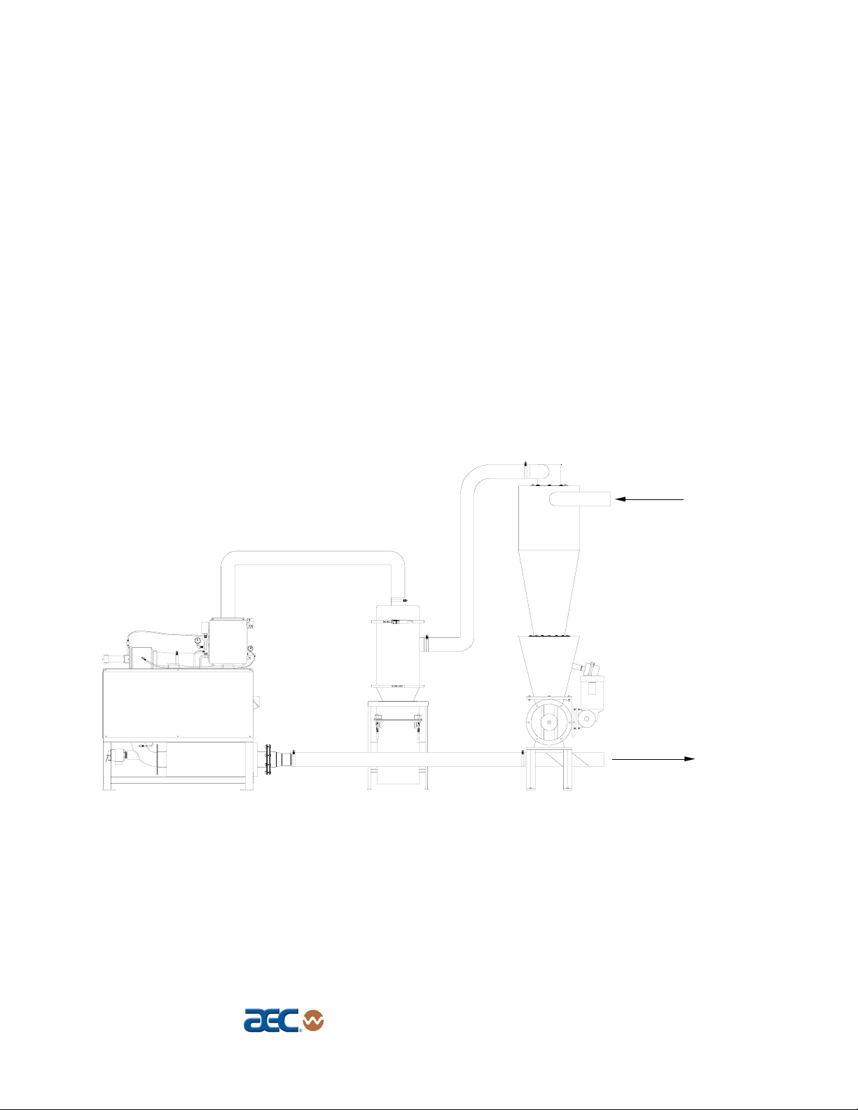
Figure 1
Typical Single Blower System for Free-Flowing Pellets
Product from
rail car
Page 10
Product
to silo
Single- and Dual-Blower Continuous Vacuum/Pressure Systems
Page 12
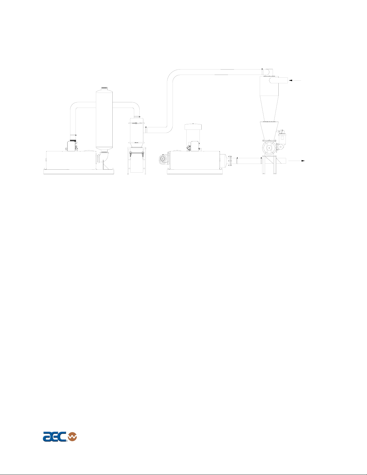
Figure 2
Typical Dual Blower System for Free-Flowing Pellets
1-3 Necessary Documents
The following documents are necessary for the installation, operation, and maintenance
of your single- or dual-blower vacuum/pressure system. You can obtain additional
copies from AEC, Inc. You should be familiar with these documents:
Product from
rail car
Product
to silo
; This manual
; Electrical connection diagram
; Electrical schematic drawing
; Final assembly drawings for vacuum and pressure units
; Manufacturer’s operation and installation manuals for rotary valve and filter
; Operation and installation manuals for accessories and options selected by the
customer, where available
1-4 Standard Features
• Continuous vacuum power unit
• Cyclone separator or filter receiver
• Rotary valve and blow-through adapter
• Continuous pressure unit
Single- and Dual-Blower Continuous Vacuum/Pressure Systems Page 11
Page 13

1-5 Options
Single-blower vacuum/pressure systems and dual-blower continuous vacuum and/or
pressure systems are used with companion equipment including cyclones, filter
chambers, rotary airlock valves, and aftercoolers. In addition, the following options are
offered:
; Sound enclosures
; Diverter valves, with or without controls
; Stainless steel cyclone
; Stainless steel pressure takeoff
; Stainless steel filter receivers
; Filter chamber stand
; Common skid for mounting filter chamber, cyclone separator, rotary valve,
discharge adapter, and single-blower pumps
; PLC controllers
; Aftercoolers
; Rotary valve compressed air purge
1-6 The Vacuum/Pressure Conveying System
Vacuum/pressure conveying systems are used to convey high volumes of powder or
pelletized material long distances from railcars into storage silos. They are available
with filters designed specifically for powder or other dusty materials.
Vacuum/pressure systems for powder are similar to pellet systems except they are
equipped with a filter receiver rather than a cyclone separator. This ensures separation
of the material and maximum dust control.
Page 12
Single- and Dual-Blower Continuous Vacuum/Pressure Systems
Page 14
2 Safety
2-1 Work Rules
Install, operate, and maintain this equipment according to applicable work and safety
codes for your location. This includes OSHA, CE, NEC, CSA, SPI, and many other
local, national, and international regulations. Obey these specific work rules:
Read and follow the instructions in this manual before
installing, operating, or maintaining any equipment.
Additional copies are available from AEC, Inc.
Only qualified persons should work on, or with, this
equipment.
Work only with approved tools and devices.
Disconnect and lock out power while working on this
equipment.
2-2 Tools and Equipment Needed
You’ll need the following:
• Hand tools
• Fork lift or overhead lift
• Wire, conduit, and fittings for wiring runs (if receptacle is not
already in place)
• Mounting bolts with nuts and washers
2-3 Mechanical Installation
Conveying system may be mounted on a stand, or a mezzanine.
Be sure it is securely attached and additional bracing is used if
necessary. The sections on the following pages explain general
installation rules.
Read manual thoroughly before installing
conveying system.
Use approved safety straps or chains to lift the
conveying system at the marked lifting points.
Single- and Dual-Blower Continuous Vacuum/Pressure Systems Page 13
Page 15
2-4 Safety Considerations
The terms NOTICE, CAUTION, WARNING, and DANGER
have specific meanings in this manual. See Section 12 for a
complete list of specific safety warning information.
A NOTICE is used to indicate a statement of company policy
directly or indirectly related to the safety of personnel or protection
of property.
A CAUTION indicates a potentially hazardous situation which, if
not avoided, may result in minor or moderate injury.
A WARNING indicates a potentially hazardous situation which, if
not avoided could result in death or serious injury.
A DANGER indicates an imminently hazardous situation which, if
not avoided, will result in death or serious injury. This word will
be limited to the most serious situation(s).
The term IMPORTANT emphasizes areas where equipment
damage could result, or provides additional information to make a
step or procedure easier to understand. Disregarding information
marked IMPORTANT would not be likely to cause personal
injury.
Page 14
REPORTING A SAFETY DEFECT
NOTE: If you believe that your equipment has a defect which could cause
injury, you should immediately discontinue its use and inform
AEC, Inc., at our address listed in this manual.
The principle factors which can result in injury are:
1. Failure to follow proper operating and clean-out procedures,
i.e. lockout/tagout.
2. Failure to maintain a clean and safe working environment.
Single- and Dual-Blower Continuous Vacuum/Pressure Systems
Page 16

2-5 General Responsibility
NO MATTER WHO YOU ARE…
Safety is important. Owners, operators, and maintenance
personnel must realize that every day, safety is a vital aspect of
their jobs.
If your main concern is loss of productivity, remember this:
Production is always affected in a negative way following an
accident. The following are some of the reasons, which can affect
your production:
• Loss of a skilled operator (temporarily or permanently)
• Breakdown of shop morale
• Costly damage to equipment
• Down-time
An effective safety program is responsible and economically
sound.
Organize a safety committee or group, and hold regular meetings.
Promote this group from the management level. Through this
group, the safety program can be continually reviewed,
maintained, and improved. Keep minutes or a record of the
meetings.
Hold daily equipment inspections in addition to regular
maintenance checks. You will keep your equipment safe for
production and exhibit your commitment to safety.
Please read and use this manual as a guide to equipment safety.
This manual contains safety warnings throughout, specific to each
function and point of operation.
2-6 Operator Responsibility
The operator’s responsibility does not end with efficient
production. The operator usually has the most daily contact with
the conveying system and intimately knows its capabilities and
limitations.
Plant and personnel safety is sometimes forgotten in the desire to
meet incentive rates, or through a casual attitude toward machinery
formed over a period of months or years. Your employer probably
has established a set of safety rules in your workplace. Those
rules, this manual, or any other safety information will not keep
you from being injured while operating your equipment.
Single- and Dual-Blower Continuous Vacuum/Pressure Systems Page 15
Page 17

REMEMBER:
ONLY YOU can make safety work for you by constantly thinking
about what is safe and what is not. It is often the “just once” that
an operator reaches into a conveying system to remove material
and it results in serious injury.
Learn and always use safe operation. Cooperate with co-workers
to promote safe practices. Immediately report any potentially
dangerous situation to your supervisor or appropriate person.
• NEVER place your hands or any part of your body in any
dangerous location.
• NEVER operate, service, or adjust the conveying system
without appropriate training and first reading and
understanding this manual.
• NEVER try to pull material out of the conveing system with
your hands while it is running!
• Before you start the conveying system check the following:
• Remove all tools from the conveying system;
• Be sure no objects (tools, nuts, bolts, clamps, bars)
are laying in the hopper area;
• If your conveying system has been inoperative or
unattended, check all settings before starting the unit.
• At the beginning of your shift and after breaks, verify
that the controls and other auxiliary equipment are
functioning properly.
• Keep all safety guards in place and in good repair.
NEVER attempt to bypass, modify, or remove safety
guards. Such alteration is not only unsafe, but will
void the warranty on your equipment.
• When changing control settings to perform a different
mode of operation, be sure selector switches are
correctly positioned. Locking selector switches
should only be adjusted by authorized personnel and
the keys removed after setting.
• Report the following occurrences IMMEDIATELY:
• unsafe operation or condition
• unusual conveying system action
• leakage
Page 16
• improper maintenance
Single- and Dual-Blower Continuous Vacuum/Pressure Systems
Page 18

• NEVER stand or sit where you could slip or stumble
into the conveying system while working on it.
• DO NOT wear loose clothing or jewelry, which can
be caught while working on the conveying system. In
addition, cover or tie back long hair.
• Clean the conveying system and surrounding area DAILY, and
inspect the machine for loose, missing or broken parts.
• Shut off power to the conveying system when it is not in use.
Turn the switch to the OFF position, or unplug it from the
power source.
2-7 Maintenance Responsibility
Safety is essential to the good health of both operator and machine.
If you are a maintenance worker, you must make safety a priority
in order to effectively repair and maintain equipment.
BEFORE REMOVING, ADJUSTING, OR REPLACING
PARTS ON A MACHINE, REMEMBER TO DO THE
FOLLOWING:
• TURN OFF all air and electric supplies and all accessory
equipment at the machine.
• DISCONNECT AND LOCK OUT electrical and pneumatic
power, and attach warning tags to the disconnect switch and air
shutoff valve.
When you need to perform maintenance or repair work on the
conveying system above floor level, use a solid platform or a
hydraulic elevator. If there is a permanently installed catwalk on
your conveying system, use it. The work platform should have
secure footing and a place for tools and parts. DO NOT climb on
machines or work from ladders.
If you need to repair a large component, use appropriate handling
equipment. Before you use handling equipment (portable “A”
frames, electric boom trucks, fork trucks, overhead cranes) be sure
the load does not exceed the capacity of the handling equipment or
cause it to become unstable.
Carefully test the condition of lifting cables, chains, ropes, slings,
and hooks before using them to lift a load.
Be sure that all non-current carrying parts of electrical apparatus,
electrical component enclosures, and the conveying system frame
Single- and Dual-Blower Continuous Vacuum/Pressure Systems Page 17
Page 19

2-8 Safety
2-8-1 Description and Objectives
This section includes information on safety devices and procedures that are
inherent to the Vacuum/Pressure Conveying System. This manual is not
intended to supersede or alter safety standards established by the user of this
equipment. Instead, the material contained in this section is recommended to
supplement these procedures in order to provide a safer working environment.
are correctly connected to earth ground with an electrical
conductor that complies with current codes. Install in accordance
with national and local codes, which apply.
When you have completed the repair or maintenance procedure,
check your work, remove your tools, rigging, and handling
equipment.
Do not restore power to the conveying system until all persons are
clear of the area. DO NOT start and run the conveying system
until you are sure all parts are functioning correctly.
BEFORE you turn the conveying system over to the operator for
production, verify all system enclosure panels, guards and safety
devices are in place and functioning properly.
At the completion of this section, the operator and maintenance personnel will
be able to:
• Identify and locate specific safety devices.
• Understand the proper use of the safety devices provided.
• Describe the function of the safety devices.
2-8-2 Safety Circuit Standards
Safety circuits used in industrial systems protect the operator and maintenance
personnel from dangerous energy. They also provide a means of locking out or
isolating the energy for servicing equipment.
Various agencies have contributed to the establishment of safety standards that
apply to the design and the manufacture of automated equipment. The
Occupational Safety and Health Administration (OSHA) and the Joint
Industrial Council (JIC) are just a few of the organizations that have joined
with the plastics industry to develop safety standards.
Page 18
Single- and Dual-Blower Continuous Vacuum/Pressure Systems
Page 20
Every effort has been made to incorporate these standards into the design of the
Vacuum/Pressure Conveying System; however, it is the responsibility of the
personnel operating and maintaining the equipment to familiarize themselves
with the safety procedures and the proper use of any safety devices.
2-8-3 Fail Safe Operation
If a safety device or circuit should fail, the design must be such that the failure
causes a “Safe” condition. As an example, a safety switch must be a normally
open switch. The switch must be held closed with the device it is to protect. If
the switch fails, it will go to the open condition, tripping out the safety circuit.
At no time should the safety device fail and allow the operation to
continue. For example, if a safety switch is guarding a motor, and the safety
switch fails, the motor should not be able to run.
2-8-4 Safety Device Lock-Outs
Some safety devices disconnect electrical energy from a circuit. The safety
devices that are utilized on this equipment are primarily concerned with the
pneumatics and electrical power disconnection, and the disabling of moving
parts that may need to be accessed during the normal operation of the machine.
Some of the safety devices utilize a manual activator. This is the method of
initiating the safety lock out. This may be in the form of a plug, disconnect
plug, lever or a handle. Within this lockable handle, there may be a location for
a padlock. Personnel servicing the equipment should place a padlock in the
lockout handle.
WARNING! Always disconnect and lockout all electrical power and pneumatic
(i.e. compressed air) sources prior to servicing or cleaning any
Vacuum/Pressure Conveying System. Failure to do so may result
in serious injury.
At no time must anyone remove the lockout or reconnect the twist
plug, other than the person who installed the lockout or who
unplugged the twist plug.
2-8-5 Lock-Outs, Plugs, and Other Safety Devices
The Vacuum/Pressure Conveying System utilizes several types of
safety devices.
The Line Cord Plug
This line cord plug allows the operator or maintenance personnel
to unplug the conveying system from its power source and tag it
out. This plug may be tagged with any number of approved
Single- and Dual-Blower Continuous Vacuum/Pressure Systems Page 19
Page 21

WARNING!
electrical lockout tags. These tags are available at most electrical
supply stores.
Disconnect both of these items to ensure optimum maintenance
personnel safety when cleaning or servicing this equipment.
-Notes-
Page 20
Single- and Dual-Blower Continuous Vacuum/Pressure Systems
Page 22
3 Shipping Information
3-1 Unpacking and Inspection
You should inspect your AEC vacuum/pressure system and components for possible
shipping damage. If the container and packing materials are in re-usable condition, save
them for reshipment if necessary.
Thoroughly check the equipment for any damage that might have occurred in transit,
such as broken or loose wiring and components, loose hardware and mounting screws,
etc. In case of breakage, damage, shortage, or incorrect shipment, refer to the following
sections.
3-2 In the Event of Shipping Damages
Important!
According to the contract terms and conditions of the Carrier,
the responsibility of the Shipper ends at the time and place of
shipment. The Carrier then assumes full responsibility of the
shipment.
; Notify the transportation company’s local agent if you discover
damage.
; Hold the damaged goods and packing material for the examining
agent’s inspection. Do not return any goods to AEC, Inc. before the
transportation company inspection and authorization.
; File a claim against the transportation company. Substantiate the claim
by referring to the agent’s report. A certified copy of our invoice is
available upon request. The original Bill of Lading is attached to our
original invoice. If the shipment was prepaid, write us for a receipted
transportation bill.
; Advise AEC, Inc. regarding your wish for replacement and to obtain an
RMA (return material authorization) number.
Parcel Post Shipment
; Notify AEC, Inc. at once in writing, giving details of the loss or
damage. This information is required for filing a claim with our
insurance company.
Single- and Dual-Blower Continuous Vacuum/Pressure Systems Page 21
Page 23

; Hold the damaged goods with the container and packing materials for
possible inspection by postal authorities.
United Parcel Service
; Contact your local UPS office regarding damage and insurance claims.
; Retain the container and packing.
; Notify AEC, Inc. at once.
3-3 If the Shipment is Not Complete
Check the packing list. The apparent shortage may be intentional. Back-ordered items
are noted on the packing list. You should have:
; AEC vacuum/pressure system and related system components
; Bill of lading
; Packing list
; Operating and Installation packet
; Electrical schematic and panel layout drawings
; Component instruction manuals
Re-inspect the container and packing material to see if you missed any smaller items
during unpacking. Determine that the item was not inadvertently taken from the area
before you checked in the shipment. Notify AEC, Inc. immediately of the shortage.
3-4 If the Shipment is Not Correct
If the shipment is not what you ordered, contact AEC, Inc. immediately. Include the
order number and item. Hold the items until you receive shipping instructions.
3-5 Returns
Important!
Do not return any damaged or incorrect items
until you receive shipping instructions from AEC, Inc.
Page 22
Single- and Dual-Blower Continuous Vacuum/Pressure Systems
Page 24

4 Installation
4-1 Work Rules
The installation, operation, and maintenance of this equipment must be conducted in
accordance with all applicable work and safety codes for the location where it is used.
This may include, but is not limited to, OSHA, NEC, CSA, SPI, and any other local,
national, and international regulations. In addition, observe the following specific
rules:
; Always keep these operating instructions at hand and follow them when
performing installation, operation, and maintenance. If these instructions
become damaged or unreadable, obtain additional copies from AEC, Inc.
; Only qualified personnel must work on or with this equipment.
; Work shall be done only with approved tools and devices.
; The power disconnect of this unit has a lockout that permits the switch to be
locked in the
must be locked out when performing maintenance or service on any part
of the conveying system, in accordance with applicable safety regulations.
OFF position when placing a padlock in the hasp. This switch
; In units that require compressed air, disconnect the compressed air supply
before performing maintenance or service.
; Disconnect and/or lock out the power main at an external power disconnect
switch before performing electrical service.
; Keep hands, tools, clothing, etc. away from the rotary valve. Make sure the
valve has completely stopped before performing maintenance.
4-2 Tools and Equipment
You’ll need the following tools and equipment to install system components:
; Hand tools
; One-half inch (
washers, and red-head type anchors, if used
; Electric drill
; Wire for connecting the power units, rotary airlock, and level indicator
; Wire and a properly-sized fused disconnect switch for the power drop(s)
; Conduit for the power drop and airlock motor wiring
1
/2”) and three-eighths inch (3/8”) anchor bolts with nuts and
; Forklift
Single- and Dual-Blower Continuous Vacuum/Pressure Systems Page 23
Page 25

4-3 Installing Mechanical Components
4-3-1 Installing Vacuum and Material Tubing
Use the following as a general reference when installing your system:
• Refer to the assembly prints often.
• Support overhead tubing about every ten (10) feet (3 m) with straps, pipe
hangers, or brackets. Keep the coupled joints rigid to avoid vacuum or
material leaks from tubing movement or misalignment.
• Cut all tube ends square, and chamfer internal edges smooth. Make sure
that the tube ends butt together inside the coupler.
• Tighten coupler nuts with a wrench to help provide a vacuum and
material-tight seal and proper contact of the internal grounding strip.
• If you must cut bends, do so on the straight section at either end, and
leave enough straight length for adequate insertion in the coupler.
• Make sure that material flow is in the direction of the arrows on flexible
material hose.
Figure 3
Examples of Single Line and Multiple Line Hangers
Page 24
Single- and Dual-Blower Continuous Vacuum/Pressure Systems
Page 26

4-3-2 Using Quick-Change Couplers and Flexible Material Hose
You can attach a quick-change coupler or standard tube coupler to the tube at
either end of the flexible material hose. Make sure that the material flow is in
the direction of the arrows on the flexible material hose. The tube on each end
of a flexible vacuum hose should fit the tube coupler for the system. You can
also fit a quick-change coupler to either tube.
If your system requires a quick-change rack, hold the rigid tubing in place with
U-clamps. Mount male quick-change couplings on the rigid piping of a quickchange rack. As your installation requires, bolt the rack in position to the wall
or floor before attaching the tubing.
Mount female quick-change couplers on the flexible hose of a quick-change
rack, allowing the ease and flexibility of selecting material flows or vacuum
flows, depending upon the requirements of your system design.
Figure 4
Quick Change Couplers
Single- and Dual-Blower Continuous Vacuum/Pressure Systems Page 25
Page 27

4-3-3 Sheltering System Components
If the power unit, control unit, rotary valve, filter, and related equipment are
not installed inside the plant, provide a weather shed or other outbuilding to
shelter these components from the weather. You should provide such shelter
even with the NEMA 4 control option.
4-3-4 Installing the Vacuum and/or Pressure Units
1. Level and secure the vacuum and/or pressure units.
2. Check oil level in blower assembly.
4-3-5 Installing the Rotary Airlock/Cyclone Assembly
Each AEC cyclone separator comes complete with a throw-out cone for
efficient material to air separation and a rotary level indicator for a high level
cut-off.
An airlock is a precision piece of equipment operating with small internal
clearances. The airlock should be bolted to the discharge adapter supported
securely on a flat surface with sponge rubber gasket provided with the
equipment.
Though they are an integral part of a vacuum/pressure system, rotary airlocks
are specified separately to meet the exact requirements of the materials
conveyed. Refer to the separate guide the airlock manufacturer has included on
airlock installation and maintenance.
1. Level and secure the vacuum unit, pressure unit, and blow-through adapter
with stand to the floor using one half-inch (
1
/2”) bolts.
2. Bolt the rotary airlock and motor assembly you specified to the blow-
through adapter, if not already done at the factory. Use the one eighth inch
(1/8”; about 3 mm) -thick composite gaskets provided.
3. Tighten the bolts evenly to avoid distortion of the flanges. Draw up snug—
do not over-tighten. Exerting twisting or pulling pressure on the housing, as
with poor installation of related components, causes damage, excessive
wear, and air leaks.
Note: Verify that the rotation of the airlock is toward the larger, square-cornered outlet
of the blow-through adapter. See Figure 6 on Page 33 for more information.
4. Install the shear protector on top of the rotary valve.
Page 26
Single- and Dual-Blower Continuous Vacuum/Pressure Systems
Page 28

WARNING!
Note:
Shear points are present at the
open inlet and outlet of the rotary airlock.
For safety, you must cover the inlet and outlet
before performing this procedure!
THE AIRLOCK COULD SHEAR OFF YOUR FINGERS
if you do not take adequate safety measures!
HAND GUARDS ARE REQUIRED.
• The rotary airlock is a precision-machined device. Exerting twisting or
pulling pressure on the housing (as with poor installation of related
components) causes damage, excessive wear, and air leaks.
• The shaft seals are shipped loose and must be tightened before running
material through the airlock.
5. Install and/or inspect the optional rotary level indicator.
6. Mount the cyclone on top of the rotary airlock. The legs provided to the
airlock support the entire assembly. If the self-cleaning filter is purchased,
mount the airlock with the blow-through adapter to the discharge flange of
the filter receiver. The airlock/blow-through adapter can be oriented so the
airlock housing does not interfere with the filter receiver legs. Use the one
eighth inch (
evenly to avoid distorting flanges. Draw up snug—do not over-tighten.
7. Take care to align the pressure blower discharge muffler and the blow-
through adapter. Airlocks are precision-machined devices. Do not load or
twist the housing.
8. Connect the discharge end of the pressure blower to the inlet side of the
discharge adapter. Black heavy-duty high-temperature oil-resistant hose is
provided for the connection.
1
/8”; about 3 mm) -thick composite gaskets. Tighten bolts
Single- and Dual-Blower Continuous Vacuum/Pressure Systems Page 27
Page 29

Figure 5
Rotary Airlock/Cyclone Assembly
Product from
rail car
High Level Switch
(option)
Product
to silo
9. Complete the pressure-side material line between the outlet side of the
blow-through adapter and the material destination. Connect the pressure
side material line to the blow-through adapter on the larger, squarecornered, tapered side. See Figure 11 on Page 40 for more information.
10. Complete the material line connections from the material manifold line or
the material source to the inlet of the cyclone separator or self-cleaning
filter.
11. Complete the vacuum line connections from the vacuum unit to the filter
chamber (in pellet conveying systems) and to the cyclone separator. In a
powder conveying system, no cyclone separator or vortex filter chamber is
provided. Complete the vacuum line connections from the pump to the
outlet tube on the self-cleaning filter.
12. Check oil level in airlock gear reducer assembly.
CAUTION! When connecting the material line, make sure it
is supported and no load is placed on the rotary airlock!
Page 28
Single- and Dual-Blower Continuous Vacuum/Pressure Systems
Page 30

IMPORTANT! The power unit is sized for the total conveying distance.
In some cases, if the takeoff on the railcar does not have an
adjustment to restrict material flow into the vacuum side
material line, too much material may be drawn on the vacuum
side.
A solution for this condition is to install a manual valve
on a T in the material line as close to the take-off as possible.
Throttle this valve to supply some of the air requirement
of the vacuum unit to prevent excess material from plugging
the line.
4-3-6 Installing the Filter Chamber
Used in Combination with the Cyclone Separator Only
The filter chamber protects the vacuum blower from damage caused by
material carryover from the cyclone separator. Primary system filtration
occurs in the cyclone separator and any fines that are carried over to the
filter chamber are trapped in the cartridge filter in the filter chamber.
A vortex created in the filter chamber separates carryover from the air
stream, and a cartridge filter catches any dust and any fines into the upper
chamber. If used in a very dusty application the filters can be cleaned in
any one of the following ways:
• Install an atmospheric vent valve on the outlet of the filter chamber.
During the blowback cycle, when the valve is energized,
atmospheric air is introduced to the filter chamber, equalizing the
pressure inside the filter chamber with a rush of air across the filter.
• A compressed air filter cleaning blowback option is used for very
dusty applications, and cleans better than the option listed above.
1. Level and secure the filter chamber near the pump package. Use three
eighths-inch (
3
/8”) bolts to anchor the filter chamber.
2. Connect the piping between the vacuum inlet valve on the pump and
the outlet tube on the cover of the filter chamber. For easy filter
maintenance, use at least three (3) feet (1 m) of vinyl flex hose at the
end of the run to the filter chamber. The rest can be hard-piped as long
as it is properly supported.
3. If the filter chamber has the optional atmospheric valve, insert a short
piece of chamfered tubing into the valve body inlet, tighten the set
screws, and connect the flex hose to the tube with a clamp.
Single- and Dual-Blower Continuous Vacuum/Pressure Systems Page 29
Page 31

4. Connect the inlet tube of the filter chamber to the outlet of the cyclone
separator.
4-3-7 Installing the Filter Chamber Shroud
The cloth filter shroud is mounted to a ring on the underside of the filter
chamber stand. It reduces housekeeping duties around the filter chamber by
preventing dust from being stirred up when the dust and fines are discharged
from the VFC filter chamber. The dust container below the shroud is customersupplied—the standard 24” (61 cm) clearance stand is designed for use with a
5-gallon (19-liter) pail, and the optional 38” (96 cm) clearance stand is
designed for use with a 55-gallon (208-liter) drum.
1. Insert the filter shroud support wire into the slotted hole in the middle
of the cloth filter shroud. Use supplied hardware to secure.
2. Slip the filter shroud over the retaining ring located on the bottom side
of the filter stand mounting plate. Secure it with the worm clamp
provided.
3. Place the dust container you’ve supplied below the filter chamber
stand and insert the filter shroud.
4. On standard 5-gallon (19-liter) pails, the filter shroud should be
trimmed to project about one half of the way into the container. Don’t
trim the filter shroud on 55-gallon (208-liter) drums. Secure the
drawstring on the shroud around the drum, making sure the open end
of the shroud hangs freely inside the drum.
5. Make sure the operation of the counterweighted flapper dump valve is
not obstructed in any way by the filter shroud.
CAUTION! Do not obstruct the filter shroud in any way.
Empty the dust container before
the dust level obstructs the end of the filter shroud.
4-4 Making Compressed Air Connections
Note: If the system you specified uses a vacuum unit with non-reversing valving for
blowback, you must connect the vacuum unit to a source of clean, dry, lubricated
compressed air with an operating pressure of 80 psig (551.6 kPa/5.52 bars).
Page 30
CVP/CPP Systems
CVP/CPP systems do not require compressed air connections at the pumps.
Single- and Dual-Blower Continuous Vacuum/Pressure Systems
Page 32

SVP Systems
Connect the pump to a minimum of 80 psi (551.6 kPa/5.52 bars) clean, dry,
lightly lubricated compressed air. Make
package.
the 1/8” NPT connection at the pump
4-5 Making Electrical Connections
Single-blower vacuum/pressure systems and dual-blower continuous vacuum and/or
pressure systems require connection to a 3-phase power supply. The control unit is
mounted on the vacuum unit or mounted in a remote location. Refer to local electrical
codes and the connection diagram and schematic enclosed with the unit.
Note: Refer to the specific electrical schematic included in your Customer Information
Packet when making electrical connections. Make sure all electrical connections
are tight.
Use the following as a general reference:
Power Drop
Check the nameplate voltage and amperage on the control unit and on each motor
in the system. Voltage must be within plus or minus five percent (±5%) of the
nameplate voltage.
• Bring properly sized power leads, in conduit, to the control unit. Bring power
through a properly-sized fused disconnect switch with approved lockout,
supplied by the customer.
• Ground the control unit for operator safety and equipment protection.
Rotary Airlock Motor
Run three wires from the rotary airlock motor back to the control unit.
IMPORTANT! Make sure the motor leads are connected so the rotary airlock
rotates in the proper direction. Refer to the electrical
schematic included in your Customer Information Packet to
verify terminal connection points.
Reverse any two motor leads to change direction.
See Figure 7 on Page 34 and Figure 9 on Page 36 for more
information.
Single- and Dual-Blower Continuous Vacuum/Pressure Systems Page 31
Page 33

Vacuum Unit Motor
If the control unit is mounted on the vacuum unit, the vacuum unit motor is prewired to the control unit. If the control unit is remotely mounted, bring three
properly sized leads in conduit from the terminals in the small junction box on the
vacuum unit to the control unit.
Check for proper motor rotation direction. Reverse any two motor leads to
change direction.
Pressure Unit Motor
Bring three properly sized leads in conduit from the terminals in the small junction
box on the pressure unit to the control unit. Check for proper motor rotation
direction. Reverse any two motor leads to change direction.
Vacuum Solenoid Valves (Single Blower Units, SVP Models)
If the control unit is mounted on the vacuum unit, these valves are pre-wired. If the
control unit is remotely mounted, connect three 14-gauge 300V MTW wires and
bring them in conduit to the vacuum unit junction box.
High Vacuum Switch
If the control unit is mounted on the vacuum unit, this switch is pre-wired. If the
control unit is remotely mounted, connect two 14 gauge 300V MTW wires and
bring them in through the conduit to the vacuum unit junction box.
High Pressure Switch
Run two 14 gauge 300V MTW wires from the control unit to the junction box on
top of the pressure unit. For solid state control units, connect the wires in both the
control unit and junction box. For relay units, connect the wires as shown in the
electrical schematic included in your Customer Information Packet.
High Level Switch
Provision for a single high level switch at the material receiving point is standard.
Run two 14 gauge 300V MTW wires from the switch to the control unit on
conduit. Where optional switch-selectable high level sensors are present, refer to
the connection diagram enclosed with this manual for terminal numbers.
Cyclone High Level Sensor
Run two 14 gauge 300V MTW wires from the sensor to the control unit in conduit.
4-6 Testing the Rotary Airlock
Page 32
Run the airlock motor and airlock, verifying that the airlock is turning in the proper
direction (See Figure 6). Measure the current draw with a clamp-on ammeter and
compare it with the rated draw on the motor nameplate.
Single- and Dual-Blower Continuous Vacuum/Pressure Systems
Page 34

Gradually and evenly tighten the packing gland bolts on either side of the rotor until the
A
w
A
w
motor current draw is about eighty percent (80%) of the rating listed on the motor
nameplate.
Run the airlock motor and airlock for thirty (30) minutes. Again, tighten the packing
gland bolts until the motor current draw is about eighty percent (80%) of the rated draw
of the motor.
Figure 6
Rotary Airlock Rotation and Material Flow
Shear Protector
Opening
Motor
Pressure
take-off
ir flo
ir flo
Note: Make sure the shear protector (pellet valve) is installed on top of rotary valve in
all pellet systems. Opening should be located above downward side of rotation.
Single- and Dual-Blower Continuous Vacuum/Pressure Systems Page 33
Page 35

Figure 7
Typical SVP System Electrical Schematic
Page 34
Legend
------- Field wiring
Terminal Block
Notes:
1. 1PS opens on high pressure.
2. 1LS opens on throw-out cone high level.
3. 1VS closes on high vacuum.
4. 2LS closes on high level in silo.
Single- and Dual-Blower Continuous Vacuum/Pressure Systems
Page 36

Transformer,
460 V to 115 V
Figure 8
Typical SVP Electrical Subpanel Layout
Fuse holder,
30 amp fuses
Disconnect
switch
Relay
60 sec.
timers
Overload
contactor
Overload
contactor
Terminal blocks
Single- and Dual-Blower Continuous Vacuum/Pressure Systems Page 35
Page 37

Figure 9
Typical CVP/CPP System Electrical Schematic
Page 36
See Note #3
(typical)
Legend
----------------- Field Wiring
Indicates terminal block connection
Notes:
1. 1PS opens on high pressure,
2. 1LS opens on cyclone separator high level.
3. 2LS closes on high level of its respective silo.
4. 1VS closes on high vacuum.
Single- and Dual-Blower Continuous Vacuum/Pressure Systems
Page 38

Figure 10
Typical CVP/CPP Electrical Subpanel Layout
Fuse holder,
30 amp fuses
Transformer,
460 V to 115 V
Relay
60 sec.
timers
Disconnect
switch
Overload
contactor
Overload
contactor
Terminal blocks
Single- and Dual-Blower Continuous Vacuum/Pressure Systems Page 37
Page 39

- Notes -
Page 38
Single- and Dual-Blower Continuous Vacuum/Pressure Systems
Page 40

5 Startup, Shutdown, and Operation
5-1 Equipment Cycle
Systems with dual blowers have a slightly different equipment cycle than systems with
single blowers. Refer to electrical schematic and panel layout drawings included with
your system for more information.
A description of the cycles for each type follows:
SVP — Single Blower Vacuum Pressure Systems
When the system is started, the single vacuum/pressure blower and the rotary airlock
activate. The blower draws air from the atmosphere (goes into a vent cycle) and starts
to purge the pressure side material line for a set period of time as determined by the
vacuum on delay timer. After a set time period, the vent cycle ends and material is
drawn into the cyclone, where it is stripped from the conveying air and drops into a
rotary airlock.
The airlock allows material to pass to the pressure side of the system where it is blown
to the destination. The SVP blower replaces CVP/CPP blowers in single blower
vacuum pressure systems, but the load cycle remains the same. See Figure 11 on Page
40 for more information.
When the system is stopped in a non emergency situation (purge stop), the blower goes
into the Vent cycle and continues to purge the material in the pressure side of the
material line, while no material is drawn into the cyclone separator or the filter receiver.
The purge time controlled by the purge timer, adjustable from zero to ten (0-10)
minutes. You must restart the system after the purge cycle.
When level sensors in the cyclone or at the destination point detect a high level
condition, the vacuum unit goes into idle until material levels decline. The time for the
idle state is controlled by the Vacuum On delay timer, adjustable from zero to ten (0-
10) seconds. The system then returns to the conveying cycle. An automatic shutdown
module shuts down the vacuum/pressure blower and rotary airlock after a preset period.
The emergency stop button on the control unit shuts down all units in the system. The
system also goes into emergency stop when the high pressure sensor on the pressure
outlet opens.
Single- and Dual-Blower Continuous Vacuum/Pressure Systems Page 39
Page 41

CVP/CPP — Dual Blower Vacuum Pressure Systems
When the system is started, the pressure blower and rotary airlock energize and the
pressure blower starts to purge pressure-side material lines and builds up speed. At the
end of the period preset on a vacuum on delay timer, the vacuum blower energizes.
Material is drawn to the filter receiver or cyclone where it is stripped from the
conveying air and drops into a rotary airlock.
When the system is stopped in a non-emergency situation (purge stop), the vacuum unit
stops and allows the rotary airlock and pressure unit to continue conveying material,
purging pressure-side material lines. The purge timer shuts down the pressure unit and
rotary airlock after a preset period.
The system also goes into purge stop when level sensors in the cyclone, filter chamber,
or at the destination point detect a high level condition. You must restart the system
after the purge stop cycle.
The emergency stop button on the control unit shuts down all units in the system. The
system also goes into emergency stop when the high pressure sensor on the pressure
outlet senses high pressure.
Figure 11
Typical Vacuum/Pressure System Load Cycle
Page 40
Single- and Dual-Blower Continuous Vacuum/Pressure Systems
Page 42

Notes: The drawing on the previous page shows a typical CVP/CPP system for conveying
plastic pellets. For dusty material applications, replace the cyclone separator/filter
chamber combinations with one self-cleaning filter chamber.
In SVP systems, an SVP blower is used in lieu of CVP/CPP combination blowers.
5-2 Alarms, Controls, and Indicators
Single- and dual-blower vacuum/pressure systems include the following controls and
indicators:
Controls
Disconnect (DISC)
Position the disconnect switch to turn electrical power to the system on and off.
Start (1PB)
Push Start to start the system. The system does not start if blower or airlock
motor overloads have tripped out.
Emergency Stop (2PB)
Push Emergency Stop to completely stop system functions in an emergency.
Do not use it for normal system shutdown.
Purge Stop (3PB)
Push Purge Stop to shut down the system normally. The system ends vacuum
conveying while allowing the pressure side to empty the cyclone or filter
receiver, blowing material out the pressure side. The automatic shutdown module
in solid state units or purge timer in relay units controls the shutdown period.
Indicators
Power On Pilot Light (1LT)
Power On illuminates when the system energizes.
Purge Pilot Light (2LT)
Purge illuminates when the vacuum unit stops and the rotary airlock and
pressure unit purge the pressure-side material line.
Convey Pilot Light (3LT)
Convey illuminates when the system starts and the vacuum side conveys
material.
Single- and Dual-Blower Continuous Vacuum/Pressure Systems Page 41
Page 43

Figure 12
Typical SVP Control Panel Layout
Disconnect
POWER
POWER switch
PURGE switch
R
PURGE
A
_
O
F
N
O
F
0
STOP switch
PURGE
SILO
1 2
START
PURGE STOP switch
PURGE switch
START switch
Silo selector switch
Page 42
42079Q91
Single- and Dual-Blower Continuous Vacuum/Pressure Systems
Page 44

Figure 13
Typical CVP/CPP Control Panel Layout
POWER switch
PURGE switch
CONVEY switch
EMERGENCY STOP switch
POWER
1LT
PURGE
2LT
CONVEY
3LT
E.STOP
START
2PB 1PB
PURGE
STOP
3PB
START switch
PURGE STOP switch
O
F
F
1DISC
N
O
Disconnect
SILO
1 2
Silo selection switch
41275Q91
Single- and Dual-Blower Continuous Vacuum/Pressure Systems Page 43
Page 45

5-3 Mechanical Indicators and Safety Features
Single-blower vacuum/pressure systems and dual-blower continuous vacuum and/or
pressure systems include the following components. Proper operation of the system
depends on your adjusting them to your specific material and application.
DANGER!! You must perform some adjustments
inside the control cabinet with power
ON.
USE EXTREME CAUTION in such
circumstances.
Only qualified personnel who
understand the equipment and who
know the hazards can be allowed to
perform such procedures.
HIGH VOLTAGE MAY BE PRESENT,
WHICH CAN CAUSE SEVERE INJURY
OR DEATH!
BE SAFETY CONSCIOUS!
Vacuum Gauge
The vacuum gauge indicates the operating vacuum on the vacuum side of the
system. It should read up to 10 in. Hg (339 millibars) during normal operation.
It is connected to the cross tee above the blower.
Pressure Gauge
This gauge indicates the operating pressure on the pressure side of the system. It
should read up to 5 psig (34.475 kPa/0.344 bars) during normal operation. It is
located directly in front of the pressure switch.
High Vacuum Switch (1VS)
The vacuum switch protects the vacuum pump from high amperage damage if a
material blockage should occur during conveying. It is located in the junction
box on the standard vacuum pump.
Page 44
Single- and Dual-Blower Continuous Vacuum/Pressure Systems
Page 46

IMPORTANT!
Pressure Switch
The vacuum/pressure system shuts down if the vacuum switch senses vacuum
greater than 14 in. Hg (406.8 millibars). The vacuum switch is nonadjustable
and therefore needs no adjustment.
The most common cause of high vacuum is plugged filters. When system
vacuum rises above the setting on the switch, the switch closes and begins the
purge cycle. After a preset time, the whole system shuts down.
Do not tamper with the vacuum switch.
Doing so voids your vacuum pump warranty!
The pressure switch protects the pressure pump from high amp damage if a
material line blockage occurs during conveying. The pressure pump shuts down
if the pressure switch senses air pressure greater than 6 psig (41.37 kPa/0.414
bars).
The pressure switch is adjusted at the factory and needs no adjustment.
IMPORTANT!
Pressure Relief Valve
Do not attempt to adjust the pressure switch.
It was pre-set at the factory.
Doing so voids your pressure pump warranty!
The adjustment for pressure relief is factory-set at about 1 psig (about 7 kPa/70
millibars) above the maximum allowable pressure set on the pressure switch. It
is located on the pressure unit.
The main cause for high pressure is a blocked material line on the pressure
side. When air pressure overcomes the spring tension on the mechanical
adjustment, the valve opens and relieves the pressure. The pressure relief valve
serves as a mechanical backup for the pressure switch. The pressure switch
should trip and shut down the pressure pump before the pressure relief valve
opens.
Single- and Dual-Blower Continuous Vacuum/Pressure Systems Page 45
Page 47

IMPORTANT! Do not attempt to adjust the relief valve
to more than 1 psig (about 7 kPa/70 millibars)
above the maximum operating pressure
for your system (typically 7 psig or about 48.265 kPa/0.482
bars).
Doing so voids your pressure pump warranty!
Vacuum Vent Valve
SVP Pumps Only
When the purge button is pressed, the solenoid valve on the vent valve
energizes and the cylinder opens to draw vacuum from the atmosphere instead
of from the vacuum line. The vent valve breaks the vacuum, but supplies air to
purge material on the pressure side of the material line.
Vacuum On Delay Timer
1TR
Set the Vacuum On delay timer. It controls how long the vacuum blower is in
the idle state (SVP systems) or in the shutoff mode (CVP/CPP systems) before
resuming normal convey cycle. Set it so material can clear from the cyclone
separator or filter receiver before it is conveyed again. Timer range is zero to ten
(0-10) seconds.
Auto Shutdown Timer or Purge Timer
Set this timer to control how long the pressure unit continues to operate after
you press Purge Stop (3PB). Allow the unit to run long enough to empty the
cyclone/filter receiver, blow-through adapter, and the entire pressure side
material line.
If material is left in the pressure line when the system is shut down, it tends to
plug the line when you restart the system. When adjusting this time to your
application, start with the timer at the maximum setting and work back to the
optimum time. Turn it clockwise to increase the setting. When the timer times
out (zero to ten [0-10] seconds), the entire system shuts down. With SVP
systems, the pump goes into a vent cycle while it purges the pressure side of the
material line. In CVP/CPP systems, the vacuum pump shuts down while the
pressure motor runs for a preset time as determined by the purge timer.
Blowback Timer
Refer to the electrical schematic enclosed in the Customer Information Packet
for adjusting blowback on/off pulses and the duration of each pulse.
Page 46
Single- and Dual-Blower Continuous Vacuum/Pressure Systems
Page 48

Silo Selector Switch
AEC vacuum/pressure pumps are equipped with a silo selector switch. This
switch is wired to the high level switches inside individual silos, and selects
which high level sensor is monitored. Wire this switch according to the wiring
diagram and schematic.
Turn the silo selector switch indicator to the silo currently being filled by the
vacuum/pressure blower(s). When the selected high level silo indicator senses a
full silo, a purge stop cycle actuates.
Your AEC vacuum/pressure pump(s) package comes standard with a twoposition selector switch. More than two positions are available; stipulate the
number of positions you want when ordering.
5-4 Pre-Startup Checklist
Before operating the system, verify the following areas:
; Verify that you made a solid compressed air connection.
; Verify that you made all material, pressure, and vacuum connections and that
they are secure.
; For units equipped with a high temperature thermostat (
properly adjusted the high temperature shutdown setting.
; Verify that any companion equipment (filter receiver, cyclone, rotary airlock,
aftercooler) are ready to operate.
; Verify that the disconnect switches in your power drop and at the control
enclosure are energized.
; Verify that pump and rotary airlock are correct.
5-5 Starting the System
After you install the system and made all pre-startup checks, perform the following
procedure to start the unit:
; Make any final connections at the material source.
; Turn on compressed air.
; Press
; Make adjustments to the system (i.e. vacuum, blowback, automatic shutdown,
Start. System operation is automatic and continuous.
etc.) as needed.
1THS), verify that you
Single- and Dual-Blower Continuous Vacuum/Pressure Systems Page 47
Page 49

5-6 Shutting Down the System
In certain operating conditions, pressing Emergency Stop or Purge Stop shuts
down the system. Refer to the following sections for an explanation of the operation
and conditions of each.
Operating Conditions Shutdown
The vacuum/pressure pump(s) automatically shut(s) down in the following conditions.
High Level Signal
The level switch in the silo or throwout cone signals a full condition. A purge
stop sequence occurs and the system shuts down.
Push the Start button to re-start the system.
High Vacuum
The vacuum switch senses vacuum in excess of 12 in. Hg (406.8 millibars) on
the vacuum side of the system. The Purge Stop sequence activates and the
entire system shuts down. Find the blockage and remove it.
Push the Start button to re-start the system.
High Pressure
The pressure switch senses pressure in excess of 6 psig (41.4 kPa/0.41 bars) on
the pressure side of the system. The vacuum/pressure system shuts down. Find
the blockage and remove it.
Push the Start button to re-start the system.
Note: A high vacuum condition causes units to begin the purge cycle, interrupting
vacuum conveying. In SVP systems when the purge cycle occurs, the pump
goes into vent cycle. In CVP/CPP systems, the vacuum unit turns off for a
preset time period. A high pressure condition causes the mechanical relief
valve to open on the pressure unit, affecting pressure conveying if the high
pressure switch fails to shut down the units.
Emergency Shutdown
In an emergency, press Emergency Stop (1PB) to stop system operation. Expect to
encounter material plugging the pressure line on subsequent startups.
Normal Shutdown
Page 48
Press Purge Stop (3PB) for normal operational shutdown. Vacuum conveying stops
immediately. After the system purges the cyclone/filter receiver, blow-through adapter,
Single- and Dual-Blower Continuous Vacuum/Pressure Systems
Page 50

and pressure side material lines of material (set duration in the Auto Shutdown Timer
or Purge Timer), the pressure side of the conveying system also stops.
Maintenance and Long-Term Shutdown
When shutting down the unit for maintenance or for a long period of time, follow the
procedure listed in Normal Shutdown in the previous section. Then continue with
the following steps:
1. Open (de-energize) the disconnect switch at the control enclosure and the one
at the power drop.
2. Turn off compressed air to the unit by closing the shutoff valve in the supply
circuit.
5-7 Unloading Railcars
Refer to Appendix A on Page 57 for information on proper procedures for unloading
railcars using AEC equipment.
Single- and Dual-Blower Continuous Vacuum/Pressure Systems Page 49
Page 51

6 Maintenance
6-1 Work Rules
The installation, operation, and maintenance of this equipment must be conducted in
accordance with all applicable work and safety codes for the location where it is used.
This may include, but is not limited to, OSHA, NEC, CSA, SPI, and any other local,
national, and international regulations.
In addition, observe the following specific work rules:
; Always keep these operating instructions at hand, and follow them when
performing installation, operation, and maintenance. If the instructions become
damaged or unreadable, obtain additional copies from AEC, Inc.
; Only qualified personnel must work on or with this equipment.
; Perform work only with approved tools and devices.
; Refer to the Safety Label drawing included with your unit for the type and location
of equipment safety labels.
; The power disconnect of this unit has a lockout which permits the switch to be
locked in the
be locked out when performing maintenance or service on any part of the
conveying system, in accordance with applicable safety regulations.
; In units which require compressed air, disconnect the compressed air supply
before performing maintenance or service.
; Disconnect and/or lock out the power main at an external power disconnect switch
before performing electrical service.
; Keep hands, tools, clothing, etc. away from the rotary valve. Make sure the
valve is completely stopped before performing maintenance.
OFF position when placing a padlock in the hasp. This switch must
6-2 Lubricating Components
Single- and dual blower vacuum/pressure systems require the following lubrication:
Blowers
The blowers of the unit and pressure unit must be greased, and the oil in the
gearbox must be kept at the proper level. The recommended oil is listed in the
attached Blower Instruction Handbook and should be used as listed there.
Page 50
Pack the front bearings with a good, high temperature ball bearing grease, again as
listed in the blower manual.
Single- and Dual-Blower Continuous Vacuum/Pressure Systems
Page 52

Motors
No lubrication is required.
Rotary Airlock
After the first six months of operation, lubricate the airlock rotor shaft bearings with
good quality grease every three to six months at the grease fittings provided. Do not
over-lubricate!
Compressed Air Lubricator (Optional)
Check the lubricator for the vacuum unit compressed air supply daily for oil level.
Refill as needed with proper lubricant.
6-3 Periodic Service
The following section lists suggested periodic service for single- and dual-blower
vacuum/ pressure systems. The service schedule for your particular application is
determined by the material you convey and the operating environment.
Weekly Checks and Inspections
; Check motors for excessive noise or vibration.
; Check all hoses and pipe connections for tightness and leaks.
; Check all filters for dirt or wear; clean or replace as needed.
Monthly Checks and Inspections
; Check wiring for secure connections, frayed insulation, etc.
; Check the muffler on the vacuum unit for material particles that may have
plugged internal openings. This indicates poor filter maintenance at the filter
chamber or filter receiver. Fines may also enter the muffler during the
blowback cycle of solid state units if poor housekeeping conditions exist at the
unit. Material in the muffler can present a fire hazard. If you find any material,
replace the muffler.
; Check the motor and blower sheave bolts on the vacuum and pressure units.
Tighten them to 72 foot-pounds (98 N•m) of torque.
Quarterly Checks and Inspections
; Check the motor/blower drive belt on the vacuum and pressure units for signs
of wear and proper tension. Replace the belt if it shows any sign of wear.
; Clean the motor vents with a soft cloth or vacuum.
Single- and Dual-Blower Continuous Vacuum/Pressure Systems Page 51
Page 53

Periodic Checks and Inspections
; Check the solid state modules on solid state units with the optional Test Unit
as desired.
; Repair the upper or lower valve, if either malfunctions, on the vacuum unit of
solid state systems (relay systems do not have non-reversing valves).
Note: Refer to the appropriate component literature for the lubrication and maintenance of
such companion equipment as rotary airlocks, filter chambers or receivers,
aftercoolers, etc.
6-4 Maintaining Filter Chambers
VFC filter chamber maintenance is much easier if you use vinyl flex hose for making
the final connection to the cover.
To check the filter element:
1. Unlatch the clamp that secures the cover assembly.
2. Lift off the cover and look for element fouling or wear:
• If the filter is worn, replace with P/N A0547008 (VFC225) or P/N
A0547007 (VFC1000).
• If the filter is lightly soiled, remove the filter and clean with compressed
air. Blow it out from the inside.
3. To remove the filter:
• Note the orientation of the components.
• Unscrew the retaining cover.
4. Wipe down the gasket and filter retainer/VFC cover mating surfaces to ensure
a good seal.
5. Blow out the cartridge filter with compressed air. Blow from the inside out.
Make sure that compressed air pressure is less than 100 psi (689.5 kPa/6.9
bars) to keep from collapsing the filter!
6. Re-install the filter and filter retainer. Do not over tighten the retainer. A snug
fit is required for a proper seal.
7. Secure the cover assembly with the clamp.
• Periodically inspect the flapper assembly gasket and disk for signs of
wear. A good vacuum seal is important for proper operation.
Page 52
• Periodically inspect the flapper dump assembly for proper operation. The
flapper should swing freely.
Single- and Dual-Blower Continuous Vacuum/Pressure Systems
Page 54

Note: The counterbalance should be adjusted so the flapper remains open about 1/2” (13
mm) when not under vacuum.
6-5 Service Procedures
This section lists major system service areas.
Cleaning Pressure Unit Inlet Filters
Some models have a screen over the air inlet on the upper valve. Wipe it off or
vacuum it as needed.
For other models, perform the following procedure to clean the inlet filter:
• Shut down the vacuum unit by pressing Purge Stop (3B).
• When the unit stops, open the disconnect switch (DISC) at the control
enclosure and the disconnect switch at your power drop.
• Remove the nut and washers that hold on the filter cover, and take off the
cover.
• Remove the retainer and the filter element, and separate the two.
• Wash the filter element in cold water and a mild detergent. Rinse and dry it
thoroughly before you reinstall it.
• Place the element and retainer back in the filter case and refasten the cover
with the nut.
Replacing Mufflers
The muffler is located under the vacuum unit base at the discharge of the lower
valve. Use the following procedure to replace it:
• Shut down the vacuum unit by pressing
• When the unit has stopped, open the disconnect switch (
enclosure and the disconnect switch in your power drop.
• On solid state units, turn off the compressed air to the unit.
• Remove the coupler connecting the muffler-to-line adapter to the
blowthrough adapter.
• Uncouple any copper air tube from the muffler.
Purge Stop (3B).
DISC) at the control
• Loosen the setscrews securing the valve-to-muffler adapter to the lower
valve.
Single- and Dual-Blower Continuous Vacuum/Pressure Systems Page 53
Page 55

• Remove the two self-tapping screws at the left of the unit holding the muffler
bracket to the base. Take off the muffler with adapters.
• Place a new muffler, with adapters, in position. Tighten the setscrews that
secure it to the lower valve.
• Secure the bracket to the base with the two self-tapping screws.
• Couple the muffler-to-line adapter to the blowthrough adapter.
• Reconnect any copper air tube to the muffler.
-Notes-
Page 54
Single- and Dual-Blower Continuous Vacuum/Pressure Systems
Page 56

7 Troubleshooting
When a problem is based on a pilot light, check the light bulb before performing one of these
corrective procedures.
Problem Possible cause Corrective action
The disconnect switch at the
Close (energize) the switch.
Replace the fuse(s).
Refer to the next section below.
Repair or replace the power
supply as required.
Repair or replace it as required.
Check wiring integrity and amp
draw. Reset the overloads.
Check wiring integrity, reset the
overloads, and verify amp draw.
Once the unit has completely
shut down, it may be restarted.
Repair or replace them as
required.
Clean the filters according to
the instructions in the operating
literature.
Refer to enclosed manual or
contact Service Department.
If the takeoff device cannot be
adjusted, install a valve on a T
of the material line and open it
to supply some of the air
requirements of the blower.
Check joints and connectors;
seal leaks.
Check and adjust vacuum vent
valve or Kunkle valve.
The “Power On” pilot light (3LT)
does not come on when Start
(2PB) is pressed.
The blower or airlock motors do
not run.
Vacuum conveying rate drops
off.
machine or in the power drop is
open (de-energized).
The fuse(s) in the power drop
disconnect switch have opened.
Main fuse has opened. Replace the fuse(s).
The airlock motor starter has not
energized.
The logic power supply is faulty.
The step-down former (1T) is
faulty.
The motor overloads have taken
the motor(s) off-line.
The motor overloads have taken
the motor(s) off-line.
The main fuse has opened. Replace the fuse.
The contact from the auto
shutdown module has opened.
The motor starters are faulty.
On vacuum units, filters in the
filter chamber are too dirty.
Continuous cleaning
filter/receiver has dirty filters or it
is not operational.
Material line is plugged because
too much material is being
conveyed by blower.
Air leaks in the material line.
Vacuum vent valve or Kunkle
valve is out of adjustment.
Single- and Dual-Blower Continuous Vacuum/Pressure Systems Page 55
Page 57

Problem Possible cause Corrective action
The pressure conveying rate
drops off.
The pressure side material line
has plugged.
The rotary airlock valve is not
operating.
No material is in the cyclone.
The auto shutdown module time
setting is not long enough to
clear the pressure line of
material at shutdown.
An obstruction has occurred on
the pressure side.
- Notes -
Check that the wiring has been
completed. Refer to the rotary
airlock section on the previous
page.
Make sure that the cyclone has
material.
Increase the time setting.
Check and clear obstruction.
Page 56
Single- and Dual-Blower Continuous Vacuum/Pressure Systems
Page 58

(8) Appendix A Unloading Railcars
Unloading Bulk Railcars
2” to 3” Unloading Kits
An important adjustment for successful operation of the AEC Bulk Unloading
System is setting the correct material-to-air ratio at the material pickup point in
the railcar.
Get familiar with these material pickup instructions for the various types of
railcars from which your material may be shipped. Each type of car requires a
different unloading technique for successful operation of this part of your system.
The patented probe kit consists of:
• Two (2) aluminum nozzle caps
• One (1) filter
• One (1) adapter assembly with a male quick-change coupler
• Five (5) material pick-up probes
Also included for car unloading is a length of flexible material tubing for ease of
switching from one car compartment to the next.
Single- and Dual-Blower Continuous Vacuum/Pressure Systems Page 57
Page 59

The following illustration shows how the essential components of the AEC, Inc. Probe Kit are
used:
Figure 14
Typical Probe Installation Kit
Up to 3” OD
Because of the differences in railcar discharge nozzle designs, two styles of nozzle caps are
provided: Style A and Style B. One of these fits any commonly used bulk railcar. They differ
only in the location of the pilot hole for the Adapter Assembly.
Figure 15
Style “A” Attachment
Page 58
Single- and Dual-Blower Continuous Vacuum/Pressure Systems
Page 60

The Style A pilot hole is ½” (13 mm) from the bottom of the casting. The Style B pilot hole is
flush with the bottom of the casting. The identifying letter is stamped on the front face of the
casting.
The Adapter Assembly includes a male quick-change connector. A female connector, on the end
of the flexible metal tube of the system, clamps onto this male connector as shown. This
completes system connections from the car to the rigid conveying tubing.
ACF Center Flow Car (shipper’s car line), Car with P 5400 outlet: use Style A nozzle cap
1. Open one hatch over the compartment being unloaded
(attach the hatch filter if needed).
2. Remove caps from both sides of the outlet by turning cam-
lock fasteners one quarter (¼) turn counterclockwise. Pull
the cap forward and swing out of the way.
3. With control handles in closed position (parallel to track),
place the air filter casting on the far side outlet with the
thumb screw set at 8 o’clock. Tighten the thumb screw.
4. Place the AEC nozzle cap on the unloading nozzle with
the thumb screw set at 5 o’clock. Tighten the thumb
screw.
5. Connect AEC Probe #4 (for far side unloading) to the
AEC coupling, and insert into the AEC nozzle cap as
far as it goes.
6. Set the probe mark at zero degrees. Turn the control
handle counterclockwise until the
Top of the AEC
nozzle cap is up.
Single- and Dual-Blower Continuous Vacuum/Pressure Systems Page 59
Page 61

7. Turn #4 probe 90° clockwise, tighten the thumb screw on
the adapter, and unload on this setting. When material flow
ceases, turn the probe mark back to zero degrees and
continue to unload until material flow ceases.
8. Turn control handles to the
Closed position and remove
the #4 probe. Loosen the thumb screw on the AEC nozzle
cap and reposition nozzle cap so that the thumb screw on
the cap set counterclockwise to 8 o’clock.
9. Connect Probe #2 (for near side unloading) to AEC
coupling, and insert it into the AEC nozzle cap as far as
it goes. Set the probe mark at zero degrees. Turn control
handles clockwise until the
Top of the AEC nozzle cap
is in up position.
10. Turn #2 probe 90° clockwise, tighten thumb screw on the
AEC adapter, and unload the near side on this setting. When
material flow ceases, return the probe mark to zero degrees
and finish unloading at this setting.
Performing the Final Cleanout for AEC Probe
Unloading
1. Remove the AEC probe and nozzle cap.
2. Attach Probe #5 to the AEC coupler, insert it into the outlet nozzle, and clean out
remaining material. It may be necessary to rotate the control handle several times in
complete circles to induce remaining material to
fall into the valve.
3. As you rotate the control handle, move the probe
in an “in and out” direction to effect final
cleanout.
4. Turn off the system and look through the hatch
to make sure the compartment is empty. Remove the filter from the far side. Place the
control handles in the closed position.
Page 60
Single- and Dual-Blower Continuous Vacuum/Pressure Systems
Page 62

5. Swing the caps over the outlet nozzle on both sides of the car and lock in place with a
quarter (¼) turn of the fasteners (you may need to hit the cap with the palm of your hand
for the fasteners to engage the holes).
Railcars with P-4300 Outlets
Use Style B nozzle cap.
• Attach the adapter assembly to this cap with the three socket-head screws provided.
Remove both end caps from the near and the far side of the car bottom on the section to be
unloaded. The filter should be fitted on the far side port with the opening down to prevent
contamination.
• Seat the #2 probe with the male quick-change coupling assembled to it into the adapter and
work the probe through the material, keeping the probe close to the bottom of the railcar
port. Hand-tighten the thumb screw on the nozzle cap when the probe is in as far as
possible. Attach the female quick-change coupler on the flexible material tube to the male
coupler on the probe and begin conveying (see Operation Section for proper car unloading
adjustment).
For complete material removal after most material is emptied, read Final Clean Out
instructions for the P 5400 ACF outlet in the previous section.
Chemo-O-Vac Car (Pullman Standard)
Use Style “B” Nozzle Cap.
1. Attach the adapter assembly with the three socket-head machine screws provided. Install
the #3 (shortest) pick-up probe in the adapter assembly. Fit the filter to the port opposite
the one to be unloaded with the opening down to prevent contamination. Tighten the
thumb screw by hand.
2. Remove the seal and protective cap from the unloading side of the railcar. Work the
probe through the material in the railcar nozzle, keeping it against the baffle. You can
rotate the installed position of the probe connection from the upright position with the
probe against the baffle. Keep the probe against the baffle for proper material pickup.
3. Hand-tighten the thumb screw on the nozzle cap.
4. Attach the female quick-change coupler on the flexible material tube from the system to
the male coupler on the adapter assembly.
5. See Chapter 8 on Page 57 for proper car unloading adjustments.
6. For complete material removal after most material is emptied, read the instructions in the
previous section.
7. Once the compartment is emptied, replace caps and repeat on other compartments.
Single- and Dual-Blower Continuous Vacuum/Pressure Systems Page 61
Page 63

Dry Flow Chem Car (GATX)
Attach the adapter assembly to the A style nozzle cap.
Material Pickup Device Operation and Settings
Making Railcar Unloading Connections
All Style Cars
All probe connection settings and operations follow the same pattern, no matter which type of
railcar is being unloaded.
1. Loosen the locking thumb screw on the adapter assembly and move 45° in either
direction from the 0° position. Hand-tighten the adapter thumb screw to lock the setting.
With the tubing connections made as specified, start up the power unit.
The most efficient operation during conveying usually is obtained at vacuum gauge
readings of 10 inches of mercury. The 45° setting of the car connection will, in most
cases, have to be increased to reach this reading.
The bulk density of the material, distances of conveying, number of material tube bends,
and the outside air temperatures in extreme climate conditions, will all dictate the proper
settings for most efficient operation.
2. If surging occurs, which momentarily increases vacuum to a point in excess of the high
level vacuum switch setting at the power unit, the system shuts off before a full vacuum
hopper of material is drawn.
To correct this, decrease the adapter adjustment reading by about five (5) inches of
mercury (169.5 millibars) and recycle the power unit. Do not hurry this adjustment.
Cycle the power unit at least twice to bring the system into equilibrium before making
further adjustments.
3. Usually, when the probe connection is set for your system and type of material, no further
adjustments are necessary. Adjustments to the system are simple if you change material
type.
Page 62
Single- and Dual-Blower Continuous Vacuum/Pressure Systems
Page 64

Conveying System Options 9
The following is a list of options, which your Vacuum/Pressure Conveying System may
have been equipped with:
• Cyclone Separators for Pelletized Materials
• Railcar Connection Kits
• Self-cleaning Filter Receivers
• High Level Indicators for Silos
Single- and Dual-Blower Continuous Vacuum/Pressure Systems Page 63
Page 65

10 Spare Parts
10-1 Spare Parts
Continuous Vacuum/Pressure Conveying System
Consult factory for parts list for your specific unit.
AEC Parts Department
800.423.3183
Page 64
Single- and Dual-Blower Continuous Vacuum/Pressure Systems
Page 66

Technical Assistance 11
11-1 Contact Information for Technical Assistance
Parts Department
Call toll-free 7am–5pm CST [800] 423-3183 or call [630] 595-1060
The Parts Department at AEC, Inc. is ready to provide the parts to keep your systems up and running. Application
Engineered replacement parts ensure operation at design specifications. Please have the model and serial number of
your equipment when you call. Consult the Customer Parts List included in your information packet for replacement
part numbers.
Service Department
Call toll-free 8am–5pm CST [800] 233-4819 or call [630] 595-1060
Emergencies after 5pm CST, call [847] 439-5655
AEC has a qualified service department ready to help. Service contracts are available for most AEC products.
Sales Department
Call [630] 595-1060 Monday–Friday, 8am–5pm CST
AEC products are sold by a world-wide network of independent sales representatives. Contact our Sales Department
for the name of the sales representative nearest you.
Contract Department
Call [630] 350-7283 Monday–Friday, 8am–5pm CST
Let AEC install your system. The Contract Department offers any or all of these services: project planning; system
packages including as-built drawings; equipment, labor, and construction materials; union or non-union installations;
and field supervision.
AEC, Inc.
801 AEC Drive
Wood Dale IL 60191-1198
[
630] 595-1060 • Fax [630] 595-6641
Single- and Dual-Blower Continuous Vacuum/Pressure Systems Page 65
Page 67

11-2 Returned Material Policy
11-2-1 Credit Returns
1. Prior to the return of any material authorization must be given by AEC,
INC. A RMA number will be assigned for the equipment to be returned.
2. Reason for requesting the return must be given.
3. ALL returned material purchased from AEC, INC. returned is subject to
15% ($75.00 minimum) restocking charge.
4. ALL returns are to be shipped prepaid
5. The invoice number and date or purchase order number and date must
be supplied.
6. No credit will be issued for material that is not within the manufacturer’s
warranty period and/or in new and unused condition, suitable for resale.
11-2-2 Warranty Returns
1. Prior to the return of any material, authorization must be given by AEC,
INC. A RMA number will be assigned for the equipment to be returned.
2. Reason for requesting the return must be given.
3. All returns are to be shipped prepaid
4. The invoice number and date or purchase order number and date must
be supplied.
5. After inspecting the material, a replacement or credit will be given, at
AEC’s discretion. If the item is found to be defective in materials or
workmanship, and it was manufactured by AEC, INC., purchased
components are covered under their specific warranty terms.
.
.
Page 66
Single- and Dual-Blower Continuous Vacuum/Pressure Systems
Page 68

11-3 Warranty
AEC, Inc. warrants all equipment manufactured by it to be free from defects in
workmanship and material when used under recommended conditions. The
Company’s obligation is limited to repair or replace FOB the factory any parts that
are returned prepaid within one year of equipment shipment to the original
purchaser, and which, in the Company’s opinion, are defective. Any replacement
part assumes the unused portion of this warranty.
This parts warranty does not cover any labor charges for replacement of parts,
adjustment repairs, or any other work. This warranty does not apply to any
equipment which, in the Company’s opinion, has been subjected to misuse,
negligence, or operation in excess of recommended limits, including freezing or
which has been repaired or altered without the Company’s express authorization. If
the serial number has been defaced or removed from the component, the warranty
on that component is void. Defective parts become the property of the warrantor
and are to be returned.
The Company is not liable for any incidental, consequential, or special damages or
expenses. The Company’s obligation for parts not furnished as components of its
manufactured equipment is limited to the warranty of the manufacturers of said
parts.
Any sales, use, excise, or other tax incident to the replacement of parts under this
warranty is the responsibility of the purchaser.
The company neither assumes nor authorizes any other persons to assume for it
any liability in connection with the sale of its equipment not expressed in this
warranty.
Many types of AEC, Inc. equipment carry an additional one-year service policy.
Consult your AEC sales representative for specific details.
Single- and Dual-Blower Continuous Vacuum/Pressure Systems Page 67
Page 69

-Notes-
Page 68
Single- and Dual-Blower Continuous Vacuum/Pressure Systems
Page 70

Safety Tag Information 12
12-1 Continuous Vacuum/Pressure System Safety
Tags
Shear Point Read Operation
Hazard and Installation
Manual
High Voltage Earth Ground
Inside Enclosure
Lifting Point Ground
PE Protected Earth
Single- and Dual-Blower Continuous Vacuum/Pressure Systems Page 69
Page 71

12-2 Continuous Vacuum/Pressure System
Identification (Serial Number) Tag
(Located on back of System)
Continuous Vacuum/Pressure
Conveying System
Model Number xxx-xxx
Max Conveying Capacity HR
460V Serial Number 060701R
1Ǿ Date of Manufacture 06/2003
4.5A
Over-current Protection Device (s) 4.5A Total
Frequency 60Hz
Compressed air supply Yes
System Mass 400 lbs/(180 KG)
Electrical Diagrams &
Pneumatic Diagram
801 AEC Drive Wood Dale, Illinois USA
(630) 595-1060
Page 70
Single- and Dual-Blower Continuous Vacuum/Pressure Systems
Page 72

Service Notes
Single- and Dual-Blower Continuous Vacuum/Pressure Systems Page 71
Page 73

Service Notes
Page 72
Single- and Dual-Blower Continuous Vacuum/Pressure Systems
Page 74

Service Notes
Single- and Dual-Blower Continuous Vacuum/Pressure Systems Page 73
Page 75

Service Notes
Page 74
Single- and Dual-Blower Continuous Vacuum/Pressure Systems
Page 76

Warranty
AEC , In c. warrants all equipment m anufactured by it to be free from defects in workmanship and
material when used under recommended conditions . The Company’s obligation is limited to repair
or replace FOB the factory any parts that are returned prepaid within one year of equipment
shipment to the original purchaser, and which, in the Company’s opinion, are defective. Any
replacement part assumes the unused portion of this warranty.
This parts warranty does not cover any labor charges for replacement of parts, adjustment r epairs,
or any other work. This warranty does not apply to any equipment which, in the Company’s opinion,
has been subjected to misuse, negligence, or operation in exc ess of recom mended lim its, inc luding
freezing or which has been repaired or altered without the Company’s express author ization. If the
serial number has been defaced or r emoved from the component, the warranty on that component
is void. Defective parts become the property of the warrantor and are to be returned.
The Company is not liable for any incidental, consequential, or special damages or ex penses. The
Company’s obligation for parts not furnished as components of its manufactured equipment is
limited to the warranty of the manufacturers of said parts.
Any sales, use, excise, or other tax incident to the replacem ent of parts under this warranty is the
responsibility of the purchaser.
The company neither assumes nor authorizes any other persons to assum e for it any liability in
connection with the sale of its equipment not expressed in this warranty.
801 AEC Drive • Wood Dale, Illinois 60191-1198 USA
Phone (630) 595-1060 • Fax (630) 595-6641
http://www.aecinternet.com
Page 77

801 AEC Drive • Wood Dale, IL 60191-1198 USA
(630) 595-1060 • Fax (630) 595-6641
http://www.aecinternet.com
 Loading...