

Page 1
Operation and Installation Manual
ACOA Series Air-Cooled
Central Chillers
Important! Read Carefully before Attempting to Install or Operate Equipment
$30.00
Part No. A0537576 Bulletin No. AE3-620
Page 2

Page 3
Performance figures stated in this manual are based on a standard atmosphere of 59°F
(15°C) at 29.92” Hg (1,014 millibars) at sea level, using 60 hz power. Ambient air
temperature is an important consideration when specifying an air-cooled central chiller.
AEC/Application Engineering can advise you on proper selection and sizing of systems
for your operating environment.
AEC/Application Engineering is committed
to a continuing program of product improvement.
Specifications, appearance, and dimensions described in this manual
are subject to change without notice.
© Copyright AEC/Application Engineering and AEC, Inc. 2004
All rights reserved. Effective 7/23/2004
Part No. A0537576 Bulletin No. AE3-620.2
Page 2
ACOA Series Air-Cooled Central Chillers
Page 4
Safety Considerations
AEC, Inc. ACOA air-cooled central chillers are designed to provide safe and reliable operation
when installed and operated within design specifications, following national and local safety
codes.
To avoid possible personnel injury or equipment damage when installing, operating or
maintaining this equipment, use good judgment and follow these safe practices:
Follow all SAFETY CODES.
Wear SAFETY GLASSES and WORK GLOVES.
Use care when LOADING, UNLOADING, RIGGING or MOVING this equipment.
Operate this equipment within design specifications.
OPEN, TAG AND LOCK ALL DISCONNECTS before working on equipment. It is a
good idea to remove the fuses and carry them with you.
Make sure the chiller is properly GROUNDED before switching power on.
When welding or brazing in or around this equipment be sure VENTILATION is
ADEQUATE. PROTECT adjacent materials from flame or sparks by shielding with sheet
metal. An approved FIRE EXTINGUISHER should be close at hand and ready for use if
needed.
The refrigeration system can develop refrigerant pressures in excess of 500 PSI. DO NOT
CUT into the system without first relieving pressure.
Do not jump or bypass any electrical safety control.
Do not restore power until all tools, test equipment etc. have been removed and the panels
replaced.
Only PROPERLY TRAINED personnel familiar with the information within this manual
should work on this equipment.
ACOA Series Air-Cooled Central Chillers Page 3
Page 5
Table of Contents
1 General Information ................................................. 7
1-1 Introduction
1-2 Necessary Documents
1-3 Models Covered
1-4 ACOA Physical Specifications
2 Shipping Information.............................................. 19
2-1 Unpacking and Inspection
2-2 In the Event of Shipping Damages
2-3 If the Shipment is Not Complete
2-4 If the Shipment is Not Correct
2-5 Returns
2-6 Uncrating Your Chiller
3 Installation...............................................................21
3-1 Installation Location Considerations
3-2 Process Water Piping Considerations
3-3 Galvanic Corrosion Considerations
3-4 Water Treatment Considerations
3-5 Making Process Water Connections
3-6 Refrigerant Charge Considerations
3-7 Making Electrical Connections
3-8 Checking Motor Rotation Direction
4 Sequence of Operation ..........................................25
4-1 General Information
4-2 Circuit Operation
5 Startup and Operation............................................ 33
5-1 Introduction
5-2 Pre-Startup Checklist
5-3 Starting the Chiller
5-4 Lubricating the Compressor
5-5 System Flow Rate
5-6 Capacity Control
Page 4
ACOA Series Air-Cooled Central Chillers
Page 6

Table of Contents
6 Electrical Devices ...................................................41
6-1 Control Circuit Power Switch - S1
6-2 Compressor Switch - S2, S3, S4, S5
6-3 Flow Switch - FLS
6-4 Chilled Water Pump Interlock - CWP
6-5 High Pressure Safety Switch - 1PS
6-6 Pumpdown Switch - 4PS
6-7 Compressor Oil Failure Switch - 3PS
6-8 Low Pressure Switch - 9PS, 5TR, 3TAS
6-9 Fan Pressure Switch - 10PS, 11PS
6-10 Compressor Cycle Timer - 1TR
6-11 Timer - 4TR
6-12 Contactors - M
6-13 Relays - CR
6-14 Crankcase Heater - HTR
6-15 Operating Thermostat - 4TAS
6-16 Liquid Line Solenoid Valve - SOL
6-17 Unloading Solenoid Valve
6-18 Motor Overload Protection - 1TAS
6-19 Undervoltage Relay - UVR
6-20 Fan Speed Control - SCR
7 Maintenance............................................................45
7-1 Making Periodic Inspections
7-2 Making Monthly Inspections
7-3 Maintaining the Evaporator and Condenser
7-4 Cleaning the Evaporator
7-5 Cleaning Air Cooled Condensers
7-6 Protections Against Electrical Malfunctions
7-7 Maintaining Compressors
7-8 The Refrigerant Charge
7-9 Preventive Maintenance Service
8 Troubleshooting.....................................................49
ACOA Series Air-Cooled Central Chillers Page 5
Page 7
Charts and Figures
1
ACOA Specifications 9
2
ACOA15, ACOA20, and ACOA25 Outline Drawing 10
3
ACOA30 and ACOA35 Outline Drawing 11
4
ACOA45 Outline Drawings 12
5
ACOA55 Outline Drawing 13
6
ACOA70 Outline Drawing 14
7
ACOA80 Outline Drawing 15
8
ACOA90 and ACOA100 Outline Drawing 16
9
ACOA110 Outline Drawing 17
10
11
12
13
14
15
16
17
18
19
20
21
ACOA125 and ACOA135 Outline Drawing 18
ACOA Control Settings and Set Points (Unit is Off) 28
Typical ACOA Wiring Diagram 29
Typical ACOA Option Wiring Details 30
One Circuit ACOA Refrigerant Piping Schematic 31
Two Circuit ACOA Refrigerant Piping Schematic 31
Three Circuit ACOA Refrigerant Piping Schematic 32
Four Circuit ACOA Refrigerant Piping Schematic 32
ACOA Evaporator Pressure Drop Curves 36
ACOA Capacity Control 38
ACOA Fan Cycling Control Chart 39
ACOA Load Points 50
22
23
Page 6
ACOA Isolator Specifications 51
R-22 Refrigerant Pressure/Temperature Properties 53
ACOA Series Air-Cooled Central Chillers
Page 8

1 General Information
1-1 Introduction
This manual provides all necessary information for installation, operation and maintenance of
AEC/Application Engineering ACOA Series air-cooled water chillers.
To use this manual effectively, you must first determine your unit model number from the unit
nameplate. Since this manual is comprehensive for a wide variety of units, you should be careful
to use only those sections which apply to your model. Note that each section is clearly marked as
to the applicable models.
Your AEC/Application Engineering chiller has been manufactured under a careful quality
control system. If the package is installed, operated, and maintained with care and attention to
these instructions, your chiller should give many years of satisfactory service.
You should have a basic understanding of the principles of air conditioning, refrigeration, and
electrical controls for installing, operating, and maintaining this equipment.
1-2 Necessary Documents
These documents are necessary for the operation, installation, and maintenance of AEC/
Application Engineering ACOA chillers. Additional copies are available from AEC, Inc. Make
sure that the appropriate personnel are familiar with these documents:
• This manual.
• The schematic and connection diagram in the control enclosure.
• The operation and installation manuals for accessories and options selected by the
customer.
• The Customer Parts List included in the information packet.
1-3 Models Covered
The chiller serial tag lists model numbers. A -Q following the model number indicates a
specially constructed unit; not all information in this manual may apply. You should know the
model number, serial number, and operating voltage of your chiller if you need to contact AEC.
ACOA chiller models are designated by the total compressor horsepower of all circuits (15 to
135). For example, an ACOA chiller with two 45 hp compressors has a model designation of
ACOA90.
ACOA Series Air-Cooled Central Chillers Page 7
Page 9

1-4 ACOA Physical Specifications
These air cooled units include semi-hermetic compressor(s), direct expansion internal finned
evaporator, copper tube/aluminum fin condenser coil with integral subcooling coil, and heavy
duty fan motors.
ACOA units are designed for operation down to -20ºF (-29ºC) ambient air temperature by
cycling condenser fans in response to refrigerant condensing pressure. Cylinder unloading, a fan
cycling switch, and heaters on the evaporator are standard.
All systems have pre-piped refrigeration circuits(s) and are pre-wired with a 115-volt control
transformer. Outside installation is possible with controls mounted in a weatherproof, galvanized
steel enclosure.
Page 8
ACOA Series Air-Cooled Central Chillers
Page 10
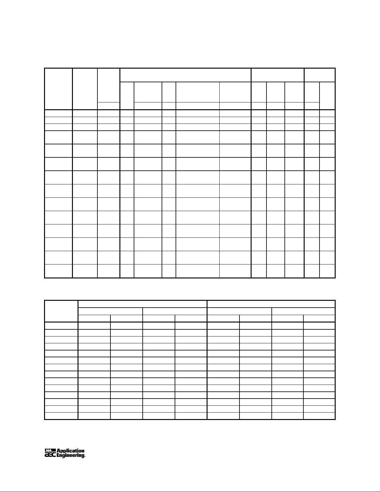
Figure 1
ACOA Specifications
Model
number Circuits Lbs. Qty cfm qts. % watts in. in. in. qty. kW
ACOA15 1 30 1 35.3 4.5 0, 50, 100 65 5 60 1 5/8 2 2.0
ACOA20 1 50 1 60.1 4.1 0, 50, 100 100 6 60 3 2 2.7
ACOA25 1 50 1 60.1 4.4 0, HGP, 50, 100 100 7 60 3 2 2.7
ACOA30 1 60 1 75.5 5
ACOA35 1 60 1 90.1 7.5
ACOA45 2 90 2 100.6 8.5
ACOA55 2 110 1 135.5 9.8
ACOA70 2 140 2 180.2 15
ACOA80 2 150 2 214.3 16.2
ACOA90 3 180 3 226.5 15
ACOA100 3 180 3 270.2 22.5
ACOA110 4 210 4 271 19.5
ACOA125 4 225 4 360 30
ACOA135 4 225 4 360 30
refrig-
Total
erant
charge
Displace-
ment
Compressor(s)
Steps of
Oil
chg
capacity
reduction
0, HGB, 30,
67, 100
0, HGB, 30,
67, 100
0, HGB, 25,
50,75, 100
0, HGB, 21,
42, 78, 100
0, HGB, 34,
50, 84, 100
0, HGB, 25,
50, 75, 100
0, HGB, 22, 33,
56, 67, 89, 100
0, HGB, 22, 33,
56, 67, 89, 100
0, HGB, 21,
42, 71, 100
0, HGB, 25,
50, 75, 100
0, HGB, 25,
50, 75, 100
Evaporator
Crankcase
heater
200 7 60 3 3 4.4
200 8 60 3 3 4.4
200 10 60 4 4 5.4
300 11 60 4 5 7.1
400 12 60 4 6 10.2
400 13 60 4 8 13.6
600 12 102 4 9 15.3
600 14 92 4 9 15.3
600 14 102 5 10 17
800 14 102 5 12 20.4
800 16 122 6 12 20.4
Shell
dia.
Tube
length
Conn.
size
Air-cooled
condenser
Fans
Total
Cooling Capacity, Unit Weights
Cooling capacity Weights
Model 100% water 50% H2O, 50% glycol Shipping weight Operating weight
no. tons Kcal/hr. tons Kcal/hr. lbs. kg lbs. kg
ACOA15 14.7 44,453 14.1 42,683 1,835 834 1,865 847
ACOA20 19.0 57,456 18.1 54,734 1,967 894 2,017 916
ACOA25 24.9 75,298 23.9 72,274 2,158 980 2,208 1,003
ACOA30 32.7 98,885 31.0 93,744 2,687 1,220 2,747 1,248
ACOA35 36.4 110,074 34.8 105,235 2,835 1,288 2,895 1,315
ACOA45 43.1 130,334 41.5 125,496 3,939 1,789 4,029 1,830
ACOA55 57.4 173,578 54.9 166,018 4,631 2,106 4,741 2,153
ACOA70 71.9 217,426 69.1 208,958 5,252 2,385 5,392 2,444
ACOA80 87.0 263,088 83.3 251,899 6,998 3,173 7,138 3,241
ACOA90 98.0 296,352 95.3 288,187 8,220 3,732 8,437 3,831
ACOA100 107.6 325,382 102.1 308,750 8,582 3,897 8,807 3,999
ACOA110 115.0 347,760 107.9 326,290 9,397 4,267 9,647 4,380
ACOA125 131.0 396,144 120.9 365,602 10,160 4,613 10,410 4,727
ACOA135 147.1 444,830 142.1 429,710 11,087 5,034 11,472 5,209
Based on 60ºF (16ºC) return from process, 50ºF (10ºC) chilled water supply temperature, and 95ºF (35ºC)
ambient. Consult factory for requirements below 40ºF (4ºC).
fan
ACOA Series Air-Cooled Central Chillers Page 9
Page 11
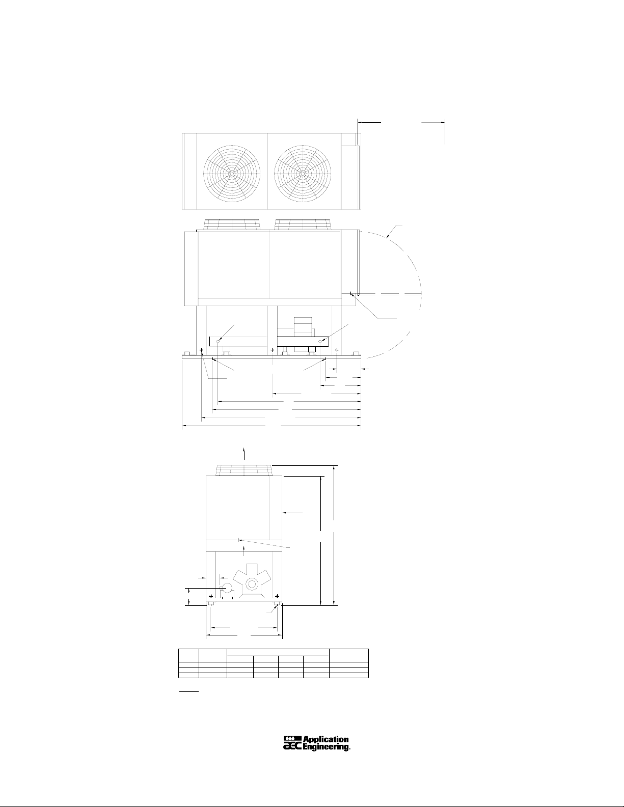
Figure 2
ACOA15, ACOA20, and ACOA25 Outline Drawing
ALLOW 60" FOR
SERVICE ACCESS
DOOR SWING
WATER
OUT
MOUNTING LOCATIONS
LIFTING
HOLE
90-3/16"
101"
50-3/16"
B
84"
AIR FLOW
CONTROL
BOX
AIR FLOW
`D'
`C'
MOUNTING
LOCATION
37-5/16
43"
MODEL
MODEL
ACOA
EVAP.
15
CHS00560
CHS00660
CHS00760
23-3/16" 80-13/16"
23-15/16"
20
25
NOTES:
1 - ALL DIMENSIONS IN INCHES.
2 - VENT AND DRAIN CONNECTIONS PROVIDED ON COOLER.
3 - ALLOW 60" CLEARANCE AT CONTROL PANEL END OF UNIT FOR SERVICE
4 - USE MINIMUM 36" FLEXIBLE CONDUIT TO CONTROL BOX TO ISOLATE UNIT.
5 - WATER PIPING TO BE SUPPORTED TO MINIMIZE LOAD ON UNIT.
6 - ALL DIMENSIONS AND SPECIFICATIONS ARE SUBJECT TO CHANGE WITHOUT
NOTICE.
DIMENSIONS
'A'
80"
24"
80-1/16"
AIR
FLOW
POWER
ENTRY
'B'
'C'
5-1/16"
9-3/4"
5-7/16"
10-3/16"
2-3/4"
10-15/16"
73"
'D'
WATER
20"
A
79"
WATER
CONNECTION
1-1/2" N.P.T.
3" N.P.T.
3" N.P.T.
POWER ENTRY
IN
(SEE NOTE 4)
13-13/16"
Page 10
ACOA Series Air-Cooled Central Chillers
Page 12

Figure 3
ACOA30 and ACOA35 Outline Drawing
ALLOW 60" FOR
SERVICE ACCESS
DOOR SWING
LIFTING
HOLE
WATER
OUT
MOUNTING LOCATIONS
120"
130-3/16"
141"
90-3/16"
WATER
IN
20"
A
50-3/16"
70"
B
13-13/16"
POWER ENTRY
(SEE NOTE 4)
AIR FLOW
CONTROL
BOX
AIR FLOW
`D'
`C'
MOUNTING
LOCATION
37-5/16"
43"
AIR
FLOW
POWER
ENTRY
79"
73"
MODEL
MODEL
ACOA
EVAP
30 CHS00760
ACOA Series Air-Cooled Central Chillers Page 11
23-15/16" 80-1/16"
25-1/4" 78-3/4" 11-1/2"
CHS0086035
NOTES:
1 - ALL DIMENSIONS IN INCHES.
2 - VENT AND DRAIN CONNECTIONS PROVIDED ON COOLER.
3 - ALLOW 60" CLEARANCE AT CONTROL PANEL END OF UNIT FOR SERVICE
4 - USE MINIMUM 36" FLEXIBLE CONDUIT TO CONTROL BOX TO ISOLATE UNIT.
5 - WATER PIPING TO BE SUPPORTED TO MINIMIZE LOAD ON UNIT.
6 - ALL DIMENSIONS AND SPECIFICATIONS ARE SUBJECT TO CHANGE WITHOUT NOTICE
DIMENSIONS
'C'
B'
`A'
10-15/16"
2-3/4"
1-5/8"
'D'
WATER
CONNECTION
3" N.P.T.
3" N.P.T.
Page 13
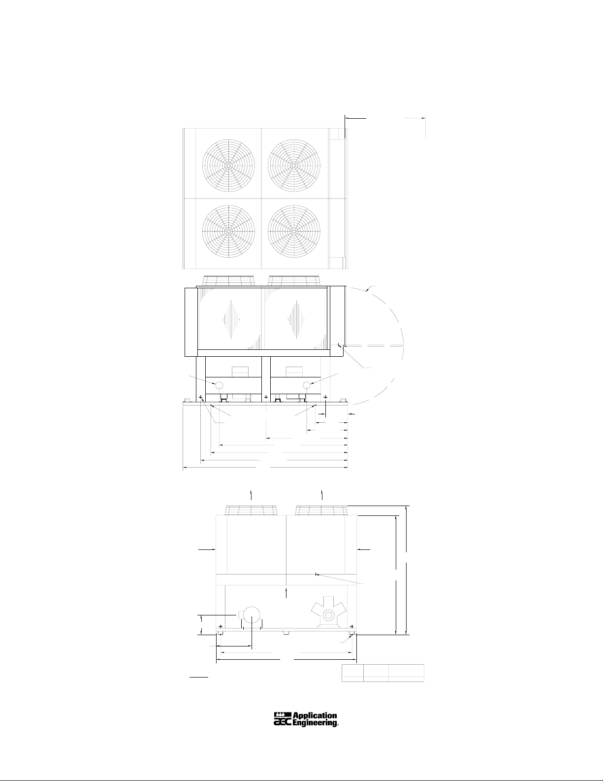
Figure 4
ACOA45 Outline Drawing
ALLOW 60" FOR
SERVICE ACCESS
DOOR SWING
WATER
OUT IN
MOUNTING LOCATIONS
LIFTING
HOLES
50-3/16"
78-3/4"
84"
90-3/16"
101"
AIR
FLOW
12-1/16"
4-11/16"
NOTES:
1 - ALL DIMENSIONS IN INCHES.
2 - VENT AND DRAIN CONNECTIONS PROVIDED ON COOLER.
3 - ALLOW 60" CLEARANCE AT CONTROL PANEL END OF UNIT FOR SERVICE
4 - USE MINIMUM 36" FLEXIBLE CONDUIT TO CONTROL BOX TO ISOLATE UNIT.
5 - WATER PIPING TO BE SUPPORTED TO MINIMIZE LOAD ON UNIT.
6 - ALL DIMENSIONS AND SPECIFICATIONS ARE SUBJECT TO CHANGE WITHOUT NOTICE
CONTROL
BOX
AIR FLOW
MOUNTING LOCATIONS
80-5/16"
86"
25-1/4"
AIR FLOWAIR FLOW
CONTROL
BOX
20"
WATER
MODEL
ACOA
45
13-13/16"
AIR
FLOW
POWER
ENTRY
CHD01060
POWER ENTRY
(SEE NOTE 4)
MODEL
EVAP.
79"
73"
WATER
CONNECTION
4" N.P.T.
Page 12
ACOA Series Air-Cooled Central Chillers
Page 14
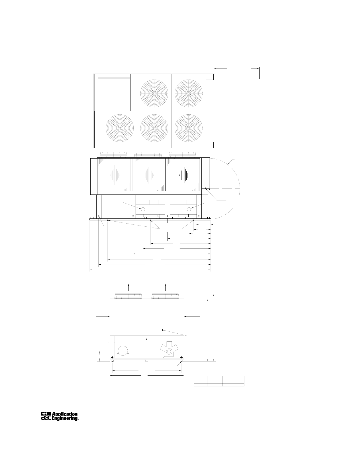
Figure 5
ACOA55 Outline Drawing
ALLOW 60" FOR
SERVICE ACCESS
DOOR SWING
FLOW
3-9/16"
12-5/8"
AIR
WATER
OUT
LIFTING
HOLES
CONTROL
BOX
130-3/16"
141"
AIR FLOW
120"
AIR FLOWAIR FLOW
CONTROL
MOUNTING
LOCATIONS
78-3/4"
90-3/16"
BOX
13-13/16"
POWER ENTRY
(SEE NOTE 4)
WATER
IN
20"
25-1/4"
50-3/16"
70"
AIR
FLOW
POWER
ENTRY
79"
73"
MOUNTING LOCATION
80-5/16"
86"
NOTES:
1 - ALL DIMENSIONS IN INCHES.
2 - VENT AND DRAIN CONNECTIONS PROVIDED ON COOLER.
3 - ALLOW 60" CLEARANCE AT CONTROL PANEL END OF UNIT FOR SERVICE
4 - USE MINIMUM 36" FLEXIBLE CONDUIT TO CONTROL BOX TO ISOLATE UNIT.
5 - WATER PIPING TO BE SUPPORTED TO MINIMIZE LOAD ON UNIT.
6 - ALL DIMENSIONS AND SPECIFICATIONS ARE SUBJECT TO CHANGE WITHOUT NOTICE
ACOA Series Air-Cooled Central Chillers Page 13
MODEL
MODEL
EVAP.
ACOA
55 CHD01160 4" N.P.T.
WATER
CONNECTION
Page 15

Figure 6
ACOA70 Outline Drawing
AIR FLOW
AIR FLOW
ALLOW 60" FOR
SERVICE ACCESS
DOOR SWING
2-5/16"
13-3/16"
WATER
LIFTING
HOLES
OUT
CONTROL
BOX
POWER ENTRY
MOUNTING LOCATIONS
120"
130-3/16"
141"
AIR FLOW
CONTROL
BOX
AIR FLOW
MOUNTING LOCATION
80-5/16"
86"
90-3/16"
78-3/4"
13-13/16"
WATER
CONNECTION
4" N.P.T.
POWER ENTRY
(SEE NOTE 4)
WATER
IN
20"
25-1/4"
50-3/16"
70"
79"
73"
MODEL
MODEL
EVAP.
ACOA
CHD01260
70
Page 14
NOTES:
1 - ALL DIMENSIONS IN INCHES.
2 - VENT AND DRAIN CONNECTIONS PROVIDED ON COOLER.
3 - ALLOW 60" CLEARANCE AT CONTROL PANEL END OF UNIT FOR SERVICE.
4 - USE MINIMUM 36" FLEXIBLE CONDUIT TO CONTROL BOX TO ISOLATE UNIT.
5 - WATER PIPING TO BE SUPPORTED TO MINIMIZE LOAD ON UNIT.
6 - ALL DIMENSIONS AND SPECIFICATIONS ARE SUBJECT TO CHANGE WITHOUT NOTICE
ACOA Series Air-Cooled Central Chillers
Page 16
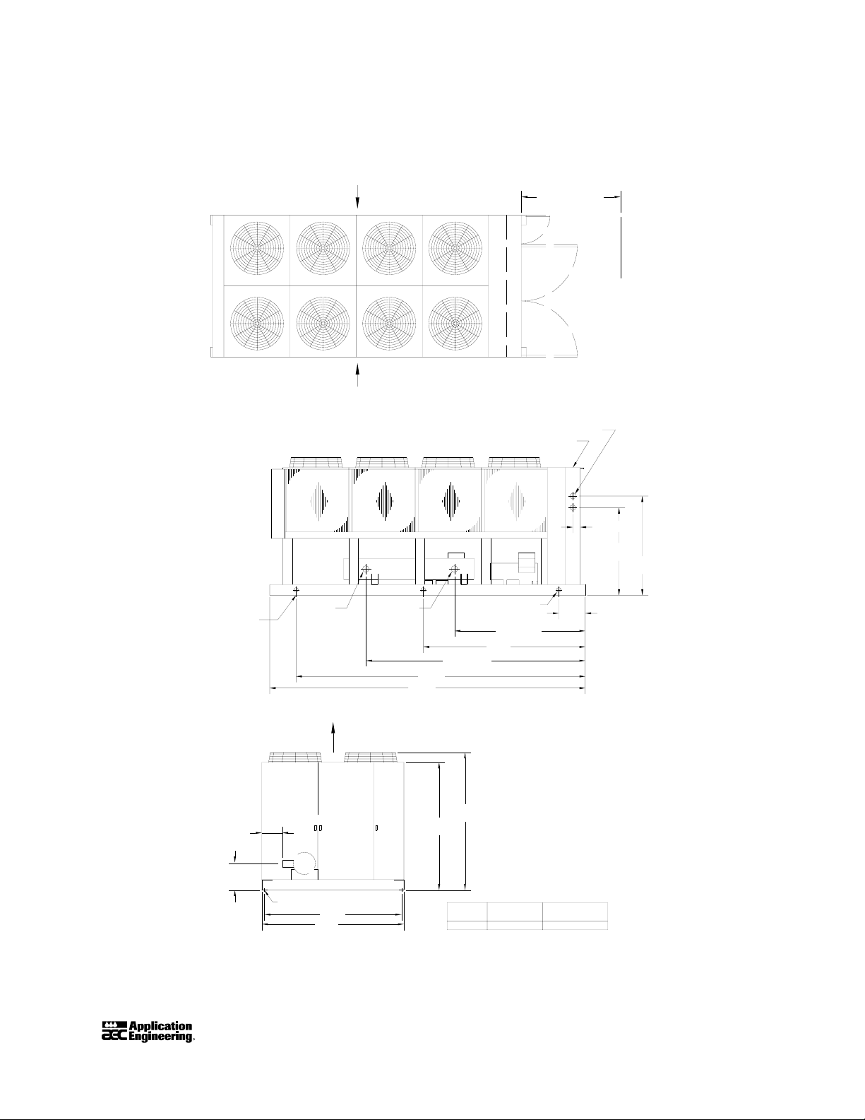
Figure 7
ACOA80 Outline Drawing
AIR FLOW
SIDE & BOTTOM
AIR FLOW
SIDE & BOTTOM
ALLOW 60" FOR
SERVICE ACCESS
MOUNTING
LOCATION
12-3/8"
WATER WATER IN
OUT
AIR FLOW
CONTROL BOX
POWER ENTRY (SEE NOTE #4)
132-3/4"
175"
191"
83-3/8"
77-3/8"
CONTROL BOX
LIFTING HOLE
79-1/4"
98"
4-1/2"
52-5/8"
59-5/8"
16"
16-1/8"
MOUNTING LOCATION
NOTE:
1 - ALL DIMENSIONS IN INCHES.
2 - VENT AND DRAIN CONNECTIONS PROVIDED ON COOLER.
3 - ALLOW 60" CLEARANCE AT CONTROL PANEL END OF UNIT FOR SERVICE.
4 - USE MINIMUM 36" FLEXIBLE CONDUIT TO CONTROL BOX TO ISOLATE UNIT.
5 - WATER PIPING TO BE SUPPORTED TO MINIMIZE LOAD ON UNIT.
6 - ALL DIMENSIONS AND SPECIFICATIONS ARE SUBJECT TO CHANGE WITHOUT NOTICE
ACOA Series Air-Cooled Central Chillers Page 15
83"
86"
MODEL
ACOA
80
MODEL
EVAP.
CHD01360 4" NPT
WATER
CONNECTION
Page 17
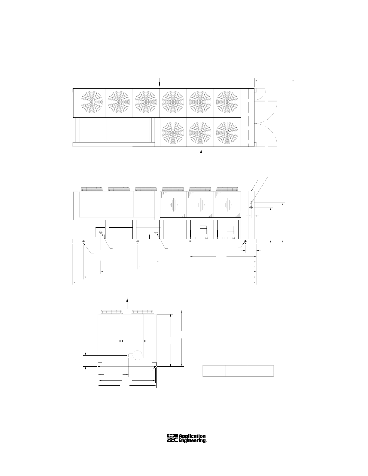
Figure 8
ACOA90 and ACOA100 Outline Drawing
AIR FLOW
SIDE & BOTTOM
AIR FLOW
SIDE & BOTTOM
ALLOW 60" FOR
SERVICE ACCESS
WATER OUT WATER IN
MOUNTING
LOCATION
AIR FLOW
CONTROL BOX
271"
255"
77-3/8"
229-3/16"
83-3/8"
POWER ENTRY (SEE NOTE #4)
148-3/16"
175"
CONTROL BOX
LIFTING HOLE
98"
4-1/2"
52-5/8"
59-5/8"
16"
Page 16
16-3/8"
MODEL
MOUNTING
86"
LOCATION
83"
45-7/16"
NOTES:
1 - ALL DIMENSIONS IN INCHES.
2 - VENT AND DRAIN CONNECTIONS PROVIDED ON COOLER.
3 - ALLOW 60" CLEARANCE AT CONTROL PANEL END OF UNIT FOR SERVICE.
4 - USE MINIMUM 36" FLEXIBLE CONDUIT TO CONTROL BOX TO ISOLATE UNIT.
5 - WATER PIPING TO BE SUPPORTED TO MINIMIZE LOAD ON UNIT.
6 - ALL DIMENSIONS AND SPECIFICATIONS ARE SUBJECT TO CHANGE WITHOUT NOTICE
ACO
090 & 100
ACOA Series Air-Cooled Central Chillers
EXT14092
MODEL
EVAP.
WATER
CONNECTION
5" VICTAULIC
Page 18

Figure 9
ACOA110 Outline Drawing
AIR FLOW
SIDE & BOTTOM
AIR FLOW
SIDE & BOTTOM
ALLOW 60" FOR
SERVICE ACCESS
WATER OUT WATER IN
MOUNTING
LOCATION
238-3/8"
255"
271"
AIR FLOW
CONTROL BOX
83-3/8"
77-3/8"
POWER ENTRY (SEE NOTE #4)
LIFTING HOLE
147-3/4"
175"
CONTROL BOX
4-1/2"
52-5/8"
59-5/8"
16"
98"
16-3/8"
MOUNTING LOCATION
45-7/16"
83"
86"
NOTE:
1 - ALL DIMENSIONS IN INCHES.
2 - VENT AND DRAIN CONNECTION PROVIDED ON COOLER.
3 - ALLOW 60" CLEARANCE AT CONTROL PANEL END OF UNIT FOR SERVICE.
4 - USE MINIMUM 36" FLEXIBLE CONDUIT TO CONTROL BOX TO ISOLATE UNIT.
5 - WATER PIPING TO BE SUPPORTED TO MINIMIZE LOAD ON UNIT.
6 - ALL DIMENSIONS AND SPECIFICATIONS ARE SUBJECT TO CHANGE WITHOUT NOTICE
ACOA Series Air-Cooled Central Chillers Page 17
MODEL
ACO EVAP.
110
MODEL
EXF14102
WATER
CONNECTION
5" VICTAULIC
Page 19

Figure 10
ACOA125 and ACOA135 Outline Drawing
AIR FLOW
SIDE & BOTTOM
AIR FLOW
SIDE & BOTTOM
ALLOW 60" FOR
SERVICE ACCESS
WATER OUT WATER IN
MOUNTING
LOCATION
AIR FLOW
271"
255"
POWER ENTRY (SEE NOTE #4)
175"
B
CONTROL BOX
LIFTING HOLE
98"
A
4-1/2"
52-5/8"
59-5/8"
16"
C
Page 18
CONTROL BOX
D
83"
86"
MOUNTING
LOCATION
77-3/8"
83-3/8"
NOTES:
1 - ALL DIMENSIONS IN INCHES.
2 - VENT AND DRAIN CONNECTIONS PROVIDED ON COOLER.
3 - ALLOW 60" CLEARANCE AT CONTROL PANEL END OF UNIT FOR SERVICE.
4 - USE MINIMUM 36" FLEXIBLE CONDUIT TO CONTROL BOX TO ISOLATE UNIT.
5 - WATER PIPING TO BE SUPPORTED TO MINIMIZE LOAD ON UNIT.
6 - ALL DIMENSIONS AND SPECIFICATIONS ARE SUBJECT TO CHANGE WITHOUT NOTICE
MODEL
MODEL
ACO
EVAP.
EXF14102 147-3/4" 238-3/8"
125
DIMENSIONS
A
ACOA Series Air-Cooled Central Chillers
B
C
16-3/8"D25-3/4"
WATER
CONNECTION
5" VICTAULIC
6" VICTAULIC27-7/8"17-3/8"241-13/16"132-1/16"EXF16122135
Page 20

2 Shipping Information
2-1 Unpacking and Inspection
You should inspect your AEC/Application Automation ACOA Series air-cooled central chiller
for possible shipping damage. If the container and packing materials are in re-usable condition,
save them for reshipment if necessary.
Thoroughly check the equipment for any damage that might have occurred in transit, such as
broken or loose wiring and components, loose hardware and mounting screws, etc. In case of
breakage, damage, shortage, or incorrect shipment, refer to the following sections.
2-2 In the Event of Shipping Damages
Important!
According to the contract terms and conditions of the Carrier,
the responsibility of the Shipper ends at the time and place of shipment.
The Carrier then assumes full responsibility of the shipment.
Notify the transportation company’s local agent if you discover damage.
Hold the damaged goods and packing material for the examining agent’s inspection. Do not
return any goods to AEC, Inc. before the transportation company inspection and
authorization.
File a claim against the transportation company. Substantiate the claim by referring to the
agent’s report. A certified copy of our invoice is available upon request. The original Bill of
Lading is attached to our original invoice. If the shipment was prepaid, write us for a
receipted transportation bill.
Advise AEC, Inc. regarding your wish for replacement and to obtain an RMA (return
material authorization) number.
2-3 If the Shipment is Not Complete
Check the packing list. The apparent shortage may be intentional. Back-ordered items are noted
on the packing list.
ACOA Series Air-Cooled Central Chillers Page 19
Page 21

You should have:
ACOA Series central chiller.
Bill of Lading.
Packing list.
Operating and Installation packet.
Electrical schematic and panel layout drawings.
Component instruction manuals.
Re-inspect the container and packing material to see if you missed any smaller items during
unpacking. Determine that the item was not inadvertently taken from the area before you
checked in the shipment. Notify AEC, Inc. immediately of the shortage.
2-4 If the Shipment is Not Correct
If the shipment is not what you ordered, contact AEC, Inc. immediately. Include the order
number and item. Hold the items until you receive shipping instructions.
2-5 Returns
Important!
Do not return any damaged or incorrect items
until you receive shipping instructions from AEC, Inc.
2-6 Uncrating Your Chiller
Caution!
Due to the size and weight of ACOA chillers,
AEC, Inc. recommends using bonded professional millwrights
to unload and move ACOA chillers.
Rig the chiller from the frame only and use spreader bars to prevent load transfer to any chiller
components. Rig the frame from at least four points and balance the load before lifting to clear
the skid.
Page 20
ACOA Series Air-Cooled Central Chillers
Page 22

3 Installation
3-1 Installation Location Considerations
• Consult a structural engineer to assure that the floor, mounting pad, or structural steel
support is of adequate strength.
• Provide a level foundation for proper operation.
• Put the air-cooled condenser(s) where plenty of ambient air can flow to the condenser and
can also remove the heated air from the area.
• Keep the condenser away from steam, hot air, or fume exhausts.
• Put chiller/condensers where sound levels and vibration can not be a problem.
• Support the chiller/condenser to avoid vibration and noise transmission into the building.
• ACOA chiller/condensers feature rubber shear vibration isolators.
• Mount rooftop condensers over corridors, utility areas, rest rooms, etc., or consult with
sound/structural specialists on critical installations.
• Locate the unit close to your process to reduce piping expense.
• Locate the unit adjacent to drain and city water sources.
• Allow sufficient space for maintenance and easy access to all components.
3-2 Process Water Piping Considerations
• Constant process water flow through the evaporator is critical for proper operation.
• Minimum external pressure drop is critical for proper operation.
• Run all properly-sized external chilled water connections for the process.
• Provide the largest possible openings and passages for the flow of chilled water through
platens, dies, molds, or other pieces of equipment.
• If process piping is exposed to temperatures below 32ºF (0ºC), use heater tape and/or
insulation to protect it from freezing. Main power is required to keep the tape, sump
heaters, and evaporator heaters on. Addition of anti-freeze is highly recommended for this
unit(s).
• Install water pressure gages before and after the evaporator (if not factory installed) to
make sure water pressure and flow rate are constant.
ACOA Series Air-Cooled Central Chillers Page 21
Page 23

3-3 Galvanic Corrosion Considerations
Water circuit piping components are primarily ferrous (iron) and react electro-chemically with
non-ferrous metallic materials such as copper. Some water has dissolved minerals that greatly
accelerate the reaction between dissimilar metals.
Use PVC or ferrous piping to reduce galvanic action. If piping must be copper, use dielectric
unions at the chiller.
3-4 Water Treatment Considerations
Water treatment is important in any piping system. In some locations, raw water can be used in
the system without problem; in other locations, it may result in large deposits of scale and
corrosion. Water that is corrosive, high in mineral content, or contains entrained solids can
reduce chiller efficiency and destroy evaporators.
AEC, Inc. offers a complete line of water treatment equipment. Contact your AEC, Inc. Sales
Representative for water testing and treatment options.
3-5 Making Process Water Connections
ACOA chillers have two chilled water connections per circuit:
TO PROCESS
The
TO PROCESS water connection is the chilled water supply outlet (located closest to the
expansion valve) leading to the process being controlled.
FROM PROCESS
The
FROM PROCESS water connection is the chilled water return inlet for water returning back
to the chiller from the process to be cooled and recirculated.
3-6 ACOA Refrigerant Charge Considerations
ACOA chillers are charged at the factory with the refrigerant for which they were designed. The
type and amount is listed on the serial tag.
Page 22
ACOA Series Air-Cooled Central Chillers
Page 24

3-7 Making Electrical Connections
Check the serial tag voltage and amperage requirements and make sure your electrical service
conforms.
Bring properly-sized power leads and ground from a fused disconnect (installed by your
electrician) to the unit. Use fuses in the disconnect switch, sized according to the National
Electrical Code recommendations listed on the electrical schematic in the control enclosure.
Caution!
Electrical connections must comply with all applicable electrical codes.
The chiller must be grounded in accordance with NEC Article 250.
Voltage must be within plus or minus ten percent (±10%) of the nameplate
rating.
Phase imbalance must be less than two percent (2%) in accordance with
NEMA MG1-14.32.
ACOA chillers must have properly sized disconnects conforming with all
local codes.
Check all wiring for damage and all terminal connections for tightness.
Shipping can loosen connections.
Use copper conductors when connecting to the ACOA terminal blocks.
3-8 Checking Motor Rotation Direction
Compressor
The compressor(s) operate(s) properly in either direction.
Condenser Fan
The condenser fan draws air through the condenser and discharges it up from the condenser.
To change fan rotation direction:
1. Disconnect and lock out power at the fused disconnect.
2. If all fans are going backwards, reverse any two main power leads.
3. If only some of the fans are going backwards, switch any two of the respective motor
leads.
ACOA Series Air-Cooled Central Chillers Page 23
Page 25

- Notes -
Page 24
ACOA Series Air-Cooled Central Chillers
Page 26

4 Sequence of Operation
4-1 General Information
The operating thermostat (opstat) labeled 4TAS monitors return chilled water/air temperature
and activates various steps of capacity control to maintain controlled leaving chilled water
temperature or return air temperature.
Each model has similar control logic. Refer to your wiring diagram located on the inside control
panel door for your control layout for more information.
4-2 Circuit Operation
Typical 2 compressor control sequence of operation 4 step capacity control, continuous
pumpdown. Refer to the typical wiring diagrams.
1. Unit on Standby
• Main field disconnect switch closed
• 115 VAC control power on
•
S1 control switch on
•
4TAS-1 through 4TAS-4 opstat contacts open or customer control contacts open
•
2TAS freezestat closed
• FLS flow switch closed
•
CWP chiller pump auxiliary contacts closed
• Water flow rates nominal
• Compressor control switches closed
• All safety switches closed
• Pumpdown during standby
Any one of the compressors may come on for a short time and pump down if any low side
pressure buildup occurs during the standby period. The 1TR cycle timer locks out for five (5)
minutes after a pumpdown before the compressor can restart. Pumpdowns can be expected
immediately following a normal
the
4PS pumpdown switch to close momentarily.
ON cycle as residual liquid in the low side vaporizes, causing
ACOA Series Air-Cooled Central Chillers Page 25
Page 27

2. Run Cycle Sequence (Increasing Load)
• Customer contacts close
Step 1
1. Opstat
bypasses pumpdown switch
4TAS-1 closes as return chilled water temperature starts to rise. Relay 8CR
4PS-1 to remove it from the control circuit.
Note: Go to Step 4 if Compressor 1 is off for more than five (5) minutes.
2. Cycle timer
1TR times out and closes (up to a five (5) minute delay).
3. Compressor 1 starts. Contactor auxiliary switch energizes liquid line solenoid 1SOL and
Circuit 1 refrigerant flow starts. Compressor 1 unload solenoid
4TAS-NC2 and NC4. Compressor 1 unloads one bank of cylinders.
3SOL energizes through
4. Oil failure switch 3PS-1 starts to time open (120 sec. delay). Low pressure switch 9PS-1
starts to time open (120 to 240 sec. delay).
Note: If oil pressure or suction pressure is not established at a normal level within the above-
listed delay times, Circuit 1 shuts down.
5. Circuit 1 oil and suction pressure rise to normal levels, and
3PS-1 and 9PS-1 terminate
the time open sequence.
First stage capacity is now on line.
Step 2
6. Opstat 4TAS-2 closes as water temperature continues to rise. Compressor 1 unload
solenoid
1SOL de-energizes as 4TAS-NC2 opens. Compressor 1 loads up to 100%.
Second stage capacity is now on line.
Step 3
7. Opstat 4TAS-3 closes as water temperature continues to rise. Relay 9CR bypasses
pumpdown switch
4PS-2 to remove it from the control circuit. Staging timer 4TR-2
delays Compressor 2 start (10 to 30 seconds).
8. Staging timer
loaded. Contactor auxiliary switch energizes liquid line solenoid
refrigerant flow starts. Oil Failure switch
pressure switch
4TR-2 closes. If cycle timer 1TR-2 times out, Compressor 2 starts 100%
2SOL and circuit 2
3PS-2 starts to time open (120 sec. delay). Low
9PS-2 starts to time open (120 to 240 sec. delay).
Note: If oil pressure or suction pressure is not established at a normal level within previously-
listed delay times, Circuit 2 shuts down.
Page 26
ACOA Series Air-Cooled Central Chillers
Page 28

9. Compressor 1 unload solenoid 3SOL re-energizes through 4TAS-2 and 4.
10. Compressor 1 unloads one bank of cylinders.
11. Circuit 2 oil and suction pressures rise to normal levels, and
3PS-2 and 9PS-2 terminate
the time open sequence.
Third stage capacity is now on line.
Step 4
12. Opstat 4TAS-4 closes as water temperature continues to rise. Compressor 1 unload
solenoid
3SOL de-energizes by 4TAS-NC4 open. Compressor 1 loads to 100%.
13. 100% unit capacity is not on line.
Run Cycle Sequence (Decreasing Load)
Step 4
1. Opstat 4TAS-4 opens as leaving water temperature starts to drop. Compressor 1 unload
solenoid
2. Compressor 1 unloads one bank of cylinders.
Third stage capacity is now on line (Compressor 1 at part load; Compressor 2 at 100%).
Step 3
3SOL energizes through 4TAS-NC4 closed and N02 closed.
1. Opstat 4TAS-3 opens as water temperature continues to drop. Relay 9CR de-energizes,
removing
de-energizes through
solenoid
2. When suction pressure drops to the pumpdown limit,
4PS-2 bypass (4PS-2 now controls pumpdown). Compressor 1 unload solenoid
4TAS-N02 open. Compressor 1 loads back up to 100%. Liquid line
2SOL de-energizes and Circuit 2 refrigerant flow stops.
4PS-2 opens and Compressor 2
stops. Circuit 2 pumpdown and off sequence is now complete, and all Circuit 2 controls
are back to standby status.
Second stage capacity is now on line (Compressor 1 at 100%).
Step 2
3. Opstat 4TAS-2 opens as water temperature continues to drop. Compressor 1 unload
solenoid
3SOL is energized through 4TAS-NC2 and NC4 closed. Compressor 1 unloads
one bank of cylinders.
First stage capacity is now on-line.
ACOA Series Air-Cooled Central Chillers Page 27
Page 29

Step 1
4. Opstat
solenoid
energizes, removing
4TAS-1 opens as water temperature reaches minimum set point. Liquid line
1SOL de-energizes and Circuit 1 refrigerant flow stops. Relay 8CR de-
4PS-1 bypass (4PS-1 now controls pumpdown). Compressor 1
remains running and Circuit 1 pumpdown begins.
5. When suction pressure drops to the pumpdown limit,
4PS-1 opens and Compressor 1
stops. Circuit 1 pumpdown and unload sequence is now complete, and all Circuit 1
controls are back to standby status.
Figure 11
ACOA Control Settings and Set Points (Unit is Off)
ACOA Control Settings
Time Delay
1TR-1 & 2 5 Min.
3PS-1 & 2 120 Sec.
9PS-1 & 2 120 Sec.
4TR-2 10 Sec.
5TR-1 & 2 2 Min.
Pressure (PSIG) Open Close
1PS-1 & 2 360
10, 11PS-1 140 190
10, 11PS-2 160 21-0
10, 11PS-3 170 230
Temperature Open Close
4TAS-1 LWT + .40R LWT + .55R
4TAS-2 LWT + .55R LWT + .70R
4TAS-3 LWT + .70R LWT + .85R
4TAS-4 LWT + .85R LWT + R
Percentage
of ethylene
glycol ºF ºC psig kPa psig kPa psig kPa ºF ºC
0% 32ºF 0ºC 55 psig 379 kPa 45 psig 310 kPa 70 psig 483 kPa 38ºF 3ºC
10% 27ºF -3ºC 49 psig 338 kPa 39 psig 269 kPa 64 psig 441 kPa 33ºF 1ºC
20% 18ºF -8ºC 39 psig 269 kPa 29 psig 200 kPa 54 psig 372 kPa 24ºF -4ºC
30% 3ºF -16ºC 33 psig 228 kPa 23 psig 159 kPa 48 psig 331 kPa 9ºF -13ºC
40% -13ºF -25ºC 33 psig 228 kPa 23 psig 159 kPa 48 psig 331 kPa -7ºF -22ºC
50% -20ºF -29ºC 33 psig 228 kPa 23 psig 159 kPa 48 psig 331 kPa -14ºF -26ºC
3TAS 40ºF 43ºF
ACOA Set Points
Minimum
ambient
Minimum
9PS open
4PS
open
4PS
close
Minimum
2TAS open
Caution!
Do not set 9PS, 4PS, or 2TAS lower than indicated for your glycol concentration—
the AEC, Inc. warranty is voided! The AEC, Inc. warranty does not cover freeze-up!
Figure 12
Page 28
ACOA Series Air-Cooled Central Chillers
Page 30

*
UNIT
FUSING
1TB
L1
L2
L3
SEE
NOTE 9
1M1
GND
CONTROL CIRCUIT 115/1/60
(CONTROL POWER)
Typical ACOA Wiring Diagram
200-230V/3/60
SEE NOTES 2, 3 & 4
321
3L1 3L3
3FM
15A
7M 4M
1MTR
COMPRESSOR MOTORS
SEE NOTE 5
(SEE NOTE 7)
2M1
2MTR
SEE BORDER
DGM. FOR
VAR. SPEED
OPTION
FUSE NO.
2M21M2
3M 5M
70 71 72 76 77 78
1FM
1M1-1
2M1-1
848382
5FM
FAN MOTORS
1HTR
2HTR
73 74 75
2FM
2
65
4
15A
4L1 4L3
8M6M
79 80 81
4FM
COMP NO. 1 OIL HEATER
COMP NO. 2 OIL HEATER
878685
6FM
5
8
J27
2UVR S3
8
J28
8
JJ
899
27
COMP
28
COMP
98 99
S21UVR
#1
18
#2
34
9
10 11
1TAS-1
SEE NOTE 8
MOTOR TEMP
SENSORS
1PS-2 3PS-2
1TAS-2
SEE NOTE 8
MOTOR TEMP
SENSORS
24H 24G
C1
C2
C3 NO3
+6.2
9PS-1
3PS-1
T1 M1 T2M2
S1
50 51 52 53
9PS-2
2019
S1
82
115VAC
24VAC
29 33
STEP 1
STEP 2
STEP 3
STEP 4
4TAS
12
S2S3C
21
S2
2T
NO1
NC1
NO2
NC2
NC3
NO4C4
NC4
ISA
8CR
13
4PS-1
BLK
9CR
22
4PS-2
M2 T2M1T1
C
S3
BLK
57565554
31
1TR-1
14
12
4
4CR-1
4TR-2
23
31
5CR-1
35
38
58
15
J15
15
59
24
25
J25
25
1M1-2
32
2M1-2
36
9CR
48
4CR
COMP NO. 1 START RELAY (10, 43)
COMP NO. 1 5 MIN. ANTI-CYCLE
TIMER
COMP NO. 1 CONTACTOR (1, 28)
1M2
HTR
HTR
5CR
2M1
2M2
HTR
HTR
1SOL
8CR
2SOL
9CR
3SOL
COMP NO. 1 CONTACTOR
COMP NO. 1 OIL FAIL
COMP NO. 1 LOW PRESSURE
COMP NO. 1 MOTOR TEMP
COMP NO. 2 START RELAY (19, 46)
COMP NO. 2 5 MIN. ANTI-CYCLE
TIMER
COMP NO. 2 CONTACTOR (2, 33)
COMP NO. 2 CONTACTOR
COMP NO. 2 OIL FAIL
COMP NO. 2 LOW PRESSURE
COMP NO. 2 MOTOR TEMP
COMP NO. 1 LIQ LINE SOLENOID
COMP NO. 1 LOCKIN RELAY (6)
COMP NO. 2 LIQ LINE SOLENOID
COMP NO. 2 LOCKIN RELAY (15, 37)
COMP NO. 1 UNLOAD SOLENOID
3PS-1
9PS-1
16
3PS-2
9PS-2
26
31
4CR-2
39
5CR-2
43
Typical schematic - See the drawings
provided with your ACOA chiller
ACOA Series Air-Cooled Central Chillers Page 29
10PS-1
11PS-1
CIRC 1
CIRC 2
40
10PS-2
CIRC 1
44
11PS-2
CIRC 2
41
42
10PS-3
CIRC 1
45
46
11PS-3
CIRC 2
5TB
3M
CONTACTOR-FAN 1
5M
CONTACTOR-FAN 3
7M
CONTACTOR-FAN 5
4M
CONTACTOR-FAN 2
6M
CONTACTOR-FAN 4
8M
CONTACTOR-FAN 6
CUSTOMER SUPPLIED 115VAC
POWER. MAXIMUM FUSE SIZE 15A.
102
CHILLER HEATER
T'STAT
101
CHR HTR
TRW
Page 31

Figure 13
Typical ACOA Option Wiring Details
Door Latch
Solenoid
Option
5SOL
2
1
6SOL
Hot Gas
Bypass
Option
4SOL
48
2
Transformer
Option
L1
L2
13FU 14FU
1T
115/1/60
13FU 14FU
VOLT
200
44
3 1/2230
3 1/2
Low Ambient Option
8
3TAS
5TR-1
15
16
3
1
3CR
REMOVE J15
VARIABLE SPEED
FAN MOTOR
~~
3M
66
5T
4A
1SCR
L1
64
24
VAC
M1
65
71
GND
70
1CPR
72
2
3
1
1FM
200-230/460V
3CR
17
1RES
10K
REMOVE J25
VARIABLE SPEED
FAN MOTOR
73
2
5TR-2
2625
3
1
3CR
~~
4M
6T
4A
L1
67
24
VAC
M1
68
2
3
1
200-230/460V
2FM
UVR
Option
3L1
3L2
3L3
ABC
1UVR 2UVR
827
1CR
REMOVE J27
1UVR
47 49
4L1
4L2
4L3
ABC
REMOVE J28
12
21
2UVR
1CR
69
74
2CPR
75
2CR
2SCR
GND
2RES
10K
2
288
2CR
Page 30
Pilot Light
Option
2LT
RR
910
6LT 7LT 8LT
18
19
CONTROL
POWER
52
1LT
W
3LT 4LT
R
12 13
11
RRR
2120
5LT
R
COMP 1
HIGH
MOTOR
TEMP
9LT
R
COMP 2
HIGH
MOTOR
22
TEMP
ACOA Series Air-Cooled Central Chillers
Page 32

Figure 14
One Circuit ACOA Refrigerant Piping Schematic
RELIEF
RELIEF
VALVE
VALVE
ANGLE
VALVE
ANGLE
VALVE
ANGLE
VALVE
COMP 1
MUFFLER
ANGLE
WATER
IN
SOLENOID
VALVE
EVAPORATOR
WATER
OUT
HOT GAS
REGULATORVALVE
ANGLE
VALVE
(HORIZ)
SC IN
SC OUT
EXPANSION
VALVE
COND
SIGHT
GLASS
COND
(VERT)
SOLENOID
VALVE
ANGLE
VALVE
FILTER
DRIER
Figure 15
Two Circuit ACOA Refrigerant Piping Schematic
RELIEF
RELIEF
VALVE
VALVE
ANGLE
VALVE
ANGLE
VALVE
COND
(VERT)
EXPANSION
VALVE
LH
SC OUT
GLASS
SC IN
SIGHT
RH
COND
(HORIZ)
ANGLE
VALVE
COND
(VERT)
VALVE
VALVE
RH
ANGLE
VALVE
FILTER
DRIER
HOT GAS
REGULATOR
SC OUT
SC IN
LH
COND
(HORIZ)
COMP 2
MUFFLER 2
COMP 1
MUFFLER 1
ANGLE
VALVE
WATER
IN
ACOA Series Air-Cooled Central Chillers Page 31
EVAPORATOR
SOLENOID
VALVE
WATER
OUT
CIRC 1
CIRC 2
Page 33

Figure 16
RELIEF
RELIEF
RELIEF
RELIEF
Three Circuit ACOA Refrigerant Piping Schematic
VALVE
VALVE
SCHRADER
VALVE
COMP 3
COMP 2
COMP 1
CIRC 1
CIRC 2
CIRC 3
WATER
MUFFLER 3
HG HG HG HG
LH LH
COND
MUFFLER 2
SC IN
SC OUT
MUFFLER 1
HOT GASANGLE
SOLENOID
VALVE
EVAPORATOR
IN
VALVE
WATER
OUT
REGULATOR
CIRC 1
CIRC 2
CIRC 3
COND
SC IN
TXV'S
SC OUT
SIGHT
GLASS
3 FANS 6 FANS
COND
RH
ANGLE
VALVE
SC IN
SC OUT
VALVE
VALVE
RH
COND
Figure 17
Four Circuit ACOA Refrigerant Piping Schematic
VALVE
VALVE
ANGLE
VALVES
FILTER
DRIER
Page 32
SCHRADER
VALVE
COMP 4
COMP 3
COMP 2
COMP 1
CIRC 1
CIRC 2
CIRC 3
CIRC 4
WATER
IN
MUFFLER 4
MUFFLER 3
MUFFLER 2
MUFFLER 1
ANGLE
VALVE
EVAPORATOR
SOLENOID
VALVE
WATER
OUT
HOT GAS
REGULATOR
CIRC 1
CIRC 2
CIRC 3
CIRC 4
HG
LH
COND COND
SC IN
SC OUT
HG
HG
LH
RHHGRH
COND
COND
SC IN
SC IN
SC IN
SC OUT
SIGHT
GLASS
ANGLE
VALVE
SC OUT
VALVE
VALVE
ANGLE
VALVES
FILTER
DRIER
SC OUT
TXV'S
ACOA Series Air-Cooled Central Chillers
Page 34

5 Startup and Operation
5-1 Introduction
Important!
AEC, Inc. includes factory startup for ACOA chillers.
• New chillers are started up by AEC, Inc.’s local qualified refrigeration service
representative.
• Installation must be completed before startup is requested. See Section 5-2
below.
• Have your own service and operating personnel present during startup to
assist the AEC representative and to be trained in ACOA operation and
maintenance.
• Upon arrival, the AEC representative inspects the installation to see if it
meets AEC, Inc. requirements, performs the initial startup, determines if the
system is in satisfactory operating condition, and instructs specified on-site
personnel in operation and maintenance for the length of time specified in
the purchase contract.
• Make sure the sump oil heaters are energized for at least 24 hours before the
AEC Service representative arrives for the startup.
• Call AEC/Application Engineering service at [800] 233-4819 to request
startup services.
5-2 Pre-Startup Checklist
An ACOA chiller is ready for initial start-up when:
Process water piping for the evaporator is installed and tested.
Electrical connections are made and properly fused.
The chiller transformer primary voltage connections are configured for the electrical power
you are using.
The voltage at the main power connection reads within plus or minus ten percent (±10%) of
the voltage listed on the serial tag and not have an imbalance exceeding two percent (2%).
The chiller has been leak tested, any leaks corrected, and refrigerant charge completed.
The compressor crankcase heater(s) have been energized for a minimum of 24 hours.
ACOA Series Air-Cooled Central Chillers Page 33
Page 35

Calibrated refrigerant gauges have been connected to the suction, discharge and oil pressure
ports.
The optional or field installed chilled water supply and return valves on the chiller are open.
The auxiliary reservoir tank and process water circuit piping are filled with a water/glycol
mixture. The water/glycol mix should provide freeze protection to 20° below the leaving
water temperature or anticipated ambient.
The chilled water pump rotation direction has been checked, and the water flow and pressure
through the evaporator has been adjusted to the specified flow rate.
The remote condenser fans have been manually energized and checked for proper rotation
direction. Fans should pull air through the condenser coil and discharge vertically upwards.
You can change rotation on three-phase motors by interchanging just two wires on the main
terminal block.
All refrigerant valves are open.
5-3 Starting the Chiller
1. Energize crankcase heaters for at least 24 hours before startup. Crankcase oil temperature
must be at least 100ºF (38ºC). This action vaporizes any refrigerant dissolved in the oil,
and assures that the oil is within normal operating temperature range.
2. Before starting the compressor(s), check all three phases of supply voltage of all legs of
the motor. They must be within plus or minus ten percent (±10%) of the nameplate
voltage and not have an imbalance exceeding two percent (2%).
3. Start compressor(s), check the gauges and note if the pressures are within the prescribed
limits.
4. Check the refrigerant sight glass at the TX Valve to be sure it is free of bubbles. If not,
see Section 7-8 on Page 47.
5. Shut the compressor down and check the compressor crankcase sight glass for proper oil
level. It should be
1
/3 to 1/2 up on the sight glass. If not, add oil. See Section 5-4 on the
following page for more information.
6. Restart the compressor and put the process under load. After an hour, check the
expansion valve superheat setting. It should be between 8ºF and 12ºF (-13ºC and -11ºC)
at full load design conditions. You may need to lower the superheat setting for proper
distribution. Turn the TX valve adjustment stem clockwise to increase the superheat
setting and counterclockwise to decrease the setting. Allow ample time between
adjustments to let the system re-balance.
7. Check electrical control settings and, if necessary, reset to the settings on the wiring
diagram. Safety controls are factory set and must be maintained at settings indicated on
the wiring diagram.
8. Adjust the freezestat cut-out to 10º below the process temperature you want.
Page 34
ACOA Series Air-Cooled Central Chillers
Page 36

9. Set the controller to the entering temperature you want. Check the temperature of the
process water in and out to be sure the unit is operating within the desired temperatures
you have selected.
5-4 Lubricating the Compressor
Oil Pump
Note: Only a qualified service person should check oil pressure.
During operation, watch the oil through the sight glass to verify that the oil is being agitated,
which indicates that the oil pump is working. If you have any doubt about oil pump operation,
check oil pressure by installing a gauge in the ¼” tapped pump cover opening. Oil pressure
should be 30-45 psi (207-310 kPa) above suction pressure.
If oil pressure is insufficient:
1. Try reversing the rotation direction on the compressor. The compressor can operate in
either direction.
2. If reversing doesn’t work, check for a plugged oil strainer.
3. If the strainer is clean, replace the complete pump end plate assembly, not just the pump.
Oil Type
If the oil becomes discolored, indicating contamination, install a new filter-dryer in the liquid
line and change the oil. The amount of oil needed for each compressor is listed in Figure 1 on
Page 9.
Caution!
Use only Type 150SUS Calumet R015 or Texaco WF-32 refrigeration oil.
Do not use any other oil, or your warranty is voided!
5-5 System Flow Rate
You can estimate the quantity of chilled water being circulated by determining the water
pressure drop through the evaporator, and reading the flow rate in gallons (liters) per minute
from the appropriate pressure drop curve in Figure 18 on the following page.
An alternate method of determining flow rate is to measure pressure difference from pump inlet
to outlet and read the flow rate from the pump curve.
Water flow rates must not vary more than plus or minus ten percent (±10%) from design flow
rates.
ACOA Series Air-Cooled Central Chillers Page 35
Page 37

Figure 18
ACOA Evaporator Pressure Drop Curves
Chiller Curve Minimum flow rate Maximum flow rate
model number gpm lpm gpm lpm
ACOA15 1 27 103 70 265
ACOA20 2 29 110 97 367
ACOA25 3 37 140 104 393
ACOA30 4 50 190 168 635
ACOA35 5 70 265 232 878
ACOA45 6 78 296 315 1,192
ACOA55 6 86 326 315 1,192
ACOA70 7 94 356 377 1,426
ACOA80 9 101 383 420 1,589
ACOA90 11 158 598 444 1,680
ACOA100 12 155 587 444 1,680
ACOA110 13 174 659 553 2,093
ACOA125 13 174 659 553 2,093
ACOA135 15 236 894 693 2,623
Page 36
ACOA Series Air-Cooled Central Chillers
Page 38

5-6 Capacity Control
The standard AEC/Application Engineering ACOA chiller capacity control operates as follows:
• As the chiller load initially drops, the suction pressure of the compressor(s) start(s)
dropping proportionately, thus balancing minor load variations.
• Variation of unit capacity in response to system load requirements is controlled by an
operating thermostat which monitors the return water temperature.
• Single compressor packages are controlled by cylinder unloading or hot gas bypass. Up to
20 tons (60,480 Kcal/hr) nominal size cylinder unloading is achieved by blocking the
suction gas from entering the cylinders on one bank.
Hot gas bypass operates by imposing an artificial load on the evaporator. Discharge gas
from the compressor is introduced to the liquid-vapor mixture of refrigerant downstream of
the expansion valve. The discharge gas is cooled by the liquid refrigerant present in the
turbulence of the evaporator so that the final temperature does not rise. Hot gas bypass
does not offer any energy savings; it does allow the cooling capacity of the equipment to
vary precisely with the load requirements.
• On multiple compressor units, a combination of cylinder unloading and compressor staging
controls capacity.
Note: See Figure 19 on the following page to determine the capacity control scheme for your
specific unit.
ACOA Series Air-Cooled Central Chillers Page 37
Page 39

Figure 19
ACOA Capacity Control
Chiller
model
ACOA15 0 30 100
ACOA20 0 30 100
ACOA25 0 100
ACOA30 0 33 67 100
ACOA35 0 33 67 100 Opt.
ACOA45 0 25 50 75 100 first
ACOA55 0 21 42 78 100 capaACOA70 0 34 50 84 100 city
ACOA80 0 25 50 75 100 step
ACOA90 0 22 33 56 67 89 100
ACOA100 0 22 33 56 67 89 100
ACOA110 0 21 42 71 100
ACOA125 0 25 50 75 100
ACOA135 0 25 50 75 100
Modulates 100% to 30%
Hot gas bypass modulates to approximately half the capacity of the first step.
Comp.
off
Comp. 1
on 33%
Comp. 1
on 50%
Comp. 1
on 66%
Comp. 1
on 100%
Comp. 1
on 50%,
Comp. 2
on 100%
Comp. 1
on 67%,
Comp. 2
on 100%
Comp. 1
and
Comp. 2
on 100%
Comp. 1
on 67%,
Comp. 2 &
Comp. 3
on 100%
Comp. 1,
Comp. 2
& Comp.
3 on
100%
Comp. 1,
Comp. 2,
Comp. 3
& Comp.
4 on
100%
Hot
gas
by-
pass
Page 38
ACOA Series Air-Cooled Central Chillers
Page 40

Figure 20
ACOA Fan Cycling Control Chart
ACOA Refrig. Fan number “On” at each step
model circuit Step > 1 2 3 4 Remarks
ACOA15 1 OFF # 1 # 2
ACOA20 1 OFF # 1 # 2
ACOA25 1 OFF # 1 # 2 All fans in separate compartments.
ACOA30 1 OFF # 1 # 2 # 3
ACOA35 1 OFF # 1 # 2 # 3
ACOA45 1 OFF # 1 # 3
ACOA45 2 OFF # 2 # 4 2, 3, and 4 Compressor ACOAs have
ACOA55 1 OFF # 1 # 3 all fans in separate compartments.
ACOA55 2 OFF # 2 # 4 # 6
ACOA70 1 OFF # 1 # 3 # 5 Odd # Fans - Circuit 1
ACOA70 2 OFF # 2 # 4 # 6
ACOA80 1 OFF # 1 # 3 # 5 # 7 Even # Fans - Circuit 2
ACOA80 2 OFF # 2 # 4 # 6 # 8
ACOA90 1 OFF
ACOA90 2 OFF
ACOA90 3 OFF
ACOA100 1 OFF
ACOA100 2 OFF
ACOA100 3 OFF
ACOA110 1 OFF
ACOA110 2 OFF
ACOA110 3 OFF
ACOA110 4 OFF
ACOA125 1 OFF
ACOA125 2 OFF
ACOA125 3 OFF
ACOA125 4 OFF
ACOA135 1 OFF
ACOA135 2 OFF
ACOA135 3 OFF
ACOA135 4 OFF
Note: Refer to Figure 12 on Page 29 for fan pressure switch settings.
ACOA Series Air-Cooled Central Chillers Page 39
Page 41

- Notes -
Page 40
ACOA Series Air-Cooled Central Chillers
Page 42

6 Electrical Devices
6-1 Control Circuit Power Switch - S1
This switch energizes the 115 VAC control circuit. Keep it on at all times (except for temporary
control circuit service work) to allow off-cycle pumpdown and normal on-cycle operation. The
compressor crankcase heater(s) is/are not affected by this switch.
6-2 Compressor Switch - S2, S3, S4, S5
This switch disconnects power from the corresponding compressor control circuit. Use these
switches during service only, since pumpdown is disabled when the switch is off.
6-3 Flow Switch - FLS
The chilled water flow switch assures chilled water flow while the ACOA chiller runs.
6-4 Chilled Water Pump Interlock - CWP
AEC/Application Engineering recommends that you install an interlock between the accessory
chilled water pump and the ACOA chiller package to prevent the chiller from operating with the
chilled water pump off. Connect the interlock to the terminals shown on the wiring diagram.
6-5 High Pressure Safety Switch - 1PS
Manual Reset
This switch stops the compressor if discharge pressure is too high. This condition can be caused
by fan failure or coil blockage.
6-6 Pumpdown Switch - 4PS
Auto Reset
This low pressure switch provides automatic recycling pumpdown in standby mode. It is
bypassed when the operating thermostat (
4TAS) calls for the compressor to start.
ACOA Series Air-Cooled Central Chillers Page 41
Page 43

6-7 Compressor Oil Failure Switch - 3PS
Manual Reset, Time Delay
This differential pressure switch continuously compares oil pressure with suction pressure to
provide protection against low net oil pressure. It has a two (2) -minute delay to avoid nuisance
shutdowns due to momentary low fluctuations of oil pressure due to oil foaming, etc.
6-8 Low Pressure Switch - 9PS, 5TR, 3TAS
Manual Reset, Time Delay
This switch stops the compressor in the event of sustained low suction pressure, possibly caused
by inadequate refrigerant flow, chilled water flow, fan failure, coil blockage, or refrigerant loss
of charge. It has a two (2) -minute delay to avoid nuisance shutdowns during transient
conditions.
Low ambient option ACOA units have a two (2) -minute timer (
pressure time delay to four (4) minutes at the start of the compressor. This only occurs when the
3TAS thermostat senses ambient temperature below 40ºF (4ºC).
5TR) that extends the low
6-9 Fan Pressure Switch - 10PS, 11PS
Auto, Reverse Acting
This switch (in multiple) stages condenser fans on and off to maintain adequate high side
pressures for proper system operation by controlling net air flow across the condenser coils. See
Figure 20 on Page 39 for more information.
6-10 Compressor Cycle Timer - 1TR
This timer prevents rapid compressor recycling by providing a five (5) -minute compressor lockout immediately after any shutdown. The 12 restarts-per-hour limit protects the compressor
motor and bearings.
6-11 Timer - 4TR
This timer, used on multi-compressor units, provides staggered compressor starting. This feature
lets you avoid simultaneous compressor starts which can over-tax the main power supply.
Page 42
ACOA Series Air-Cooled Central Chillers
Page 44

6-12 Contactors - M
Contactors, operated by the control circuit, provide power individually to the compressor and fan
motors. Contactors are used either singly or in parallel pairs for across-the-line (simultaneous
operation) start. These devices are sized to handle rated load amps and locked rotor amps.
6-13 Relays - CR
These relays provide the necessary circuit logic for lock-in, lock-out, and transfer functions.
6-14 Crankcase Heater - HTR
The crankcase heater is continuously energized when main power is supplied to the chiller and
the compressor is off. It maintains crankcase temperature above the system temperature during
the Compressor Off cycle, preventing refrigerant migration into the crankcase and consequent
compressor damage.
6-15 Operating Thermostat - 4TAS
This thermostat senses From Process chilled water temperature and cycles the compressor
on/off or unloads a compressor as the system load changes. A two-stage device is used on single
compressor units with one stage of cylinder unloading. A four-stage device is used on single
compressor units with two stages of cylinder unloading and on two compressor units.
6-16 Liquid Line Solenoid Valve - SOL
This valve closes when the compressor(s) is/are off to prevent any liquid refrigerant from
accumulating in the chiller during the off cycle.
6-17 Unloading Solenoid Valve
This solenoid is energized to unload a cylinder bank on the compressor.
ACOA Series Air-Cooled Central Chillers Page 43
Page 45

6-18 Motor Overload Protection - 1TAS
Automatic Reset
This solid-state device monitors the internal temperature of the compressor motor. If the
maximum motor temperature is exceeded, the compressor will shut down. To reset the
monitor, open the control switch for five (5) seconds.
1TAS
6-19 Undervoltage Relay - UVR
Optional
This optional device protects the ACOA chiller from damaging undervoltage, phase reversal and
single phasing conditions. If the UVR device trips, a control relay de-energizes and opens the
control circuit. An LED on the
UVR device indicates a normal power supply.
6-20 Fan Speed Control - SCR
The fan speed control varies the speed of the fan, depending on head pressure. When discharge
pressure is 140 psig (965 kPa/9.65 bars) or below, the fan is at minimum speed. As discharge
pressure rises, the fan speed increases proportionally until it reaches full speed at 200 psig (1,379
kPa/13.79 bars).
Page 44
ACOA Series Air-Cooled Central Chillers
Page 46

7 Maintenance
7-1 Making Periodic Inspections
A program of regular inspection, cleaning and preventive maintenance by trained personnel will
contribute greatly to the long satisfactory service life of your ACOA central chiller.
Read essential temperatures and pressures periodically to see that they indicate normal operation.
Record these readings on a log sheet. Refer to the sample log sheet on Page 52. If any abnormal
operation is observed, try to determine cause and remedy it. See Chapter 8 on Page 49 for more
information on troubleshooting.
7-2 Making Monthly Inspections
• Wipe down external surfaces on the unit.
• Shut down the unit, open the main disconnect, and inspect the control panel, checking for
loose wires, burned contacts, signs of overheated wires, etc.
• Restart the unit and check performance of controls.
• Check sight glasses for proper refrigerant charge.
7-3 Maintaining the Evaporator and Condenser
The efficient performance of evaporator and condenser heat transfer surfaces is essential for
efficient performance of your ACOA central chiller. If these surfaces accumulate a film of dirt,
scale or slime, performance efficiency degrades substantially. The refrigerant side of heat
transfer surfaces does not foul, since refrigerant is a good solvent and it is in a closed, filtered
cycle.
Water side surfaces can foul from the water system. A program of water treatment can slow the
rate of fouling on heat transfer surfaces, but not eliminate it.
7-4 Cleaning the Evaporator
You can detect the effects of fouling by recording full load performance data on the log sheet. If
the difference between leaving water from the evaporator and saturated suction temperature at
the compressor is 2º greater than the difference recorded at clean conditions, the tubes should be
cleaned. You should clean the evaporator water side surfaces at least annually, and more often
if you use severely fouled water. Do this cleaning with the appropriate cleaning chemicals.
ACOA Series Air-Cooled Central Chillers Page 45
Page 47

When using chemicals for cleaning, pump a caustic solution through the heat exchanger. The
chemicals attack dirt, slime, and mineral deposits and flushes them away. Water treatment
specialists can recommend appropriate chemicals.
Rinse the system thoroughly after cleaning to remove the chemicals before they attack the metal
surfaces. You cannot be physically clean the evaporator side because of the cross-flow baffle
construction.
7-5 Cleaning Air Cooled Condensers
Clean the face of the condenser at least once a month during operation. If conditions are bad
and condensers pick up dirt very quickly, clean them more frequently. If you allow the condenser
to get too dirty, the unit runs a high head pressure and does not provide satisfactory performance.
Clean dirty coils with a soft brush, by flushing with cool water, or by using commerciallyavailable coil cleaners. Do not use hot water or steam. Doing so causes excessive pressure in
the system. Clean the face of the condenser at the beginning of the season and periodically
thereafter as conditions require.
7-6 Protections Against Electrical Malfunctions
The unit has four devices designed to protect compressor motors and manual motor controllers
from electrical malfunction:
• Circuit breakers
• Starter overload relays
• Under voltage relay (optional)
• Motor over temperature protectors
If the undervoltage relay trips, it is a sign of trouble in incoming power. If it trips again after
resetting, call your electric utility to investigate the problem. If circuit breaker or motor overload
relay or motor overtemperature protectors trip, it is a sign of possible motor trouble. DO NOT
reset and try to run compressor again. Call an authorized service representative to check for
motor trouble. Resetting these safety devices and then starting the unit repeatedly could turn a
minor motor problem into a costly major motor burnout.
7-7 Maintaining Compressors
Discus compressors have four components you can replace: the suction strainer, oil pump,
cylinder heads, and valve plates.
Page 46
ACOA Series Air-Cooled Central Chillers
Page 48

If a component other than those listed fails, the compressor requires replacement. Return the
compressor to your local Copeland distributor for replacement.
Compressor bolt torque values
Component ft.-lbs. N•m
Bottom plate 33 ft.-lb. 45 N•m
Housing cover 33 ft.-lb. 45 N•m
Oil pump to housing cover 23 ft.-lb. 29 N•m
Cylinder head 42 to 50 ft.-lbs. 57 to 68 N•m
Oil screen cover 50 ft.-lb. 68 N•m
Crankcase heater plug 38 ft.-lb. 52 N•m
Discharge valve 42 ft.-lb. 57 N•m
Suction valve - 1/2” 42 ft.-lb. 57 N•m
Suction valve: 5/8” 80 ft.-lb. 109 N•m
Capacity control valve 42 ft.-lb. 48 N•m
Pipe plug, 1/4” 23 ft.-lb. 32 N•m
Pipe plug, 1/8” 17 ft.-lb. 23 N•m
Oil sight glass 3 ft.-lb. 4 N•m
To convert inches to millimeters, multiply by 25.4. If
applicable, customer is responsible to convert to
metric.
7-8 The Refrigerant Charge
All ACOA central chiller units are given a complete charge of refrigerant at the factory. The type
and amount of refrigerant required is in Figure 1 on Page 9. The total refrigerant listed is for the
entire system. Since these units have separate circuits, each circuit should be considered
separately for charging.
To check for proper refrigerant charge, look in each liquid line sight glass with the aid of a
flashlight during system operation. At all operating conditions, the sight glass should be clear. If
bubbles are visible at any operating condition, the circuit is short of charge or there may be a
restriction.
Be careful not to overcharge the chiller. Overcharging results in considerable liquid logging in
the condenser and excessive condensing pressure. Only a trained technician familiar with
refrigeration should perform this task.
To add refrigerant, connect a refrigerant vessel to the ¼” backseating port of the suction valve.
Purge the air from the tube with refrigerant gas before connecting. With the unit running, open
the refrigerant vessel vapor connection slightly. Refrigerant more readily flows from the vessel
into the unit if the refrigerant vessel is warmer than the cooler.
ACOA Series Air-Cooled Central Chillers Page 47
Page 49

To determine the proper refrigerant charge, check the amount of subcooling at design full load
conditions. The amount of subcooling at the liquid line (liquid line saturation temperature
corresponding to liquid line pressure minus liquid line temperature) should be between 15ºF and
20ºF (-9ºC and -6ºC).
Subcooling at the condenser out-subcooler inlet trap should not exceed 5ºF (-15ºC). The sight
glass should be clear with no bubbles.
7-9 Preventive Maintenance Service
Following a systematic preventive maintenance program helps you avoid costly down time. Call
the Application Engineering Service Department at AEC, Inc. to arrange a schedule of
inspections.
This service, described in AEC, Inc. Bulletin No. 10-106.3, is tailored to fit your maintenance
requirements. Inspections include:
Check refrigerant suction and discharge pressures.
Check safety and operating controls.
Check voltage and amperage of all motors.
Check all electrical connections.
Check quantity of refrigerant.
Check compressor oil level.
Check lubrication of motor and pump bearings.
Check circulating pump operation.
Check flow through heat exchangers.
Check compressor efficiency.
Check noise levels.
Check cleanliness of equipment area.
Page 48
ACOA Series Air-Cooled Central Chillers
Page 50

8 Troubleshooting
Symptom Possible cause Solution
Chiller does not start. Power off. Check main disconnect
switch.
Main line open. Check main fuses.
No control voltage. Check control terminal block
for 115 VAC.
Loose terminals. Tighten terminals.
Control circuit open. Check fuses, control
switches, and field-installed
interlocks, pressure and
temperature controls, and
readouts.
Incorrect phase sequence
(UVR option).
Compressor hums but does
not start.
No power on one phase of
Compressor cycles on low
pressure control.
No load on chiller. Check pump operation and
Restriction in liquid line. (a) Plugged filter-dryer. If
Head pressure too low. Fan cycle switches set too
Low voltage. Check at main entrance and
three-phase unit.
Refrigerant shortage. Check for leaks and add
Reverse incoming power
sequence.
at unit. Consult power
company if voltage is low,
and increase wire size to the
unit if voltage is normal at
main and low at unit. Voltage
must be within 10% of motor
nameplate rating.
Check fuses and wiring.
refrigerant.
water flow.
temperature drop exists
across the dryer, remove
and replace cores.
(b) Liquid line or suction
valve partially closed. Open
valves fully and close in one
full turn.
(c) Expansion valve clogged
or inoperative. Check
superheat setting. Check
charge and thermo bulb.
low. Check and reset.
ACOA Series Air-Cooled Central Chillers Page 49
Page 51

A
A
A
A
A
A
A
A
A
A
A
A
A
A
Symptom Possible cause Solution
Compressor cycles on low
pressure control.
Improper water flow. Check pressure drop across
evaporator for proper flow.
Fouled evaporator. Backflush and/or clean.
Compressor cycles off on
high pressure control.
Compressor discharge valve
partially closed.
Open valve fully and close with
one turn.
Air in system. Purge condenser coils.
Overcharge of refrigerant. Reclaim system while in
operation until bubbles show in
sight glass. Close valve and
add small amount of
refrigerant until sight glass just
clears.
High pressure control
Adjust the control.
improperly set.
Condenser fan inoperative. Check, replace or repair set
screw (pulley), fan motor, or
inoperative fan control.
Dirty condenser. Clean condenser surfaces with
brush and/or vacuum.
Fan cycle switches
Check and readjust.
inoperative or set too high.
Fan motors not running. Check contactor, check motor,
check capacitor (if single
phase).
Fan motor reverse rotation. Reverse two fan motor leads
(three-phase only).
Figure 21
ACOA Load Points
ACOA Isolator weights Oper.
model Dimensions (inches) Load by position (lbs.)
number A B C D E #1 #2 #3 #4 #5 #6 #7 #8 lbs.
COA15 19.0” 83.0” 37.3 543 378 572 372 1,865
COA20 19.0” 83.0” 37.3 595 421 606 395 2,107
COA25 19.0” 83.0” 37.3 651 471 653 433 2,208
COA30 19.0” 69.0” 119.0” 37.3 597 487 298 608 476 281 2,747
COA35 19.0” 69.0” 119.0” 37.3 640 525 309 638 498 285 2,895
COA45 19.0” 83.0” 80.3” 1,025 867 1,140 997 4,029
COA55 19.0” 69.0” 119.0” 80.3” 974 780 341 1,045 1,047 554 4,741
COA70 19.7” 69.0” 119.0” 80.3” 1,024 952 593 1,112 1,103 608 5,392
COA80 12.0” 92.0” 172.0” 83.0” 1,340 1,514 715 1,340 1,514 715 7,138
COA90 12.0” 92.0” 172.0” 252.0” 83.0” 1,242 1,562 480 308 1,295 1,868 1,064 618 8,437
COA100 12.0” 92.0” 172.0” 252.0” 83.0” 1,289 1,647 516 309 1,348 1,972 1,106 620 8,807
COA110 12.0” 92.0” 172.0” 252.0” 83.0” 1,234 1,814 974 438 1,268 1,855 1,313 751 9,647
COA125 12.0” 92.0” 172.0” 252.0” 83.0” 1,273 1,844 1,330 758 1,273 1,844 1,330 758 10,410
COA135 12.0” 92.0” 172.0” 252.0” 83.0” 1,321 2,032 1,539 844 1,321 2,032 1,539 844 11,472
weight
Page 50
ACOA Series Air-Cooled Central Chillers
Page 52

Figure 22
#1#2#3#
A
A
A
A
A
A
A
A
A
A
A
A
A
A
ACOA Isolator Specifications
A B C D
Control
Box
End
#5 #6 #7 #8
4
E
ACOA Field-installed spring isolators
model Set Position Dimension (inches)
number item #1 #2 #3 #4 #5 #6 #7 #8 A B C D E
COA15 A1 XL800 XL500 XL800 XL500 19.0” 83.0” 37.3”
COA20 A2 XL800 XL600 XL800 XL600 19.0” 83.0” 37.3”
COA25 A3 XL900 XL700 XL900 XL700 19.0” 83.0” 37.3”
COA30 A4 XL800 XL700 XL400 XL800 XL700 XL400 19.0” 69.0” 119.0” 37.3”
COA35 A5 XL900 XL700 XL400 XL900 XL700 XL400 19.0” 69.0” 119.0” 37.3”
COA45 A6 XL1500 XL1300 XL1500 XL1300 19.0” 83.0” 80.3”
COA55 A7 XL1400 XL1100 XL600 XL1400 XL1400 XL800 19.0” 69.0” 119.0” 80.3”
COA70 A8 XL1500 XL1500 XL800 XL1500 XL1500 XL800 19.7” 69.0” 119.0” 80.3”
COA80 A9 XLW1900 XLW2100 XL1000 XL1900 XLW2100 XL1000 12.0” 92.0” 172.0” 83.0”
COA90 B1 XLW1800 XLW2200 XL700 XL500 XL1800 XLW2600 XL1500 XL900 12.0” 92.0” 172.0” 252.0” 83.0”
COA100 B2 XLW1800 XLW2300 XL800 XL500 XL1900 XLW2700 XLW1600 XL900 12.0” 92.0” 172.0” 252.0” 83.0”
COA110 B3 XLW1800 XLW2600 XL1400 XL700 XL1800 XLW2600 XLW1900 XL1100 12.0” 92.0” 172.0” 252.0” 83.0”
COA125 B4 XLW1800 XLW2600 XLW1900XLW1100 XL1800 XLW2600 XLW1900 XL1100 12.0” 92.0” 172.0” 252.0” 83.0”
COA135 B5 XLW1900 XLW2900 XLW2200XLW1200 XL1900 XLW2900 XLW2200 XL1200 12.0” 92.0” 172.0” 252.0” 83.0”
ACOA Field-installed rubber-in-shear isolators
model Set Position Dimension (inches)
number item #1 #2 #3 #4 #5 #6 #7 #8 A B C D E
ACOA15 A1 RVD3B RVD3A RVD3B RVD3A 19.0” 83.0” 19.0”
ACOA20 A2 RVD3B RVD3A RVD3B RVD3A 19.0” 83.0” 19.0”
ACOA25 A3 RVD3B RVD3B RVD3B RVD3B 19.0” 83.0” 19.0”
ACOA30 A4 RVD3B RVD3B RVD3A RVD3B RVD3B RVD3A 19.0” 69.0” 119.0” 19.0”
ACOA35 A5 RVD3B RVD3B RVD3A RVD3B RVD3B RVD3A 19.0” 69.0” 119.0” 19.0”
ACOA45 A6 RVD3C RVD3C RVD3C RVD3C 19.0” 83.0” 19.0”
ACOA55 A7 RVD3C RVD3C RVD3B RVD3C RVD3C RVD3B 19.0” 69.0” 119.0” 19.0”
ACOA70 A8 RVD3C RVD3C RVD3B RVD3D RVD3C RVD3B 19.7” 69.7” 119.0” 19.7”
ACOA80 A9 RVD3D RVD3C RVD3C RVD3D RVD3C RVD3C 12.0” 92.0” 172.0” 12.0”
ACOA90 B1 RVD3D RVD3C RVD3B RVD3A RVD3D RVD3C RVD3C RVD3B 12.0” 92.0” 172.0” 252.0” 12.0”
ACOA100 B2 RVD3D RVD3C RVD3B RVD3A RVD3D RVD3C RVD3C RVD3B 12.0” 92.0” 172.0” 252.0” 12.0”
ACOA110 B3 RVD3D RVD3C RVD3C RVD3B RVD3D RVD3C RVD3D RVD3C 12.0” 92.0” 172.0” 252.0” 12.0”
ACOA125 B4 RVD3D RVD3C RVD3D RVD3C RVD3D RVD3C RVD3D RVD3C 12.0” 92.0” 172.0” 252.0” 12.0”
ACOA135 B5 RVD3D RVD3C RVD3C RVD3C RVD3D RVD3C RVD3C RVD3C 12.0” 92.0” 172.0” 252.0” 12.0”
ACOA Series Air-Cooled Central Chillers Page 51
Page 53

ACOA Chiller Maintenance Log Sheet
Model Number ACOA- Initial Start Up Date: Sheet #
Serial Number Initial Start Up By:
Chiller System No. Main Voltage Volts Cycles Phase
Inspection Date
Inspection Time
Elapsed Time Meter Reading
Inspected By
Compr.
Number
1
Suction 2
Pressure 3
4
1
Discharge 2
Pressure 3
4
1
Discharge 2
Temperature 3
4
1
Suction 2
Temperature 3
4
Discharge 1
Superheat 2
(suction temp minus 3
saturated discharge) 4
Suction 1
Superheat 2
(suction temp minus 3
saturated suction) 4
Evaporator Water In Temp
Evaporator Water Out Temp
Evaporator Pressure Drop (psi/in water)
Evaporator Water Flow
Condenser Air In Temp (ambient)
Actual Voltage
1
Compressor 2
Amps 3
4
Fan Amps
Fan Volts
AEC, Inc./Application Engineering • 801 AEC Drive Wood Dale, IL 60191 • [630] 595-1060 • Fax [630] 595-6641
AEC, Inc. Parts [800] 423-3183 • In Illinois, Call Collect [630] 595-1060
AEC, Inc. Service [800] 233-4819 • After Hours, Call [630] 439-5655
Page 52
ACOA Series Air-Cooled Central Chillers
Page 54

Figure 23
R-22 Refrigerant Pressure/Temperature Properties
Pressure Temp Pressure Temp Pressure Temp Pressure Temp Pressure Temp Pressure Temp
0 -41.4 55 30.1 110 64.4 165 88.6 220 108.0 276 124.5
1 -38.8 56 30.9 111 64.9 166 89.0 221 108.3 278 125.1
2 -36.4 57 31.7 112 65.4 167 89.4 222 108.6 280 125.6
3 -34.1 58 32.4 113 65.9 168 89.8 223 109.0 282 126.1
4 -31.8 59 33.2 114 66.4 169 90.2 224 109.3 284 126.7
5 -29.7 60 33.9 115 66.9 170 90.6 225 109.6 286 127.2
6 -27.7 61 34.7 116 67.4 171 91.0 226 109.9 288 127.7
7 -25.7 62 35.4 117 67.9 172 91.3 227 110.2 290 128.3
8 -23.8 63 36.1 118 68.3 173 91.7 228 110.5 292 128.8
9 -22.0 64 36.9 119 68.8 174 92.1 229 110.8 294 129.3
10 -20.2 65 37.6 120 69.3 175 92.5 230 111.2 296 129.8
11 -18.5 66 38.3 121 69.8 176 92.8 231 111.5 298 130.3
12 -16.9 67 39.0 122 70.2 177 93.2 232 111.8 300 130.9
13 -15.3 68 39.7 123 70.7 178 93.6 233 112.1 302 131.4
14 -13.7 69 40.4 124 71.2 179 93.9 234 112.4 304 131.9
15 -12.2 70 41.0 125 71.7 180 94.3 235 112.7 306 132.4
16 -10.7 71 41.7 126 72.1 181 94.7 236 113.0 308 132.9
17 -9.2 72 42.4 127 72.6 182 95.0 237 113.3 310 133.4
18 -7.8 73 43.0 128 73.0 183 95.4 238 113.6 312 133.9
19 -6.4 74 43.7 129 73.5 184 95.8 239 113.9 314 134.4
20 -5.1 75 44.3 130 74.0 185 96.1 240 114.2 316 134.9
21 -3.8 76 45.0 131 74,4 186 96.5 241 114.5 318 135.4
22 -2.5 77 45.6 132 74.9 187 96.9 242 114.8 320 135.9
23 -1.2 78 46.3 133 75.3 188 97.2 243 115.1 322 136.4
24 0.0 79 46.9 134 75.8 189 97.6 244 115.4 324 136.8
25 1.2 80 47.5 135 76.2 190 97.9 245 115.7 326 137.3
26 2.4 81 48.1 136 76.6 191 98.3 246 116.0 328 137.8
27 3.6 82 48.7 137 77.1 192 98.6 247 116.3 330 138.3
28 4.8 83 49.4 138 77.5 193 99.0 248 116.6 332 138.8
29 5.9 84 50.0 139 78.0 194 99.3 249 116.9 334 139.2
30 7.0 85 50.6 140 78.4 195 99.7 250 117.2 336 139.7
31 8.1 86 51.2 141 78.8 196 100.0 251 117.5 338 140.2
32 9.2 87 51.7 142 79.3 197 100.4 252 117.8 340 140.7
33 10.2 88 52.3 143 79.7 198 100.7 253 118.1 342 141.1
34 11.3 89 52.9 144 80.1 199 101.1 254 118.3 344 141.6
35 12.3 90 53.5 145 80.5 200 101.4 255 118.6 346 142.1
36 13.3 91 54.1 146 81.0 201 101.7 256 118.9 348 142.5
37 14.3 92 54.6 147 81.4 202 102.1 257 119.2 350 143.0
38 15.3 93 55.2 148 81.8 203 102.4 258 119.5 352 143.4
39 16.2 94 55.8 149 82.2 204 102.8 259 119.8 354 143.9
40 17.2 95 56.3 150 82.6 205 103.1 260 120.1 356 144.3
41 18.1 96 56.9 151 83.0 206 103.4 261 120.3 358 144.8
42 19.1 97 57.5 152 83.4 207 103.8 262 120.6 360 145.2
43 20.0 98 58.0 153 83.9 208 104.1 263 120.9 362 145.7
44 20.9 99 58.6 154 84.3 209 104.4 264 121.2 364 146.1
45 21.8 100 59.1 155 84.7 210 104.8 265 121.5 366 146.6
46 22.6 101 59.7 156 85.1 211 105.1 266 121.8 368 147.0
47 23.5 102 60.3 157 85.5 212 105.4 267 122.0 370 147.5
48 24.4 103 60.8 158 85.9 213 105.7 268 122.3 372 147.9
49 25.2 104 61.3 159 86.3 214 106.1 269 122.6 374 148.3
50 26.1 105 61.8 160 86.7 215 106.4 270 122.9 376 148.8
51 26.9 106 62.4 161 87.1 216 106.7 271 123.1 378 149.2
52 27.7 107 62.9 162 87.5 217 107.0 272 123.4 380 149.6
53 28.5 108 63.4 163 87.9 218 107.4 273 123.7
54 29.3 109 63.9 164 88.3 219 107.7 274 124.0
ACOA Series Air-Cooled Central Chillers Page 53
Page 55

The AEC/Application Engineering Parts Department at AEC, Inc. is ready to provide the parts to keep your systems
up and running. Application Engineering replacement parts ensure operation at design specifications. Please have
the model and serial number of your equipment when you call. Consult the Customer Parts List included in your
information packet for replacement part numbers.
Parts Department
Call Toll-Free 7am–6pm CST [800] 423-3183 or call
[847]
273-7700
Service Department
Call toll-free 8am–5pm CST [800] 233-4819 or call
Emergencies after 5pm CST, call [847] 439-5655
AEC/Application Engineering has a qualified service department ready to help. Service contracts are available for
most AEC/Application Engineering products.
[847]
273-7700
Sales Department
[847]
Call
AEC/Application Engineering products are sold by a world-wide network of independent sales representatives.
Contact our Sales Department for the name of the sales representative nearest you.
273-7700 Monday–Friday, 8am–5pm CST
Contract Department
[847]
Call
Let AEC/Application Engineering install your system. The Contract Department offers any or all of these services:
project planning; system packages including as-built drawings; equipment, labor, and construction materials; union or
non-union installations; and field supervision.
AEC, Inc.
1100 E. Woodfield Road, Suite 588
Schaumburg IL 60713
www.aecinternet.com
Page 54
273-7700 Monday–Friday, 8am–5pm CST
ACOA Series Air-Cooled Central Chillers
 Loading...